

Page 1

MUSTANG GTX50
MUSTANG GTX100
EXPANDED OWNER’S MANUAL
REV. B
Page 2

CONTENTS
Introduction 1
Control Panel 2
Rear Panel 3
Presets
Preset Basics 4
Editing and Saving Presets 5
Editing Preset Amplier Control Knob Settings 6
Replacing Preset Amplier Models 8
List of Amplier Models 9
List of Cabinet Models 10
Editing Eects 12
Editing Eects Settings 20
List of Eects Types 24
Menu Functions 28
Setlists 29
WiFi Use 32
Bluetooth Use 35
Built-in Tuner 37
Auxiliary and Headphone Jacks 38
USB Connectivity 38
Line Out and FX Send/Return 38
Footswitch Use
GTX-7 Footswitch 39
Looper 42
EXP-1 Expression Pedal 45
EQ & Amp Settings 49
Global EQ 49
Line Out/USB Gain 50
Preset Organizer 51
Restore Settings and Restore All 53
About this Amp 54
Cloud Presets 54
Backup/Restore for Presets and Setlists 56
Firmware Updates and Factory Restore 60
Fender Tone™ App 62
Specications 63
Page 3
INTRODUCTION
This expanded owner’s manual is a thorough user’s guide to the features and functions of the Mustang
GTX50 and GTX100 ampliers.
As a complement to the Mustang GTX Quick Start Guide that comes with each amplier, this manual presents a deeper, more detailed look at Mustang GTX’s many versatile capabilities. This includes navigation and
modication of the many onboard presets, and comprehensive descriptions of the many amplier and eect
models. It also includes step-by-step and fully illustrated instructions for using Mustang GTX’s Setlist, WiFi,
Bluetooth, USB, onboard tuner, GTX-7 footswitch, EXP-1 Expression Pedal and looping functions.
Mustang GTX’s tonal possibilities are virtually endless, especially when paired with the Fender Tone™ app
(page 62). Be sure to check back regularly for rmware updates that improve and enhance the Mustang GTX
experience (see page 60). While this expanded manual presents the most current version of the ampliers, also
check back for updated manual versions as Mustang GTX grows and evolves.
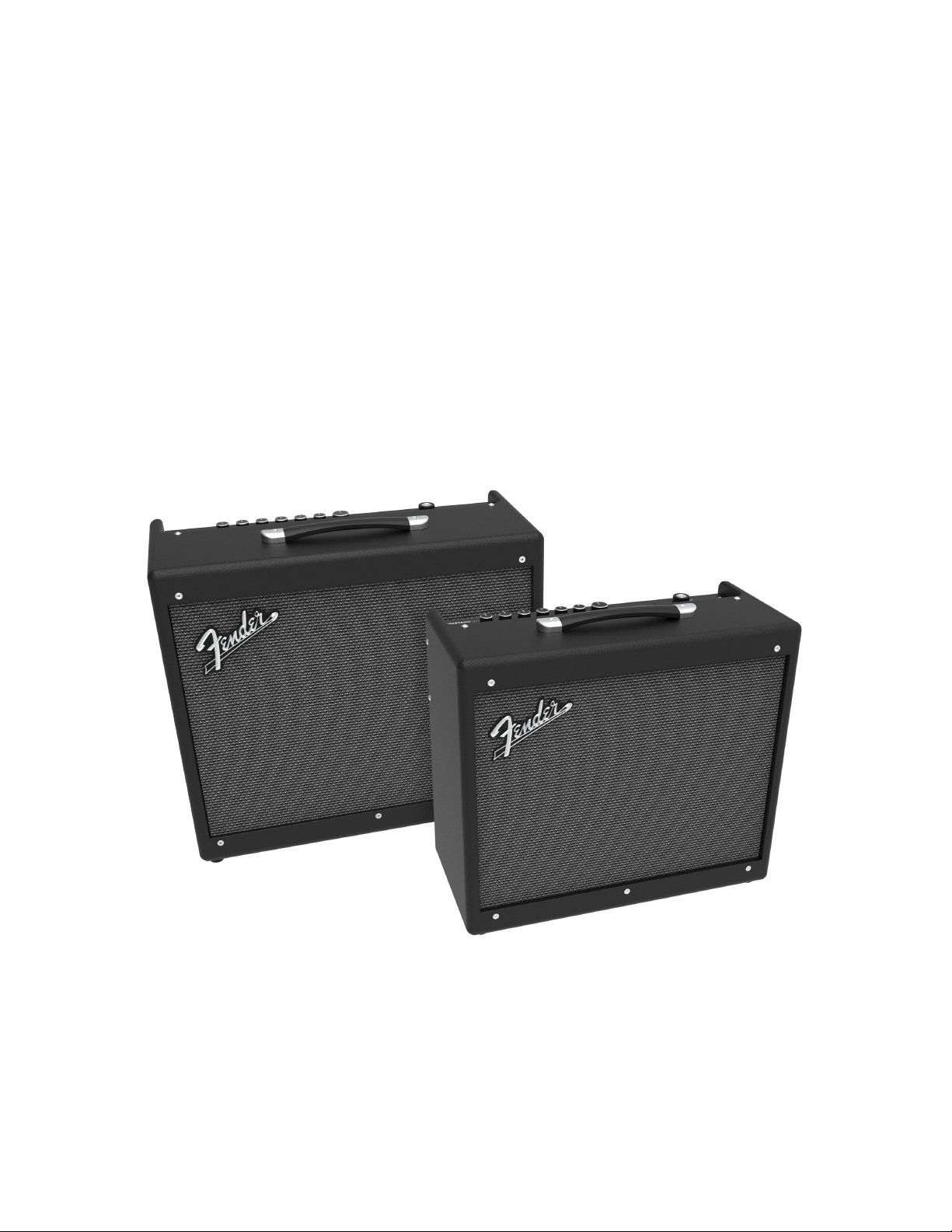
Mustang GTX100 (left) and Mustang GTX50 (right).
1
Page 4
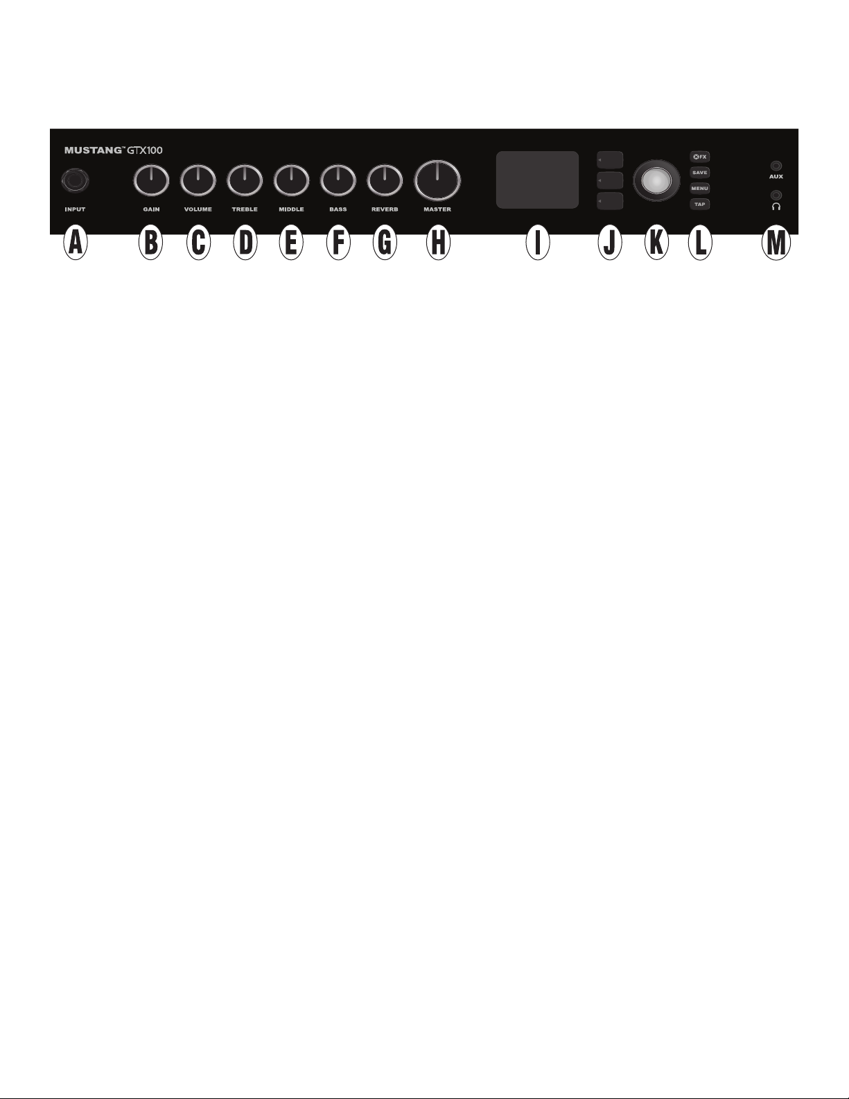
CONTROL PANEL
The Mustang GTX top control panel consists of an instrument input, seven control knobs, display window, three
LAYER pushbuttons, ENCODER wheel, four UTILITY pushbuttons, 1/8” auxiliary input and 1/8” headphone output.
HOLD FOR
TUNER
Mustang GTX100 top panel shown; Mustang GTX50 panel shares same features.
A. INPUT: Plug instrument in here.
B. GAIN: Programmable control knob (see page 3) that aects gain setting in each preset.
C. VOLUME: Programmable control knob that aects amp model volume setting in each preset.
D. TREBLE: Programmable control knob that aects treble tone setting in each preset.
E. MIDDLE: Programmable control knob that aects midrange tone setting in each preset.
F. BASS: Programmable control knob that aects bass tone setting in each preset.
G. REVERB: Programmable control knob that aects reverb setting in each preset.
H. MASTER VOLUME: The only non-programmable knob; controls actual overall volume.
I. DISPLAY WINDOW: Shows preset in use and all its contents and parameters, amplier and eects
menus, and other functions (i.e., tuner, menu functions, etc.).
J. LAYER BUTTONS
PRESET LAYER: Highlights preset layer, where presets are chosen.
SIGNAL PATH LAYER: Highlights signal path in each preset, where amp models, eects types and order of
eects can be modied.
CONTROLS LAYER: Highlights controls layer, where control knob settings can be modied (except Master
Volume).
K. ENCODER: Multipurpose rotary control with press-switch function. For viewing, selecting and adjusting
Mustang GTX presets, controls and other functions.
L. UTILITY BUTTONS
X FX: Bypasses all eects.
SAVE: For saving preset modications and new presets.
MENU: For accessing WiFi, Bluetooth, Tuner, Global EQ, cloud presets and other functions (see page 28).
TAP/TUNER: For setting delay times and modulation rate settings; hold to access built-in tuner.
M. AUXILIARY INPUT, HEADPHONE OUTPUT: 1/8” auxiliary input for connecting external audio devices,
and 1/8” output for headphone use. Headphone output disables internal speaker(s).
2
Page 5
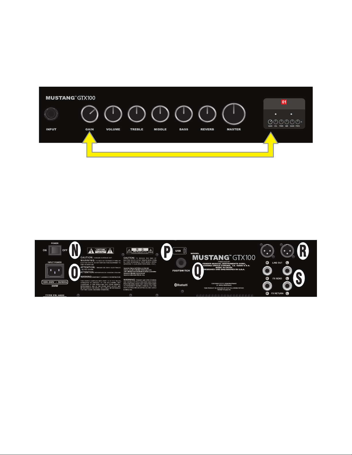
PROGRAMMABLE CONTROL KNOBS
It’s important to note that all top control panel knobs except Master Volume (H) are, as described above,
“programmable.” That means that when a preset is rst selected, the physical position of a top control panel
knob may not indicate the actual setting contained in that preset (the actual setting appears in the display
window). Only the Master Volume control is not programmable—its physical position always indicates actual
overall volume. Once a programmable top control panel knob is turned, however, it and its digital counterpart within a preset become synchronized to the same value, as illustrated here:
ROCK & ROLL
TWIN
REVERB
REVERBFUZZ
Also note that an adjusted control knob setting can be saved in a new preset, or the original preset can be
overridden with the adjusted control knob setting. If the adjusted setting is not saved, the preset will revert
to its pre-programmed control knob settings when returning to the preset after leaving it, or when turning
the amplier o and back on again (see further info under “Editing and Saving Presets” pages 5-6).
REAR PANEL
Mustang GTX100 rear panel shown; Mustang GTX50 rear panel has identical features.
N. POWER: Turns amplier on and o.
O. IEC POWER INLET: Using the included power cord, connect to a grounded outlet in accordance with the
INPUT POWER voltage and frequency specied at the power inlet.
P. USB PORT: Amp connection point for USB audio recording.
Q. FOOTSWITCH: Connect the GTX-7 footswitch. MGT-4 footswitch or EXP-1 Expression Pedal here.
R. LINE OUT: Balanced line outputs for connection to external recording and sound reinforcement equipment.
S. FX SEND/RETURN: Right/left send and return for stereo external eects use. Eects added here are
“global” (not preset-specic) and act as the last elements in the signal path.
3
Page 6
PRESET BASICS
ROCK & ROLL
PRESGAIN BASSMIDTREBVOL
REVERBFUZZ
TWIN
REVERB
AMPLIFIER
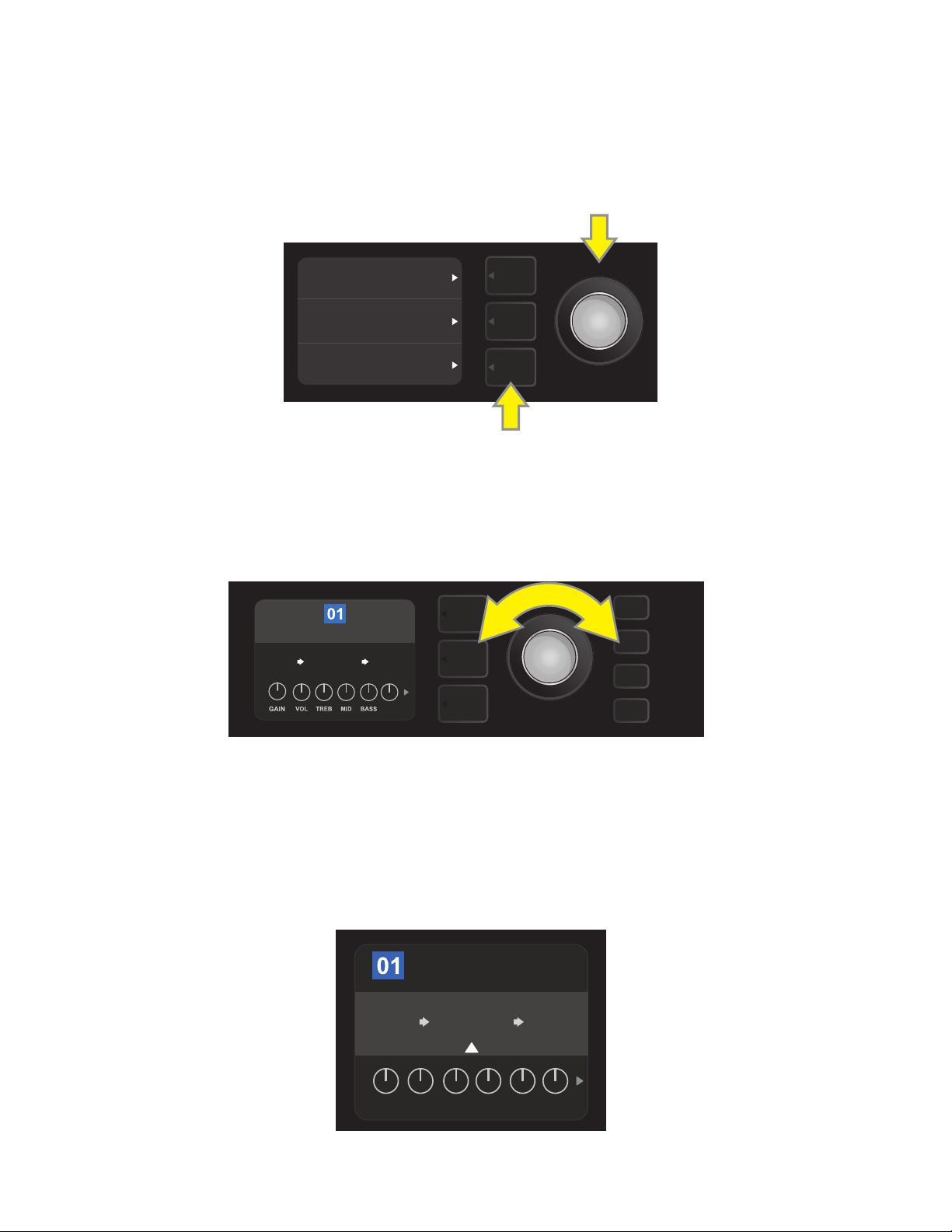
Mustang GTX comes with more than 100 sequentially numbered presets, and users can create and add even
more. Each preset has three “layers” that appear in the DISPLAY WINDOW. These are the PRESET LAYER (top),
SIGNAL PATH LAYER (middle) and CONTROLS LAYER (bottom); the three LAYER BUTTONS provide access to
each layer (see illustration below).
PRESET LAYER
SIGNAL PATH LAYER
CONTROLS LAYER
LAYER BUTTONS
Press to select corresponding layer
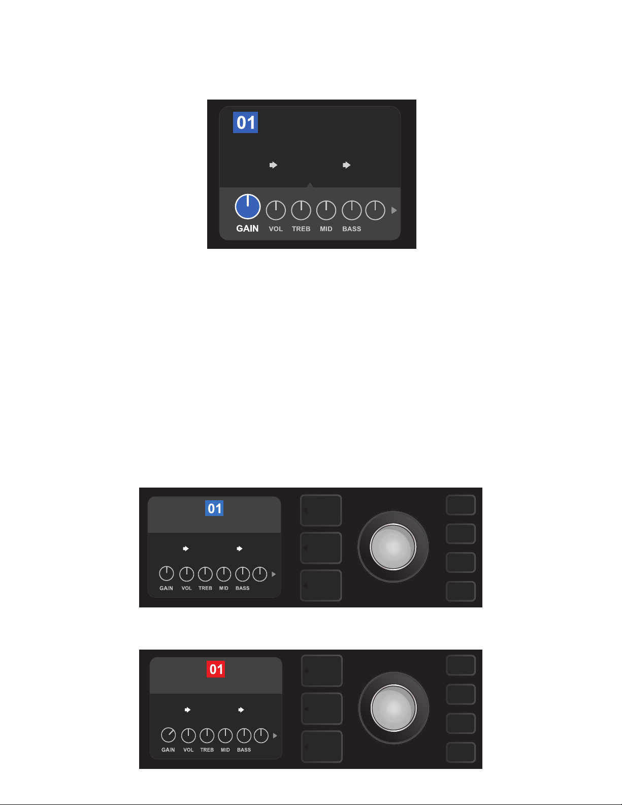
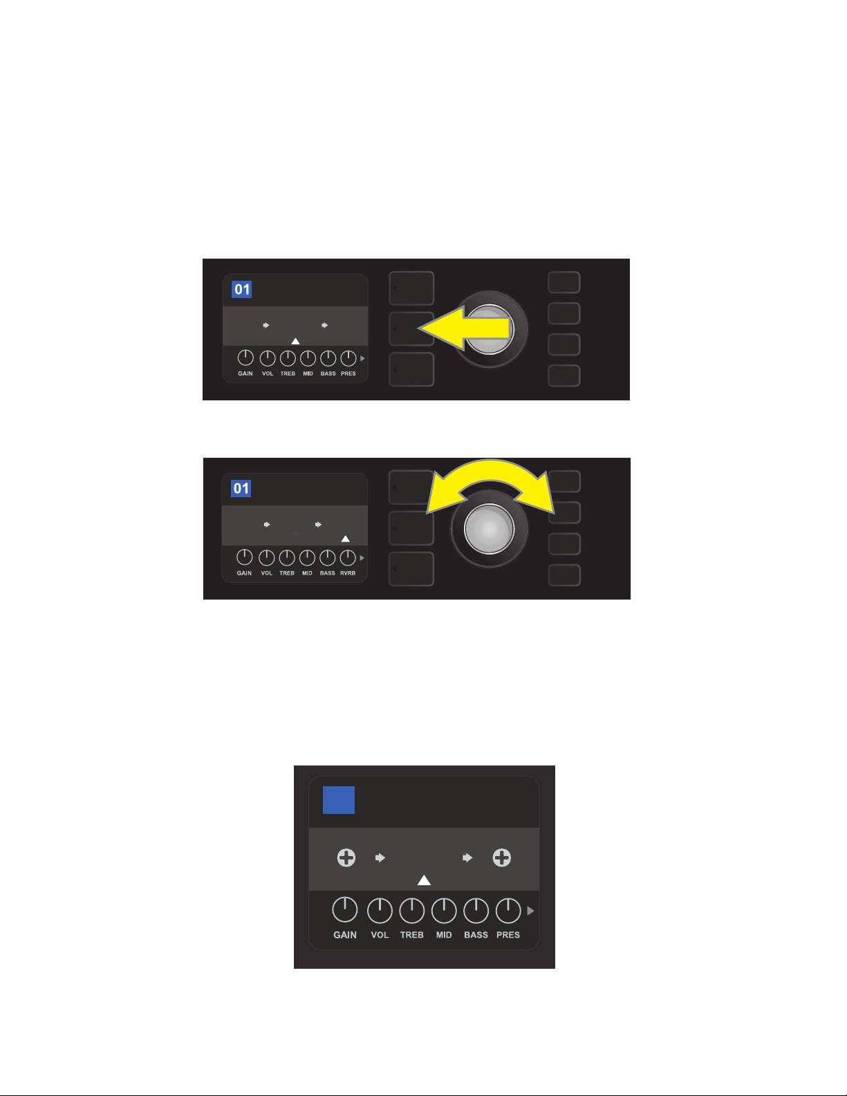
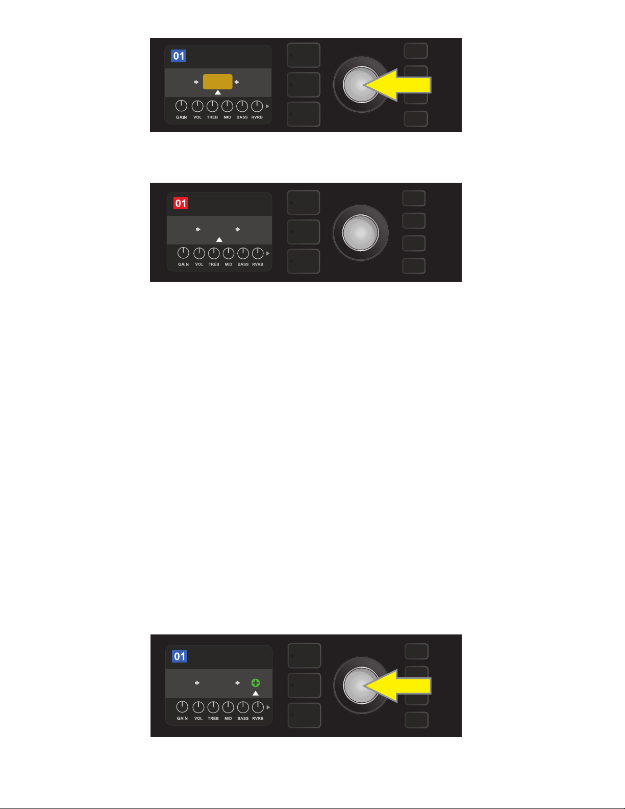
The PRESET LAYER is active when the amplier is rst turned on; the default setting is the rst preset (01).
To scroll through presets, turn the ENCODER (see illustration below); whichever preset is displayed becomes
active. Presets can also be selected by footswitch (see page 40).
ENCODER
ROCK & ROLL
TWIN
REVERB
The rst preset (01) is shown here in the PRESET LAYER.
REVERBFUZZ
PRES
The SIGNAL PATH LAYER of each preset consists of one of Mustang GTX’s many amplier models, and one or
more of dozens of eects and their order (or no eects in some cases). The amp model appears in the center
of the SIGNAL PATH LAYER display. Eects appear to either side of the amp model, representing their position
in the signal path—“pre” to the left of the amp model (placed “before” the amp) or “post” to the right of the
amp model (as in an eects loop). Select any of these items by turning the ENCODER; the selected item in the
SIGNAL PATH LAYER will have a white indicator arrow below it and text describing its position above it (see
illustration below).
Flanked by two eects, the amp model within the preset is selected here in the SIGNAL PATH
LAYER, as indicated by the white arrow and the word “amplier.”
4
Page 7
The CONTROLS LAYER of each preset displays information on whatever amp or eect is highlighted in the
ROCK & ROLL
TWIN
REVERB
AMPLIFIER
PRES
REVERBFUZZ
TWIN
REVERB
ROCK & ROLL
PRES
REVERBFUZZ
SAVE
TWIN
REVERB
ROCK & ROLL
PRES
REVERBFUZZ
SIGNAL PATH LAYER. Amp control knob settings are displayed by default (see illustration below); eects control settings are displayed when an eect is highlighted in the SIGNAL PATH LAYER. Amp and eects controls
are selected by turning the ENCODER.
Close-up detail of the CONTROLS LAYER, in which the gain control for
the amp model within the preset is selected.
Each preset can be used as is. With many dierent amp models, eects types and control settings to choose
among, however, each preset’s SIGNAL PATH LAYER and CONTROLS LAYER settings can easily be modied
and saved for personally individualized sounds (see next section, “Editing and Saving Presets”).
A preset can also be moved to a dierent position or cleared from the list of presets. Further, the entire list of
presets can be restored to its factory state. To perform these functions, see “Preset Organizer” (page 51).
EDITING AND SAVING PRESETS
Within each preset, the amplier control knob settings, amp models, and eects types and parameters can
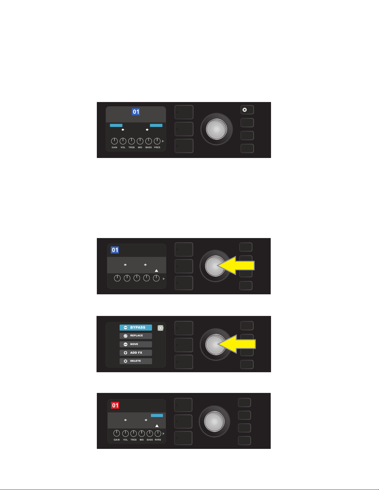
be tailored to individual preference. When a preset is selected, the box containing its number is blue, indicating that no edits have been made to it (see illustration below).
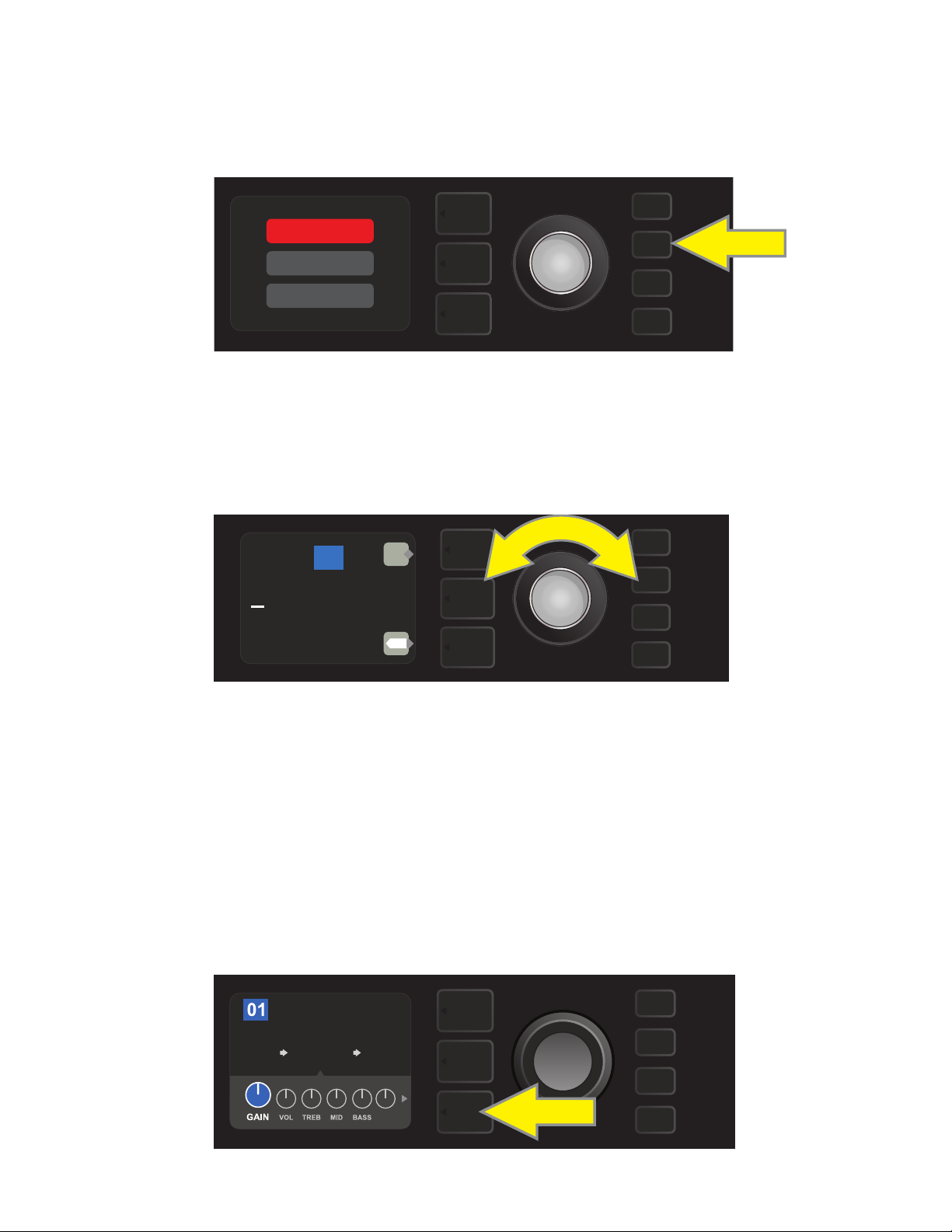
When edits to a preset have been made, the box containing the preset number changes to red, and the SAVE
utility button illuminates (see illustration below).
5
Page 8
If an edited setting is not saved, the preset will revert to its previous settings when returning to the preset after leaving it, or when turning the amplier o and back on again. To save a preset edit, press the illuminated
SAVE utility button to get three options (see illustration below): SAVE (keep preset as edited), RENAME (save
preset with a new name in its current position) and SAVE AS NEW (save preset in a new position with a new
name). Turn the ENCODER to highlight an option; press it to select one.
SAVE
SAVE AS
RENAME
SAVE
To enter a new preset name after choosing RENAME or SAVE AS NEW, use the ENCODER to spell out a new
name of your choice. Press the ENCODER once to activate the cursor; turn it to choose a character (see illus-
tration below). Press ENCODER again to enter that character and move to the next. Repeat until new name is
complete; press the SAVE utility button to keep completed new name, or press the top LAYER button (corresponding with onscreen prompt “back”) to return to the previous screen. Note that when choosing SAVE AS
NEW, the preset will be saved in the next available open position (“101” in the illustration below).
101
NEW PRESET NAME
back
SAVE
X
A favorite preset can be saved quickly and conveniently to a “FAVORITES Setlist” (see page 31). Also, note that
Mustang GTX includes cloud-based backup and restore functions for presets (see page 56).
EDITING PRESET AMPLIFIER CONTROL KNOB SETTINGS
As noted in the “Control Panel” section above, users can change a preset’s amplier control knob settings by
turning the physical control knobs on the top panel (except for Master Volume). This synchronizes the modied settings of the physical control knobs with their corresponding digital counterparts.
These settings can also be changed by editing the digital control knob positions within the CONTROLS
LAYER, which displays the controls specic to the amp in use. To do this, rst access the CONTROLS LAYER by
pressing its LAYER BUTTON (see illustration below).
ROCK & ROLL
AMPLIFIER
TWIN
REVERB
Press the bottom LAYER BUTTON to access the CONTROLS LAYER for the amp model within the preset.
REVERBFUZZ
PRES
6
Page 9
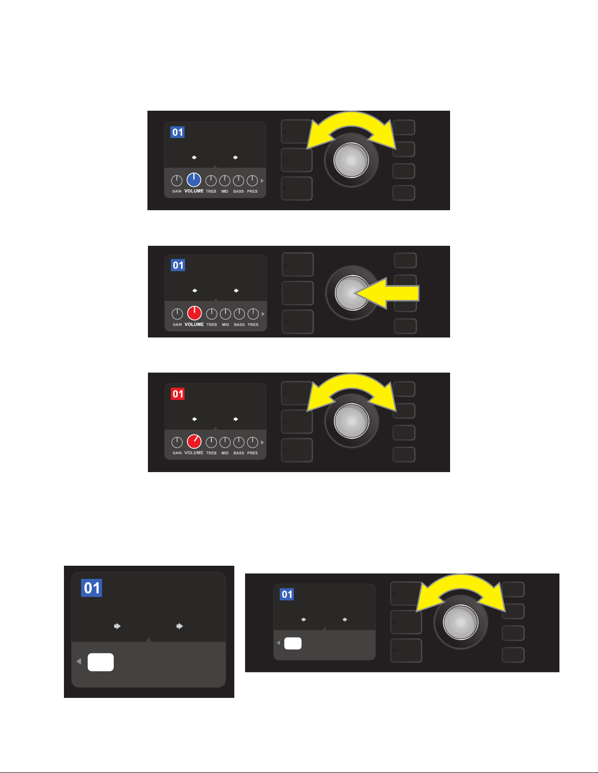
Once in the CONTROLS LAYER, turn and press the ENCODER to scroll through and select a specic digital
amp control knob. Then turn the ENCODER again to change that control’s setting. When a control setting is
changed, the box containing the preset number changes from blue to red (indicating that a preset edit has
been made), and the SAVE utility button illuminates. With the new control setting in place, further edits can
then be made or the SAVE utility button can be pressed to keep completed edits (see illustrations below).
ROCK & ROLL
AMPLIFIER
TWIN
REVERB
Turn the ENCODER to scroll among amp model control knobs.
ROCK & ROLL
AMPLIFIER
TWIN
REVERB
REVERBFUZZ
REVERBFUZZ
Press the ENCODER to select an amp model control knob for adjustment.
ROCK & ROLL
AMPLIFIER
TWIN
REVERB
REVERBFUZZ
Turn the ENCODER again to adjust the selected amp model control knob to preference.
Additional amp and control settings can be found by continuing to scroll through the CONTROLS LAYER of
various amp models within the presets. These consist of “deeper” parameters including sag, bias and gate
controls. Dierent speaker cabinet models are also included. Scroll through, select, adjust and save these
additional parameters in the same manner described directly above (see illustrations below).
ROCK & ROLL
AMPLIFIER
TWIN
REVERB
’65
OFF PRE
TWIN
CAB GATE
POS
Close-up detail showing additional amp and control settings found in the CONTROLS LAYER; in this
case for the Twin Reverb amp model.
MATCH
SAG
REVERBFUZZ
0.0%
BIAS
ROCK & ROLL
AMPLIFIER
’65
OFF PRE
TWIN
CAB GATE
TWIN
REVERB
POS
MATCH
SAG
REVERBFUZZ
0.0%
BIAS
Scroll among, select and adjust additional CONTROLS LAYER amp
and control settings using the ENCODER.
7
Page 10
REPLACING PRESET AMPLIFIER MODELS
ROCK & ROLL
REVERBFUZZ
TWIN
REVERB
AMPLIFIER
’57 DELUXE
STUDIO PREAMP
’57 CHAMP
’57 TWIN
’57 BANDMASTER
’57 DELUXE
’57 CHAMP
STUDIO PREAMP
’57 TWIN
’57 BANDMASTER
ROCK & ROLL
FUZZ
’57
DELUXE
AMPLIFIER
SAVE
REVERB
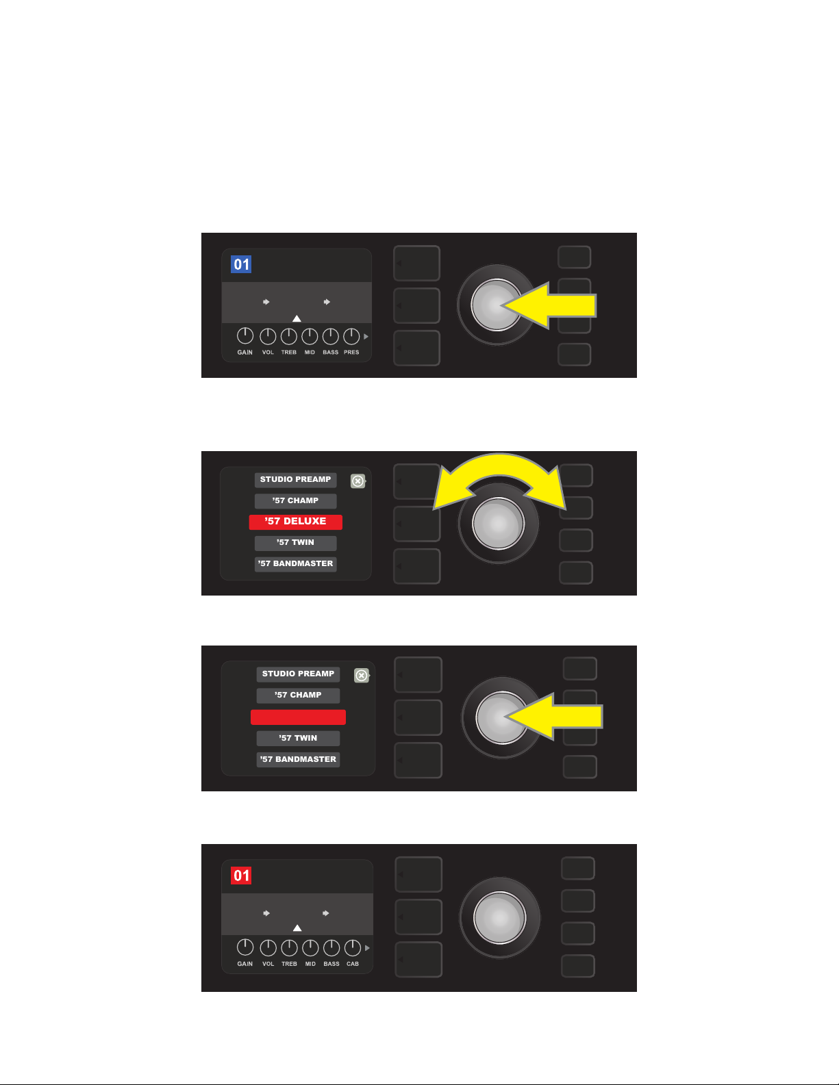
To replace an amplier model within a preset, access the SIGNAL PATH LAYER by pressing its LAYER BUTTON.
The preset amp model will be highlighted. Press the ENCODER to access and scroll through a menu of amp
models; select a new amp model by pressing the ENCODER again. When a new amp model is selected, the
box containing the preset number changes from blue to red (indicating that a preset edit has been made),
and the SAVE utility button illuminates (see illustrations below). With the new amp model in place, further edits
can then be made or the SAVE utility button can be pressed to keep completed edits. Note that pressing the
PRESET LAYER button corresponding to the circled “X” in the DISPLAY WINDOW closes the amp menu.
To replace preset amp model highlighted in the SIGNAL PATH LAYER (as indicated here by the white arrow below it and the
label “amplier” above it) with a dierent amp model, rst press ENCODER to access a menu of other amp models.
Turn ENCODER to scroll through menu of amp models.
Press ENCODER again to select a new amp model for the preset.
With the new amp model in place, continue editing other parameters
or press the illuminated SAVE utility button to keep completed edits.
8
Page 11

LIST OF AMPLIFIER MODELS
This table lists all the preset amp models in Mustang GTX, with a brief description of each. Mustang GTX
amps will be continually revised and updated; this manual indicates current amp models in use.
Studio Preamp Direct-to-mixing-desk studio purity with clean, uncolored tonal response
’57 Champ® Small but mighty late-’50s Fender recording great
’57 Deluxe™ Medium-power late-’50s Fender tweed classic known for thick, compressed overdrive
’57 Twin Original-era 2x12” tweed classic prized for clean-to-dirty versatility
’57 Bandmaster Triple-speaker Fender narrow-panel tweed classic known for crisp highs
’59 Bassman® One of Fender’s greatest tweed amps, which began life as a bass amp before being adopted by countless guitarists
’61 Deluxe
’65 Princeton® Mid-’60s Fender studio favorite with the snappy tone of a single 10” speaker
’65 Deluxe Reverb® Highly popular mid-’60s Fender with great tone whether clean or dirty, cranked in countless clubs
’65 Twin Reverb® An indispensable mid-’60s stage-and-studio favorite prized for producing the Fender clean tone
’65 Super Reverb® Mid-’60s Fender with the distinctive snap of four 10” speakers
Excelsior An elegantly eccentric modern-day Fender model with the distinctive thump of a 15” speaker
’66 GA-15 Inspired by a 1966 Gibson GA-15RVT Explorer, known for its cavernous “full-wet” reverb setting
’60s Thrift Inspired by the garage-classic 1960s Sears Silvertone prized by retro/alternative players
British Watts Inspired by the original 100-watt Hiwatt DR103, which is the classic cleaner-tone British stack
’60s British Inspired by the Vox AC30, which powered the British Invasion and produced remarkable clean and dirty tone
’70s British Inspired by a late-’60s/early-’70s Marshall Super Lead, the amp that powered the dawn of hard rock
From the “Brown Panel” era of the Fender Deluxe, this amp splits the dierence between tweed and “Black Panel”
models
’80s British Inspired by the Marshall JCM800, which produced quintessential ’80s metal tone
British Colour Inspired by the “sludgy” majesty of the Orange OR120
Super-Sonic Modern Fender amp with two cascading preamp gain stages for pronounced sustain
’90s American Based on the Mesa Dual Rectier, which featured distinctive distortion that shaped the “nu-metal” sound
Metal 2000 Modern high-gain scorch based on the EVH® 5150
IIC+Clean Inspired by the clean channel of the Mesa/Boogie Mark IIC+MB
IIC+Lead Quintessential mid-’80s metal tones inspired by the Mesa/Boogie Mark IIC+MB lead channel
Acoustasonic, Bassbreaker, Bassman, Blues Junior, Champ, Deluxe, Deluxe Reverb, Excelsior, Princeton, Showman, Super Reverb, Super-Sonic, Twin Reverb and Vibro-King are trademarks of FMIC. All other non-FMIC product names and trademarks appearing in this manual are the property of their respective owners and are used solely to identify the products
whose tones and sounds were studied during sound model development for this product. The use of these products and trademarks does not imply any aliation, connection, sponsorship, or approval between FMIC and with or by any third party.
III
9
Page 12

LIST OF AMPLIFIER MODELS (CONT’D.)
BB15 Low Based on the low gain structure setting of the Bassbreaker 15
BB15 Med Based on the medium gain structure setting of the Bassbreaker 15
BB15 High Based on the high gain structure setting of the Bassbreaker 15
FBE-100 Inspired by both lead channels (BE and HBE) of the Friedman BE-100
Dual Showman Based on the ’60s/’70s all-tube Fender classic used on big stages everywhere
Tube Preamp Direct-to-mixing-desk studio purity with increased tube console-like harmonic coloration
Acoustasonic
Acoustic Sim
Blues Junior Based on the highly popular warm-toned, moderately powered 1x12” Fender combo with overdrive and FAT switch
Vibro-King Modern Fender classic with touch-sensitive dynamics and distinctive natural overdrive
JC-120 Clean Based on the super-bright clean channel of the classic Roland JC-120 Jazz Chorus
Jubilee Clean Based on the clean channel of the Marshall Silver Jubilee 50-watt head
Jubilee Rhythm Based on the Marshall Silver Jubilee 50-watt head with rhythm clip switch engaged
Jubilee Lead Based on the lead channel of the Marshall Silver Jubilee 50-watt head
Uber Ideal for heavy, aggressive music as inspired by the super-high-gain lead channel of the Bogner Uberschall head
For use with piezo-equipped electric/acoustic guitars. Based on the preamp of Fender’s award-winning Acoustason-
ic amps; exible string-dynamics feature with selectable notch frequency
Six distinctive acoustic guitar simulations for transforming electric guitar with great-sounding acoustic tone. Paired
with Acoustasonic preamp for additional tone shaping
LIST OF CABINET MODELS
This table lists all the preset speaker cabinet models in Mustang GTX, with a brief description of each. Mustang GTX cabinets will be continually revised and updated; this manual indicates current amp models in use.
None Amp circuitry uncolored by speaker simulation
’57 Champ® Based on a late-’50s Fender recording great featuring a low-power 8” speaker with notably snappy tone
’57 Deluxe™ Based on a medium-power late-’50s Fender tweed classic featuring a single 12” alnico-magnet speaker
’65 Twin Based on a prized mid-’60s Fender classic with two 12” ceramic-magnet Jensen® speakers
’57 Bandmaster Based on a late-’50s Fender narrow-panel classic with three 10” Jensen® P10R speakers
’59 Bassman® Based on one of Fender’s greatest original-era tweed amps, with four 10” Jensen® P10R speakers
’61 Brown Based on an early-’60s Fender model featuring a single 12” Oxford speaker with distinct midrange
Acoustasonic, Bassbreaker, Bassman, Blues Junior, Champ, Deluxe, Deluxe Reverb, Excelsior, Princeton, Showman, Super Reverb, Super-Sonic, Twin Reverb and Vibro-King are trademarks of FMIC. All other non-FMIC product names and trademarks appearing in this manual are the property of their respective owners and are used solely to identify the products
whose tones and sounds were studied during sound model development for this product. The use of these products and trademarks does not imply any aliation, connection, sponsorship, or approval between FMIC and with or by any third party.
10
Page 13

LIST OF CABINET MODELS (CONT’D.)
’65 Princeton® Based on a mid-’60s Fender studio favorite with the snappy tone of a single 10” Jensen® C10R speaker
’65 Deluxe Based on a popular mid-’60s Fender mainstay with a single 12” Jensen® ceramic speaker
Excelsior Based on a nonconventional modern Fender amp with a distinctively thumping 15” Special Design speaker
’66 GA-15 Inspired by the single 10” CTS speaker in the 1966 Gibson GA-15RVT Explorer
1x12 EV Based on an open-back Mesa/Boogie Mark IIC+ bubinga cabinet with a single 12” EVM12L speaker
1x12 BB15 Based on Fender’s open-back Bassbreaker 15 cabinet with a single12” Celestion® V-Type speaker
2x12 Blue Inspired by the pair of 12” Celestion® Alnico Blue speakers in the venerable Vox AC30
4x12 75W Inspired by the 75-watt Marshall JCM800 cabinet with four 12” Celestion® G12T75 speakers
4x12B 75W Brighter version of the Marshall JCM800 4x12” cabinet directly above
1x12 Super-Sonic Birch-ply Fender combo cabinet with a single 12” Celestion® Vintage 30 speaker
2x12 Super-Sonic Birch-ply Fender combo cabinet with two 12” Celestion® Vintage 30 speakers
4x12 RCT Based on a closed-back Mesa Boogie Rectier cabinet with four 12” Celestion® Vintage 30 speakers
4x12 GB Based on a Marshall cabinet with four 12” Celestion® Greenback speakers
4x12B GB Brighter version of the 4x12” Marshall cabinet directly above
4x12 V30 Based on a Fender Super-Sonic cabinet with four 12” Celestion® Vintage 30 speakers
4x12B V30 Brighter version of the 4x12” Fender Super-Sonic cabinet directly above
4x12 SOL Based on a closed-back Soldano cabinet with four 12” Eminence® Legend speakers
4x12 FRD Based on a closed-back Friedman 4x12” cabinet with Celestion® Greenback speakers
4x12B FRD Brighter version of the 4x12” Friedman cabinet model directly above
2x15 D130 Based on a Fender Dual Showman cabinet with the distinctive attack of two 15” JBL® D130F speakers
2x12 Jubilee Based on a small Marshall slanted cabinet with two Celestion® G12-75 speakers
Blues Junior Based on the Fender open-back combo cabinet with a single 12” Celestion® A-Type speaker
1x12 LTD Based on the Fender Blues Junior LTD open-back cabinet with a single 12” Jensen® speaker
2x12 JC Based on the classic Roland JC-120 Jazz Chorus 2x12” open-back combo
3x10 VKING Based on the Fender Vibro-King cabinet with three 10” speakers
4x10 SUP Based on the Fender Super Reverb cabinet with four 10” Jensen® speakers
4x12 Uber Based on the Bogner Uberkab cabinet with four12” Celestion® speakers
Acoustasonic, Bassbreaker, Bassman, Blues Junior, Champ, Deluxe, Deluxe Reverb, Excelsior, Princeton, Showman, Super Reverb, Super-Sonic, Twin Reverb and Vibro-King are trademarks of FMIC. All other non-FMIC product names and trademarks appearing in this manual are the property of their respective owners and are used solely to identify the products
whose tones and sounds were studied during sound model development for this product. The use of these products and trademarks does not imply any aliation, connection, sponsorship, or approval between FMIC and with or by any third party.
11
Page 14
EDITING EFFECTS
ROCK & ROLL
TWIN
REVERB
REVERB
FUZZ
POST FX 1
TWIN
REVERB
AMPLIFIER
STUDIO TWIN
02
In addition to amp models, each preset also features various combinations of eects. Eects can be edited in
several ways—they can be bypassed, replaced, moved, added or deleted. Further, the individual settings
of each eect can be modied. Each option is explained below and on the following pages.
Editing the types of eects in use and their position in the signal path happens in the SIGNAL PATH LAYER. To
do this, rst access the SIGNAL PATH LAYER by pressing its corresponding LAYER BUTTON, which will automatically highlight the amplier model in use rst. To highlight an eect, turn the ENCODER in either direction (see illustrations below). The eect will be highlighted with a white arrow below it and a label above it.
ROCK & ROLL
AMPLIFIER
TWIN
REVERB
To access eects, rst press the middle LAYER BUTTON to enter SIGNAL PATH LAYER.
REVERBFUZZ
Turn the ENCODER in either direction to highlight an eect (as indicated
here by the white arrow below it and label above it).
For each preset, note that a placeholder symbol consisting of a plus sign (+) in a circle appears at the right and
left ends of the SIGNAL PATH LAYER (see illustration below). This symbol indicates an open slot into which an effect can be moved or added (see “Adding an Eect,” page 16). In many presets that include one or more eects,
the user must scroll to the far right or far left using the ENCODER in order to see this symbol.
Close-up detail—of a dierent preset that doesn’t include one or more eects—in which open slots that eects can be
placed in are marked by a placeholder symbol consisting of a plus sign in a circle at both ends of the SIGNAL PATH LAYER.
12
Page 15
ROCK & ROLL
TWIN
REVERB
REVERB
FUZZ
POST FX 1
LEVEL DECAY
DWELL DIFF TONE
BYPASSING AN EFFECT
ADD FX
BYPASS
DELETE
MOVE
REPLACE
ROCK & ROLL
TWIN
REVERB
REVERB
FUZZ
BYPASS
SAVE
There are two ways to bypass eects. The rst is a general on-o feature that simply turns o all eects in all
presets with a single press of a button. The second lets users bypass specic individual eects within a preset.
To turn o all Mustang GTX eects in every preset (and turn them back on), press the X FX utility button.
There is no option to save; this is merely a quick way to turn all eects o and back on. When the X FX utility
button is pressed it will illuminate, and a blue “bypass” label will appear above each eect (see illustration
below). If specic individual eects have already been bypassed in a preset, use of the X FX utility button will
not turn them back on.
FX
ROCK & ROLL
TWIN
REVERB
The “X FX” utility button illuminates when pressed, bypassing all eects in all
presets (as indicated by blue “BYPASS” labels above each eect).
To bypass specic individual eects within a preset, highlight it in the SIGNAL PATH LAYER and press the
ENCODER. Select “BYPASS” from the menu of eects placement options and press the ENCODER again. The
SIGNAL PATH LAYER will then indicate that the eect has been bypassed; the box containing the preset number will change from blue to red (indicating that a preset edit has been made), and the SAVE utility button
will illuminate. With the eect now bypassed, further edits can then be made or the SAVE utility button can
be pressed to keep completed edits (see illustrations below).
BYPASSBYPASS
REVERBFUZZ
To bypass a highlighted eect, rst press the ENCODER to access the menu of eects placement options.
Turn ENCODER to highlight “BYPASS” in eects placement options menu, then press the ENCODER to select it.
With the eect bypassed (as indicated here by white arrow below it and blue box containing the label “BYPASS”
above it), continue editing other parameters or press the illuminated SAVE utility button to keep completed edits.
13
Page 16
ROCK & ROLL
TWIN
REVERB
REVERB
FUZZ
POST FX 1
ADD FX
BYPASS
DELETE
MOVE
REPLACE
MODULATION
STOMPBOX
DELAY
REVERB
TOUCH WAH
WAH
RANGER BOOST
OVERDRIVE
GREENBOX
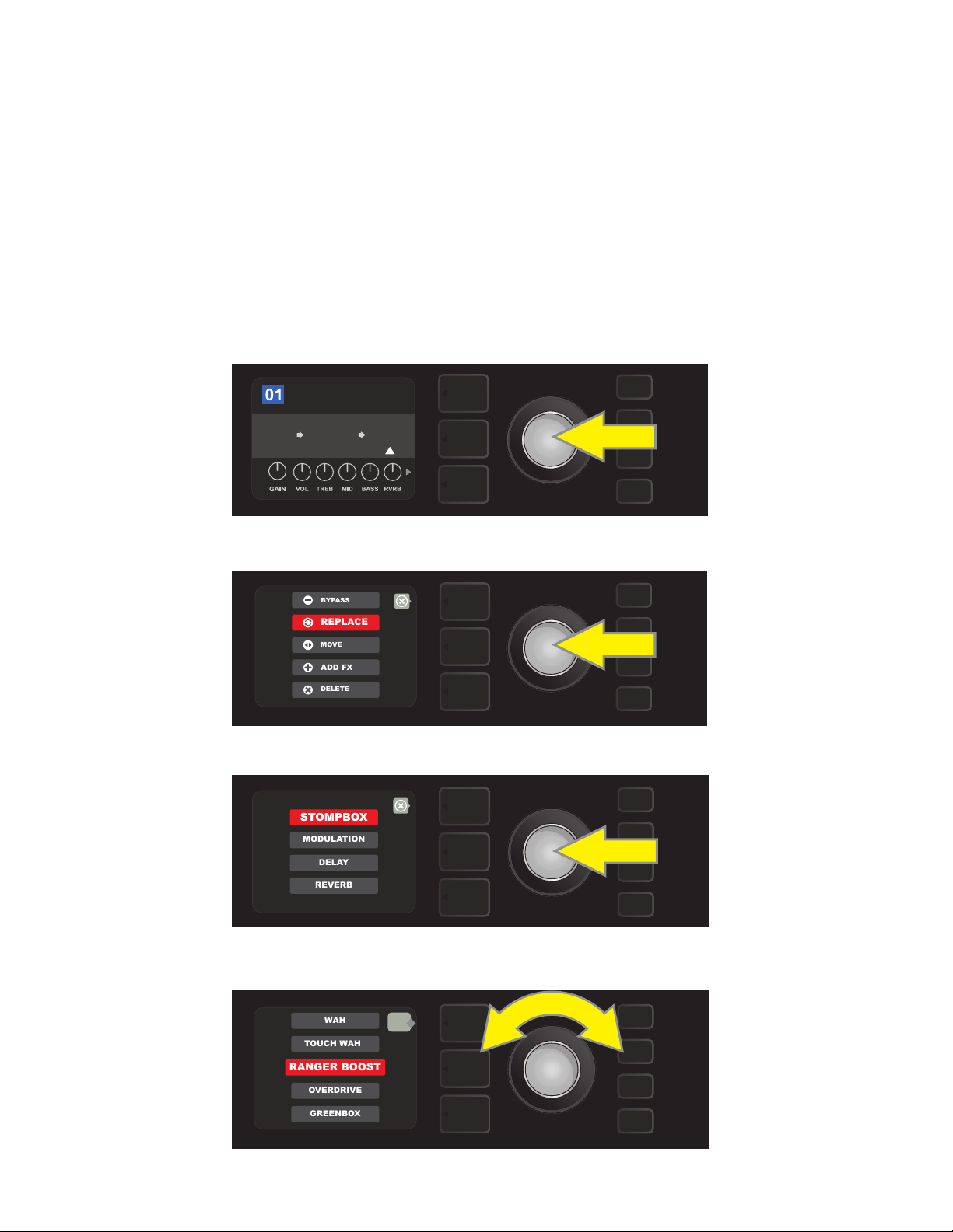
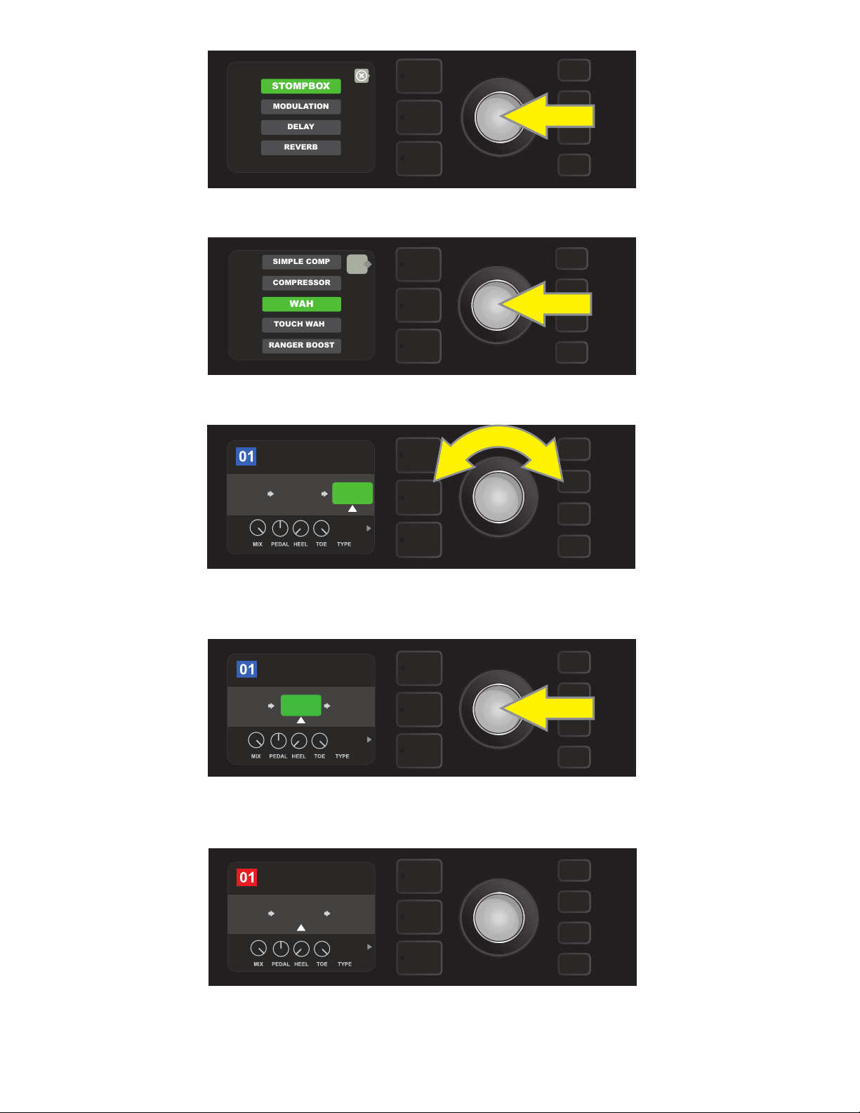
REPLACING AN EFFECT
To replace an eect, highlight the eect to be replaced in the SIGNAL PATH LAYER and press the ENCODER.
Select “REPLACE” from the menu of eects placement options and press the ENCODER again. Select one the four
eects categories that will appear—Stomp Box, Modulation, Delay or Reverb—and press the ENCODER to access
the eects in that category. Scroll through the eects and press the ENCODER to select one as a replacement.
The SIGNAL PATH LAYER will then display the new eect and indicate that the original eect has been replaced;
the box containing the preset number will change from blue to red (indicating that a preset edit has been
made), and the SAVE utility button will illuminate. With the eect now replaced, further edits can then be made
or the SAVE utility button can be pressed to keep completed edits (see illustrations below and on next page).
Note that pressing the PRESET LAYER button corresponding to the circled “X” in the DISPLAY WINDOW closes
the eects placement option and eects category menus; pressing it when it corresponds to the label “back”
(as on the eects menu) returns the user to the previous screen.
To replace a highlighted eect, rst press the ENCODER to access the menu of eects placement options.
Turn the ENCODER to highlight “REPLACE” in eects placement options menu, then press the ENCODER to select it.
Turn the ENCODER to highlight one of four eects categories, then press ENCODER to select eects category.
back
Turn the ENCODER to highlight a replacement eect, then press ENCODER to select it.
14
Page 17
ROCK & ROLL
TWIN
REVERB
REVERB
FUZZ
POST FX 1
ADD FX
BYPASS
DELETE
MOVE
REPLACE
ROCK & ROLL
FUZZ
TWIN
REVERB
POST FX 1
RANGER
BOOST
SAVE
With the eect replaced (as indicated here by white arrow below it and label above it), continue editing other
parameters or press the illuminated SAVE utility button to keep completed edits.
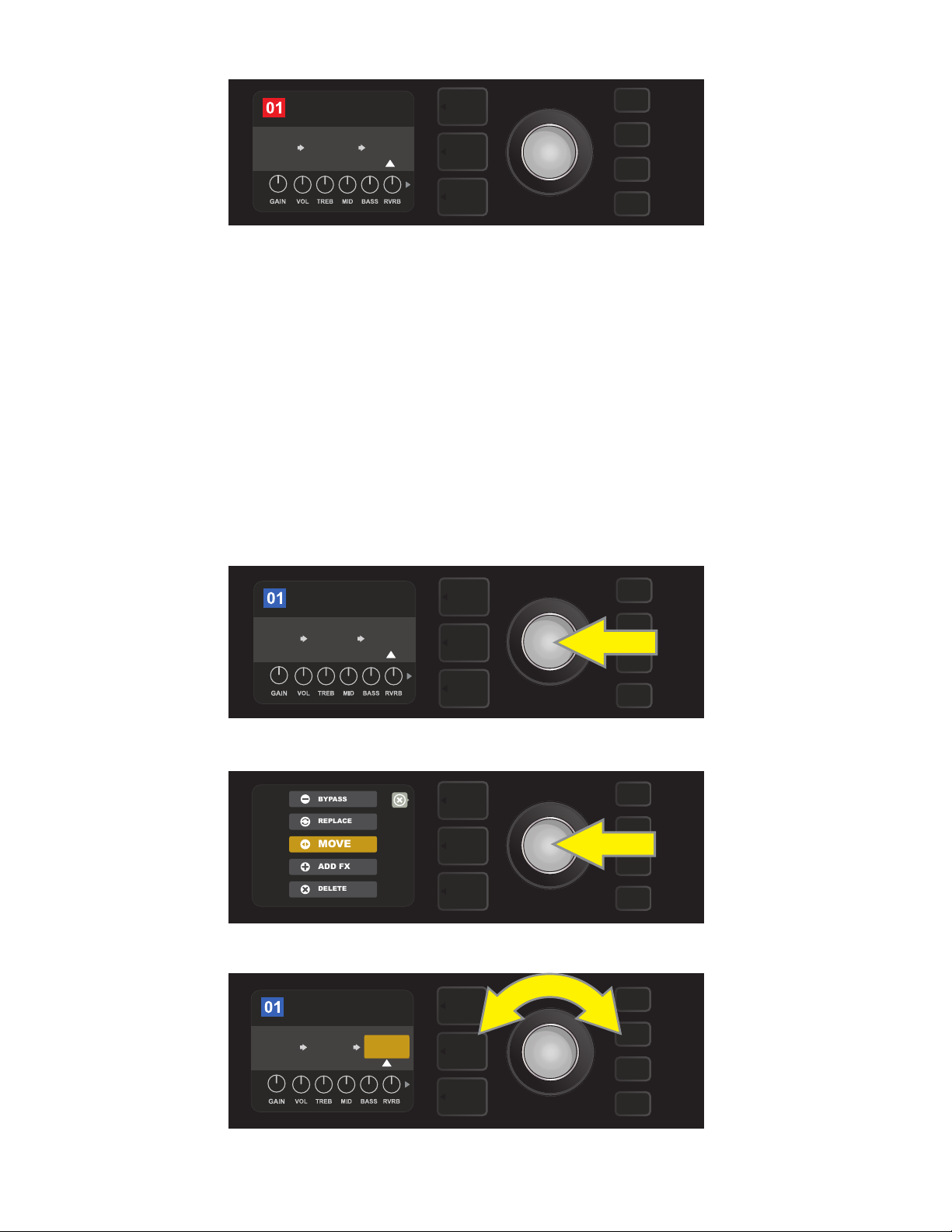
MOVING AN EFFECT
To move an eect to a dierent position in the signal path, highlight the eect to be moved in the SIGNAL
PATH LAYER and press the ENCODER. Select “MOVE” from the menu of eects placement options and press
the ENCODER again. An orange box will appear around the selected eect name, along with a blinking white
arrow indicating that the eect is ready to be moved. Turn the ENCODER to reposition the selected eect;
press the ENCODER to place the eect in a new position.
The SIGNAL PATH LAYER will then display the eect in its new position; the box containing the preset number
will change from blue to red (indicating that a preset edit has been made), and the SAVE utility button will illuminate. With the eect now moved, further edits can then be made or the SAVE utility button can be pressed
to keep completed edits (see illustrations below and on next page).
To move a highlighted eect, rst press the ENCODER to access the menu of eects placement options.
Turn the ENCODER to highlight “MOVE” in eects placement options menu, then press the ENCODER to select it.
ROCK & ROLL
TWIN
REVERB
The selected eect, highlighted with a white arrow below it and label above it, appears in an orange box indi-
cating that it is ready to be moved to a dierent position in the signal path by turning the ENCODER.
POST FX 1
REVERBFUZZ
15
Page 18
ROCK & ROLL
TWIN
REVERB
FUZZ
REVERB
PRE FX 2
After moving the selected eect by turning the ENCODER, press the
ENCODER to select its new position in the signal path.
ROCK & ROLL
FUZZ
PRE FX 2
REVERB
TWIN
REVERB
SAVE
With the eect moved to a new position (as indicated here by white arrow below it and label above it), contin-
ue editing other parameters or press the illuminated SAVE utility button to keep completed edits.
ADDING AN EFFECT
There are two ways to add an eect.
In the rst method, highlight one of the two placeholder plus-sign symbols in the SIGNAL PATH LAYER by
turning the ENCODER. The circle containing the plus-sign symbol will turn green. Press the ENCODER to see
a menu of four eects categories—Stomp Box, Modulation, Delay and Reverb. Highlight a category by turning the ENCODER, then press the ENCODER to access the eects in that category. Scroll through the eects
and press the ENCODER to select an eect.
The SIGNAL PATH LAYER will then display the newly added eect in a green box with a blinking white arrow
below it and a label above it, indicating that the eect can be moved to a dierent position (if preferred) by
turning and then pressing the ENCODER.
When an eect is added, the box containing the preset number will change from blue to red (indicating that
a preset edit has been made), and the SAVE utility button will illuminate. With the eect now added, further
edits can then be made or the SAVE utility button can be pressed to keep completed edits (see illustrations
below and on next page). Note that pressing the PRESET LAYER button corresponding to the circled “X” in the
DISPLAY WINDOW closes the eects category and eect menus; pressing it when it corresponds to the label
“back” returns the user to the previous screen.
ROCK & ROLL
TWIN
REVERB
FUZZ
To add an eect, highlight the placeholder plus-sign symbol by turning the ENCODER to it. The circle contain-
ing the plus-sign symbol will turn green. Press the ENCODER to access a menu of four eects categories.
16
Page 19
TOUCH WAH
WAH
COMPRESSOR
SIMPLE COMP
RANGER BOOST
ROCK & ROLL
TWIN
REVERB
FUZZ
WAH
BABY
POST FX 1
ROCK & ROLL
TWIN
REVERB
FUZZ
WAH
SAVE
POST FX 1
BABY
MODULATION
STOMPBOX
DELAY
REVERB
Select an eects category by scrolling to it and pressing the ENCODER.
back
Select an eect by scrolling to it and pressing the ENCODER.
The newly added eect, highlighted with a white arrow below it and label above it, appears in a green box indi-
cating that it can be left in place or moved to a dierent position in the signal path by turning the ENCODER.
ROCK & ROLL
FUZZ
PRE FX 2
WAH
TWIN
REVERB
BABY
After moving the newly added eect by turning the ENCODER,
press the ENCODER to select its new position in the signal path.
With the added eect in position (as indicated here by white arrow below it and label above it), continue edit-
ing other parameters or press the illuminated SAVE utility button to keep completed edits.
17
Page 20
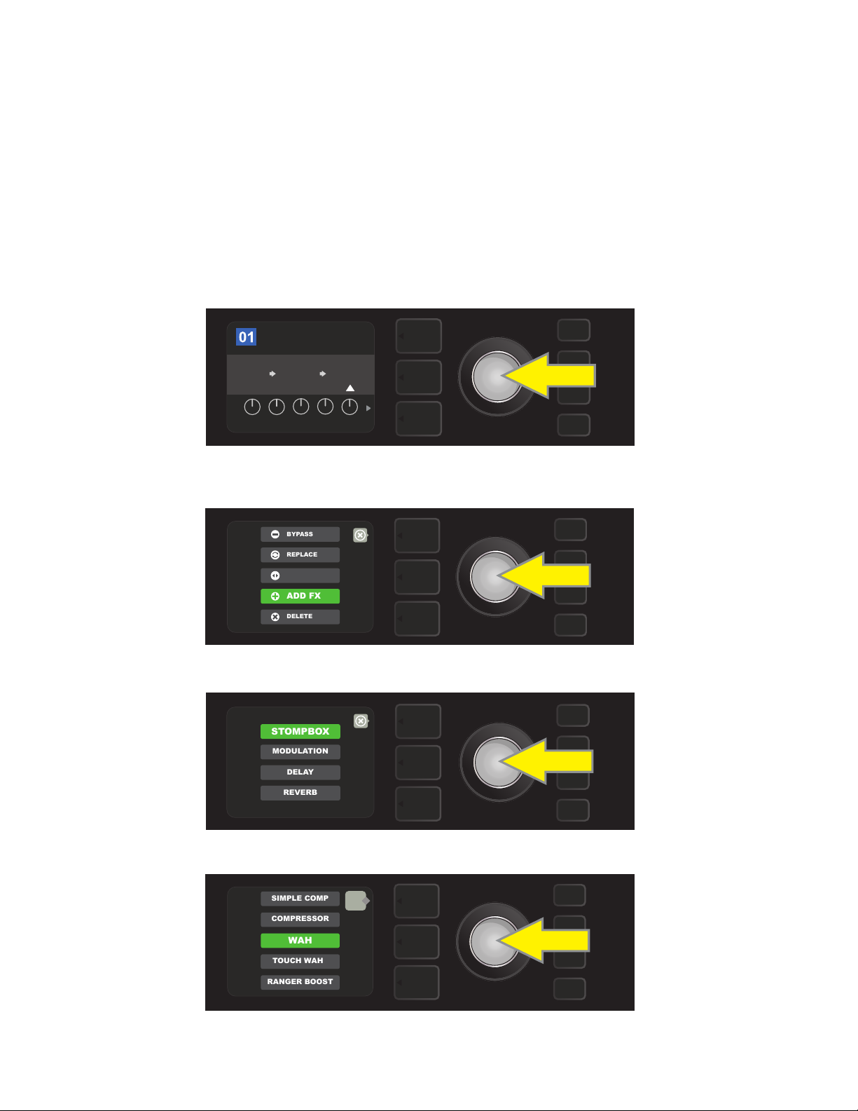
In the second method of adding an eect, highlight an existing eect in the SIGNAL PATH LAYER and press
ADD FX
BYPASS
DELETE
MOVE
REPLACE
MODULATION
STOMPBOX
DELAY
REVERB
TOUCH WAH
WAH
COMPRESSOR
SIMPLE COMP
RANGER BOOST
the ENCODER. Select “ADD FX” from the menu of eects placement options and press the ENCODER again.
Select one the four eects categories that will appear and press the ENCODER to access the eects in that
category. Scroll through the eects and press the ENCODER to select an eect.
The SIGNAL PATH LAYER will then display the newly added eect in a green box with a blinking white arrow
below it and a label above it, indicating that the eect can be moved to a dierent position (if preferred) by
turning and then pressing the ENCODER.
When an eect is added, the box containing the preset number will change from blue to red (indicating that a
preset edit has been made), and the SAVE utility button will illuminate. With the eect now added, further edits can then be made or the SAVE utility button can be pressed to keep completed edits (see illustrations below
and on next page).
ROCK & ROLL
TWIN
REVERB
POST FX 1
REVERBFUZZ
LEVEL DECAY
DWELL DIFF TONE
In another way to add an eect, highlight an existing eect within a preset by turning the
ENCODER to it and pressing the ENCODER to see a menu of four eects categories.
Select “ADD FX” in the eects placement options menu by scrolling to it and pressing the ENCODER.
Select an eects category by scrolling to it and pressing the ENCODER.
back
Select an eect by scrolling to it and pressing the ENCODER.
18
Page 21

ROCK & ROLL
TWIN
REVERB
FUZZ
WAH
SAVE
POST FX 1
BABY
ROCK & ROLL
TWIN
REVERB
REVERB
FUZZ
POST FX 1
LEVEL DECAY
DWELL DIFF TONE
ROCK & ROLL
POST FX 1
WAH
BABY
FUZZ
TWIN
REVERB
The newly added eect, highlighted with a white arrow below it and label above it, appears in an green box
indicating that it can be left in place or moved to a dierent position in the signal path by turning the ENCODER.
ROCK & ROLL
FUZZ
PRE FX 2
WAH
TWIN
REVERB
BABY
After moving the newly added eect by turning the ENCODER, press the
ENCODER to select its new position in the signal path.
With the added eect in position (as indicated here by white arrow below it and label above it), continue edit-
ing other parameters or press the illuminated SAVE utility button to keep completed edits.
DELETING AN EFFECT
To delete an eect from the signal path, highlight the eect in the SIGNAL PATH LAYER and press the ENCODER. Select “DELETE” from the menu of eects placement options and press the ENCODER again; the
eect will be removed from the signal path and another eect in use (if any) will shift into its place. If the
deleted eect was the only eect in the signal path (pre or post), a placeholder symbol consisting of a plus
sign (+) in a circle will appear in its spot.
When an eect is deleted, the box containing the preset number will change from blue to red (indicating
that a preset edit has been made), and the SAVE utility button will illuminate. With the eect now deleted,
further edits can then be made or the SAVE utility button can be pressed to keep completed edits (see illus-
trations below and on next page).
To delete a highlighted eect, rst press the ENCODER to access the menu of eects placement options.
19
Page 22

ADD FX
BYPASS
DELETE
MOVE
REPLACE
Select “DELETE” in the eects placement options menu by scrolling to it and pressing the ENCODER.
ROCK & ROLL
FUZZ
AMPLIFIER
TWIN
REVERB
SAVE
The SIGNAL PATH LAYER will then show the eect has been deleted (as indicated by white arrow), either by replacing
it with a plus-sign placeholder symbol (as seen here) or by shifting another eect (if present) into its position.
EDITING EFFECTS SETTINGS
To edit the control settings of a particular eect, turn the ENCODER to highlight the eect in the SIGNAL
PATH LAYER, then press the CONTROLS LAYER button, which presents the individual controls for each eect.
Turn the ENCODER to scroll through available eect controls, which will each turn blue as they’re highlighted, and press the ENCODER to select a specic eect control, which will then turn red.
After selecting a specic eect control, turn the ENCODER to edit that specic eect control to preference,
and press the ENCODER again to keep the edited eect control setting. The edited eect control will then
turn from red back to blue. When an eect control is edited, the box containing the preset number will
change from blue to red (indicating that a preset edit has been made), and the SAVE utility button will illuminate. With the eect now edited, further eects control edits can then be made or the SAVE utility button can
be pressed to keep completed preset edits (see illustrations below and on next page).
ROCK & ROLL
TWIN
REVERB
LEVEL DECAY
DWELL DIFF TONE
To edit the settings of a particular eect, highlight the eect in the SIGNAL PATH layer
by scrolling to it with the ENCODER; then press the CONTROLS LAYER button.
POST FX 1
REVERBFUZZ
20
Page 23

ROCK & ROLL
TWIN
REVERB
REVERB
POST FX 1
LEVEL
FUZZ
DECAY DWELL DIFF TONE
In the CONTROLS LAYER, highlight an eect control by scrolling to it
ROCK & ROLL
TWIN
REVERB
LEVEL
FUZZ
DECAY
DWELL DIFF
TONE
REVERB
POST FX 1
ROCK & ROLL
FUZZ
SAVE
TWIN
REVERB
LEVEL
DECAY
DWELL DIFF
TONE
REVERB
POST FX 1
ROCK & ROLL
FUZZ
SAVE
LEVEL DECAY
DWELL DIFF TONE
REVERB
POST FX 1
TWIN
REVERB
using the ENCODER; each eect control turns blue as it’s highlighted.
ROCK & ROLL
POST FX 1
REVERB
FUZZ
TWIN
REVERB
LEVEL
DECAY
DWELL DIFF
TONE
Press the ENCODER to select a specic eect control for adjustment, which will then turn red.
Turn the ENCODER to edit the selected eect control to preference.
Press the ENCODER to keep the edited eect control setting; the eect control will return to blue.
With the specic eect control edited to preference, continue editing other parameters
or press the illuminated SAVE utility button to keep completed edits.
21
Page 24

USING THE TAP TEMPO BUTTON
In presets that include Modulation eects, Delay eects or both*, the TAP utility button ashes in time with
the default rate of the last delay eect in the signal path (or last modulation eect if no delay eect is present).
This rate can be left as is, or it can be modied using the TAP utility button. To set a new TAP tempo, tap the
ashing TAP utility button at the desired tempo at least two times (see illustration below). The TAP utility button
will function regardless of which layer is highlighted (PRESET LAYER, SIGNAL PATH LAYER or CONTROLS LAYER).
ROCK & ROLL
TWIN
REVERB
To change the tempo of the rst delay eect (or modulation eect if no delay eect is present), tap
Various time parameters for all delay and modulation eects in the signal path can be adjusted in the CONTROLS LAYER without use of the TAP utility button. In the SIGNAL PATH LAYER, use the ENCODER to highlight the delay or modulation eect to be modied; its controls will then appear in the CONTROLS LAYER.
Enter the CONTROLS LAYER by pressing its corresponding layer button, and scroll to the time parameter to
be changed using the ENCODER. Press and turn the ENCODER to select and adjust the desired time value,
during which the window containing the time value will turn red; press the ENCODER again to keep the new
time value (see illustration below).
REVERBFUZZ
TAP
the TAP utility button at the desired tempo.
ROCK & ROLL
POST FX 2
DELUXE
REVERB
DELAY
LEVEL
1
60ms
DELAY TIME
DELAY
2
TAP
Delay and modulation eects tempos can also be changed by highlighting the time parameter’s numerical value in the
CONTROLS LAYER, then pressing and turning the ENCODER to set the desired tempo.
TAP TEMPO SUBDIVISIONS
Mustang GTX delay and modulation eects can be synched to the player’s preferred BPM rate. To see the
current BPM rate, press the TAP utility button once; the rate will appear in the DISPLAY WINDOW:
back
TAP TEMPO
120 bpm
mode: preset
TAP
* Mustang GTX modulation and delay eects are listed on pages 24-26.
22
Page 25

There are two modes for BPM—”global” and “preset”. “Global” mode applies a single BPM to all presets. In
“preset” mode, each preset has its own BPM, which can be set individually per preset (the default rate is 120
BPM). To switch from one BPM mode to the other, press the bottom LAYER BUTTON corresponding to “mode:
preset” or “mode: global” in the DISPLAY WINDOW; turn the ENCODER to adjust the BPM rate:
back
TAP TEMPO
133 bpm
mode: global
TAP
SETTING NOTE DIVISIONS
To synch an eect to the BPM rate, the user can set a specic “note division” for modulation and delay eects.
When the note division is set, the time value is automatically calculated to t with the current BPM setting. If
the time parameter is changed, the note division is automatically set to “o”.
Note divisions values are o, whole note, half note, dotted half note, half note triplet, quarter note, dotted quarter note, quarter note triplet, eighth note, dotted eighth note, eighth note triplet, sixteenth note, dotted sixteenth note, sixteenth note triplet, thirty second note, dotted thirty second note and thirty second note triplet.
To set note divisions, go to the CONTROLS LAYER of the selected modulation or delay eect by pressing the
corresponding bottom LAYER BUTTON. Use the ENCODER to scroll to and select “NOTE DIVISION” (abbreviated “DIV”); then turn and press the ENCODER to select a note division value:
69
BLACK HOLE VIBE
’59
BASSMAN
5.67
OFF
Hz
LEVEL ROTOR DEPTH
NOTE DIVISION
POST FX 1
VIBRA-
TONE
FDBK PHASE
69
BLACK HOLE VIBE
’59
BASSMAN
5.67
1/8
Hz
LEVEL ROTOR DEPTH
NOTE DIVISION
POST FX 1
VIBRA-
TONE
FDBK PHASE
If all note divisions are o, BPM will correspond to rate of last delay or modulation eect in the signal path.
23
Page 26

LIST OF EFFECTS TYPES
Mustang GTX onboard eects are organized into six category menus: Stompbox eects (15), Modulation eects
(15), Delay eects (13), Reverb eects (14), Dynamics+EQ eects (7) and Filters+Pitch eects (9). Names and
descriptions of each appear below, by category. Mustang GTX eects will be continually revised and updated.
STOMPBOX EFFECTS
Ranger Boost Distortion eect inspired by the ’60s-era Dallas Rangemaster Treble Booster
Overdrive Versatile Fender overdrive specially designed for Mustang GTX
Mythic Drive Inspired by the ’90s-era Klon Centaur germanium-diode overdrive
Greenbox
Overdrive eect inspired by the original late-’70s
Ibanez TS808 Tube Screamer
Blackbox Distortion eect inspired by the Pro Co RAT
Yellowbox Distortion eect inspired by the ’70s-era MXR Distortion Plus
Orangebox Distortion eect inspired by the original late-’70s Boss DS-1
Fuzz
Versatile Fender fuzz with added octave specially
designed for Mustang GTX
Big Fuzz Distortion eect inspired by the Electro-Harmonix Big Mu
Varifuzz Versatile Fender fuzz with bass tightness control
Round Fuzz Inspired by the classic late 1960s Fuzz Face
Octobot Synth-like combination of octave-down eect plus octave-up fuzz
Ram Fuzz Distortion eect inspired by the Electro-Harmonix Big Mu Pi (Ram’s Head model)
Russian Fuzz Same as “Ram Fuzz” above, but based on the Russian-made version of the 1990s
Tube OD Distortion eect inspired by the B.K. Butler Tube Driver
MODULATION EFFECTS
Note that the TAP utility button works with Mustang GTX modulation eects, and ashes when a preset
using one or more modulation eects is in use.
Sine Chorus
Triangle Chorus
Sine Flanger
Triangle Flanger
All non-FMIC product names and trademarks appearing in this manual are the property of their respective owners and are used solely to identify the products whose tones
and sounds were studied during sound model development for this product. The use of these products and trademarks does not imply any aliation, connection, sponsorship, or approval between FMIC and with or by any third party.
Smoothly rounded chorus eect that uses a sine
wave for modulation
Distinctive chorus eect that uses a triangle
wave for modulation
Smoothly rounded anging eect that uses a sine
wave for modulation
Distinctive anging eect that uses a triangle
wave for modulation
24
Page 27

MODULATION EFFECTS (CONT’D.)
Vibratone
Vintage Tremolo
Sine Tremolo
Ring Modulator
Phaser
Classic Fender “stuttering” photoresistor tremolo, as heard in Fender amps such
Smoothly pulsating tube bias tremolo, as heard in amps such as the Fender
Classic late-’60s/early-’70s Fender eect with a
rotating speaker bae
as the Twin Reverb
Princeton Reverb
Creatively non-harmonic dissonance from the early era
of electronic music
Long-indispensable jetliner “whoosh” heard on
countless recordings
Phaser 90 Phase shifter eect inspired by the classic ’70s MXR Phase 90
Vibe Unit Based on the late-’60s Uni-Vibe phaser/vibrato pedal
Harmonic Tremolo Based on the distinctive eect built into certain early-’60s Fender amps
4-Knob Flanger Based on the MXR M117 Flanger
JC Chorus
Based on the bucket-brigade analog chorus of the classic
Roland JC-120 Jazz Chorus amplier
JC Vibrato Inspired by the Roland JC-120 amp’s onboard vibrato eect
DELAY EFFECTS
Note that the TAP utility button works with Mustang GTX delay eects, and ashes when a preset using one
or more delay eects is in use.
Mono Delay Clean, simple and pristine signal repetition
Mono Echo Filter
Stereo Echo Filter
Tape Delay
Stereo Tape Delay Similar to Tape Delay above, but with stereo eld expansion
Multi Tap Delay
Reverse Delay
Ping Pong Delay
Ducking Delay
Mono echo with an evenly spaced wah-like eect
on the signal repetitions
Stereo echo with an evenly spaced wah-like eect
on the signal repetitions
Based on an classic analog tape echo unit with imperfections
that created distinctive “wow” and “utter”
Rhythmic delay that can be subdivided into multiple
“taps” with diering time intervals
Reverses the shape of notes for the classic
“backwards guitar” eect
Repetitions in the stereo eld alternate between right and left,
imparting a “ping pong” eect
Delayed notes “duck” out of the way while playing, and
ll in gaps when not playing
All non-FMIC product names and trademarks appearing in this manual are the property of their respective owners and are used solely to identify the products whose tones
and sounds were studied during sound model development for this product. The use of these products and trademarks does not imply any aliation, connection, sponsorship, or approval between FMIC and with or by any third party.
25
Page 28

DELAY EFFECTS (CONT’D.)
2290 Delay
Memory Delay
Inspired by the TC Electronic TC 2290 delay, a 1980s studio-standard digital delay still
sought after today for its crisp repeats and versatile panning/modulation options
Inspired by the Electro-Harmonix Deluxe Memory Man, a late-’70s “bucket-brigade”
delay pedal that imparts dis- tinctive character to repeats and modulation
Space Delay Based on the beloved Roland RE-201 Space Echo
Tape Plex Faithful recreation of the Maestro Echoplex EP-3 echo
REVERB EFFECTS
Small Hall
Mod. Small Hall
Large Hall
Mod. Large Hall
Small Room
Large Room
Builds on Fender’s Small Hall Reverb by adding lush modulation to internal reverb structure. Added high- and low-frequency cut controls further expand creative possibilities
Strong, bright reverb simulating the size of, for example, a major performance hall and
Similar to Mod Small Hall Reverb above, with modulation added to internal structure of
Warm-sounding kind of reverb heard in larger rooms that aren’t halls, such as many
Simulates the kind of bright reverb often heard in,
for example, a hall the size of a movie theater
other large, cavernous spaces
Fender Large Hall Reverb
Warmer, less echo-y reverb typical of smaller spaces
and classic echo chambers
nightclubs
Small Plate Resonantly metallic reverb with more density and atness than room and hall reverbs
Large Plate
The reverb type heard on countless recordings, based on
the classic (and pool table-sized) EMT 140
’63 Spring Classic early-’60s standalone Fender reverb eect
’65 Spring Fender reverb eect built into classic mid-’60s Fender amps
Arena
Ambient
Shimmer
GA-15 Reverb
Subtle reverb eect typical of notably smaller spaces (even smaller than
Simulates the long-trailing reverberation typical of
large stadiums and arenas
Small Room reverb above)
Sonically radiant combination of reverb and
two-octave pitch shift
Based on the ’60s-era Gibson GA-15 amp reverb, unique in
its ability to go “full wet” (no dry signal)
All non-FMIC product names and trademarks appearing in this manual are the property of their respective owners and are used solely to identify the products whose tones
and sounds were studied during sound model development for this product. The use of these products and trademarks does not imply any aliation, connection, sponsorship, or approval between FMIC and with or by any third party.
26
Page 29

DYNAMICS+EQ EFFECTS
Simple Comp Compressor eect inspired by the classic MXR Dyna Comp
Compressor
Sustain
Metal Gate
Inspired by the MXR M-163 Sustain, a rare 1980s compressor pedal with a particularly
Inspired by the ISP Technologies Decimator II G String pedal. Especially ideal for high-
Same as Simple Compressor above, with added gain,
threshold, attack and release controls
strong compression eect and a short attack time
gain metal, with a very fastattenuation curve
EQ Parametric Parametric midrange equalizer plus bass and treble controls
EQ5 Graphic Similar to the Mesa Boogie Mark IIC+ ve-band graphic equalizer
EQ7 Graphic Seven-band graphic equalizer based on the Boss GE-7
FILTERS+PITCH EFFECTS
Pedal Wah
Touch Wah
Dual-mode wah inspired by the Dunlop Cry Baby
and ’60s-era Vox Clyde McCoy wah pedal
Similar to Pedal Wah above, but controlled by picking
dynamics rather than an expression pedal
Envelope Filter Inspired by the funktastic 1970s Mu-Tron III
Step Filter
Rhythmically choppy modulation eect that dices notes into
distinctly alternating “steps”
Pitch Shifter Simple pitch shifter that adds another note above or below the dry signal pitch
Diatonic Pitch
Pedal Shift
Pedal Harmony
Pedal Detune
Based on pitch-shift functions of the DigiTech Whammy pedal; best when used
Based on harmonizer functions of the DigiTech Whammy pedal; best when used
Based on detuning functions of the DigiTech Whammy pedal; best when used
Pitch shifter that produces a chosen musical interval
to create harmonized notes in key
with EXP-1 Expression Pedal (page 45)
with EXP-1 Expression Pedal (page 45)
with EXP-1 Expression Pedal (page 45)
All non-FMIC product names and trademarks appearing in this manual are the property of their respective owners and are used solely to identify the products whose tones
and sounds were studied during sound model development for this product. The use of these products and trademarks does not imply any aliation, connection, sponsorship, or approval between FMIC and with or by any third party.
27
Page 30

MENU FUNCTIONS
Just to the right of the ENCODER is a vertical column of four utility buttons. The third one down is the MENU
utility button, which enables access to a variety of Mustang GTX special functions (see illustration below).
These functions are referenced elsewhere in this manual; all are listed and briey described here.
SETLIST
CLOUD PRESETS
WiFi & BLUETOOTH
EQ & AMP SETTINGS
FOOTSWITCH
TUNER
After pressing the MENU utility button, use the ENCODER to scroll through and select one of Mustang GTX’s
several dierent MENU functions. These functions are:
SETLISTS: For creation and use of Setlists containing user-selected groups of presets (pages 29-32).
CLOUD PRESETS: Enables cloud preset storage and use (pages 54-55).
WIFI & BLUETOOTH: For turning WiFi on/o, selecting and connecting to a network, and adding a password
(pages 32-34). Also for accessing and using Mustang GTX’s Bluetooth functionality (pages 35-36).
MENU
EQ & AMP SETTINGS: For accessing built-in Global EQ proles (pages 49-50), gain control for USB and line
out (pages 38, 50), Preset Organizer (pages 51-52) and About This Amp feature (page 54). Also enables restoration of factory presets and amplier settings (page 53).
FOOTSWITCH: For use with GTX-7 Footswitch (pages 39-44) and EXP-1 Expression Pedal (pages 45-48). MGT-4
Footswitch is also compatible with Mustang GTX.
TUNER: Enables use of Mustang GTX’s built-in chromatic tuner (page 37).
28
Page 31

SETLISTS
MENU
SETLIST 1
MENU
MENU
For individual convenience, presets can be grouped together in “Setlists.” These are user-created groups containing any arrangement of presets ideal for a particular situation—a gig or rehearsal, a favorites list, genre,
artist list, etc. Simple to create and edit, Setlists personalize and streamline the Mustang GTX experience so
that users can access multiple presets quickly and easily.
To create a Setlist, rst press the MENU utility button and use the ENCODER to scroll to and select SETLIST:
SETLIST
CLOUD PRESETS
WiFi & BLUETOOTH
EQ & AMP SETTINGS
FOOTSWITCH
TUNER
A green plus-sign box will appear; press the ENCODER on it to create a new Setlist:
MENU
A blue box labeled “SETLIST 1” will appear; press the ENCODER on SETLIST 1 to begin adding presets to it:
The green plus-sign box will then reappear; press the ENCODER on it to see a list of presets to select from:
Use the ENCODER to scroll among presets to add to SETLIST 1, then press the ENCODER to select a desired preset:
99 - PRESET
100 - PRESET
1 - PRESET
MENU
2 - PRESET
3 - PRESET
29
Page 32

The selected preset is now added to SETLIST 1; repeat the previous two steps to add additional presets to
33 - PRESET
88 - PRESET
1 - PRESET
25 - PRESET
50 - PRESET
MENU
33 - PRESET
88 - PRESET
1 - PRESET
25 - PRESET
50 - PRESET
MENU
SETLIST 1
MENU
1 - PRESET
MENU
SETLIST 1. Once multiple presets have been added to SETLIST 1, use the ENCODER to scroll through and activate dierent presets within the selected Setlist:
When nished creating and using a Setlist, return to main preset mode by pressing the top LAYER BUTTON.
Note that when doing this, the PRESET LAYER will display whichever preset was last highlighted in the Setlist:
To clear all presets from a Setlist, use the ENCODER to scroll to the Setlist to be cleared, then press the CONTROLS LAYER button corresponding with the “gear” icon:
“CLEAR SETLIST” will appear in a blue box; press the ENCODER on it to clear all the presets in that Setlist. Alternately, press the top LAYER button corresponding to “back” in the DISPLAY WINDOW to not clear a Setlist:
back
CLEAR SETLIST
MENU
To delete a single preset within a Setlist, highlight the preset to be deleted by scrolling to it using the ENCODER; press the CONTROLS LAYER button corresponding with the “gear” icon in the DISPLAY WINDOW:
30
Page 33

“DELETE” will then appear in a blue box; press the ENCODER on it to delete that preset. Alternately, press the PRE-
DELETE
MENU
back
SET LAYER button corresponding to “back” in the DISPLAY WINDOW to not delete the preset from the Setlist:
To create subsequent additional Setlists, repeat the steps on pages 29 and 30. These will automatically be
labeled “SETLIST 2,” “SETLIST 3” and so on in numerical order.
Note that Mustang GTX includes cloud-based backup and restore functions for setlists (see page 56).
SETLISTS: QUICK-SAVE PRESET “FAVORITES”
A favorite preset can be saved quickly and conveniently to a “FAVORITES” Setlist. To save a preset in “FAVORITES,”
simply press and hold the ENCODER for a few seconds until the preset number block turns from blue to gold:
85
BLUES 1951
EXCEL-
SIOR
SIMPLE
COMP
OFF
BRT
The preset is automatically added to a Setlist titled “FAVORITES,” which can be accessed by pressing the
MENU utility button and using the ENCODER to scroll to and select “SETLIST.” The “FAVORITES” Setlist is always
the rst one displayed:
SETLIST
CLOUD PRESETS
WiFi & BLUETOOTH
EQ & AMP SETTINGS
FOOTSWITCH
TUNER
FAVORITES
+
MENU
MENU
Press the ENCODER on “FAVORITES” to scroll among and select the presets stored there:
1
29 DUAL CHORUS
2
95 GILA MONSTER
3
34 MEANER STREETS
85 BLUES 1951
4
+
back
MENU
To remove a preset from the “FAVORITES” Setlist, press and hold the ENCODER wheel again for a few seconds
until the preset number block turns from gold to back to blue.
31
Page 34

SETLISTS MENU SHORTCUT
The Setlist menu can be quickly and easily accessed using a shortcut straight from Mustang GTX’s top control panel. Simply press and hold the top LAYER BUTTON, and the Setlist view will be displayed:
FAVORITES
+
MENU
NOTE: The maximum number of Setlists is 25 (including “FAVORITES”); each Setlist can contain a maximum of
50 presets.
WIFI USE
Mustang GTX’s WiFi connectivity delivers easy wireless network access, enabling users to get the latest Mustang GTX rmware updates (see page 60). To get started, press the MENU utility button and use the ENCODER
to scroll to “WIFI & BLUETOOTH,” then press the ENCODER on “WiFi”.
The default WiFi setting is “o,” indicated by a red box labeled “WIFI OFF.” Press the ENCODER again to turn WiFi
on, indicated by a green box labeled “WIFI ON.” When WiFi is on, use the ENCODER to scroll through available
networks; select a network by pressing the ENCODER on it. If a known network is not displayed, it can be
entered manually by selecting the “ADD HIDDEN NETWORK” option at the end of the list of available networks
and using the ENCODER to enter the characters (as shown on page 6). Once a network is chosen, select “CONNECT” from the menu shown by pressing the ENCODER on it (other options in this menu are covered on page 34).
After choosing “CONNECT,” the amp will then prompt the entry of a password. To spell out a password, press the
ENCODER once to activate the cursor and turn it to choose a character. Press ENCODER again to enter that character and move to the next; repeat until password is complete. When password is complete, press the top LAYER
button (corresponding with onscreen prompt “done”). Successful network connection is indicated by a green
dot to the left of the network name. All steps are illustrated below and on the following page.
Note that pressing the PRESET LAYER and CONTROLS LAYER buttons also enable closing out of some menus
(indicated by an “x”) or returning to the previous step (indicated by the label “back”).
SETLIST
CLOUD PRESETS
WiFi & BLUETOOTH
EQ & AMP SETTINGS
FOOTSWITCH
TUNER
MENU
To enable WiFi, rst press the MENU utility button.
32
Page 35

MENU
WIFI OFF
back
MENU
WIFI ON
NETWORK 1
NETWORK 3
NETWORK 2
back
MENU
ADD HIDDEN NETWORK
NETWORK 3
NETWORK 2
NETWORK 1
back
MENU
CONNECT
FORGET
INFO
MODIFY
back
SETLIST
CLOUD PRESETS
WiFi & BLUETOOTH
EQ & AMP SETTINGS
FOOTSWITCH
TUNER
MENU
Use the ENCODER to scroll through the menu to “WiFi & Bluetooth,” then press the ENCODER and select “WiFi”.
The default WiFi setting is “o” (labeled in a red box); press the ENCODER to turn WiFi on (labeled in a green box).
When WiFi is on (as labeled in green box), use the ENCODER to scroll through available
networks; select a network by pressing the ENCODER on it.
A network can be accessed manually by scrolling to and selecting “ADD HIDDEN NETWORK,” and
entering characters by turning and pressing the ENCODER.
After choosing a network, select “CONNECT” from the menu shown by pressing the
ENCODER on it (other options on this menu are covered on page 34).
33
Page 36

MENU
ENTER PASSWORD:
*******
back
After selecting “CONNECT,” enter a password by turning and pressing the ENCODER to add each character.
MENU
done
ENTER PASSWORD:
A B C D E F G
MENU
When password is complete, press the PRESET LAYER button (corresponding with onscreen prompt “done”).
back
WIFI ON
NETWORK 1
NETWORK 2
NETWORK 3
MENU
A green dot to the left of the network name indicates successful network connection.
When WiFi is turned on in Mustang GTX, there are other network menu options in addition to “CONNECT.”
These are labeled “FORGET,” “MODIFY” and “INFO” (see illustration below). Use the ENCODER to scroll through
and select one of these options, which are described below.
back
CONNECT
FORGET
MODIFY
INFO
Close-up detail of DISPLAY WINDOW showing additional WiFi network options “FORGET,” “MODIFY” and “INFO”.
FORGET: For disconnecting a network and removing it from the amp’s memory. To re-establish a connection
with a “forgotten” network, follow the steps for “ADD HIDDEN NETWORK” (pages 32-33).
MODIFY: For modications to the current network’s displayed “SSID,” “PROTOCOL” and “PASSWORD” paramters. Use the ENCODER to scroll to and select one of these parameters, then turn and press the ENCODER to
enter individual characters until modications are complete.
INFO: Displays the current network’s name (SSID), signal description, protocol, and connection status. This
information can not be modied by the user.
34
Page 37

BLUETOOTH USE
MENU
BLUETOOTH ON
back
Mustang GTX ampliers feature Bluetooth connectivity for easy pairing with streaming audio devices and
the Fender Tone™ application. Favorite music streaming applications from the user’s audio device can be
used to stream audio to Mustang GTX.
To enable Bluetooth, press the MENU utility button and use the ENCODER to scroll to “WIFI & BLUETOOTH,”
then press the ENCODER on “BLUETOOTH”. The default Bluetooth setting is “o,” indicated by a red box
labeled “BLUETOOTH OFF.” Press the ENCODER again to turn Bluetooth on, indicated by a green box labeled
“BLUETOOTH ON.” Once Bluetooth is on, select “MUSTANG GTX” on the external device being connected to
the amp. Users who wish to rename Mustang GTX on their external devices can do so by pressing the CONTROLS LAYER button corresponding to the “gear” icon in the DISPLAY WINDOW, and using the ENCODER to
enter each character in a new name (as shown on page 6). Pressing the PRESET LAYER button enables closing
out of a menu (indicated by an “x” in a circle) or returning to the previous step (indicated by the label “back”).
Note that Bluetooth audio streaming and USB audio (page 38) can not be used simultaneously.
SETLIST
CLOUD PRESETS
WiFi & BLUETOOTH
EQ & AMP SETTINGS
FOOTSWITCH
TUNER
MENU
To enable Bluetooth, rst press the MENU utility button.
SETLIST
CLOUD PRESETS
WiFi & BLUETOOTH
EQ & AMP SETTINGS
FOOTSWITCH
TUNER
MENU
Use the ENCODER to scroll through the menu to “WIFI & BLUETOOTH,” then press the ENCODER on “BLUETOOTH”.
back
BLUETOOTH OFF
MENU
The default Bluetooth setting is “o” (labeled in a red box); press the ENCODER to turn Bluetooth on (labeled in a green box).
When amp Bluetooth function is on (as labeled in green box), select “MUSTANG GTX” on external device.
35
Page 38

When a streaming device is connected to Mustang GTX, a Blutooth icon will appear at the top left of the
DISPLAY WINDOW, indicating streaming readiness:
09
BASIC BROWN DELUXE
’61
DELUXE
TONE
When the Fender TONE app is connected to Mustang GTX, a “TONE” icon will appear at the top left of the
DISPLAY WINDOW:
09
BASIC BROWN DELUXE
’61
DELUXE
TONE
BLUETOOTH VOLUME CONTROL
The volume level of a Bluetooth device used with Mustang GTX can be controlled using the volume control
on the external device itself, or by using the “BT & AUX VOLUME” menu function. To use this function within
the BLUETOOTH menu, use the ENCODER to scroll to and select “BT & AUX VOLUME”. Use the ENCODER to
scroll to and select one of four options. “MASTER” enables Bluetooth volume to be set using the Mustang
GTX top panel MASTER VOLUME control. “HIGH” and “LOW” oer further customized volume levels, and
“NORMAL” returns the user to the amp’s “medium” default Bluetooth volume setting (see illustrations below).
back
BLUETOOTH ON
RENAME AMP
BT & AUX VOLUME
HIGH
NORMAL
LOW
MASTER
back
MENU
MENU
36
Page 39

BUILT-IN TUNER
TUNER
TUNER
A
0
To access Mustang GTX’s built-in chromatic tuner, press and hold TAP utility button for two seconds, or press
the MENU utility button and select TUNER by turning and pressing the ENCODER (see illustrations below).
The letter name of the note is displayed, and vertical bars on either side of the longer vertical center bar will
illuminate red to indicate varying degrees of sharpess (to the right) and atness (to the left). Precise numerical
pitch values (in cents) also appear on both sides of the display. When the note is in tune, the center vertical bar
will illuminate in green. When nished tuning, exit tuner mode by pressing the PRESET LAYER button. Note
that tuner use mutes speaker output. and that the GTX-7 Footswitch also has a tuning function (see page 44).
SETLIST
CLOUD PRESETS
WiFi & BLUETOOTH
EQ & AMP SETTINGS
FOOTSWITCH
TUNER
MENU
TUNER
-50 +50
view
MENU
Note also that when in TUNER mode, the original Mustang GT “bouncing ball” tuner mode remains available
by pressing the bottom LAYER BUTTON corresponding to “view” in the DISPLAY WINDOW (see illustrations
below). Mustang GTX automatically saves the user’s preferred tuner mode.
view
37
Page 40

AUXILIARY AND HEADPHONE JACKS
The Mustang GTX control panel features two 1/8”-inch jacks—an auxiliary input for connecting external
mobile/audio devices and an output for convenient headphone use.
Note that when using the auxiliary input, volume levels for external devices are set using volume controls on
the external devices themselves, or by using the Mustang GTX “BT & AUX VOLUME” menu function described
on page 36. Also note that when headphones are plugged in, speaker output is muted.
USB CONNECTIVITY
The Mustang GTX rear panel features a USB audio port for recording. Using a micro USB cable (not included),
connect a computer with recording software to this port. No external driver is needed
to connect to an Apple computer. To connect to a Windows-based computer, the user
must download the ASIO driver setup with Fender Mustang device, available at www.
fender.com/support/articles/fender-universal-asio-drive. Note that USB audio and
Bluetooth audio streaming (page 35) can not be used simultaneously.
A gain control for the USB is located in the “EQ & AMP SETTINGS“ menu. Press the
MENU utility button, then use the ENCODER to scroll to and select “EQ & AMP SETTINGS“, and then “LINE OUT/
USB GAIN”. Use the ENCODER to scroll to and select a new USB gain value (page 50).
LINE OUT AND FX SEND/RETURN
Mustang GTX ampliers feature rear-panel balanced line output jacks (right and left) for connection to external recording and sound reinforcement equipment (see illustration below).
Close-up detail of rear-panel right and left balanced line outputs.
The gain control described above for the USB audio port can also be used for the line out, using the same steps.
Mustang GTX also features an eects loop. The right/left FX send and right/left FX return jacks on the far
right of the rear panel are for mono or stereo external eects use (see illustration below); a mono eect can be
plugged into the right or left channel. Note that eects connected to these jacks are “global” (not preset-specic) and will act as the last elements in the signal path.
Close-up detail of rear-panel right and left FX send/return jacks.
38
Page 41

FOOTSWITCH USE
Three foot-control devices can be used with Mustang GTX ampliers—the GTX-7 and MGT-4 footswitches
and the EXP-1 Expression Pedal.
The seven-button GTX-7 Footswitch comes with Mustang GTX100 and is optional for Mustang GTX50. It enables convenient remote foot control of several functions, including the built-in tuner, amp preset selection,
eects bypass, 60-second looper and more. The EXP-1 Expression Pedal, optional for both Mustang GTX amps,
is a dual-mode digital pedal that controls Mustang GTX volume and amp/eect parameters.
The four-button MGT-4 Footswitch is optional for both Mustang GTX amp models. Note that instructions for
using the MGT-4 Footswitch can be found online in the Mustang GT Guitar Amplier Expanded Owner’s Manual
Rev. A (PN 7712493000), and in the Mustang GT Guitar Amplier Addendum to Expanded Owner’s Manual Firmware V2.0 (PN 7715279000).
Connect the GTX-7 or MGT-4 footswitch to the FOOTSWITCH jack on the amp’s rear panel. The amplier automatically defaults to the connected footswitch while the amp is fully booted. The GTX-7 or MGT-4 footswitch
can be combined with the EXP-1 Expression Pedal by “chaining” the two pedals together.
The GTX-7 Footswitch has seven buttons—a BANK UP button at upper left, a MODE/TUNER button at upper
right, and ve numbered FUNCTION buttons along the bottom. Three MODE LEDs are at upper right, and ve
FUNCTION LEDs are arrayed with one above each FUNCTION button. The DISPLAY WINDOW is at top center.
A. BANK UP BUTTON: Used to move up and down through consecutive groups (“banks”) of ve presets.
GTX-7 FOOTSWITCH FEATURES
B. DISPLAY WINDOW: Displays footswitch function currently in use.
C. MODE LEDS: Color-coded LEDs indicate which of three modes is in use—PRESETS (red), EFFECTS (amber)
or LOOPER (green).
D. MODE/TUNER BUTTON: Used to select among PRESETS, EFFECTS and LOOPER modes; press and hold for
chromatic TUNER mode.
E. FUNCTION BUTTONS/LEDS: Five numbered buttons enable foot control of various Mustang GTX func-
tions, depending on footswitch mode in use. Red LEDs above each FUNCTION BUTTON indicate various
functions in use.
39
Page 42

GTX-7 FOOTSWITCH: MODES
The GTX-7 Footswitch oers three Mustang GTX modes—PRESETS, EFFECTS and LOOPER. To choose one, cycle through them by stepping on the MODE button (D) at the upper right of the footswitch repeatedly until
the desired mode is reached, as indicated by its color-coded MODE LED (C).
PRESETS MODE
PRESETS mode enables the user to reach any of Mustang GTX’s many presets using the GTX-7 Footswitch. To
do this, step on the MODE button (green arrow in illustration below) until PRESETS mode is activated, as indicated by the illuminated red MODE LED directly to the right of the label “PRESETS.”
When the GTX-7 Footswitch is in PRESETS mode, presets become available in consecutive groups of ve called
“banks,” with each of the ve presets in a bank sequentially assigned to FUNCTION buttons 1, 2, 3, 4 and 5. To
move “upward” through subsequent banks of ve presets, step on the BANK UP button (blue arrow in illustra-
tion below). To move “downward” to the preceding bank of ve presets, step on and hold the BANK UP button.
When the bank containing the desired preset is reached, select the desired preset within that bank by stepping on its corresponding FUNCTION button (yellow arrows in illustration below). When the desired preset has
been selected, its corresponding red FUNCTION LED will illuminate, and the DISPLAY WINDOW will show the
preset in use (see illustration below, in which preset 3 is active). The PRESETS mode LED will ash at the tempo of
time-based eects; to change tempo using the GTX-7, tap twice on the currently selected PRESET footswitch.
Note that when activating PRESETS mode, the GTX-7 Footswitch will automatically set itself to whatever MUSTANG
GTX preset is already set on the amp. This preset will be assigned to the footswitch FUNCTION button corre-
sponding to the preset’s position within its bank (1, 2, 3, 4 or 5). For example, if the amp is set to preset number 33, the GTX-7 Footswitch in PRESETS mode will also be set to preset number 33 and will assign that preset
to FUNCTION button 3 (the third preset in the bank containing presets 31, 32, 33, 34 and 35).
EFFECTS MODE
EFFECTS mode lets the user turn the rst ve eects in a Mustang GTX preset on and o using the GTX-7
Footswitch (known as the EFFECTS mode default or “rst ve” setting).
To do this, step on the footswitch MODE button (green arrow in illustration on next page) until EFFECTS mode is
activated; the MODE LED directly to the right of the label “EFFECTS” will illuminate in amber and “EFF” will appear in the DISPLAY WINDOW (see illustration on next page). Any eects in the active preset are then assigned to
the footswitch FUNCTION buttons—labeled “FX1”, “FX2”, “FX3”, “FX4” and “FX5” for this purpose (yellow arrows in
illustration below). When an eect is on, the red FUNCTION LED above its assigned FUNCTION button will illuminate. To bypass an eect, step on its corresponding FUNCTION button; theeect and its red FUNCTION LED will
then turn o. To turn the eect back on, step on its FUNCTION button again.
40
Page 43

Up to the rst ve eects in a preset are assigned this way; in a preset with only two eects, for example, they
are assigned to FUNCTION buttons “FX1” and “FX2”, as in the example below.
EFFECTS mode example showing a preset with two eects, each assigned to FUNCTION buttons FX1 and FX2. The illuminated red FUNC-
TION LEDs above FX1 and FX2 indicate that both eects are on; both can be turned o by stepping on their respective FUNCTION buttons.
EFFECTS mode also oers a “category” setting in which ve entire categories of eects are assigned to the
footswitch FUNCTION buttons, letting the user turn all eects of a particular type on and o in the active preset. In this setting, Stompbox eects are assigned to FUNCTION button FX1, Modulation eects are assigned
to FUNCTION button FX2, Delay eects are assigned to FUNCTION button FX3, Reverb eects are assigned to
FUNCTION button FX4 and Filters+Pitch eects are assigned to FUNCTION button FX5. Note that the Dynamics+EQ eects category can not be assigned to the footswitch.
To use this EFFECTS mode setting, press the MENU utility button on the amp control panel and use the ENCODER to scroll to and select the “FOOTSWITCH” menu option:
SETLIST
CLOUD PRESETS
WiFi & BLUETOOTH
EQ & AMP SETTINGS
FOOTSWITCH
TUNER
MENU
Use the ENCODER to scroll to and select “GTX-7 (7-BUTTON)” from the menu of devices shown, then use the
ENCODER to scroll to and select “FX ASSIGN”:
back
MGT-4 (4-BUTTON)
GTX-7 (7-BUTTON)
EXP-1 (EXPRESSION)
MENU
FX ASSIGN
LOOPER ON
back
MENU
41
Page 44

Use the ENCODER to scroll to and select the “category” setting, shown in the DISPLAY WINDOW as “1.STMP
2.MOD 3.DLY”, then press the MENU utility button to return to the active preset:
FIRST 5 (DEFAULT)
1.STMP 2.MOD 3.DLY
MENU
The GTX-7 Footswitch has now assigned Stompbox eects to FUNCTION button FX1, Modulation eects to FX2,
Delay eects to FX3, Reverb eects to FX4 and Filters+Pitch eects to FX5; each can be turned on and o by
stepping on its designated FUNCTION button. Note that Mustang GTX will “remember” EFFECTS mode settings
after turning the amplier o and back on again; in order to return to the default “rst ve” setting previously
described, repeat the steps in this section and select the “FIRST 5 (DEFAULT)” menu option in the nal step.
LOOPER MODE
LOOPER mode enables the user to record loops up to 60 seconds long and overdub subsequent parts. Any
number of overdubbed parts can be layered over the original recorded part; however, only the last overdub
created can be undone. To record a loop, step on the MODE button (green arrow in illustration below) until
“LOOPER” mode is activated; the MODE LED directly to the right of the label “LOOPER” will illuminate in green
(see illustration below).
To begin recording the rst musical passage, step on FUNCTION button 1 (yellow arrow in illustration below)
labeled “REC” for this purpose. The red FUNCTION LED above the button will begin ashing and the DISPLAY
WINDOW will show “REC,” indicating that the LOOPER is in recording mode; play a passage of any time duration up to 60 seconds (see illustration below).
When nished playing the rst musical passage, stop recording and start playback by stepping on FUNCTION button 3 (yellow arrow in illustration on next page), labeled “PLAY”. The red FUNCTION LED above FUNCTION button 1 will stop ashing, the red FUNCTION LED above FUNCTION button 3 will illuminate, and the
DISPLAY WINDOW will indicate playback by showing “PLA” (see illustration on next page). To stop playback,
step on FUNCTION button 4, labeled “STOP” (green arrow in illustration on next page); the DISPLAY WINDOW
will show “STP” (not shown in illustration).
42
Page 45

When nished playing the rst musical passage, go into overdub mode by stepping on FUNCTION button
2 (yellow arrow in illustration below). The red FUNCTION LED above the button will begin ashing and the
DISPLAY WINDOW will show “DUB,” indicating that the LOOPER is now in overdub mode and a second musical passage can be recorded over the rst (overdub mode can also be activated during playback of the rst
passage by stepping on FUNCTION button 2). Continue overdubbing musical passages as often as desired.
After an overdub is recorded, step on FUNCTION button 3 (green arrow in illustration below) to start playback
of all recorded parts; press FUNCTION button 4 (blue arrow in illustration below) to stop playback.
While recording, playing back or stopped on the rst musical passage, the user can undo the recording if desired by stepping on FUNCTION button 5 (yellow arrow in illustration below), labeled “UNDO.” When doing so,
recording will stop, the red FUNCTION LED above the button will illuminate and the DISPLAY WINDOW will
show the mode is currently in use (“REC” in the illustration below). Once overdubs have been added, however,
the UNDO function applies only to the last overdub recorded; preceding overdubs cannot be undone.
43
Page 46

TUNER MODE
The GTX-7 Footswitch can also be used for hands-free tuning. To do this, step on and briey hold the MODE
button (green arrow in illustration below) to activate the chromatic tuner, upon which the pitch letter closest to
the sounded note appears in the DISPLAY WINDOW. FUNCTION LEDs 1 and 2 at left illuminate red to indicate degrees of atness; FUNCTION LEDs 4 and 5 at right illuminate red to indicate degrees of sharpness. When correct
pitch is attained, FUNCTION LED 3 at center illuminates red. When tuning is complete, step on any button to exit
tuner mode. Note that GTX-7 Footswitch tuner use mutes speaker output.
To activate the GTX-7 Footswitch tuning function, step on and briey hold the MODE button (green arrow). In the example shown
here, an “A” note is displayed as being particularly at, as indicated by the illumination of FUNCTION LED 1 at far left (yellow arrow).
Here, the “A” note is displayed as being slightly sharp, as indicated by the illumination of FUNCTION LED 4 (yellow arrow).
Here, the “A” note is at correct pitch, as indicated by the illumination of FUNCTION LED 3 at center (yellow arrow).
When tuning is complete, step on any button to exit footswitch tuner mode.
44
Page 47

MENU
EXP-1 (PRESET)
VOL
VOL OFF GAIN
EXP PARAM HEEL TOE
’65
TWIN
back
EXP-1 EXPRESSION PEDAL
The EXP-1 Expression Pedal is a dual-mode foot controller that enables the
user to control master volume (“Volume” mode) and various amp and eect
parameters (“Expression” mode).
Switch between Volume and Expression modes by stepping on the toe
switch (at the top of the pedal). Red and green LEDs indicate the mode in
use. Volume mode—indicated by the green LED—controls master volume
or can be turned o. Expression mode—indicated by the red LED—controls many Mustang GTX eect parameters such as wah eect frequencies,
modulation eect rates, etc.
To set up the EXP-1 for use, connect it to the footswitch jack on the back of the amplier, turn the amp on.
Press the MENU utility button on the amp and use the ENCODER to scroll to and select “FOOTSWITCH” (not
shown), and then “EXP-1(EXPRESSION)” on the menu shown (see illustration below).
MGT-4 (4-BUTTON)
GTX-7 (7-BUTTON)
EXP-1 (EXPRESSION)
MENU
A prompt will appear to select “PRESET SETTINGS” or “GLOBAL SETTINGS” (see illustration below); use the
ENCODER to select one. PRESET SETTINGS is used to assign the EXP-1 to a specic amp or eect within a
particular preset, in which a wide variety of parameters can be modied, depending on the amp or preset in
use. GLOBAL SETTINGS is used to congure parameters that will aect all presets. Both are described in more
detail below.
back
PRESET SETTINGS
GLOBAL SETTINGS
MENU
PRESET SETTINGS
As noted above, PRESET SETTINGS is used to assign the EXP-1 to a specic amp or eect within a particular
preset. To do this, press the ENCODER on PRESET SETTINGS, and the middle SIGNAL PATH LAYER will show—
one at a time—the amp and eects in that preset to which the EXP-1 can be assigned. The user can scroll
through these by turning the ENCODER (see illustration below).
In EXP-1 PRESET SETTINGS, the amp and eects in a preset to which the EXP-1 can be assigned are shown one by one in the SIGNAL
PATH LAYER; the ENCODER is used to scroll through them. In the example above, a ’65 Twin amp is highlighted.
45
Page 48

Once an amp or eect is highlighted in the SIGNAL PATH LAYER, the CONTROLS LAYER below it will show
MENU
EXP-1 (PRESET)
OFF
EXP
PARAMETER
HEEL TOE
VOL
OFF
LEVEL
GREEN
BOX
back
MENU
EXP-1 (PRESET)
OFF
EXP
PARAMETER
HEEL TOE
OFF
VOL
LEVEL
GREEN
BOX
back
several congurable EXP-1 items for that particular preset. Press the CONTROLS LAYER button to enter the
CONTROLS LAYER (see illustration below).
EXP-1 (PRESET)
OFF LEVEL
VOLUME
EXP PARAM HEEL TOE
VOLUME
GREEN
BOX
back
MENU
To assign the EXP-1 to a specic eect within a preset, press the CONTROLS LAYER button (yellow arrow) to access items including the
parameter settings (“PARAM”) for the eect. In the example shown here, the EXP-1 will control a Green Box overdrive stompbox eect.
Use the ENCODER to scroll to and select “PARAMETER,” which lets the user select a control parameter of the
amp or eect shown in the SIGNAL PATH LAYER to be controlled using the EXP-1 in Expression mode (see
illustration below).
Use the ENCODER (yellow arrow) to scroll to “PARAMETER,” which encompasses the individual controls for the eect highlighted in the
SIGNAL PATH LAYER. In the example shown here, “LEVEL” is one of the Green Box overdrive parameters that can be assigned to the EXP-1.
When selected, the parameter box will change from blue to red and the ENCODER can then be used to scroll
through dierent control parameters; press the ENCODER on any of these to change their settings for EXP1 pedal use (see illustration below). When a control is selected, it will turn from blue to red, indicating that it
can now be adjusted. When adjustment is complete, press the ENCODER again, and the control will return to
blue with the new parameter value in place.
From the example above, press the ENCODER (yellow arrow) on “LEVEL.” Its box will change from blue to red, indicating that adjust-
ments can then be made to that parameter of the Green Box overdrive eect for EXP-1 use .
Once a parameter adjustment is complete, press the SAVE utility button to keep parameter changes (see
illustration below).
back
SAVE
MENU
EXP-1 (PRESET)
OFF
OFF
EXP
VOL
GREEN
BOX
LEVEL
PARAMETER HEEL TOE
46
Page 49

Several other EXP-1 modes reside in the CONTROLS LAYER. Use the ENCODER to scroll among and select
these modes and the options within them. These modes are:
VOLUME MODE (“VOL”): Turns o the EXP-1 Volume mode (green LED) pedal function (see illustrations below).
EXPRESSION MODE (“EXP”): Allows three dierent assignments. “OFF” turns o the EXP-1 Expression mode
pedal function (red LED). “VOLUME” congures EXP-1 to control master volume (similar to VOLUME MODE
above). “AMP/FX” congures EXP-1 to control the amp or eect shown in the SIGNAL PATH LAYER.
HEEL/TOE MODES: Together, these specify the range of the parameter to be controlled.
LIVE MODE: When ON, the congured parameter immediately jumps to the value “commanded” by the po-
sition of the pedal. When OFF, initial pedal position is “ignored” until the pedal is actually moved, after which
it’s in synch with the congured parameter.
BYPASS MODE: When ON, eect bypass can be toggled on and o using the EXP-1 toe switch.
REVERT MODE: When ON, the congured parameter is restored to the value stored in the preset when
switching from Expression mode to Volume mode using the toe switch.
DEFAULT MODE: Congures initial EXP-1 mode (Volume or Expression) for the preset in use. DEFAULT MODE
is overridden when the “GLOBAL SETTINGS” function “MODE SOURCE” is set to “PEDAL” (see “GLOBAL SET-
TINGS” on following page).
EXP-1 (PRESET)
OFF GAIN
VOLUME
EXP PARAM HEEL TOE
VOLUME
’65
TWIN
back
MENU
In this example, to turn o the EXP-1 Volume mode pedal function for the ’65 Twin shown in the SIGNAL PATH LAY-
ER, press the CONTROLS LAYER button. “VOLUME” mode will be automatically highlighted in the CONTROLS LAYER.
EXP-1 (PRESET)
OFF GAIN
VOLUME
EXP PARAM HEEL TOE
VOLUME
’65
TWIN
back
MENU
Press the ENCODER on “VOLUME.” The label box will change from blue to red, indicating that an adjustment can now be made.
EXP-1 (PRESET)
OFF GAIN
OFF
VOLUME
EXP PARAM HEEL TOE
’65
TWIN
back
SAVE
MENU
Turn the ENCODER (yellow arrow) to “OFF,” then press it to select “OFF” setting. EXP-1 Volume mode pedal function for the amp shown in
the SIGNAL PATH LAYER is now o, and the label box will return to blue. Press the SAVE utility button (green arrow) to keep changes.
47
Page 50

GLOBAL SETTINGS
MENU
GLOBAL SETTINGS
PRESET SETTINGS
back
As noted, GLOBAL SETTINGS is used to assign the EXP-1 to all presets. After pressing the MENU utility button
and scrolling to and selecting “EXP-1 SETUP,” press the ENCODER again and scroll to “GLOBAL SETTINGS” (see
illustration below).
Press the ENCODER on “GLOBAL SETTINGS.” Three parameters can be modied in the menu shown—”MODE
SOURCE,” “HEEL VOLUME” and “TOE VOLUME.” “MODE SOURCE” is used to choose between “PRESET” and
“PEDAL” settings. “PRESET” means that whatever preset the user is in determines whether the EXP-1 is in
Volume mode or Expression mode (this can change from preset to preset). In the “PEDAL” setting, the EXP-1
overrides preset settings and stays in whichever mode (Volume or Expression) it’s currently in.
Press the ENCODER and turn it to select “PEDAL” or “PRESET.” The label box will change from blue to red (see
illustration below) until a selection is made by pressing the pressing the ENCODER AGAIN, after which the
label box will return to blue with the current selection in place.
HEEL TOE
back
MENU
EXP-1 (GLOBAL)
PRESET
MODE SOURCE
“HEEL VOLUME” and “TOE VOLUME” are used together to set a volume range covered by the pedal, the
default range of which is set at 1-10, with the heel all the way down being 1 (no volume) and the toe all the
way down being 10 (full volume). This range can be adjusted to preference, by using the “HEEL VOLUME”
control to set a dierent value for minimum volume and using the “TOE VOLUME” control to set a dierent
value for maximum volume.
Use the ENCODER to scroll to and select the “HEEL VOLUME” and “TOE VOLUME” controls. When each is
selected, it will turn from blue to red, indicating that it can now be adjusted. When adjustment is complete,
press the ENCODER again to keep the new control value, and the control will return to blue (see illustration
below).
EXP-1 (GLOBAL)
PRESET
MODE SOURCE HEEL TOE
back
MENU
Note that Global Settings changes are saved automatically; no extra “save” step is required.
48
Page 51

EQ & AMP SETTINGS
MENU
WIFI & BLUETOOTH
CLOUD PRESETS
FOOTSWITCH
TUNER
EQ & AMP SETTINGS
SETLIST
“EQ & Amp Settings” is a MENU utility (see page 28) providing access to several functions, including GLOBAL
EQ, LINE OUT/USB GAIN, PRESET ORGANIZER, RESTORE SETTINGS and RESTORE ALL, and ABOUT THIS AMP. All
are initially accessed by rst pressing the MENU utility button and using the ENCODER to scroll to and select
“EQ & AMP SETTINGS.”
SETLIST
CLOUD PRESETS
WIFI & BLUETOOTH
EQ & AMP SETTINGS
FOOTSWITCH
TUNER
To access the Amp Settings function, rst press the MENU utility button.
SETLIST
CLOUD PRESETS
WIFI & BLUETOOTH
EQ & AMP SETTINGS
FOOTSWITCH
TUNER
Use the ENCODER to scroll to and select “EQ & AMP SETTINGS.”
MENU
MENU
GLOBAL EQ
“Global EQ” is a MENU utility button function within the EQ & AMP SETTINGS menu (see page 28) that provides
access to dierent equalization curves for easier adjustment of overall amp response to dierent acoustic
environments. This is particularly helpful when users have all their favorite presets and settings dialed in, but
then nd themselves in, for example, brighter- or boomier-sounding rooms, halls, outdoor areas, etc. Rather
than re-adjust each and every preset and setting, users can quickly and easily select one of nine dierent EQ
proles shaped to suit the surroundings at hand.
Activate this function by pressing the MENU utility button (green arrow) and using the ENCODER to scroll to
and select “EQ & AMP SETTINGS”, and then “GLOBAL EQ.” Scroll to and select any of the nine options presented
(see illustrations below and on next page)—“BRIGHT CUT EQ” for de-accentuating top end, ”FLAT EQ” (a good
default choice that actually provides no additional equalization), two dierent “GUITAR FOCUS” proles, two
dierent “BRIGHT BOOST” proles for accentuating the top end, two “LOW CUT” proles for trimming bass
response, and a “LOW VOLUME BASS BOOST” prole for enhanced bass response at lower volume settings
(using this EQ at higher volumes could cause unwanted boominess or speaker distortion).
To access the Global EQ function, rst press the MENU utility button and use the
ENCODER to scroll to and select “EQ & Amp Settings”.
49
Page 52

GLOBAL EQ
BRIGHT CUT
back
MENU
FLAT EQ
GUITAR FOCUS 1
GUITAR FOCUS 2
BRIGHT BOOST 1
MENU
BRIGHT CUT
back
FLAT EQ
GUITAR FOCUS 1
GUITAR FOCUS 2
BRIGHT BOOST 1
LINE OUT/USB GAIN
PRESET ORGANIZER
RESTORE SETTINGS
RESTORE ALL
ABOUT THIS AMP
MENU
Use the ENCODER to scroll to and select “GLOBAL EQ.”
Turn the ENCODER to scroll to one of nine “GLOBAL EQ” options.
Press the ENCODER to select a “GLOBAL EQ” option.
LINE OUT/USB GAIN
“LINE OUT/USB GAIN” is a MENU utility button function within the EQ & AMP SETTINGS menu (page 28) that
provides a separate gain control for both USB and line out use (page 38). To access it, press the MENU utility
button, then use the ENCODER to scroll to and select “EQ & AMP SETTINGS“, and then “LINE OUT/USB GAIN”.
Use the ENCODER to scroll to and select a new USB gain value.
GLOBAL EQ
LINE OUT/USB GAIN
PRESET ORGANIZER
RESTORE SETTINGS
RESTORE ALL
ABOUT THIS AMP
back
MENU
+6.5
LINE OUT AND USB GAIN
MENU
50
Page 53

PRESET ORGANIZER
MENU
WIFI & BLUETOOTH
CLOUD PRESETS
FOOTSWITCH
TUNER
EQ & AMP SETTINGS
SETLIST
“PRESET ORGANIZER” is a MENU utility button function within the EQ & AMP SETTINGS menu (page 28) that
lets the user move a preset to dierent position or clear it from the list of presets. The function also allows
the entire list of presets to be restored to its original factory conguration.
To move a preset to a dierent position in the preset list, press the MENU utility button (green arrow). Then
use the ENCODER to scroll to and select “EQ & AMP SETTINGS“, and then “PRESET ORGANIZER”. Use the ENCODER to scroll to and select “MOVE PRESET” (see illustrations below).
GLOBAL EQ
LINE OUT/USB GAIN
PRESET ORGANIZER
RESTORE SETTINGS
RESTORE ALL
ABOUT THIS AMP
MENU
back
MOVE PRESET
CLEAR PRESET
RESTORE PRESETS
MENU
Use the ENCODER to scroll to and select a preset to be repositioned; the preset’s box will turn from blue to
amber. Turn the ENCODER to reposition the selected preset; press the ENCODER to place the preset in a new
position, after which its box will return to blue (see illustrations below).
5 - AMBIENT WAS>
6 - BASIC ACOUS>
7 - BLUES 1951
8 - BASIC FBE-1>
9 - HELL’S GATE
13 - BASIC IIC+>
14 - IRISH ANTH>
15 - BLUES 1951
16 - BEANTOWN F>
17 - METAL RHYT>
back
MENU
back
MENU
51
Page 54

To clear a preset from the preset list, press the MENU utility button, use the ENCODER to scroll to and select
“EQ & AMP SETTINGS“, and then “PRESET ORGANIZER” as described on the previous page. Then use the ENCODER to scroll to and select “CLEAR PRESET” (see illustration below).
back
MOVE PRESET
CLEAR PRESET
RESTORE PRESETS
MENU
The selected preset’s box will be shown in red. Use the ENCODER to scroll to a preset to be cleared; press the ENCODER on the highlighted preset to clear it. Before clearing the preset, users are prompted to indicate whether
they really wish to proceed by choosing “YES” or “NO”, with a warning that doing so may aect setlist(s). If “YES”
is chosen by pressing the ENCODER on it, the preset is cleared and its numbered slot is shown as “EMPTY” (see
illustrations below). If “NO” is chosen (not shown), users are returned to the previous screen.
10 - PURPLE RAI>
11 - BASSBREAKE>
12 - BREATHE
13 - SYNTH WIZ
14 - BASIC IIC+>
CLEAR
“12 - BREATHE”?
WARNING: THIS MAY AFFECT SETLIST(S)
YES
NO
10 - PURPLE RAI>
11 - BASSBREAKE>
12 - EMPTY
13 - SYNTH WIZ
14 - BASIC IIC+>
back
MENU
MENU
back
MENU
To restore the entire list of presets to the original factory conguration, enter the PRESET ORGANIZER menu as described above, and use the ENCODER to scroll to and select “RESTORE PRESETS“ (see illustration below). A “YES”/”NO” warning prompt will appear as described above. If “YES” is chosen, the factory presets will be reloaded, after
which the amp must be turned o and back on again. If “NO” is chosen, users are returned to the previous screen.
back
MOVE PRESET
CLEAR PRESET
RESTORE PRESETS
MENU
52
Page 55

RESTORE SETTINGS AND RESTORE ALL
“RESTORE SETTINGS” and “RESTORE ALL” are MENU utility button function within the EQ & AMP SETTINGS
menu (page 28). They enable quick and easy restoration of factory presets and amplier settings. To do this,
press the MENU utility button, then use the ENCODER to scroll to and select “EQ & AMP SETTINGS.” Scroll to
and select either option—“RESTORE SETTINGS” for factory amp settings only, or “RESTORE ALL” for factory
amp settings and presets (see illustrations below), and use the ENCODER to scroll to and select the “YES/NO”
prompts under each (not shown).
The “RESTORE ALL” function is also accessible as a start-up option detailed in the “Firmware Updates and Factory Restore” section (page 60). Note that pressing the PRESET LAYER button corresponding to the circled “X”
in the DISPLAY WINDOW enables closing out of each menu.
RESTORE SETTINGS
RESTORE ALL
CLOUD LOGOUT
LINE OUT/USB GAIN
LINE OUT OPTIONS
back
MENU
Use the ENCODER to scroll to and select one of the three “Amp Settings” options.
GLOBAL EQ
LINE OUT/USB GAIN
PRESET ORGANIZER
RESTORE SETTINGS
RESTORE ALL
ABOUT THIS AMP
MENU
Use the ENCODER to scroll to and select “RESTORE SETTINGS” or “RESTORE ALL” (former shown in the example above).
53
Page 56

ABOUT THIS AMP
MENU
MODEL: GTX100
VERSION: 1.0.59
BASE VER: 1.0.38
back
“About This Amp” is a MENU utility button function within the EQ & AMP SETTINGS menu (page 28) that displays the amp’s current rmware version. To view this information, press the MENU utility button (green ar-
row in illustration below) and use the ENCODER to scroll to and select “EQ & AMP SETTINGS”, and then “ABOUT
THIS AMP.”
GLOBAL EQ
LINE OUT/USB GAIN
PRESET ORGANIZER
RESTORE SETTINGS
RESTORE ALL
ABOUT THIS AMP
MENU
After selecting “ABOUT THIS AMP,” the DISPLAY WINDOW will show the amp model and rmware version
information (see illustration below).
CLOUD PRESETS
“Cloud Presets” is a MENU utility button function (page 28) that gives the user access to an entire world of presets other than those already found in the amp, including featured presets, artist presets and more. Through
the amplier’s WiFi connectivity, users can preview, play, download and share a wealth of cloud-stored Fender
presets that enormously expand Mustang GTX’s creative possibilities.
To begin using Cloud Presets, press the MENU utility button (green arrow) and use the ENCODER to scroll to
and select “CLOUD PRESETS” from the menu shown.
SETLIST
CLOUD PRESETS
WIFI & BLUETOOTH
EQ & AMP SETTINGS
FOOTSWITCH
TUNER
After selecting “CLOUD PRESETS” from the menu, follow the instructions in the DISPLAY WINDOW to enter a
log-in code, which the user obtains online by going to tone.fender.com and clicking on “Set Up Amp” (see
illustration below). The code only needs to be entered once; the user remains logged in once the code is entered. Use the ENCODER to enter each code character (page 6).
MENU
To enable cloud presets,
go to tone.fender.com
and “Set Up Amp”
Enter the code provided below:
MENU
54
Page 57

Once logged in, use the ENCODER to browse cloud preset categories (see illustration below).
MENU
SAVE
FENDER PRESETS
BRITISH STEEL
MEANER STREETS
SCO’S FIELD
BASIC TREMOLO
BRITISH INVASION
ARTIST SIGNATURE
FEATURED
FENDER PRESETS
MENU
Once a cloud preset category is selected by pressing the ENCODER on it, scroll through list of presets shown
(yellow arrow in illustration below). The highlighted preset will automatically be played/previewed. To add a
highlighted preset to the amp, press the SAVE utility button (green arrow).
To view or edit the individual contents of the highlighted cloud preset before saving it to the amp as described above, press the ENCODER on it (see illustration below).
SCO’S FIELD
MEANER STREETS
BRITISH STEEL
BRITISH INVASION
FENDER PRESETS
BASIC TREMOLO
SAVE
MENU
When viewing or editing the contents of a cloud preset before saving it to the amp, the DISPLAY WINDOW will
show the contents of the preset along with a green “cloud” symbol (in place of the number that accompanies
the onboard presets). The green cloud identies the preset as a cloud preset that has not been saved to the amp.
Edits can be made to the cloud preset as they would to any onboard preset. When edits are complete, press the
SAVE utility button to save the edited cloud preset to the amp. Note that if the user scrolls to the next or previous
preset while on a cloud preset, the cloud preset will disappear since it is not saved to amp (see illustration below).
BRITISH STEEL
OVER
DRIVE
80’s
BRITISH
LARGE
PLATE
SAVE
MENU
MSTR
55
Page 58

BACKUP/RESTORE FOR PRESETS AND SETLISTS
Mustang GTX has cloud-based backup and restore features for presets and Setlists, both using the Fender
Tone™ app. A Fender Connect account is necessary to use these features (Fender Connect accounts can be
created on the Fender website at fender.com by clicking “Sign In” at top right of the screen, or from the Tone
app by tapping “My Account” in the settings screen).
BACKUP FOR PRESETS AND SETLISTS
To backup all presets and Setlists to the cloud, rst connect to Fender Tone and open the app. In the app, go
to the “SETTINGS” menu at the bottom of the screen, then select “BACKUP/RESTORE”:
The rst time a backup is created, the user is prompted to select “CREATE A BACKUP”, then to enter a backup name:
After a backup name is entered, a warning screen prompts the user select “OK BACKUP NOW” or “CANCEL”:
56
Page 59

After selecting “OK BACKUP NOW”, the “BACKUP IN PROGRESS” and “BACKUP SUCCESSFUL” screens appear,
indicating that all presets and Setlists are now backed up. The user then selects “DONE”:
Alternately, a “BACKUP FAILED” screen may appear, after which the user selects “TRY AGAIN” or “CONTACT
SUPPORT” (the latter directs the user to the Tone app support portal on the Fender website). If the backup fails
again after selecting “TRY AGAIN”, a second “BACKUP FAILED” screen then prompts the user to select “CONTACT SUPPORT”, which directs the user to the Tone app support portal on the Fender website, or to select
“GOT IT”, which returns the user to the “BACKUP/RESTORE” screen:
Backups are logged by time and date in the cloud; this backup log can be viewed in the Fender Tone app. By
selecting the “edit” symbol at upper right (green arrow), a backup can be deleted; note that doing so deletes
the backup from the cloud, not merely from the backup log. Also note that when creating subsequent backups
after the rst one, the “CREATE A BACKUP” button is replaced by a plus symbol at upper right (yellow arrow):
Amazing backup
Amazing backup
57
Page 60

RESTORING/DELETING PRESETS AND SETLISTS
Amazing backup
Amazing backup
Amazing backup
To restore or delete presets and Setlists from the cloud, rst connect to Fender Tone and open the app. In the
app, go to the “SETTINGS” menu and press “BACKUP/RESTORE”:
A list of the backups already created will appear; select the one to be restored from the list. A screen detailing the backup will then appear; select “RESTORE” or “DELETE”:
Amazing backup
Amazing backup
For maximum certainty when selecting “RESTORE,” two successive warning prompts appear for which the
user selects “RESTORE” or “CANCEL” two more times:
Amazing Backup
58
Page 61

After selecting “RESTORE” from both warning prompts, the “RESTORE IN PROGRESS” and “RESTORE SUCCESSFUL” screens appear; the user selects “DONE” and then restarts the amplier:
Amazing Backup
Alternately, a “RESTORE FAILED” screen may appear, prompting the user to select “TRY AGAIN” or “CONTACT
SUPPORT” (the latter directs the user to the Tone app support portal on the Fender website). If the restore
fails again after selecting “TRY AGAIN”, a second “RESTORE FAILED” screen then prompts the user to select
“CONTACT SUPPORT” or “GOT IT”, which returns the user to the “BACKUP/RESTORE” screen:
When “DELETE” is selected, the steps are similar to those described above—a “DELETE” warning screen appears, followed by a “DELETE IN PROGRESS” screen. The result will be either a “DELETE SUCCESSFUL” screen
in which the user then selects “DONE,” or a “DELETE FAILED” screen. When a delete fails, the user can make
two further attempts; if these fail, the user is presented with the “CONTACT SUPPORT” and “GOT IT” options
described above.
59
Page 62

FIRMWARE UPDATES AND FACTORY RESTORE
SEARCHING FOR UPDATES...
DOWNLOADING UPDATES...
APPLYING UPDATES...
AMPLIFIER UPDATE COMPLETE
PLEASE RESTART YOUR AMP
As noted in the introduction, Mustang GTX users should check regularly for rmware updates that improve
and enhance the Mustang GTX experience. To perform a Mustang GTX rmware update, put the amp in WiFi
update mode by pressing and holding the ENCODER for ve seconds (yellow arrow in illustration below) while
turning the amplier on.
The DISPLAY WINDOW will then indicate that Mustang GTX is searching for the latest rmware update, followed by indication that the rmware update is downloading (see illustrations below).
When the download is complete, the DISPLAY WINDOW will then indicate that Mustang GTX is applying the
rmware update, followed by indication that the rmware update is complete and the amp should be restarted (see illustrations below).
60
Page 63

When performing a rmware update, the user might encounter three scenarios in which a rmware update
WIFI NOT CONFIGURED
NO UPDATES AVAILABLE
PLEASE RESTART YOUR AMP
AMPLIFIER UPDATE SERVER
IS UNREACHABLE
cannot be initiated. In such cases, the DISPLAY WINDOW will indicate that Mustang GTX’s WiFi connectivity is
not congured, no update is available, or the amplier update server is unreachable (see illustrations below).
In addition to the rmware update described above, Mustang GTX oers several user-enabled start-up modes
encompassing factory restore functions. These are described below.
RESTORE ALL: To restore the factory presets and amp settings contained in the amp’s most recent rmware
update, press and hold the PRESET LAYER button (green arrow in illustration below) for ve seconds while turning
the amplier on. This function is also accessible in the “EQ & Amp Settings” MENU under “RESTORE ALL” (page 53).
WIFI UPDATE/RESTORE ALL: To combine a rmware update and the start-up option directly above (RESTORE
ALL), simultaneously press and hold the ENCODER and the PRESET LAYER button for ve seconds while turning the amplier on (blue arrow in illustration below).
FORCE UPDATE: To update Mustang GTX if there is a problem with the previously described rmware update
process, a “Force Update” mode can be initiated by pressing and holding the ENCODER and SIGNAL PATH LAYER button while turning the amplier on (purple arrow in illustration below).
RECOVERY: To recover the base rmware version (displayed in “About This Amp,” see page 54) including presets,
simultaneously press and hold the PRESET LAYER button and X FX utility button for ve seconds while turning
the amplier on (red arrow in illustration below).
RECOVERY
WIFI UPDATE/RESTORE ALL
RESTORE ALL
FORCE UPDATE
61
Page 64

FENDER TONE™ APP
Fender Tone—the ultimate companion app for Mustang GTX ampliers—is available as a free download
from the Apple App Store (iPhone) and Google Play Store (Android). Fender Tone users can have convenient
control over existing Mustang GTX functions, plus access to additional content from Fender and the Fender
Tone user community. These include:
• Preset searching, navigation, ltering and selection
• Creation and sharing of new presets
• Preset signal path editing, re-ordering, additions and deletions
• Amp and eects model parameter adjustments
• Browse, search and download ocial Fender presets, artist signature presets, player presets, genre presets and more
• Creation, selection and management of Setlists (personalized preset groupings)
• Management of user accounts, product registration, WiFi settings and Bluetooth settings
• EQ setting adjustments
• Tuner functions
Learn more at fender.com/ToneMobile.
62
Page 65

Specifications
Mustang GTX50
TYPE PR 5748
POWER REQUIREMENTS 118 w att s
POWER OUTPUT 50 watts
INPUT IMPEDANCE 1MΩ (guitar) 18kΩ (aux)
SPEAKER One 12” Celestion® G12P-80 (8Ω)
FOOTSWITCH Seven-but ton GTX-7 (optional, PN 0994 072000)
Four-button MGT-4 (optional, PN 0994071000)
E XP-1 Expression Pe dal (optional, PN 2301050000)
FITTED AMP COVER Opt ional (PN 771747500 0)
DIMENSIONS AND WEIGHT Width: 19.25” (48.9 cm) Height: 17” (43.2 cm) Depth: 9” (22.8 c m) Weight: _19.5 lbs. (8.8 kg)
PART NUMBERS 2310600000 (120V) NA 2310605000 (220V) ARG 2310608000 (220) CN
2310601000 (110V) TW 2310606000 (230V) EU 2310609000 (220V) ROK
2310603000 (240V) AU 2310607000 (100V) JP 2310613000 (240V) MA
2310604000 (230V) UK
Mustang GTX100
TYPE PR 5749
POWER REQUIREMENTS 300 watts
POWER OUTPUT 100 wa tts
INPUT IMPEDANCE 1MΩ (guitar) 18kΩ (aux)
SPEAKER One 12” Celestion® G12FSD-100 (4Ω)
FOOTSWITCH Seven-but ton GTX-7 (included, PN 09 94072000)
Four-button MGT-4 (optional, PN 0994071000)
E XP-1 Expression Pe dal (optional, PN 2301050000)
FITTED AMP COVER Optional (PN 7717476000)
DIMENSIONS AND WEIGHT Width: 21” (53.3 cm) Height: 18” (45.7 cm) Depth: 10” (25.3 cm) Weight: 22 lbs. (10 kg)
PART NUMBERS 2310700000 (120V) NA 2310705000 (220V) ARG 2310708000 (220) CN
2310701000 (110V) TW 2310706000 (230V) EU 2310709000 (220V) ROK
2310703000 (240V) AU 2310707000 (100V) JP 2310713000 (240V) MA
2310704000 (230V) UK
Product specifications subject to change without notice.
63
Page 66

部件名称
本表格依据 SJ/T 11364 的规定编制。
O: 表示该有毒有害物质在该部件所有均质材料中的含量均在 GB/T 26572 规定的限量要求以下。
X: 表示该有毒有害物质至少在该部件的某一均质材料中的含量超出 GB/T 26572 规定的限量要求。
注: 含有有害物质的部件由于全球技术发展水平限制而无法实现有害物质的替代。
*产品含有喇叭单元时有效。
箱体
喇叭单元*
电子部分
接线端子
电线
附件
有害物质
产品中有害物质的名称及含量
铅
(Pb)
O
O
X
X
X
O
O
O
O
O
O
O
O
O
X
O
O
O
O
O
O
O
O
O
O
O
O
O
O
O
O
O
O
O
O
O
汞
(Hg)
镉
(Cd)
六价铬
(Cr(VI))
多溴联苯
(PBB)
多溴二苯醚
(PBDE)
MUSTANG™ GTX50
MUSTANG™ GTX100
A PRODUCT OF
FENDER MUSICAL INSTRUMENTS CORP.
311 CESSNA CIRCLE
CORONA, CALIF. 92880 U.S.A.
AMPLIFICADOR DE AUDIO
Calle Huerta #279, Int. A. Col. El Naranjo. C.P. 22785. Ensenada, Baja California, México.
IMPORTADO POR: Fender Ventas de México, S. de R.L. de C.V.
Servicio al Cliente: 01(800) 7887395, 01(800) 7887396, 01(800) 7889433
Other trademarks are property of their respective owners.
Fender® and Mustang™ are trademarks of FMIC.
Copyright © 2020 FMIC. All rights reserved.
RFC: FVM-140508-CI0
PN 7718047000 rev. c
 Loading...