

Page 1

Page 2
Page 3
Page 4

wwwwww..ffeennddeerr..ccoomm
✧
wwwwww
..mm rrggeeaa rrhh ee aadd..nneett
2
Fender®Cyber–Deluxe™Amplifier
A PRODUCT OF:
FENDER MUSICAL INSTRUMENTS CORPORATION
CORONA, CA USA
Copyright ©2001 by FMIC
Trademarks
Blackface™, Cyber–Deluxe™, Cyber Foot Controller™, Cyber–Twin™,
Cyber-Series™, Dyna–Touch™, Mr. Gearhead™, Virtual Tone Interpolation™,
Bassman®, Deluxe Reverb®, Fender®, Princeton®, Twin Reverb®,
and all related logos, are trademarks or registered trademarks of FMIC.
Celestion®and CBS®are registered trademarks of their respective owners.
Page 5

wwwwww..ff ee nn ddeerr..ccoomm
✧
wwwwww
..mm rrggeeaarrhheeaa dd..nneett
3
Fender®Cyber–Deluxe™Amplifier
• Read, retain, and follow all instructions. Heed all
warnings.
• Only connect the electric line cord to an earth
grounded AC receptacle in accordance with the
voltage and frequency ratings listed under INPUT
POWER on the rear panel of this product.
• WARNING: To prevent damage, fire or shock
hazard, do not expose this unit to rain or moisture.
• Unplug the AC power line cord before cleaning the
unit exterior (use a damp cloth only). Wait until the
unit is completely dry before reconnecting it to
power.
• Maintain at least 6 inches of unobstructed air space
behind the unit to allow for proper ventilation and
cooling of the unit.
• This product should be located away from heat
sources such as radiators, heat registers, or other
products that produce heat.
• This product may be equipped with a polarized plug
(one blade wider than the other). This is a safety
feature. If you are unable to insert the plug into the
outlet, contact an electrician to replace your obsolete
outlet. Do not defeat the safety purpose of this plug.
• Protect the power cord from being pinched or
abraded.
• This product should be serviced by qualified service
personnel when: the power supply cord or the plug
has been damaged; or objects have fallen, or liquid
has been spilled onto the product; or the product has
been exposed to rain; or the product does not
appear to operate normally or exhibits a marked
change in performance; or the product has been
dropped, or the enclosure damaged.
• Only use a cart or stand with this product that is
recommended by this product’s manufacturer.
• The power supply cord of this product should be
unplugged from the outlet when left unused for a
long period of time, or during electrical storms.
• Do not drip nor splash liquids, nor place liquid filled
containers on the unit.
• CAUTION: No user serviceable parts inside, refer
servicing to qualified personnel only.
• Fender®amplifiers and loudspeaker systems are
capable of producing very high sound pressure levels
which may cause temporary or permanent hearing
damage. Use care when setting and adjusting
volume levels during use.
FCC COMPLIANCE NOTICE
This equipment has been tested and found to comply within the limits for a Class B digital device, pursuant to Part
15 of the FCC rules. These limits are designed to provide a reasonable protection against harmful interference in
a residential installation. This equipment generates, uses and can radiate radio frequency energy and if not used
in accordance with the instructions, may cause harmful interference to radio communications and there is no
guarantee that interference will not occur in a particular installation. If this equipment does cause harmful
interference to radio or television reception, which can be determined by turning the equipment off and on, the
user is encouraged to try to correct the interference by one or more of the following measures: reorient or relocate
the receiving antenna, increase the separation between the equipment and receiver, connect the equipment into
an outlet on a circuit different from that of the receiver. Consult the dealer or an experienced radio/TV technician
if help is needed.
IIIImm
mmppppoooorrrrttttaaaannnntttt SSSSaaaaffffeeeettttyyyy IIIInnnnssssttttrrrruuuuccccttttiiiioooonnnnssss
• This symbol warns the user of dangerous voltage levels localized within the enclosure of the unit.
• This symbol advises the user to read all accompanying literature for safe operation of the unit.
Page 6

wwwwww..ff ee nn ddeerr..ccoomm
✧
wwwwww
..mm rrggeeaarrhheeaa dd..nneett
4
Fender®Cyber–Deluxe™Amplifier
CCCCoooonnnntttteeeennnnttttss
ss
Important Safety Instructions . . . . . . . . . . . . . . . . 3
FCC Compliance Notice . . . . . . . . . . . . . . . . . . . . 3
Quick Start . . . . . . . . . . . . . . . . . . . . . . . . . . . . . 5
Introduction . . . . . . . . . . . . . . . . . . . . . . . . . . . . . 6
Cyber–Deluxe™ Amplifier Features . . . . . . . . . . . . 7
11✧✧Over
Over
view
view
Overview Primer . . . . . . . . . . . . . . . . . . . . . . . . . . 8
Front Panel—
INPUT Jack . . . . . . . . . . . . . . . . . . . . . . . . . . . . . 9
TRIM Knob . . . . . . . . . . . . . . . . . . . . . . . . . . . . . 9
GAIN Knob . . . . . . . . . . . . . . . . . . . . . . . . . . . . . 9
VOLUME Knob . . . . . . . . . . . . . . . . . . . . . . . . . . . 9
TREBLE Knob. . . . . . . . . . . . . . . . . . . . . . . . . . . . 9
MIDDLE Knob. . . . . . . . . . . . . . . . . . . . . . . . . . . . 9
BASS Knob . . . . . . . . . . . . . . . . . . . . . . . . . . . . . 9
MASTER Volume Knob . . . . . . . . . . . . . . . . . . . . . 9
REVERB Controls . . . . . . . . . . . . . . . . . . . . . . . . 10
MODULATION Effects Controls . . . . . . . . . . . . . . 10
DELAY Effects Controls. . . . . . . . . . . . . . . . . . . . 10
TUNER ON/OFF Button . . . . . . . . . . . . . . . . . . . 11
AMP TYPE Selection Knob . . . . . . . . . . . . . . . . . 11
LED Indicators (7) . . . . . . . . . . . . . . . . . . . . . . . . 11
MANUAL (MANUAL<->PRESET)MODE Button . . . . . 11
COMPRESSOR Menu Button . . . . . . . . . . . . . . . 11
NOISE GATE Menu Button . . . . . . . . . . . . . . . . . 12
DATA WHEEL . . . . . . . . . . . . . . . . . . . . . . . . . . . 12
DISPLAY SCREEN . . . . . . . . . . . . . . . . . . . . . . . 12
SAVE Button . . . . . . . . . . . . . . . . . . . . . . . . . . . . 12
UTILITY Menu Button . . . . . . . . . . . . . . . . . . . . . 12
EXIT Button . . . . . . . . . . . . . . . . . . . . . . . . . . . . 12
Rear Panel—
POWER SWITCH and CORD SOCKET . . . . . . . . 13
EXPRESSION PEDAL Jack . . . . . . . . . . . . . . . . . 13
FOOTSWITCH Jack . . . . . . . . . . . . . . . . . . . . . . 13
MIDI IN and MIDI OUT Ports . . . . . . . . . . . . . . . . 14
HEADPHONES Jack . . . . . . . . . . . . . . . . . . . . . . 14
SPEAKER SIMULATED LINE OUT Jacks . . . . . . . 14
EXPANDER Jack and Controls . . . . . . . . . . . . . . 15
EFFECTS LOOP Jacks and Switch . . . . . . . . . . . 15
2 2 ✧✧PrPresets In–Depth
esets In–Depth
Amp Types and Effects Defined—
Amp Type Selections. . . . . . . . . . . . . . . . . . . . . . 16
Effects Selections . . . . . . . . . . . . . . . . . . . . . . . . 17
Preset Edit Menus—
Effects Editing. . . . . . . . . . . . . . . . . . . . . . . . . . . 19
Advanced Edit Mode . . . . . . . . . . . . . . . . . . 19
Reverb – Edit Menu. . . . . . . . . . . . . . . . . . . . . . . 20
Modulation Effects – Edit Menu. . . . . . . . . . . . . . 20
Delay Effects – Edit Menu . . . . . . . . . . . . . . . . . . 22
Compressor and Noise Gate Settings . . . . . . . . . 23
3 3 ✧✧Advanced Functions
Advanced Functions
Stereo Expander – Auxiliary Amplifier Set–up . . . 24
Utility Menu Functions —
Footswitch (4–Button) Preset Assignment . . . . . . 25
Expression Pedal Parameter Assignment . . . . . . 26
MIDI Capabilities
. . . . . . . . . . . . . . . . . .27
Cyber Foot Controller™ MIDI device. . . . 27
Continuous Controller Device Number . . . . . 28
MIDI Receive Channel Selection . . . . . . . . . . 28
MIDI Transmit Channel Selection. . . . . . . . . . 28
System Exclusive ID Selection . . . . . . . . . . . 28
Continuous Controller Echo . . . . . . . . . . . . . 29
Memory Protect . . . . . . . . . . . . . . . . . . . . . . 29
Factory Presets Restore . . . . . . . . . . . . . . . . 29
Dump Utilities . . . . . . . . . . . . . . . . . . . . . . . . 30
Dump Preset. . . . . . . . . . . . . . . . . . . . . . . . . 30
Dump All Presets . . . . . . . . . . . . . . . . . . . . . 30
4 4 ✧✧Appendices
Appendices
Appendix 1 Utility Menu Functions . . . . . . . . . . . 31
Appendix 2 MIDI Implementation Chart. . . . . . . . 32
Appendix 3 Channel Messages . . . . . . . . . . . . . . 33
Appendix 4 SysEx ◊ MIDI Dump . . . . . . . . . . . . . 35
Appendix 5 SysEx ◊ Edit Preset Parameters . . . . 37
Appendix 6 SysEx ◊ Handshake . . . . . . . . . . . . . 40
Appendix 7 Troubleshooting . . . . . . . . . . . . . . . . 41
Appendix 8 Specifications. . . . . . . . . . . . . . . . . . 42
Page 7
wwwwww..ff ee nn ddeerr..ccoomm
✧
wwwwww
..mm rrggeeaarrhheeaa dd..nneett
5
Fender®Cyber–Deluxe™Amplifier
QQ
QQuuuuiiiicccckkkk SSSSttttaaaarrrrtttt
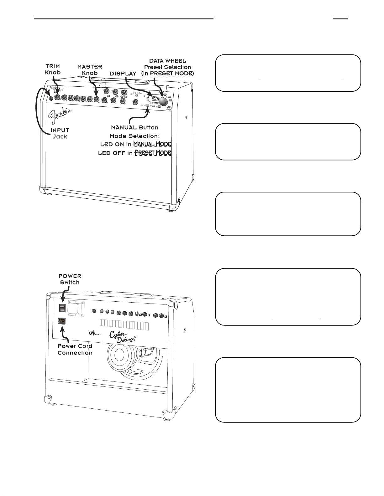
1) Make sure the POWER switch is OFF.
Connect both ends of the supplied power
cord—read Important Safety Instructions on
page 3. Plug your guitar into the INPUT jack.
2) Turn the MASTER level knob down to “1”;
switch the POWER ON. When “00.” appears
in the display, the Cyber–Deluxe™ amplifier is
ready to play in PRESET MODE.
3) While playing guitar, adjust the TRIM knob
until the adjacent green LED"#$is ON
most of the time and the red
LED
""#$$
flashes occasionally at peak
playing levels. Set MASTER to desired level.
4) Rotate the DATA WHEEL to explore other
Amp Design presets. Amplifier settings and
actual circuit configurations will change
automatically! (Note that while in PRESET
MODE, front panel knob positions may not
reflect actual amp settings until the knobs are
“captured”—see Overview Primer on page 8.)
5) The Cyber–Deluxe™ amplifier can also be
operated like a traditional amp. Turn the
MASTER level down, then press the MANUAL
button to release all preset control of amp
settings. In MANUAL MODE, knob positions
always reflect current settings—all green
capture LEDs are ON. Experiment with Reverb,
Modulation and Delay effects and have fun!
Page 8
wwwwww..ff ee nn ddeerr..ccoomm
✧
wwwwww
..mm rrggeeaarrhheeaa dd..nneett
6
Fender®Cyber–Deluxe™Amplifier
IIIInnnnttttrrrroooodddduuuuccccttttiiiioooonn
nn
Your new Cyber–Deluxe™ amplifier is brought to you by the same Tone–team that created the
Fender®Cyber–Twin™ amplifier. As the crowning achievements of Fender’s most advanced
research and development project, Cyber–Series™ amplifiers are endowed with Fender’s
exclusive
Virtual Tone Interpolation™
technology (patent number 6,222,110). VTI™ technology
enables the Cyber–Deluxe™ amplifier to be different amplifiers according to circuit design.
Starting with a virtual circuit board, the Cyber–Deluxe™ amplifier "rewires" its fundamental
architecture to become the essence of all the amplifier greats — Fender’s Blackface™,
Dyna–Touch™, Tweed and Modern amps, and even the best of the British amps!
The Cyber–Deluxe™ amplifier allows you to be the amp designer. Start with one of 32
permanent amp and effect setups stored within the Cyber-Deluxe™ amp—twist some knobs,
make some changes, then SAVE to one of the 32 rewritable preset locations reserved onboard
for your original amplifier designs. Or, press MANUAL and start from scratch. MIDI
implementation on the Cyber–Deluxe™ amplifier enables you to transfer presets to and from
the amp for backup to a PC, or for exchange with other Cyber–Deluxe™ amplifier players.
The Cyber–Deluxe™ amplifier also puts a huge array of studio–quality effects at your command:
Reverb, Modulation and Delay effects, enough to satisfy most any sonic appetite. And many
are in stereo, so you can use the line outputs, headphones, or an additional amp to enjoy a fully
ambient stereo dimension. The Cyber–Deluxe™ amplifier’s Dyna–Touch™ power amp circuitry
and Celestion®speaker deliver powerful, responsive Tone to you and your audience.
TT hhaa nn kk yy oo uu ff oo rr cc hh oo oo ss ii nngg FF eenn dd eerr ®®
—— TToo nn ee,, TTrr aadd ii tt ii oo nn aa nn dd II nnnn oovvaa ttii oo nn —— ss ii nncc ee 11 99 4466
Page 9

wwwwww..ff ee nn ddeerr..ccoomm
✧
wwwwww
..mm rrggeeaarrhheeaa dd..nneett
7
Fender®Cyber–Deluxe™Amplifier
CCCCyyyybbbbeeeerrrr––––DDDDeeeelllluuuuxxxxee
ee
™™
™™
AAAAmmmmpppplllliiiiffffiiiieeeerrrr FFFFeeeeaaaattttuuuurrrreeeess
ss
• 2 Performance MODES of amplifier configuration—automatic and manual:
••PRESET MODE: Access 64 Amp Design presets with the DATA WHEEL or remote foot– or MIDI–controller
••MANUAL MODE: Turn the knobs just as you would on a traditional guitar amp
• 64 Amplifier Design presets:
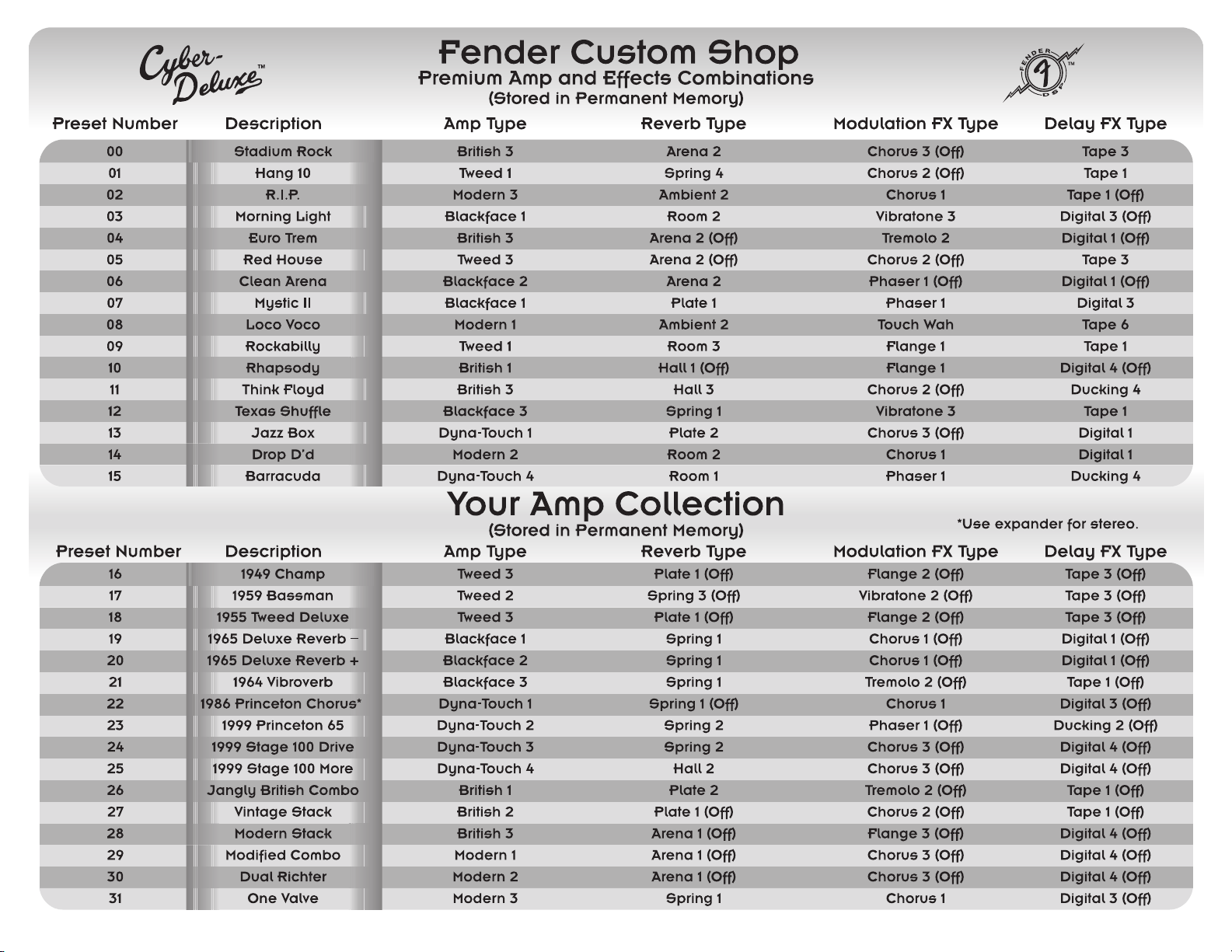
••32 Permanent presets – Great amp and effects setups that are always available
• 16 Fender®Custom Shop presets – Premium amp and effects combinations
• 16 presets in Your Amp Collection – “Stock” amplifiers
••32 Rewritable presets – Create and store your own amp and effects setups in the Player’s Lounge
• 3 Banks of studio–quality effects that can be used simultaneously:
••16 Reverb selections with LEVEL control and EDIT parameters
••16 Modulation effects selections with LEVEL control and EDIT parameters
••16 Delay effects selections with LEVEL control and EDIT parameters
• MIDI implementation:
••23 Continuous Controllers auto-adjust amp parameters for use with external MIDI equipment (sequencer,
computer, foot–controller or Cyber–Series™amplifier)
••1 Assignable Continuous Controller enables foot–pedal control of 1 of 12 programmable parameters
••System Exclusive functionality for selective preset management and individual system updates
• Virtual Tone Interpolation™ technology offers 8 Amp Type selections with tone stacks located before the
drive circuitry and 8 Amp Type selections with tone stacks located after the drive circuitry
• 4 Compression level settings
• 3 Noise Gate level settings each with an adjustable depth parameter
• On–board digital chromatic Tuner
• Expression Pedal (optional) provides real–time foot–control of any selected amp parameter—such as Volume
or Wah
• 4–button Footswitch (included) provides hands–free access to any 4 favorite presets
• 65 watts of output power
• 12˝, 8Ω Celestion®G12T–100 Speaker
• 1 Stereo/Mono EXPANDER Output jack (line level) with PHASE and LEVEL control—Create rich stereo sound
using onboard effects and any additional guitar amp
• 2 EFFECTS LOOP jacks with LEVEL switch for compatibility with rack–mount or stomp–box effects devices
• 2 Stereo/Mono SPEAKER SIMULATED LINE OUT jacks
Page 10
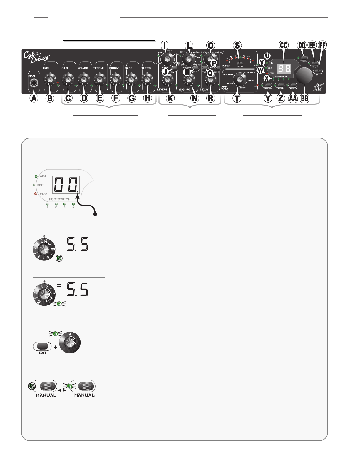
Overview Primer
P
RESET MODE
is active whenever the Cyber–Deluxe™ amplifier is first
switched ON. When a preset is selected (recalled), the amp is instantly
reconfigured to the settings saved within that preset. Presets can be
selected using the front panel DATA WHEEL (or 4–button footswitch or
by MIDI control). There are 32 preset locations (00.–31.) that are
permanent, as indicated by the decimal point in the display (Figure 1a).
There are 32 additional preset locations (32–63) that are rewritable for
your own amp and effects designs. As any preset is selected, the knob
positions usually will not reflect current amp parameter settings
(except when they match coincidentally). However, you can “capture”
control of any knob and use it to modify the sound of
the Cyber–Deluxe™ amplifier at any time.
To capture (acquire) control of a numbered level knob {C through H, K,
N, R}, simply turn it to match the stored preset value that appears in
the display as the knob is first moved (Figure 1b). An associated green
LED will come ON to indicate knob capture (Figure 1c), and the knob
position will then reflect its actual setting—and what is heard. Further
adjustments are audible, and the display updates the value in
real–time.
A pointer type knob {I, L, O, T} will capture immediately when turned.
Amp and effect types will change instantly from what is in the preset,
to what is indicated by the knob pointer. NOTE: To determine what
amp or effect type is stored within the current preset without changing
it, press and hold the EXIT button {FF} while turning the type knob until
its capture LED comes on—then release EXIT (Figure 1d).
Captured knobs (and their settings) are active temporarily. Save the
preset before selecting a different preset or switching to MANUAL MODE
(see SAVE on page 12).
M
ANUAL MODE
is activated by pressing the MANUAL button—the
adjacent green LED illuminates in M
ANUALMODE
(Figure 1e). Amplifier
settings are released from P
RESETMODE
control, and the front panel
knobs behave traditionally—all knobs are captured, as indicated by the
illumination of capture LEDs. To return to P
RESETMODE
, press the
MANUAL button again and the MANUAL LED will turn OFF.
wwwwww..ff ee nn ddeerr..ccoomm
✧
wwwwww
..mm rrggeeaarrhheeaa dd..nneett
8
Front Panel Overview
TTrraaddiittiioonnaall CCoonnttrroollss DDiiggiittaall EEffffeeccttss CCyybbeerr NNaavviiggaattiioonn
Fig. 1a
Fig. 1b
Fig. 1c
Fig. 1d
Fig. 1e
1
1
✧
✧
Over
Over
view
view
PRESET MODE MANUAL MODE
LED OFF LED ON
% Alternate between MODES by pressing
the MANUAL button.
%Hold EXIT and turn any pointer knob
until the LED illuminates to find the
preset amp or effect type.
% Turn a numbered knob to the preset
value to capture control of that
knob (LED is ON when captured).
% Nudge a numbered knob to display
the preset value (when LED is OFF).
%“Permanent preset” indicator
•
00.—31. are permanent
• 32—63 are rewritable
% Each preset contains a complete set
of amplifier and effects settings.
This section presents each of the knobs, buttons, jacks and LEDs as well
as an outline of the basic functionality of the Cyber–Deluxe™ amplifier.
Page 11
FFFFrrrroooonnnntttt PPPPaaaannnneeeellll OO
OOvvvveeeerrrrvvvviiiieeeewwww
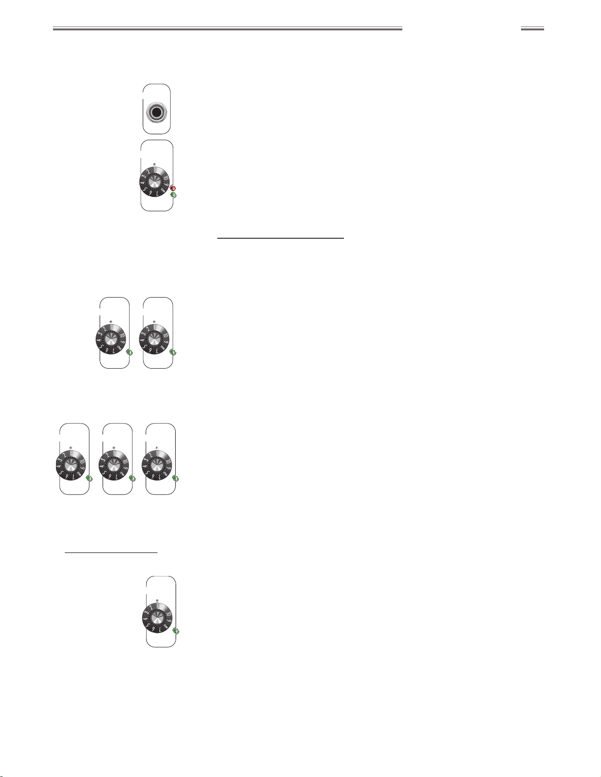
A. INPUT JACK
Input connection for your guitar.
B. TRIM
Sets the input signal level for proper analog–to–digital conversion. This
knob is always active, and does not have a capture LED (not preset
programmable). Adjust TRIM so the green LED is ON most of the time at
normal playing levels and the red LED flashes occasionally while playing at
peak intensity.
TTrraaddiittiioonnaall CCoonnttrroollss
When captured (LED ON), GAIN, VOLUME, TREBLE, MIDDLE, BASS and
MASTER knobs operate as they would on a traditional guitar amplifier.
C. GAIN
Controls the signal distortion level and contributes to overall amp loudness.
Use VOLUME {D} to adjust for (normalize) any undesired volume level
change resulting from a GAIN level change.
D. VOLUME
Controls the post–distortion signal level and contributes to overall amp
loudness. Use in conjunction with GAIN {C} to normalize volume
differences between presets.
E. TREBLE
Controls the high–frequency tone level.
F. MIDDLE
Controls the mid–frequency tone level.
G. BASS
Controls the low–frequency tone level.
H. MASTER VOLUME
Controls the overall volume output from the amplifier in conjunction with the
other level controls, TRIM {B}, GAIN {C}, and VOLUME {D}. MASTER
VOLUME is the final “gatekeeper” limiting the maximum output level of the
Cyber–Deluxe™ amplifier and the MASTER knob position sets that absolute
limit—even when controlling MASTER with an expression pedal or MIDI
messages. MASTER VOLUME is not preset programmable.
MASTER
% The location of the TREBLE,
MIDDLE and BASS tone controls
(either pre– or post–distortion), is
determined by the current
AMP TYPE {T} selection (see
Amp Type Selections on
page 16).
BASS
MIDDLE
TREBLE
GAIN
VOLUME
TRIM
INPUT
wwwwww..ff ee nn ddeerr..ccoomm
✧
wwwwww
..mm rrggeeaarrhheeaa dd..nneett
9
Front Panel Overview
Page 12
wwwwww..ff ee nn ddeerr..ccoomm
✧
wwwwww
..mm rrggeeaarrhheeaa dd..nneett
10
Front Panel Overview
DDiiggiittaall EEffffeeccttss
The 3 effects groups have similar functions outlined below {I through R}.
See Effects Editing, starting on page 19 for detailed editing operations.
I. REVERB SELECTION
Selects from 16 variations of 6 Reverb types.
J. REVERB EDIT
Selects a Reverb parameter to edit.
K. REVERB LEVEL
Adjusts the Reverb level.
L. MODULATION EFFECTS SELECTION
Selects from 16 variations of 6 Modulation effect types.
M. MODULATION EFFECTS EDIT
Selects a Modulation effect parameter to edit.
N. MODULATION EFFECTS LEVEL
Adjusts the Modulation effect level.
O. DELAY EFFECTS SELECTION
Selects from 16 variations of 3 Delay effect types.
P. DELAY EFFECTS EDIT
Selects a Delay effect parameter to edit.
Q. DELAY EFFECTS TAP
Provides an intuitive way to rhythmically set the Delay time interval, simply
by tapping in the desired tempo. The adjacent green LED flashes to the
interval.
R. DELAY EFFECTS LEVEL
Adjusts the Delay effect level.
DELAY
DUCKING
TAPE
TAP
EDIT
DIGITAL
MOD. F/X
VIBRATONE
CHORUS
PHASER
WAH
TREMOLO
FLANGE
T
P
EDIT
REVERB
AMBIENT
HALL
ROOM
SPRING
ARENA
PLATE
EDIT
TTrraaddiittiioonnaall CCoonnttrroollss DDiiggiittaall EEffffeeccttss CCyybbeerr NNaavviiggaattiioonn
Page 13
wwwwww..ff ee nn ddeerr..ccoomm
✧
wwwwww
..mm rrggeeaarrhheeaa dd..nneett
11
Front Panel Overview
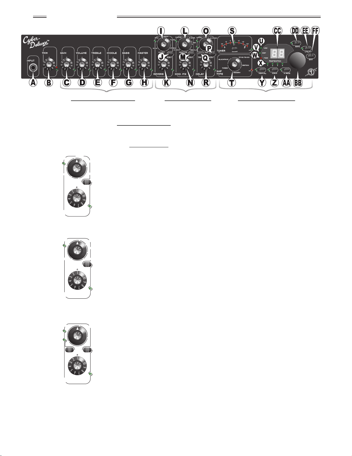
CCyybbeerr NNaavviiggaattiioonn
S. TUNER ON/OFF
Activates/deactivates the Tuner. When the Tuner is ON, the green “ON” LED
illuminates and audio output is muted. Tune your guitar by striking a single
string. The note closest to that played will appear in the display. Only
sharps (#) are indicated, so for example, D-flat will appear as “Cª” (C-sharp)
in the display. Watch the arc of Tuner LEDs while tuning a string—when the
green center LED is ON, the string is properly tuned to the displayed note.
The red LEDs indicate approximately how much in “cents” the string is out
of tune. (There are 100 cents between adjacent semi-tones.)
T. AMP TYPE
Selects from 16 variations of 5 amplifier types. Clockwise selections within
each AMP TYPE increase Gain and response from clean to overdriven, as
illustrated. Specific characteristics of each variation are detailed in the next
section (see the Amp Type Selections on page 16).
NOTE: Presets will have several amplifier parameters optimized for their
specific Amp Type settings. Changing the Amp Type could result in sudden
tonal and/or volume changes. This is easily remedied by readjusting Gain,
Volume and Tone settings.
U. MIDI LED
Indicates MIDI activity. This green LED flashes while the Cyber-Deluxe™
amplifier is transmitting or receiving MIDI information.
V. EDIT LED
Indicates when editing has been initiated by pressing the COMP button {Z},
the N GATE button {AA}, or any of the effects EDIT buttons {J, M, P}. When
the EDIT LED is blinking, the Cyber–Deluxe™ amplifier is waiting for
user–input via the DATA WHEEL {BB}.
W. PEAK LED
Indicates when the digital signal is clipping (distorting). If undesirable
distortion is heard while the red PEAK LED is flashing, reduce the VOLUME
{D} level and double–check the TRIM {B} setting.
X. FOOTSWITCH SELECTION LEDs
Indicate when the current preset is assigned to any of the 4 footswitch
buttons (see FOOTSWITCH JACK on page 13).
Y. MANUAL
Toggles between M
ANUALMODE
and P
RESETMODE
. When M
ANUALMODE
is
selected, the adjacent green LED is ON, and “– –” is displayed indicating
that the audible sound is not associated with any specific preset.
Z. COMPRESSOR
Accesses Compressor settings for the current preset (or while in M
ANUAL
M
ODE
). Press once, then use the DATA WHEEL {BB} to select from
4 compression settings, or to turn the Compressor OFF. The adjacent green
LED is ON anytime the Compressor is active. Press EXIT {FF} when
selection is complete. See Compressor Settings on page 23.
% TRIM {B} level should be set
properly for optimal Tuner
performance (see TRIM on
page 9).
Page 14

wwwwww..ff ee nn ddeerr..ccoomm
✧
wwwwww
..mm rrggeeaarrhheeaa dd..nneett
12
Front Panel Overview
AA. NOISE GATE
Accesses Noise Gate settings for the current preset (or while in M
ANUAL
M
ODE
). Press once, then use the DATA WHEEL {BB} to select from 3 Noise
Gate types, or to turn the Noise Gate off. Press the button a second time
to adjust the depth from 1.0 to 9.9. The adjacent green LED will be ON any
time the Noise Gate is active. Press EXIT {FF} when selection/adjustment
is complete. See Noise Gate Settings on page 23.
BB. DATA WHEEL
• Selects presets when the Cyber–Deluxe™ amplifier is in P
RESETMODE
• Sets values when editing Compressor, Noise Gate or effects parameters
• Set assignments for most Utility functions
CC. DISPLAY SCREEN
• Displays the current preset number in P
RESETMODE
• Displays “— —” in M
ANUALMODE
• Displays the closest note to that being played while using the Tuner
• Displays the value of most knob settings as they are adjusted
• Displays the mnemonic code (abbreviation) for parameters and their
numeric values when an EDIT button {J, M or P} is pressed
DD. SAVE
Saves the current amplifier configuration to memory:
1) Press SAVE once and the display will flash a rewritable preset location.
2) Select any rewritable preset location (32–63) using the DATA WHEEL {BB}.
3) Press SAVE again and the preexisting contents of the displayed preset
location will be overwritten with the current amplifier configuration.
NOTE: If a different preset is selected before the current configuration is
saved, any active changes are lost.
EE. UTILITY
Accesses Utility settings for:
• MIDI/System management (see Utility Menu Functions on page 25)
• 4–button Footswitch—Preset Assignment (see page 25)
• Expression Pedal—Parameter Assignment (see page 26)
The adjacent green LED will be ON while navigating through the Utility
menu. Press EXIT {FF} when selections are complete.
FF. EXIT
Returns the Cyber-Deluxe™ amplifier to the most recent play mode (P
RESET
or M
ANUAL
) after using the Tuner and after editing effects, Compressor,
Noise Gate or Utility parameters. (EXIT will also return the amplifier to
P
RESETMODE
from M
ANUALMODE
.)
% Use SAVE to COPY any of the 64
presets, with or without
modifications, to a rewritable
preset location (32–63).
% The red SAVE LED always flashes
in MANUAL MODE and after any
parameter is modified in PRESET
MODE as a reminder to SAVE.
Page 15

wwwwww..ff ee nn ddeerr..ccoomm
✧
wwwwww
..mm rrggeeaarrhheeaa dd..nneett
13
Rear Panel Overview
GG. POWER
Switches Power ON or OFF to the Cyber–Deluxe™ amplifier.
HH. IEC POWER CORD SOCKET
Connection for the included power cord. Connect to a grounded AC outlet
in accordance with the voltage and frequency rating listed on the rear panel
of the unit.
II. EXPRESSION PEDAL JACK
Connection for a standard expression foot pedal (optional) used to remotely
control the function of any front panel numbered knob, except for TRIM {B}.
It can also be assigned to control the primary Reverb, Modulation or Delay
effect parameter. The assignment is preset programmable (see Expression
Pedal—Parameter Assignment on page 26).
JJ. FOOTSWITCH JACK
Connection for the included Fender®4–button footswitch used to access
four favorite presets hands-free. The front panel footswitch LEDs {X}
indicate active footswitch buttons (see 4–Button Footswitch—Preset
Assignment on page 25).
NOTE: For best results, use the supplied 5-pin DIN cable for connection.
Use of some MIDI–type cables can cause erratic footswitch operation.
RRRReeeeaaaarrrr PPPPaaaannnneeeellll OO
OOvvvveeeerrrrvvvviiiieeeewwww
Page 16

wwwwww..ff ee nn ddeerr..ccoomm
✧
wwwwww
..mm rrggeeaarrhheeaa dd..nneett
14
Rear Panel Overview
KK. MIDI IN PORT
Standard MIDI connection used to receive data from an external MIDI
device (see MIDI Capabilities on page 27).
LL. MIDI OUT PORT
Standard MIDI connection used to transmit data to an external MIDI device
(see MIDI Capabilities on page 27).
MM. HEADPHONES JACK
Connection for headphones using a standard 1/4˝ stereo phone plug. Use
of this jack automatically mutes the Cyber–Deluxe™ amplifier speaker and
EXPANDER jack {QQ}. This stereo output incorporates speaker simulation
circuitry to produce sound similar to that of miked guitar amp speakers
(compensating for the frequency response of headphones).
Cable Type and Signal Quality
NOTE: Jacks NN, QQ, SS and TT are all impedance balanced TRS
(Tip–Ring–Sleeve) connections, with (+) on tip and (-) on ring. Using
standard TS (Tip–Sleeve) mono guitar cords with these jacks is acceptable,
but the use of 3-conductor (stereo-type) TRS cords could significantly
improve sound quality (signal/noise ratio) in certain situations.
NN. LINE OUT JACKS
Line–level stereo output connections for use with sound reinforcement and
recording equipment. These outputs also incorporate speaker simulation
circuitry. For (summed) mono output, use only the L/MONO jack.
Page 17

wwwwww..ff ee nn ddeerr..ccoomm
✧
wwwwww
..mm rrggeeaarrhheeaa dd..nneett
15
Rear Panel Overview
OO. EXPANDER LEVEL
Balances the signal level sent to an external guitar amplifier connected to
the EXPANDER jack {QQ}, to compensate for differences in apparent
volume output.
PP. EXPANDER PHASE SWITCH
Reverses the phase of the signal at the EXPANDER jack {QQ}, which could
improve the overall sound when the expander function is used with certain
other guitar amplifiers. Select the switch position that sounds the best.
QQ. EXPANDER LINE OUT JACK
Line–level output connection for use in a mono or stereo expansion
configuration. Connect to the power amp input, or the line–in jack on
another guitar amplifier. This output does not incorporate speaker
simulation circuitry and therefore will sound best linked to a guitar amplifier,
rather than a bass or keyboard amplifier or full-range PA system.
RR. EXPANDER MONO/STEREO SWITCH
Selects either MONO or STEREO RIGHT CHANNEL output for the
EXPANDER jack {QQ}. When this switch is OUT, both the internal speaker
and the EXPANDER jack produce a (summed) MONO signal. When this
switch is IN, the internal speaker produces the LEFT stereo channel, and the
expansion amplifier/speaker produces the RIGHT stereo channel. NOTE:
The Cyber–Deluxe™ amplifier speaker will always produce a summed
MONO signal, regardless of switch position, when the EXPANDER jack is
not used.
SS. EFFECTS LOOP SEND JACK
Output for connection to the input jack of an external effects device.
TT. EFFECTS LOOP RETURN JACK
Input for connection from the output jack of an external effects device.
UU. EFFECTS LOOP LEVEL SWITCH
A 2–position switch for setting compatibility with effects devices:
• Switch OUT (–10dBV) for use with most foot pedal type effects
• Switch IN (+4dBu) for use with most professional rack-mounted effects
Page 18

wwwwww..ff ee nn ddeerr..ccoomm
✧
wwwwww
..mm rrggeeaarrhheeaa dd..nneett
16
Presets In–Depth
2
2
✧
✧
Pr
Pr
esets In–Depth
esets In–Depth
AAAAmm
mmpppp TTTTyyyyppppeeeessss &&&& EEEEffffffffeeeeccccttttssss
DD
DDeeeeffffiiiinnnneeeedddd
The following 4 tables offer definitions for Amp Type Selections and Effects
Selections—essential components of each preset. This information is useful
when designing a preset or selecting one to play.
Amp Type Selections
The AMP TYPE pointer knob selects variations of 5 fundamental amp circuitry
types. The characteristics of each variation are described in the following table:
AMP TYPE SELECTION GAIN GENERAL DESCRIPTION TONE CONTROL LOCATION
1 CLEAN
TWEED 2 CRUNCH Tweed–era with ‘59 Bassman
®
amplifier tone controls PRE–DISTORTION
3HIGH
1 CLEAN
BLACKFACE 2 CRUNCH Vintage Fender
®
Blackface™amplifier tone controls PRE–DISTORTION
3HIGH
1 CLEAN PRE–DISTORTION
2HIGH
3 HIGHER
4 MAX
1 CRUNCH Jangly British combo PRE–DISTORTION
BRITISH 2 HIGH Vintage British stack
3 HIGHER Modern British stack
1 Modified combo
MODERN 2 MAX Heavy Metal stack POST–DISTORTION
3 Heavy Metal combo
NOTE: Presets will have several amplifier parameters optimized for their specific Amp
Type settings. Changing the Amp Type could result in sudden tonal and/or volume
changes. This is easily remedied by readjusting Gain, Volume, and Tone settings.
DYNA-TOUCH
Direct from the Fender®Dyna–Touch™series amplifiers
POST–DISTORTION
POST–DISTORTION
Page 19

wwwwww..ff ee nn ddeerr..ccoomm
✧
wwwwww
..mm rrggeeaarrhheeaa dd..nneett
17
Presets In–Depth
MOD F/X Selections
The MOD. F/X pointer knob selects variations of 6 Modulation effect types.
The characteristics of each variation are described in the following table:
REVERB TYPE SELECTION GENERAL DESCRIPTION ADDITIONAL NOTES
1 Very small space with typical brightness
2 Small space with darker frequency response
1 Dark sounding room with short decay
ROOM 2 Bright room with medium decay Simulates the reverberation of a small room
3 Dark room with medium decay
1 Dark sounding hall with medium decay
HALL 2 Bright concert hall with medium decay Simulates the sound of auditoriums and concert halls
3 Medium–bright hall with long decay
1 Dark frequency response with long decay
2 Bright frequency response with long decay
1 Medium–bright plate response Simulates a recording studio plate reverb system with bright, yet
2 Bright plate response with long decay warm timbres
1 Medium–bright Blackface
™
Reverb Typical Blackface™era Reverb used on models such as the
2 Bright Blackface™ Reverb with longer decay ‘65 Twin Reverb
®
and ‘65 Deluxe Reverb®amplifiers
3 Dark '63 Fender
®
Reverb Unit with long decay Simulates the sound and pre–drive circuitry connection of an
4 Bright '63 Fender
®
Reverb Unit with long decay original ‘63 Fender®Reverb Unit
FX TYPE SELECTION GENERAL DESCRIPTION ADDITIONAL NOTES
1 Slow sweep rate with high depth
CHORUS 2 Medium sweep rate with high depth Lush chorus effect with smooth triangle wave LFO delay modulation
3 Fast sweep rate with low depth
1 Slow sweep rate with medium depth
FLANGE 2 Slow sweep rate with high depth Deep flange effect with smooth triangle wave LFO delay modulation
3 Fast sweep rate with medium depth
1 Medium sweep rate with medium depth
2 Fast sweep rate with low depth and feedback
1 (Touch) Wah effect that responds to playing strength Wide–range dynamic touch–control
2 (Pedal) Foot–pedal controlled Wah effect Faithful reproductions of two popular Wah pedals
1 Medium–fast rate with high duty cycle
TREMOLO 2 Fast rate with high depth
3 Fast rate with medium–high depth and duty cycle
1 Slow rate with medium depth
VIBRATONE 2 Fast rate with high depth
3 Fast rate with medium depth
Effects Selections
REVERB Selections
The REVERB pointer knob selects variations of 6 Reverb types.
The characteristics of each variation are described in the following table:
PHASER
WAH
Twelve–stage stereo phase shifter effect
A Tremolo effect with the sound of a vintage Fender
®
Blackface™
amplifier, with adjustable high/low volume ratios
Faithful reproduction of the CBS
®
–era Fender®Vibratone rotating
speaker cabinet
AMBIENT
ARENA
PLATE
SPRING
Simulates the sound of a very small acoustic space
Simulates the sound of a large arena
Page 20

wwwwww..ff ee nn ddeerr..ccoomm
✧
wwwwww
..mm rrggeeaarrhheeaa dd..nneett
18
Presets In–Depth
DELAY TYPE SELECTION GENERAL DESCRIPTION ADDITIONAL NOTES
1 130ms delay, low feedback, medium wow & flutter
2 120ms delay, high feedback, medium–high wow & flutter
3 300ms delay, low feedback, medium wow & flutter
4 450ms delay, low feedback, low wow & flutter
5 600ms delay, low feedback, medium–high wow & flutter
6 650ms delay, low feedback, high wow & flutter
1 100ms delay, medium feedback, bright repeats (panning)
2 230ms delay, single repeat (panning)
3 400ms delay, low feedback (panning)
4 460ms delay, medium feedback, bright repeats (panning)
5 800ms delay, medium feedback, dark repeats (panning)
6 1.4 second medium feedback, bright repeats (panning)
1 220ms delay, medium feedback, high ducking
2 350ms delay, medium–high feedback
3 460ms delay, medium feedback
4 650ms delay, medium feedback, high ducking
DELAY Selections
The DELAY pointer knob selects variations of 3 Delay effect types.
The characteristics of each variation are described in the following table:
TAPE
DIGITAL
DUCKING
Convincing simulation of vintage tape delay, with adjustable
wow & flutter (random frequency response and pitch variations)
Stereo - Digital delay with auto–panning that can be heard
when using headphones, both LINE OUTPUT jacks, or second
amplifier plugged into the EXPANDER jack
Repeating delays duck (drop to the background) while you are
playing to reduce audio overlap or “muddiness”—the delay tail
comes to the foreground when you stop playing
Page 21

wwwwww..ff ee nn ddeerr..ccoomm
✧
wwwwww
..mm rrggeeaarrhheeaa dd..nneett
19
Presets In–Depth
PPPPrrrreeeesssseeeetttt EEEEddddiiiitttt MMMMeeeennnnuuuussss
This section explains how to edit preset parameters that are within menus.
The edit process:
1) Access a parameter (menu item) using a button listed
below, 2) Edit the parameter value using the DATA WHEEL, 3) Press EXIT,
4) Save the edited preset using the procedure on page 12, if desired.
Parameters for: Button How to Edit
Reverb . . . . EDIT {J} . . . . . . . . . See page 20
Modulation effects . . . . EDIT {M}. . . . . . . . . See page 20
Delay effects . . . . EDIT {P} . . . . . . . . . See page 22
Compressor . . . . COMP {Z} . . . . . . . . See page 23
Noise Gate . . . . N GATE {AA}. . . . . . See page 23
Expression pedal . . . . UTILITY {EE}. . . . . . See page 26
Effects Editing
You can access parameters for the currently selected effect in each effects
group by pressing the EDIT button one or more times. You can then edit the
parameter value by turning the DATA WHEEL.
When an EDIT button is pressed, a two letter parameter code and the
parameter’s current value are alternately displayed. The green EDIT LED
also flashes until editing has ended.
After editing one or more parameter values with the DATA WHEEL, press
EXIT to end the edit process. Ending the edit process will keep your
changes active . . . Save your changes to a new preset to secure them.
The EDIT parameters for REVERB, MOD. F/X and DELAY effects groups are
covered on the next 3 pages. Normally, the EDIT button will access one
parameter for each REVERB and MOD. F/X and 2 parameters for DELAY,
but in the Advanced Edit Mode you have access to 4 parameters for each
effects group selection (see Advanced Edit Mode, below).
Advanced Edit Mode
To enable the Advanced Edit Mode: Turn the amplifier OFF. Press and hold
in the three EDIT buttons {J, M and P}, then turn the amplifier ON. Release
the EDIT buttons after the display lights up. Now each of the EDIT buttons
will incrementally access 4 parameters.
To disable the Advanced Edit Mode: Turn the Cyber-Deluxe™ amplifier OFF
and ON again.
% Generally, it is unnecessary to edit the
additional parameters of Advanced Edit
Mode. The most commonly adjusted
parameter settings are always
accessible using the EDIT buttons.
%Parameter “code” and parameter
“value” alternately display when any
EDIT button is pressed.
% EDIT operations automatically return
the amp to the play mode after 45
seconds of inactivity.
VIBRATONE
CHORUS
PHASER
WAH
TREMOLO
FLANGE
T
P
EDIT
DUCKING
TAPE
MONO
TAP
EDIT
AMBIENT
HALL
ROOM
SPRING
ARENA
PLATE
EDIT
Page 22

AMBIENT, ROOM, HALL, ARENA, PLATE, SPRING
Time (ti) Length of time (duration) that the Reverb sustains (1.0 is shortest, 9.9 is longest)
Dwell (dL) Signal level going into the Reverb (versus output level controlled by the numbered REVERB knob). (1.0 is minimum, 9.9 is maximum)
Diffusion (dF) Density of the Reverb from sparse with non–uniform decay, to dense with smooth decay (1.0 is sparsest, 9.9 is smoothest)
Tone (tn) Brightness of the Reverb signal (1.0 is darkest, 9.9 is brightest)
wwwwww..ff ee nn ddeerr..ccoomm
✧
wwwwww
..mm rrggeeaarrhheeaa dd..nneett
20
Presets In–Depth
Reverb – Edit Menu
The parameters Time, Dwell, Diffusion and Tone apply to all 6 Reverb types.
Reverb Time is always accessible to edit by pressing the Reverb EDIT
button. The shaded parameters in the figure and table below, are
accessible only in Advanced Edit Mode (see page 19). Edit parameter
values with the DATA WHEEL (range is 1.0 to 9.9).
Figure 2a
Reverb Edit Menu
% Figures 2a, 2b and 2c illustrate EDIT
button operation by showing for each
press in turn, the menu item
(parameter code) as it appears in the
display, and the parameter name.
Modulation Effects – Edit Menu
The unshaded parameters in Figure 2b (and the associated tables) are
always accessible to edit for the currently selected effect, by pressing the
Mod. F/X EDIT button. The shaded parameters are accessible only in
Advanced Edit Mode (see page 19). Edit parameter values with the DATA
WHEEL (range is 1.0 to 9.9 for most parameters).
Figure 2b
Modulation Effects
Edit Menu
% Pedal Wah requires the use of either an
expression pedal or MIDI pedal to
control the Wah effect (see page 26).
Reverb Parameter Descriptions
Page 23

CHORUS
Rate (rt) Sweep rate of the Chorus effect (0.08 Hz displayed as 1.0 is slowest, 10 Hz displayed as 9.9 is fastest)
Depth (dP) Amount of Doppler frequency shift and how apparent the Chorus effect sounds (1.0 is minimum effect, 9.9 is maximum effect)
Average Delay Time (dt) Average delay time of the moving Chorus taps (repeats), use higher settings for doubling effect (1.0 is shortest, 9.9 is longest)
Left/Right Phase
1
(Ph) Stereo - Phase between left and right channel low frequency oscillators (1.0 is minimum stereo effect, 9.9 is maximum stereo effect)
FLANGE
Rate (rt) Sweep rate of the Flange effect (0.08 Hz displayed as 1.0 is slowest, 10 Hz displayed as 9.9 is fastest)
Depth (dP) Amount of Doppler frequency shift and how apparent the Flange effect sounds (1.0 is minimum effect, 9.9 is maximum effect)
Feedback (Fb) Amount of Flange effect processed signal that is fed back (recycled) to the input (1.0 is minimum feedback, 9.9 is maximum feedback)
Left/Right Phase
1
(Ph) Stereo - Phase between left and right channel low frequency oscillators (1.0 is minimum stereo effect, 9.9 is maximum stereo effect)
PHASER
Rate (rt) Sweep rate of the Phaser effect (0.08 Hz displayed as 1.0 is slowest, 10 Hz displayed as 9.9 is fastest)
Depth (dP) Width of the Phaser sweep – corresponds to how apparent the Phaser effect sounds (1.0 is minimum effect, 9.9 is maximum effect)
Feedback (Fb) Amount of Phaser effect processed signal that is fed back (recycled) to the input (1.0 is minimum feedback, 9.9 is maximum feedback)
Stereo Spread
1
(St) Stereo - Amount of stereo separation between left and right channels (1.0 is minimum stereo effect, 9.9 is maximum stereo effect)
Touch WAH
Sensitivity (SE) Sensitivity of the Wah effect to your playing volume (signal strength) (1.0 is least reactive, 9.9 is most reactive)
Minimum Frequency (LO) Frequency the Wah relaxes to when your playing volume is at minimum (1.0 is lowest frequency, 9.9 is highest frequency)
Maximum Frequency(HI) Frequency the Wah sweeps to when your playing volume is at maximum (1.0 is lowest frequency, 9.9 is highest frequency)
Wah Sweep ( SP) Two Wah sweep types: Low–Q (Lo) is smooth, High–Q (Hi) is extreme
Pedal WAH
Center Frequency (Fr) The center frequency of the Wah filter (1.0 is lowest, 9.9 is highest)
Heel Frequency ( HE) The heel–down Wah frequency (1.0 is lowest, 9.9 is highest)
Toe Frequency (to) The toe–down Wah frequency (1.0 is lowest, 9.9 is highest)
Wah Sweep ( SP) Two Wah sweep types: “The Baby’s Cryin’” (Cr) is modern, “The Real McQ” (rL) is vintage
TREMOLO
Rate (rt) Cycle rate of the Tremolo effect (0.08 Hz displayed as 1.0 is slowest, 10 Hz displayed as 9.9 is fastest)
Depth (dP) Amount the volume level drops with each cycle of the Tremolo effect (1.0 is minimum depth, 9.9 is maximum depth)
Duty–Cycle (dC) Ratio of the high–volume to low–volume intervals in duration (1.0 is shorter high–volume intervals, 9.9 is longer high–volume intervals)
Release Filter (rF) Smoothness of the Tremolo waveform (1.0 is subtle and natural, 9.9 is choppy and percussive)
VIBRATONE
Rotor Speed (rt) Rate of the virtual rotating speaker baffle (0.08 Hz displayed as 1.0 is slowest, 10 Hz displayed as 9.9 is fastest)
Doppler Frequency Shift (dF) Amount of Doppler frequency shift and how apparent the Vibratone effect sounds (1.0 is minimum effect, 9.9 is maximum effect)
Low-Pass Filter Range (LP) Amount of high frequencies in the Vibratone signal (1.0 is minimum highs (dark tone), 9.9 is maximum highs (bright tone))
Amplitude Modulation Depth (dP) Amount the volume level varies with each cycle of the Vibratone effect (1.0 is minimum effect, 9.9 is maximum effect)
wwwwww..ff ee nn ddeerr..ccoomm
✧
wwwwww
..mm rrggeeaarrhheeaa dd..nneett
21
Presets In–Depth
1
This parameter modifies the stereo capabilities of your Cyber–Deluxe™ amplifier which can be enjoyed using a dual amplifier configuration, through headphones or by using the
stereo line outputs.
Modulation Effects Parameter Descriptions
Page 24

wwwwww..ff ee nn ddeerr..ccoomm
✧
wwwwww
..mm rrggeeaarrhheeaa dd..nneett
22
Presets In–Depth
Delay Effects – Edit Menu
The parameters Delay Time and Feedback are always accessible to edit
by pressing the Delay EDIT button 1 or 2 times respectively. The
shaded parameters in the figure and tables below are available only in
Advanced Edit Mode (see page 19). Edit parameter values with the
DATA WHEEL (range is 1.0 to 9.9, except for Delay Time which ranges
from 0.3 to 14 (30 to 1450 milliseconds)).
Delay Time can also be set by feel with the TAP button (see DELAY
EFFECTS TAP on page 10).
% Displayed values for delay times:
Multiply displayed value by 100 to
calculate the approximate delay time in
milliseconds. Note that the DATA
WHEEL continues to increment the
delay time slightly past the maximum
displayed value of 14 for a maximum
delay time of 1450ms.
Figure 2c
Delay Effects Edit Menu
TAPE
Delay Time (dt) Duration between delay repeats from 30 milliseconds (0.3) to about 1450 milliseconds (14)
Feedback (Fb) Number of delay repeats (1.0 is 1 repeat, 9.9 is many repeats)
Wow & Flutter (FL) Amount of random volume and pitch changes – tape recorder nostalgia effect (1.0 is minimum fluctuation, 9.9 is maximum fluctuation)
Low-Pass Frequency Cutoff (LP) Brightness of the delay signal (1.0 is minimum (dark tone), 9.9 is maximum brightness)
DIGITAL
Delay Time (dt) Duration between delay repeats from 30 milliseconds (0.3) to about 1450 milliseconds (14)
Feedback (Fb) Number of delay repeats (1.0 is 1 repeat, 9.9 is many repeats)
Low-Pass Frequency Cutoff (LP) Brightness of the delay signal (1.0 is minimum (dark tone), 9.9 is maximum brightness)
Input Level (in) Signal level going into the delay effect (versus output level controlled by the numbered DELAY knob) (1.0 is minimum, 9.9 is maximum)
DUCKING
Delay Time (dt) Duration between delay repeats from 30 milliseconds (0.3) to about 1450 milliseconds (14)
Feedback (Fb) Number of delay repeats (1.0 is 1 repeat, 9.9 is many repeats)
Release Time (rL) Time the Ducking effect waits before returning the background delay repeat volume to normal (1.0 is shortest wait, 9.9 is longest wait)
Ducking Threshold ( th) Sensitivity of the Ducking action to your playing strength (signal level) (1.0 in least reactive, 9.9 is most reactive)
Delay Effects Parameter Descriptions
Page 25

wwwwww..ff ee nn ddeerr..ccoomm
✧
wwwwww
..mm rrggeeaarrhheeaa dd..nneett
23
Presets In–Depth
Compressor Settings
The function of the Compressor is to moderate signal level for a constant,
steady output by boosting a fading signal level and limiting an excessive
signal level. It is often used to increase the sustain of held notes in guitar
solos, and to avoid overpowering any other instruments with rhythm guitar.
The Cyber–Deluxe™ amplifier offers 4 levels of signal compression (see
COMPRESSOR on page 11).
Noise Gate Settings
The function of the Noise Gate is to reduce noise when the guitar input level
is near zero (noise is picked up from environmental sources such as
fluorescent light fixtures). The Cyber–Deluxe™ amplifier offers 3 levels of
Noise Gate; low, medium, and high. Each level has an adjustable depth
parameter accessed with a second press (see NOISE GATE on page 12).
% It is generally best to use the lowest
settings necessary to achieve
satisfactory results when adjusting the
Compressor and Noise Gate.
Page 26

wwwwww..ff ee nn ddeerr..ccoomm
✧
wwwwww
..mm rrggeeaarrhheeaa dd..nneett
24
Advanced Functions
3
3
✧
✧
Advanced Functions
Advanced Functions
This section discusses system configuration options and the MIDI features
of the Cyber-Deluxe™amplifier.
Stereo Expander – Auxiliary Amplifier Set-Up
Fully experience the stereo effects onboard the Cyber–Deluxe™ amplifier
using the Stereo Expander feature. Any second guitar amp, such as a
Fender®Princeton®65 amplifier, can be used, see Figures 3a and 3b below.
1) Switch POWER OFF to both amplifiers.
2) Turn the EXPANDER LEVEL knob {OO} fully counterclockwise.
3) Connect the amplifiers, EXPANDER jack {QQ} to the auxiliary amp’s
POWER AMP IN or EFFECTS RETURN jack, using a guitar/patch cord
(tip–sleeve (TS) and tip–ring–sleeve (TRS) type cords are acceptable).
4) Set the EXPANDER MONO/STEREO button {RR} to the IN position.
5) Switch POWER ON to the Cyber–Deluxe™ amplifier, then the auxiliary amp.
6) While playing with your guitar and Cyber–Deluxe™ amplifier at normal
levels, turn the EXPANDER LEVEL knob {OO} until the amplifiers are
equally loud. If any auxiliary amp controls are functional, it may be
necessary to adjust them to achieve a balance in volume and tone.
7) Toggle the EXPANDER PHASE {PP} switch IN and OUT to determine if
either setting improves the stereo effect. This feature corrects the phase
differences that could exist between various amplifier models.
Figure 3b
Stereo Amp Positioning
%
Separate the amplifiers and
balance their loudness levels for a
full stereo effect.
%
Most, or all panel controls on an
auxiliary amplifier are usually
bypassed when connecting directly
to the power amp input.
Figure 3a
Stereo Expander Connection
Cyber–Deluxe
™
Amplifier
“Auxiliary”
Amplifier
Page 27

wwwwww..ff ee nn ddeerr..ccoomm
✧
wwwwww
..mm rrggeeaarrhheeaa dd..nneett
25
Advanced Functions
Utility Menu Functions
All configuration settings in the Utility menu are global to the amp operating
system (independent of the presets), with one exception. Expression Pedal
parameter assignment is saved as part of each preset.
Press the UTILITY button 1 or more times to access each of the Utility menu
items shown in Figure 3c below. Edit/execute menu items using the
appropriate ACTIVATION CONTROL.
NOTE: For all Utility menu operations, the number of presses specified
assumes that you are starting the operation from the normal play mode
(press EXIT if necessary to return to play mode). You can edit multiple Utility
settings before leaving the menu. Items are accessed in a continuous loop,
incrementing with UTILITY presses.
For a table of Utility menu default values and selection ranges, refer to
Appendix 1 on page 31. For information on MIDI messages and preset edit
tables, refer to Appendix 2 through Appendix 5 starting on page 32.
4–Button Footswitch – Preset Assignment
You can store four favorite presets for quick access from the 4–button
Footswitch.
1) Select the preset you would like to assign to a Footswitch button using
the DATA WHEEL (make it the active preset).
2) Press UTILITY once and “Ft” will be displayed. All FOOTSWITCH LEDs will
flash (except any that are already assigned to the current preset, in which
case the LED will stay ON without flashing).
3) Select a Footswitch button (1,2,3,4) and store the assignment.
a) Turn the DATA WHEEL to illuminate the desired FOOTSWITCH LED,
then press the TAP button, OR
b) Press the selected Footswitch button directly.
NOTE: For best results, use the supplied 5-pin DIN cable for connection.
Use of some MIDI–type cables can cause erratic footswitch operation.
%
To access Utility menu items more
rapidly (or in reverse order), press and
hold the UTILITY button while rotating
the DATA WHEEL.
Figure 3c
Utility Menu Items
Page 28

wwwwww..ff ee nn ddeerr..ccoomm
✧
wwwwww
..mm rrggeeaarrhheeaa dd..nneett
26
Advanced Functions
Expression Pedal – Parameter Assignment
One Utility menu item, Expression Pedal - Parameter Assignment, is saved
within each preset. Any of the parameters listed in step 2 below can be
assigned to an expression pedal (optional) for remote control. This
operation also assigns the same parameter to Continuous Controller #11
(for MIDI pedal control).
1) Press UTILITY repeatedly until “Pd” is displayed. A capture LED will light
up to indicate the current assignment.
2) Turn the DATA WHEEL to select from the following parameters:
Numbered knobs—
• GAIN ...........Level • MIDDLE ......Level • REVERB .....Level
• VOLUME .....Level • BASS ..........Level • MOD F/X ....Level
• TREBLE.......Level • MASTER .....Level • DELAY ........Level
Pointer knobs
(see note below)
—
• REVERB.......Time
• MOD F/X ......Rate if Chorus, Flange, Phaser or Tremolo is selected
............Sensitivity if Touch Wah is selected
...
Center Frequency
if Pedal Wah is selected
..........Rotor Speed if Vibratone is selected
• DELAY..........Time
3) Press EXIT. Save the preset to preserve pedal assignment.
NOTE:
This operation uses the capture LEDs to indicate which parameter
is assigned to the expression pedal. When the LED lights up next to a
“numbered” knob, the parameter controlled by that knob is indicated (such
as REVERB level shown to the left). BUT, if one of the three effects groups’
“pointer” knobs is indicated (capture LED ON), it is the parameter accessed
with one press of the EDIT button that is assigned to the expression pedal
for the current effect.
After connecting an expression pedal (see EXPRESSION PEDAL JACK on
page 13), move the pedal through its full range of motion to calibrate it for
use with the Cyber–Deluxe™ amplifier (a pedal with a “dirty” potentiometer
may not calibrate or function properly). NOTE: When assigned to control
MASTER VOLUME level, the expression pedal is only allowed to adjust
values up to the value set by the MASTER knob position. At any MASTER
knob setting, its capture LED should be ON when the expression pedal is in
the “full toe” (down) position.
In P
RESETMODE
, the expression pedal must capture control of its assigned
parameter by matching the stored value (similar to the way numbered knobs
capture their stored values). The knob and expression pedal can capture
control from each other at any time simply by matching the value set by the
other (see Overview Primer on page 8, for details on capturing).
% Note that when you are adjusting any
parameter using an expression
pedal, the capture LED for the
parameter knob will light up when
pedal and knob settings are equal.
% Use an expression (volume) pedal
having a 20kΩ potentiometer with a
25A taper, for optimal performance.
REVERB
AMBIENT
HALL
ROOM
SPRING
ARENA
PLATE
EDIT
Pointer
knob
Numbered
knob
Page 29

MIDI Capabilities
All MIDI features are accessible in the Utility menu and are global to the
amplifier operating system (independent of the presets).
Any changes made to the MIDI or system configuration are preserved when
power is removed. Default system configuration may be restored by
performing a “Factory Presets Restore” procedure (covered on page 29),
but be aware that this also restores all presets to factory settings.
The Cyber-Deluxe™ amplifier supports the MIDI interface standard using
the MIDI IN and MIDI OUT jacks on the rear panel, both 5-pin DIN jacks.
The amplifier uses Channel messages and System Exclusive (SysEx)
messages to accomplish the following tasks:
Receives Channel Messages for:
• Program changes (presets “00.” through “63”).
• Program change activating the Cyber-Deluxe™ amplifier’s Tuner remotely.
• Control changes sent from Continuous Controllers (and similar MIDI
devices) to control parameters.
• Control changes remotely setting the “tap” value.
• Control changes to enable/disable effects.
• Control changes that have been made to another Cyber-Deluxe™
amplifier that is transmitting on the MIDI network.
Receives SysEx Messages to:
• Download Utility and preset data from other sources (PCs or another
Cyber-Deluxe™ amplifier) using “MIDI Dump.”
• Edit individual Cyber-Deluxe™ amplifier parameters/settings.
Transmits Channel Messages for:
• Program changes (presets “00.” through “63”).
• Control changes that have been made to the amplifier by direct control
changes (front panel) or by external control devices such as MIDI CC or
expression pedals.
Transmits SysEx Messages to:
• Upload Utility and preset data to other devices (PCs or another CyberDeluxe™ amplifier) using “MIDI Dump.”
NOTE: When the Continuous Controller Echo feature is enabled, all
incoming Continuous Controller control change messages will be
retransmitted out of the MIDI Out connection (in addition to messages
originated in the amplifier). When disabled, only messages originated by
the amplifier are transmitted.
The FENDER®Cyber Foot Controller™ MIDI device
The Fender®Cyber Foot Controller™ MIDI device, designed specifically for
Cyber-Series™ amplifiers, provides standard MIDI capability for all MIDI
equipped amplifiers. It provides hands-free selectability of presets, an
Effects On/Off switch, a dual mode TAP/TUNER switch, a dedicated Volume
pedal, and a general-purpose Continuous Controller expression pedal. The
Effects On/Off switch on the Cyber Foot Controller™ MIDI device will
enable/disable the MOD. F/X and DELAY effects groups on the
Cyber–Deluxe™ amplifier, without affecting the REVERB group.
NOTE: The dual mode Tap/Tuner and Effects On/Off functions may not be
supported by foot controllers made by other manufacturers.
%
Fender® Cyber Foot Controller™
MIDI device, (P/N 022-9100-000)
TAP TEMP0
/ TUNER
EFFECTS
ON
EXPRESSION
VOLUME
FOOT CONTROLLER
UPDOWN
% A transmit channel, 1–16, must be
selected to transmit channel
messages.
% A receive channel, 1–16 or Omni, must
be selected to receive channel
messages.
% The Cyber–Deluxe™ amplifier does not
recognize or transmit System Common
messages.
wwwwww..ff ee nn ddeerr..ccoomm
✧
wwwwww
..mm rrggeeaarrhheeaa dd..nneett
27
Advanced Functions
Page 30

wwwwww..ff ee nn ddeerr..ccoomm
✧
wwwwww
..mm rrggeeaarrhheeaa dd..nneett
28
Advanced Functions
Continuous Controller Device Number Setting
This menu item is used to select the Continuous Controller device number
that the Continuous Controller device uses.
1) Press UTILITY repeatedly until ”CC” is displayed (the display will then
alternate between “CC” and the current setting).
2) Select the desired device number with the DATA WHEEL. The range of
values is 01 to 100. Note that “00.” is displayed for device number 100.
The default setting, 11, is used by most CC pedal manufacturers.
MIDI Receive Channel Selection
This menu item is used to select the channel on which the Cyber–Deluxe™
amplifier receives MIDI channel messages (program and CC changes).
1) Press UTILITY repeatedly until “rc” is displayed (the display will then
alternate between “rc” and the current setting).
2) Select the desired channel with the DATA WHEEL. The range of values is
1—16, Omni (“On”) and Off (“OF”).
The default setting, Omni (“On”), enables the amplifier to respond to
channel messages on all channels. The Off (“OF”) setting configures the
amplifier to ignore all channel messages. System Exclusive messages will
still be accepted and processed if the receive channel is off.
MIDI Transmit Channel Selection
This menu item is used to select the channel on which the Cyber–Deluxe™
amplifier transmits MIDI channel messages (program and CC changes).
1) Press UTILITY repeatedly until “tc” is displayed (the display will then
alternate between “tc” and the current setting).
2) Select the desired channel with the DATA WHEEL. The range of values is
1—16 and Off (“OF”).
The default setting is, Off (“OF”). System Exclusive messages (MIDI data
dumps) can still be transmitted if the transmit channel is off.
System Exclusive ID Selection
This menu item is used to set the System Exclusive ID number for the
Cyber–Deluxe™ amplifier.
1) Press UTILITY repeatedly until “id” is displayed (the display will then
alternate between “id” and the current setting).
Page 31

2) Select the desired ID number with the DATA WHEEL. The range of values
is 17—32 and Omni (“On”).
The default setting is Omni (“On”). In Omni mode, the amplifier receives SysEx
messages from all Cyber-Deluxe™ amplifier family devices on the network. In
Omni mode, if the amplifier transmits a SysEx message, then any receiving
Cyber-Deluxe™ amplifier will respond to the SysEx message regardless of its
own internal SysEx ID setting. (ID# 33 is used to accomplish this.) Select a
specific SysEx device ID# (17–32) if you wish to limit SysEx message response
only to Cyber–Deluxe™ amplifier family devices set to the same number.
Continuous Controller Echo
This menu item is used to enable / disable the retransmission of MIDI data
received by the Cyber–Deluxe™ amplifier.
1) Press UTILITY repeatedly until “Ec” is displayed (the display will then
alternate between “Ec” and the current setting).
2) Select Off (“OF”) or On with the DATA WHEEL.
The default setting is Off (“OF”). Only SysEx and channel messages
originating in the amplifier will still be transmitted through MIDI OUT.
Additionally, if set to On, all Continuous Controller channel messages
received at MIDI IN will be echoed (retransmitted) through MIDI OUT.
Memory Protect
This menu item is used to prevent your rewritable presets from being
overwritten.
1) Press UTILITY repeatedly until “Pt” is displayed (the display will then
alternate between “Pt” and the current setting).
2) Select Off (“OF”) or On with the DATA WHEEL.
The default setting is Off (“OF”). When Memory Protect is On, the amp will
remind you by displaying “no” momentarily if SAVE is pressed. Memory
Protect also discards MIDI All Preset Dumps to the amplifier and displays
“no” until EXIT is pressed. CAUTION: Memory Protect does not prevent a
Factory Presets Restore from overwriting all of your rewritable presets.
Factory Presets Restore
CAUTION: This menu item is used to restore the Cyber–Deluxe™ amplifier
to the original factory settings, including all rewritable presets and Utility
settings—even if Memory Protect is ON!
1) Press UTILITY repeatedly until “rP” is displayed.
2) To execute the restore, press the TAP button.
%
A Factory Presets Restore operation
will take several seconds to complete.
wwwwww..ff ee nn ddeerr..ccoomm
✧
wwwwww
..mm rrggeeaarrhheeaa dd..nneett
29
Advanced Functions
Page 32

wwwwww..ff ee nn ddeerr..ccoomm
✧
wwwwww
..mm rrggeeaarrhheeaa dd..nneett
30
Advanced Functions
Dump Utilities
This menu item is used to perform data transfer of Utility information using
the MIDI Dump convention.
1) Press UTILITY repeatedly until “dU” is displayed.
2) Press TAP to execute the Utility dump.
This operation uses a SysEx message to transfer the following Utility
settings to another amp or PC:
• Continuous Controller Device Number
• MIDI Receive Channel Selection
• MIDI Transmit Channel Selection
• System Exclusive ID Selection
• Continuous Controller Echo Enable/Disable
• Memory Protect
NOTE: The Continuous Controller/Expression Pedal Assignment is presetspecific and is transferred with Dump Preset or Dump All Presets (see
below).
Dump Preset
This menu item is used to perform data transfer of the CURRENT preset
using the MIDI Dump convention.
1) Press UTILITY repeatedly until “dP” is displayed.
2) Press TAP to execute the current preset dump.
This operation uses a SysEx message to transfer the preset data structure
to another Cyber-Deluxe™ amplifier or a PC/MIDI file. If another CyberDeluxe™ amplifier is used to receive and store the preset, the target CyberDeluxe™ amplifier allows you to select the save location (32 through 63).
Dump All Presets
This menu item is used to perform data transfer of the ALL the presets using
the MIDI Dump convention.
1) Press UTILITY repeatedly until “dA” is displayed.
2) Press TAP to execute the all presets dump.
This operation uses a SysEx message to transfer the 64 preset data
structures to another Cyber-Deluxe™ amplifier or a PC/MIDI file. If another
Cyber-Deluxe™ amplifier is used to receive and store all presets, only the
32 rewritable presets (32 through 63) are stored, and they are replaced in
their original order.
Page 33

wwwwww..ff ee nn ddeerr..ccoomm
✧
wwwwww
..mm rrggeeaarrhheeaa dd..nneett
31
Appendices
4
4
✧
✧
Appendices
Appendices
Appendix 1 Utility Menu Functions
UTILITY DISPLAY DEFAULT VALUE NOTES
MENU CODE VALUE RANGE
Footswitch (Ftsw) “Ft” Ftsw 1 = 32, Any preset (00. thru 63) Footswitch: Disconnected (1), Connected (1, 2)
Preset Assignment Ftsw 2 = 33, 1) Use DATA WHEEL to select a Footswitch
(4-Button) Ftsw 3 = 34, LED, then press TAP to store, OR 2) Press
Ftsw 4 = 35 the button directly on the Footswitch.
CC/Expression “Pd” Depends on Gain, Volume, Treble, Stored within each preset (each preset can
Pedal Assignment preset Mid, Bass, Master, be programmed to use the expression pedal
Reverb Level, Mod. F/X to control a different parameter).
Level, Delay Level,
Reverb time, Mod. F/X
Param 1,Delay time
CC Device Number “CC” 11 1 - 100 CC Device Number 100 is displayed as “00.”
Setting
MIDI Receive “rc” Omni (“On”) 1 – 16, Omni (“On”), Omni recognizes all channel messages.
Channel Selection Off (“OF”)
MIDI Transmit “tc” Off (“OF”) 1 – 16, Off (“OF”)
Channel Selection
System Exclusive “id” Omni (“On”) 17 – 32, Omni (“On”) Omni recognizes all system exclusive
ID Selection messages and transmits ID 33.
CC Echo “Ec” Off (“OF”) On (“On”), Off (“OF”) CC messages received are retransmitted out
when echo enabled.
Memory Protect “Pt” Off (“OF”) On (“On”), Off (“OF”) Memory Protection guards your rewritable
presets from accidental overwriting, but not
from Factory Presets Restore.
Factory Presets “rP” Not Applicable Not Applicable CAUTION! Press TAP to reset all presets
Restore and Utility settings to factory default.
Dump Utilities “dU” Not Applicable Not Applicable Press TAP to MIDI dump all Utility settings.
Dump Preset “dP” Not Applicable Not Applicable Press TAP to MIDI dump the currently
active preset only.
Dump All Presets “dA” Not Applicable Not Applicable Press TAP to MIDI dump all presets.
Page 34

wwwwww..ff ee nn ddeerr..ccoomm
✧
wwwwww
..mm rrggeeaarrhheeaa dd..nneett
32
Appendices
Appendix 2 MIDI Implementation Chart
NOTES:
The Cyber–Deluxe™ amplifier does not recognize or transmit System
Common messages.
All changes to preset parameters, whether by front panel control,
expression pedal control, SysEx messages, MIDI channel messages, or
continuous controllers, are transmitted via MIDI Out (if a transmit channel is
selected). Another Cyber–Deluxe™ amplifier which is connected and
configured as a receive MIDI device will “mirror” the preset parameter
changes (via continuous controller channels). This process uses SysEx
messages to affect preset parameter changes.
FUNCTION TRANSMITTED RECOGNIZED REMARKS
Basic Default X (disabled) Omni Channel setting changes stored
Channel Changed 1 - 16 1 – 16, Omni in static memory.
Default Mode 3 Mode 2 Receiver Mode is front panel
Mode Messages X X settable to Mode 2 or 4 and
Altered X Mode 2, Mode 4 is stor ed in sta tic memo ry.
Note Note Number X X
Number True Voice X X
Velocity Note ON X X
Note OFF X X
After Keys X X
Touch Channel X X
Pitch BenderXX
Control Change O O Assignable Continuous Controller numbers are
1 through 100.
Program Implemented O O All program changes in Bank #00.
Change True # 64(00 – 63) 64(00 – 63) Program changes to program 127 (any bank)
activates/deactivates the Tuner.
System Exclusive O O See Appendix 4,5,6
System Song Position X X
Common Song Select X X
Tune Request X X
System Clock X X
Real Time Commands X X
Local On/Off X X
Auxiliary All Notes Off X X
Messages Active Sensing X X
System Reset X X
GM ON X X
Mode 1: Omni On, Poly Mode 2: Omni On, Mono O: Yes
Mode 3: Omni Off, Poly Mode 4: Omni Off, Mono X: No
Page 35

wwwwww..ff ee nn ddeerr..ccoomm
✧
wwwwww
..mm rrggeeaarrhheeaa dd..nneett
33
Appendices
Appendix 3 Channel Messages
The Cyber-Deluxe™ amplifier implements MIDI Channel Message
convention for Program Changes and Control Changes. The channel
messages defined in this appendix are responded to when received on
enabled channel(s).
The Cyber-Deluxe™ amplifier’s MIDI receive channel must be set to match
the MIDI controller transmit channel, or the Omni receive mode (all channel
receive) must be enabled, to accomplish the program changes and/or
control changes.
These channel messages are also generated and transmitted (if a transmit
channel is enabled) by the amplifier when parameters are changed by front
panel controls or external control devices (such as MIDI Continuous
Controllers or expression pedals). The transmission of preset and control
changes is useful for MIDI applications that record the amplifier settings and
use them for sequencing (replaying) MIDI control during performances.
Changes to the following parameters are transmitted as control changes:
• All numbered knobs except TRIM.
• The EDIT parameters for each of the Reverb, Mod. FX, and Delay effects
selections.
Compressor and Noise Gate setting changes are NOT transmitted via MIDI.
Program Change
Program Change channel messages, are used to select Cyber-Deluxe™
amplifier presets. Program selections correspond one-to-one with preset
numbers 00 through 63. All Programs (presets) are located in Bank #00.
Bank changes to Bank #01, Bank #02, or Bank #03 are ignored, however,
the Cyber–Deluxe™ amplifier will accept a program change to program 127
in ANY bank to activate/deactivate the Tuner.
Control Change
Control Change channel messages are used to accomplish MIDI control of
amplifier parameters and settings. MIDI devices which support Continuous
Controller protocol can control the parameters listed in the following table
with the corresponding CC numbers.
NOTE: When using a sequencer to control the potentiometer parameters
with Control Change channel messages, the amplifier will allow control only
after the potentiometer setting is “captured” by the sequencer. This is
because the Control Change MIDI support is designed with CC pedal users
in mind, which prefer the capture method in order to avoid abrupt changes
in the audio. To use a sequencer, the potentiometer parameter should be
captured first to assume control of the parameter. Prior to a session using
a sequencer, acquire control of the parameter by ramping the CC value
through full range to capture and then return the value to the desired initial
setting. Instantaneous change control messages by the sequencer can
then occur. If a potentiometer, Expression Pedal, or CC Pedal recaptures
control of the potentiometer parameter, or a preset change is made, the
sequencer must then recapture the potentiometer parameter.
% The Fender®Cyber Foot Controller™
MIDI device will activate/deactivate the
Tuner on a Fender®Cyber-Deluxe™
amplifier when program 127 is sent
from any bank (#00, #01, #02 or #03).
Page 36

wwwwww..ff ee nn ddeerr..ccoomm
✧
wwwwww
..mm rrggeeaarrhheeaa dd..nneett
34
Appendices
Control Change Messages (Appendix 3 continued)
Table Notes:
1
The Cyber-Deluxe™ amplifier Continuous Controller resolution is 0-127. (It will not accept 16,384 step sizes.)
2
Effects On/Off does not affect Reverb.
3
Tap Interval Continuous Controller number is defined by the Fender®Cyber Foot Controller™ MIDI device.
CC# PARAMETER/SETTING VALUE RANGE
1
07 Master Volume (0 – 127)
11 Current Expression Pedal Assignment (0 – 21)
85 Effects On/Off
2
OFF = (0 – 63), ON = (64 - 127)
102 Gain (0 – 127)
103 Volume (0 – 127)
104 Treble (0 – 127)
105 Middle (0 – 127)
106 Bass (0 – 127)
107 reserved (0 – 127)
108 Master Volume (0 – 127)
109 Reverb Level (0 – 127)
110 Reverb Time (0 – 127)
111 Reverb Dwell (Input) (0 – 127)
112 Reverb Diffusion (0 – 127)
113 Reverb Tone (0 – 127)
114 Mod. F/X Level (0 – 127)
115 Mod. F/X Parameter 1 (0 – 127)
116 Mod. F/X Parameter 2 (0 – 127)
117 Mod. F/X Parameter 3 (0 – 127)
118 Mod. F/X Parameter 4 (0 – 127)
119 Tap Interval
3
(0 – 127)
120 Delay Level (0 – 127)
121 Delay Parameter 1 (Delay Time) (0 – 127)
122 Delay Parameter 2 (Feedback) (0 – 127)
123 Delay Parameter 3 (0 – 127)
124 Delay Parameter 4 (0 – 127)
Page 37

VALUE DESCRIPTION
F0H Start of System Exclusive Message
08H Fender Manufacturer ID
nnH nn = Device ID (minus one)
21H Amp ID number 21H. The upper nibble identifies the Cyber-Deluxe™ amplifier and the lower nibble designates
software version
ffH Function ID number: 01H = Utilities Dump, 02H = One Preset Dump, 03H = All Presets Dump
F7H End of System Exclusive Message
Appendix 4 SysEx ◊ MIDI Dump
The Cyber-Deluxe™ amplifier uses System Exclusive messages to transfer
data describing presets and the system configuration information. Initiated
from within the Utility menu, preset and Utility information can be transferred
to another Cyber-Deluxe™ amplifier, PC, or other MIDI device using the MIDI
Dump convention. The Cyber-Deluxe™ amplifier can also accept a valid
MIDI Dump of the same information from another amp or MIDI device, and
the amplifier preset(s) and/or utilities are replaced with this information.
This appendix contains tables describing the System Exclusive message
components and protocol for MIDI Dump.
The System Exclusive device ID must be set to Omni (“On”), or to match to
accomplish the data transfers.
NOTE: The nomenclature for values uses an H to designate that the onebyte value is expressed in Hexadecimal (00H – FFH).
wwwwww..ff ee nn ddeerr..ccoomm
✧
wwwwww
..mm rrggeeaarrhheeaa dd..nneett
35
Appendices
VALUE DESCRIPTION
F0H Start of System Exclusive Message
08H Fender Manufacturer ID
nnH nn = Device ID (minus one)
21H Amp ID number 21H. The upper nibble identifies the Cyber-Deluxe™ amplifier and the lower nibble designates
software version
ffH Function ID number: 01H = Utilities Dump, 02H = One Preset Dump, 03H = All Presets Dump
PnH Packet Number
Data Data bytes: The data bytes have been formatted following the MIDI Specification
cbH Checksum byte used for error checking
F7H End of System Exclusive Message
System Exclusive Packet
System Exclusive Header
Page 38

wwwwww..ff ee nn ddeerr..ccoomm
✧
wwwwww
..mm rrggeeaarrhheeaa dd..nneett
36
Appendices
VALUE DESCRIPTION
F0H Start of System Exclusive Message
08H Fender Manufacturer ID
nnH nn = Device ID (minus one)
21H Amp ID number 21H. The upper nibble identifies the Cyber-Deluxe™ amplifier and the lower nibble designates software version.
ffH Function ID number: 01H = Utilities Message, 02H = One Preset Message, 03H = All Presets Message
7BH End of System Exclusive File Byte
F7H End of System Exclusive Message
VALUE DESCRIPTION
F0H Start of System Exclusive Message
08H Fender Manufacturer ID
nnH nn = Device ID (minus one)
21H Amp ID number 21H. The upper nibble identifies the Cyber-Deluxe™ amplifier and the lower nibble designates software version.
04H Message ID number for additional parameter controls.
23H ID number indicating request for a MIDI Dump
00H Unused Data Byte
00H Unused Data Byte
00H Unused Data Byte
ddH Dump ID byte: 01H = Transmit Utilities, 02H = Transmit One Preset, 03H = Transmit All Presets
7BH End of System Exclusive File Byte
F7H End of System Exclusive Message
System Exclusive End of File Message
MIDI Dump Initiation Message
Page 39

Appendix 5 SysEx ◊ Edit Preset Parameters
System Exclusive messages can also be used to edit individual
parameters/settings in the amplifier preset. This appendix contains tables
describing the System Exclusive message components and protocol for
editing preset parameters.
The System Exclusive device ID must be set to match to accomplish the
edit function.
NOTE: The nomenclature for values uses an H to designate that the onebyte value is expressed in Hexadecimal (00H – FFH).
wwwwww..ff ee nn ddeerr..ccoomm
✧
wwwwww
..mm rrggeeaarrhheeaa dd..nneett
37
Appendices
System Exclusive Preset Edit Message
VALUE DESCRIPTION
F0H Start of System Exclusive Message
08H Fender Manufacturer ID
nnH nn = Device ID (minus one)
21H Amp ID number 21H. The upper nibble identifies the Cyber-Deluxe™ amplifier and the lower nibble designates software version.
05H Message ID number for additional parameter controls.
ddH Parameter ID number for additional parameter controls (See table below).
vvH Value for the parameter you wish to edit (See table below).
7BH End of System Exclusive File Byte
F7H End of System Exclusive Message
Page 40

wwwwww..ff ee nn ddeerr..ccoomm
✧
wwwwww
..mm rrggeeaarrhheeaa dd..nneett
38
Appendices
PARAMETER ID
PARAMETER ID NUMBER (ddH) VALUE (vvH)
Mod. F/X Type Selection 02H 00H = Chorus 1
01H = Chorus 2
02H = Chorus 3
03H = Flange 1
04H = Flange 2
05H = Flange 3
06H = Phaser 1
07H = Phaser 2
08H = Touch Wah
09H = Pedal Wah
0AH = Tremolo 1
0BH = Tremolo 2
0CH = Tremolo 3
0DH = Vibratone 1
0EH = Vibratone 2
0FH = Vibratone 3
Delay Type Selection 03H 00H = Digital 6
01H = Tape 1
02H = Tape 2
03H = Tape 3
04H = Tape 4
05H = Tape 5
06H = Tape 6
07H = Ducking 1
08H = Ducking 2
09H = Ducking 3
0AH = Ducking 4
0BH = Digital 1
0CH = Digital 2
0DH = Digital 3
0EH = Digital 4
0FH = Digital 5
PARAMETER ID
PARAMETER ID NUMBER (ddH) VALUE (vvH)
Amp Type Selection 00H 00H = Tweed 1
01H = Tweed 2
02H = Tweed 3
03H = Blackface 1
04H = Blackface 2
05H = Blackface 3
06H = Dyna-Touch 1
07H = Dyna-Touch 2
08H = Dyna-Touch 3
09H = Dyna-Touch 4
0AH = British 1
0BH = British 2
0CH = British 3
0DH = Modern 1
0EH = Modern 2
0FH = Modern 3
Reverb Type Selection 01H 00H = Room 1
01H = Room 2
02H = Room 3
03H = Hall 1
04H = Hall 2
05H = Hall 3
06H = Arena 1
07H = Arena 2
08H = Plate 1
09H = Plate 2
0AH = Spring 1
0BH = Spring 2
0CH = Spring 3
0DH = Spring 4
0EH = Ambient 1
0FH = Ambient 2
Cyber-Deluxe™ Amplifier Parameter/Setting Table (Appendix 5 continued)
Page 41

wwwwww..ff ee nn ddeerr..ccoomm
✧
wwwwww
..mm rrggeeaarrhheeaa dd..nneett
39
Appendices
PARAMETER ID
PARAMETER ID NUMBER (ddH) VALUE (vvH)
Compressor Selection 04H 00H = Off
01H = Low
02H = Medium
03H = High
04H = Even Higher
Noise Gate Selection 05H 00H = Off
01H = Noise Gate 1
02H = Noise Gate 2
03H = Noise Gate 3
Noise Gate Depth 06H 00H–7FH (=0–127)
Expression / CC Pedal 07H 00H = Gain
Assignment 01H = Volume
02H = Treble
03H = Middle
04H = Bass
05H = reserved
06H = Master Volume
07H = Reverb Level
08H = Reverb Time
09H = Mod. F/X Level
0AH = Mod. F/X Parameter
0BH = Delay Level
0CH = Delay Time
Cyber-Deluxe™ Amplifier Parameter/Setting Table (Appendix 5 continued)
Page 42

wwwwww..ff ee nn ddeerr..ccoomm
✧
wwwwww
..mm rrggeeaarrhheeaa dd..nneett
40
Appendices
Appendix 6 SysEx ◊ Handshake
Following the guidelines of the MIDI specifications, data is transmitted as
follows: First, the System Exclusive Header is sent. The amp will wait
200ms to look for a handshake. If no handshake is received then the amp
will transmit the first data packet. The transmission continues until all the
information has been sent. After the last packet, the End of File message is
sent. In order for handshaking to work the Device ID must be set to the
same ID number as the amp. The handshake messages the amp will
respond to are:
Handshake System Exclusive Message
VALUE DESCRIPTION
F0H Start of System Exclusive Message
7EH Universal Message
nnH nn = Device ID (minus one)
hdH Handshake ID: 7CH = Wait, 7DH = Cancel, 7EH = Not Acknowledge, 7FH = Acknowledge
ppH Packet Number
F7H End of System Exclusive Message
Page 43

wwwwww..ff ee nn ddeerr..ccoomm
✧
wwwwww
..mm rrggeeaarrhheeaa dd..nneett
41
Appendices
Appendix 7 Troubleshooting
No sound coming from the amp—
• Is there anything plugged into the HEADPHONES jack? Remove.
• Is the TUNER ON? Press EXIT.
• Turn TRIM, GAIN, VOLUME, TREBLE, MIDDLE, BASS, and guitar Volume
all above minimum.
Cannot SAVE a preset—
• Is Memory Protection ON? See Memory Protect, page 29.
Clean tone setting sounds distorted—
• Is the PEAK LED flashing? Reduce VOLUME level.
• Is the TRIM red LED flashing? Reduce TRIM level.
The 4–button Footswitch does not work—
• Make sure it is connected to the FOOTSWITCH jack and not one of the
MIDI jacks.
The amp is not responding to any MIDI Program Change messages from external devices—
• Make sure the MIDI Receive Channel is set properly. See MIDI Receive
Channel Selection, page 28.
• Make sure the MIDI cables are connected properly.
The amp is not responding to any MIDI Continuous Controller messages from external devices—
• Make sure the MIDI Receive Channel is set properly. See MIDI Receive
Channel Selection, page 28.
• Make sure the Continuous Controller number matches the value set in the
Utility menu, or one of the predefined numbers listed in the appendices
(see Continuous Controller device number setting, page 28).
• Make sure the MIDI cables are connected properly.
The amp is not responding to any MIDI System Exclusive messages from external devices—
• Make sure the System Exclusive ID is set properly. See System Exclusive
ID Selection, page 28.
• Make sure the MIDI cables are connected properly.
The display shows “Er” or the unit is unresponsive—
• Press EXIT, or switch POWER OFF and ON.
• If error messages reoccur, copy down the code(s) displayed (some error
messages consist of consecutive repeating codes). Then consult an
authorized Fender®Service Center with the error message information.
To locate MIDI resources online, visit: www.midi.org
If a problem persists, consult an authorized Fender®Service Center, or point
your browser to: www.fender.com or www.mrgearhead.net and click on
support.
Page 44

Appendix 8 Specifications*
TYPE: PR 444
PART NUMBERS: 022-9001-000 (120V, 60Hz) USA 022-9011-000 (110V, 60Hz) TW
022-9031-000 (240V, 50Hz) AUS 022-9041-000 (230V, 50Hz) UK
022-9051-000 (220V, 50Hz) ARG 022-9061-000 (230V, 50Hz) EUR
022-9071-000 (100V, 50Hz) JPN 022-9091-000 (220V, 60Hz) ROK
POWER REQUIREMENTS: 180W
POWER OUTPUT: 65W @ 5%THD
RATED LOAD IMPEDANCE: 8Ω
SENSITIVITY: Adjustable using the TRIM control
PREAMP INPUT IMPEDANCE: >1MΩ
EFFECTS LOOP JACKS** NOMINAL LEVEL: -10dBV / +4dBu switchable
OUTPUT IMPEDANCE: 220Ω, impedance balanced
INPUT IMPEDANCE: 12kΩ (min), impedance balanced
LINE OUT JACKS** NOMINAL LEVEL: +4dBu
OUTPUT IMPEDANCE: 300Ω, impedance balanced
EXPANDER OUT JACK** NOMINAL LEVEL: Variable
OUTPUT IMPEDANCE: 220Ω, impedance balanced
(Right channel / mono switchable, phase switchable)
SPEAKER COMPLEMENT: Celestion G12T-100, 12”, 8Ω (P/N 054420)
FUSES PRIMARY: F4A (100V, 120V units), F1.6A (230V, 240V units)
SECONDARY: T1A (digital supply)
FOOTSWITCH: 4-button, preset quick access (P/N 057219) 5-pin, DIN cord (supplied)
EXPRESSION PEDAL: 1/4” (Tip–Sleeve) analog, compatible with any passive volume pedal,
10kΩ to 250kΩ (use a pedal having a 20kΩ potentiometer with
a 25A taper for optimal performance).
MIDI JACKS: IN, OUT
HEADPHONES JACK: 1/4” Stereo
DIMENSIONS HEIGHT: 18-1/2 in (47 cm)
WIDTH: 22-27/32 in (58 cm)
DEPTH: 11-3/16 in (28.4 cm)
WEIGHT: 45 lb (19.6 kg)
*Product specifications are subject to change without notice.
**Tip=Positive (+), Ring=Negative (–), Sleeve=Ground (GND)
wwwwww..ff ee nn ddeerr..ccoomm
✧
wwwwww
..mm rrggeeaarrhheeaa dd..nneett
42
Appendices
Page 45

wwwwww..ff ee nn ddeerr..ccoomm
✧
wwwwww
..mm rrggeeaarrhheeaa dd..nneett
Notes
Page 46

P/N 056393 REV A
 Loading...