

Page 1
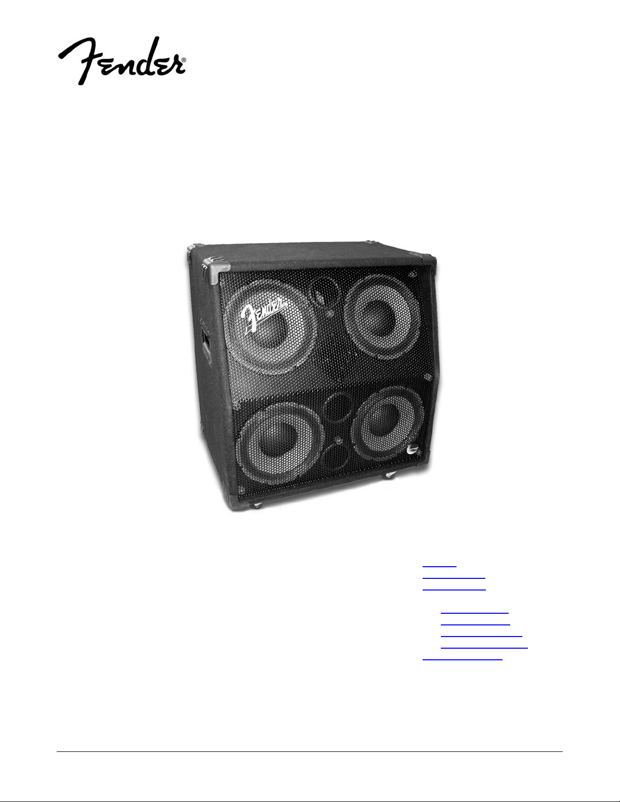
BASSMAN® 410 PRO SL LOUDSPEAKER
(This is the model name for warranty claims)
SERVICE MANUAL
1
p/n 2217000000 (120V)
CONTENTS:
Notices .............................. 2
Specifications.................... 3
Service Notes.................... 4
Parts Lists:
PCB Assembly............ 5
Input Assembly........... 5
Cabinet Assembly ...... 5
End Item Assembly .... 5
Service Diagrams.............. 6
Fender® Musical Instruments Corp. 8860 East Chaparral Road Suite 100 Scottsdale, AZ 85250
Page 2

BASSMAN® 410 PRO SL LOUDSPEAKER
(This is the model name for warranty claims)
June, 2002
IMPORTANT NOTICE
2
Copyright © 2002 FMIC. All rights reserved. All
•
information contained herein is CONFIDENTIAL
and PROPRIETARY and is the property of
Fender® Musical Instruments Corporation. It is
not to be sold or assigned to another party and is
disclosed solely for use by Fender Authorized
Service Centers for purposes of product service
and maintenance. All information is not to be disclosed to others without the expressed permission
of Fender® Musical Instruments Corporation. All
PARTS LIST CODES
The description codes used in the itemized Parts Lists are defined below:
CAPACITOR CODES
CAP AE = Aluminum Electrolytic
CAP CA = Ceramic Axial
CAP CD = Ceramic Disk
CAP MPF = Metalized Polyester Film
CAP MY = Mylar
CAP PFF = Polyester Film/Foil
RESISTOR CODES
RES CC = Carbon Comp
RES CF = Carbon Film
RES FP = Flame Proof
RES MF = Metal Film
RES WW = Wire Wound
specifications are subject to change without notice. This information and any copies produced
electronically or otherwise must be surrendered
upon demand of Fender Musical Instruments Corporation.
Parts marked with two asterisks (**) indicate the
•
required use of that specific part. This is necessary for RELIABILITY and SAFETY requirements.
DO NOT USE A SUBSTITUTE!
HARDWARE CODES
BLX = Black Oxide
CR = Chrome Plated
HWH = Hex Washer Head
M = Machine Screw
NI = Nickel Plated
OHP = Oval Head Phillips
PB = Particle Board
PHP = Pan Head Phillips
PHPS = Pan Head Phillips Sems
SMA = Sheet Metal "A" Point
SMB = Sheet Metal "B" Point
SS = Stainless Steel
TF = Thread Forming
ZI = Zinc Plated
Page 3

BASSMAN® 410 PRO SL LOUDSPEAKER
(This is the model name for warranty claims)
SPECIFICATIONS
Model Name: Bassman 410 Pro SL
Release Number: PR 523 (Not a model number)
3
Part Number:
Impedance: 8 ohms
Sensitivity: 94 dB, 1 Watt – 1 meter
Power Handling: 300 Watts, Continuous
Drivers: Four 10” (25.4 cm) Fender® Special Design cast frame Woofers,
Connections: Dual, parallel wired, 1/4” (6.35 mm) high current Input Jacks and Binding Posts
Cabinet:
Enclosure Volume: VB = 4.4 ft3 (125 l)
2217000000
600 Watts, Program
2” (5.1 cm) Voice Coil, 44 oz. (1.25 kg) Magnet (p/n 057982)
One Horn Tweeter
1” (2.5 cm) Voice Coil, 8 oz. (0.23 kg) Magnet
3/4” (1.9 cm) 7-ply Birch-Maple Plywood
Dimensions Height: 25 1/2 in (64.8 cm)
Width: 25 1/2 in (64.8 cm)
Depth: 18 1/2 in (47.0 cm)
Weight: 78 lbs (35.5 kg)
Product specifications are subject to change without notice.
Page 4

BASSMAN® 410 PRO SL LOUDSPEAKER
(This is the model name for warranty claims)
SERVICE NOTES
4
INPUT PANEL removal is required for fuse
replacement and is accomplished by following
these steps:
Remove the 4 screws from the input panel cor-
1.
ners.
2. Pull the panel out, then up.
PCB EXCHANGE POLICY
Parts marked with a single asterisk (*) in the Part
Lists are not field replaceable. If a failure due to
one of these components is detected, please con-
Use a small flathead screwdriver to remove the
3.
blown lamp, which is visible through a cutout in
the circuit board.
Remove the spare lamp stowed on the side of
4.
the circuit board and install it where the blown
lamp was removed.
Install the input jack plate in the reverse of re-
5.
moval.
tact the Fender® dealer Customer Service
Department to order the complete PCB Assembly.
Page 5

BASSMAN® 410 PRO SL LOUDSPEAKER
(This is the model name for warranty claims)
5
PARTS LIST:
QTY. PART # DESCRIPTION REFERENCE DESIGNATION
1 0057979000
1 0057978000 PCB FABRICATION BASSMAN 410 PRO
2 0051861000 CAP MPF RDL 3.3 UF 250V 10%
4 0012555000 EYELET-ROLLED FLANGE G.S. 3-4
1 0051858000 INDUCTOR AIR CORE .18 MH
2 0029175000 JACK PHONE ¼” HI CURRENT PC
4 0053475000
2 0051857000
1 0059613000 WIRE SET PCB BASSMAN 410 PRO
**PCB ASSEMBLY BASSMAN 410 PRO
**LAMP CLIP
**LAMP TYPE 561
PARTS LIST:
QTY. PART # DESCRIPTION REFERENCE DESIGNATION
1 0057983000 INPUT ASSY BASSMAN 410 PRO
1 0049348000 CONTROL L PAD 8 OHM 50W
1 0059612000 FIVE WAY BINDING POST
1 0029531000 KNOB KNURL BLK SUNN 1272/1275
2 0016352000 NUT HEX 3/8-32 X 3/32 TK NI
1 0057976000 PLATE INPUT BASSMAN 410 PRO
2 0031153000 WSHR FLAT 3/8 X .614 NI
2 0016436000 WSHR LCK INTL 3/8 X .687 X .035 NI
PARTS LIST:
QTY. PART # DESCRIPTION REFERENCE DESIGNATION
8 0057945000 CABINET CORNER, PLASTIC
2.745 0040046000 CARPET BLACK SY
2 0057946000 HANDLE, SPRING LOADED
4 0056482000 MOUNTING PLATE EL COM
32 0021972000 NUT T 10-32 X ¾ STR 3 PRNG BLX
32 0016627000 SCRW SMA 8 X ¾ OHP BLX
16 0027199000 SCRW SMAB 10 X ¾ PHP NI
20 0033380000 SCRW SMAB 8 X 1 THP BLX
PCB ASSEMBLY
INPUT ASSEMBLY
CABINET ASSEMBLY
PARTS LIST:
QTY. PART # DESCRIPTION REFERENCE DESIGNATION
1 0057933000 CABINET ASSEMBLY BASSMAN 410 PRO SL
4 0056483000 CASTER SWIVEL EL COM 2-12 CABS
1 0055831000 GASKET, HORN BASSMAN AMPS
1 0057931000 GRILLE BASSMAN 410 PRO SL
1 0048847000 HORN FOSTER 8 OHM
1 0054212000 INPUT MOUNTING PLATE SUNN 410H
1 0055731000 LOGO BADGE BASSMAN AMPS
1 0057981000 MANUAL OWNERS BASSMAN 410 PRO
1 0047600000 NAMEPLATE FENDER BLACK
4 0050311000 NUT 2-56 NYLON INSERT 2CNME-Z
4 0050312000 SCRW 2-56 X 3/8 FHP NI
8 0030858000 SCRW 8 X 5/8 PHP NI
32 0057975000 SCRW M10-32 X 1-1/4 FLHP STL BLX
4 0026553000 SCRW M8-32 X 3/8 PHP BLX
8 0036112000 SCRW SMAB 6 X 1-1/4 OHP BLX W/WS
4 0033380000 SCRW SMAB 8 X 1 THP BLX
4 0057982000 SPEAKER 10 INCH 8 OHM CAST FRAME
* Non-serviceable part. Replace complete parent assembly. See PCB EXCHANGE POLICY on page 4.
Unique Fender® part. Order directly from the Fender® dealer Customer Service Department.
** Safety Requirement part. Replacement must match Safety Agency…–Value, if specified –Type, if specified –Approval Mark(s) if on part.
** Both a unique Fender® part and a Safety Requirement part as defined above.
END ITEM ASSEMBLY
Page 6

BASSMAN® 410 PRO SL LOUDSPEAKER
(This is the model name for warranty claims)
6
PARTS LIST:
QTY. PART # DESCRIPTION REFERENCE DESIGNATION
3 0057971000 SPEAKER PORT 3.00 DIA
8 0050317000 STANDOFF RUBBER .75 DIA X .77
1 0053489000
**WIRE SET FINAL SUNN 410H
END ITEM ASSEMBLY
Schematics and Drawings
Service Diagram (Schematic) ............Bassman 410 Pro SL
End Item Assembly ............Bassman 410 Pro SL
* Non-serviceable part. Replace complete parent assembly. See PCB EXCHANGE POLICY on page 4.
Unique Fender® part. Order directly from the Fender® dealer Customer Service Department.
** Safety Requirement part. Replacement must match Safety Agency…–Value, if specified –Type, if specified –Approval Mark(s) if on part.
** Both a unique Fender® part and a Safety Requirement part as defined above.
Page 7

Page 8

D
 Loading...