

Page 1
SSAANN UUNNIITT OOPPEERRAATTIIOONN M
OOOO
rrrr
iiii
gggg
iiii
nnnn
aaaa
OOOO
rrrr
iiii
gggg
iiii
nnnn
aaaa
UUUU
pppp
UUUU
pppp
EELLEECCTTRRIICC SSEERRVVOO NNUUTTRRUUNNNNEERR
AAFFCC11550000 MMUULLTTII SSYYSSTTEEMM
MAANNUUAALL
SSttaanndd--AAlloonnee && MMUULLTTII TTyyppee
llll
MMMM
oooo
dddd
eeee
llll
ssss
----
SSSS
AAAA
NNNN
2222
----
1111
2222
MMMM
////
SSSS
AAAA
NNNN
2222
----
2222
4444
MMMM
////
SSSS
AAAA
NNNN
2222
----
4444
0000
MMMM
////
SSSS
AAAA
NNNN
llll
MMMM
oooo
dddd
eeee
llll
ssss
----
SSSS
AAAA
NNNN
2222
----
1111
2222
MMMM
////
SSSS
AAAA
NNNN
2222
----
2222
4444
MMMM
////
SSSS
AAAA
NNNN
2222
----
4444
0000
MMMM
////
dddd
aaaa
tttt
eeee
dddd
MMMM
oooo
dddd
eeee
llll
ssss
----
SSSS
AAAA
NNNN
3333
----
2222
4444
MMMM
////
SSSS
AAAA
NNNN
3333
----
4444
0000
MMMM
////
SSSS
AAAA
NNNN
3333
----
dddd
aaaa
tttt
eeee
dddd
MMMM
oooo
dddd
eeee
llll
ssss
----
SSSS
AAAA
NNNN
3333
----
2222
4444
MMMM
////
SSSS
AAAA
NNNN
3333
----
4444
0000
MMMM
////
SSSS
SSSS
AAAA
NNNN
3333
----
2222
4444
HHHH
MMMM
////
SSSS
AAAA
NNNN
3333
----
6666
SSSS
AAAA
NNNN
3333
----
2222
4444
HHHH
MMMM
////
SSSS
AAAA
Sixth Edition October 2009
0000
NNNN
3333
----
6666
0000
1111
AAAA
NNNN
3333
----
1111
HHHH
MMMM
HHHH
MMMM
2222
SSSS
AAAA
NNNN
2222
2222
0000
TTTT
MMMM
////
2222
0000
TTTT
MMMM
////
----
8888
0000
----
8888
0000
SSSS
SSSS
AFC1500E-HS-6
MMMM
////
SSSS
AAAA
NNNN
2222
MMMM
////
AAAA
NNNN
3333
AAAA
NNNN
3333
----
SSSS
AAAA
NNNN
2222
----
----
1111
2222
0000
WWWW
----
1111
2222
0000
WWWW
MMMM
MMMM
1111
2222
0000
MMMM
1111
2222
0000
MMMM
Page 2

WARNING
All applicable national and local codes must be followed when installing and operating the
equipment detailed in this manual.
FAILURE TO ABIDE BY THESE CODES AND THE SPECIFICATIONS DESCRIBED IN THIS
MANUAL CAN RESULT IN SERIOUS INJURY TO PERSONNEL AND/OR DAMAGE TO THE
EQUIPMENT!
Any questions regarding the contents of this document or any related matter should be directed
to FEC INC. at (586) 781-2100, faxed to (586) 781-0044 or emailed to support@fec-usa.com.
The information set forth in the following document is the property of FEC INC.
This document shall not be released to or copied for any person and/or organization
With out the expressed prior consent of FEC INC.
Unauthorized reproduction or distribution of this manual is strictly prohibited.
Please contact FEC INC. if you require additional copies.
Page 3
= SAN Unit Hardware Operation
FUSION
FUSIONFUSION
FUSION
= DC Hand Tool
Revision History
Revision
date
1998/01/12 First Edition Original Manual
Manual No. Content of revision
2002/01/12 Second Edition
2003/01/03 Second Edition Corrections to First Update (internally referred to as 3rd edition)
2007/01/30 AFC1500E-HS-4
2008/02/19 AFC1500E-HS-5
2009/10/30 AFC1500E-HS-6
DSP1500
DSP1500 = Servo Press
DSP1500DSP1500
DSP1500
DSP1500 = Servo Press
DSP1500DSP1500
AFC1500
AFC1500 = Nutrunner
AFC1500AFC1500
AFC1500
AFC1500 = Nutrunner
AFC1500AFC1500
FUSION
FUSION = DC Hand Tool
FUSIONFUSION
EEEE = English Version
SSSS = Spanish Version
****Japanese Version furnished by DDK
uses DDK numbering convention.
First update
First major revision.
Combination of SAN2 and SAN3 Servo Drive into a single Manual.
Combination of Stand-Alone and Multi Unit operation into a single Manual.
Updated for SAN3-24HM & SAN3-60HM models (High Speed motors)
Updated power consumption specifications
Updated for SAN3-DP1 &DP2 (including RTC setup for this)
Updated for special Dual Transducer setup
Various text, notes & edits
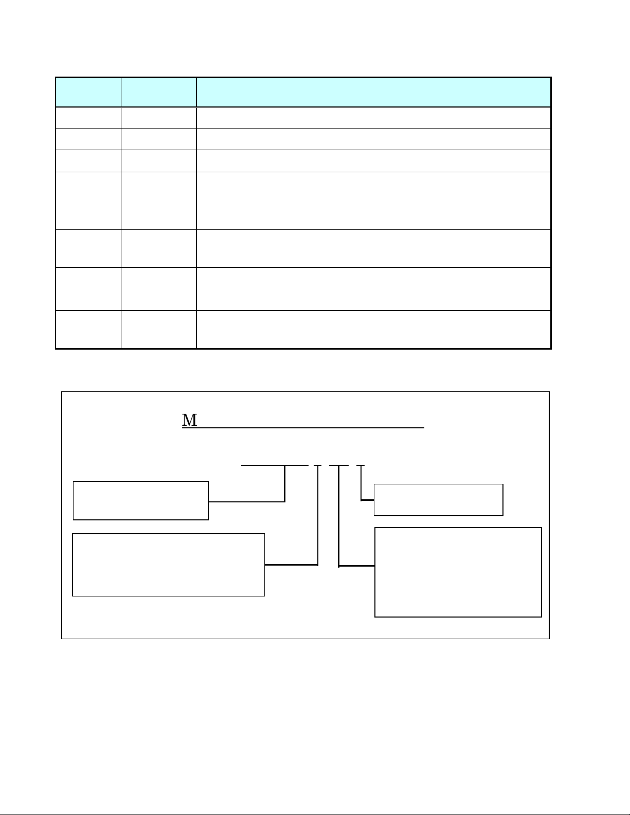
Manual Numbering Convention
AFC1500E-HS-6
Version Number
(Major Revision Level)
HS
HS
HSHS
Manual
HM
HM = Multi / Main Unit Hardware
HMHM
Operation Manual
HM
HM----ENET
ENET = Ethernet Manual for
HMHM
ENETENET
Multi / Main Unit
SW
SW = Software Manual
SWSW
Page 4
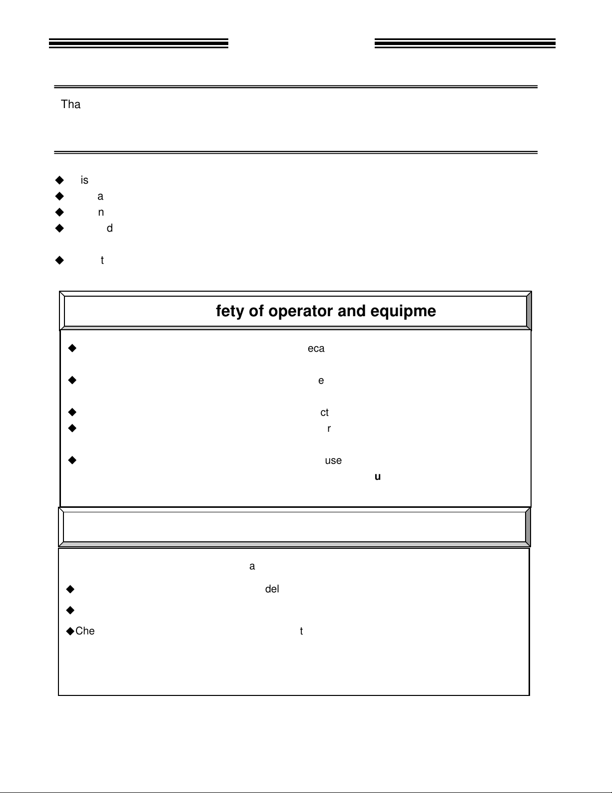
Introduction
Thank you for purchasing our Electric Servo Nutrunner - AFC1500 System.
This instruction manual describes the procedures for installation, wiring, and handling, and actions
to be taken in case of any failure.
◆
This instruction manual shall be delivered to the end user who operates the equipment.
◆
Read all instructions before use, and always keep this instruction manual with the equipment.
◆
Items not described in this instruction manual shall be considered “unavailable”.
◆
The product specification and appearance described in this instruction manual is subject to change
without notice.
◆
All rights reserved. Any disclosure, copying, distribution, or use of the information contained herein for
other than its intended purpose, is strictly prohibited.
◆
It is important for you to read all “Safety Precautions” before using the equipment, and
understand and observe all instructions and recommendations included in this manual.
◆
Read all instructions and recommendations included in this manual, understand the functions
and performance of this nutrunner, and correctly use this machine.
◆
Wirings and parameter settings shall only be conducted by a qualified professional.
◆
Never conduct a withstand voltage test or insulation resistance test on this equipment.
◆
Indicate the following on all instruction manuals that use this equipment.
”This equipment is capable of high voltages hazardous to human life.”
Please confirm the followings when unpacking this equipment.
◆
Ensure that you received the correct model, as ordered.
◆
Ensure that there are no missing parts.
◆
Check for any damage caused during transportation.
For the safety of operator and equipment
Points to check when unpacking
Page 5

Introduction
Warranty Period
FEC Inc. warrants that the equipment manufactured by it and delivered hereunder will be free of
defects in material and workmanship for a period of twelve (12) months from the date of placing the
equipment in operation, or eighteen (18) months from the date of shipment, or 500,000 machine
cycles - whichever shall first occur.
Provision of warranty
Should any failure to conform to this warranty be reported in writing to the company within said
period, the company shall at its option, correct such nonconformity by suitable repair to such
equipment or furnish a replacement part from FEC or an FEC approved facility, provided the
purchaser has stored, installed, maintained and operated such equipment in accordance with good
industry practices and has complied with specific requirements & recommendations of the
company. Accessories or equipment furnished by the company shall not be liable for any repairs,
replacements or adjustments to the equipment or any costs of labor performed by the purchaser or
others without the company's prior written approval.
The effects of corrosion, erosion and normal wear and tear are specifically excluded from the
company's warranty. Performance warranties are limited to those specifically stated within the
company's proposal. Unless responsibility for meeting such performance warranties are limited to
specified shop or field tests, the company's obligation shall be to correct in the manner and for a
period of time provided above.
THE COMPANY MAKES NO OTHER WARRANTY OR REPRESENTATION OF ANY KIND
WHATSOEVER, EXPRESSED OR IMPLIED, EXCEPT THAT OF TITLE, AND ALL IMPLIED
WARRANTIES, INCLUDING ANY WARRANTY OF MERCHANTABILITY AND FITNESS FOR A
PARTICULAR PURPOSE, ARE HEREBY DISCLAIMED.
Correction by the company of nonconformity's, whether patent or latent in the manner and for the
period of time provided above, shall constitute fulfillment of all liabilities of the company for such
nonconformity's, whether based on contract, warranty negligence, indemnity, strict liability or
otherwise with respect to, or arising out of such equipment.
The following are defined as non-warranty situations that are outside the scope of warranty
provided;
• Product is out of the warranty period as determined by FEC serial number tracking.
• Any cause external to the equipment, including but not limited to any act of God, lighting or power
surges, abuse, negligence, accident or failure to maintain the proper operating environment.
• Use of equipment or adjustments or devices not approved by the manufacturer and FEC.
• Cosmetic damage to unit or any of the parts
• Consumable parts - for example; sockets, rest/wear pads, bushings, etc.
• Physical damage (example - damage caused by dropping, cut cables, etc.)
• Field Service required on a Warranty Part - FEC warranty covers the parts and labor only onsite
at FEC.
Extended warranties are available as an addition to the standard warranty period outlined above - for all
FEC Inc. systems. Please contact FEC if you are interested in an extended warranty.
Warranty
Page 6
ead all instructions before operating the
manual carefully
Safety precautions in this manual
To prevent danger to the user and other persons as well as property damage
with the symbols
This instruction manual uses the
caused when the instruction is not observed.
nstructions that are marked with
marked with the above symbols
marked with
the following additional
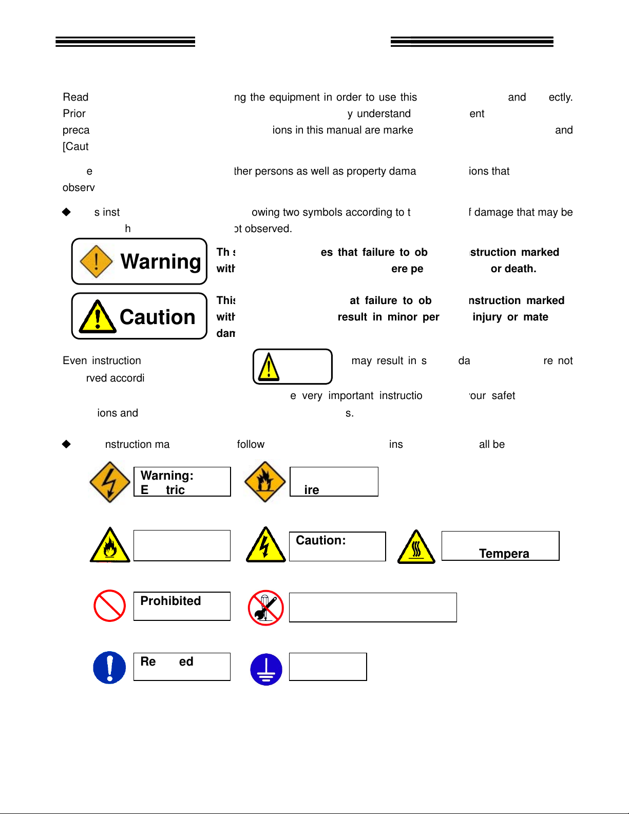
This symbol indicates that failure to observe instr
with this symbol
This symbol indicates that failure to observe instruction marked
with this symbol
damage.
Electric shock
Fire
Safety Precautions
equipment safely and
the equipments functions, safety
are marked with two symbols
nstruction
two symbols according to the degree of damage that may be
may result in severe damage
. For your safety, f
that shall be observed.
may result in severe personal injury or death.
personal injury or
F
ire
Electric shock
Caution:
High Temperature
R
Prior to use, read this instruction
precautions and instructions.
[Caution].
observed are marked
◆
Even i
observed according to conditions.
Warning
Caution
equipment in order to use this
below.
following
and fully understand
may result in minor
Caution
, i
correctly.
[Warning] and
s that must be fully
uction marked
material
if they are not
Contents
instructions and especially those
◆
This instruction manual uses
Warning:
Caution:
Prohibited
Required
are very important instructions
these symbols.
symbols for instructions
Warning:
Caution:
Do not disassemble
Ground
ollow all
Page 7
and gear case
output spindle may rotate and cause injury.
Do not repair, disassemble, or modify the equipment
this instruction may cause
Never operate the equipme
Failure to observe
Keep fingers away from the
the equipment is turned OF
operation and maintenance work shall be conducted by a
this instruction may cause
Turn OFF the power when conducting wiring operation
this instruction may cause
damage the cables, apply excess
Never use damaged cables.
this instruction may cause
3 grounding of FG terminals.
this instruction may cause
abnormal odor, noise, or operation error
source.
device
this instruction may cause
emergency stop circuit
Failure to observe
Keep away from the equipment
fter
this instruction may cause
Safety Precautions
individual components of the system.
injury, electric shock, fire, and malfunction.
atmosphere
for a while after
electric shock
professional.
the cables.
stop operation
injury and fire.
peration
, and
suddenly restart.
Warning
Do not remove the motors
The tool
Failure to observe
or flammable gases.
Wiring
Failure to observe
Failure to observe
Never
Conduct type Failure to observe
Failure to observe
In case of an
and turn OFF the power
Install a Power shutdown
Failure to observe
Install an
promptly.
measures are conducted a
Failure to observe
s of tools while power is applied..
nt where it is exposed to water, near a corrosive
this instruction may cause fire.
connectors while the equipment is turned ON and
F. Failure to observe this instruction may cause
qualified
electric shock and injury.
and maintenance.
electric shock and injury.
stress to cables, or squeeze
electric shock and fire.
electric shock.
occurrence,
Failure to observe this instruction may cause
in order to ensure the safety of equipment.
injury.
on the outside of equipment in order to stop o
this instruction may cause injury.
during recovery from a temporary blackout
restarting the equipment. The equipment may
injury.
.
.
immediately
ensure safety
Page 8
Transport the equipment properly according to its weight.
this instruction may cause
The conditions when transporting the equipment by ship is as below.
-
0% RH or lower
Rust prevention measure: Apply grease or oil on tools.
this instruction may cause
Do not hold cables and output spindles when t
this instruction may cause
indictor on the
The indicator may come off and drop from the front panel.
this instruction may cause
The equipment shall be stored under the following conditions.
-
Ambient humidity: 90% RH or lower
Indoors (Avoid direct sunlight)
corrosive gases or flammable gases
No oil mist, dust, water, salt, iron powder
Avoid direct vibration or shocks
this instruction may cause
Safety Precautions
Transportation / Storage
Caution
Failure to observe
injury and malfunction.
◆
Ambient temperature:
◆
Ambient humidity: 5
◆
Package: Tight seal
◆
Failure to observe
Failure to observe
Do not hold the
5°C~+55°C (Avoid freezing)
(Avoid moisture)
earth leakage and malfunction.
ransporting the tools.
injury and malfunction.
front panel when transporting the AXIS Unit.
Failure to observe
injury and malfunction.
◆
Ambient temperature:
◆
◆
Atmosphere:
◆
Failure to observe
No
5°C~+55°C (Avoid freezing)
(Avoid moisture)
earth leakage and malfunction.
Page 9
where they can bear the maximum torque
this instruction may cause
inside the control panel using the specified screws.
this instruction may cause
Use the specified tool for the AXIS
this instruction may cause
Unit shall
this instruction may cause
ventilation hole
from entering
this instruction may cause
The power source shall be provided with safety measures
Failure to observe
(SAN)
this instruction may cause
get on the top of equipment or do not place heavy
this instruction may cause
equipment
this instruction may cause
Conduct wirings properly and firmly.
this instruction may cause
Operate the equipment within the specified power supply voltage
this instruction may cause
When operating the equipment in the following conditions,
electrical
where the equipment is subjected to
power wire.
this instruction may cause
Safety Precautions
Installation / Wiring
during operation.
and
fire and malfunction.
on the top of equipment.
, and malfunction.
hock, fire, and malfunction.
measures
magnetic field
injury, false operation, and malfunction.
Caution
Install all tools firmly
Failure to observe
Install the AXIS Unit firmly
Failure to observe
Failure to observe
The AXIS (SAN)
Failure to observe
Do not block the
Avoid any foreign body
Failure to observe
Failure to observe
circuit protectors.
Do not use tools or AXIS
Do not
Failure to observe
Do not subject the
Failure to observe
Failure to observe
Failure to observe
to shield the equipment.
◆
Location where
◆
Location
◆
Location near a high
Failure to observe
injury and malfunction.
malfunction.
(SAN) Unit.
fire and malfunction.
maintain the specified distance from other devices.
fire and malfunction.
of the AXIS (SAN) Unit.
inside the equipment.
fire and malfunction.
this instruction may cause
Units that are damaged or missing parts.
fire, injury, and malfunction.
injury, and malfunction.
to excess shock and impact.
malfunction.
injury, false operation
injury, electric s
noise is generated
a strong electric field or
such as breakers
objects
take sufficient
.
Page 10
Never operate the equipment with wet hands.
this instruction may cause electric shock.
Keep fingers away from the
is turned ON or for a while after the equipment is turned OFF. These parts may become very
this instruction may cause burns.
Use the equipment under the following conditions.
0°C
Ambient humidity: 90% RH or lower
Indoors (Avoid direct sunlight)
corrosive gases or flammable gases
No oil mist, dust, water, salt, iron powder
Avoid direct vibration or s
this instruction may cause
ll parameters before operation
movement of the equipment.
this instruction may cause injury,
adjustments or setting changes that may cause instability of
this instruction may cause injury,
The equipment may restart suddenly
Always ensure that the start signal is OFF before resetting the equipment.
instruction
Do not turn ON and OFF the equipment repeatedly.
instruction
equipment at torque higher than
Failure to observe this instruction may shorten
due to the high temperature caused by overload.
mality occurs,
and restarting the equipment.
Failure to observe this instruction may cause injury.
Safety Precautions
Operation
/ Adjustment
tool motors while the equipment
in order to prevent unexpected
and malfunction.
and malfunction.
is reset with the start signal ON.
or cause malfunction
remove the cause and ensure safety before resetting
Caution
Failure to observe
AXIS (SAN) Unit radiating fin and
hot. Failure to observe
◆
Ambient temperature:
◆
◆
Atmosphere:
◆
Failure to observe
Confirm and adjust a
Failure to observe
Never conduct extreme
Failure to observe
Failure to observe this
Failure to observe this
Do not use the
In case any abnor
No
~
+45°C (Avoid freezing)
(Avoid moisture)
hocks
earth leakage and malfunction.
when the equipment
may cause injury.
may cause malfunction.
the maximum torque.
equipment life
false operation
false operation
operation.
Page 11

Table of Contents
Chapter 1: Outline
1-1
Chapter 2: Specifications
2-1
Chapter 3: System Description
3-1
Chapter 4: System Setup and Wiring
4-1
1.1 About This operations manual 1-2
1.2 Features 1-3
1.3 Functions 1-5
1.4 System requirements 1-7
2.1 Main Specifications 2-2
2.2 Duty Cycle Calculation 2-3
2.3 SAN Unit Specifications 2-4
2.4 Capability. 2-5
2.4.1 Nutrunner Tool Specification Table 2-6
2.4.2 Nutrunner Decimal Point Display Table 2-7
3.1 System Block Diagram 3-2
3.1.1 Multi System Block Diagram Description 3-2
3.1.2 Stand Alone System Block Diagram Description 3-4
3.2 AFC1500 SAN UNIT Front panel 3-6
3.2.1 AFC1500 Front Panel Switches and Connectors 3-6
3.2.2 AFC1500 Status LED and Bypass Switch Description 3-7
3.3 AFC1500 Keyboard-Display description - SAN DP1/DP3 3-8
3.4 AFC1500 Keyboard-Display description - SAN DP2/DP4 3-9
3.4.1 SAN-DP2/DP4, SAN3-DP1/DP2 Serial Pin out 3-9
3.4.2 SAN DP2/DP4, SAN3-DP1/DP2 Communication Protocol 3-10
3.4.3 SAN DP2/DP4, SAN3-DP1/DP2 Communication Format 3-10
3.4.4 SAN DP2/DP4, SAN3-DP1/DP2 Communication Format Description 3-11
3.4.5 Cable Connection to SAN DP2/DP4, SAN3-DP1/DP2 3-12
3.5 Nutrunner (Tool) Unit 3-13
Page
4.1 Design and Build Procedure 4-2
4.2 Component Dimensions 4-3
4.2.1 SAN Controller Unit Dimensions 4-3
4.3 Unit Arrangement 4-4
4.4 Nutrunner (Standard Tool) Dimensions 4-5
4.4.1 Straight Tool 4-5
4.4.2 Offset Tool 4-7
4.4.3 High Speed Tool – SA Version 4-8
4.4.4 High Speed Tool – SS Version 4-9
4.4.5 Mounting Plate Design Requirements 4-10
4.4.6 Locating Procedure for Fixtured Multi-Spindled Powerhead 4-10
4.5 Wiring Diagrams 4-12
4.6 Power Requirements and Connections 4-13
4.6.1 SAN 4-13
4.6.2. Calculating Circuit Protection 4-14
4.7 Wiring PLC I/O 4-15
4.7.1 Explanation of SAN Unit I/O 4-16
4.7.2 Work / Parameter Select Table 4-18
4.7.3 Bank Select Table 4-19
4.7.4 Bank Output Servo Error Table 4-21
Page 12

4.7.5 PLC Wiring Sample 4-22
Chapter 5: Power Up and
Initial Checks
5-1
Chapter 6: Fastening Instructions
6-1
Chapter 7: System Operations
7-1
4.7.6 Synchronized Fastening Operation(Without MULTI UNIT) 4-23
4.7.7 Signal Timing Chart 4-24
4.8 RS-485 Data communication ports. 4-26
4.9 MON. Connector -Torque/Angle/Current/Speed OUTPUT 4-27
4.9.1 Monitoring connector Output Circuit. 4-28
4.10 SAN Unit DIP Switch setting. 4-29
4.10.1 SAN Unit DIP switch positions 1 ~ 3 4-29
4.10.2 SAN Unit DIP switch positions 4 ~ 8 4-30
4.11 Tool Connection (cabling) 4-31
4.11.1 Cable Installation Guidelines 4-32
4.11.2 Considerations for Cable Trolleys 4-33
4.11.3 Considerations for Flexible Cable Tracks 4-33
4.11.4 Considerations for Cable Trays and Ladders 4-33
4.11.5 Preamplifier connector. 4-34
4.11.6 Motor connector 4-34
4.11.7 Resolver connector 4-35
4.12 Firmware Flash Connector (CN8). 4-36
5.1 Before Powering On 5-2
5.2 Initial Data Setting 5-3
6.1 Fastening Control 6-2
6.1.1 Torque Control Method 6-2
6.1.2 Angle Control Method 6-6
6.2 Monitoring Functions 6-12
6.2.1 Peak Torque Monitoring 6-12
6.2.2 Final Torque Monitoring 6-14
6.2.3 Angle Monitoring 6-16
6.2.4 Point-to-Point Torque Rate Monitoring 6-18
6.2.5 Time Monitoring 6-20
6.3 Speed Functions 6-21
6.4 Reverse Functions 6-23
6.5 Torque Recovery 6-24
6.6 Added Functions 6-25
6.6.1 Current Monitor / Control 6-25
6.6.2 Offset Check / Offset Correct 6-26
6.6.3 Angle Correction 6-26
6.6.4 One Pulse Reverse Function 6-26
6.6.5 Quarter Torque Recovery 6-27
6.6.6 Reduced Fastening Reaction 6-27
6.6.7 Varispeed 6-27
6.6.8 Rundown Revolution Limits 6-28
6.6.9 Torque Inhibit Function 6-28
6.6.10 Fastening End by Self Check Off Signal 6-28
7.1 AFC1500 Detachable Display and Programming unit operation. 7-2
7.1.1 Manual Fastening controls for Display Programming (DP) Unit 7-2
7.1.2 Fastening Preset Results Display 7-3
7.1.3 Fastening Presetting / Result Display Controls 7-3
7.2 Run State Modes. 7-4
7.2.1 Display indication modes. 7-4
Page 13

7.2.2 Real-time display indication mode. 7-5
Chapter 8:
Maintenance and Inspection
8-1
Chapter 9: Troubleshooting
9-1
7.2.3 Fastening results display mode. 7-6
7.2.4 Parameter display mode 7-7
7.2.5 Parameter Data List 7-9
7.2.6 Status Display 7-22
7.3 Download / Setup Mode Operation. 7-23
7.3.1 Download Mode selection 7-23
7.3.2 Setup Mode selection 7-24
7.3.3 Parameter # Selection. 7-25
7.3.4 Data # selection 7-26
7.3.5 Data Edit Mode Operation 7-27
7.3.6 Parameter Copy 7-28
7.3.7 I/O Enable (Stand Alone or Multi Configuration) 7-29
7.3.8 Dual Transducer Set-up 7-30
8.1 Inspection Items 8-2
8.1.1 Nutrunner (Tool) 8-2
8.1.2 Spindle Assembly 8-2
8.1.3 Homerun cables 8-2
8.1.4 SAN unit 8-3
8.1.5 Air Handling Units (Air Conditioner, Heat Exchanger, etc.) 8-3
8.2 Basic operational tests 8-4
8.2.1 Torque transducer. 8-4
8.2.2 Resolver. 8-4
8.2.3 Motor. 8-4
8.2.4 Transmission Disassembly and Inspection 8-6
8.3 Replacements 8-9
8.3.1 SAN Unit Replacement 8-9
8.3.2 Replace Nutrunner (tool) 8-10
8.3.3 Replace Homerun cables 8-10
9.1 Abnormal Conditions. 9-2
9.2 Torque Transducer Origin Error, Cal Check Error. 9-3
9.2.1 Code 1-0 Torque transducer / Zero Voltage error. 9-3
9.2.2 Code 1-1 Torque transducer / Cal Voltage error. 9-3
9.2.3 Code 1-2 Torque transducer / Zero check error. 9-3
9.2.4 Code 1-3 Torque transducer / Cal self-check error. 9-4
9.2.5 Code 1-4 Torque transducer / Started on Zero condition error. 9-4
9.2.6 Code 1-5 Torque transducer / Started on Cal condition error 9-4
9.2.7 Code 1-6 Torque transducer / Zero Level Self Check Error 9-4
9.3 Torque Over Abnormals 9-5
9.3.1 Code 2-0 Torque Over Abnormal / Offset Torque 9-5
9.3.2 Code 2-1 Torque Over Abnormal / Torque Inhibit High Limit 9-5
9.4 Tool EEPROM Errors 9-6
9.4.1 Code 3-0 Preamplifier / Tool ID Checksum error 9-6
9.4.2 Code 3-1 Preamplifier / Tool type error 9-6
9.4.3 Code 3-2 Preamplifier / Started without tool connected 9-6
9.4.4 Code 3-3 Preamplifier / Tool is not connected 9-6
9.5 System Memory Errors 9-7
9.5.1 Code 4-0 system memory error / Flash ROM write error 9-7
9.5.2 Code 4-1 system memory error / Flash ROM read error 9-7
9.5.3 Code 4-2 system memory error / Servo Amp Flash ROM error 9-7
9.6 Servo Amplifier Response / Resolver 9-8
Page 14

9.6.1 Code 5-0 Servo Amplifier reply error / No reply from Resolver 9-8
Appendix A
RMA Supplement.
A-2
Data Parameter
Setting Blank Form.
A-3
Tool List (Straight, Offset, U
-
Tools)
A-4
Tool List (Right Angle tools)
A-5
AFC1500 SAN2 with MULTI UNIT
- Cable Map.
A-6
AFC1500 SAN3 with MULTI2 UNIT
- Cable Map.
A-7
AFC1500 SAN2 Axis Unit Connection Reference.
A-8
AFC1500
SAN3 Axis Unit Connection Reference.
A-9
AFC1500 Transformer.
A-10
AFC1500 SAN / Multi Power Cable.
A-11
AFC1500 SAN3
-
120WM Power Cable.(RM5)
A-12
AFC1500 System Motor / Resolver Cables.(RM1,2,3,4)
A-13
AFC1500 System Pre
-
Amp Cable.(RM1,2,3,4,5)
A-14
AFC1500 System Motor Cable.(RM5)
A-15
AFC1500 System Resolver Cable.(RM5)
A-16
AFC1500 System Motor / Resolver Ext. Cables.(RM1,2,3,4)
A-17
AFC1500 System Pre
-
Amp Ext. Cable.(RM1,2,3,4,5)
A-18
AFC1500 System Motor Ext. Cable.(RM5)
A-19
AFC1500 System
Comm. Cable (RS232/422 Converter).
A-20
AFC1500 Comm. Cable (Axis to Axis unit).
A-21
AFC1500 MULTI Unit Null Modem Cable
A-22
AFC1500 SAN2 Unit I/O cable
A-23
AFC1500 SAN3 Unit I/O cable
A-24
AFC1500 SAN2 ~ SAN3 Adapter Cable
A-25
AFC1500 SAN3 ~
SAN2 Adapter Cable
A-26
AFC1500 System Motor/Resolver/Preamp Cable (RH1,3)
A-27
AFC1500 System Motor/Resolver/Preamp Ext. Cable (RH1,3)
A-28
9.7 Servo Type Error 9-9
9.7.1 Code 6-0 Servo Type error / Servo Type mismatch 9-9
9.8 Internal Error 9-10
9.8.1 Code 7-0 Internal error / Internal power supply abnormal 9-10
9.8.2 Code 7-1 Internal error / Signal Timing Error 9-10
9.9 Servo Amplifier Error 9-11
9.9.1 Code 8-1 Servo Amplifier error / Servo is over heated 9-11
9.9.2 Code 8-4 Servo Amplifier error / Over current 9-11
9.9.3 Code 8-5 Servo Amplifier error /Internal power supply. 9-11
9.9.4 Code 8-6 Servo Amplifier error / Input Voltage abnormal 9-12
9.9.5 Code 8-9 Servo Amplifier error / Over speed. 9-12
9.9.6 Code 8-10 Servo Amplifier error / over load ( I square T) 9-12
9.9.7 Code 8-11 Servo Amplifier error / Resolver Signal Error . 9-12
9.10 Parameter Error 9-13
9.10.1 Code 9-0 Parameter Error / Missing speed preset. 9-13
9.10.2 Code 9-1 Parameter Error/ Missing Speed or Time 9-13
9.10.3 Code 9-2 Parameter Error/ Parameter Select Error 9-13
9.10.4 Code 9-3 Parameter Error/ Missing Reverse Speed 9-13
9.10.5 Code 9-4 Parameter Error/ Torque Speed not set 9-13
9.10.6 Code 9-5 Parameter Error/ Torque Setup Error 9-14
9.10.7 Code 9-6 Parameter Error/ Angle Setup Error 9-14
9.10.8 Code 9-7 Parameter Error/ Reverse Torque over. 9-14
9.11 AFC1500 SAN Unit Fastening Faults and Causes 9-15
9.11.1 Accept Conditions 9-15
9.11.2 Torque Reject Conditions 9-15
A-1
Page 15

FEC AFC1500 Operations Manual Chapter 1: Outline (Rev. 6: 10/09)
Chapter 1: Outline
Page 1-1
Page 16

Chapter 1: Outline
Chapter
Item
Contents
1.1 About This operations manual
This manual details the configuration, components, specifications, and the operation of the
AFC1500 Fastening System.
The following table outlines the contents of each chapter:
Chapter 1 Outline Basic characteristics and requirements of the AFC1500
System.
Chapter 2 Specifications General specifications of the AFC1500 System.
Chapter 3 System Description Description of standard and optional system compo-
nents.
Chapter 4 System Setup and Wiring Equipment installation procedure, dimensions, Input
and Output signal descriptions and requirements for
PLC programming.
Chapter 5 Power Up and Initial Checks Preliminary power on and operational tests.
Chapter 6 Fastening Instructions Basic fastening operations and presetting procedures.
Chapter 7 System Operations Instructions for the input of preset data and monitoring
explanations.
Chapter 8 Maintenance and Inspection Guide for preventive maintenance.
Chapter 9 Troubleshooting Descriptions of fastening rejects, abnormal operation
faults, and corrective actions.
Appendix A Reference Drawings Electrical reference drawings of standard cables and
connections.
Related Instruction Manuals
AFC1500 Multi Unit Manual
AFC1500 Multi-2 Manual
AFC User Console Manual
Page 1-2
Page 17

FEC AFC1500 Operations Manual Chapter 1: Outline (Rev. 6: 10/09)
1.2 Features
The AFC1500 Fastening System is a culmination of over thirty years of electric fastening expertise integrated with the latest electronic technology. The system is designed with modular construction in
mind. Configuration can be as simple as a single spindle controlled from a PLC, or a group of up to
31 spindles controlled from one main controller, the Multi Unit. The Multi Unit can be added to any
spindle(s) to perform the function of Sequencing, I/O Control, and Data Reporting for the spindles
connected to it. This drastically reduces the number of I/O required and simplifies PLC logic.
The basic elements of this system are:
1) A brushless, Resolver Based permanent magnet motor
2) Durable Planetary Gear Transmission
3) Reliable intelligent torque Transducer
2) A combination Fastening Controller / Digital Servo Amplifier (SAN unit)
• Compact Design
As the result of miniaturization circuit technology, the compact SAN units (Controller) maintain a maximum width as little as 60 mm in spite of the built-in power source and Servo Amplifier.
System components are Back Panel mounted.
• Detachable Front Keypad-Display.
A Hot Swap-able front keypad display is available as an optional component for programming
single units and/or monitoring the fastening results and status conditions in the system. The system
can operate without the display.
• Multiple Condition Display
The system features a set of LED's that light to indicate the status of the System.
• Parameter Selection
Totally digitized system eliminates analog potentiometers.
Up to 16 different sets of parameters can be stored into Flash ROM for each spindle.
No battery-backup of memory is required.
• Available AFC User Console Programming Software
The AFC User Console Software incorporates the user interface as an integral part of the total system configuration. Nutrunner programming and data collection can be performed via the userfriendly AFC software. Functions such as Preset Parameter programming, Fastening data monitoring
and Fastening data analysis can be performed on multiple connected spindles using this software.
With the addition of a Multi Unit main controller, Fastening Sequencing and Fastening data
output can be programmed and controlled from the Single (Multi Unit) connection point. Typically this
software is installed in an industrial computer touch screen integrated into the system, but can also be
utilized through a detachable PC.
• Communication Interface
For Stand-Alone operation external communication is available through an integrated RS-485
port or via an optional Keypad Display (DP2 or DP4). The DP2 and DP4 units provide individual
spindle RS232 ASCII data output. Additional Communication options are available when configured
with the AFC1500 Multi Unit (Refer to related instruction manuals).
• Motor
A permanent magnet DC motor provides for improved fastening control. The sealed design
of the motor provides greater protection from contamination without generating excess heat. The resolver is uniquely designed to withstand harsh environments and provide high resolution control / angular feedback signals.
Page 1-3
Page 18

Chapter 1: Outline
• Data Storage
Each SAN3 unit stores approximately the last 12,300 fastening results in memory as well as
the last 256 Abnormal conditions. (SAN2 units DO NOT support data storage). Data is erased as a
result of FIFO (First In First Out) or via the AFC user console. Date stamping of data does not take
place in the Stand alone SAN units unless new SAN-DP1 display is connected (DP1 which supports
the clock function) or when stored data is collected via a Multi Unit configured system. The data list
that is stored in a Stand-alone SAN3 –xxx unit is as
follows;
1. Cycle Count 9. Final Torque
2. Date (only with new SAN-DP1 display connected) 10. Final Angle
3. Time (only with new SAN-DP1 display connected) 11. Cycle Time
4. Fastening Method 12. 1st Rate
5. Fastening Steps 13. 2nd Rate
6. Judgment 14. 3rd Rate
7. Parameter Number 15. Snug Torque
8. Peak Torque
• Preamplifier
Quality control of the tool torque transducer is accomplished electronically (digitally) through
the EEPROM (Electrically Erasable Programmable Read Only Memory) in the preamplifier. During
factory setup of the torque transducer, the unit is Dead Weight and dynamically tested against Standards that are certified and traceable to the National Institute of Standards and Technology. The resultant data is then programmed into the preamplifier where it is stored on non volatile EEPROM.
• Servo Amplifier (Servo Drive)
Reduced equipment size with improved drive circuit strength is the result of incorporating Insulated Gate Bipolar Transistor (IGBT) technology into the drive System. SAN units are available in
several models. The Servo Amplifier housed in each SAN unit determines the model type. The Servo Amplifier also dictates the nutrunner (tool) models that can be supported by the SAN unit.
• Plug-In Firmware Update System
The SAN Firmware is stored in Flash ROM and can be rewritten with future Firmware updates via a plug-in connector located on each unit. There is no need to remove the unit or disassemble the unit for any Firmware upgrades.
• Motor and Resolver Combined Cable
A combined motor and resolver cable reduces the number of cables in the system. The torque
signal cable is separate for better torque signal management.
• Multi Unit Connectivity
A main controller or Multi Unit can be connected to a single spindle or group of up to 31 spindles to control all spindle(s) from a single point of I/O. The Multi Unit assumes all fastening sequencing, fastening data monitoring / analysis and all data communication. Without the use of the Multi
Unit, individual spindle sequencing is limited to basic multi step operations.
• Network Connectivity
Connection to an Ethernet network can be accomplished via the addition of the Multi Unit. For
specific capabilities related to Ethernet protocols, please contact FEC Inc.
Page 1-4
Page 19

FEC AFC1500 Operations Manual Chapter 1: Outline (Rev. 6: 10/09)
1.3 Functions
• Fastening function.
The following fastening control methods can be selected for either clockwise (CW) or counterclockwise (CCW) operation:
Torque Control / Angle Monitoring
Angle Control / Torque Monitoring
Current (Amp) Torque Control (NRT – Transducerless tools only)
Current (Amp) Angle Control (NRT - Transducerless tools only)
The SAN unit used as a standalone unit (without the Multi Unit) has capability for one, two & three
step fastening. With the addition of the Multi Unit, one - three step fastening is possible and may be
repeated (using the sequence function) over multiple steps allowing for a multitude of fastening sequence possibilities.
As stand alone units, SAN Units can perform synchronized fastenings using the SYNC I/O signals,
which controls the simultaneous synchronization of all spindles. Thus, each spindle stops and waits
when they reach the previously defined step value. When all connected spindles have reached the
same step value, they will simultaneously start again and rundown to the next step value. When
configured with a Multi Unit, spindle synchronization is a standard function in the fastening sequence
set-up.
Note: With the use of a Multi Unit, fastening steps may be performed repeatedly in up to 99 fastening
steps in the fastening sequence.
Torque rate monitoring is available in any configuration.
• Self-Check Disable Function
The Self Check can be disabled by an external PLC signal. If the self check signal is "high"
(inactive) before the cycle starts, the check is done automatically. The zero voltage level of the torque transducer and the CAL voltage levels are verified to within +/- 4%. When the torque transducer's automatic check is not required, this function can be disabled by activating the SELF CHECK
signal before the cycle starts. The fastening cycle will then be performed without the self check.
• Reject / Abnormal Condition Display
When a fastening Reject has occurred, the tool stops, outputs the appropriate signal and displays the resultant data in the Detachable Keypad-Display unit if it is connected. Upon a fastening reject, the unit will not require resetting prior to the next cycle.
The System will output an Abnormal signal when it detects there is a problem (Zero Check out of limits, incorrect component connection, etc.) within the system itself. The output will be displayed as a
code on the affected Axis unit. Refer to Chapter 9 Troubleshooting for more details. Correction of
the abnormal cause and reset of the system is required on an abnormal before normal operation can
resume.
• Axis Bypass Function
When a PLC Bypass input signal is activated or when the RUN/BYPASS switch on the front
panel is switched to the Bypass position, the Bypass output signal is activated. In this condition, the
spindle will not START, REVERSE, CAL OR RESET. The SYNC signal will be bypassed to avoid affecting synchronized operations. When the Axis unit is in the bypass mode, the "Bypass" LED on the
front panel of the Axis unit will blink. When configured with a Multi Unit, the bypassed spindle is ignored as if it doesn’t exist in the multiple spindle configurations.
Page 1-5
Page 20

Chapter 1: Outline
• Tool Type Check Function
The AFC1500 tools have an EEPROM in the preamplifier that contains tool data specific for
each tool. The Tool type check function reads the information of the tool EEPROM and compares it
to the information of the Axis (SAN) unit; any mismatch is reported as a Tool Type Error Abnormal.
The tool type check is performed during the following times:
1) When the equipment is powered on.
2) When preset data is downloaded from a user console to the Axis unit.
3) When a tool is changed
Page 1-6
Page 21

FEC AFC1500 Operations Manual Chapter 1: Outline (Rev. 6: 10/09)
1.4 System requirements
To ensure the most effective and extended use of all equipment, adhere to the following specifications:
• Tool Installation
Tools generate a great amount of torque during operation, and the reaction force is applied to
the mounting area of the tool. Therefore, tools must be installed in the proper positions and with adequate bolts. Use the supplied bolts to prevent the tool from loosening due to vibration. A minimum of
2mm of clearance is required between tools, with nothing touching a mounted tool that will impact
free movement for torque reaction (or improper torque readings will result). The tool assembly contains precision parts and electronic components, and must not be subject to excessive shocks or
stresses.
Keep in mind that the torque transducer is a strain gage based instrument and, although it
has been designed to withstand sudden shock, repeated shock (over time) could damage the transducer. Therefore, cylinder cushions or shock absorbers should be used to decelerate spindle slides
and prevent excessive (hard stop) vibration, particularly in short cycle time applications operating at
high speeds.
• Fastening Operation
Avoid fastening beyond the full scale torque. Do not use a duty cycle (the ratio of the tool ro-
tating time to the machine cycle time) higher than 60%, even when the torque is below the full scale
value.
• Cable Wiring
Use the specified cables for all System connections.
Circuit breakers or fuses are required on branch circuit power feeds to the controllers.
Do not use a high voltage circuit as a frame ground (FG). Also, the frame ground should be
separate from the power ground.
When multiple Axis units are used, ensure that each unit is connected to its matching num-
bered tool, and that all connectors are locked.
PLC I/O cables must be run separate from any high voltage power sources or cabling, and
must not exceed 50 feet in length.
• Control Equipment (Axis units) Installation Environment
Controllers should be located in a NEMA 12 enclosure.
Controller units must be located a minimum of 600 mm from high transient voltage sources
such as transformers, motor starters, AC inverters and AC contactors. If it cannot be avoided,
the units must be properly shielded.
Do not use at the following locations.
Areas under direct sunlight.
Areas where the environmental temperature is out of the 32 °~122° F range.
Areas where the relative humidity is above the 90% range.
Areas where the temperature changes quickly, which may cause moisture.
Areas where conductive powder, oil mist, saline, or organic solvents exist.
Areas that have corrosive or combustible gases.
Areas that have strong electric or magnetic fields.
Areas where a strong vibration or shock could be transmitted directly to a Controller unit or
tool.
Page 1-7
Page 22

Chapter 1: Outline
• Static Electricity
AFC1500 System construction incorporates many electronic Surface Mounted Devices.
(SMD) It is advisable to strictly adhere to practices for safe electrostatic discharge in order to prevent
damage to the System when handling the units.
• Cleaning
Do not use any organic solvents, such as thinner, to clean an Axis unit or a tool. The solvent
could melt the surface paint, or penetrate inside and cause damage. A cloth dampened with alcohol
or warm water should be used to lightly wipe the components.
• Handling and Shipping
It is critical that AFC1500 System components are properly handled and shipped in order to
maintain the System's integrity. Adhere to the following requirements for shipping and handling:
Loose AFC1500 System components must be individually packaged in an approved anti-
static container or wrap to prevent damage from electrostatic discharge.
Tighten mounting screws on all back panel mounted fastening controllers.
Tool assemblies not vertically mounted must be removed from the powerhead during ship-
ment to prevent damage to the transducer assembly.
Enclosures must be protected with shrink wrap.
Enclosures and System components should be shipped on an air ride trailer whenever possi-
ble.
All non-painted metal parts (except for the tool motor and connectors) must be greased or
oiled to prevent rust.
Adhere to Chapter 2 Specifications for environmental requirements.
Page 1-8
Page 23

FEC AFC1500 Operations Manual Chapter 2: Specifications (Rev. 6: 10/09)
Chapter 2: Specifications
Page 2-1
Page 24

Chapter 2: Specifications
2.1 Main Specifications
{{{{ Power Supply Voltage
P 180~242 VAC, 3-Phase, 50/60 Hz
{{{{ Operating Power Requirements
PPPP See section 2.3 - SAN Unit Specifications
{{{{ Installation Requirement
P NEMA 12 enclosure (minimum).
{{{{ Range of Operation
P Duty cycle below 60% (reference Section 2.2 Duty Cycle Calculation)
P Additional specifications will be provided for nutrunners greater than 50 Kgm.
{ Operating Conditions (may be met by incorporating an Air Handling Unit into System)
P Temperature: 0° ~ 50°C (32° ~ 122°F) Humidity: 20% ~ 90%, no moisture
{ Motor Max. Operating Case Temperature
P Temperature: 70°C (158°F)
{{{{ Storage Conditions
P Temperature: -5° ~ 55°C (23° ~ 131°F) Humidity: Below 90%, no moisture
{{{{ Shipping Conditions
P Temperature: -5° ~ 55°C (23° ~ 131°F) Humidity: Below 90%, no moisture
Page 2-2
Page 25

FEC AFC1500 Operations Manual Chapter 2: Specifications (Rev. 6: 10/09)
2.2 Duty Cycle Calculation
Duty Cycle is rated as a percentage of the time the motor is running to the time the motor is
idle. This is an important factor in determining overload protection for Servo Amplifiers and
motors as it directly relates to the amount of power or heat dissipation of the motor / servo
package. The rated duty cycle for the AFC1500 System is calculated as follows:
Tool Rotation Time
Total Cycle Time (Tool Rotation + Tool Waiting)
Example: Tool Rotation Time = 3 Seconds x 100 = 25% Duty Cycle Percentage
Total Cycle Time = 12 Seconds
Duty cycle ratings vary between tools. As a general rule, however, it should not exceed 60%.
IF duty cycles remain above 60% for extended periods, a Servo Amplifier Error / Overload will
result (See abnormal CODE 8 -10). Protection for high duty cycle is a standard feature of the
Servo Amplifier to prevent servo or motor damage.
X 100 = Duty Cycle Percentage (%)
Page 2-3
Page 26

Chapter 2: Specifications
2.3 SAN Unit Specifications
ORIGINAL SAN UNIT TYPE SAN2 - 12 SAN2 - 24 SAN2 - 40 SAN2 - 80 SAN2 – 120
TOOL MOTOR TYPE RM1 RM2 RM3 RM4 RM5
TOOL MAX. TORQUE
MOTOR MAX. POW ER 60W 80W 200W 1500W 3000W
MOTOR RATED CURRENT 1A (RMS) 2A (RMS) 3A (RMS) 11A (RMS) 21A (RMS)
SAN INPUT POW ER 180-242VAC 50/60Hz
SAN IDLE POW ER
CONSUMPTION (watt/hour)
SAN AVERAGE POW ER
CONSUMPTION (watt/hour)*
SAN MAX. MOMENTARY
CURRENT (Inrush)
SAN UNIT OUTPUT POWER 270-300VAC PW M
4.0 Kgfm
(39Nm)
9.5A 18A 38.6A 79.2A 116.2A
4.0 Kgfm
(39Nm)
25wh 43wh 95wh 134wh
30.0 Kgfm
(294Nm)
18wh IDLE
80.0 Kgfm
(784Nm)
500 Kgfm
(4093Nm)
UPDATED SAN UNIT TYPE SAN3 - 24
TOOL MOTOR TYPE RM1 RM2 RH1 RM3 RH3 RM4 RM5
TOOL MAX. TORQUE
MOTOR MAX. POW ER 60W 80W 70W 200W 1500W 3000W
MOTOR RATED CURRENT 1A (RMS) 2A (RMS) 2A (RMS) 3A (RMS) 6A (RMS) 11A (RMS) 21A (RMS)
SAN INPUT POW ER 180-242VAC 50/60Hz
SAN IDLE POW ER
CONSUMPTION (watt/hour)
SAN AVERAGE POW ER
CONSUMPTION (watt/hour)*
SAN MAX. MOMENTARY
CURRENT (Inrush)
SAN UNIT OUTPUT POWER
*
Watt hours measured using the SAN unit at 60% duty/95% torque capacity
9.5A 18A 19A 38.6A 53.7A 79.2A 116.2A
4.0 Kgfm
(39Nm)
25wh 43wh 112wh 95wh 134wh
SAN3 –
24HM
SAN3 - 40
30.0 Kgfm
(294Nm) (200Nm)
18wh IDLE
270-300VAC PW M
SAN3 –
60HM
SAN3 –
120TM
80.0 Kgfm
(784Nm)
SAN3 –
120WM
500 Kgfm
(4093Nm)
CAUTION: If the equipment is powered on and off repeatedly, internal circuit protection devices may trip due to high in-rush current overload. It may take up to five minutes of “off” time to clear the self-protection circuit.
{{{{ Controller Processor: 32-bit RISC (Reduced Instruction Set CPU)
{ Parameter / Firmware Storage: Flash ROM
{ Fastening Method: Torque, Angle and Current Control Method
{ Torque Rate Calculation: 3 ranges
{{{{ Data Communications: (2) - RS485 communication ports: (1) for AFC User
Console Software and (1) for Multi Unit Communications
Page 2-4
Page 27

FEC AFC1500 Operations Manual Chapter 2: Specifications (Rev. 6: 10/09)
2.4 Capability
{{{{ Fastening Accuracy (Torque):
From 1/4 to 1/2 full scale torque: 3 sigma scatter less than 4% of target torque.
From 1/2 to full scale torque: 3 sigma scatter less than 3% of target torque.
{{{{ Torque resolution: Full Scale Torque x 1/1000.
{{{{ Torque Display Resolution: 4-digit display with floating decimal point
(In detachable display unit)
{{{{ Angle Resolution: 1024 pulses per motor rev.
{{{{ Angle Display Resolution: 1 degree.
Forward Max. count 9999 degree
Reverse Max. count 1999 degree
{ Torque transducer accuracy: (0 - Full Scale) ±1%
{ Linearity of torque transducer: ± 0.5% of Full Scale value (Maximum).
Page 2-5
Page 28

Chapter 2: Specifications
2.4.1 Nutrunner Tool Specification Table
TOOL TYPE
NFT-051RM1(A) –S1 SAN2-12 SAN3-24 4.9 0.5 50 3.6 43 19.8 :1 500 1
NFT-051RM1(A) -S SAN2-12 SAN3-24 4.9 0.5 50 3.6 43 9 :1 1,100 2
NFT-101RM1(A) –S/O SAN2-12 SAN3-24 9.8 1.0 100 7.2 86 9 :1 1,100 2
NFT-201RM1(A) –S/O SAN2-12 SAN3-24 19.6 2.0 200 14.4 173 19.8 :1 500 1
NFT-211RH1(x)-S N/A SAN3-24H 20.6 2.1 210 15.2 182 - 1220 1
NFT-301RM2(A) –S/O SAN2-24 SAN3-24 29.4 3.0 300 21.7 260 19.8 :1 600 1
NFT-311RH1(x)-S N/A SAN3-24H 30.4 3.1 310 22.4 269 - 855 1
NFT-401RM1(A) –S/O SAN2-12 SAN3-24 39.2 4.0 400 28.8 346 39.6 :1 250 1
NFT-411RH1(x)-S N/A SAN3-24H 40.2 4.1 410 29.6 356 - 635 1
NFT-401RM3(A) –S/O
NFT-601RM3(A) –S/O
NFT-801RM3(A) –S/O
NFT-801RH3(x)-S N/A SAN3-60H 78.4 8.0 800 57.6 693 - 1000 1
NFT-132RM3(A) –S/O
NFT-132RH3(x)- N/A SAN3-60H 127.4 13.0 1,300 94.0 1,127 - 580 1
NFT-152RM3(A) –S/O
NFT-202RM3(A) –S/O
NFT-202RH3(x)-S N/A SAN3-60H 196.0 20.0 2,000 144.0 1,734 - 408
NFT-302RM3(A) –S/O
NFT-502RM4(A) –S/O SAN2-80 SAN3-120TM 490 50 5,000 361 4,337 66.6 : 1 155
NFT-802RM4(A) –S/O SAN2-80 SAN3-120TM 785 80 8,000 578 6,938 40:1 100
NFT-103RM5 –S SAN2-120 SAN3-120WM 981 100 10,000 723 8,680 65:1 60
NFT-203RM5-S SAN2-120 SAN3-120WM 1961 200 20,000 1445 17,343 65:1 60
NFT-303RM5-S SAN2-120 SAN3-120WM 2942 300 30,000 2168 26,019 101:1 25
ORIGINAL
SERVO
TYPE
SAN2-40
SAN2-40
SAN2-40
SAN2-40
SAN2-40
SAN2-40
SAN2-40
UPDATED
SERVO
TYPE
SAN3-40 39.2 4.0 400 28.8 346 12.6 : 1 790 1
SAN3-40 59 6.0 600 43 520 12.6 : 1 790 1
SAN3-40 78.4 8.0 800 57.6 693 19.8 :1 500 1
SAN3-40 127.4 13.0 1,300 94.0 1,127 25.2 :1 395 1
SAN3-40 147 15.0 1,500 108 1,301 31.5 : 1 317 1
SAN3-40 196.0 20.0 2,000 144.0 1,734 45.0 :1 220
SAN3-40 294 30.0 3,000 226 2,716 64.8 : 1 150
NM KGM KGCM FTLB INLB MAX MIN
FULL SCALE TORQUE
GEAR
RATIO
CONVERSION GUIDE: 1 KGM = 100 KGCM = 9.8 NM = 7.2 FTLB = 86.7 INLB
Tool Assembly Model Number Breakdown
Example: NFT-801RM3A-S
NFT: AFC1500 Series Tool
801: 8.0 Kgm tool capacity (last digit indicates decimal position from left)
RM3: Resolver Motor (Model 3) RHx = High Speed Resolver Model
A: “A” motor has bulkhead connector, “ “ (blank) is pigtail style connection
“A” on an RHx(A) motor - cable exits towards end of tool
“B” on an RHx(B) motor - cable exits towards Square Drive
S: S = Straight, O = Offset, SU = “U” style, S1 = Straight Special, A = Angled Head
(Straight, Offset and “U” style tools have the same operational characteristics but are
physically configured to accommodate different space restrictions)
(Special and Angled Head tools have differing operational Characteristics / Capabilities
than Standard tools – Please contact FEC for specifications for these types of tools)
The tool lists located throughout this manual identify the specifications for standard
tools used with the AFC1500 System. Additional tools up to 5000Nm are available. If
additional capacity, information or special needs are required, please contact FEC INC.
SPEED
RPM
1
1
1
1
1
1
1
1
Page 2-6
Page 29

FEC AFC1500 Operations Manual Chapter 2: Specifications (Rev. 6: 10/09)
TORQUE
TORQUE RATE
2.4.2 Nutrunner Decimal Point Display Table
POSITIONS FOR DECIMAL POINT DISPLAY
TOOL TYPE
DECIMAL POINT DISPLAY
DECIMAL POINT DISPLAY
NM KGM KGCM FTLB INLB NM KGM KGCM FTLB INLB
NFT-051RM1-x 2 3 1 3 1 3 3 3 3 3
NFT-101RM1-x 2 3 1 3 1 3 3 3 3 3
NFT-201RM1-x 2 2 0 2 1 3 3 2 3 2
NFT-211RH1x-S 2 2 0 2 1 3 3 2 3 2
NFT-301RM2-x 2 2 0 2 1 3 3 2 3 2
NFT-311RH1x-S 2 2 0 2 1 3 3 2 3 2
NFT-401RM1/2-x 1 2 0 2 0 3 3 2 3 2
NFT411RH1x-S 1 2 0 2 0 3 3 2 3 2
NFT-601RM3-x 1 2 0 2 0 3 3 2 3 2
NFT-801RM3-x 1 2 0 2 0 2 3 1 2 1
NFT-801RH3x-S 1 2 0 2 0 2 3 1 2 1
NFT-132RM3-x 1 2 0 1 0 2 3 1 2 1
NFT-132RH3x-S 1 2 0 1 0 2 3 1 2 1
NFT-152RM3-x 1 2 0 1 0 2 3 1 2 1
NFT-202RM3-x 1 2 0 1 0 2 3 1 2 1
NFT-202RH3x-S 1 2 0 1 0 2 3 1 2 1
NFT-302RM3-x 1 2 0 1 0 2 3 1 2 1
NFT-502RM4-x 1 2 0 1 0 2 3 1 2 1
NFT-802RM4-x 1 2 0 1 0 1 2 0 1 0
NFT-103RM5-S 0 1 0 0 0 1 2 0 1 0
Example: NFT-201RM1-S Torque Display = 19.00 NM (2 positions)
Torque Rate Display = 1.999 NM/degree (3 positions)
Page 2-7
Page 30

Chapter 2: Specifications
[Blank Page}
Page 2-8
Page 31

FEC AFC1500 Operations Manual Chapter 3: System Description (Rev. 6:10/09)
Chapter 3: System Description
Page 3-1
Page 32

3.1 System Block Diagram
3.1.1 Multi System Block Diagram Description
{ Spindles can be configured as stand alone units (with independent I/O) or combined in a
multiple spindle configuration controlled by one main controller (Multi Unit) using one set of
I/O to control the group of spindles. This configuration is referred to as a “Multi System”.
{ In a Multi System, communication and spindle control for up to 31 SAN Units (Spindle Con-
trollers) is accomplished through the Multi Unit via an RS485 Daisy chain connection on the
front of each Axis unit.
{ Spindle programming / monitoring is accomplished through either a detachable Laptop PC
or an embedded HMI PC, running the AFC User Console software package, for simultaneous
uploading / downloading of up to 31 spindles.
{ A “Hot -Swap” detachable keypad/display can be used on each SAN Unit to monitor the individual spindle status.
{ The use of a Multi Unit provides one set of PLC I/O for controlling multiple spindle fastening operations. Fieldbus interfaces are available for direct connection to networks such as
Profibus, DeviceNet, AB Remote I/O, CCLink, Ethernet I/P, etc.
Chapter 3: System Description
{ Discrete 24 VDC (Sinking) I/O on the SAN unit provides direct communications with the
PLC for limited individual spindle control when the system is configured with a Multi Unit. The
individual spindle I/O can provide individual spindle status when required.
{ Dedicated communications with the system is provided via communications ports available
directly on the Multi Unit. Once configured, the system is not dependent on a PC or software
package to receive or transmit data from/to an external device.
{ A detachable or embedded PC running the AFC User Console software can be connected
to the Multi Unit for increased data communications or manipulation capabilities.
Page 3-2
Page 33

FEC AFC1500 Operations Manual Chapter 3: System Description (Rev. 6:10/09)
Multi2 Only
– (1) RS422
User Console
Detachable Laptop
OR
User Console HMI
Embedded
AFC User Console Communication
Multi-RS485
Multi2-RS232 Null Modem or
Ethernet
Serial display panel
RS232 Barcode input
Serial Output (2) Ports
Serial Printer
Discrete
PLC I/O.
Optional
Fieldbus
RS485 communications
Misc. Serial Device
RS485 communications
RS485 communications
RS485 communications
Individual
Spindle PLC
I/O
1 ~ 31 Spin-
Motor/Resolver,
& Transducer
Tool Cables
FIG. 3-1-1 AFC1500 Block Diagram with Multi Unit connection
Page 3-3
Page 34

3.1.2 Stand Alone System Block Diagram Description
{ Spindles can be combined in a multiple spindle configuration controlled by one main controller (Multi Unit) using one set of I/O to control the group of spindles. When communications requirements, spindle sequencing requirements or spindle quantities are limited, a simpler configuration without a Multi Unit can be set up. This configuration is referred to as a
“Stand Alone” system.
{ In a Stand Alone System, simultaneous communication for up to 31 SAN Units (Spindle
Controllers) can only be accomplished via an RS485 Daisy chain connection on the front of
each Axis unit. The AFC User Console software must be used in conjunction with a PC to
collect and manipulate data from multiple spindles.
{ Additionally, a “Hot -Swap” detachable Keypad/Display can be used on each SAN Unit to
program and monitor the individual spindles.
{ Discrete 24 VDC (Sinking) I/O on the SAN unit provides direct connection with the PLC for
complete individual spindle control when the system is configured as a Stand Alone System.
The spindle I/O for each SAN unit must be individually controlled and monitored
{ Dedicated serial communications with each SAN unit can be provided via an individual
communications port available directly on the optional Keypad/Display Unit (DP2, DP4) that
can be connected to a single SAN unit. Once configured, the system is not dependent on a
PC or software package to transmit data to an external device.
Chapter 3: System Description
{ A detachable or dedicated PC running the AFC User Console software can be connected
to the multiple spindles in a Stand Alone system for increased data communications or manipulation capabilities.
Page 3-4
Page 35

FEC AFC1500 Operations Manual Chapter 3: System Description (Rev. 6:10/09)
Serial Data output via a
SAN-DP2, SAN3
-
DP2 or
Serial display panel
Individual Spindle
Serial Output (1) Port
Per Display Unit (RS232)
Serial Printer
Misc. Serial Device
User Console De-
tachable Laptop
OR
User Console
User Console HMI
Embedded
RS485
*Use cable FEB-1266
RS232/RS485 convertor cable assembly
SAN-DP4 unit is available as a single spindle output only. When multiple spindle data is required
an Embedded PC with the AFC Userconsole software or a MULTI unit must be used.
RS485 communications
RS485 communications
RS485 communications
Individual
Spindle
PLC I/O
1 ~ 31 Spin-
Motor/Resolver,
& Transducer
Tool Cables
FIG. 3-1-2 AFC1500 Block Diagram with out Multi Unit connection (Stand-Alone)
Page 3-5
Page 36

3.2 AFC1500 SAN UNIT Front panel
ITEM AS MARKED
DESCRIPTION
M O T O R
T / D
R S
B Y P A S S
S
1
P O W E R
B U S Y
A
C .
J .
R E S
L V E
3.2.1 AFC1500 Front Panel Switches and Connectors
AAAA
FFFF
CCCC 1111
5555 0000
0000
C O N 1
S V .
A B N .
R U N
4 8 5
M O N .
P L C
FEC
R
A C 2 0 0 - 2 2 0
SAN3-24M
ON UNIT
CON1
For Display Unit (SAN-DP*) connection. (Section 3.3 & 3.4)
SW1
Sets Spindle number for communications and special configuration features. (Section 4.10)
Controller Enable/Disable switch.
BYPASS/RUN
RUN: Enable
BYPASS: Bypass mode
RS485
Bi-directional Communication ports.
RESOLVER
Resolver connection for tool Motor /
Resolver cable.
(Angle of Rotation input)
Monitor Output
MON.
Torque Analog Voltage and Angle
Pulse output connection for connection to independent monitor device.
T/D
Connection for tool Transducer cable.
(Torque signal input)
MOTOR
Motor Connection for tool Motor/Resolver cable. (Motor Drive)
Connection for Inputs and Output
PLC
signals. Available signal vary depending on Stand alone or Multi operation.
AC 200 ~ 220
Connection for Input Power.
(+/- 10%)
3 phase, 180-242VAC, 50/60Hz
FIG. 3-2-1 Axis unit Front panel controls
Chapter 3: System Description
Page 3-6
Page 37

FEC AFC1500 Operations Manual Chapter 3: System Description (Rev. 6:10/09)
ASS
1
SV.
ABN
.
REJ
.
ACC
.
POWER
BUS
Y
CON
1
1
2
3
4
5
6
3.2.2 AFC1500 Status LED and Bypass Switch Description
Located on the front of each SAN Unit are status indicators as well as a manual spindle bypass
switch. The indicators provide diagnostics and overall status, while the bypass switch provides a manual method to bypass a spindle when it is part of a multiple spindle configuration. This allows other
spindles to continue operation without the bypassed spindle.
SW
BYP
7
RUN
Fig. 3-2-2 Status LED and Bypass switch.
ITEM ON UNIT DESCRIPTION
1 POWER
2 BUSY
3 SV (SERVO)
4 ABNORMAL
5 ACCEPT
6 REJECT
BYPASS SWITCH
7
INDICATOR
(Yellow ). Indicates the power is on.
(Orange). Lights when the unit is powering on or performing a fastening operation.
Flashes when operating in reverse.
(Red). Lights if an Abnormal condition is detected in the Servo section of the control circuit. See troubleshooting section for more information
(Red). Lights to indicate that some component of the spindle (SAN unit, Nutrunner Tool,
etc.) is in an Abnormal state, and the fastening cycle has been interrupted.
A failed Cal Check or Zero Check will also display as an ABNORMAL.
Flashes when a Current warning has been detected.
See troubleshooting section for more information.
(Green) Lights to indicate that the spindle has completed an acceptable fastening, Zero
Check, or Cal Check.
(Red). Indicates the spindle performed a rejected fastening, out of the operation limits.
Flashes fast indicating an Angle reject. ( on 100 msec – off 300 msec)
Flashes Slow indicating a Torque rate or time reject. (on 100 msec – off 700 msec)
(Red) The LED mounted in the handle of the switch flashes when the unit is in Bypass
mode. The system will not operate in this mode. If connected to the Multi Unit, the spindle
is ignored, and the remaining spindles in the configuration will be judged as if the bypassed spindle does not exist.
Detailed information of the System status can be obtained through the Keyboard-display unit.
Page 3-7
Page 38

Chapter 3: System Description
REV
3.3 AFC1500 Keyboard-Display unit - SAN DP1/DP3 – SAN3-DP1
The SAN(3)-DP1 display unit is a “hot-swappable” detachable display also incorporating programming and monitor functions as well into this optional unit. It attaches directly to the front of the SAN
unit through connector CON1 and can be removed or attached with power on. It is not required for
the system to operate. Programming of parameters can be accomplished using the programming
keys. For multiple spindle applications the AFC User Console Programming software is more efficient
method of programming.
NOTE: Refer to Chapter 7 for detailed operation using the SAN(3)-DP units.
START
CAL
RESET
DATA
PARM
SET
D-NO
DATA
Mounting
flange on
DP3 and
DP4 only
FIG. 3-3 SAN - DP1 Keyboard -Display unit
ITEM AS MARKED ON UNIT DESCRIPTION
START Manual fastening start pushbutton.
REV Manual reverse pushbutton.
CAL Manual Calibration (CAL) Check pushbutton
RESET Manual Zero Check and System reset pushbutton.
DATA Four digit display where function is dependent upon the D-NO selected.
PARM
D-NO
Displays two-digit parameter number and, as required, will override Parameter output to display an Abnormal code.
Display number that indicates which data in the "DATA" display field is
being displayed and as required, will display an Abnormal Sub-code.
UP Data change increase pushbutton.
DOWN Data change decrease pushbutton.
MODE Display mode selection pushbutton.
SET Data change confirmation set pushbutton.
The SAN display units come in (2) different widths
to allow mounting to the SAN Units
SAN-DP1 & DP2 can be used on the following SAN
Units:
• SAN2-12, SAN2-40,
SAN3-24(H), SAN3-40, SAN3-60H
SAN-DP3 & DP4 can be used on the following SAN
Units;
• SAN2-80, SAN2-120,
SAN3-120T, SAN3-120W
(These units have a wider mounting flange)
SAN3-DP1 & DP2 units were introduced in 2009
and are RoHs compatible replacements of the 1st
generation SAN-DP units. These units also include
the addition of a real time clock (RTC) function for
stand-alone systems. (see 7.2.5 Parameter Data
List for clock setup)
SAN3-DP1 & SAN3-DP2 can now be used on ALL
SAN units. (DP2 has a serial port)
Page 3-8
Page 39

FEC AFC1500 Operations Manual Chapter 3: System Description (Rev. 6:10/09)
PIN SIGNAL
DESCRIPTION
1
NOT USED
2 RXD
NOT USED
3 TXD
TRANSMIT DATA
4 DTR
DATA TERMINAL READY (ALWAYS ON)
5 GND
SIGNAL GROUND
6 DSR NOT USED
7 RTS REQUEST TO SEND (ALWAYS ON)
8 CTS CLEAR TO SEND
9
NOT USED
1
5
69
SAN-DP2
3.4 AFC1500 Keyboard-Display Unit - SAN DP2/DP4 – SAN3-DP2
The SAN(3)-DP2 has the same function as the DP1 unit with the added function of a serial RS232
port for output of fastening data from a stand alone single SAN Unit. If the SAN unit is part of a multiple spindle configuration, then the fastening data would be output from the Multi Unit and this display
would not be required for this purpose. All button functions are identical to the DP1 Unit.
NOTE: Refer to Chapter 7 for detailed operation using the SAN(3)-DP units.
The SAN display units come in (2) different widths
to allow mounting to the SAN Units
SAN-DP1 & DP2 can be used on the following SAN
Units:
• SAN2-12, SAN2-40,
SAN3-24(H), SAN3-40, SAN3-60H
• SAN2-80, SAN2-120,
SAN3-120T, SAN3-120W
Mounting
flange on
DP3 and
DP4 only
SAN-DP3 & DP4 can be used on the following SAN
Units;
(These units have a wider mounting flange)
SAN3-DP1 & DP2 units were introduced in 2009
and are RoHs compatible replacements of the 1st
generation SAN-DP units. These units also include
the addition of a real time clock (RTC) function for
stand-alone systems. (see 7.2.5 Parameter Data
List for clock setup)
SAN3-DP1 & SAN3-DP2 can now be used on ALL
SAN units. (DP2 has a serial port)
Fig. 3-4 SAN - DP2 Unit
3.4.1 SAN(3)-DP2/DP4 Serial Pin out
Connector: DB-9P (Male)
Mating Connector: DB-9S (Female)
Note: The CTS signal needs to be activated in order for the fastening data to be output. If it is
not activated, up to 16KB of data will be stored in the output buffer. Once the buffer is full, the
data will be overwritten in a First In, First Out (FIFO) process. The CTS signal may be connected to the RTS signal if data is to be “dumped” at every fastening.
Page 3-9
Page 40

Chapter 3: System Description
TQ
ASCII
ASCII
TQ
ASCII
49
ASCII
ASCII
3.4.2 SAN(3)-DP2/DP4 Communication Protocol
Communication protocol from the SAN(3)-DP2/DP4 is as follows;
Speed: 9600bps
Parity: NONE
Data Bits: 8 Bit
Stop Bit: 1 Bit
3.4.3 SAN(3)-DP2/DP4 Communication Format
The data output from the SAN(3)-DP2/DP4 is a formatted ASCII output. This can be connected to a
serial printer, computer or other peripheral device. 78 bytes of data is output per fastening. The data
format is described in the table below.
Byte 1
Desc.
Hex
Data 0
Byte 17 18
2
3
4
5
6
7 8
9 10 11 12 13 14 15 16
Cycle Count
30H 30H 30H 31H 20H 20H 30H 31H 20H 20H 20H 20H 31H 20H 20H 30H
0
0
1
19 20 21 22 23 24 25 26 27 28 29 30 31 32
Spindle
Number
0 1
Parameter
Number
1
0
PK
Desc.
Peak Torque (PK TQ)
31H 2EH 33H 34H 4CH 20H 20H 20H 35H 30H 20H 20H 20H 31H 2EH 33H
Hex
Data 1
Byte 33
Desc.
Hex
Data
Byte
Desc.
Hex
Data
Byte
Desc.
.
3
34 35 36 37 38 39 40 41 42 43 44 45 46 47 48
FN
Judge 1st Rate
34H 4CH 20H 30H 2EH 31H 32H 33H 20H 20H 30H 2EH 31H 32H 33H 20H
4 L
50 51 52 53 54 55 56 57 58 59 60 61 62 63
3rd Rate
20H 30H 2EH 31H 32H 33H 20H 20H 20H 31H 30H 2EH 30H 20H 20H
0
.
64 65 66 67 68 69 70 71 72 73 74 75 76 77 78
2nd Time
Judge
Final Angle
Judge
4 L 5 0
Judge
2nd Rate
0
.
1
2 3
Judge
1st Time
1
2
3
Judge
1
Judge
0
0 . 0
CR LF
Final Torque (FN TQ)
.
1 2
Judge
1
.
3
Judge
3
20H 20H 32H 2EH 30H 20H 20H 20H 20H 58H 20H 20H 20H 0DH 0AH
Hex
Data
2
.
0
Total Judgment: “X” = 58h, “O” = 4Fh
Page 3-10
X
Page 41

FEC AFC1500 Operations Manual Chapter 3: System Description (Rev. 6:10/09)
3.4.4 SAN(3)-DP2/DP4 Data Format Description
The table below describes the data convention output from the SAN(3)-DP2/DP4 serial port.
Non-data bytes will be occupied by the hex character 20H.
Data Name
Byte # Data Format
Description
Cycle Count
Spindle Number
Parameter Number
Peak Torque
Peak Torque Judgment
Final Angle
Final Angle Judgment
Final Torque
Final Torque Judgment
1st Rate
1st Rate Judgment
2nd Rate
2nd Rate Judgment
3rd Rate
3rd Rate Judgment
1st Time
1st Time Judgment
2nd Time
2nd Time Judgment
Total Judgment
Carriage return 77 ODH
1 ~ 4 0000-9999
7 ~ 8 01 – 31
12 ~ 13 1 – 16
16 ~20 01.34
21
23 ~ 26 1234
27
29 ~ 33 01.34
34
36 ~ 40 01.23
41
43 ~ 47 01.23
48
50 ~ 54 01.23
55
57 ~ 61 123.4
62 H: High Reject
64 ~ 68 123.4
69 H: High Reject
73
H: High Reject
L: Low Reject
H: High Reject
L: Low Reject
H: High Reject
L: Low Reject
H: High Reject
L: Low Reject
H: High Reject
L: Low Reject
H: High Reject
L: Low Reject
O: Accept
X: Reject
Number is reset at Power Off
Maximum 31 spindles
Maximum 16 parameters
Decimal point location may change based
upon the tool type and torque unit.
ASCII space (20H) will apply if judgment is
accepted
4 digit number. No decimal point used
ASCII space (20H) will apply if judgment is
accepted
Decimal point location may change based
upon the tool type and torque unit.
ASCII space (20H) will apply if judgment is
accepted
Decimal point location may change based
upon the tool type and torque unit.
ASCII space (20H) will apply if judgment is
accepted
Decimal point location may change based
upon the tool type and torque unit.
ASCII space (20H) will apply if judgment is
accepted
Decimal point location may change based
upon the tool type and torque unit.
ASCII space (20H) will apply if judgment is
accepted
Decimal point location fixed
ASCII space (20H) will apply if judgment is
accepted
Decimal point location fixed
ASCII space (20H) will apply if judgment is
accepted
Line feed 78 OAH
Page 3-11
Page 42

Chapter 3: System Description
3.4.5 Cable Connection to SAN(3)-DP2/DP4
1. Connection using DTR signal
D-Sub 9-Pin Socket Cable Drawing D-Sub 25-Pin Pin
AFC1500 TD 3 ------------------------------------------------- 3 RD
SAN(3)- RD 2 Serial device
DP2/DP4 CTS 8 ------------------------------------------------- 20 DTR
GND 5 ------------------------------------------------- 7 GND
2. Connection for outputting unconditionally after fastening
D-Sub 9-Pin Socket Cable Drawing D-Sub 25-Pin Pin
AFC1500 TD 3 ------------------------------------------------- 3 RD
SAN(3)- RD 2 Serial device
DP2/DP4 RTS 7 -----l
CTS 8 -----j (Pin 7 & 8 are jumpered)
GND 5 ------------------------------------------------- 7 GND
Page 3-12
Page 43

FEC AFC1500 Operations Manual Chapter 3: System Description (Rev. 6:10/09)
UETRANSDUCERTRANSMISSIONMOTORRESOLVER
Pigtail style Motor
Bulkhead style
Motor
3.5 Nutrunner (Tool) Unit
Connector
TORQ
Connector
TORQUE TRANSDUCER
TRANSMISSION
MOTOR
RESOLVER
FIG. 3-5a Nutrunner (Tool) Unit components
{ RESOLVER
P Provides feedback for speed regulation to Servo Amplifier.
P Provides angular rotation monitoring capability to fastening operation.
{ MOTOR
P Totally enclosed DC permanent magnet motor.
P Refer to Chapter 2 for various motor sizes.
{ TRANSMISSION
P Durable Planetary gear transmission. (1,000,000 cycle before PM)
P Refer to Chapter 2 for standard tools and gear ratios.
{ TORQUE TRANSDUCER
P Highly accurate strain gage transducer.
P Highly Durable, compact design minimizes space requirements.
{ PREAMP (Part of Torque Transducer – box on top with cable lead attached)
P Intelligent transducer design accomplished through the use of an “ID Chip”.
P “ID Chip” data used to verify integrity of fastening operations.
(Refer to Chapter 4 for complete tool and mounting dimensions.)
Note: High speed tools (RH1 & RH3 models) have only (1) motor cable and come in Bulkhead Style
Connectors only.
Page 3-13
Page 44

Chapter 3: System Description
Straight Type
Offset Type
U Type
Angle Type
FIG. 3-5b Nutrunner (Tool) Unit examples/accessories
Spindle Adapter
High Speed Tool
FIG. 3-5b Nutrunner (Tool) Unit examples/accessories
Page 3-14
Page 45

FEC AFC1500 Operations Manual Chapter 4: System Setup and Wiring (Rev. 6.1: 8/12)
Chapter 4: System Setup and Wiring
Page 4-1
Page 46

Chapter 4: System Setup and Wiring
No.
Items
Comments
Reference
Section
1
Select correct tool size.
Keep torque range between 50% and 75 % of tool
capability for best performance.
Ensure fastening bolt pattern and tool mounting
patterns are compatible.
2.4.1
4.4.1
4.4.2
2
Design tool mounting
plate, powerhead and
spindle assemblies.
Design of mounting plate / powerhead requires
adherence to several specifications.
4.4
4.4.3
3 Select correct San Unit for
the tool selected.
Different tool motors require different Servo Amplifiers. Ensure the correct one is selected.
2.4.1
4 Select the circuit protec-
tors.
Circuit protection for San Units should be separate
from other units.
4.5
4.6
5 Select an air handling unit
(as required).
Select an air handling unit applicable to the environmental conditions (A/C, Heat Exch., etc.)
2.1
6
Select an adequate PLC.
Select a PLC which will facilitate direct connection
to the AFC1500 System I/O (24 VDC true low).
4.7
7 Design (or review) PLC
logic.
A PLC logic program can be written using signal
descriptions and timing charts provided.
4.7
8 Select NEMA 12 enclo-
sure.
Keep clearances among units according to the
recommended installation layout.
4.2
4.3
9
Set San Unit dip switches.
Check the setting before connecting the Unit.
4.10
10
Mount the San Units in the
enclosure.
Refer to recommended installation layout.
4.2
4.3
11
Wire power connections.
Connect the power cables. VERIFY VOLTAGE
PRIOR TO APPLYING POWER.
4.6
12
Wire I/O connections.
Connect all I/O wiring. VERIFY VOLTAGE
SOURCE PRIOR TO CONNECTION.
4.7
13
Connect homerun cables.
VERIFY POWER IS OFF, then connect cables for
every motor/resolver and preamplifier.
4.11
Appendix A
14
Turn on the equipment.
VERIFY WIRING AND THE VOLTAGE OF ALL
POWER SUPPLIES PRIOR TO POWERING UP.
5.1
15
Input preset data.
Set the preset data for torque, angle, speed, time,
etc.
Chapter 6
Chapter 7
16
Verify normal function.
Confirm normal operation.
5.2
4.1 Design and Build Procedure
Review Chapters 1 and 2 prior to designing a System. If the requirements and specifica-
tions in these two (2) Chapters are not addressed, there is a chance of degraded System performance.
WARNING: Follow Lockout/Tagout and other safety precautions when connecting and/or
disconnecting cabling, wiring, and equipment.
Page 4-2
Page 47

FEC AFC1500 Operations Manual Chapter 4: System Setup and Wiring (Rev. 6.1: 8/12)
Unit A B C D
Weight
SAN2-12
255
60
40
0
1.4 Kg
SAN2-24/40
SAN3-24/40
SAN3-24H
SAN3-60H
255
60
40
14
1.8 Kg
SAN2-80
SAN3-120TW
255
90
60
14.5
3.1 Kg
SAN2-120
SAN3-120WM
255
90
60
33.5
3.6 Kg
HEAT SINK
(SAN40/80 ONLY)
265.00 [10.43]
B
D
C
A
235.00 [9.25]
159.50 [6.28]
MOTOR
AC 200-230V
PLC
T/D
RESOLVER
MON.
ACC.
RUN
485
RS
REJ.
BYPASS
ABN.
BUSY
SV.
SW1
POWER
CON1
4.2 Component Dimensions
The specifications for all of the AFC1500 standard system equipment is outlined in this Chapter to aid in determining space, mounting & wiring requirements.
4.2.1 SAN Controller Unit Dimensions
FIG. 4-2-1 SAN Controller unit Dimensions
Note: Dimensions shown in millimeters. Screw slot is 5mm width.
The Unit(s) must be mounted with a minimum clearance of 13 mm on each side to allow for
proper heat dissipation. Cable connections on the front of the Units require 100 mm of
clearance.
SAN Units must be located at a minimum 300 mm from any high transient voltage power
source. High transient sources such as relays, AC contactors, AC motor drives, etc. may
cause malfunction of the AFC1500 SAN unit.
All motor cables and I/O cables must be run separate from all high transient voltage sources.
When locating inside an enclosure, avoid mounting at or near the top where internal enclo-
sure heat is most extreme.
Page 4-3
Page 48

Chapter 4: System Setup and Wiring
TYP 13
70
100
60**
100
50
265
SW1
RS
MON.
RUN
485
BYPASS
SW1
BYPASS
RS
485
RUN
MON.
T/D
CON1
POWER
BUSY
RESOLVER
CON1
BUSY
POWER
SV.
REJ.
ACC.
ABN.
MON.
RS
485
BYPASS
RUN
SW1
MOTOR
RESOLVER
ABN.
ACC.
REJ.
SV.
485
MON.
RS
RESOLVER
SW1
BYPASS
RUN
ABN.
REJ.
ACC.
SV.
POWER
BUSY
CON1
MOTOR MOTOR
CON1
BUSY
POWER
SV.
ABN.
REJ.
ACC.
RESOLVER
CON1
POWER
BUSY
T/D
MON.
BYPASS
RS
485
RUN
SW1
SV.
RESOLVER
REJ.
ACC.
ABN.
SV.
MON.
T/D
RUN
485
BYPASS
RS
RESOLVER
REJ.
ACC.
ABN.
SW1
BUSY
POWER
CON1
BYPASS
485
MON.
RS
RUN
SW1
RESOLVER
POWER
BUSY
ABN.
SV.
ACC.
REJ.
CON1
MOTOR
RESOLVER
MON.
RS
485
BYPASS
RUN
SW1
POWER
BUSY
ABN.
SV.
ACC.
REJ.
CON1
MOTOR
BYPASS
MON.
T/D
RS
RUN
485
SW1
SV.
RESOLVER
REJ.
ACC.
ABN.
CON1
BUSY
POWER
RESOLVER
SV.
BYPASS
T/D
MON.
RS
485
RUN
REJ.
ACC.
ABN.
SW1
CON1
BUSY
POWER
4.3 Unit Arrangement
** See preceding page for actual unit width
FIG. 4-3 Unit Arrangement
The Units may be mounted in any desired configuration as long as the minimum spacing requirements are not neglected.
When installing duct above and below the Units, ensure that adequate space is provided to
allow for removal and installation of the Units without removal of the mounting screws.
The components of the AFC1500 System are designed with slotted mounting holes for easy
mounting to the back panel of the enclosure using standard 8-32 screws.
Page 4-4
Page 49

FEC AFC1500 Operations Manual Chapter 4: System Setup and Wiring (Rev. 6.1: 8/12)
NFT-TYPE
TORQUE
(Kg. M)
SPEED
(rpm)
A B C D E F G H I
J
051RM1A-S
0.5
1100
311
281
30
26
10 4 12 5 3.5
32
101RM1A-S
1
1100
311
281
30
26
10 4 12 5 3.5
32
201RM1A-S
2
500
311
281
30
26
10 4 12 5 3.5
32
301RM2A-S
3
600
367
337
30
26
10 4 12 5 3.5
32
401RM1A-S
4
250
311
281
30
26
10 4 12 5 3.5
32
401RM3A-S
4
790
373
333
40
36
15 4 16 8 4.5
42
601RM3A-S
6
790
373
333
40
36
15 4 16 8 4.5
42
801RM3A-S
8
500
374
368
40
36
15 4 16 8 4.5
42
132RM3A-S
13
395
417
377
40
36
16 4 20
10
5.5
42
152RM3A-S
15
317
396
356
40
36
16 4 20
10
5.5
42
202RM3A-S
20
220
438
398
40
36
16 4 20
10
5.5
42
302RM3A-S
30
150
484
444
40
35
10 5 25
13
5.5
52
502RM4A-S
50
110
500
450
50
44 9 5
30
15
6.5
62
802RM4A-S
80
100
566
516
50
44 9 5
30
15
6.5
68
CONNECTOR
CONNECTOR
MOTOR
ø23.5
T/D
øI
M3X5 M3X5
4.4 Nutrunner (Standard Tool) Dimensions
Tool dimensions and mounting specifications are critical in determining the design of the
mounting plate of the tool assemblies. Provide adequate clearance to ensure that the tool
assemblies do not come in contact with any object. Failure to provide adequate clearance
may result in torque inaccuracies in the monitoring capability of the system or possible damage to the tool assembly.
Outline drawing Files of common tool assemblies are available via FEC Inc. Website -
www.fec-usa.com, or by contacting FEC Inc. directly.
4.4.1 Straight Tools
TORQUE CONVERSION GUIDE: 1 KGM = 100 KGCM = 9.8 NM = 7.2 FTLB = 86.7 INLB
“A” style tools (RM1A, RM2A …) include Bulkhead style connections for the Motor/Resolver
connector as shown on the reference tool drawings. Tools not designated with an “A” (RM1,
RM2 …) are configured with pigtail cables for the Motor/Resolver connectors. Pigtail cables
allow for tool installation in confined spaces.
Page 4-5
Page 50

Chapter 4: System Setup and Wiring
NFT-TYPE
K L N O P
TAP
Mtg. Bolt
TQ.
Q S T
WEIGHT
(Kg)
051RM1A-S
12
• 9.5 (.374)
40
55
46
M4
4.5 Nm
5
43.2
34.4
1.9
101RM1A-S
12
• 9.5 (.374)
40
55
46
M4
4.5 Nm
5
43.2
34.4
1.9
201RM1A-S
12
• 9.5 (.374)
40
55
46
M4
4.5 Nm
5
43.2
34.4
2.1
301RM2A-S
12
• 9.5 (.374)
40
55
46
M4
4.5 Nm
5
43.2
34.4
2.5
401RM1A-S
12
• 9.5 (.374)
40
55
46
M4
4.5 Nm
5
43.2
34.4
2.1
401RM3A-S
16
• 12.7
(.500)
60
74
62
M6
15.5 Nm
8
50.2
34.4
4.3
601RM3A-S
16
• 12.7
(.500)
60
74
62
M6
15.5 Nm
8
50.2
34.4
4.3
801RM3A-S
16
• 12.7
(.500)
60
74
62
M6
15.5 Nm
8
50.2
34.4
4.5
132RM3A-S
20
• 15.8
(.622)
60
80
68
M6
15.5 Nm
7
54.2
34.4
5.5
152RM3A-S
20
• 15.8
(.622)
62
84
68
M8
38.5 Nm
7
54.2
34.4
5.5
202RM3A-S
20
• 15.8
(.622)
62
84
68
M8
38.5 Nm
7
54.2
34.4
6
302RM3A-S
25
• 19.0(0.75)
76
102
87
M8
38.5 Nm
11
61.2
34.4
9
502RM4A-S
32
• 25.4(1.0)
80
110
90
M10
65 Nm
14
63.2
34.4
14
802RM4A-S
32
• 25.4(1.0)
94
130
104
M12
100 Nm
14
70.2
34.4
15
CONNECTOR
CONNECTOR
MOTOR
ø23.5
T/D
øI
M3X5 M3X5
WEIGHT CONVERSION GUIDE: 1 KG = 2.2 LB
DIMESIONAL CONVERSION GUIDE: 1mm = 25.4 Inch. Where noted – mm (Inch)
Page 4-6
Page 51

FEC AFC1500 Operations Manual Chapter 4: System Setup and Wiring (Rev. 6.1: 8/12)
NFT-TYPE
TORQUE
(Kg. M)
SPEED (rpm)
A B C D E F G H I J K L M
101RM1A-O
1
1,100
370
340
30
25
13 5 12 5 3.5
22
12
9.5 (.374)
Ø40
201RM1A-O
2
500
388
358
30
25
13 5 12 5 3.5
22
12
9.5 (.374)
Ø40
301RM2A-O
3
600
466
436
30
25
13 5 12 5 3.5
24
12
9.5 (.374)
Ø40
401RM1A-O
4
250
410
380
30
25
13 5 12 5 3.5
24
12
9.5 (.374)
Ø40
401RM3A-O
4
790
462
422
40
35
19 5 16 8 4.5
30
16
12.7 (.500)
• 60
601RM3A-O
6
790
462
422
40
35
19 5 16 8 4.5
30
16
12.7 (.500)
• 60
801RM3A-O
8
500
525
485
40
35
19 5 16 8 4.5
30
16
12.7 (.500)
• 60
132RM3A-O
13
395
565
525
40
35
15 5 20
10
5.5
34
20
15.8 (.622)
• 60
202RM3A-O
20
222
601
561
40
35
15 5 20
10
5.5
38
20
15.8 (.622)
• 60
302RM3A-O
30
150
634
594
40
35
10 5 25
13
5.5
42
25
19.0(0.75)
• 60
502RM4A-O
30
155
692
642
50
44
14 6 30
15
6.5
52
32
25.4 (1.0)
• 80
802RM4A-O
30
100
788
738
50
45
15 5 30
15
6.5
60
32
25.4 (1.0)
• 80
NFT-TYPE
N O P Q TAP
Mtg. Bolt
TQ.
R S T U V W X
Y
WEIGHT
(Kg)
101RM1A-O
40
45
16
24
M4
4.5 Nm
30
12
55.8
7
35.8
123
79.2 8 2.5
201RM1A-O
40
45
16
24
M4
4.5 Nm
30
12
55.8
7
35.8
123
79.2 8 2.7
301RM2A-O
40
50
16
24
M4
4.5 Nm
30
14
55.8
8
38.8
143
82.2 6 3.2
401RM1A-O
40
50
16
24
M4
4.5 Nm
30
14
58.8
8
38.8
143
82.2 6 3.0
401RM3A-O
60
70
18
42
M6
15.5 Nm
40
17
86.7
8
56.7
140
107.2 6 6.8
601RM3A-O
60
70
18
42
M6
15.5 Nm
40
17
86.7
8
56.7
140
107.2 6 6.8
801RM3A-O
60
70
18
42
M6
15.5 Nm
40
17
86.7
8
56.7
140
107.2 6 6.8
132RM3A-O
60
80
18
55
M6
15.5 Nm
45
19
92.6
10
62.6
174
116.2 8 8
202RM3A-O
62
85
20
55
M8
38.5 Nm
45
22
99
10
68
189
122.2 6 9.5
302RM3A-O
76
100
30
55
M10
65 Nm
58
27
121
12
82.7
204
144.2
12
13.5
502RM4A-O
87
122
35
72
M10
65 Nm
60
30
138.4
18
98.4
248
163.2
11
23
802RM4A-O
94
150
50
75
M12
100 Nm
70
34.5
163.5
20
116.5
278
186.7
18
31
4.4.2 Offset Tool
Page 4-7
Page 52

Chapter 4: System Setup and Wiring
High Speed Tool (with “A”or “C” style connector)
Tool Model
Torque
(Full Scale)
Speed
(Max RPM)
Weight
NFT-211RH1x-S
2.1KgM (20.6Nm)
1220
1.4Kg
NFT-311RH1x-S
3.1KgM (30.4Nm)
855
1.4Kg
NFT-411RH1x-S
4.1KgM (40.2Nm)
635
1.4Kg
High Speed Tool (with “B” or “D” style connector)
Tool Model
Torque
(Full Scale)
Speed
(Max RPM)
Weight
NFT-211RH1x-S
2.1KgM (20.6Nm)
1220
1.4Kg
NFT-311RH1x-S
3.1KgM (30.4Nm)
855
1.4Kg
NFT-411RH1x-S
4.1KgM (40.2Nm)
635
1.4Kg
4.4.3 High Speed Tool – (20 - 40Nm)
Note: “x” in part number (NFT-211RH1x-S) represents connector type
x = “A” = Screw Type Connector (Obsolete version) - Cable exits from rear of tool assembly
x = “C” = Twist Lock Connector – Cable exits from rear of tool assembly
Note: “x” in part number (NFT-211RH1x-S) represents connector type
x = “B” = Screw Type Connector (Obsolete version) - Cable exits towards front of tool assembly
x = “D” = Twist Lock Connector – Cable exits towards front of tool assembly
Page 4-8
Page 53

FEC AFC1500 Operations Manual Chapter 4: System Setup and Wiring (Rev. 6.1: 8/12)
High Speed Tool (with “B” style connector)
Tool Model
Torque
(Full Scale)
Speed
(Max RPM)
Weight
DIM. (Square Drive)
A B C
D
NFT-801RH3B-S
8.0KgM (78.4Nm)
1000
4.2Kg
12.7
4.5 8 16
NFT-132RH3B-S
13.0KgM (127.5Nm)
580
4.3Kg
15.88
5.5
10
20
High Speed Tool (with “B” style connector)
Tool Model
Torque
(Full Scale)
Speed
(Max RPM)
Weight
NFT-202RH3B-S
20.0KgM (196.1Nm)
408
5.2Kg
4.4.4 High Speed Tool – (78 – 128Nm)
Page 4-9
Page 54

Chapter 4: System Setup and Wiring
4.4.5 Mounting Plate Design Requirements
The plate to which the tools are mounted must maintain the following specifications:
P Plate must be Blanchard ground (to ensure sides are adequately flat and parallel) to a minimum
thickness of 15.88 mm (.625 inch) +/- .05 mm (.002 inch).
P Chamfer all bores on both sides by 1.6 mm (.063 inch) x 45 degrees.
P Tools must be mounted 1.6 mm (.063 inch) apart, at a minimum.
4.4.6 Locating Procedure for Fixtured Multi Spindle Powerhead
1. The locating of multi-spindle fastening equipment begins with a review of the floor layout and
assembly drawings. They must be checked for set-up dimensions and any special instructions. Once the proper dimensions have been established, installation may proceed.
2. Verify the established dimensions of each of the following in order of precedence:
Conveyor - Whether this is new or existing machinery, this MUST be done first. Adjust to
print as required. NOTE 1
Pallet - Verify using several pallets. Make note of any variation for further alignment.
Machine base - Set base height and location while maintaining parallelism to the conveyor
NOTE 1: If any dimensions do not match the prints or is severely out of adjustment, evaluate the
effect of the discrepancy prior to proceeding. Document any variations from print.
3. Once the conveyor, pallet and machine base are set to dimensions and level, the fastening
equipment can be installed. The head, fastening tools and spindle assemblies must be as-
sembled and secured to the slide assembly prior to locating the powerhead to the work piece.
If push pull blocks are not used to locate the powerhead to the slide, dowel pins should be in-
stall at this point
4. When locating the power head to the work piece, ensure that the work piece is located as it
will be during actual production. EXAMPLE: if there is a pallet locate and clamp, it must
be in the clamp position). Fasteners should be rundown fully to ensure that the alignment is
perform with the fasteners in their final fixed positions.
5. Next you should advance the power head slowly to check the alignment to the work piece. If
there is a misalignment left to right or up and down, the base must be moved using the level-
ing jack screws, push pull blocks or provided spacers. The powerhead may be adjusted on
the slide assembly if push pull blocks have been utilized. Do not readjust the conveyor or
the pallets.
6. When adjusting the alignment by moving the machine base left to right or up and down, the
base must remain parallel to the conveyor. Alignment is correct when all spindles, easily
slip on and off of all the fasteners, without causing any sticking, cocking, or undue stress on
the fasteners. This must be performed on several work pieces and pallets to ensure cor-
rect alignment.
Page 4-10
Page 55

FEC AFC1500 Operations Manual Chapter 4: System Setup and Wiring (Rev. 6.1: 8/12)
7. Once the alignment has been accomplished, adjustment of slide stops, shock absorbers and
flow controls must be done. Adjust the slide advance stops for 3/8" minimum spring preload on the spindles when the fastener is secure (Refer to assembly drawing). Ensure that
the spindle assembly does not fully compress during any phase of the powerhead advance.
Setting of the flow controls is done with cycle time in mind. The speed of the slides should
be set at a smooth and even movement. The cylinder cushions and shock absorbers, if provided, should be set to avoid any slamming at the end of the stroke.
8. When everything has been aligned and adjusted they should be locked down, tightened up
and anchored.
NOTE: Some of the locating equipment that can be used to install a fastening system may include:
a precision level, indicators with magnetic base, a conventional transit or a laser transit.
Page 4-11
Page 56

Chapter 4: System Setup and Wiring
4.5 Wiring Diagrams
A basic layout of System component interconnection is shown in Figure 4-5. Detailed reference drawings can be found throughout this Chapter, and also in Appendix A.
WARNING: Follow Lockout/Tagout and other safety precautions when connecting and/or
disconnecting cabling, wiring, and equipment.
FIG. 4-5 Wiring Diagram
Note: Timer 107 is provided to prevent the system power being turned on and off in
less than 5 sec. intervals.
CAUTION: If the equipment is powered on and off repeatedly, internal circuit protection devices may trip due to high in-rush current overload. It may take up to five
minutes of “off” time to clear the self-protection circuit.
Page 4-12
Page 57

FEC AFC1500 Operations Manual Chapter 4: System Setup and Wiring (Rev. 6.1: 8/12)
4 U
3 V
2 W
1 FG
3 Phase AC
power
*Always ground
the equipment.
5 U
4 V
3 W
2 NC
1 FG
A
B
3 Phase AC
power
*Connect both A and B-line.
*Always ground
the equipment.
Manufacturer: AMP
Type: D3200S Receptacle Housing
Model No.: 1-178128-4 (Keying X)
Type: Receptacle Contact
(Pressure bonding type)
Model No.: 1-175218-3
Manufacturer: AMP
Type: D3200M Receptacle Housing
Model No.: 1-917659-5 (Keying X)
Type: Receptacle Contact
(Pressure bonding type)
Model No.: 1-917511-3
SAN3-120WM
SAN2-12M
SAN2-24M/SAN3-24M
SAN2-40M/SAN3-40M
SAN3-24H/SAN3-60H
SAN2-80M/SAN3-120TM
4.6 Power Requirements and Connections
4.6.1 SAN Unit
WARNING: Follow Lockout/Tagout and other safety precautions when connecting
and/or disconnecting cabling, wiring, and equipment.
Fig. 4-6-1 SAN Unit Power Connector
Page 4-13
Page 58

Chapter 4: System Setup and Wiring
PIN NUMBER
DESCRIPTION
SAN2-12M~
SAN3-120TM
SAN3-120WM
4
5
200~220 VAC, 50/60Hz, 3-Phase (U) Red
3
4
200~220 VAC, 50/60Hz, 3-Phase (V) White
2
3
200~220 VAC, 50/60Hz, 3-Phase (W) Black
2
Not Connected
1
1
FRAME GROUND
Green
TRANSFORMER (VA)
SECONDARY VOLTAGE
.
. 3 = SECONDARY FUSE SIZE
1000 (VA)
200 VAC
.
. 3 = 4.3 AMP (USE 5 AMP FUSES)*
RATED VALUES FOR CALCULATING CIRCUIT PROTECTION
MOTOR TYPE
MOTOR
WATTAGE
# OF SPINDLES
PER 1 KVA
KVA PER
SPINDLE
RM1
60
10 SPINDLES
.100 KVA
RM2 / RH1
80 / 70
8 SPINDLES
.125 KVA
RM3
200
6 SPINDLES
.166 KVA
RM4 / RH3
1500 / 200
3 SPINDLES
.333 KVA
RM5
3000
1.5 SPINDLES
.666 KVA
Recommended conductor size = 16 AWG (for all units)
CAUTION: If the equipment is powered on and off repeatedly, internal circuit protection devices may trip due to high in-rush current overload. It may take up to five
minutes of “off” time to clear the self-protection circuit.
4.6.2. Calculating Circuit Protection
WARNING: Follow Lockout/Tagout and other safety precautions when connecting and/or disconnecting cabling, wiring, and equipment.
The chart above shows nominal motor ratings for standard motors, along with the power requirements (KVA) for each spindle. (These already have a safety factor calculated in)
Use the formula below to compute transformer secondary fuse or circuit breaker sizing:
Example:
* Use a fuse or circuit breaker with next available highest rating. Due to the high inrush current at power up, it is recommended to use SLOW BLOW type fuses or fuses rated for motor
loads such as Bussman® FRS/FRN type.
Page 4-14
Page 59

FEC AFC1500 Operations Manual Chapter 4: System Setup and Wiring (Rev. 6:10/09)
SAN2 (25 pin) I/O connection
SAN3 (34 pin) I/O connection
Mating connector: Honda MR-25M
Mating connector: Honda MR-34M
23
34
12
1
22
13
17
25
9 1 16
10
4.7 Wiring PLC I/O
All interface devices must accommodate active true low logic for correct operation with
AFC1500 SAN Unit inputs and outputs (I/O).
Optional Field bus interface is available when using a Multi Unit.
Outputs are rated at 12~24 VDC, 200mA.
Open collector sink outputs pull the input device signal low (0 VDC) when activated.
Inputs are normally high and activated when pulled low (0 VDC).
Note: If you are adapting from an older SAN 25pin cable connector to a new SAN3 34 pin controller, use cable adapter FEB-1522. This will allow the use of your old 25 pin I/O cable for
use with a new SAN3 Controller unit.
CAUTION:
As viewed from the front of the SAN Unit.
FIG. 4-7-1 San Unit PLC Connector
The PLC I/O wiring must be routed a minimum of 300 mm away from
any transient high voltage sources. Cable length must not exceed 50 feet.
DO NOT connect a positive DC voltage source to the output common.
Page 4-15
Page 60

Chapter 4: System Setup and Wiring
INPUT SIGNALS
SAN2 Pin #
SAN3 Pin #
SIGNAL NAME
DESCRIPTION
1
1
STOP
Emergency Stop Input (Normally Closed)
This signal must be active (on) for controller operation. When this
signal is inactive (off), controller operation will stop, and input/outputs
will be disabled.
AVAILABLE IN STAND ALONE OPERATION ONLY,
2
2
RESET
Reset Input (Normally Open)
When active (on), this signal will clear all fastening data, and discrete
outputs. A Zero Check of the torque transducer will be completed.
During the Zero Check, the ACCEPT or REJECT lamp will light to indicate the result of the Zero Check. If the System has been disabled by an Abnormal output, the System will not return to normal operation until the Abnormal condition has been corrected, and this signal has been input for 200~500 milliseconds.
Do not input this signal between cycles, due to the potential for data
loss.
AVAILABLE IN STAND ALONE OPERATION ONLY,
3
3
REVERSE
Reverse Spindle Rotation Input (Normally Open)
The spindle will rotate in an opposite direction for as long as this sig-
nal is activated (on) and maintained. The Reverse input functions
the same as the reverse push-button on the front of the SAN unit.
AVAILABLE IN STAND ALONE OPERATION ONLY,
4
4
START
Start Cycle Input (Normally Open)
The Start input automatically resets the previous cycle, clears all data
to zero, and initiates the next fastening cycle. The Start input requires
a pulse of 200~500 milliseconds if the SAN Unit DIP switches are set
up for AUTOMATIC Start input. If the SAN Unit DIP switches are
set up for DEADMAN (hand-held operations) input, the Start input
must be maintained "on" for the entire cycle.
AVAILABLE IN STAND ALONE OPERATION ONLY,
5
5
BYPASS
Spindle Bypass Input (Normal Open)
When active, all functions of this spindle are bypassed, and the By-
pass output is active. (Available in both Stand Alone & Multi setup)
6
6
SYNC COMMON
Input common signal for input 8 "SYNC" signal.
AVAILABLE IN STAND ALONE OPERATION ONLY,
7
7
SYNC COMMON
Input common signal for input 8 "SYNC" signal.
AVAILABLE IN STAND ALONE OPERATION ONLY,
4.7.1 Explanation of SAN Unit I/O
Page 4-16
Page 61

FEC AFC1500 Operations Manual Chapter 4: System Setup and Wiring (Rev. 6:10/09)
SAN2
Pin #
SAN3
Pin #
SIGNAL NAME
DESCRIPTION
8
8
SYNC
Input /output signal that is directly connected to other San Units to
provide for Synchronized 2nd. step fastening.
AVAILABLE IN STAND ALONE OPERATION ONLY,
9
9
WORK SELECT 3
Work / Parameter Select Input (Normally Open).
Works in combination with Work Select inputs 0 ~ 2 to provide selection of up to 16 different parameter sets.
Refer to Section 4.7.2 Work / Parameter Select Table.
AVAILABLE IN STAND ALONE OPERATION ONLY,
10
WORK SELECT 4
Work / Parameter Select Input (Normally Open).
Works in combination with Work Select inputs 0 ~ 3 to provide selection of up to 32 different parameter sets.
Available in SAN3 and SAN4 only.
Refer to Section 4.7.2 Work / Parameter Select Table.
AVAILABLE IN STAND ALONE OPERATION ONLY,
10
13
IN COMMON
Input signal common. Connection to +12 ~ 24 VDC required.
11
14
SELF CHECK
DISABLE
FASTENING END
BY SELF CHECK
OFF SIGNAL
REF. Section
4.6.10
When activated prior to the START Input signal, the performance of
the automatic Self Check (Calibration Check portion only- Zero check
is still performed) function at the beginning of the fastening cycle is
disabled.
When this function is enabled, the system will fasten to STANDARD
Torque or Angle and continue to Fasten until the High limit is
reached. If activated after reaching STANDARD but prior to the
High limit, the fastening operation will stop and a judgment is performed. (Enabled in AFC Software Preferences & selected in each
Parameter)
AVAILABLE IN BOTH STAND ALONE AND WITH MULTI.
12
13
15
16
BANK SELECT 1
BANK SELECT 0
Bank Select Input Signals (Normally Open)
These two (2) inputs form a binary code that is used to define the
function / definition of outputs for Bank Data 0~7.
This allows up to 32 different output definitions with only 8 discrete
outputs (4 Banks, 8 available outputs per Bank).
See 4.7.3 Bank Select Table.
14
15
16
17
18
19
WORK SELECT 0
WORK SELECT 1
WORK SELECT 2
Work / Parameter Select Input (Normally Open)
These 3 inputs and input 9 form a binary code which is capable of selecting up to 16 different sets of Fastening Parameters.
Refer to Section 4.7.2 Work / Parameter Select Table.
AVAILABLE IN STAND ALONE OPERATION ONLY,
17
23
OUTPUT
COMMON
Output signal common. Connection to 0 VDC required
OUTPUT SIGNALS
Page 4-17
Page 62

Chapter 4: System Setup and Wiring
18
19
20
21
22
23
24
25
24
25
26
27
28
29
30
31
BANK DATA 7
BANK DATA 6
BANK DATA 5
BANK DATA 4
BANK DATA 3
BANK DATA 2
BANK DATA 1
BANK DATA 0
Bank Data Output Signals (Normally Open)
These output signals designate various fastening conditions and re-
sults as determined by Bank Select 0 & 1.
(SAN2 - Pins 13 & 12, SAN3 - Pins 15 & 16) inputs.
Refer to 4.7.3 Bank Select Table for output data descriptions.
22
32
33
34
BANK DATA 11
BANK DATA 10
BANK DATA 9
BANK DATA 8
Bank Data Output Signals (Normally Open)
These output signals designate various fastening conditions and results as determined by Bank Select 0 & 1.
Available for SAN3 and SAN4 only.
Refer to 4.7.3 Bank Select Table for output data descriptions
Page 4-18
Page 63

FEC AFC1500 Operations Manual Chapter 4: System Setup and Wiring (Rev. 6:10/09)
PARAMETER
NO.
WORK
SELECT 4
WORK
SELECT 3
WORK
SELECT 2
WORK
SELECT 1
WORK
SELECT 0
1
OFF
OFF
OFF
OFF
OFF 2 OFF
OFF
OFF
OFF
ON 3 OFF
OFF
OFF
ON
OFF 4 OFF
OFF
OFF
ON
ON 5 OFF
OFF
ON
OFF
OFF 6 OFF
OFF
ON
OFF
ON 7 OFF
OFF
ON
ON
OFF 8 OFF
OFF
ON
ON
ON 9 OFF
ON
OFF
OFF
OFF
10
OFF
ON
OFF
OFF
ON
11
OFF
ON
OFF
ON
OFF
12
OFF
ON
OFF
ON
ON
13
OFF
ON
ON
OFF
OFF
14
OFF
ON
ON
OFF
ON
15
OFF
ON
ON
ON
OFF
16
OFF
ON
ON
ON
ON
17
ON
OFF
OFF
OFF
OFF
18
ON
OFF
OFF
OFF
ON
19
ON
OFF
OFF
ON
OFF
20
ON
OFF
OFF
ON
ON
21
ON
OFF
ON
OFF
OFF
22
ON
OFF
ON
OFF
ON
23
ON
OFF
ON
ON
OFF
24
ON
OFF
ON
ON
ON
25
ON
ON
OFF
OFF
OFF
26
ON
ON
OFF
OFF
ON
27
ON
ON
OFF
ON
OFF
28
ON
ON
OFF
ON
ON
29
ON
ON
ON
OFF
OFF
30
ON
ON
ON
OFF
ON
31
ON
ON
ON
ON
OFF
32
ON
ON
ON
ON
ON
OFF = Disabled
ON =Enabled
4.7.2 Work / Parameter Select Table
Page 4-19
Page 64

Chapter 4: System Setup and Wiring
BANK
#
BANK SELECT
INPUT
PLC / SAN UNIT BANK DATA
1 0 BANK DATA
SIGNAL NAME
SIGNAL DESCRIPTION
1
OFF
OFF
DATA 0
(SAN2 PIN 25)
(SAN3 PIN 31)
REJECT
Output when the fastening result is a REJECT. Indicates that the
spindle has failed the fastening limits. This output remains active
until the START signal or RESET signal is input.
DATA 1
(SAN2 PIN 24)
(SAN3 PIN 30)
ACCEPT
Output when the fastening result is a ACCEPT. Indicates that the
spindle is within the fastening limits. This output remains active until
the START signal or RESET signal is input.
DATA 2
(SAN2 PIN 23)
(SAN3 PIN 29)
ABNORMAL
Output when an Abnormal condition occurs, indicates that the
System has detected an internal fault, and can no longer proceed.
An Abnormal condition must be corrected before the System will resume normal operation.
DATA 3
(SAN2 PIN 22)
(SAN3 PIN 28)
READY
Output when the system is in READY condition to operate, and inputs are enabled. This signal is inactive (off) when the BUSY output is active (on).
DATA 4
(SAN2 PIN 21)
(SAN3 PIN 27)
BUSY
Output after a START signal is received, and active until the fastening cycle is complete and the READY signal is output.
DATA 5
(SAN2 PIN 20)
(SAN3 PIN 26)
TORQUE HIGH
REJECT
Output when Fastening resulted in a Torque High Reject.
DATA 6
(SAN2 PIN 19)
(SAN3 PIN 25)
TORQUE LOW
REJECT
Output when Fastening resulted in a Torque Low Reject.
DATA 7
(SAN2 PIN 18)
(SAN3 PIN 24)
BYPASS
Output when the spindle is bypass either via PLC input or the
San Unit front panel switch.
DATA 8
(SAN3 PIN 34)
NOT USED
DATA 9
(SAN3 PIN 33)
NOT USED
DATA 10
(SAN3 PIN 32)
DATA
AVAILABLE
Output when the fastening result data is ready to report.
Turns off when the fastening data being reported.
DATA 7
(SAN3 PIN 22)
TRQ. RECV.
Output while the system is in torque recovery mode.
4.7.3 Bank Select Table
Bank Select inputs are used to “multiplex” the output signals allowing up to 32 signals from
only 8 physical outputs. By changing the input conditions of these two inputs, up to four
“Banks” may be selected, changing the definition of each output point.
Page 4-20
Page 65

FEC AFC1500 Operations Manual Chapter 4: System Setup and Wiring (Rev. 6:10/09)
2
OFF
ON
DATA 0
(SAN2 PIN 25)
(SAN3 PIN 31)
NOT USED
DATA 1
(SAN2 PIN 24)
(SAN3 PIN 30)
1ST TIME OVER
REJECT
Output when Fastening resulted in a 1st Time Reject.
DATA 2
(SAN2 PIN 23)
(SAN3 PIN 29)
FINAL TIME
OVER REJECT
Output when Fastening resulted in a Final Time Reject.
DATA 3
(SAN2 PIN 22)
(SAN3 PIN 28)
WORK 0
Output confirmation of WORK SELECT 0~3 (Pins 9 and 14~16)
input selections.
DATA 4
(SAN2 PIN 21)
(SAN3 PIN 27)
WORK 1
DATA 5
(SAN2 PIN 20)
(SAN3 PIN 26)
WORK 2
DATA 6
(SAN2 PIN 19)
(SAN3 PIN 25)
WORK 3
DATA 7
(SAN2 PIN 18)
(SAN3 PIN 24)
NOT USED
DATA 8
(SAN3 PIN 34)
NOT USED
DATA 9
(SAN3 PIN 33)
NOT USED
DATA 10
(SAN3 PIN 32)
WORK 4
Output confirmation of WORK SELECT 4
DATA 7
(SAN3 PIN 22)
NOT USED
Page 4-21
Page 66

Chapter 4: System Setup and Wiring
BANK
#
BANK
SELECT
INPUT
PLC / SAN UNIT BANK DATA
1 0 BANK DATA
SIGNAL NAME
SIGNAL DESCRIPTION
3
ON
OFF
DATA 0
(SAN2 PIN 25)
(SAN3 PIN 31)
ANGLE HIGH
REJECT
Output when Fastening resulted in an Angle High Reject.
DATA 1
(SAN2 PIN 24)
(SAN3 PIN 30)
ANGLE LOW
REJECT
Output when Fastening resulted in an Angle Low Reject.
DATA 2
(SAN2 PIN 23)
(SAN3 PIN 29)
1ST RATE HIGH
REJECT
Output when Fastening resulted in a 1st Torque Rate High Reject.
DATA 3
(SAN2 PIN 22)
(SAN3 PIN 28)
1ST RATE LOW
REJECT
Output when Fastening resulted in a 1st Torque Rate Low Reject.
DATA 4
(SAN2 PIN 21)
(SAN3 PIN 27)
2ND RATE HIGH
REJECT
Output when Fastening resulted in a 2nd Torque Rate High Reject.
DATA 5
(SAN2 PIN 20)
(SAN3 PIN 26)
2ND RATE LOW
REJECT
Output when Fastening resulted in a 2nd Torque Rate Low Reject.
DATA 6
(SAN2 PIN 19)
(SAN3 PIN 25)
3RD RATE HIGH
REJECT
Output when Fastening resulted in a 3rd Torque Rate High Reject.
DATA 7
(SAN2 PIN 18)
(SAN3 PIN 24)
3RD RATE LOW
REJECT
Output when Fastening resulted in a 3rd Torque Rate Low Reject.
DATA 8
(SAN3 PIN 34)
NOT USED
DATA 9
(SAN3 PIN 33)
NOT USED
DATA 10
(SAN3 PIN 32)
NOT USED
DATA 7
(SAN3 PIN 22)
NOT USED
4
ON
ON
DATA 0
(SAN2 PIN 25)
(SAN3 PIN 31)
ZERO CAL ERR
Outputs when an abnormal condition occurs during the SELF
CHECK (CAL and Zero).
DATA 1
(SAN2 PIN 24)
(SAN3 PIN 30)
PSET ERR.
Outputs when an abnormal condition occurs in the parameter setting.
DATA 2
(SAN2 PIN 23)
(SAN3 PIN 29)
RES ERR
Outputs when an abnormal condition occurs in the resolver.
DATA 3
(SAN2 PIN 22)
(SAN3 PIN 28)
TOOL ERR
Outputs when a tool related abnormality occurs.
DATA 4
(SAN2 PIN 21)
(SAN3 PIN 27)
SV AMP ERR
Outputs when a servo abnormality occurs, see SV ERR 0~2
codes below.
DATA 5
(SAN2 PIN 20)
(SAN3 PIN 26)
SV ERROR 0
Outputs a detailed code when a SV AMP ERR is output. Error code
is output in three bits. (See Section 4.7.4 ).
DATA 6
(SAN2 PIN 19)
(SAN3 PIN 25)
SV ERROR 1
DATA 7
(SAN2 PIN 18)
(SAN3 PIN 24)
SV ERROR 2
DATA 8
(SAN3 PIN 34)
NOT USED
DATA 9
(SAN3 PIN 33)
NOT USED
DATA 10
(SAN3 PIN 32)
NOT USED
DATA 7
(SAN3 PIN 22)
NOT USED
Page 4-22
Page 67

FEC AFC1500 Operations Manual Chapter 4: System Setup and Wiring (Rev. 6:10/09)
SV ERR
SV AMP ERR
(Data 4)
2
(Data 7)
1
(Data 6)
0
(Data 5)
DESCRIPTION
ON
OFF
OFF
OFF
ON
OFF
OFF
ON
Over current or SAN type mismatch.
ON
OFF
ON
OFF
Resolver abnormal.
ON
OFF
ON
ON
SAN unit overheated.
ON
ON
OFF
OFF
ON
ON
OFF
ON
Internal voltage level abnormal.
ON
ON
ON
OFF
Input voltage abnormal.
ON
ON
ON
ON
Overload.
OFF
- - -
No error
4.7.4 Bank Output Servo Error Table
The Bank Servo Error Table defines the type of servo error (fault) output from Bank 4 Data
bits 4-7(see above)
Page 4-23
Page 68

Chapter 4: System Setup and Wiring
1K Ω
2.3 KΩ
PLC side connection
SAN unit “PLC” connection
AFC1500
Outputs
Output signal
50 mA Max
0 VDC
Common
Output signal
50 mA Max
+24 VDC
Common
Input signal
(Active Low)
Input signal
(Active Low)
2.2 KΩ
0 VDC Common
+ 24 VDC
AFC1500
Inputs
24 VDC Power Supply
4.7.5 PLC Wiring Sample
This diagram represents standard I/O connections. For synchronous fastening connection,
Please refer to section 4.7.6: Synchronized Fastening Operation.
All AFC1500 inputs and outputs (I/O) are active true low and must be only be connected to
devices that accommodate active true low logic for correct operation. Inputs are sourced
(normally high) and activated when pulled low (0 VDC).
Outputs are rated at +12~24 VDC, 200mA. When activated, open collector sink outputs
(normally high) pull the input device signal low. (0 VDC). To ensure correct operation of
AFC1500 output circuits, do not connect to an input device with high Input resistance.
FIG. 4-7-5 PLC Wiring Sample
Page 4-24
Page 69

FEC AFC1500 Operations Manual Chapter 4: System Setup and Wiring (Rev. 6:10/09)
6 SYNC COM
7 SYNC COM
8 SYNC
6 SYNC COM
7 SYNC COM
8 SYNC
6 SYNC COM
7 SYNC COM
8 SYNC
6 SYNC COM
7 SYNC COM
8 SYNC
6 SYNC COM
7 SYNC COM
8 SYNC
SPINDLE 1
SPINDLE 2
SPINDLE 3
SPINDLE 30
SPINDLE 31
6 SYNC COM
7 SYNC COM
8 SYNC
SPINDLE 30
SPINDLE 31
8 SYNC
7 SYNC COM
6 SYNC COM
SPINDLE 3
8 SYNC
7 SYNC COM
6 SYNC COM
6 SYNC COM
7 SYNC COM
8 SYNC
SPINDLE 2
SPINDLE 1
6 SYNC COM
7 SYNC COM
8 SYNC
4.7.6 Synchronized Fastening Operation (Without MULTI Unit)
Synchronized fastening allows spindles to synchronize at a preset torque before attempting
to reach the next target or final torque. For synchronized fastening operation using individual SAN Units WITHOUT a Multi Unit, the SYNC terminals must be wired between all affected
spindles.
The SYNC signals are Bi-directional signals for synchronized fastening (5V, TTL signal).
with Pins 6 & 7 internally connected
1. At the start of the cycle until reaching the synchronization point (1st torque), the SAN
SYNC signal is ON (LOW condition) to stop other SAN Units from continuing to the second step (wired OR).
2. When the 1st torque is reached, the signal works as an input signal. If it reads LOW -
meaning that other SAN units have not reached 1st torque yet - the SAN unit stays in the
standby state waiting for all connected spindles to reach first torque.
3. When the SYNC signal is HIGH (all SAN units have completed the first step), all units
simultaneously start the second step.
The figure below shows 2 ways for wiring the SYNC in a multi-spindle configuration.
NOTE: This wiring configuration is not the same as the AFC1100.
Connecting these signals with an AFC1100 cable could damage the input circuit!
FIG. 4-7-6 Synchronizing Wiring Sample
Page 4-25
Page 70

Chapter 4: System Setup and Wiring
ABNORMAL
PIN 20
ON
OFF
OFF
ACCEPT
PIN 21
REJECT
PIN 22
PIN 12
PIN 13
READY
BUSY
ON
OFF
OFF
PIN 4
START
PIN 2
PIN 1
RESET
OFF
ON
OFF
OFF
ON
STOP
FASTENING
OFF
ON
OFF
PIN 3
REVERSE
ON
OFF
OFF
ON
4.7.7 Signal Timing Chart
A. Basic Control Signals
FIG. 4-7-7a Basic Control Signals
{ Because the RESET input clears all fastening data, discrete outputs, and communication buffers, it
should be activated only to clear a System Abnormal or to perform a required Zero Check. The System will automatically reset with each fastening, and a manual RESET activation between cycles
could result in data loss. The RESET signal requires a pulse of 200~500 milliseconds.
{ The STOP input is Normally Closed, and must be enabled for normal operation. When STOP is
disabled, all operations cease and all inputs and outputs become inactive.
{ Once set on, ACCEPT and REJECT signals will latch on until the start of the next cycle.
{ The START signal will not operate during RESET, REVERSE, or ABNORMAL signal activation.
The START signal requires a pulse of 200~500 milliseconds for the AUTO START mode. If the system is set-up in DEADMAN mode (Used mainly in handheld applications), this signal has to stay on
during the complete fastening cycle. If the signal is prematurely disabled before the end of cycle, the
spindle will immediately stop.
{ When the ABNORMAL signal is active, normal operation will cease. The Abnormal problem must
be cleared and a RESET must be input to clear the Abnormal output and begin normal operation.
{ REJECT, ACCEPT, ABNORMAL, READY, and BUSY output signals must be interlocked with
BANK 1 and activated only when BANK 1 is selected.
Page 4-26
Page 71

FEC AFC1500 Operations Manual Chapter 4: System Setup and Wiring (Rev. 6:10/09)
WORK SELECT 0
WORK SELECT 1
WORK SELECT 2
WORK SELECT 3
BANK SELECT 0
BANK SELECT 1
START
ON
OFF
OFF
ON
OFF
OFF
PIN 14
PIN 15
PIN 16
PIN 9
PIN 13
PIN 12
PIN 4
OFF
ON
ON
OFF
ON
OFF
OFF
OFF
PIN 22
WORK SELECT 3
PIN 19
PIN 20
WORK SELECT 2
WORK SELECT 1
PIN 21
WORK SELECT 0
ON
OFF
ALLOW 5msec AFTER
PARAMETER SELECTION
VERIFICATION BEFORE
APPLYING THE START
INPUT SIGNAL.
TO VERIFY A PARAMETER
SELECTION IS ACTIVE,
SELECT DATA BANK 2.
THEN AFTER 5 msec
READ THE WORK SELECT
OUTPUT SIGNALS.
REFERENCE TABLE 4.73
TO SELECT A PARAMETER
ACTIVATE THE WORK
SELECT INPUT SIGNALS.
REFERENCE TABLE 4.7.2
B. Fastening Work Selection and START signal input
WORK SELECT Inputs provide a means to change the preset parameter sets when the system uses
multiple fastening specifications. These four bits are used in a binary fashion to select up to 16 different parameter sets.
With none of the bits enabled, the system will automatically use parameter set #1. See 4.7.2 for the
WORK SELECT truth table. FEC recommends the confirmation of the proper WORK SELECT prior to initiating a START input. This can be done by monitoring the Work Select output signals prior
to enabling the start signal. (See 4.7.3 Bank Select Table for BANK 2)
FIG. 4-7-7b Example of Parameter # 6 Selection
Page 4-27
Page 72

Chapter 4: System Setup and Wiring
PIN
SIGNAL NAME
1
TX+/RX+ (CH2)
2
TX-/RX- (CH2)
3
RX+ (CH1)
4
TX- (CH1)
5
TX+(CH1)
6
RX- (CH1)
7
GND
8
GND
1
8
4.8 RS-485 Data communication ports.
The internal AFC1500 system communication is performed via RS-485 communications
ports. These ports are linked together by means of daisy-chaining from one spindle to the
next. The two connectors provided on the front of each SAN Unit are internally connected
and can be connected, between units, in any order.
Each connector carries two channels of RS-485. One channel is used for external communication to the AFC 1500 User Console Computer (CH1). The other channel is used for high
speed communication from spindle to spindle (CH2).
RS-485 Connection
Mating Connector: RJ45 Modular
FIG. 4.8 RS-485 port connectors diagram.
Note: Cabling length should be kept to a minimum to reduce the affect of electrical noise.
Additionally, care should be taken to avoid routing cables near high signal noise areas such
as AC Motor invertors, speed controllers or strong RF signals.
Standard CAT 5 or CAT 5e Ethernet cables can be used for this connection.
WARNING:
DO NOT connect the AFC1500 system RS-485 communications port to an Ethernet
Network or circuit damage may occur!
Page 4-28
Page 73

FEC AFC1500 Operations Manual Chapter 4: System Setup and Wiring (Rev. 6:10/09)
PIN
Signal
Description
1
Torque voltage
Torque voltage monitoring output. (-5V to +5V).(2.5V full
scale shift)
2
Angle pulse
Angle pulses monitoring output (TTL, IOL = 30 ma).
3
Angle CW/CCW
Forward/Reverse pulse monitoring output (TTL, IOL = 30
ma).
4
Current voltage
Current voltage monitoring output (1.2Apeak/V).
5
Speed voltage
Speed voltage monitoring output (1000rpm/V [motor speed]).
6
Signal ground
Common for all output signal.
6
3
5
4
2
1
CW/CCW
PULSES
ANGLE
TOOL STOPCW
CCW
4.9 MON. Connector - External Torque/Angle/Current/Speed OUTPUT
This auxiliary connector is used to output Torque, Angle, Current & Speed signals to external
equipment for monitoring purposes (X-Y Plotter, etc). The signals output from this connector are the same signals that the system receives during the fastening process. This
connection is not required for the system to operate.
FIG. 4-9a MON connector
Mating Connector: Molex #39-01-2065 Pin # 30-00-0047
IOL = Current Output Low
Angle and direction are output as shown below.
FIG. 4-9b T/A OUT signal reference
Page 4-29
Page 74

Chapter 4: System Setup and Wiring
6 GND
5V
5V
12K
UPC 4558
1K
5 SPEED MONITOR
UPC 4558
1K
74LS06
33K
4 CURRENT MONITOR
3 CW/CCW MONITOR
4.7K
74LS06
4.7K
2 ANGLE PULSE MONITOR
UPC 812
1K
1K
1 TORQUE MONITOR
4.9.1 Monitor Connector Output Circuit
Reference output circuitry for the Monitor Connector are shown below.
FIG. 4-9c Monitor Terminal Output Circuit.
Page 4-30
Page 75

FEC AFC1500 Operations Manual Chapter 4: System Setup and Wiring (Rev. 6:10/09)
4.10 SAN Unit DIP Switch setting.
In a multiple SAN Unit system, it is necessary to address the SAN units for communication
purposes. The number is set using the DIP switch located on the front of the SAN unit. No
two units may share the same number, however units may be skipped or started from a number besides one. Typically units are numbered in sequential order. (ex. 1-31)
Note: When connected to a Multi Unit, the programmed sequence must not contain any spindle(s) which are skipped or missing from the DIP switch setting procedure.
FIG. 4-10 Dip Switch settings
4.10.1 SAN Unit DIP Switch positions 1 ~ 3
{ DIP switch positions 1 ~ 3 are used for setting the special configuration features as defined in the
following explanation
{
{ DIP Switch 1 - CAL/Zero acceptance window selection.(in Firmware versions 1.03 and greater).
P ON - CAL/Zero acceptance = +/- 10 % of Full scale torque
P OFF - CAL/Zero acceptance = +/- 4 % of Full scale torque (Default)
{ DIP Switch 2 - Start input type selection. (Set “OFF” with Multi Unit)
P ON - Deadman - Start input must remain on for the entire fastening cycle.
(For Manual applications).
P OFF - Auto Start mode - Start input pulse initiates automatic cycle. (Default)
(Cycle starts and continues from start pulse)
{ DIP Switch 3 - Disable Motor Ramp Down.
P ON - Enables dynamic brake for motor speed changes.
- Used for applications which overshoot standard torque
- Will reduce Motor/Tool life
P OFF - Disables Dynamic brake during speed changes (Default)
(When set-up for “Dual Transducer” Function, DIP Switch 3 has an alternate function – ON sets the
controller as MASTER & OFF sets the controller as SLAVE – see 7.3.8 for more information)
NOTE: The SAN unit must be powered off and on again after any DIP switch change.
Page 4-31
Page 76

Chapter 4: System Setup and Wiring
SAN
UNIT
DIP SWITCH NUMBER
4 5 6 7 8
1
OFF
OFF
OFF
OFF
ON 2
OFF
OFF
OFF
ON
OFF 3
OFF
OFF
OFF
ON
ON 4
OFF
OFF
ON
OFF
OFF 5
OFF
OFF
ON
OFF
ON 6
OFF
OFF
ON
ON
OFF 7
OFF
OFF
ON
ON
ON 8
OFF
ON
OFF
OFF
OFF 9
OFF
ON
OFF
OFF
ON 10
OFF
ON
OFF
ON
OFF
11
OFF
ON
OFF
ON
ON 12
OFF
ON
ON
OFF
OFF
13
OFF
ON
ON
OFF
ON 14
OFF
ON
ON
ON
OFF
15
OFF
ON
ON
ON
ON 16
ON
OFF
OFF
OFF
OFF
17
ON
OFF
OFF
OFF
ON 18
ON
OFF
OFF
ON
OFF
19
ON
OFF
OFF
ON
ON
20
ON
OFF
ON
OFF
OFF
21
ON
OFF
ON
OFF
ON 22
ON
OFF
ON
ON
OFF
23
ON
OFF
ON
ON
ON
24
ON
ON
OFF
OFF
OFF
25
ON
ON
OFF
OFF
ON 26
ON
ON
OFF
ON
OFF
27
ON
ON
OFF
ON
ON
28
ON
ON
ON
OFF
OFF
29
ON
ON
ON
OFF
ON
30
ON
ON
ON
ON
OFF
31
ON
ON
ON
ON
ON
4.10.2 SAN Unit DIP Switch positions 4 ~ 8
{ DIP switch positions 4 ~ 8 are used for setting the SAN unit spindle address number as described
in the following table. Do not set two spindles with the same address.
NOTE: The SAN unit must be powered off and on again after any DIP switch change.
Page 4-32
Page 77

Cable
clamp
Tool installation plate
Installation plate can
NOT be fixed on the
TOOL main body.
Tool cables can
NOT be allowed to
flex freely.
FEC AFC1500 Operations Manual Chapter 4: System Setup and Wiring (Rev. 6:10/09)
4.11 Tool Connection
{ Tools are connected to the SAN controller using two cables. One cable connects to the Torque
Transducer preamp and the other is a combination Motor / Resolver Cable. The preamp cable is
separated from the Motor / Resolver cable to reduce the possibility of high voltage noise interference.
{ Each cable is labeled with a corresponding spindle number and should be connected to the corresponding SAN Controller and Tool.
{ Cables should be tie wrapped to the motor as shown below. Cable ties should be loose enough to
allow the cable to move, but yet hold it in place. Cable ties too tight cause a stress point leading to
premature cable failure.
WARNING: Use cylinder cushions or shock absorbers to decelerate the tool head motions and
prevent excessive (hard stop) vibration, especially in short cycle time applications operating
at high speeds. Repeated shock (over time) could damage a tool.
WARNING: Do not make motor connections with the power on. Turn off all controller power
before attempting to connect or disconnect any motor cables or tool damage may occur.
FIG. 4-11 Tool Mounting Diagram
Motor/Resolver Cable - # FEB-1251 Nominal OD = .505” Min. Bend Radius = 6.0“
Extension- # FEB-1283
Preamp Cable - # FEB-1173 Nominal OD = .405” Min. Bend Radius = 4.0”
Extension- # FEB-1234
High Speed Tool Cable # FEB-1524 Nominal OD = .550” Min. Bend Radius = 6.0”
Extension- # FEB-1525
Recommended Cable length: 75’ or less.
Maximum Cable length: 100’ (must be free from Electrical Noise)
Page 4-33
Page 78

Chapter 4: System Setup and Wiring
4.11.1 Cable Installation Guidelines
Improper installation of cables can reduce cable life expectancy drastically. The following guidelines should be used when installing cables.
The cables must be prepared for installation without twists, bends or kinks. Upon unpack-
ing the cables, any tie wraps used in shipping should be removed.
Before inserting the cables in the cable tray, cable track or other overhead suspension, it
is important that the cables be laid out or hung prior to installation long enough to relax
any stresses and remove any “memory” resulting from packaging, transit or storage. If the
cables cannot be relaxed, they should be shook out by grasping the cable length at its mid
point and shaking the cables as you move to each end. Then, wrap the end of each cable
with masking tape and make alignment marks on the top of each end. Maintain this alignment throughout the installation to assure cable is not being twisted.
The minimum recommended bending radius of the cable should not be exceeded. The
minimum bend radius is calculated by multiplying the cable’s outer diameter by ten
(Rmin = O.D. x 10). When multiple cables are run together, the largest diameter cable in
the bundle should be used for calculating bend radius. Minimum bend radius must be increased when repeated flexing occurs at a given point on the cables.
Use the most direct path when routing cables.
Do not weave cables between or wrap around one another.
Route cables and connectors away from liquid of any type.
Protect cable connectors from any impact or abrasion that may cause damage (IE: pulling
cables through cable tray and dropping cables to the floor).
Check cable route for possible chafing or abrasion points. Re-route or protect cable at
these points with a nylon cable wrap or similar means to avoid future cable damage.
The use of plastic cable ties (ty-wraps) should be avoided if possible. The use of Velcro
straps is preferable. If the use of plastic cable ties cannot be avoided, the following practices should be followed:
o Cables should not be tied so tight as to cause indentations in the cable jacket.
Flexible cables are designed to move inside their cable jacket. If this movement is restricted, wires in the cable may become stressed and break.
o Plastic cable ties around grouped cables should be used minimally so that
cables have the ability to move individually rather than all as one.
o An acceptable method is to include the use of a flexible tubing or sleeve be-
tween the plastic cable tie and the cable(s).
Do not tie or hang anything, whatsoever, from tool cables.
Avoid running cables directly next to high voltage or high frequency lines.
Cables must be supported near connectors in panel and at tool to avoid strain on connec-
tion points.
Certain tool operations may have foreseeable cable damaging aspects which are una-
voidable. In these situations a shorter “extension” cable can be provided with the expectation of replacing this intermediate, less expensive cable as required. The use and proper
placement of an “extension” cable will also make cable replacement less time consuming.
Page 4-34
Page 79

FEC AFC1500 Operations Manual Chapter 4: System Setup and Wiring (Rev. 6:10/09)
4.11.2 Considerations for Cable Trolleys
Cables hung by festooning type systems must be secured to the individual cable trolley
and positioned to avoid sharp bends and eliminate or minimize any torsion twisting.
Restraint cords should be used in between cable trolleys to limit movement and reduce
the stress on cables as they are extended. Restraint cord lengths must always be shorter
than the length of cable hung between trolleys.
Cable loops should be consistent in length,typically not exceeding 5 feet in depth between
trolleys. Sufficient number of trolleys should be used in a system to support the entire
length of moving cable and to allow relaxed stacking/festooning of cable loops when tool is
in the retracted position.
One trolley should be fixed to the runway rail to eliminate tugging on or stretching of ca-
bles.
4.11.3 Considerations for Flexible Cable Tracks
Cables must under no circumstances have the opportunity to tangle. Therefore the
clearance height of a track compartment with several similar cables next to one another
must not amount to more that one and a half times the cable diameter.
There should be an “all around” minimum clearance between cables of 10% of the cable’s
diameter.
Cables and hoses with very different diameters should be laid separately. Separation is
achieved by using Flexible Track separators. The following rules should be followed for
cable separation:
o If (Cable 1 Diameter) + (Cable 2 Diameter) > 1.2 x Track Inner Height, then
no separation is necessary.
o If (Cable 1 Diameter) + (Cable 2 Diameter) ≤ 1.2 x Track Inner Height, then a
horizontal or vertical separator must be used to reduce the inner height,
thereby preventing the entanglement of the cables.
The cable weight should be symmetrically distributed along the width of the track.
Cables must be able to move freely along the radius.
The cables must be secured with strain relief at both ends. In exceptional cases, the ca-
bles may be fixed with strain relief at the moving end only. Unless using a Flexible Cable
Track with integrated strain relief, a gap of 10~30 x cable diameter between the end of the
bending segment and the fixed point is recommended for most cables.
Under no circumstances should excess cable be put into a Flexible Cable Track.
4.11.4 Considerations for Cable Trays & Ladders
Cable drop out panels should be used where cables enter and exit a tray or ladder system.
Sharp bends need to be avoided whenever possible.
Cables should be secured at both entry and exit points of a tray or ladder.
Avoid running high voltage or high frequency cables in the same tray or ladder as signal or
control cables unless cables are designed for such environments.
If excess cable is to be stored in a tray or ladder, do not tightly coil cable. Cable should be
laid in as large of a loop as possible.
Page 4-35
Page 80

Chapter 4: System Setup and Wiring
1 5
84
1
2
3
4
5
PIN
DESCRIPTION
1
SCL -SIGNAL CLOCK
2
SDA -SIGNAL DATA
3
CAL -CALIBRATION
4
TORQUE INPUT
5
FRAME GROUND
6
GROUND
7
-12VDC
8
+12VDC
PIN
DESCRIPTION
1
FRAME GROUND
2
NOT USED
3
W PHASE
4
V PHASE
5
U PHASE
SAN3-120WM
ONLY
4.11.5 Preamplifier connector.
The preamplifier connector links the Controller to the tool torque transducer in order to perform the following functions:
a) Read the torque voltage values from the preamplifier.
b) Test the preamplifier condition by generating a voltage signal for full scale torque
by the CALIBRATION function.
c) Test the preamplifier ZERO level by the ZERO LEVEL CHECK function.
d) Read and Write the EEPROM memory located in the preamplifier. It stores the
Calibration values of the tool, factory tool data and diagnostic information.
Mating Connector: Molex #39-01-2085 Pin # 39-00-0047
4.11.6 Motor connector
The Motor connector provides control power to the motor.
Standard Mating Connector: AMP #1-178288-5 Pin #1-175218-3
SAN3-120WM ONLY - Mating Connector: AMP #1-178289-5 Pin #1-175218-3
FIG. 4-11-1: Preamplifier connector.
FIG. 4.11.2: Motor connector.
Page 4-36
Page 81

FEC AFC1500 Operations Manual Chapter 4: System Setup and Wiring (Rev. 6:10/09)
PIN
DESCRIPTION
1
ROTOR (R1)
2
STATOR (S2)
3
STATOR (S1)
4
NOT USED
5
NOT USED
6
ROTOR R2
7
STATOR S4
8
STATOR S3
9
SHIELD
10
NOT USED
156
10
4.11.7 Resolver Connector
The resolver connector handles the signals which define the rotation of the motor.
The controller provides a signal to the winding of the rotor. As the rotor spins, two sets of stators electrically shifted 90 degrees generate a sine wave and a cosine wave signal. Both signals are processed by the controller to define position and speed of the motor.
FIG.4.11.3: Resolver connector
Mating Connector: Molex #39-01-2105 Pin #39-00-0047
Page 4-37
Page 82

Chapter 4: System Setup and Wiring
AFC1500 SAN-3
Version 2.36
E0530061-L Programmer
AFC1500 SAN-2
Version 2.24
E0520021-L Programmer
4.12 Firmware Flash Connector (CN8)
Upgrades or revisions to Firmware are handled easily with the on board Flash connector located on the bottom of each SAN Unit. There is no need to remove or disassemble the unit.
A Flash adapter (SAN-ROM) containing the new firmware can be connected to connector
CN8 with the power off to the unit. The power is then cycled on and off with the adapter in
place and the firmware is automatically updated.
Note: This connector is for FEC use only and it is not recommended for use other than
FEC.
SAN-3 E0350061-L Flash Programmer
SAN-2 E0520021-L Flash Programmer
FIG 4-12: CN8 location (SAN) unit bottom view).
Page 4-38
Page 83

FEC AFC1500 Operations Manual Chapter 5: Po wer Up and Initial Checks (Rev. 6: 10/09)
Chapter 5: Power Up and Initial Checks
Page 5-1
Page 84

Chapter 5: Power Up and Initial Chec ks
5.1 Before Powering On
WARNING:
Follow Lockout/Tagout and other safety precautions when connecting or
disconnecting cabling, wiring, and equipment.
Each item below lists the manual Section(s) that will provide a reference for that specific item.
WARNING:
nected.
Also refer to Section 3.1 System Block Diagram and Section 4.5 Wiring Diagram.
Damage may occur if the 24 VDC and 0 VDC Commons are improperly con-
1. Verify San Unit DIP switch settings (4.10)
P Verify that the eight (8) DIP switches visible on the front of each unit are set to indicate the appropriate spindle number and options.
2. Confirm Interface (PLC) connection (4.7)
P Verify that the San unit I/O Interface wiring is connected to the corresponding PLC terminals.
3. Check connections between the tool and the San unit (3.2)
P Verify that the two (2) homerun cables (resolver/ motor and transducer) connecting the tool and
San unit are secure. Ensure that each numbered set of two (2) cables is connected to the identicallynumbered tool and San unit.
P If the layout contains moveable parts, visually inspect all components to ensure that there is proper
clearance and that cables have sufficient length. If movement would create any excessive stress on
a cable, or create any potential for damage to the system or other components in the layout, then
make appropriate adjustments.
WARNING:
before attempting to connect or disconnect any motor cables or tool damage may occur.
Do not make motor connections with the power on. Turn off all controller power
4. Check the input voltage (3.2, 4.6)
P Verify input power is properly connected (4.11.2).
P Ensure input power voltage to the San Units is 200~242 VAC.
P After turning on the power, verify the voltage again to ensure it has not dropped as a result of load-
ing.
NOTE: After a SAN unit is powered down, the power must not be applied again for at least five
(5) seconds. Repeated power up and power down may temporarily disable the SAN unit. If a
SAN unit does become disabled, keep the power off for five (5) minutes, then power on again
to reset the fault.
Page 5-2
Page 85

FEC AFC1500 Operations Manual Chapter 5: Po wer Up and Initial Checks (Rev. 6: 10/09)
5.2 Initial Data Setting
After completion of the System verification/power on procedure in Section 5.1, the system is ready for
the input of data required for the fastening operation. Chapters 6 and 7 give details on the types of
information required, and the procedure for entering data into the System. The system will not run
until this data is correctly set-up.
Programming for Multiple Spindle applications should be performed using the FEC Inc. “AFC Userconsole” software to simplify the programming operation and to provide a means of creating a backup file of the Set-up.
NOTE:Most AFC1500 systems are delivered with application-specific fastening data already setup (if
provided by customer). This set-up data is considered preliminary and should be adjusted according
to actual process / part runs for optimal performance.
After the system is setup with the appropriate data, verify all San unit RUN/BYPASS switches are set
to RUN. Perform the following procedure by attaching the Display and Programming Unit:
1. Check the transducer ZERO output.
P Press the RESET button on front of the Keyboard-display Unit. The San unit will output a number
(voltage) to the DATA display and the "ACCEPT" LED will light. (See NOTE 1 below.)
2. Check the transducer CAL output.
P Press the RESET button on front of the Keyboard-display Unit. The San Units will output a number (voltage) to the DATA display and the "ACCEPT" LED will light. (See NOTE 1 below.)
NOTE 1: If the Zero and/or Cal check results in an "ABNORMAL" LED output from the San unit
refer to Section 9 for guidance.
WARNING:
AREA PRIOR TO ACTIVATING A SPINDLE OR OTHER MOVEABLE COMPONENT.
3. Check manual reverse operation.
A. Set the RUN/BYPASS switch on each San unit as follows:
1. Verify San unit #1 is set to RUN.
2. Set all other San Units to the BYPASS position.
B. Press the manual REV button on front of the Keyboard-display Unit. Verify that
spindle #1 is turning in the appropriate direction (opposite the preset direction), and
that all other spindles are motionless. (See NOTE 2 below.)
C. Switch San unit #1 to the BYPASS position. Switch San unit #2 to RUN,
and verify spindle #2 reverse operation (reference Step B).
D. Repeat this procedure for each San unit/spindle. It is important to complete
this step for each San unit/spindle prior to performing the next step.
E. After all San Units are verified individually, ensure that each of the BYPASS
switches are set to the RUN position. Press the REV button on the Main
Operator panel to operate all spindles simultaneously and verify all spindles operate.
NOTE 2: If any SAN unit fails to activate the appropriate spindle, correct the situation before
continuing to the next unit. First, check the nutrunner (tool) cables going to the SAN unit to
VERIFY THERE ARE NO PERSONNEL OR OBSTRUCTIONS IN THE TOOL
verify correct connections to the appropriate components.
Page 5-3
Page 86

Chapter 5: Power Up and Initial Chec ks
4. Verify operation of manual start.
P Press the START button on the Main unit and verify that all tools run in the correct direction until
the pre-programmed time elapses, creating a reject.
P Press the RESET button on the Main operator panel to clear the REJECT light and LED outputs
from the San Units.
5. Verify System operation by external commands.
P Confirm that the equipment operates correctly when PLC inputs and outputs are activated. Use the
PLC to perform all of the functions (START, CAL, etc.) that were manually activated earlier in this
Section.
Page 5-4
Page 87

FEC AFC1500 Operations Manual Chapter 6: Fastening Instructions (Rev. 6: 10/09)
Chapter 6: Fastening Instructions
Page 6-1
Page 88

Chapter 6: Fastening Instructions
6.1 Fastening Control.
The AFC1500 is user programmable to select from two different fastening methods, referred
to as Torque Control and Angle Control methods. For a stand alone SAN Unit operation,
each control method can be performed in 1 to 3 incremental steps, which will successively
secure the fastener to the specified torque or angle values. With the addition of a Multi Unit,
fastening can be performed in up to 3-steps and performed multiple times, making the number of steps almost limitless.
NOTE: All setting recommendations are based upon common fastening applications.
Applications that experience high Prevailing torque, excessive joint compression or
other unique characteristics must be set with these characteristics in mind.
6.1.1 Torque Control Method.
In Torque Control method, fastening is performed based upon attaining a desired torque value within one to three incremental steps, while monitoring the degrees of rotation (Angle) of
the fastener and time. Additional monitor items (limits) can be set to enhance the systems
ability to determine if the fastener was properly secured (Section 6.2).
{{{{ One-Step Fastening
P One-step fastening will be used primarily for joints which have no requirement to synchronize with
another spindle during the final stage of the rundown. Examples: Pipe Plugs, Spark Plugs, single
spindle applications.
1. Once SPEED CHANGE TORQUE is reached or FREERUN REVOLUTIONS expires, the system will switch from FREERUN SPEED to SLOWDOWN SPEED and continue to fasten to
1ST TORQUE.
2. The system will fasten to the 1ST TORQUE value during the specified 1ST TIME. 1ST
TORQUE must be reached within the 1ST TIME limits or a reject will occur.
3. Upon reaching 1ST TORQUE, 1ST TIME ends and FINAL TIME begins. 1ST TORQUE is
the shift point to TORQUE SPEED.
4. The system will fasten to STANDARD TORQUE using TORQUE SPEED during FINAL TIME.
STANDARD TORQUE must be reached within the FINAL TIME limits or a reject will occur.
FUNCTION RECOMMENDATION / COMMENT
SPEED CHANGE TORQUE 10% of STANDARD TORQUE
THRESHOLD TORQUE Start point of 1st torque rate monitoring (section 6.2)
1ST TORQUE
SNUG TORQUE Angle Monitoring Start Point (section 6.2)
CROSSOVER TORQUE Start point of 3RD torque rate monitoring (section 6.2)
STANDARD TORQUE Engineered product fastening specification
1ST TIME HIGH/LOW LIMIT Acceptance range to reach 1ST TORQUE setting
FINAL TIME HIGH/LOW LIMIT
30% of STANDARD TORQUE
Used for RATE/TIME settings and TORQUE SPEED initiation.
Acceptance range to go from 1ST TORQUE to STANDARD
TORQUE
Page 6-2
Page 89

FEC AFC1500 Operations Manual Chapter 6: Fastening Instructions (Rev. 6: 10/09)
Torque
Standard Torque
Crossover Torque
Snug Torque
1st Torque
Threshold Torque
Speed Change T orque
Angle/Time
1st Time
Final Time
FIG. 6-1-1a Torque Control Functions for One-Step Fastening
Page 6-3
Page 90

Chapter 6: Fastening Instructions
{ Two-Step Fastening
P Two-step fastening will be used primarily for joints that have a requirement to synchronize with
another spindle during the final stage of the rundown or require joint conditioning. Examples: Connecting Rod, Main Bearing Cap, any multiple-spindle application.
1. Once SPEED CHANGE TORQUE is reached or FREERUN REVOLUTIONS expires, the system will switch from FREERUN SPEED to SLOWDOWN SPEED and continue to fasten to
1ST TORQUE.
2. The system will fasten to the 1ST TORQUE value during the specified 1ST TIME. 1ST
TORQUE must be reached within the 1ST TIME limits or a reject will occur.
3. Upon reaching 1ST TORQUE, 1ST TIME ends and FINAL TIME begins. 1ST TORQUE is
the shift point to TORQUE SPEED and the synchronization point prior to commencing the
next step. (See 4.7.6 for Standalone Sync. info)
4. The system will fasten to STANDARD TORQUE using TORQUE SPEED during FINAL TIME.
STANDARD TORQUE must be reached within the FINAL TIME limits or a reject will occur.
FUNCTION RECOMMENDATION / COMMENT
SPEED CHANGE TORQUE 10% of STANDARD TORQUE
THRESHOLD TORQUE Start point of 1st torque rate monitoring (section 6.2)
30% of STANDARD TORQUE
1ST TORQUE
Used for RATE/TIME settings and TORQUE SPEED initiation.
Synchronization point for 2ND STEP
SNUG TORQUE Angle Monitoring Start Point (section 6.2)
CROSSOVER TORQUE Start point of 3RD torque rate monitoring (section 6.2)
STANDARD TORQUE Engineered product fastening specification
1ST TIME HIGH/LOW LIMIT Acceptance range to reach 1ST TORQUE setting
FINAL TIME HIGH/LOW LIMIT
Acceptance range to go from 1ST TORQUE to STANDARD
TORQUE
Torque
Standard Torque
Crossover Torque
Snug Torque
1st Torque
Threshold Torque
Speed Change T orque
FIG. 6-1-1b Torque Control Functions for Two-Step Fastening
1st Time
Angle/Time
Final Time
Page 6-4
Page 91

FEC AFC1500 Operations Manual Chapter 6: Fastening Instructions (Rev. 6: 10/09)
{{{{ Three-Step Fastening
P Three-step fastening will be used primarily for joints that have a requirement to synchronize with
another spindle during the incremental stages of the rundown to crush/compress a gasket or grommet or for special joint conditioning (valve cover, oil pan, or body assembly, for example).
1. The system will fasten to the 1ST TORQUE value during the specified 1ST TIME. 1ST
TORQUE must be reached within the 1ST TIME limits or a reject will occur.
2. Once SPEED CHANGE TORQUE is reached or FREERUN REVOLUTIONS expires, the system will switch from FREERUN SPEED to SLOWDOWN SPEED and continue to fasten to
1ST TORQUE.
3. Upon reaching 1ST TORQUE, 1ST TIME ends and FINAL TIME begins. 1ST TORQUE is
the shift point to TORQUE SPEED and the synchronization point prior to commencing the
next step. (See 4.7.6 for Standalone Sync. info)
4. The system will fasten to CROSSOVER TORQUE, synchronize with other spindles and then
fasten to STANDARD TORQUE using TORQUE SPEED during FINAL TIME. STANDARD
TORQUE must be reached within the FINAL TIME limits or a reject will occur.
FUNCTION RECOMMENDATION / COMMENT
SPEED CHANGE TORQUE 10% of STANDARD TORQUE
THRESHOLD TORQUE Start point of 1st torque rate monitoring (section 6.2)
30% of STANDARD TORQUE
1ST TORQUE
Used for RATE/TIME settings and TORQUE SPEED initiation.
Synchronization point for 2nd STEP
SNUG TORQUE Angle Monitoring Start Point (section 6.2)
CROSSOVER TORQUE
Start point of 3RD torque rate monitoring (section 6.2)
Synchronization point for 3rd STEP
STANDARD TORQUE Engineered product fastening specification
1ST TIME HIGH/LOW LIMIT Acceptance range to reach 1ST TORQUE setting
FINAL TIME HIGH/LOW LIMIT
Acceptance range to go from 1ST TORQUE to STANDARD
TORQUE
Torque
Standard Torque
Crossover Torque
Snug Torque
1st Torque
Threshold Torque
Speed Change T orque
1st Time
Final Time
Angle/Time
FIG. 6-1-1c Torque Control Functions for Three-Step Fastening
Page 6-5
Page 92

Chapter 6: Fastening Instructions
6.1.2 Angle Control Method.
In Angle Control method, fastening is performed based upon attaining a desired torque value
and then rotating the fastener a specified number of degrees,
fastener and time. Additional monitor items (limits) can be set to enhance the systems ability to determine if the fastener was properly secured (Section 6.2).
Fastening can be performed from 1 to 3
while monitoring the Torque of the
incremental steps that will successively secure the fastener to a specified torque or angle
value before attaining the final number of degrees of rotation.
Angle Control method is primarily used when greater control of clamp load is required. (Angle
Control specs. are developed through testing of the joint and fastener characteristics and
therefore should not be attempted unless testing is performed)
NOTE: All setting recommendations are based upon common fastening applications.
Applications that experience high Prevailing torque, excessive joint compression or
other unique characteristics must be set with these characteristics in mind.
NOTE: When performing multiple step Angle control fastening, the rotation Angle
should be performed as one continuous operation. There should be no intermediate
stop/synchronization points once Snug Torque has been sensed and rotation angle is
being controlled. Under special conditions multiple steps can be performed using intermediate Torque or Angle stop/synchronization points.
{{{{ One-Step Fastening
P One-Step fastening will be used primarily for joints that have no requirement to synchronize with
another spindle during the final stage of the rundown.
1. Angle control commences at SNUG TORQUE. All angle values are referenced from this point.
2. Once SPEED CHANGE TORQUE is reached or FREERUN REVOLUTIONS expires, the system will
switch from FREERUN SPEED to SLOWDOWN SPEED and continue to fasten to 1ST
TORQUE/ANGLE.
3. The system will fasten to the 1ST TORQUE/ANGLE value during the specified 1ST TIME. 1ST
TORQUE/ANGLE must be reached within the 1ST TIME limits or a reject will occur.
4. Upon reaching 1ST TORQUE/ANGLE, 1ST TIME ends and FINAL TIME begins. 1ST
TORQUE/ANGLE is the shift point to TORQUE SPEED.
5. The system will fasten to STANDARD ANGLE using TORQUE SPEED during FINAL TIME.
STANDARD ANGLE must be reached within the FINAL TIME limits or a reject will occur.
FUNCTION RECOMMENDATION / COMMENT
SPEED CHANGE TORQUE 30% of SNUG TORQUE
THRESHOLD TORQUE Start point of 1st torque rate monitoring (section 6.2)
1ST TORQUE/ANGLE
80% of SNUG TORQUE
Used for RATE/TIME settings and TORQUE SPEED initiation.
SNUG TORQUE Angle Control Start Point
CROSSOVER
TORQUE/ANGLE
Start point of 3RD torque rate monitoring (section 6.2)
STANDARD ANGLE Engineered product fastening specification
1ST TIME HIGH/LOW LIMIT Acceptance range to reach 1ST TORQUE/ANGLE setting
FINAL TIME HIGH/LOW LIMIT
Acceptance range to go from 1ST TORQUE/ANGLE to
STANDARD ANGLE
Page 6-6
Page 93

FEC AFC1500 Operations Manual Chapter 6: Fastening Instructions (Rev. 6: 10/09)
Torque
Crossover Torque
Snug Torque
1st Torque
Threshold Torque
Speed Change T orque
Standard
Angle
Angle/Time
1st Time
Final Time
FIG. 6-1-2a Angle Control Functions for One-Step Fastening
Page 6-7
Page 94

Chapter 6: Fastening Instructions
{{{{ Two-Step Fastening
P Two-Step fastening will be used primarily for joints that have a requirement to synchronize with
another spindle during the final stage of the rundown.
1. Angle control commences at SNUG TORQUE. All angle values are referenced from this point.
2. Once SPEED CHANGE TORQUE is reached or FREERUN REVOLUTIONS expires, the system will
switch from FREERUN SPEED to SLOWDOWN SPEED and continue to fasten to 1ST
TORQUE/ANGLE.
3. The system will fasten to the 1ST TORQUE/ANGLE value during the specified 1ST TIME. 1ST
TORQUE/ANGLE must be reached within the 1ST TIME limits or a reject will occur.
4. Upon reaching 1ST TORQUE/ANGLE, 1ST TIME ends and FINAL TIME begins. 1ST
TORQUE/ANGLE is the shift point to TORQUE SPEED and the synchronization point prior to commencing the next step.
5. The system will fasten to STANDARD ANGLE using TORQUE SPEED during FINAL TIME.
STANDARD ANGLE must be reached within the FINAL TIME limits or a reject will occur.
(See 4.7.6 for Standalone Sync. info)
.
NOTE: When performing multiple step Angle control fastening, the rotation Angle should be
performed as one continuous operation. There should be no intermediate stop / synchronization points once Snug Torque has been sensed and rotation angle is being controlled. Under
special conditions multiple steps can be performed using intermediate Torque or Angle
stop/synchronization points.
FUNCTION RECOMMENDATION / COMMENT
SPEED CHANGE TORQUE 30% of SNUG TORQUE
THRESHOLD TORQUE Start point of 1st torque rate monitoring (section 6.2)
1ST TORQUE/ANGLE
80% of SNUG TORQUE
Used for RATE/TIME settings and TORQUE SPEED initiation.
SNUG TORQUE Angle Control Start Point
CROSSOVER
TORQUE/ANGLE
Start point of 3RD torque rate monitoring (section 6.2)
STANDARD ANGLE Engineered product fastening specification
1ST TIME HIGH/LOW LIMIT Acceptance range to reach 1ST TORQUE/ANGLE setting
FINAL TIME HIGH/LOW LIMIT
Acceptance range to go from 1ST TORQUE/ANGLE to
STANDARD ANGLE
Page 6-8
Page 95

FEC AFC1500 Operations Manual Chapter 6: Fastening Instructions (Rev. 6: 10/09)
Threshold Torque
Torque
Crossover Torque
Snug Torque
1st Torque
Threshold Torque
Speed Change T orque
Standard
Angle
Angle/Time
1st Time
Final Time
FIG. 6-1-2b Angle Control Functions for Two-Step Fastening (1st step Torque)
NOTE: When performing multiple step Angle control fastening, the rotation Angle should be
performed as one continuous operation. There should be no intermediate stop / synchronization points once Snug Torque has been sensed and rotation angle is being controlled.
Under special conditions multiple steps can be performed using intermediate Torque or Angle
stop/synchronization points as shown below.
Torque
Crossover Torque
1st Angle
Snug Torque
Speed Change T orque
FIG. 6-1-2c Angle Control Functions for Two-Step Fastening (1st step Angle)
1st Time
Angle/Time
Standard
Angle
Final Time
Page 6-9
Page 96

Chapter 6: Fastening Instructions
{ Three-Step Fastening
P Three-step fastening will be used primarily for joints that have a requirement to synchronize with
another spindle during the incremental stages of the rundown to crush/compress a gasket or grommet or for special joint conditioning (valve cover, oil pan, or body assembly, for example).
1. Angle control commences at SNUG TORQUE. All angle values are referenced from this point.
2. Once SPEED CHANGE TORQUE is reached or FREERUN REVOLUTIONS expires, the system will
switch from FREERUN SPEED to SLOWDOWN SPEED and continue to fasten to 1ST
TORQUE/ANGLE.
3. The system will fasten to the 1ST TORQUE/ANGLE value during the specified 1ST TIME. 1ST
TORQUE/ANGLE must be reached within the 1ST TIME limits or a reject will occur.
4. Upon reaching 1ST TORQUE/ANGLE, 1ST TIME ends and FINAL TIME begins. 1ST
TORQUE/ANGLE is the shift point to TORQUE SPEED and the synchronization point prior to commencing the next step.
5.
The system will fasten to CROSSOVER TORQUE/ANGLE, synchronize with other spindles
(See 4.7.6 for Standalone Sync. info)
.
and then fasten to STANDARD ANGLE using TORQUE SPEED during FINAL TIME.
STANDARD ANGLE must be reached within the FINAL TIME limits or a reject will occur.
NOTE: When performing multiple step Angle control fastening, the rotation Angle should be
performed as one continuous operation. There should be no intermediate stop / synchronization points once Snug Torque has been sensed and rotation angle is being controlled. Under
special conditions multiple steps can be performed using intermediate Torque or Angle
stop/synchronization points.
FUNCTION RECOMMENDATION / COMMENT
SPEED CHANGE TORQUE 30% of SNUG TORQUE
THRESHOLD TORQUE Start point of 1st torque rate monitoring (section 6.2)
1ST TORQUE/ANGLE
80% of SNUG TORQUE
Used for RATE/TIME settings and TORQUE SPEED initiation.
SNUG TORQUE Angle Control Start Point
CROSSOVER
TORQUE/ANGLE
Start point of 3RD torque rate monitoring (section 6.2)
Synchronization point for 3rd Step
STANDARD ANGLE Engineered product fastening specification
1ST TIME HIGH/LOW LIMIT Acceptance range to reach 1ST TORQUE/ANGLE setting
FINAL TIME HIGH/LOW LIMIT
Acceptance range to go from 1ST TORQUE/ANGLE to
STANDARD ANGLE
Page 6-10
Page 97

FEC AFC1500 Operations Manual Chapter 6: Fastening Instructions (Rev. 6: 10/09)
NOTE: When performing multiple step Angle control fastening, the rotation Angle should be
performed as one continuous operation. There should be no intermediate stop / synchronization points once Snug Torque has been sensed and rotation angle is being controlled.
Under special conditions multiple steps can be performed using intermediate Torque or Angle
stop/synchronization points as shown below.
Crossover Torque/Angle
Snug Torque
1st Torque
Threshold Torque
Speed Change T orque
Standard
Angle
1st Time
Final Time
FIG. 6-1-2d Angle Control Functions for Three-Step Fastening
Page 6-11
Page 98

Chapter 6: Fastening Instructions
TORQUE CONTROL
REJECT TYPE
CAUSES
6.2 Monitoring Functions
The AFC1500 System is user programmable to select and set the monitoring limits for torque, angle,
time, up to three independent torque rate areas, and special functions describe below.
6.2.1 Peak Torque Monitoring
Torque Monitoring is a continuous process whenever the System is operating. Peak Torque monitoring uses the maximum torque value detected during Fastening.
P In Torque Control method, the Peak Torque High and Low Torque limits are set based upon the
engineering specification for the specific fastener.
PEAK TORQUE HIGH LIMIT
PEAK TORQUE LOW LIMIT Reject condition caused by another monitor item reject.
Standard Torque
Crossover Torque
Snug Torque
1st Torque
Threshold Torque
Speed Change T orque
Re-hit of pre-secured fastener.
Incorrect parameter set-up.
Torque
1st Time
Peak Torque High Limit
Peak Torque Low Limit
Angle/Time
Final Time
Page 6-12
Page 99

FEC AFC1500 Operations Manual Chapter 6: Fastening Instructions (Rev. 6: 10/09)
ANGLE CONTROL
REJECT TYPE
CAUSES
P For Angle Control operations, the High and Low Torque limits are either set by the engineering
specification for that specific fastener, or by determining the acceptable limits from a study of known
good and bad assemblies. The High Torque limit will stop the fastening process for Angle Control
operations if it is reached before attaining the desired angle.
PEAK TORQUE HIGH LIMIT
PEAK TORQUE LOW LIMIT
Crossover Torque
Snug Torque
1st Torque
Threshold Torque
Speed Change T orque
Reduced joint compression.
Increased joint friction.
Incorrect parameter set-up.
Increased joint compression.
Reduced joint friction.
High initial prevailing torque.
Incorrect parameter set-up.
Reject condition caused by another monitor item reject.
Torque
Peak Torque High Limit
Peak Torque Low Limit
Angle/Time
1st Time
Standard
Angle
Final Time
Page 6-13
Page 100

Chapter 6: Fastening Instructions
TORQUE CONTROL
–
TORQUE RECOVERY ENABLED
REJECT TYPE
CAUSES
6.2.2 Final Torque Monitoring
Torque Monitoring is a continuous process whenever the System is operating. Final Torque monitoring uses the torque value detected at the completion of Fastening.
P In Torque Control method, the Final Torque value and Peak Torque values will be identical except
in cases where Torque Recovery (Section 6.5) is enabled. In Torque Control method the Final Torque High and Low Torque limits are only selectable when Torque Recovery is enabled, and are typically set based upon the engineering specification for that specific fastener.
FINAL TORQUE HIGH LIMIT
FINAL TORQUE LOW LIMIT Reject condition caused by another monitor item reject.
Excessive chatter of the torque signal due to slip stick friction.
Incorrect parameter set-up.
Torque Recovery Time
Torque
Standard Torque
Peak Torque High Limit
Peak Torque Low Limit
Crossover Torque
Speed Change T orque
Snug Torque
1st Torque
Threshold Torque
Final Torque High Limit
Final Torque Low Limit
Time Only
1st Time
Page 6-14
Final Time
 Loading...