

Page 1

Chapter 7: System Operations (Rev. 8/98)
Chapter 7: System Operations
Page 7-1
Page 2

Chapter 7: System Operations (Rev. 8/98)
7.1 AFC1100 indicators, display and key operation.
FIG. 7-1 Operational controls and indicators
7.1.1 Manual Fastening controls.
wSTART.
This push-button initiates the fastening cycle.
wREV (Reverse).
Manual reverse. While this push-button is depressed, the nutrunner turns in the
counter-clockwise direction.
wCAL (Calibration).
CAL voltage checking push-button. Depress this push-button to obtain the CAL voltage
level of the tool pre-amplifier. This level is compared to the data stored in memory. If the
difference is within the allowed range the accept LED will light, otherwise the REJECT LED
will light. The calibration voltage level is converted to the full-scale torque, according to the
parameter setting and is shown in the "DATA" display.
wRESET.
This is used to reset the Axis unit. If this key is pressed during fastening, the process will
stop, and all the fastening data and output signals will be reset. At the same time, the Zero
level of the torque transducer will be checked. If it is within the acceptable range, the
ACCEPT LED will light. If it is not within range, the torque REJECT LED will light.
Page 7-2
Page 3

7.1.2 Fastening Indicators.
wBUSY LED (Yellow).
Indicates when the Axis unit is performing a fastening or reverse operations.
wABNORMAL LED (Red).
Indicates when an abnormal condition occurs during fastening or during the system SELF
CHECK function.
wACCEPT LED (Green).
Indicates when the fastening results are within acceptable limits.
wBYPASS LED (Red).
Indicates by flashing when the Axis unit is in a bypass condition.
wTORQUE LED (Orange and red).
Orange indication represents a LOW TORQUE REJECT as the fastening result.
Red indication represents a HIGH TORQUE REJECT as the fastening result..
wANGLE LED (Orange and red).
Orange indication represents a LOW ANGLE REJECT as the fastening result.
Red indication represents a HIGH ANGLE REJECT as the fastening result.
Chapter 7: System Operations (Rev. 8/98)
w1ST RATE LED (Orange and red).
Orange indication represents a LOW 1ST RATE REJECT as the fastening result.
Red indication represents a HIGH 1ST RATE REJECT as the fastening result.
w2ND RATE LED (2ND RATE).
Orange indication represents a LOW 2ND RATE REJECT as the fastening result.
Red indication represents a HIGH 2ND RATE REJECT as the fastening result.
wTIME LED.
Orange indication represents a 1ST TIME REJECT as the fastening result.
Red indication represents a FINAL TIME REJECT as the fastening result.
7.1.3 Fastening Preset / Result displays.
w[D-NO] Data number indicator (2 digits).
Indicates the Display mode and data type by number.
w[DATA] Data value indicator (4 digits).
Displays the current torque value of the torque transducer while in the real-time indication
mode. Displays the data specified by [D-NO] while in the fastening data indication mode.
w[PARM/ABN] Parameter number/abnormal number indicator (1 digit).
Display for the parameter number of the last fastening. If an abnormal condition occurs, it
shows the abnormality number.
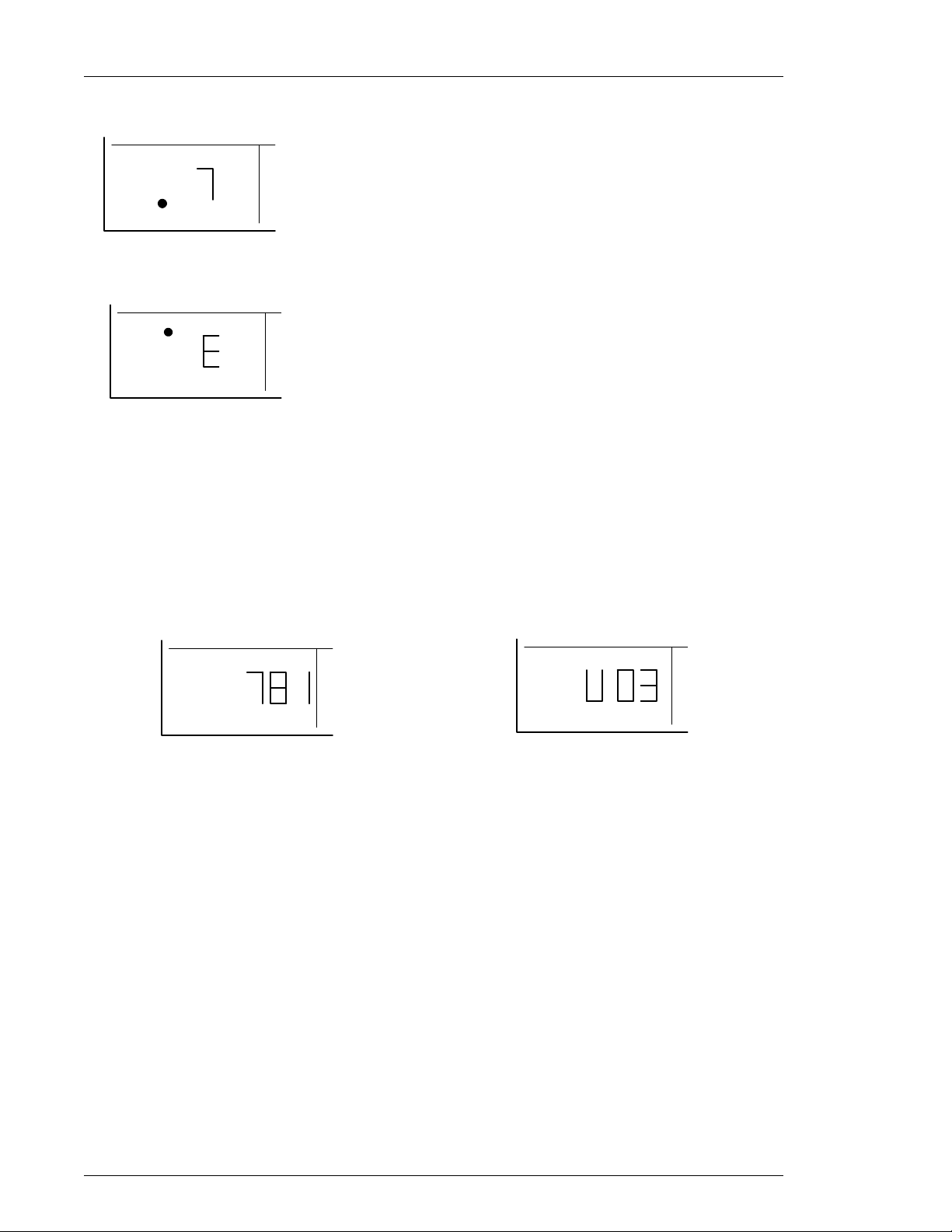
1. Parameter number "2" is shown
PARM
ABN
Page 7-3
Page 4
Chapter 7: System Operations (Rev. 8/98)
2. Abnormal number "7" is shown
PARM
ABN
3. When the CAL switch is pressed, "E" is shown if the FULL-SCALE preset value is
missing or a wrong tool is connected.
PARM
ABN
Indicates the parameter number used for the previous fastening operation. Should an
abnormal condition occur the display will indicate the nature of the abnormality through a code
number (Refer to Chapter 9).
w[ANGL/SPNO] Angle data/Axis unit number indicator.
Display for the final angle value of the previous fastening operation. The angle value is
given in integers numbers. Directly after the power is turned on and while the RESET signal is
active the spindle number is displayed.
ANGLE
SPNO
ANGLE DISPLAY
ANGLE
SPNO
SPINDLE NUMBER
.
Page 7-4
Page 5

Chapter 7: System Operations (Rev. 8/98)
7.1.4 Fastening Presetting / Result Display Controls.
wMODE.
PUsed to change modes while in the Run state. (Refer to 7.2)
PUsed to move the cursor while in the Bypass (program) state. (Refer to 7.3)
wSET.
PUsed to enter the Data Edit mode, and to confirm data setting change.
w[
↑↑↑↑
↓↓↓↓
] and [
] Cursor key (vertical arrows).
PUsed to scroll through available parameter numbers. (PARM)
PUsed to scroll through available data preset items. (D-NO)
PUsed to change display data values. (DATA)
PUsed as YES/NO acknowledge for Tool type and Torque unit changes. (Fig 7-3-8b)
Page 7-5
Page 6
Chapter 7: System Operations (Rev. 8/98)
7.2 Run State Modes.
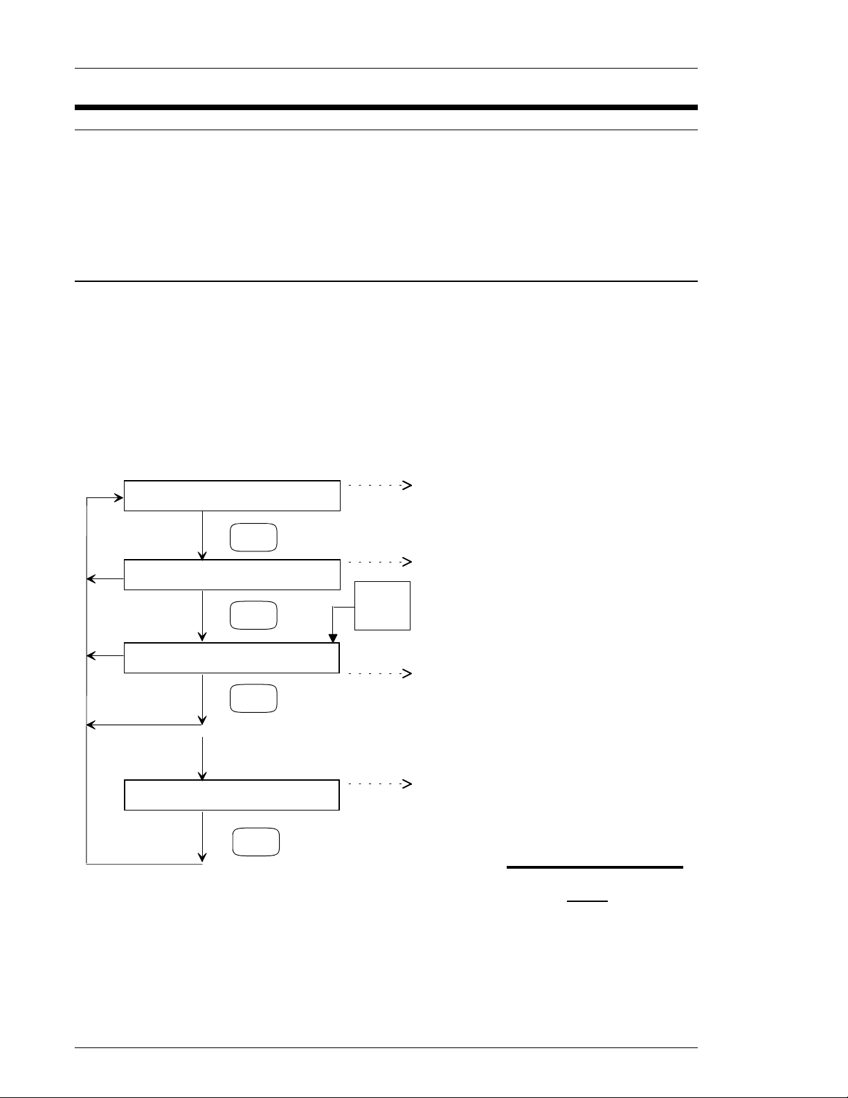
The AFC 1100 system has two operational states that are controlled by the selection of the
Run/Bypass switch on the front of the Axis unit or by the PLC Bypass input. The operational
modes availible in the Run State are identified below. Under this condition the BYPASS
switch on the front panel is in the RUN position and the BYPASS external signal is not active
(the BYPASS LED is off). During the RUN condition, the display mainly shows the results of
fastening, abnormalities, preset values, etc.
7.2.1 Display indication modes.
Three modes can be selected while in the RUN state by pressing the MODE push-button.
By using the [
parameters may be varied. The displays will remain blank, and mode selection will be
disabled while the nutrunner is active. (BUSY)
The Fastening results display mode is active when the D-No displays one digit in the right hand
FASTENING RESULTS DISPLAY MODE
START
PARAMETER DISPLAY MODE
START
REAL TIME DISPLAY MODE
↓↓↓↓
↑↑↑↑
] and [
] keys to change the D-NO selected the DATA Display contents for
location, and one, two or three dashes in the
left hand location. The results' details can
↑↑↑↑
↑↑↑↑
] and [
] and [
be scrolled by using the [
change the D-No. This display does not
function while the nutrunner is Busy.
The Parameter display mode is active
MODE
AT
MODE
MODE
POWER
ON
when the D-No displays digits in both the
right and left hand locations. The
parameter data can be scrolled by using the
↑↑↑↑
[
The Real time display mode is active
when one digit is active in the right hand
display only. When the power is turned on,
the default display mode is the REAL TIME
display mode. The display contents can be
scrolled by using the [
change D-NO.
] and [
↓↓↓↓
] keys to change D-No.
↓↓↓↓
] keys to
↓↓↓↓
] keys to
STATUS DISPLAY
MODE
The Axis unit is in Status display mode
when no digits are displayed. The STATUS
display indicates if an abnormal condition
occurs or if an emergency stop has halted
the system.
FIG. 7-2-1 Run State Display
Modes
Page 7-6
Page 7

7.2.2 Real-time display indication mode.
While the mode is in real-time data indication ([D-NO] shows 0, 1 or 2. You can choose
the desired type of data by pressing the [
The indicator will show the following data in "DATA" AND "ANGL.SPNO" for the selected
D-No..
0
1
2
PTorque value: The real-time (current) torque value on the torque
transducer is shown.
PTorque voltage : The real-time (current) torque signal voltage on the torque
transducer is shown.
PMaximum torque: The peak torque, measured since the last resetting of the
switch within the current mode, is shown.
PAxis unit number: The Axis unit No. as set up on the unit via dip switches
PRotated angle: The real-time angle of rotation of the tool output shaft (in the
fastening direction CW), measured since the last resetting of
the switch within the current mode. (-119
↓↓↓↓
] and [
Chapter 7: System Operations (Rev. 8/98)
↑↑↑↑
] keys to change the [D-NO] (data number).
ANGL.SPNODATAD-No
Axis unit numberTorque value.
Axis unit numberTorque voltage.
Rotated angle.Maximum torque (maximum hold).
°
to 999°).
Key operation during the real-time data indication mode.
Indication shown in "DATA"
DATA
TORQUE VOLTAGE
PEAK TORQUE
FIG. 7-2-2 Real time display selection
OR
D-NO
0
1
2
TORQUE VALUE
(MAXIMUM HOLD)
Page 7-7
Page 8
Chapter 7: System Operations (Rev. 8/98)
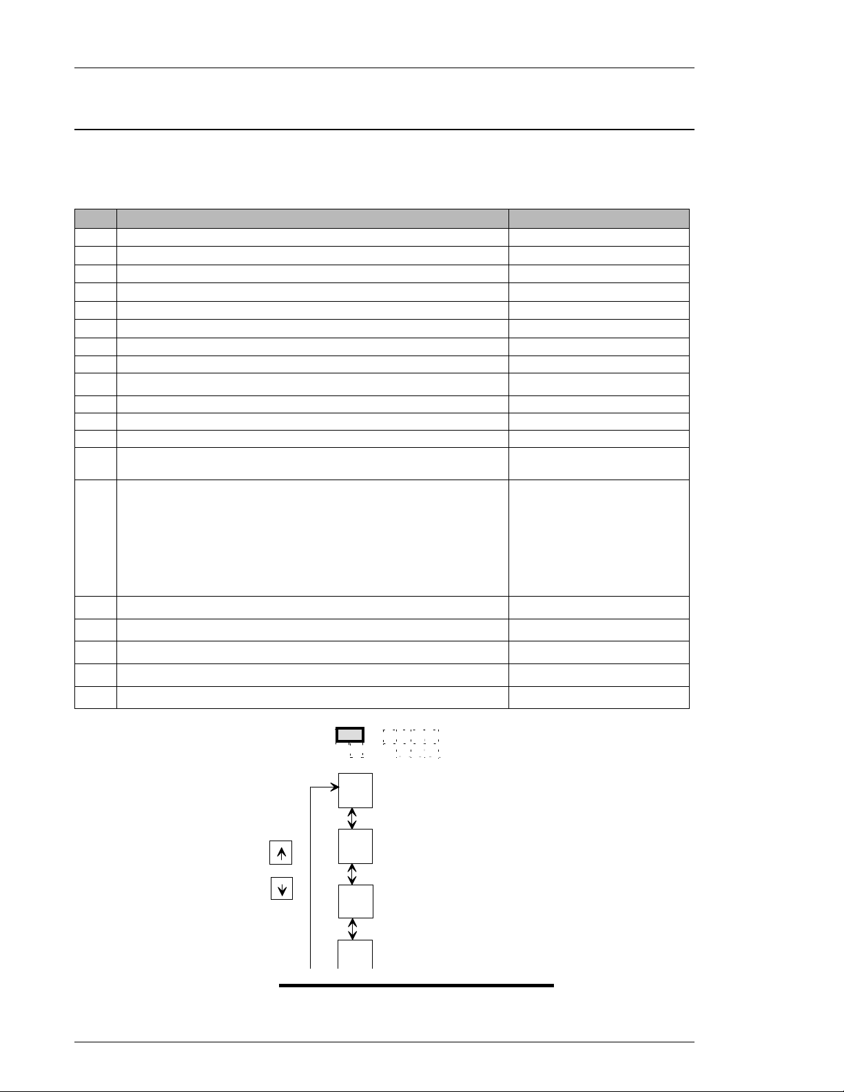
7.2.3 Fastening results display mode.
In fastening results display mode (when [D-NO] shows _0 ~
pressing the [
following information will be displayed in the [DATA] and [ANGL/SPNO] display sections for
the displayed [D-NO]:
_0
_1
_2
_3
_4
_5
_6
_7
0
====
=1
=2
=3
=4
OUT)
=5
0: RESET / NO DATA / AFTER REVERSE.
1: ABNORMAL SIGNAL.
2: BYPASS SIGNAL.
3: STOP SIGNAL.
4: REJECT.
5: ACCEPT.
↓↓↓↓
↑↑↑↑
] and [
] keys to scroll [D-NO] until the desired DATA item is displayed. The
≡≡≡≡0
1
≡≡≡≡
2
≡≡≡≡
3
≡≡≡≡
4
≡≡≡≡
D-NO
DATA
ANG/SPNO
4), data can be obtained by
≡≡≡≡
ANGL/SPNODATAD-No
FINAL ANGLE.PEAK TORQUE.
SPINDLE NO.FINAL ANGLE
SPINDLE NO.1ST TORQUE RATE
SPINDLE NO2ND TORQUE RATE.
SPINDLE NO.1ST STEP TIME.
SPINDLE NOFINAL STEP TIME.
SPINDLE NOCYCLE TIME
SPINDLE NOFASTENING MODE.
SPINDLE NOFASTENING MODE.
SPINDLE NOFASTENING STEPS
SPINDLE NONOT USED
SPINDLE NOSELF CHECK (ON: enabled, OFF: disabled)
SPINDLE NOREVERSE FLAG (ON: BACKED OUT, OFF: NOT BACKED
SPINDLE NOCAUSE OF FASTENING STOP:
1ST INCREMENT ANGLE.1ST INCREMENT TORQUE.
2ND INCREMENT ANGLE.2ND INCREMENT TORQUE.
1ST FINAL ANGLE.1ST FINAL TORQUE
1ST PEAK ANGLE.1ST PEAK TORQUE.
ANGLE @ PEAK TORQUE.FINAL TORQUE.
(DISPLAY [D-No]
_0
_
_1
OR
_2
_3
FIG. 7-2-3 Fastening results display selection
DATA DISPLAYED
PEAK TORQUE
FINAL ANGLE
1ST TORQUE RATE
2ND TORQUE RATE
Page 7-8
Page 9
7.2.4 Parameter display mode
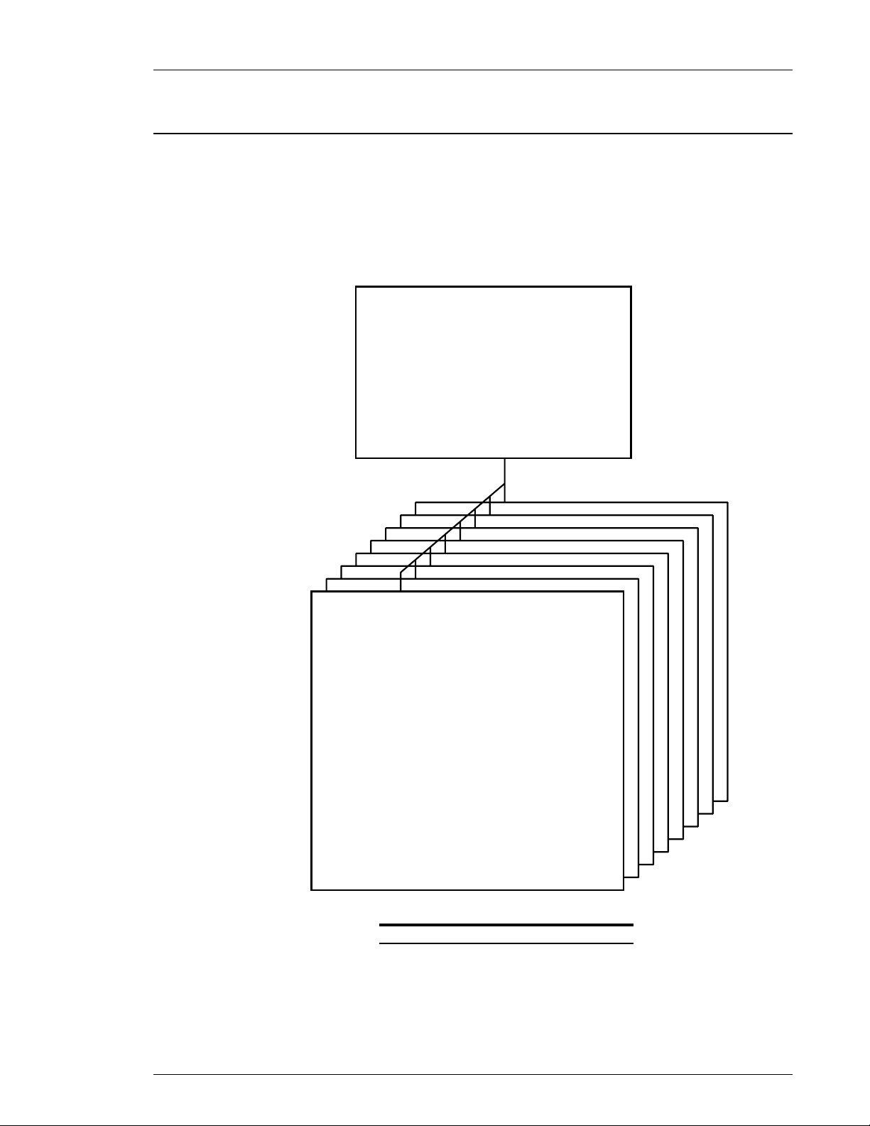
Parameter means a group of values that configures a fastening operation. Combined these
values are named preset data. The AFC1100 system can store up to 8 different parameters
that can be selected by WORK SELECT 0 ~ 2 (see section 4.7.2) PLC inputs.
In addition to parameter 1 ~ 8 there is a PARAMETER 0 that contains configuration data
common to all parameters.
Chapter 7: System Operations (Rev. 8/98)
SYSTEM PARAMETERS
TORQUE UNIT: Kg-m, Kg-cm, Nm, Ft-Lb, In-Lb
PARAMETER 1-8, when using the same tool setting..
TOOL SETTINGS used with PARAMETER 1
TOOL SETTINGS used with PARAMETER 2
TOOL SETTINGS used with PARAMETER 3
TOOL SETTINGS used with PARAMETER 4
TOOL SETTINGS used with PARAMETER 5
TOOL SETTINGS used with PARAMETER 6
TOOL SETTINGS used with PARAMETER 7
TOOL SETTINGS used with PARAMETER 8
PARAMETER 0
(PRESET VALUES)
CAL TORQUE
LOW TORQUE
HIGH TORQUE
STD TORQUE
SPEED CHANGE TORQUE
1ST TORQUE
SNUG TORQUE
THR TORQUE
CROSSOVER TORQUE
LOW ANGLE
HIGH ANGLE
FINAL ANGLE
1ST ANGLE
CROSSOVER ANGLE
1ST TORQUE RAT E L O W
1ST TORQUE RAT E HIG H
2ND TORQUE RATE HIGH
2ND TORQUE RATE LO W
INITIAL TIME
1ST TIME
FINAL TIME
FREE RUN SPEED
SLOW DOWN SPEED
TORQUE SPEED
REVERSE SPEED
FREE RUN TURN
PARAMETER 1
8
7
6
5
4
3
2
FIG. 7-2-4a Parameter number selection
Page 7-9
Page 10
Chapter 7: System Operations (Rev. 8/98)
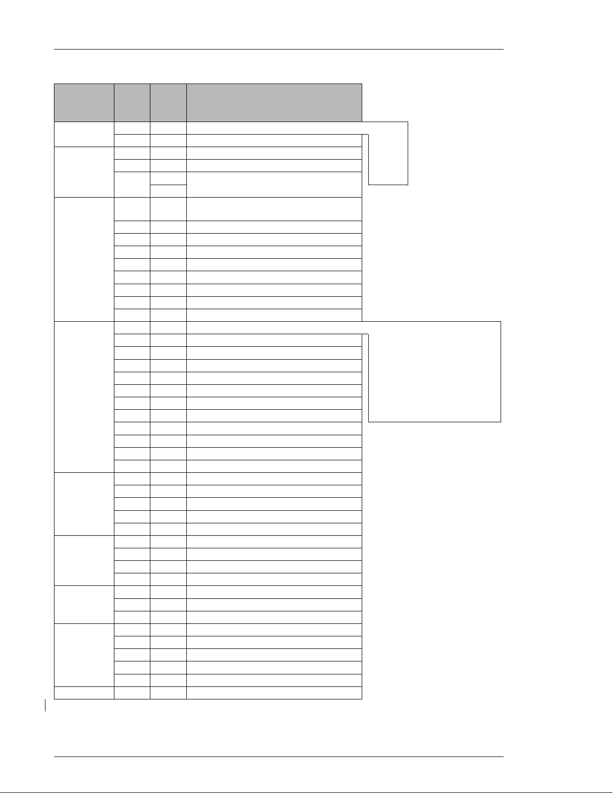
D- No
ITEM
* Displayed in PARM/ABN display. ** Displayed in D-NO display. *** Display in DATA display.
*
PARM
No.
0System.
0
0Tool Data.
0
0
0Tool type.
0
0
0
0
0
0
0
0
1~8Torque.
1~8
02
1~8
1~8
1~8
1~8
1~8
1~8
1~8
1~8
1~8
1~8Angle
1~8
1~8
1~8
1~8
1~8Rate
1~8
1~8
1~8
1~8Time
1~8
1~8
1~8Speed
1~8
1~8
1~8
1~8
1~8Revolutions
DATA
**
00
01
10
11
12
1A
TOOL # (When parameters use the
20
same tool).
PARAMETER 1 TOOL #
21
PARAMETER 2 TOOL #
22
PARAMETER 3 TOOL #
23
PARAMETER 4 TOOL #
24
PARAMETER 5 TOOL #
25
PARAMETER 6 TOOL #
26
PARAMETER 7 TOOL #
27
PARAMETER 8 TOOL #
28
00
01
10
11
12
13
14
1ST TORQUE
15
SNUG TORQUE
16
THR TORQUE
17
CROS TORQUE
18
LOW ANGLE LIMIT
20
HIGH ANGLE LIMIT
21
STD ANGLE
22
1ST ANGLE
23
CROS ANGLE (2nd torque rate start).
24
1ST TORQUE RATE LOW LIMIT
30
1ST TORQUE RATE HIGH LIMIT
31
2ND TORQUE RATE LOW LIMIT
32
2ND TORQUE RATE HIGH LIMIT
33
INITIAL TIME
40
1ST STEP TIME
41
FINAL TIME
42
INITIAL SPEED
50
FREE RUN SPEED
51
SLOW DOWN SPEED
52
TORQUE SPEED
53
REVERSE SPEED
54
FREE RUN REVOLUTIONS
60
***
0: NmTORQUE UNIT #.
1: Kg.mROM VERSION (Not adjustable)
2: kgcmTOOL # (not adjustable)
3: ftlbTOOL CAL TORQUE.
4: inlbCOMPANY'S SUPERVISOR DATA.
CW torque, 1 step 0010FASTENING MODE (method + steps)
CW angle, 1 step 0011FASTENING METHOD
CW torque, 2 step 0020STEP
CW angle, 2 step 0021FULL SCALE TORQUE
CCW torque, 1 step 0110TORQUE LOW LIMIT
CCW angle, 1 step 0111TORQUE HIGH LIMIT
CCW torque, 2 step 0120STD TORQUE
CCW angle, 2 step 0121SPEED CHANGE
Page 7-10
Page 11
Chapter 7: System Operations (Rev. 8/98)
D-NO
(DISPLAY [D-No]
OR
DATA
00
_
10
11
12
.
.
.
.
54
DISPLAYS THE FOLLOWI NG DATA
PARA 0 TORQUE UNIT
PARA 0 TOOL #
PARA 0 TOOL CALIBRATION TORQUE
COMPANY'S DATA
PARA 0 FEC USE ONLY
PARA 1 ~ PARA 8
PARA 8 REVERSE SPEED
60
PARA 8 FREE RUN BOLT THREAD COUNT
FIG. 7-2-4b Parameter display D-No selection
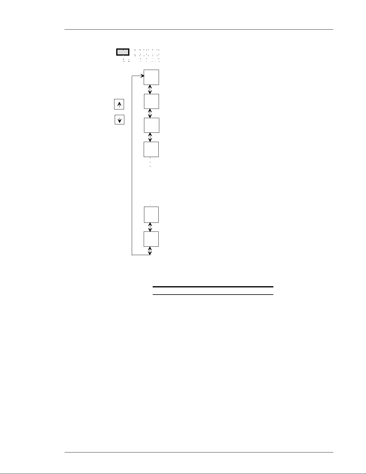
When parameter display mode is on, the [D-No] display will show 2 digits (00-60) representing the
preset data number. The [DATA] display will show the corresponding preset data value and the
parameter display [PARM] will indicate the parameter number (from 0 ~ 8). Use the [
↓↓↓↓
to change the preset data number [D-NO]. If the [D-NO] display is showing the number 60 of the
parameter number 1, pressing the [
↑↑↑↑
] key will change the [D-NO] display to the number 00 of the
parameter number 2.
You can verify the fastening parameters by pressing the [
↓↓↓↓
] and [
↑↑↑↑
] keys. It is not possible to alter
these settings (RUN state).
] and [
↑↑↑↑
] keys
Page 7-11
Page 12
Chapter 7: System Operations (Rev. 8/98)
7.2.5 STATUS display
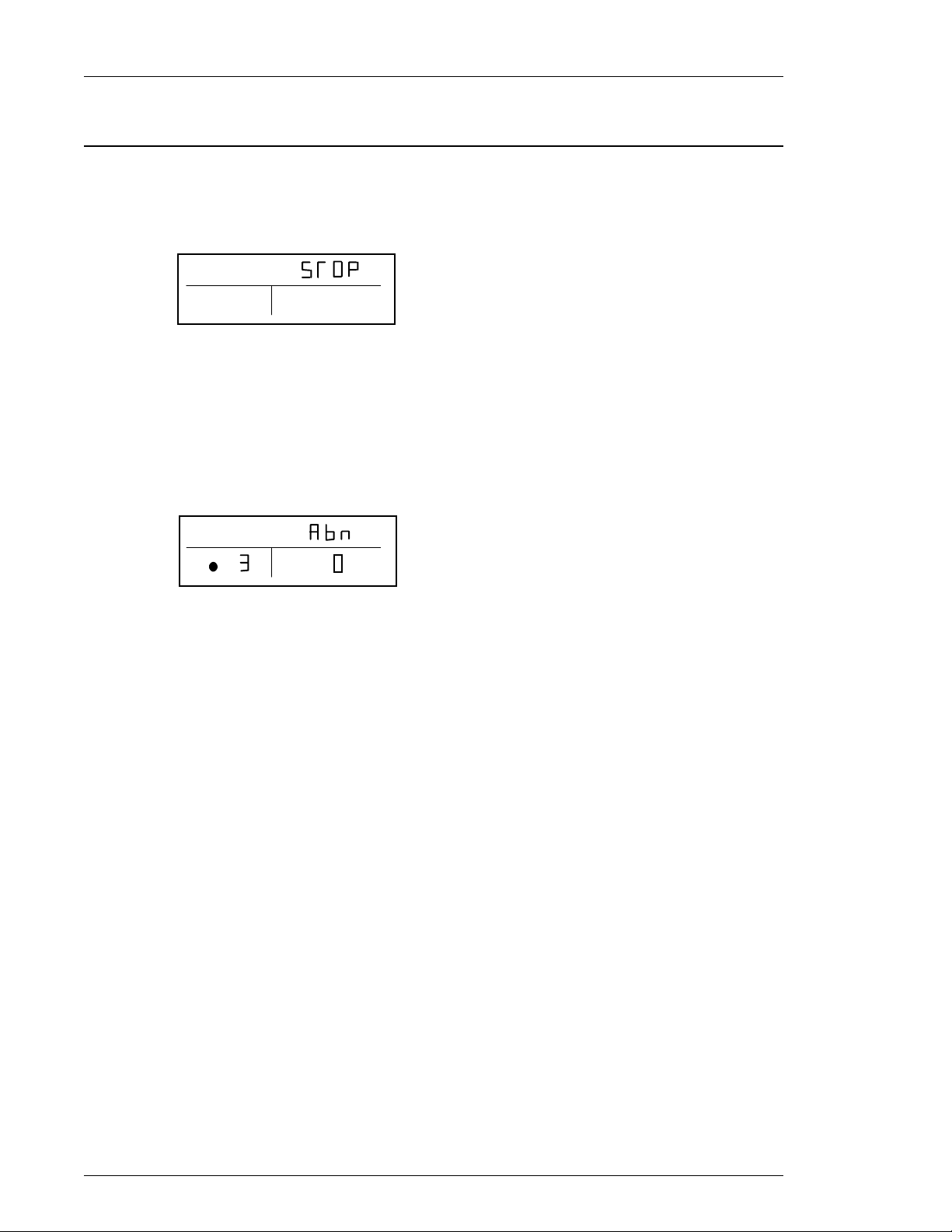
This display will indicate when the STOP signal has halted the AFC 1100. The STATUS
display will indicate conditions as shown below (the [D-NO] display is not active).
1) When the STOP signal is activated:
The [DATA] display will show STOP.
D-NO
DATA
PARM/
ABN
2) When an abnormal condition occurs:
The [DATA] display will show ABN.
The display will indicate ABN and the ANGL/SPNO display will show the corresponding
SERVICE CODE #.
This shows a case where the abnormal number is 3 and the service code is 0. (Refer to
chapter 9)
D-NO DATA
PARM/
ABN
ANGL
SPNO
ANGL
SPNO
Page 7-12
Page 13
7.3 Bypass state operation.
The AFC 1100 system has two operational states that are controlled by the selection of the
Run/Bypass switch on the front of the Axis unit or by the PLC Bypass input. The operational
modes availible in the Bypass State are identified below. Under this condition the BYPASS
switch on the front panel is in the BYPASS position or the BYPASS external signal is active
(the BYPASS LED is on). During the BYPASS condition, the display shows preset values.
7.3.1 Download Mode selection
Immediately after the bypass condition has been entered, the unit is in the download mode,
which allows the system to be set up by a user console via the RS-422 port. Press the
[MODE] key to change from the download mode to the setup mode. If the Axis unit is
performing some data communication to an external computer, the download mode will be
maintained until the operation is completed.
7.3.2 Setup Mode selection
Depressing the Mode button will initiate the Setup mode. Immediately after the setup mode
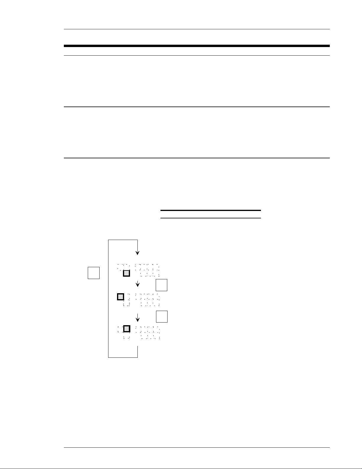
is established, a blinking number will appear in the [PARM/ABN] display. This number can be
changed with the [
↓↓↓↓
will show the number corresponding to the [DATA] display function while the [DATA] display
will show the actual value as it is currently set. You may change the currently indicated data
using the Data Edit mode
] and [
↑↑↑↑
] keys to select a different parameter number. The [D-NO] display
Chapter 7: System Operations (Rev. 8/98)
FIG. 7-3-2 Setup mode D-No selection
D-NO
MODE
key
MODE
key
key
DATA
PARAMETER No
DATA
DATA NUMBER (left digit)
DATA
DATA NUMBER (right digit)
MODE
MODE
key
D-NO
D-NO
The cursor (blinking mode) will move each time the [MODE] key is pressed.
Press the [SET] key to enter into the Data Edit mode.
Page 7-13
Page 14
Chapter 7: System Operations (Rev. 8/98)
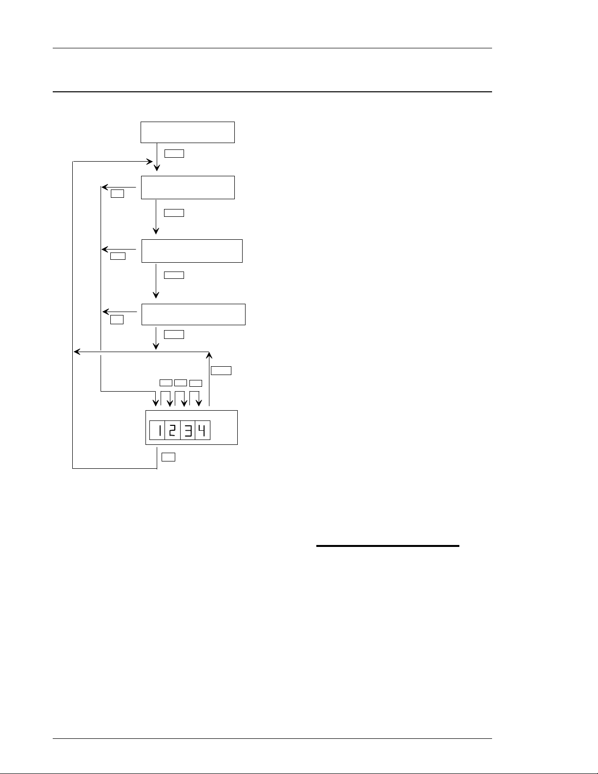
7.3.3 Setup mode operation.
SET
SET
SET
U.XX
AXIS UNIT INDICATION
MODE
PARAMETER NUMBER
SELECTION
MODE
Depressing the [MODE] switch will bring up the
setup mode. A blinking digit will appear in the
[PARM] display specifying the cursor position.
Use the [
↓↓↓↓
] and [
↑↑↑↑
] keys to select the desired
parameter number.
Press the [SET] key to enter the Data Edit mode,
where you can change the values appearing in the
DATA NUMBER SELECTION
(left digit)
MODE
DATA NUMBER SELECTION
(right digit)
MODE
DATA EDIT
MODE
MODE
MODE
MODE
MODE
[DATA] display section or press [MODE] to select a
different [DATA] display function.
Use the arrow keys to change the data number.
(Data Number Correspondence Chart, section
7.3.6)
Pressing the [MODE] key Moves the cursor.
Pressing it four times causes the system to exit out
DATA
of the edit mode, returning to the parameter
number selection without saving any changes. Use
the [
↓↓↓↓
] and [
↑↑↑↑
] keys to decrease or increase the
value number.
SET
Pressing the [SET] key will enter the new values
shown in the DATA display. If the entered values
are inappropriate, "Err" will appear, and the new
data will be ignored. In this case return to the
parameter number selection (using the [MODE]
key) and retry.
FIG. 7-3-3 Setup mode operation
When the torque unit number or the tool type is changed, the [DATA] display will show
"CHNG," and the ANGL.SPNO display will show "NO." Use the vertical arrow keys to choose
YES or NO; YES means that the data will be entered if the confirmation SET key is pressed.
The [SET] and [MODE] switches will have no effect when "NO" appears. If no key is pushed
in five seconds, the new data will be ignored, and the system will exit the Data Edit mode
.
Warning:
When the torque unit (PARM 0, and D-NO 00) or the tool type (PARM 0, and D-No
20-28) is changed, the torque (D-No 00-18) and the speed (D-No 50-54) will be cleared.
Page 7-14
Page 15
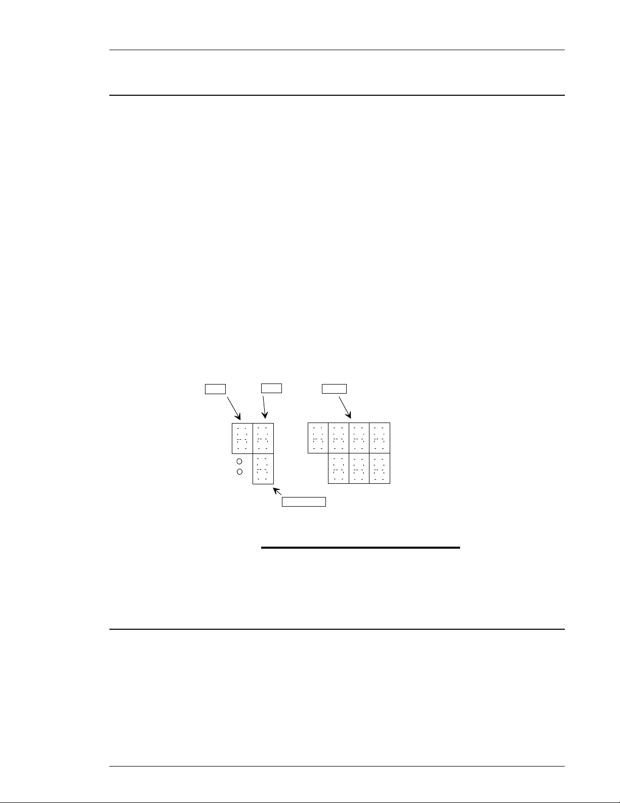
7.3.4 Parameter # selection
When the cursor is in the PARM/ABN display, the settings can be changed from 0 ~ 8 with
↓↓↓↓
the [
Data corresponding to the selected parameter number will be displayed in the [DATA]
display.
] and [
↑↑↑↑
] keys.
Chapter 7: System Operations (Rev. 8/98)
w
D-No
1
D-No
PARM
ABN
7.3.5 Data # selection
D-No
2
DATA
ANGL
SPNO
PARM.ABN
FIG. 7-3-4 Parameter display D-No selection
DATA
The value for digit 1 and 2 of the [D-No] display may only be changed when the cursor is in
the respected position. The [D-NO] value is changed with the [
corresponding to the data number [D-NO] display will appear in the [DATA] display (Refer to
section 7.3.6).
Page 7-15
↓↓↓↓
] and [
↑↑↑↑
] keys. Data
Page 16
Chapter 7: System Operations (Rev. 8/98)
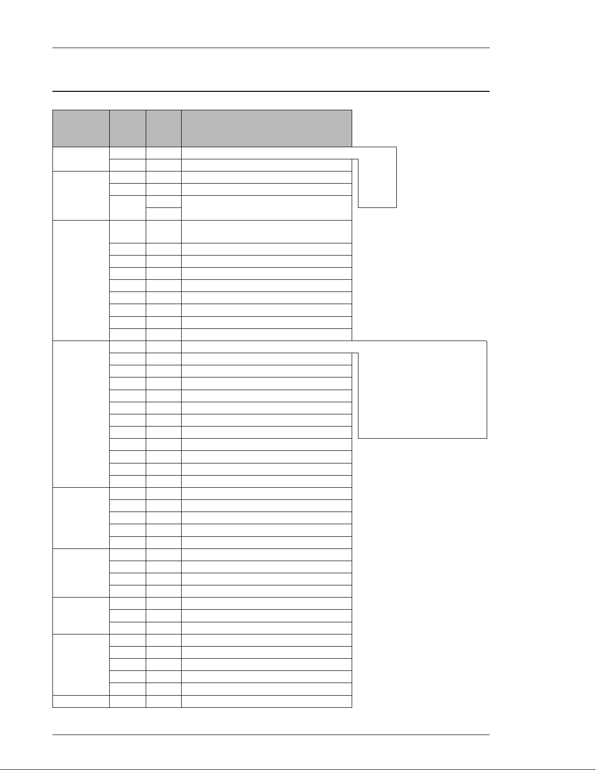
7.3.6 Data number correspondence chart
Relationship of the PARAMETER #, DATA # and PARAMETER DATA (preset data).
D- No
ITEM
*
PARM
No.
0System.
0
0Tool Data.
0
0
0Tool type.
0
0
0
0
0
0
0
0
1~8Torque.
1~8
02
1~8
1~8
1~8
1~8
1~8
1~8
1~8
1~8
1~8
1~8Angle
1~8
1~8
1~8
1~8
1~8Rate
1~8
1~8
1~8
1~8Time
1~8
1~8
1~8Speed
1~8
1~8
1~8
1~8
1~8Revolutions
Please see Chapter 9 for parameter setting examples.
DATA
**
00
01
10
11
12
1A
TOOL # (When parameters use the
20
same tool).
PARAMETER 1 TOOL #
21
PARAMETER 2 TOOL #
22
PARAMETER 3 TOOL #
23
PARAMETER 4 TOOL #
24
PARAMETER 5 TOOL #
25
PARAMETER 6 TOOL #
26
PARAMETER 7 TOOL #
27
PARAMETER 8 TOOL #
28
00
01
10
11
12
13
14
1ST TORQUE
15
16
17
18
20
HIGH ANGLE LIMIT
21
STD ANGLE
22
1ST ANGLE
23
CROS ANGLE (2nd torque rate start).
24
1ST TORQUE RATE LOW LIMIT
30
1ST TORQUE RATE HIGH LIMIT
31
2ND TORQUE RATE LOW LIMIT
32
2ND TORQUE RATE HIGH LIMIT
33
INITIAL TIME
40
1ST STEP TIME
41
FINAL TIME
42
INITIAL SPEED
50
FREE RUN SPEED
51
SLOW DOWN SPEED
52
TORQUE SPEED
53
REVERSE SPEED
54
FREE RUN REVOLUTIONS
60
***
0: NmTORQUE UNIT #.
1: Kg.mROM VERSION (Not adjustable)
2: kgcmTOOL # (not adjustable)
3: ftlbTOOL CAL TORQUE.
4: inlbCOMPANY'S SUPERVISOR DATA.
Refer to following
page for tool list.
CW torque, 1 step 0010FASTENING MODE (method + steps)
CW angle, 1 step 0011FASTENING METHOD
CW torque, 2 step 0020STEP
CW angle, 2 step 0021FULL SCALE TORQUE
CCW torque, 1 step 0110TORQUE LOW LIMIT
CCW angle, 1 step 0111TORQUE HIGH LIMIT
CCW torque, 2 step 0120STD TORQUE
CCW angle, 2 step 0121SPEED CHANGE
Fastening method SNUG TORQUE
and step are setTHR TORQUE
automatically via CROS TORQUE
Fastening mode.LOW ANGLE LIMIT
Page 7-16
Page 17
Chapter 7: System Operations (Rev. 8/98)
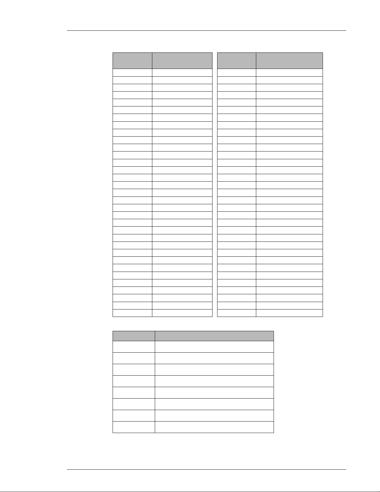
w1) Tool type input items.
TOOL NAMETOOL
NUMBER
DFT-802M4-S11
DFT-802W4-S12
DFT-203N1-S113
DFT-403N1-S14
DFT-502M4-S15
DFT-153N1-S16
NUMBER
DFT-802M4-O111
DFT-802W4-O112
DFT-203N1-O113
TOOL NAMETOOL
DFT-051M1-SR201DFT-051M1-S1
DFT-101M1-SR202DFT-101M1-S2
DFT-201M1-SR203DFT-101M1-S13
DFT-401M1-SR204DFT-201M1-S4
DFT-401M2-SR205DFT-401M1-S5
DFT-801M3-SR206DFT-401M2-S6
DFT-132M3-SR207DFT-801M3-S7
DFT-202M3-SR208DFT-132M3-S8
DFT-302M3-SR209DFT-202M3-S9
DFT-802M4-SR210DFT-302M3-S10
DFT-051M1-OR301DFT-051M1-O101
DFT-101M1-OR302DFT-101M1-O102
DFT-201M1-OR303DFT-101M1-O1103
DFT-401M1-OR304DFT-201M1-O104
DFT-401M2-OR305DFT-401M1-O105
DFT-801M3-OR306DFT-401M2-O106
DFT-132M3-OR307DFT-801M3-O107
DFT-202M3-OR308DFT-132M3-O108
DFT-302M3-OR309DFT-202M3-O109
DFT-802M4-OR310DFT-302M3-O110
DFT-502M4-O115
DFT-153N1-O116
2) Fastening mode and fastening steps.
FASTENING MODE / STEPSSET VALUE
0010
0011
0020
0021
0110
0111
0120
0121
CW TORQUE CONTROL, 1 STEP.
CW ANGLE CONTROL, 1 STEP.
CW TORQUE CONTROL, 2 STEP.
CW ANGLE CONTROL, 2 STEP.
CCW TORQUE CONTROL, 1 STEP.
CCW ANGLE CONTROL, 1 STEP.
CCW TORQUE CONTROL, 2 STEP.
CCW ANGLE CONTROL, 2 STEP.
Page 7-17
Page 18
Chapter 7: System Operations (Rev. 8/98)
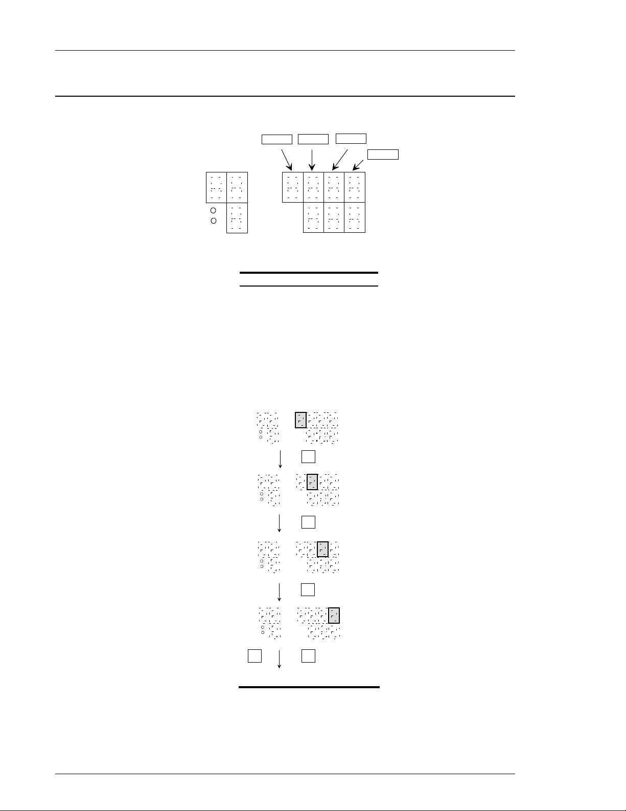
7.3.7 Data Edit Mode.
DATA 1
DATA 2 DATA 3
DATA 4
D-No
PARM
ABN
DATA
ANGL
SPNO
FIG. 7-3-7a Data edit positions
The cursor will appear in the [DATA] display when the machine is in DATA EDIT mode. In
the DATA EDIT mode the MODE key is used as the cursor key. When the MODE key is
pressed, the cursor moves from the 1st data field (at the left) to the 4th data field (right). The
↓↓↓↓
[
] and [
↑↑↑↑
] keys can be used at any position to change or enter data. Once the cursor is in the
last data field (4th), pressing the MODE key returns the system to the PARAMETER
SELECTION mode without finalizing the data. Data that has been entered in DATA EDIT
mode and confirmed with the [SET] key will be displayed.
D-No
PARM
ABN
D-No
PARM
ABN
DATA
ANGL
SPNO
DATA
ANGL
SPNO
MODE
KEY
MODE
KEY
D-No
PARM
ABN
D-No
PARM
ABN
DATA SAVE
PARAMETER SELECTION MODE
DATA
ANGL
SPNO
DATA
ANGL
SPNO
MODE
KEY
MODE SET
KEYKEY
NO DATA SAVE
FIG. 7-3-7b Data edit operation
Values in the DATA fields can be changed from 0~9 in the DATA EDIT mode using the [
↑↑↑↑
and [
] keys. Once the values have been selected, pressing the [SET] key saves them and
returns you to PARAMETER CHANGE mode.
Page 7-18
↓↓↓↓
]
Page 19
7.3.8 Data setup procedure.
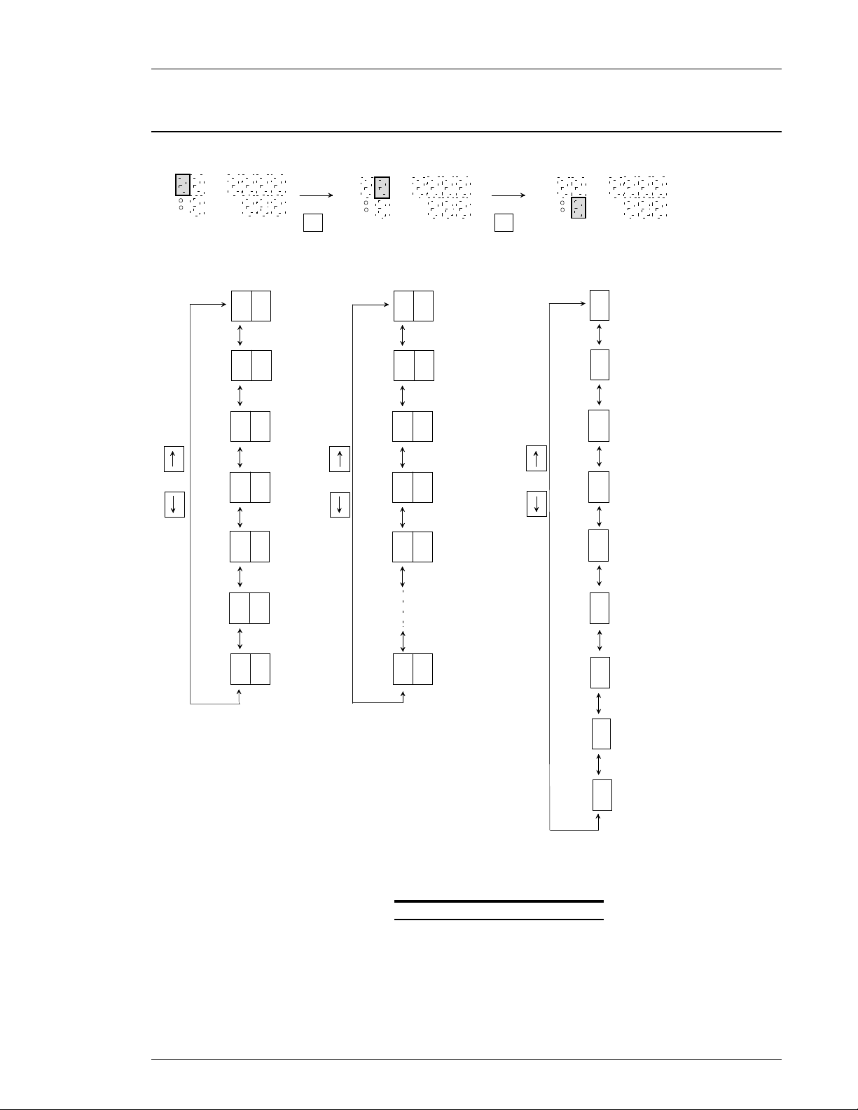
Changing Data numbers by the Setup mode.
Chapter 7: System Operations (Rev. 8/98)
D-No
PARM
ABN
DATA
ANGL
SPNO
DISPLAY [D-NO]
0
1
2
OR
3
4
D-No
PARM
ABN
DATA
ANGL
SPNO
DISPLAY [D-NO]
MODEMODE
0
1
2
OR
3
4
D-No
PARM
ABN
OR
DATA
ANGL
SPNO
DISPLAY [PARM/ABN]
0
SYSTEM SET DATA
PARAMETER NUMBER 1
1
PARAMETER NUMBER 2
2
PARAMETER NUMBER 3
3
PARAMETER NUMBER 4
4
5
6
9
FIG. 7-3-8a Data setup procedure
5
6
7
8
PARAMETER NUMBER 5
PARAMETER NUMBER 6
PARAMETER NUMBER 7
PARAMETER NUMBER 8
Page 7-19
Page 20
Chapter 7: System Operations (Rev. 8/98)
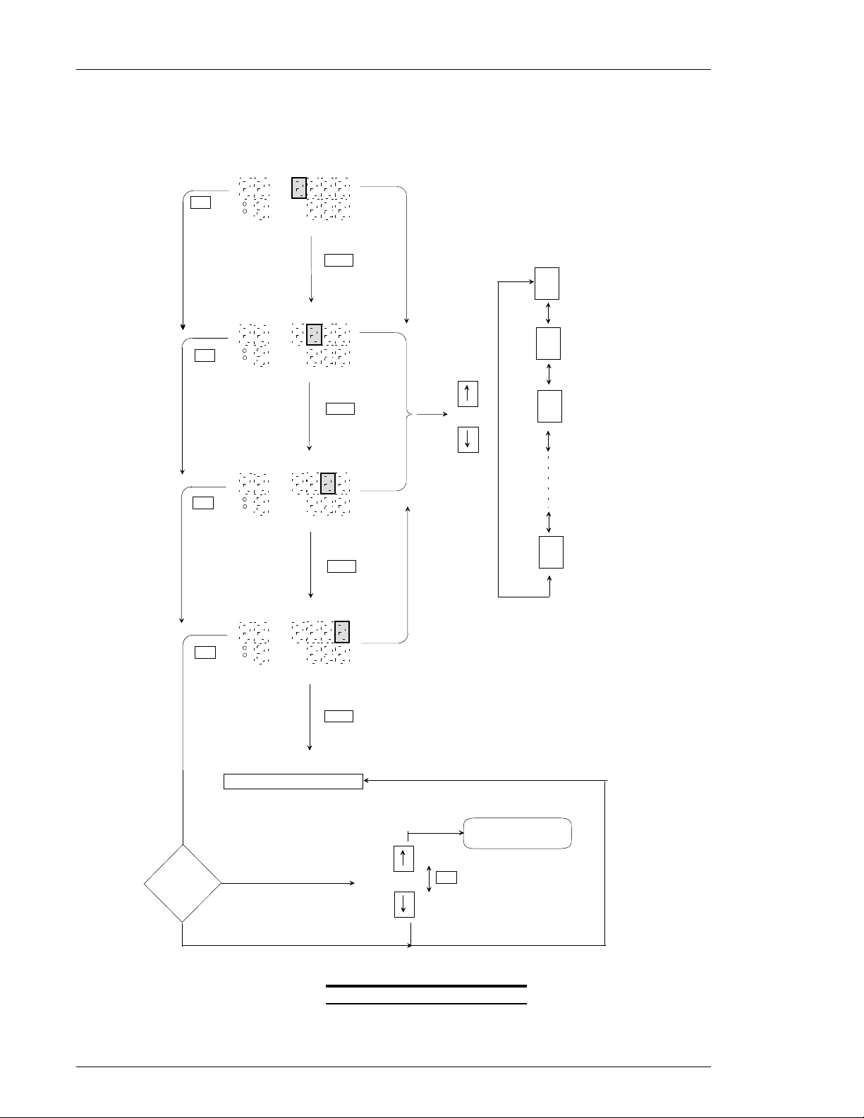
wData Edit Mode key operations / example.
SET
SET
SET
D-No
PARM
ABN
D-No
PARM
ABN
D-No
PARM
ABN
DATA
ANGL
SPNO
DATA
ANGL
SPNO
DATA
ANGL
SPNO
MODE
Change digit
MODE
Change digit
OR
CHANGE
DATA
[DATA] display
0
1
2
9
MODE
Change digit
Data was changed
HAS
THE TOOL
TYPE OR
TORQUE UNIT
CHANGED
?
NO
D-No
PARM
SET
ABN
Return to the SETUP MODE
YES
DATA
ANGL
SPNO
SET DATA
Data was not changed
MODE
TORQUE AND SPEED DATA
CHNG
YES
OR
CHNG
NO
MUST BE REENTERED
SET
Tool type or torque unit were not changed.
FIG. 7-3-8b Data setup example
.
Page 7-20
Page 21

7.4 Calibration adjustment.
The calibration value is set according to the tool type (capacity). However, depending on
the application characteristics or on the prevailing torque generated by the spindle assembly,
the value of the current torque and the torque display by the Axis unit may mismatch. In this
case it is possible to adjust the FULL SCALE TORQUE (CAL) value, so the displayed torque
matches the real value registered by an external torque transducer (Master).
The CAL value can be adjusted up to ± 10% of the FULL SCALE TORQUE value.
Example:
Let's consider the DFT-801M3-S tool.
Nominal CAL value = 8.0 Kg.m.
Range of adjustment: from 7.2 Kg.m to 8.8 Kg.m.
The torque unit must be the same for all terms.
The FULL SCALE TORQUE value is read from Parameter 1 ~8 D-No 10.
Use the following formula on a collection of at least 10 fastenings when a calibration
correction is necessary:
Chapter 7: System Operations (Rev. 8/98)
New CAL value = Master transducer mean/ FEC transducer mean x Existing CAL
value
If the new CAL value is out of the adjustable range, the [Err] message will be displayed in
the [ANGL/SPNO] display.
Example.
Tool Full Scale value (EXISTING CAL)is 78.4 Nm.
STD torque is 49.0 Nm.
Master transducer mean for 10 piece run is measuring only 47.5 Nm.
FEC transducer mean for 10 piece run is measuring 49.0 Nm.
The new CAL value is obtained as follows:
(47.5/49.0 x 78.4) = 76.0
The FULL SCALE TORQUE (CAL) value must be corrected to 76.0 Nm.
Page 7-21
 Loading...