


AFC1500
AFC 1500 Multi Unit
1
Hardware Manual
Version 2.04
(Compatible with AFC User Console Software Version 3.61 and above)
April 2003
51327 Quadrate Drive Macomb, MI. 48042
Ph. 586.781.2100 Fax 586.781.0044
www.fec-usa.com

*** WARNING ***
All applicable National and local codes must be followed when installing
and operating the equipment detailed in this manual.
FAILURE TO ABIDE BY THESE CODES AND THE SPECIFICATIONS
DESCRIBED IN THIS MANUAL CAN RESULT IN SERIOUS INJURY TO
PERSONNEL AND/OR DAMAGE TO THE EQUIPMENT.
*** WARNING ***
THIS EQUIPMENT IS CAPABLE OF HIGH VOLTAGES HAZARDOUS TO HUMAN LIFE.
**
Turn off and lock-out all voltage sources prior to performing any work on this equipment.
**
Do not open or remove any covers, even if the Unit is disconnected from the power source.
**
Only qualified personnel should attempt to modify or repair this product.
**
There is a possibility of receiving an electrical shock from this equipment, if used improperly.
**
This System is designed to operate on 200 VAC. Injury or damage could result from using
improper voltage.
**
OPERATOR AND EQUIPMENT SAFETY
Read this manual carefully before attempting to operate the equipment.
**
If this System is being operated as a part of a larger system, the larger system should be
**
clearly marked with the warning information, above. Also, a copy of this notice should be
included in all pertinent operations and maintenance manuals. At a minimum, Controller
Units must be placed in a NEMA 12 / IP52 enclosure. Some type of Air Handling Unit (air
**
conditioner, heat exchanger, etc.) may also be required.
Be sure to use the recommended circuit breakers with the power supply lines.
**
Use the power supply voltages recommended in the specifications to prevent possible
**
personnel injury and equipment damage.
Do not modify this equipment, or the warranty will be void. Please contact FEC INC. if any
**
special modification is required.
Inspect the equipment for wear and damage at regular intervals.
**
Specific precautions regarding equipment installation and location have been incorporated
**
into this manual. Before operating the equipment, verify that countermeasures have been
taken for any adverse conditions that may exist.
Failure to address these conditions prior to operation could result in damage to the
**
equipment.
Any questions regarding the contents of this document or any related matter should be
directed to FEC INC. at (586) 781-2100. Requests may be faxed to FEC INC. Product
Engineering at (586) 781-0044.
Unauthorized reproduction or distribution of this manual is strictly prohibited. Please contact
FEC INC. if you require additional copies.

Table of Contents
.....................................
.
3
Table of Contents
Multi Unit Outline
.........................................
..........................................
3
7
Functions Outline
Sequence Control ..........................................
Parameter Programming ...................................
Fastening Data Monitoring & Communication ................
General Status Indication ...................................
Specifications
...................................................
.......................................................
Installation Requirements
Installation Environment ...................................
Static Electricity ..........................................
Cleaning .................................................
Handling and Shipping ....................................
Unit Description
Basic Dimensions .........................................
Description of Unit ........................................
....................................................
Setup and Wiring
Multi Unit Installation
Power Input ..............................................
Power wiring reference ....................................
..............................................
.........................................
.........................................
8
8
8
8
9
9
10
10
10
10
10
11
12
13
15
16
16
17
Multi Unit connection
RS485 Communication Port ................................
RS485 port connection ....................................
Serial Communication Ports ...............................
Output Data Available .....................................
Data Output Example
..............................................
18
18
19
20
22
23

....................................
.
Control Interfaces
........................................
25
Interface Board Setup
Discrete I/O Interface
Input/Output Signals ......................................
Input Signals (Connector PLC1) ............................
Output Signals (Connector PLC2) ...........................
Bank Select Outputs .......................................
Discrete Signal Connection ................................
Standard I/O Cable - Wire Color Code .......................
..............................................
..............................................
InterBus S Interface Board
Indication LED ............................................
Termination ..............................................
DeviceNet Interface board
Termination ..............................................
EDS File ..................................................
Indication LED ............................................
Profibus Interface Board
Termination ..............................................
GSD File ..................................................
Indication LED ............................................
Node Address ............................................
Configuration .............................................
.........................................
.........................................
...........................................
26
28
29
29
30
30
31
32
33
34
35
36
37
38
38
39
40
40
41
41
41
Mitsubishi CC-Link
Termination ..............................................
Indication LED ............................................
Configuration ............................................
.................................................
Allen Bradley Remote I/O Interface board
Termination ..............................................
Indication LED ............................................
Fieldbus I/O Assignment
ANYBUS-S Reference
AnyBus S Initialization
..............................................
.........................
...........................................
42
43
45
45
46
47
48
49
50
50

AnyBus - DT Reference
5
AnyBus DT Initialization ...................................
............................................
Input / Output Signals & Fastening Data Outline
...
51
51
53
Multi Unit Input Signals
Sequence Select Table ....................................
Multi Unit Output Signals
Bank Select Procedure ....................................
Multi Unit Output signals ...................................
Signal Timing
Sequence Select Timing ...................................
......................................................
............................................
..........................................
Output signals from the SAN Servo Controllers
Typical I/O Layout
Abnormal Code
..................................................
.....................................................
..................
54
55
56
56
57
58
59
60
61
63

(This page intentionally left blank)

Multi Unit Outline
Œ
In this chapter
The Multi Unit is a complementary device to
enhance the AFC1500 capabilities by providing
the communication and the sequence control
features required by larger or more
sophisticated multi spindle applications.
§Functions Outline
§Specifications
§Installation requirements
§Unit Description

Functions Outline
The Multi Unit is a complimentary controller device to enhance the AFC1500
capabilities by providing the communication and the sequence control features
required by larger or more sophisticated multi spindle applications. When a
group of AFC1500 Servo Controllers (SAN Units) are linked to a Multi Unit,
the Multi Unit assumes control (over these spindles) of the following
functions:
§ Sequence Control
§ Parameter Programming
§ Fastening Data Monitoring & Communication
§ General Status Indication
Sequence Control
The Multi Unit assumes control of the control signals (e.g.: STOP, START,
REVERSE, BYPASS, etc.) to all of the AFC1500 Servo Controllers linked to
it via the RS485 communication port, thus eliminating direct connection &
control to the individual spindles. The control signals for the multi-spindle
array can be of different sources: Signals manually generated by pressing the
Control Buttons on the front of the Multi Unit or I/O (Input/Output) signals
from a PLC or from a PC Based Controller.
Also the Multi Unit controls the fastening sequencing eliminating the need for
external control devices (PLC) to perform complicated control sequencing.
All fastening sequencing is handled by the Multi Unit. This built in feature
allows the Multi Unit to control a variety of complex sequencing strategies
including; spindle grouping within the same application, several fastening
steps, reject (reversing) strategies, wait timing, multiple starts, etc.
Parameter Programming
A Windows® compatible computer running the AFC User Console software
package can be connected to the Multi Unit in order to upload or download the
preset data to all the SAN (Servo) Controllers connected in the multi spindle
array. This eliminates the need to program individual spindles manually.
Fastening Data Monitoring & Communication
The Multi Unit can monitor and process the fastening results collected from
the AFC1500 Servo (SAN) Controllers connected to it. It has three (3)
configurable RS232C ports to input and output fastening data results. Data
monitoring / saving is also a function of the AFC User Console software
package.
As an added feature, the Multi Unit stores previous fastening data in RAM
(volatile) for uploading at another time. The number of cycles stored is based
on the number of spindles connected and is as follows; 1 Spdl. = 1817 cycles,
7 Spdls. = 641 Cycles, 10 Spdls. = 479 cycles, 20 Spdls. = 263 cycles, 31
Spdls. = 173 cycles.
The number of cycles stored will be reduced if RS232 COM2 data is stored
with the fastening data. The data can be uploaded using the AFC User
Console software package.
Chapter 1: Multi Unit Outline
8

General Status Indication
A set of indicator LED’s provide the status for Total Accept, Total Reject,
Abnormal, Busy and Power on conditions.
Specifications
The Multi Unit has the following specifications:
Multi Unit Operation Specifications
100 to 220 VAC±15%, 1-phase, 50/60 Hz.Power Supply Voltage
30 Watt MaximumPower Consumption
Less than 70 maOperating Current
Less than 160 maIn rush current
NEC V53ACPU
RS232C COM1 (Data output)Data Communication
RS232C COM2 (Input port)
RS232C (Reserved for future use)
RS485 Channel 1 Servo Units Programming
RS485 Channel 2 Servo Units Control
Discrete I/O (24Vdc Sink)Control Interfaces
DeviceNet
Interbus-S
Profibus
Mitsubishi CC Link*
Allen Bradley Remote I/O * (Lic. #199906006)
Also Available:
Modbus Plus
CANopen
ControlNet
Ethernet 10/100 (Modbus)
LonWorks
100Fastening Sequence
Programming Steps
Torque Control / Angle Control Fastening Control Methods
31 per MultiMaximum number of spindles
16Fastening Parameters
16Fastening Sequences
Torque Rate monitoring
areas
* Mitsubishi CC Link & Allen Bradley Remote I/O are proprietary and licensed for use.
3
(1st, 2nd, and 3rd Rate)
NEMA12 EnclosureInstallation requirement
0º to 50 ºC (32 º to 122 ºF)Operation Temperature
20% to 90%Operation Humidity
Chapter 1: Multi Unit Outline
9

Installation Requirements
Installation Environment
Do not use at the following locations: (If these conditions cannot be achieved,
contact FEC INC.)
§ Areas under direct sunlight.
§ Areas where the environmental temperature is out of the 32°F-122°F (0º to
50 ºC) range.
§ Areas where the relative humidity is out of the 20-90% range.
§ Areas where the temperature changes quickly, which may cause moisture.
§ Areas where conductive powder, oil mist, saline, or organic solvents exist.
§ Areas that have corrosive or combustible gases.
§ Areas that have strong electric or magnetic fields.
§ Areas where a strong vibration or shock could be transmitted directly to
the Unit.
§ Multi Units must be located a minimum of 600 mm from sources of high
transient voltage such as transformers, AC inverters, AC contactors and
motor starters. If this cannot be avoided, then the unit must be properly
shielded.
Static Electricity
The Multi Unit construction incorporates many electronic Surface Mounted
Devices (SMD). Use standard grounding & safety practices to avoid possible
electrostatic discharge to the unit.
Cleaning
Do not use any organic solvents, such as thinner, to clean a Multi Unit. The
solvent could penetrate inside and damage the circuitry. A cloth dampened
with alcohol or warm water should be used to lightly wipe the components.
Handling and Shipping
It is critical that the Multi Unit be properly handled and shipped in order to
maintain its integrity. If unit is to be shipped in an enclosure, tighten both
mounting screws to prevent unit from becoming dislodged. If unit is to be
shipped loose, pack it in an anti-static container or wrap it to prevent damage
from electrostatic discharge. Pack & ship to avoid damage from dropping /
shock.
Avoid shipping conditions or storage areas were the room temperature is out
the -5 º to 55 ºC (23 º to 131ºF) range and the humidity is above 90%.
Chapter 1: Multi Unit Outline
10

Unit Description
PRINTER
S Win 98, NT, 2000, XP
NETWORK I/F UNI
T
S Win 98, NT, 2000, XP
Connection Configuration
The following figure shows how the Multi Unit is connected in a multi spindle
configuration.
The figure depicts the connection configuration for the AFC1500 Servo
(SAN) Units, the User Console and the various interface devices to the Multi
Unit.
INTERBUS-S I/F
PROFIBUS I/F
DEVICENET I/F
REMOTE I/O BLOCK
SINK/SOURCE I/O
MULTI I/F UNIT
USER CONSOLE
RS485
TOUCH SCREEN PC -WINDOW
RS485 TO RS232 I/F
LAPTOP -WINDOW
UP TO 31 UNITS
Chapter 1: Multi Unit Outline
11

Basic Dimensions
8
90
Shown with Discrete I/O board
Chapter 1: Multi Unit Outline
12

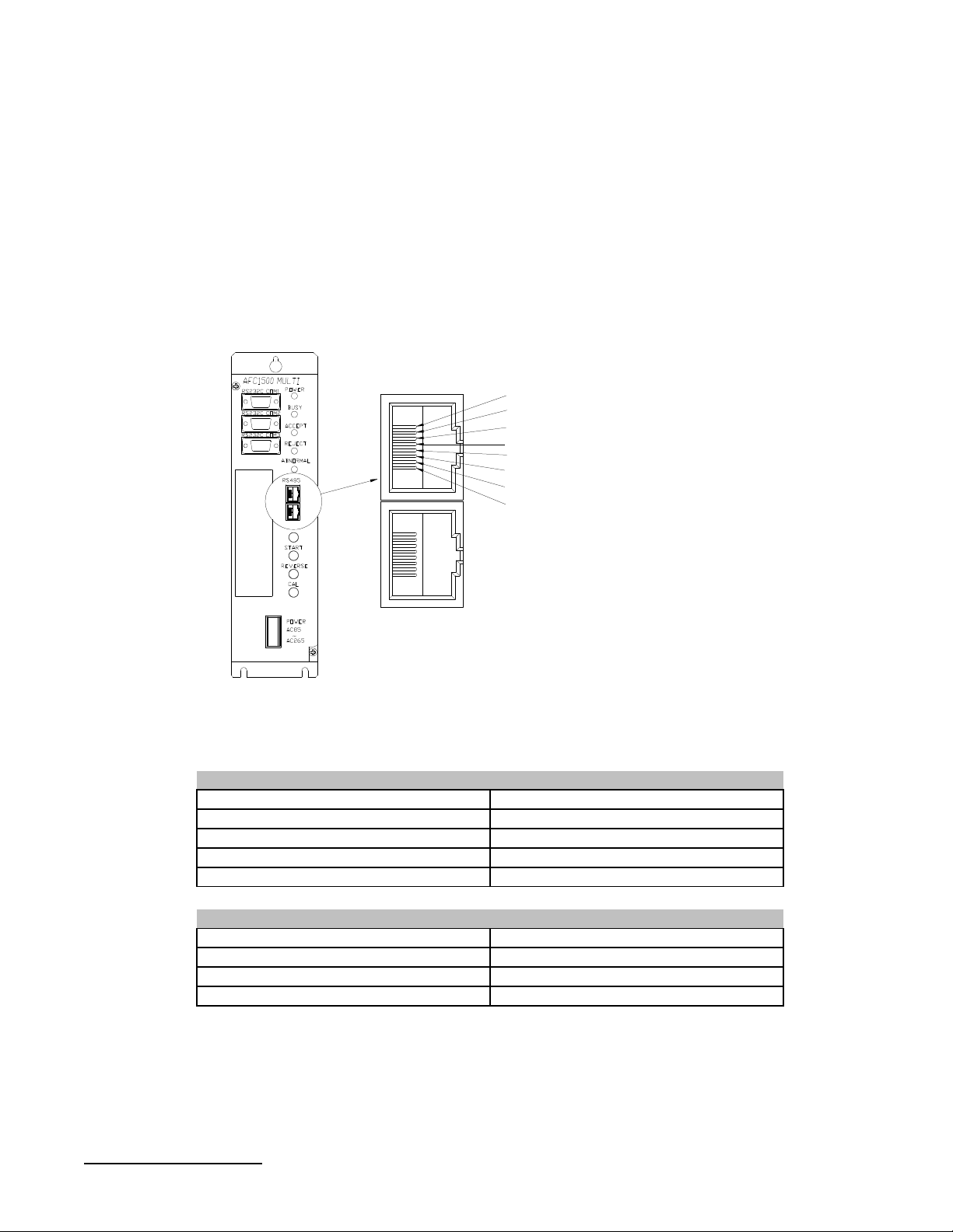
Description of Unit
Serial Port COM1
Serial Port COM2
Serial Port COM3
Interface board
Power on LED
Busy LED
Accept LED
Reject LED
Abnormal LED
RS485 port
Software EPROMs
Reset button
Start button
Reverse button
Calibration button
Power connector
Multi Unit Panel Description
Busy LED
Accept LED
Reject LED
Abnormal LED
Indicates when power is applied to the Multi Unit.Power On LED
Lights when the unit is performing a self check, reverse, fastening
operation or is downloading/uploading data to the AFC User Console
software package.
Lights if a fastening cycle or a self check test falls within acceptable
parameters. (This LED indicates status for ALL connected spindles)
Lights if a fastening cycle or a self check test is outside of acceptable
parameters. (This LED indicates status for ALL connected spindles)
Lights when a system abnormal condition is detected in the control
system of any connected spindles. (Does NOT indicate a fastening
reject). All operations are halted and cannot be restarted until the
Abnormal condition is corrected. Can be cleared only by the Reset
function. (see AFC1500 Fastening System Manual for Abnormal
Troubleshooting)
Chapter 1: Multi Unit Outline
13

Multi Unit Panel Description
RS485 Port
Reset Button
Start Button
Reverse Button
Cal Button
Power Connector
Interface Board (I/O)
Serial Port COM1
(Output)
Serial Port COM2
(Input)
RJ45 style connector used to connect to all AFC1500 Servo (SAN)
Units included in the system, and also the User Console. Two (2)
proprietary communication channels CH1 & CH2 are accessed using
this port.
Resets all signal and communication buffers to “clear” conditions.
Clears the Abnormal signal and performs the Torque Transducer Zero
Level Check.
Starts the fastening cycle. Requires a pulse of 0.1 to 0.5 sec. for
“Normal” start selection or must be maintained during complete cycle
for “Deadman” start selection.
Turns the spindles in the opposite direction of the preset fastening
direction while the button is held active.
Performs the Torque transducer shunt calibration test. When
depressed, the Servo (SAN) Units will display either a green accept
LED or red reject LED indicating status of the individual Calibration
test.
Connects to incoming power : 100 to 220VAC (auto-sensing), Single
phase, 50/60 Hz.
Allocation socket for input/output signal Interface boards. Options
available are Discrete I/O, Interbus-S, DeviceNet, Profibus, CClink, or
Allen Bradley Remote I/O (Rockwell License #199906006)
Communication port for fastening result data output to any external
device, i.e.: host computer, serial printer, Network Unit, etc. Data
output format is configured using the User Console (AFC) Software
package.
Communication port for ASCII data input from peripheral devices. (
ex. bar code readers, RF tag, etc.) Allows external ASCII data to be
merged with Fastening result data.
Reserved for external remote data DisplaySerial Port COM3
Chapter 1: Multi Unit Outline
14

Setup and Wiring
•
This chapter describes the Multi Unit mounting
requirements and all wiring connection
references including communication port
specifications.
In this chapter
§Installation
§Connection
Chapter 2: Setup and Wiring
15
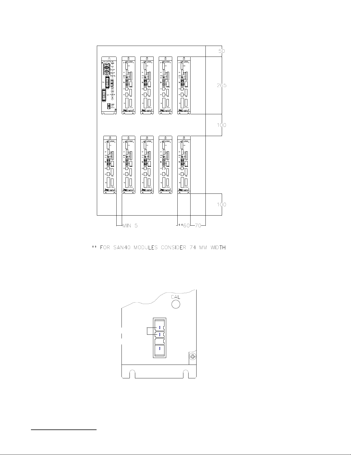
Multi Unit Installation
The Multi Unit should mounted into a NEMA12 / IP52 enclosure at a
minimum and spaced similar to the 1500 SAN Units (Shown Below).
Power Input
An auto sensing power supply allows for input power in the range of 100 - 220VAC
single phase, 50/60 hertz.
Chapter 2: Setup and Wiring
16
100 - 220 VAC ±15%
NOT CONNECTED
GROUND
POWER
AC100
~
AC220

Power wiring reference
Even though the Multi Unit power input allows it to connect to 120 VAC- 220
VAC power lines, typically the unit is connected to the same power source
that the SAN Units are connected to. (200 to 220 VAC ± 10%) . In the
example wiring diagram shown below there are two power branches: one is
for the control circuitry connected to 120 VAC and the other is for the SAN
power circuitry, connected to 220 VAC. For convenience, the Multi Unit is
wired together with the AFC1500 Servo Controllers. Note that the Multi Unit
is using one phase while the Servo Controllers use three phases.
.
440VAC, 3PH
1
2
AFC1500
MULTI UNIT
3
Chapter 2: Setup and Wiring
17
Multi Unit connection
RS485 Communication Port
The Multi Unit uses an RS485 port to perform the communication operations
with both the AFC1500 Servo (SAN) Controllers and the AFC User Console
(computer). Two RJ45 connectors are provided. Both connectors are internally
jumpered in parallel. Each port has two channels CH1 and CH2. CH1 is
dedicated to handle the communication with the User Console, that is to say,
all preset data upload and download, fastening results monitoring and
collection.
Channel CH2 is a high speed connection to all AFC1500 Servo Controllers. It
controls all required commands to perform the fastening cycle.
8 GND
7 GND
6 TX- CH1
5 RX+ CH1
4 RX- CH1
3 TX+ CH1
2 TX/RX- CH2
1 TX/RX+ CH2
RS485 CH1 port specifications
RS485 CH2 port specifications
Chapter 2: Setup and Wiring
18
9600 OR 38,400 baudSpeed
Std Cat 5 EthernetCable
31Maximum number of connected devices
ProprietaryProtocol
RS485 StandardOperating Voltage
Up to 500K baudSpeed
Std Cat 5 EthernetCable
ProprietaryProtocol
RS485 StandardOperating Voltage
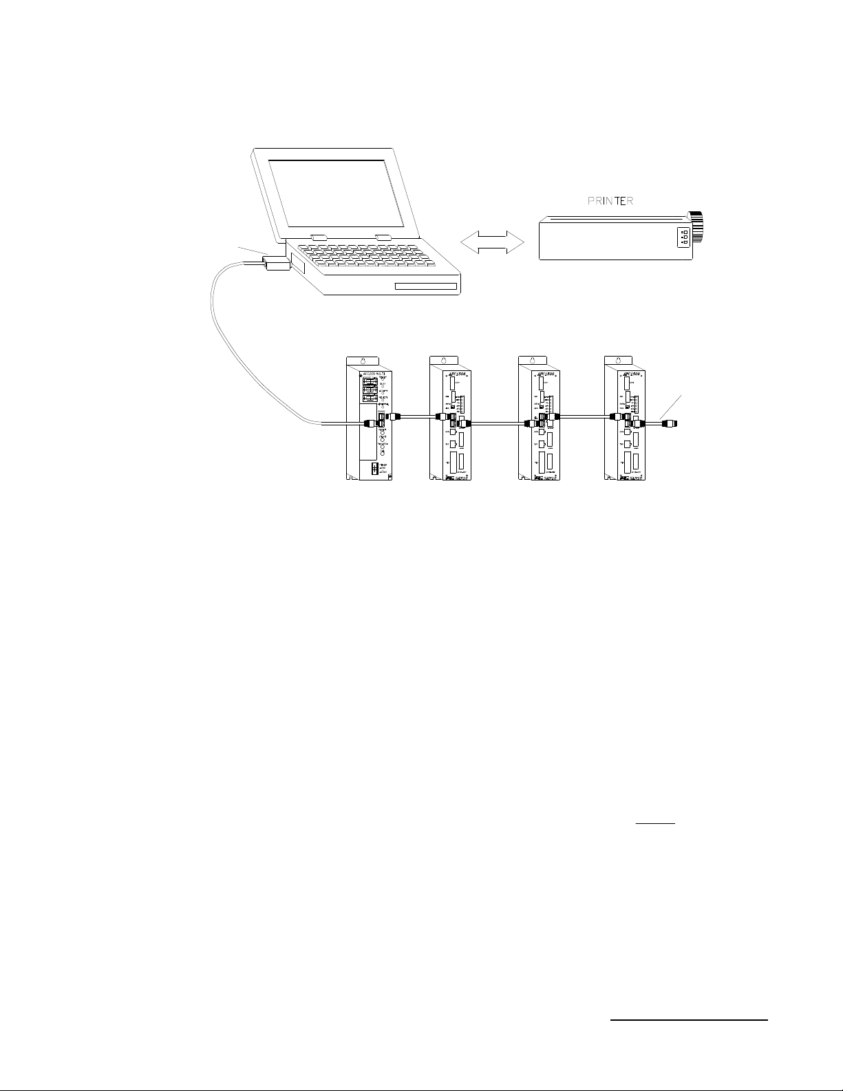
RS485 port connection
Converter
RS485/RS232
Cable FEB-1274
(Includes Converter )
Note: Many laptop computers have external RS232 serial ports which require
converters to change to RS485 to connect to the Multi Unit. When using a self
powered RS485/RS232 converter (Telebyte #253-PP2 www.telebyteusa.com),
communication errors may occur due to the loss of power during communication to
large numbers of spindles. In this case, use a powered converter or direct RS485
communication.
If your laptop does not have a RS232 card, it is recommended that a PCMCIA Serial
RS232 or RS485 card be used. (ie. www.socketcom.com)
We do not recommend USB RS232 converters. Many of these converters in the
market will not operate correctly using this system.
Multi Unit
AFC1500 Servo Controllers
1
2
Cable FEB-1268
UP TO 31 UNITS
3
Note: In order for the Multi Unit to communicate properly to the SAN (Servo) Units,
the spindle(s) address DIP Switch must be set correctly. No two units may share the
same address, however, unit addresses may be skipped or started from a number
besides #1. If units are skipped, the missing spindle addresses MUST be removed
from the programmed fastening sequence or an abnormal will result.
(See AFC1500 Operations Manual Section 4.10 for Address setting information)
Chapter 2: Setup and Wiring
19
 Loading...