

Page 1

MICRO E-HS-2.1
ELECTRIC SERVO MICRO NUTRUNNER
OPERATION INSTRUCTION MANUAL
2nd Edition Rev.1 December 2012
FEC MICRO NR
Page 2

WARNING
All applicable national and local codes must be followed when installing and operating the
equipment detailed in this manual.
FAILURE TO ABIDE BY THESE CODES AND THE SPECIFICATIONS DESCRIBED IN
THIS MANUAL CAN RESULT IN SERIOUS INJURY TO PERSONNEL AND/OR DAMAGE
TO THE EQUIPMENT!
Any questions regarding the contents of this document or any related matter should be
directed to FEC INC. at (586) 580-2622, faxed to (586) 580-2620 or emailed to
The information set forth in the following document is the property of FEC INC.
This document shall not be released to or copied for any person and/or organization
With out the expressed prior consent of FEC INC.
Unauthorized reproduction or distribution of this manual is strictly prohibited.
Please contact FEC INC. if you require additional copies.
Page 3

Revision
date
Manual No.
Content of revision
2009/06/10
First Edition
Original manual release
2012/02
Second Edition
Revised per latest Japanese translations
2012/12
2.1
Added selection for X-Y curve in SD Memory
Chapter 4 pg 4-14 Chapter 7 pg 7-21, 7-27
Manual Numbering Convention
MICRO E-HS-1
DSP1500 = Servo Press
AFC1500 = Nutrunner
FUSION = DC Hand Tool
HS = SAN / MNR Unit Hardware
Operation Manual
HM = Multi / Main Unit Hardware
Operation Manual
HM-ENET = Ethernet Manual for
Multi / Main Unit
SW = Software Manual
DSP1500 = Servo Press
AFC1500 = Nutrunner
FUSION = DC Hand Tool
MICRO = Micro Nutrunner
E = English Version
S = Spanish Version
*Japanese Version furnished by DDK
uses DDK numbering convention.
Version Number
(Major Revision Level)
Revision History
Page 4

For the safety of operator and equipment
Please confirm the followings when unpacking this equipment:
◆ Ensure that you received the correct model, as ordered.
◆ Ensure that there are no missing parts.
◆ Check for any damage caused during transportation.
Points to check when unpacking
◆ It is important for you to read all “Safety Precautions” before using the equipment, and
understand and observe all instructions and recommendations included in this manual.
◆ Read all instructions and recommendations included in this manual, understand the functions
and performance of this nutrunner, and correctly use this machine.
◆ Wirings and parameter settings shall only be conducted by a qualified professional.
◆ Never conduct a withstand voltage test or insulation resistance test on this equipment.
◆ Indicate the following on all instruction manuals that use this equipment:
”This equipment is capable of voltages hazardous to human life.”
Introduction
Thank you for purchasing our Electric Micro Nutrunner System.
This instruction manual describes the procedures for installation, wiring, and handling, and
actions to be taken in case of any failure.
◆ This instruction manual shall be delivered to the end user who operates the equipment.
◆ Read all instructions before use, and always keep this instruction manual with the equipment.
◆ Items not described in this instruction manual shall be considered “unavailable”.
◆ The product specification and appearance described in this instruction manual is subject to
change without notice.
◆ All rights reserved. Any disclosure, copying, distribution, or use of the information contained
herein for other than its intended purpose, is strictly prohibited.
Page 5

Warranty Period
The standard warranty period is one year from the date of purchase or one year from delivery to
the designated End User (not to exceed 18 Months). Actual terms are order specific.
Provision of warranty
If your product proves to be defective, although it has been used properly in accordance with
this instruction manual, during the period of warranty, this product will be repaired free of
charge.
However, in the following cases, the customer will be required to pay for repair charges, even
for defects occurring within the warranty period.
1. Any defect due to improper conditions, improper circumstances, and improper handling.
2. Any defect due to modifications or repairs performed by the customer.
3. Any defect caused by other equipment.
4. Any defect caused by customer failing to meet the equipment’s specification.
5. Any defect due to natural disasters and accidents.
This warranty shall be limited to repairing or replacing this product. Any liability for indirect or
consequential loss or damage of any kind incurred or suffered by the customer due to a defect
of the product is excluded.
Warranty
Introduction
Page 6

Warning
Caution
This symbol indicates that failure to observe instruction marked
with this symbol may result in severe personal injury or death.
This symbol indicates that failure to observe instruction marked
with this symbol may result in minor personal injury or material
damage.
Caution
Warning:
Fire
Caution:
Electric shock
Ground
Prohibited
Do not disassemble
Required
Warning:
Electric shock
Caution:
Fire
Safety Precautions
Caution:
High Temperature
Read all instructions before operating the equipment in order to use this equipment safely and correctly.
Prior to use, read this instruction manual carefully and fully understand the equipments functions, safety
precautions and instructions. Safety precautions in this manual are marked with two symbols [Warning]
and [Caution].
To prevent danger to the user and other persons as well as property damage, instructions that must be
fully observed are marked with the symbols below.
◆ This instruction manual uses the following two symbols according to the degree of damage that
may be caused when the instruction is not observed.
Even instructions that are marked with may result in severe damage if they are not
observed according to conditions.
Contents marked with the above symbols are very important instructions. For your safety, follow all
instructions and especially those marked with these symbols.
◆ This instruction manual uses the following additional symbols for instructions that shall be
observed.
Page 7
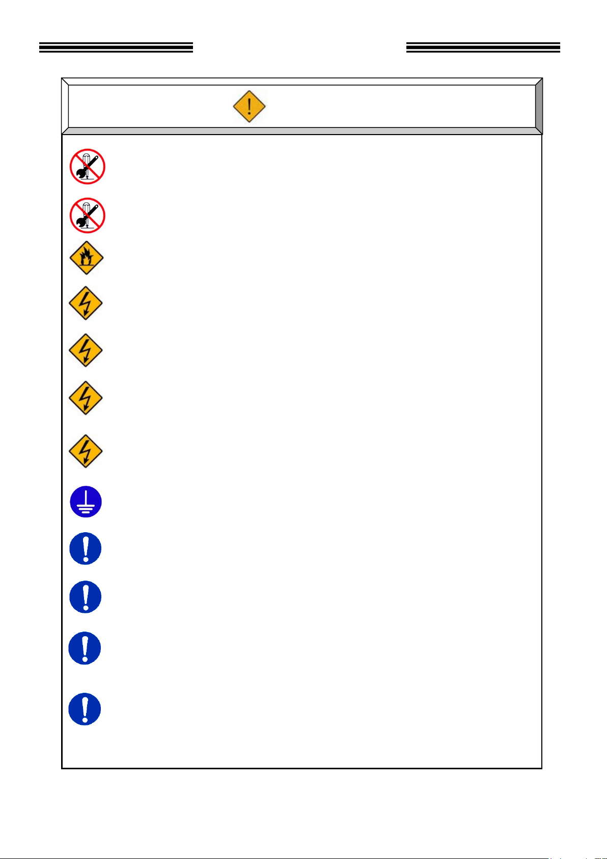
Do not remove the motors and gear cases of tools while power is applied..
The tool output spindle may rotate and cause injury.
Do not repair, disassemble, or modify the equipment individual components of the system.
Failure to observe this instruction may cause injury, electric shock, fire, and malfunction.
Never operate the equipment where it is exposed to water, near a corrosive atmosphere or
flammable gases. Failure to observe this instruction may cause fire.
Keep fingers away from the connectors while the equipment is turned ON and for a while after
the equipment is turned OFF. Failure to observe this instruction may cause electric shock.
Wiring operation and maintenance work shall be conducted by a qualified professional.
Failure to observe this instruction may cause electric shock and injury.
Turn OFF the power when conducting wiring operation and maintenance.
Failure to observe this instruction may cause electric shock and injury.
Never damage the cables, apply excess stress to cables, or squeeze the cables.
Never use damaged cables. Failure to observe this instruction may cause electric shock and
fire.
Conduct type-3 grounding of FG terminals.
Failure to observe this instruction may cause electric shock.
In case of an abnormal odor, noise, or operation error occurrence, stop operation immediately
and turn OFF the power source. Failure to observe this instruction may cause injury and fire.
Install a Power shutdown device in order to ensure the safety of equipment.
Failure to observe this instruction may cause injury.
Install an emergency stop circuit on the outside of equipment in order to stop operation
promptly. Failure to observe this instruction may cause injury.
Keep away from the equipment during recovery from a temporary blackout, and ensure safety
measures are conducted after restarting the equipment. The equipment may suddenly restart.
Failure to observe this instruction may cause injury.
Warning
Safety Precautions
Page 8
Transport the equipment properly according to its weight.
Failure to observe this instruction may cause injury and malfunction.
The conditions when transporting the equipment by ship is as below.
◆Ambient temperature: -5°C~+55°C (Avoid freezing)
◆Ambient humidity: 50% RH or lower (Avoid moisture)
◆Package: Tight seal
◆Rust prevention measure: Keep dry and ship with humidity control devices (desiccant).
Failure to observe this instruction may cause earth leakage and malfunction.
Do not hold cables and output spindles when transporting the tools.
Failure to observe this instruction may cause injury and malfunction.
Do not hold the indictor on the front panel when transporting the controller Unit.
The indicator may come off and drop from the front panel.
Failure to observe this instruction may cause injury and malfunction.
The equipment shall be stored under the following conditions.
◆Ambient temperature: -5°C~+55°C (Avoid freezing)
◆Ambient humidity: 90% RH or lower (Avoid moisture)
◆Atmosphere: Indoors (Avoid direct sunlight)
No corrosive gases or flammable gases
No oil mist, dust, water, salt, iron powder
◆Avoid direct vibration or shocks
Failure to observe this instruction may cause earth leakage and malfunction.
Caution
Transportation / Storage
Safety Precautions
Page 9
Install all tools firmly where they can bear the maximum torque during operation.
Failure to observe this instruction may cause injury and malfunction.
Install the controller Unit firmly inside the control panel using the specified screws.
Failure to observe this instruction may cause malfunction.
Use the specified tool for the controller Unit.
Failure to observe this instruction may cause fire and malfunction.
The controller Unit shall maintain the specified distance from other devices.
Failure to observe this instruction may cause fire and malfunction.
Do not block the ventilation holes of the controller Unit.
Avoid any foreign body from entering inside the equipment.
Failure to observe this instruction may cause fire and malfunction.
The power source shall be provided with safety measures such as breakers and
circuit protectors. Failure to observe this instruction may cause fire and malfunction.
Do not use tools or controller Units that are damaged or missing parts.
Failure to observe this instruction may cause fire, injury, and malfunction.
Do not get on the top of equipment or do not place heavy objects on the top of equipment.
Failure to observe this instruction may cause injury, and malfunction.
Do not subject the equipment to excess shock and impact.
Failure to observe this instruction may cause malfunction.
Conduct wirings properly and firmly.
Failure to observe this instruction may cause injury, false operation, and malfunction.
Operate the equipment within the specified power supply voltage.
Failure to observe this instruction may cause injury, electric shock, fire, and malfunction.
When operating the equipment in the following conditions, take sufficient measures
to shield the equipment.
◆Location where electrical noise is generated
◆Location where the equipment is subjected to a strong electric field or magnetic field
◆Location near a high power wire.
Failure to observe this instruction may cause injury, false operation, and malfunction.
Caution
Safety Precautions
Installation / Wiring
Page 10

Never operate the equipment with wet hands.
Failure to observe this instruction may cause electric shock.
Use the equipment under the following conditions.
◆Ambient temperature: 0°C~+45°C (Avoid freezing)
◆Ambient humidity: 90% RH or lower (Avoid moisture)
◆Atmosphere: Indoors (Avoid direct sunlight)
No corrosive gases or flammable gases
No oil mist, dust, water, salt, iron powder
◆Avoid direct vibration or shocks
Failure to observe this instruction may cause earth leakage and malfunction.
Confirm and adjust all parameters before operation in order to prevent unexpected
movement of the equipment.
Failure to observe this instruction may cause injury, false operation and malfunction.
Never conduct extreme adjustments or setting changes that may cause instability of operation.
Failure to observe this instruction may cause injury, false operation and malfunction.
The equipment may restart suddenly when the equipment is reset with the start signal ON.
Always ensure that the start signal is OFF before resetting the equipment.
Failure to observe this instruction may cause injury.
Do not turn ON and OFF the equipment repeatedly.
Failure to observe this instruction may cause malfunction.
Do not use the equipment at torque higher than the maximum torque.
Failure to observe this instruction may shorten equipment life or cause malfunction
due to the high temperature caused by overload.
In case any abnormality occurs, remove the cause and ensure safety before resetting
and restarting the equipment.
Failure to observe this instruction may cause injury.
Caution
Safety Precautions
Operation / Adjustment
Page 11

Page
Chapter 1: Outline
1-1
1.1 About This operations manual
1-2
1.2 Features
1-3
1.3 Functions
1-5
1.4 System requirements
1-7
Chapter 2: Specifications
2-1
2.1 Main Specifications
2-2
2.2 Duty Cycle Calculation
2-3
2.3 SAN Unit Specifications
2-4
2.4 Capability.
2-5
2.4.1 Nutrunner Tool Specification Table
2-6
Chapter 3: System Description
3-1
3.1 System Block Diagram
3-2
3.1.1 System Block Diagram Description
3-2
3.2 Micro-NR MNR UNIT Front panel
3-3
3.2.1 MNR Front Panel Switches and Connectors
3-3
3.2.2 MNR Status LED
3-4
3.3 Micro-Nr Keyboard-Display description
3-5
3.3.1 MNR Serial Pin out
3-5
3.3.2 MNR Communication Protocol
3-6
3.3.3 MNR Communication Format
3-6
3.3.4 MNR Communication Format Description
3-7
3.3.5 Cable Connection to MNR Unit
3-8
3.4 Micro-NR (Tool) Unit
3-9
Chapter 4: System Setup and Wiring
4-1
4.1 Component Dimensions
4-2
4.1.1 MNR Controller Unit Dimensions
4-2
4.1.2 Micro-NR Tool Dimensions
4-3
4.2 Power Requirements and Connections
4-4
4.2.1 MNR Unit
4-4
4.3 Wiring PLC I/O
4-6
4.3.1 Explanation of MNR Unit I/O
4-7
4.3.2 Work / Parameter Select Table
4-8
4.3.3 PLC Wiring Sample
4-9
4.4 Signal Timing Chart
4-11
4.5 USB Communication Port
4-12
4.6 MNR Unit DIP Switch setting.
4-13
4.6.1 MNR Unit DIP SW1 settings
4-14
4.7 Tool Connection (cabling)
4-15
4.7.1 Cable Installation Guidelines
4-16
4.7.2 Considerations for Cable Trolleys
4-17
4.7.3 Considerations for Flexible Cable Tracks
4-17
4.7.4 Considerations for Cable Trays and Ladders
4-17
4.12 Firmware Flash Connector (CN8).
4-36
Table of Contents
Page 12

Chapter 5: Power Up and Initial Checks
5-1
5.1 Before Powering On
5-2
5.2 Initial Data Setting
5-3
Chapter 6: Fastening Instructions
6-1
6.1 Fastening Control
6-2
6.1.1 Torque / Angle Method – Target Torque Control
6-2
6.1.2 Torque / Angle Method – Target Angle Control
6-4
6.2 Speed Functions
6-6
6.3 Reverse Functions
6-8
6.4 Special Functions
6-9
6.4.1 One Pulse Reverse Function
6-9
6.4.2 Rundown Revolution Limits
6-10
6.4.3 Torque Inhibit Function
6-11
Chapter 7: System Operations
7-1
7.1 MNR Display and Programming operation.
7-2
7.1.1 Manual Fastening controls for Display Programming Unit
7-2
7.1.2 Fastening Preset / Results Display
7-3
7.1.3 Fastening Presetting / Result Display Controls
7-3
7.2 Display Indication Modes.
7-4
7.2.1 Status Display
7-5
7.2.2 Real-time display indication mode.
7-8
7.2.3 Fastening results display mode.
7-10
7.2.4 Parameter display mode
7-11
7.2.5 Parameter Data List
7-13
7.3 Parameter Display, Select and Data Edit Operation
7-18
7.3.1 Parameter Select Mode
7-18
7.3.2 Data Edit Mode
7-19
7.3.3 Parameter Setup Confirmation
7-20
7.4 Torque Unit / RS232C / Memory Card Display Mode
7-21
7.4.1 Torque Unit Display / Edit Mode
7-22
7.4.2 RS232 Display / Edit Mode
7-23
7.4.3 Memory Card Station Name Display / Edit Mode
7-24
7.4.4 Memory Card Data Save Display / Edit Mode
7-25
7.4.5 Memory Card Data File Update by Size Display / Edit Mode
7-26
7.4.6 Memory Card Data File Update by Time Display / Edit Mode
7-27
7.4.6.1 Memory Card X-Y Curve Size Setup
7-27
7.4.7 Memory Card Abnormal Display / Edit Mode
7-28
7.4.8 Torque Unit / RS232C / Memory Card Data Update Confirmation
7-28
Chapter 8: Maintenance and Inspection
8-1
8.1 Inspection Items
8-2
8.1.1 Nutrunner (Tool)
8-2
8.1.2 Homerun cables
8-2
8.1.3 MNR Unit
8-3
8.1.4 Air Handling Units (Air Conditioner, Heat Exchanger, etc.)
8-3
8.2 Basic operational tests
8-4
8.2.1 Torque transducer.
8-4
8.2.2 Resolver.
8-4
8.3 Replacements
8-5
8.3.1 MNR Unit Replacement
8-5
8.3.2 Replace Nutrunner (tool)
8-6
8.3.3 Replace Homerun cables
8-6
Page 13

Chapter 9: Troubleshooting
9-1
9.1 Abnormal Conditions.
9-2
9.2 Torque Transducer Origin Error, Cal Check Error.
9-3
9.2.1 Code 1-0 Torque transducer / Zero Voltage error.
9-3
9.2.2 Code 1-1 Torque transducer / Cal Voltage error.
9-3
9.2.3 Code 1-2 Torque transducer / Zero check error.
9-3
9.2.4 Code 1-3 Torque transducer / Cal self-check error.
9-4
9.2.5 Code 1-4 Torque transducer / Started on Zero condition error.
9-4
9.2.6 Code 1-5 Torque transducer / Started on Cal condition error
9-4
9.2.7 Code 1-6 Torque transducer / Zero Level Self Check Error
9-4
9.3 Torque Over Abnormals
9-5
9.3.1 Code 2-1 Torque Over Abnormal / Torque Inhibit High Limit
9-5
9.4 Tool EEPROM Errors
9-6
9.4.1 Code 3-0 Preamplifier / Tool ID Checksum error
9-6
9.4.2 Code 3-1 Preamplifier / Tool type error
9-6
9.4.3 Code 3-2 Preamplifier / Started without tool connected
9-6
9.4.4 Code 3-3 Preamplifier / Tool is not connected
9-6
9.5 System Memory / Memory Card Errors
9-7
9.5.1 Code 4-1 system memory error / Flash ROM read error
9-7
9.5.2 Code 4-3 system memory card error / Card write error
9-7
9.6 Servo Amplifier Response / Resolver
9-8
9.6.1 Code 5-0 Servo Amplifier reply error / No reply from Resolver
9-8
9.7 Servo Type Error
9-9
9.7.1 Code 6-0 Servo Type error / Servo Type mismatch
9-9
9.8 Servo Amplifier Error
9-10
9.8.1 Code 8-1 Servo Amplifier error / Servo is over heated
9-10
9.8.2 Code 8-4 Servo Amplifier error / Over current
9-10
9.8.3 Code 8-5 Servo Amplifier error /Internal power supply
9-10
9.8.4 Code 8-6 Servo Amplifier error / Input Voltage abnormal
9-11
9.8.5 Code 8-9 Servo Amplifier error / Over speed.
9-11
9.8.6 Code 8-10 Servo Amplifier error / over load ( I square T)
9-11
9.8.7 Code 8-11 Servo Amplifier error / Resolver Signal Error
9-11
9.8.8 Code 8-12 Servo Amplifier error / Amplifier Parameter Error
9-12
9.8.9 Code 8-13 Servo Amplifier error / Amplifier Program Error
9-12
9.8.10 Code 8-15 Servo Amplifier error / PDU Error
9-12
9.8.11 Code 8-16 Servo Amplifier error / CPU Error
9-12
9.9 Parameter Error
9-13
9.9.1 Code 9-0 Parameter Error / Missing speed preset.
9-13
9.9.2 Code 9-1 Parameter Error/ Missing Speed or Time
9-13
9.9.3 Code 9-2 Parameter Error/ Parameter Select Error
9-13
9.9.4 Code 9-3 Parameter Error/ Missing Reverse Speed
9-13
9.9.5 Code 9-4 Parameter Error/ Torque Speed not set
9-13
9.9.6 Code 9-5 Parameter Error/ Torque Setup Error
9-14
9.9.7 Code 9-6 Parameter Error/ Angle Setup Error
9-14
9.9.8 Code 9-7 Parameter Error/ Reverse Torque over.
9-14
9.10 Micro-NR MNR Unit Fastening Faults and Causes
9-15
9.10.1 Accept Conditions
9-15
9.10.2 Reject Conditions
9-15
Page 14

Page 15

FEC Micro Nutrunner Operations Manual Chapter 1: Outline (Rev. 2: 02/12)
Chapter 1: Outline
Page 1-1
Page 16

Chapter 1: Outline
Chapter
Item
Contents
1.1 About This operations manual
This manual details the configuration, components, specifications, and the operation of the MNR-
8 Micro Nutrunner Fastening System.
The following table outlines the contents of each chapter:
Chapter 1 Outline Basic characteristics and requirements of the MICRO
Chapter 2 Specifications General specifications of the MICRO NUTRUNNER
Chapter 3 System Description Description of standard and optional system
Chapter 4 System Setup and Wiring Equipment installation procedure, dimensions, Input
Chapter 5 Power Up and Initial Checks Preliminary power on and operational tests.
Chapter 6 Fastening Instructions Basic fastening operations and presetting procedures.
Chapter 7 System Operations Instructions for the input of preset data and monitoring
Chapter 8 Maintenance and Inspection Guide for preventive maintenance.
Chapter 9 Troubleshooting Descriptions of fastening rejects, abnormal operation
Appendix A Reference Drawings Electrical reference drawings of standard cables and
NUTRUNNER System.
System.
components.
and Output signal descriptions and requirements for
PLC programming.
explanations.
faults, and corrective actions.
connections.
Page 1-2
Page 17

FEC Micro Nutrunner Operations Manual Chapter 1: Outline (Rev. 2: 02/12)
1.2 Features
{ The MICRO NR Fastening System is a culmination of over thirty years of electric fastening
expertise integrated with the latest miniature electronic technology. For small screw
applications
(M2 – M3), the MICRO NR provides a highly accurate, transducerized fastening system with
fully programmable set-up. The system is designed with modular construction in mind keeping
maintenance and spare parts to a minimum.
{ The basic elements of this system are:
1) A brushless, Resolver Based permanent magnet high speed motor
2) Reliable intelligent Torque Transducer
3) A combination Fastening Controller / Digital Servo Amplifier (MNR unit)
{{{{ Compact Design
As the result of miniaturization circuit technology, the compact MNR units (Controller)
maintain a size not much bigger than a standard letter envelope in spite of the built-in power
source and Servo Amplifier. The MNR Unit can be back / side panel mounted.
{{{{ Front Keypad-Display.
A front keypad display is used for programming preset parameters and/or monitoring the
fastening results and status conditions in the system.
{{{{ Multiple Condition Display
The system features a multi-colored LED that lights to indicate the status of the System.
{{{{ Parameter Selection
Totally digitized system eliminates analog potentiometers.
Up to 8 different sets of parameters can be stored into Flash ROM for each spindle.
No battery-backup of memory is required.
{{{{ Motor
A high speed, permanent magnet DC motor provides for improved fastening control. The
sealed design of the motor provides greater protection from contamination without generating
excess heat. The resolver is uniquely designed to withstand harsh environments and provide
high resolution control / angular feedback signals.
{{{{ Preamplifier
Quality control of the tool torque transducer is accomplished electronically (digitally) through
the EEPROM (Electrically Erasable Programmable Read Only Memory) in the preamplifier.
During factory setup of the torque transducer, the unit is Dead Weight and dynamically tested
against Standards that are certified and traceable to the National Institute of Standards and
Technology. The resultant data is then programmed into the preamplifier where it is stored
on non volatile EEPROM.
{{{{ Servo Amplifier (Servo Drive)
Reduced equipment size with improved drive circuit strength is the result of incorporating
Insulated Gate Bipolar Transistor (IGBT) technology into the drive System.
{ Motor, Resolver and Torque Transducer Combined Single Cable
A combined cable reduces the number of cables in the system and provides easier cable
management
Page 1-3
Page 18

Chapter 1: Outline
1.3 Functions
{{{{ Fastening function.
The following fastening control methods can be selected for either clockwise (CW) or
counterclockwise (CCW) operation:
P Torque / Angle Control
The fastening control method of the system is a combination of both Torque Control and
Angle Control. Setting both a torque target torque and an angle target torque allows the
system to target whichever setting would be reached first. The system can be also set-up to
run either of the fastening methods individually by setting the undesired target limit above it’s
respective high limit value.
{{{{ Multiple speed control
Four separate speed settings can be set allowing precise speed control for high accuracy
control. One reverse speed can also be set-up.
{{{{ Reject / Abnormal Condition Display
When a fastening Reject has occurred, the tool stops, outputs the appropriate signal and
displays the resultant data in the Detachable Keypad-Display unit if it is connected. Upon a
fastening reject, the unit will not require resetting prior to the next cycle.
The System will output an Abnormal signal when it detects there is a problem (Zero Check
out of limits, incorrect component connection, etc.) within the system itself. The output will be
displayed as a code on the affected Axis unit. Refer to Chapter 9 Troubleshooting for more
details. Correction of the abnormal cause and reset of the system is required on an abnormal
before normal operation can resume.
{{{{ Torque Inhibit Function
The Torque Inhibit function allows the controller to ignore the torque seen during initial startup for a programmed period of time. This is especially useful in self-tapping applications
where initial cutting of threads can require higher torque that the final target torque settings.
{{{{ Tool Type Check Function
The MICRO NR tools have an EEPROM in the preamplifier that contains tool data specific for
each tool. The Tool type check function reads the information of the tool EEPROM and
compares it to the information of the MNR Controller; any mismatch is reported as a Tool
Type Error Abnormal.
The tool type check is performed during the following times:
1) When the equipment is powered on.
2) When preset data is downloaded from a user console to the Axis unit.
3) When a tool is changed.
Page 1-4
Page 19

FEC Micro Nutrunner Operations Manual Chapter 1: Outline (Rev. 2: 02/12)
1.4 System requirements
To ensure the most effective and extended use of all equipment, adhere to the following
specifications:
{{{{ Tool Installation
Tools must be installed in the proper positions and with adequate bolts. Use the supplied
bolts to prevent the tool from loosening due to vibration. A minimum of 2mm of clearance is
required between tools, with nothing touching a mounted tool that will impact free movement
for torque reaction (or improper torque readings will result). The tool assembly contains
precision parts and electronic components, and must not be subject to excessive shocks or
stresses.
Keep in mind that the torque transducer is a strain gage based instrument and, although it
has been designed to withstand sudden shock, repeated shock (over time) could damage the
transducer. Therefore, cylinder cushions or shock absorbers should be used to decelerate
spindle slides and prevent excessive (hard stop) vibration, particularly in short cycle time
applications operating at high speeds.
{{{{ Fastening Operation
Avoid fastening beyond the full scale torque. Do not use a duty cycle (the ratio of the tool
rotating time to the machine cycle time) higher than 60%, even when the torque is below the
full scale value.
{{{{ Cable Wiring
P Use the specified cables for all System connections.
P Circuit breakers or fuses are required on branch circuit power feeds to the controllers.
P Do not use a high voltage circuit as a frame ground (FG). Also, the frame ground should
be separate from the power ground.
P When multiple MNR Controller units are used, ensure that each unit is connected to its
matching numbered tool, and that all connectors are locked.
P I/O cables must be run separate from any high voltage power sources or cabling, and must
not exceed 50 feet in length.
{{{{ Control Equipment (MNR units) Installation Environment
P Controllers should be located in a NEMA 12 enclosure.
P Controller units must be located a minimum of 600 mm from high transient voltage sources
such as transformers, motor starters, AC inverters and AC contactors. If it cannot be
avoided, the units must be properly shielded.
Do not use at the following locations.
P Areas under direct sunlight.
P Areas where the environmental temperature is out of the 32 °~122° F range.
P Areas where the relative humidity is above the 90% range.
P Areas where the temperature changes quickly, which may cause moisture.
P Areas where conductive powder, oil mist, saline, or organic solvents exist.
P Areas that have corrosive or combustible gases.
P Areas that have strong electric or magnetic fields.
P Areas where a strong vibration or shock could be transmitted directly to a Controller unit or
tool.
Page 1-5
Page 20

Chapter 1: Outline
{{{{ Static Electricity
MICRO NR System construction incorporates many electronic Surface Mounted Devices.
(SMD) It is advisable to strictly adhere to practices for safe electrostatic discharge in order to
prevent damage to the System when handling the units.
{{{{ Cleaning
Do not use any organic solvents, such as thinner, to clean an MNR unit or a tool. The solvent
could melt the surface paint, or penetrate inside and cause damage. A cloth dampened with
alcohol or warm water should be used to lightly wipe the components.
{{{{ Handling and Shipping
It is critical that MICRO NR System components are properly handled and shipped in order to
maintain the System's integrity. Adhere to the following requirements for shipping and
handling:
P Loose MICRO NR System components must be individually packaged in an approved anti-
static container or wrap to prevent damage from electrostatic discharge.
P Tighten mounting screws on all back panel mounted fastening controllers.
P Use care to wrap components to protect from moisture exposure during shipping
P All non-painted / coated metal parts (except for the tool motor and connectors) must be
greased or oiled to prevent rust.
P Adhere to Chapter 2 Specifications for environmental requirements.
Page 1-6
Page 21

FEC Micro Nutrunner Operations Manual Chapter 2: Specifications (Rev. 2: 02/12)
Chapter 2: Specifications
Page 2-1
Page 22

Chapter 2: Specifications
2.1 Main Specifications
{{{{ Power Supply Voltage
P 100~240 VAC, Single Phase, 50/60 Hz (24VDC Output)
{{{{ Operating Power Requirements
PPPP 180Watt
{{{{ Installation Requirement
P NEMA 12 enclosure (minimum).
{{{{ Range of Operation
P Duty cycle below 60% (reference Section 2.2 Duty Cycle Calculation)
{ Operating Conditions (may be met by incorporating an Air Handling Unit into System)
P Temperature: 0° ~ 50°C (32° ~ 122°F) Humidity: 20% ~ 90%, no moisture
{{{{ Storage Conditions
P Temperature: -5° ~ 55°C (23° ~ 131°F) Humidity: Below 90%, no moisture
{{{{ Shipping Conditions
P Temperature: -5° ~ 55°C (23° ~ 131°F) Humidity: Below 90%, no moisture
2.2 Duty Cycle Calculation
Duty Cycle is rated as a percentage of the time the motor is running to the time the motor is idle.
This is an important factor in determining overload protection for Servo Amplifiers and motors as
it directly relates to the amount of power or heat dissipation of the motor / servo package. The
rated duty cycle for the Micro NR System is calculated as follows:
Tool Rotation Time
Total Cycle Time (Tool Rotation + Tool Waiting)
Example: Tool Rotation Time = 3 Seconds x 100 = 25% Duty Cycle Percentage
Total Cycle Time = 12 Seconds
As a general rule, duty cycle, should not exceed 60%. IF duty cycles remain above 60% for extended periods, a Servo Amplifier Error / Overload will result (See abnormal CODE 8 -10). Protection for high duty cycle is a standard feature of the Servo Amplifier to prevent servo or motor
damage.
X 100 = Duty Cycle Percentage (%)
Page 2-2
Page 23

FEC Micro Nutrunner Operations Manual Chapter 2: Specifications (Rev. 2: 02/12)
2.3 MNR Unit Specifications
UNIT TYPE UAN-8
TOOL MOTOR TYPE MFT-080M10
TOOL MAX. TORQUE
TOOL MAX. SPEED 1100RPM
OVERALL TOOL WEIGHT 605gram
MNR INPUT POWER SUPPLY
MNR UNIT WEIGHT
100 – 240VAC Single Phase 150watt max.
0.8 Nm
(7.08 in lb))
24VDC Output
556g
{ Parameter / Firmware Storage: Flash ROM
{ Fastening Method: Torque / Angle
{ Data Communications: RS232C for MNR User Console Software or Data Output
USB for MNR User Console Software (See 7.4.2)
2.4 Capability
{{{{ Fastening Accuracy (Torque):
From 1/4 to full scale torque: 3 sigma scatter less than 5% of target torque.
{{{{ Torque Display Resolution: 4-digit display with floating decimal point
(In display unit)
{{{{ Angle Display Resolution: 1 degree.
Forward Max. count 9999 degree
Reverse Max. count 1999 degree
{ Torque transducer accuracy: (0 - Full Scale) ±1.5%
{ Linearity of torque transducer: ± 0.5% of Full Scale value (Maximum).
Page 2-3
Page 24

Chapter 2: Specifications
2.4.1 Micro Tool Specification Table
TOOL TYPE
MFT-080M10 MNR-8 0.8 0.08 8.0 .59 7.08 1100 1
CONVERSION GUIDE: 1 KGM = 100 KGCM = 9.8 NM = 7.2 FTLB = 86.7 INLB
Tool Assembly Model Number Breakdown
Example: MFT-080M10
MFT: MICRO NR Series Tool
080: .08 Kgm tool capacity (last digit indicates decimal position from left)
M10: Micro Resolver Motor (Model 10)
The tool lists located throughout this manual identify the specifications for the
standard Micro NR tool used with the MICRO NR System. If additional capacity,
information or special needs are required, please contact FEC INC.
SERVO
TYPE
NM KGM KGCM FTLB INLB MAX MIN
FULL SCALE TORQUE
SPEED
RPM
Page 2-4
Page 25

FEC Micro Nutrunner Operations Manual Chapter 3: System Description (Rev 2: 02/12)
Chapter 3: System Description
Page 3-1
Page 26

Chapter 3: System Description
Serial Output (1
) Ports
3.1 System Block Diagram
3.1.1 System Block Diagram Description
{ Spindle programming / monitoring is accomplished through either a detachable Laptop PC or
an embedded HMI PC, running the MNR User Console software package.
{ A keypad/display on each MNR Unit can be used to monitor the individual spindle status.
{ Discrete 24 VDC (Sinking or Sourcing) I/O on the MNR unit provides direct communications
with the PLC for limited individual spindle control.
User Console
Detachable Laptop
OR
Discrete
PLC I/O.
User Console HMI
Embedded
Serial Printer
Misc. Serial Device
Page 3-2
Page 27
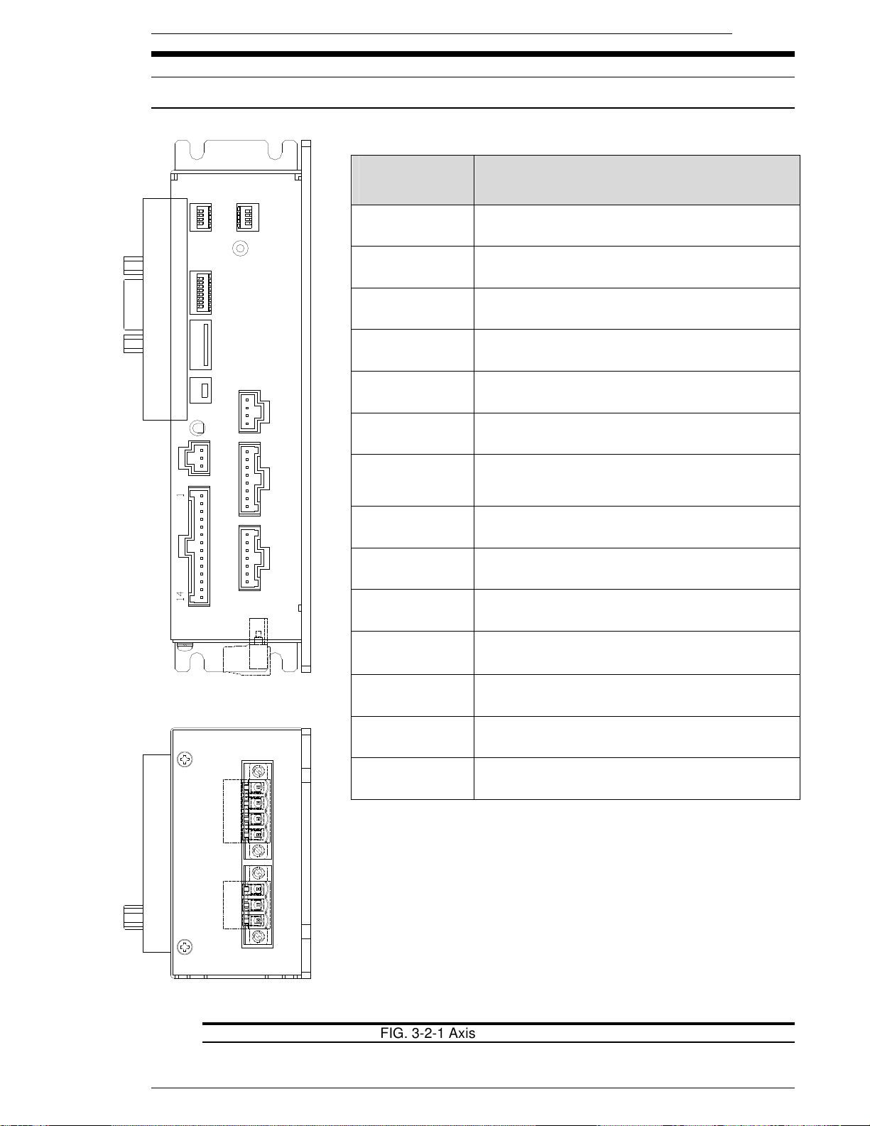
FEC Micro Nutrunner Operations Manual Chapter 3: System Description (Rev 2: 02/12)
ITEM AS
DESCRIPTION
3.2 MNR UNIT Front panel
3.2.1 MNR Front Panel Switches and Connectors
MARKED ON
UNIT
SW2
SW1
MEMORY
CARD
SW3
CN1
CN1
CN2
SW1
SW2
Amplifier programming port (Not Used)
Expansion Connector (Not currently used)
Sets Start signal type, Angle count type & display
Not Used – (Set all OFF)
USB
STATUS
CN2
MON
T/D
SW3
RESOLVER
MON.
Not Used – (Set all OFF)
Resolver connection for tool Motor / Resolver
cable. (Angle of Rotation input)
Monitor Output
Torque Analog Voltage and Angle Pulse Output
for connection to independent monitor device.
RESOLVER
PLC
T/D
MOTOR
PLC
MEMORY
CARD
USB
STATUS
POWER
Connection for tool Transducer cable.
(Torque signal input)
Motor Connection for tool Motor/Resolver cable.
(Motor Drive)
Connection for Inputs and Output (I/O) signals. .
Expanded memory for data storage and X-Y
Curve storage
Communication port for Computer Software
connection
Status LED (See 3.2.2 for more info)
Connection for Input Power.
24VDC 5A
MOTOR
1 2 3 4
U V W FG
1 2 3
POWER
MP CP 0V
FIG. 3-2-1 Axis unit Front panel controls
Page 3-3
Page 28
Chapter 3: System Description
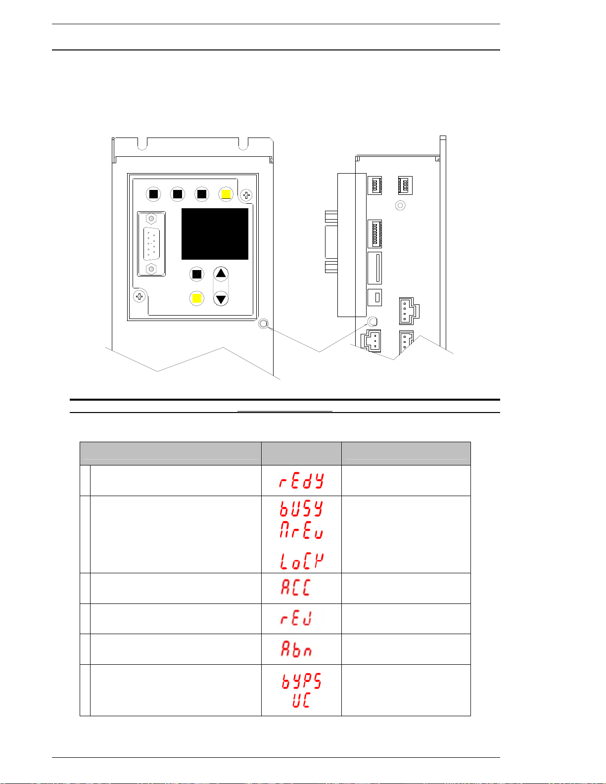
3.2.2 MNR Status LED
Located on the front of each MNR Unit is a status indicator LED which allows viewing from either
the front panel or from the side panel below the Keyboard / Display unit. Multiple system status
modes are displayed from this “shared status” LED.
START
RS232C
SAN3-DP2
REV.
CAL RESET
DATA
PARM. D-NO.
MODE
SET
DATA
STATUS
Fig. 3-2-2 Status LED
SHARED
STATUS LED
SW2
SW1
MEMORY
CARD
USB
STATUS
CN2
SW3
CN1
MON
1 READY
2
3 ACCEPT
4 REJECT
5 ABNORMAL
6
STATUS
BUSY
MANUAL REVERSE
SET-UP MODE
SERVO LOCK MODE
USER SOFTWARE BYPASS
USER SOFTWARE DOWNLOADING
SAN KEYPAD
LED DISPLAY
STATUS LED
ORANGE (ON)
ORANGE (FLASHING)
GREEN (ON)
RED (ON)
RED (ON)
RED (FLASHING)
Page 3-4
Page 29

FEC Micro Nutrunner Operations Manual Chapter 3: System Description (Rev 2: 02/12)
3.3 MNR Keyboard-Display unit description
The display unit incorporates programming and monitor functions display into the MNR controller.
It comes standard within the MNR unit. Programming of parameters can be accomplished using
the programming keys as well as displaying the fastening result data from the LED display. The
included RS232 9 pin connector allows User Console communication or the output of fastening
data to host or monitor systems.
NOTE: Refer to Chapter 7 for detailed operation using the keyboard/display unit.
START
REV.
CAL RESET
MODE
RS232C
SET
SAN3-DP2
3.3.1 RS232C Serial Pin out
Connector: DB-9P (Male)
Mating Connector: DB-9S (Female)
PIN SIGNAL DESCRIPTION
1 NOT USED
2 RXD NOT USED
3 TXD TRANSMIT DATA
4 DTR DATA TERMINAL READY (ALWAYS ON)
5 GND SIGNAL GROUND
6 DSR NOT USED
7 RTS REQUEST TO SEND (ALWAYS ON)
8 CTS CLEAR TO SEND
9 NOT USED
DATA
PARM.
D-NO.
DATA
Note: The CTS signal needs to be activated in order for the fastening data to be output. If it is
not activated, up to 16KB of data will be stored in the output buffer. Once the buffer is full, the
data will be overwritten in a First In, First Out (FIFO) process. The CTS signal may be connected to the RTS signal if data is to be “dumped” at every fastening.
Page 3-5
Page 30

Chapter 3: System Description
TQ
TQ
ASCII
49
ASCII
3.3.2 RS232C Communication Protocol
Communication protocol from the RS232C port is as follows;
Speed: 38400bps
Parity: NONE
Data Bits: 8 Bit
Stop Bit: 2 Bit
3.3.3 Front Display RS232C Communication Format
The data output from the RS232C port is a formatted ASCII output. This can be connected to a
serial printer, computer or other peripheral device. 78 bytes of data is output per fastening. The
data format is described in the table below.
Byte
Desc.
ASCII
Hex
Data
Byte
1
2
3
4
5
6
7
8
9 10 11 12 13 14 15 16
Cycle Count
30H 30H 30H 31H 20H 20H 30H 31H 20H 20H 20H 20H 31H 20H 20H 20H
0
0
17 18
0
1
19 20 21 22 23 24 25 26 27 28 29 30 31 32
Spindle
Number
0
1
Parameter
Number
1
0
PK
Desc.
ASCII
Desc.
Desc.
ASCII
Desc.
Peak Torque (PK TQ)
2EH 32H 33H 34H 4CH 20H 20H 31H 32H 33H 4CH 20H 20H 2EH 32H 33H
Hex
Data
Byte
Hex
Data
Byte
.
2
3
33
34 35 36 37 38 39 40 41 42 43 44 45 46 47 48
FN
Judge
34H 20H 20H 20H 20H 20H 20H 20H 20H 20H 20H 20H 20H 20H 20H 20H
4
50 51 52 53 54 55 56 57 58 59 60 61 62 63
1st Time
20H 20H 20H 20H 20H 20H 20H 20H 20H 31H 30H 2EH 30H 4CH 20H
Hex
Data
Byte
64 65 66 67 68 69 70 71 72 73 74 75 76 77 78
2nd Time
Judge
Final Angle
Judge
Final Torque (FN TQ)
4 L 1 2 3 L 0
1
0 . 0 L
Judge
Judge
CR LF
Judge
.
2
3
20H 20H 32H 2EH 30H 20H 20H 20H 20H 58H 20H 20H 20H 0DH 0AH
Hex
Data
2
.
0
Note: “H” shown in chart above = HEX (Ex. 20H)
Judge: High = “H” Low = “L” Total Judgment “O”: 4FH ACCEPT
“X”: 58H REJECT
“A”: 41H ABNORMAL
“S”: 53H STOP (RESET)
Page 3-6
X
Page 31
FEC Micro Nutrunner Operations Manual Chapter 3: System Description (Rev 2: 02/12)
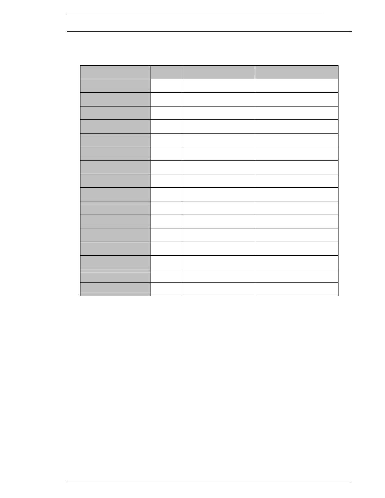
3.3.4 RS232C Data Format Description
The table below describes the data convention output from the RS232C serial port on the front
display.
Non-data bytes will be occupied by the hex character 20H.
Data Name
Byte # Data Format
Description
Cycle Count
Spindle Number
Parameter Number
Peak Torque
Peak Torque Judgment
Final Angle (degrees)
Final Angle Judgment
Final Torque
Final Torque Judgment
1st Time
1st Time Judgment
2nd Time
2nd Time Judgment
Total Judgment
Carriage return
1 ~ 4 0000-9999
7 ~ 8 01
12 ~ 13 1 – 8
16 ~20 0.234
21
23 ~ 26 1234
27
29 ~ 33 0.234
34
57 ~ 61 123.4
62 H: High Reject
64 ~ 68 123.4
69 H: High Reject
73
77 ODH
H: High Reject
L: Low Reject
H: High Reject
L: Low Reject
H: High Reject
L: Low Reject
O: Accept A: Abnormal
X: Reject S: Stop
Number is reset at Power Off
Always Spindle 1
Maximum 8 parameters
Decimal point location fixed
ASCII space (20H) will apply if
judgment is accepted
4 digit number. No decimal
point used
ASCII space (20H) will apply if
judgment is accepted
Decimal point location fixed
ASCII space (20H) will apply if
judgment is accepted
Decimal point location fixed
ASCII space (20H) will apply if
judgment is accepted
Decimal point location fixed
ASCII space (20H) will apply if
judgment is accepted
Line feed
78 OAH
Page 3-7
Page 32
Chapter 3: System Description
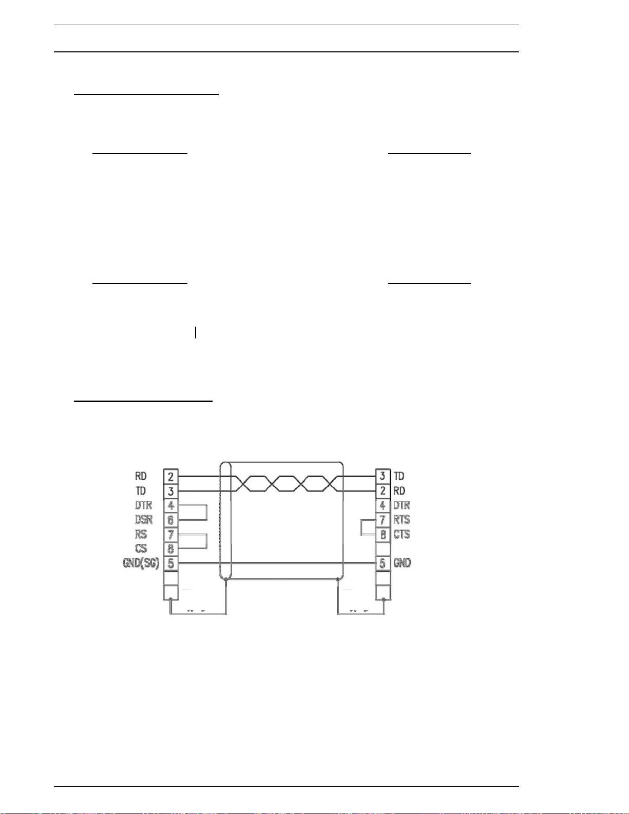
3.3.5 Cable Connection to Front Display
9-Pin to 25-Pin cable example
1. Connection using DTR signal
D-Sub 9-Pin Socket Cable Drawing D-Sub 25-Pin Pin
MNR TD 3 ------------------------------------------------- 3 RD
RS232C RD 2 Serial device
CTS 8 ------------------------------------------------- 20 DTR
GND 5 ------------------------------------------------- 7 GND
2. Connection for outputting unconditionally after fastening
D-Sub 9-Pin Socket Cable Drawing D-Sub 25-Pin Pin
MNR TD 3 ------------------------------------------------- 3 RD
RS232C RD 2 Serial device
RTS 7 ---- CTS 8 ----- (Pin 7 & 8 are jumpered)
GND 5 ------------------------------------------------- 7 GND
9-Pin to 9-Pin cable example
Device Side MNR Controller Side
(PLC, Computer, etc)
Page 3-8
Page 33
FEC Micro Nutrunner Operations Manual Chapter 3: System Description (Rev 2: 02/12)
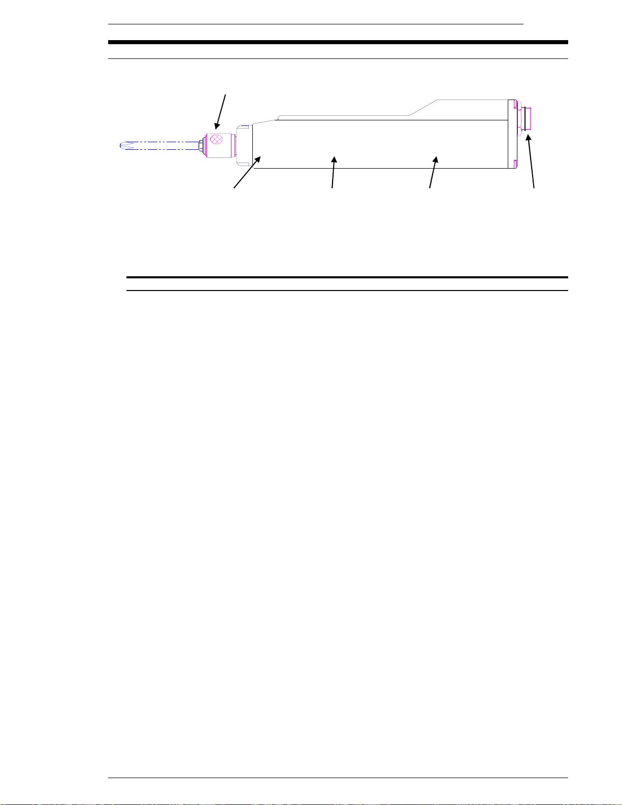
3.4 Nutrunner (Tool) Unit
{ RESOLVER
{ MOTOR
{ TRANSMISSION
{ TORQUE TRANSDUCER
{ PREAMP (Part of Torque Transducer)
{ CABLE CONNECTOR
{ BIT HOLDER
(Refer to Chapter 4 for complete tool and mounting dimensions.)
Bit Holder – ¼”
Torque Transducer Transmission Motor / Resolver Cable Connector
FIG. 3-5a Micro Nutrunner (Tool) Unit components
P Provides feedback for speed regulation to Servo Amplifier.
P Provides angular rotation monitoring capability to fastening operation.
P Totally enclosed DC permanent magnet motor.
P Durable Planetary gear transmission.
P Highly accurate strain gage transducer.
P Highly Durable, compact design minimizes space requirements.
P Intelligent transducer design accomplished through the use of an “ID Chip”
P “ID Chip” data used to verify integrity of fastening operations.
{ Single Cable connection using durable threaded connector
P ¼” quick change bit holder
Page 3-9
Page 34

Chapter 3: System Description
[Blank Page]
Page 3-10
Page 35

FEC Micro Nutrunner Operations Manual Chapter 4: System Setup and Wiring (Rev. 2.1: 12/12)
Chapter 4: System Setup and Wiring
Page 4-1
Page 36
Chapter 4: System Setup and Wiring
4
162
4.5
155015
80
53.8
(60)
10.430
4.5
4
150
START
REV.
CAL RESET
DATA
PARM. D -NO.
MODE
SET
RS232C
SAN3-DP2
DATA
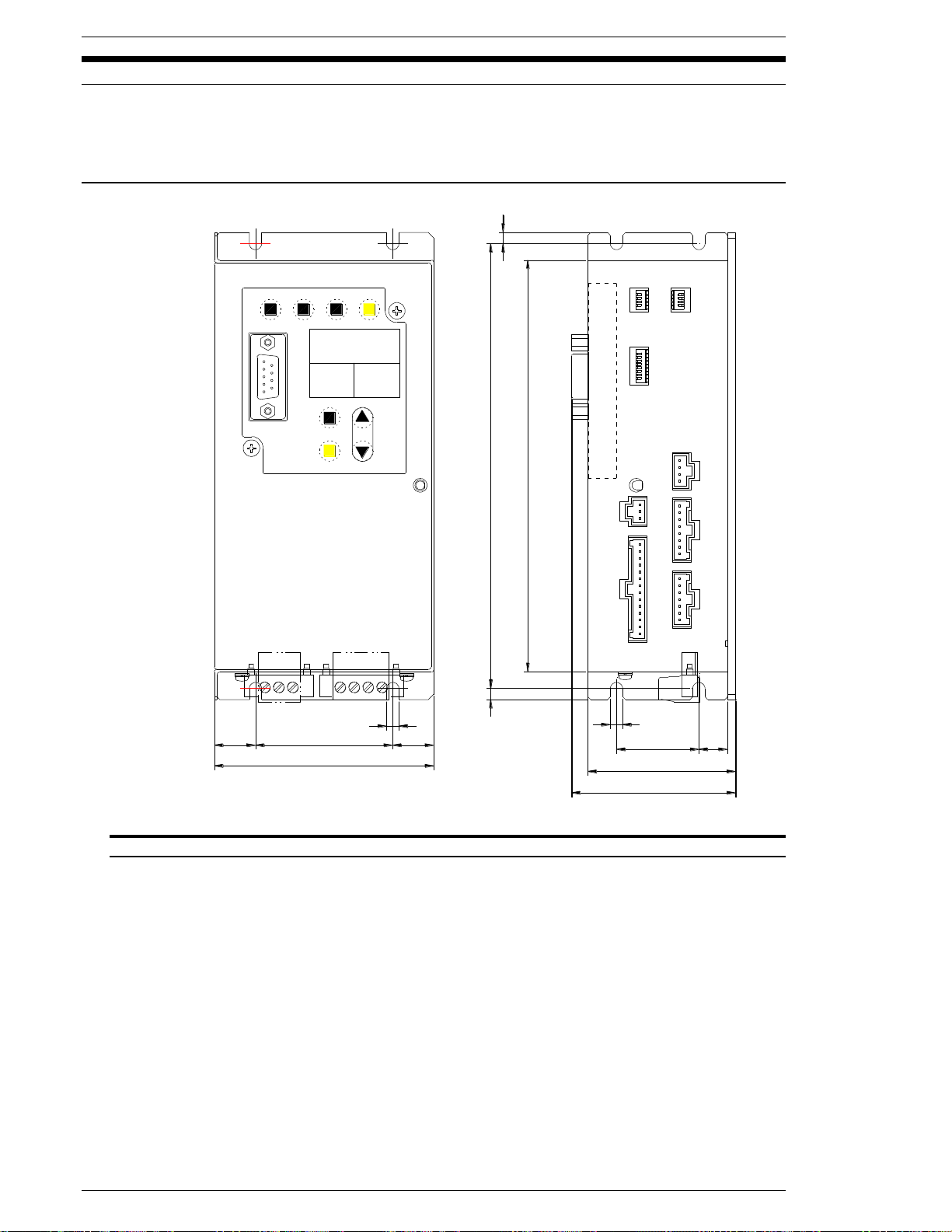
4.1 Component Dimensions
The specifications for all of the Micro NR standard system equipment is outlined in this Chapter to
aid in determining space, mounting and wiring requirements.
4.1.1 MNR Controller Unit Dimensions
Note: Dimensions shown in millimeters.
FIG. 4-1-1 MNR Controller Unit Dimensions
The Unit(s) must be mounted with a minimum clearance of 50 mm on each side to allow for
proper heat dissipation and cable connections clearance.
MNR Units must be located at a minimum 300 mm from any high transient voltage power source.
High transient sources such as relays, AC contactors, AC motor drives, etc. may cause
malfunction of the MNR unit.
All motor cables and I/O cables must be run separate from all high transient voltage sources.
When locating inside an enclosure, avoid mounting at or near the top where internal enclosure
heat is most extreme.
Page 4-2
Page 37
FEC Micro Nutrunner Operations Manual Chapter 4: System Setup and Wiring (Rev. 2.1: 12/12)
Tool Information
Tool Model
Torque
(Full Scale)
Speed
(Max RPM)
Weight
MFT-080M10-S
0.8Nm (7.08inlb.)
1100
605gram (1.33lb)
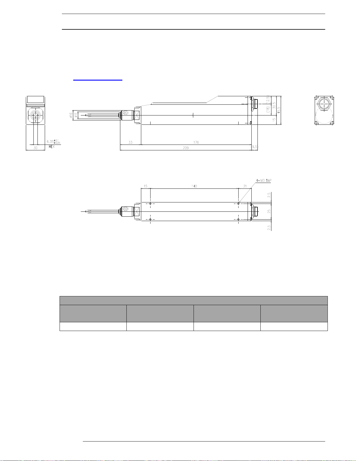
4.1.2 Tool
Tool dimensions and mounting specifications are critical in determining the design of the tool
mounting plate. Provide adequate clearance to ensure that tool assemblies do not come in
contact with any object. Failure to provide adequate clearance may result in torque inaccuracies
in the monitoring capability of the system or possible damage to the tool assembly.
Outline drawing Files of the tool are available via FEC Inc. website -
www.fec-usa.com, or by contacting FEC Inc. directly.
Dimensions shown in millimeters (mm)
For overall length with cable, add 95mm for cable connection (209mm + 95mm)
Note: Philips Bit shown in drawing above not included
WEIGHT CONVERSION GUIDE: 1 gram = .0022 lb
TORQUE CONVERSION GUIDE: 1NM = 8.85 in lb.
DIMENSIONAL CONVERSION GUIDE: 1mm = 25.4 Inch. Where noted – mm (Inch)
Page 4-3
Page 38
Chapter 4: System Setup and Wiring
POWER PIN
DESCRIPTION
1
Motor Power 24VDC
4.5amp min. power required
2
Control Power 24VDC
3
0VDC Common
MOTOR PIN
DESCRIPTION
1
Motor “U” Phase
2
Motor “V” Phase
3
Motor “W” Phase
4
FG
MOTOR
U V W FG
1 2 3 4
POWER
MP CP 0V
1 2 3
Mating Connectors:
Manufacturer: Phoenix Contact
Power Model #: MSTB 2, 5/3-STF-5.08
Motor Model #: MSTB 2, 5/4-STF-5.08
Type: Screw Terminal Type
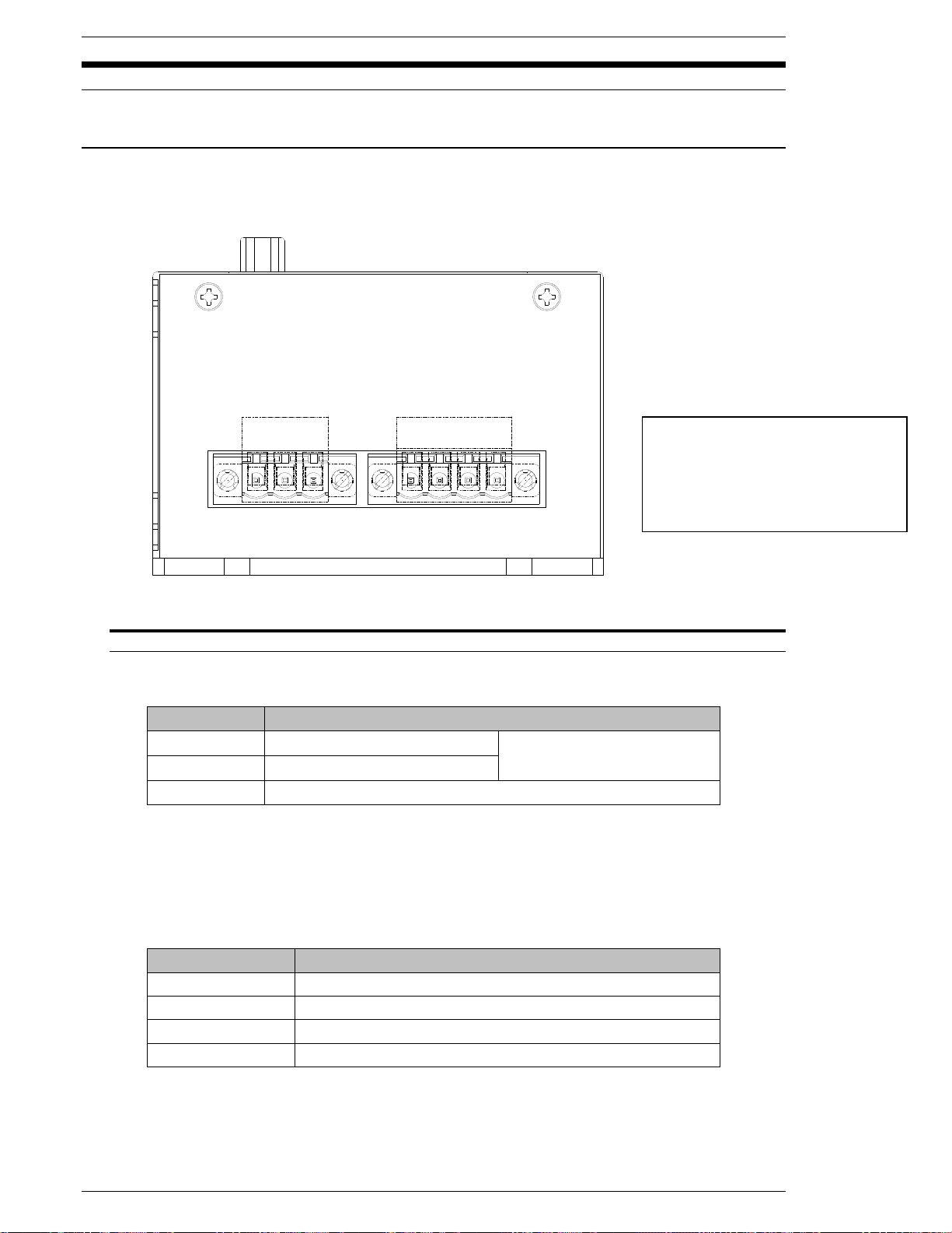
4.2 Power Requirements and Connections
4.2.1 MNR Unit
WARNING: Follow Lockout/Tagout and other safety precautions when connecting
and/or disconnecting cabling, wiring, and equipment.
Fig. 4-2-1 MNR Unit Input Power & Motor Connections
Recommended conductor size = 18 AWG
CAUTION: If the equipment is powered on and off repeatedly, internal circuit
protection devices may trip due to high in-rush current overload. It may take up to five
minutes of “off” time to clear the self-protection circuit. Please wait 15 seconds after
power down to power up.
Page 4-4
Page 39
FEC Micro Nutrunner Operations Manual Chapter 4: System Setup and Wiring (Rev. 2.1: 12/12)
Controller
DESCRIPTION
MNR-8
IDEC #NRC210L-5A-AA or Equivalent *
Controller
DESCRIPTION
MNR-8
TDK #ZRWT2205-ME (250V, 5A) or Equivalent
Controller
Cable Length
MNR-8
3 Meter Maximum
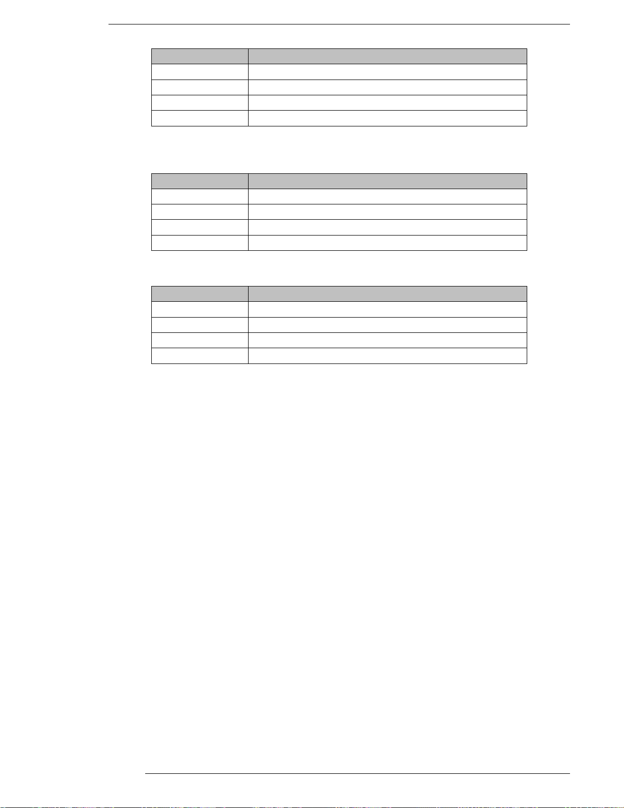
Circuit Protection
* Specify delay operation type.
Noise Filter
Motor Cable Length Limitation
Page 4-5
Page 40
Chapter 4: System Setup and Wiring
STATUS
PLC
CN2
T/D
RESOLVER
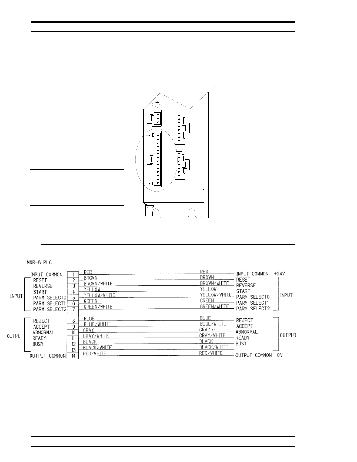
PLC Connector
Manufacturer: Hirose
Connector Model #: DF1E-14S-2.5C
Terminal Model#: DF1B-2428SC
or 0V
or +24V
4.3 Wiring PLC I/O
The MNR I/O can accommodate both active true low (sinking NPN) or active true high (sourcing
PNP) interface devices depending on the wiring configuration. (See PLC Wiring Example 4.4.3)
Outputs Max: 30V 50mA
Inputs Max: 30V 7mA
CAUTION:
The PLC I/O wiring must be routed a minimum of 300 mm away from
any transient high voltage sources. Cable length must not exceed 50 feet.
As viewed from the front of the MNR Unit.
FIG. 4-3-1 MNR Unit PLC Connector
Page 4-6
Page 41

FEC Micro NR Operations Manual Chapter 4: System Setup and Wiring (Rev2.1: 12/12)
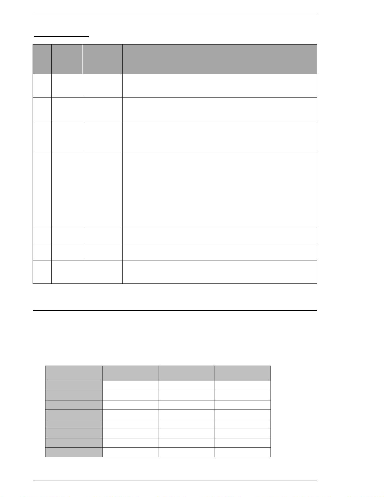
PLC Pin #
SIGNAL
TYPE
SIGNAL NAME
DESCRIPTION
1
INPUT COMMON
Input signal common. Connection to either +12 ~ 24 VDC or
OVDC common required. (Reference PLC wiring example)
2
INPUT
RESET
Reset Input
When active (on), this signal will clear all fastening data and
discrete outputs. A Zero Check of the torque transducer will be
completed. During the Zero Check, ACC (Accept) or REJ
(Reject) will be shown on the front display light to indicate the
result of the Zero Check. If the System has been disabled by an
Abnormal output, the System will not return to normal operation
until the Abnormal condition has been corrected and this signal
has been input for 100~500 milliseconds.
Do not input this signal between cycles due to the potential for
data loss.
3
INPUT
REVERSE
Reverse Spindle Rotation Input
The spindle will rotate in an opposite direction for as long as this
signal is activated (on) and maintained. The Reverse input
functions the same as the reverse push-button on the front of the
MNR display unit.
4
INPUT
START
Start Cycle Input
The Start input automatically resets the previous cycle, clears all
data to zero, and initiates the next fastening cycle. The Start
input requires a pulse of 100~300 milliseconds if the MNR Unit
DIPSW1 switches (bit 1) are set up for AUTOMATIC Start input.
If the MNR Unit DIP switches are set up for DEADMAN input, the
Start input must be maintained "on" for the entire cycle (until the
BUSY signal goes low).
5
INPUT
WORK SELECT 0
Work / Parameter Select Input (Normally Open)
These 3 inputs form a binary code which is capable of selecting
up to 8 different sets of Fastening Parameters. These inputs are
read at the rising edge of the START signal and select the
parameter to run according to these inputs.
Refer to Section 4.7.2 Work / Parameter Select Table.
6
INPUT
WORK SELECT 1
7
INPUT
WORK SELECT 3
4.3.1 Explanation of SAN Unit I/O
INPUT SIGNALS
Page 4-7
Page 42
Chapter 4: System Setup and Wiring
PLC
Pin #
SIGNAL
TYPE
SIGNAL
NAME
DESCRIPTION
8
OUTPUT
REJECT
Output when the fastening result is a REJECT. Indicates that the
spindle has failed the fastening limits. This output remains active until the START signal or RESET signal is input.
9
OUTPUT
ACCEPT
Output when the fastening result is a ACCEPT. Indicates that the
spindle is within the fastening limits. This output remains active until
the START signal or RESET signal is input.
10
OUTPUT
ABNORMAL
Output when an ABNORMAL condition occurs. Indicates that the
System has detected an internal fault and can no longer proceed.
An Abnormal condition must be corrected before the System will
resume normal operation.
11
OUTPUT
READY
Output when the system is in READY condition to operate and inputs
are enabled. This signal is inactive (off) in the following cases:
- Upon power-up while the processor is initializing (approx. 5sec.)
- During a Reverse operation
- When an Abnormal occurs
- During User Console communication
- When the BUSY signal is active (on)
- When the Reset or CAL button is being pressed
- When operation of the MNR Unit by an external input is
impossible
12
OUTPUT
BUSY
Output after a START signal is received and active until the fastening
cycle is complete and the READY signal is output.
13
OUTPUT
WARNING
Output when available memory size of the Micro SD card for data
storage becomes less than 10% of total memory size.
14
OUTPUT
COMMON
Output signal common. Connection to +24VDC or 0 VDC required
(Reference PLC wiring example)
PARAMETER
NO.
WORK
SELECT 2
WORK
SELECT 1
WORK
SELECT 0
1
OFF
OFF
OFF
2
OFF
OFF
ON
3
OFF
ON
OFF
4
OFF
ON
ON 5 ON
OFF
OFF
6
ON
OFF
ON 7 ON
ON
OFF
8
ON
ON
ON
ON = Enabled
OFF = Disabled
OUTPUT SIGNALS
4.3.2 Work / Parameter Select Table
WORK SELECT Inputs provide a means to change the preset parameter sets when the system
uses multiple fastening specifications. These three bits are used in a binary fashion to select up
to 8 different parameter sets.
With none of the bits enabled, the system will automatically use parameter set #1. The WORK
SELECT inputs must be selected at least 250ms BEFORE the start signal is activated.
Page 4-8
Page 43
FEC Micro NR Operations Manual Chapter 4: System Setup and Wiring (Rev2.1: 12/12)
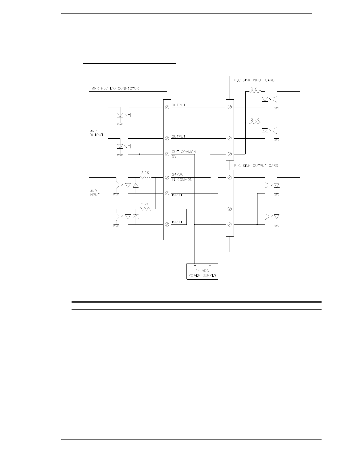
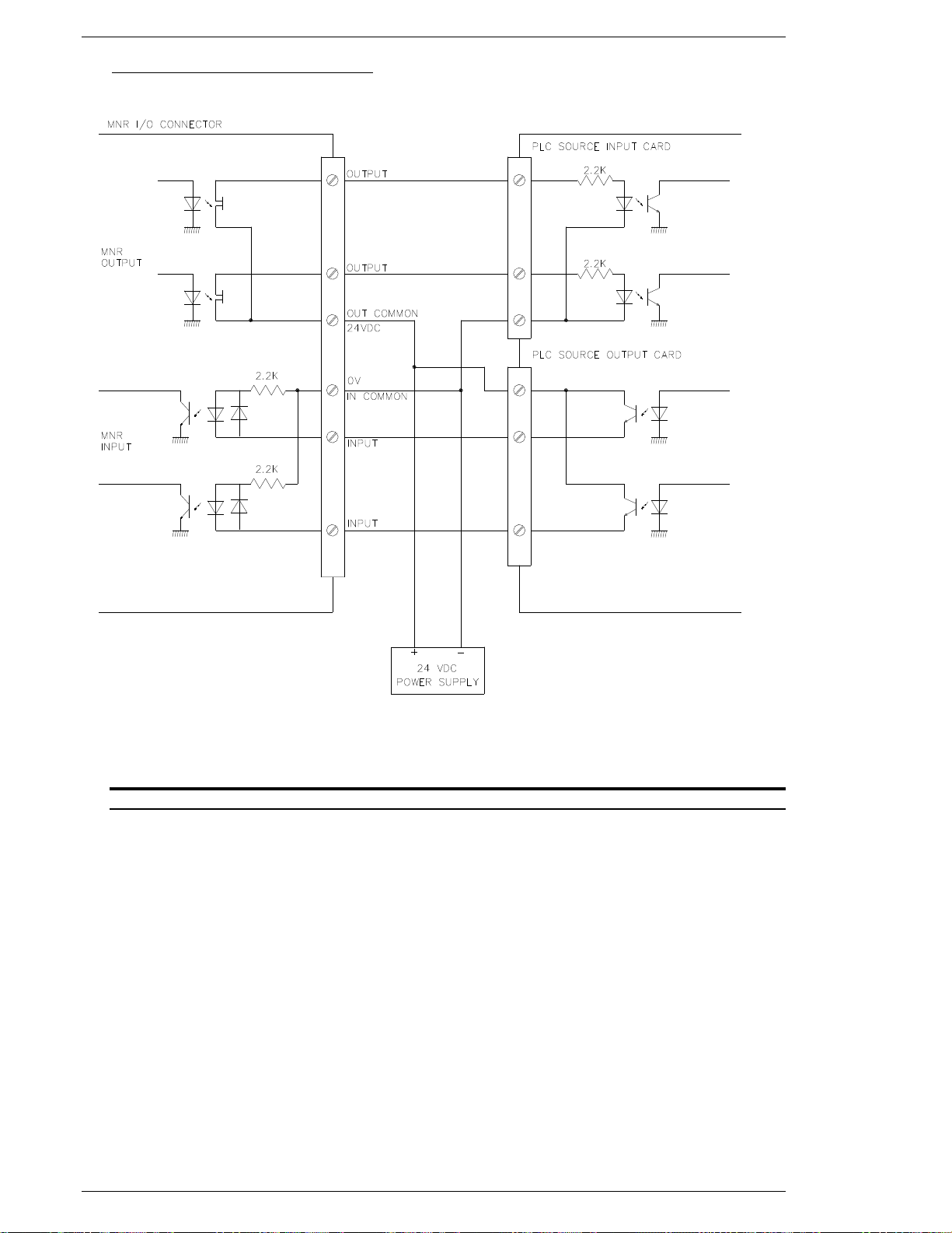
4.3.3 PLC Wiring Example
This diagram represents standard I/O connections. The I/O can be connected to either a NPN
(Sinking) or PNP (Sourcing) PLC I/O card. See below for wiring examples of both.
NPN (Sinking) Connection reference
FIG. 4-3-3-a PLC Wiring Example (Sinking)
To ensure correct operation of MNR output circuits, do not connect to an input device with high
Input resistance.
Page 4-9
Page 44
Chapter 4: System Setup and Wiring
PNP (Sourcing) Connection reference
FIG. 4-3-3-b PLC Wiring Example (Sourcing)
To ensure correct operation of MNR output circuits, do not connect to an input device with high
Input resistance.
Page 4-10
Page 45
FEC Micro NR Operations Manual Chapter 4: System Setup and Wiring (Rev2.1: 12/12)
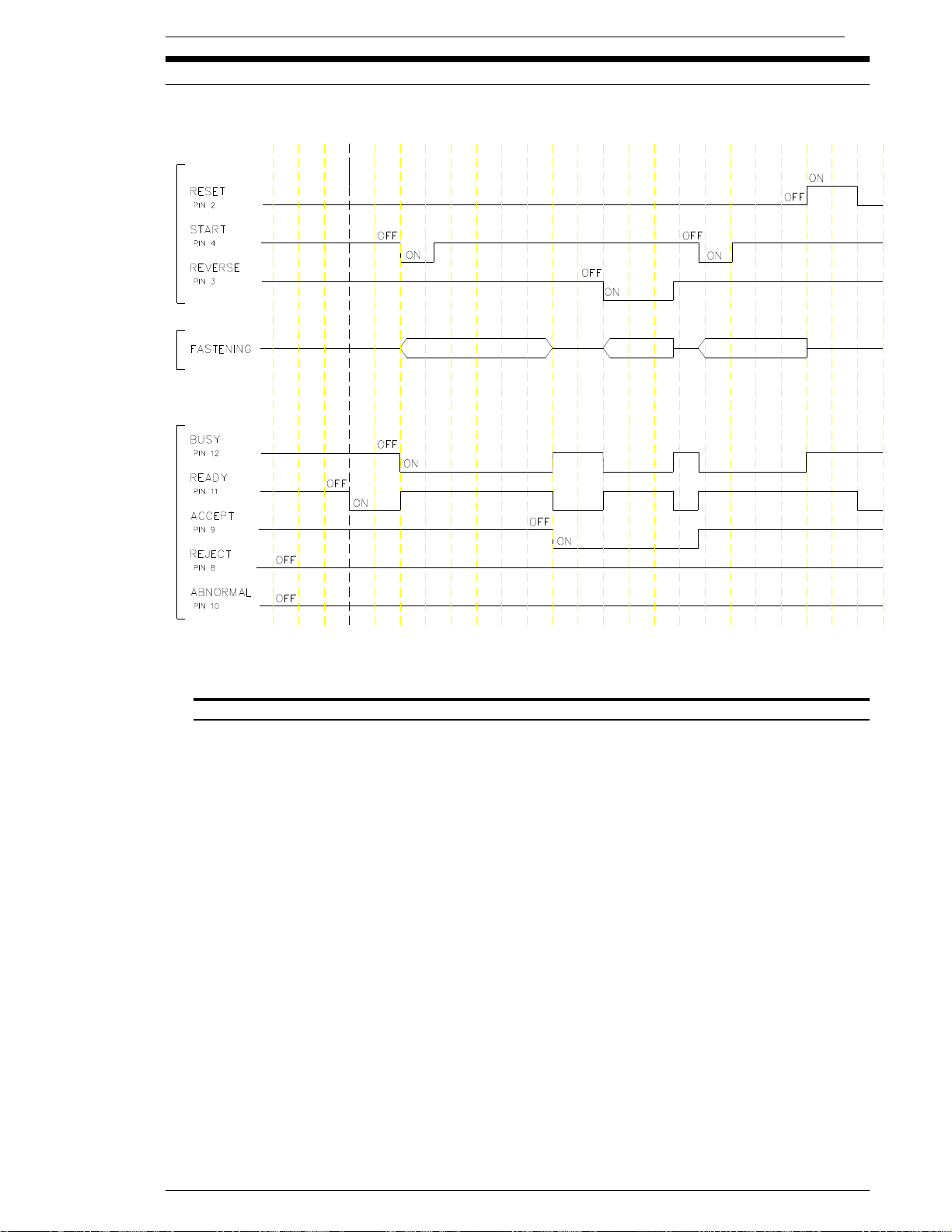
4.4 Signal Timing Chart
A. Basic Control Signals
FIG. 4-4 Basic Control Signals
{ Because the RESET input clears all fastening data, discrete outputs and communication
buffers, it should be activated only to clear a System Abnormal or to perform a required Zero
Check. The System will automatically reset with each fastening and a manual RESET
activation between cycles could result in data loss. The RESET signal requires a pulse of
100~500 milliseconds.
{ Once set on, the ACCEPT or REJECT signals will latch on until the start of the next cycle.
{ The START signal will not operate during RESET, REVERSE or ABNORMAL signal
activation. The START signal requires a pulse of 100~300 milliseconds for the AUTO START
mode. If the system is set-up in DEADMAN mode (Used mainly in handheld applications), this
signal has to stay on during the complete fastening cycle (until the BUSY signal goes low). If
the signal is prematurely disabled before the end of cycle, the spindle will immediately stop.
{ When the ABNORMAL signal is active, normal operation will cease. The Abnormal problem
must be cleared and a RESET must be input to clear the Abnormal output to begin normal
operation.
{ When using WORK SELECT inputs to change parameters activate or select the WORK
SELECT inputs at least 200ms BEFORE activating the start signal.
Page 4-11
Page 46
Chapter 4: System Setup and Wiring
USB
MEMORY
CARD
STATUS
CN2
SW1
MON
T/D
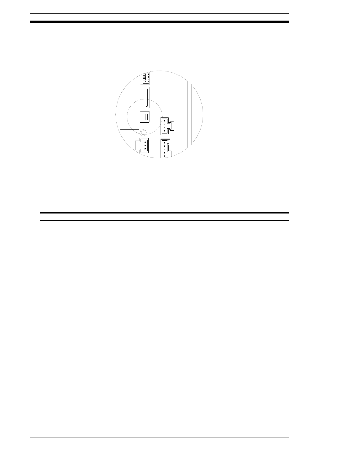
4.5 USB Communication Port
Communication to a PC and accompanying software is done through the mini USB port.
Connection from your PC USB port and this Mini USB port can be done with a standard USB Mini
cable. The Micro NR software will allow programming and monitoring of the Micro NR system.
Note: If using the USB port for PC connection to the accompanying software, the RS232C port
cannot be used for the same software communication at the same time. (Only one port can be
used at any one time for software communication)
Mating Connector: Mini USB
FIG. 4.5 USB port connector
Page 4-12
Page 47
FEC Micro NR Operations Manual Chapter 4: System Setup and Wiring (Rev2.1: 12/12)
CN2
SW3
SW2
SW1
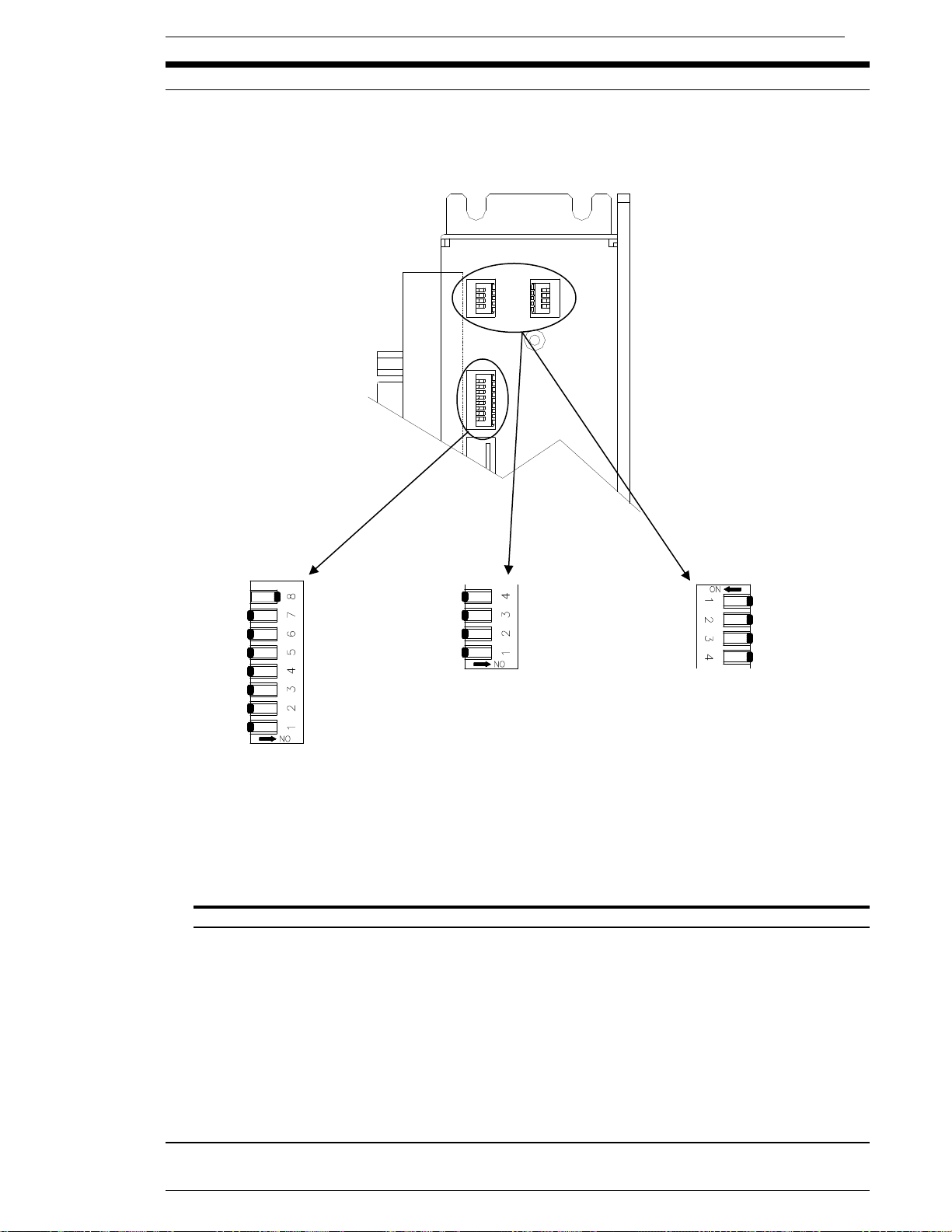
4.6 MNR Unit DIP Switch setting.
The MNR Unit has three DIP switches used for configuration setting. SW1, SW2 & SW3 are
located on the front of the MNR unit.
SW1 Orientation SW2 Orientation SW3 Orientation
(See below for setting) (Not Used – Set all OFF) (Not Used – Set all OFF)
FIG. 4-6 Dip Switches
Page 4-13
Page 48
Chapter 4: System Setup and Wiring
SNUG TQ
50°
40 °
SNUG TQ
4.6.1 MNR Unit DIP SW1 Settings
{ Switch 1 – START Signal Type .
P ON – Deadman (must hold START signal on for complete cycle)
P OFF – Pulse (200ms pulse required for start)
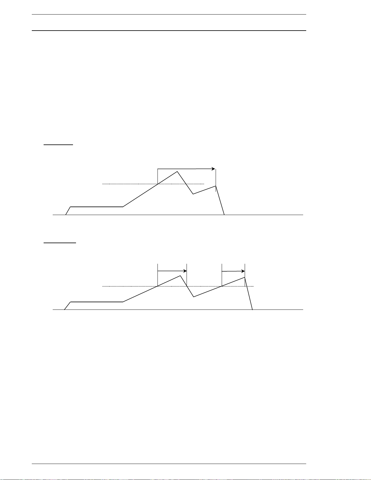
{ DIP Switch 2 – Snug Angle Count Method
P ON – Angle count starts at SNUG torque and continues whether SNUG torque remains
above or below once angle count starts
P OFF – (DEFAULT) Angle count starts at SNUG torque and only counts angle when
torque is at or above SNUG torque
SW1-2 ON
[In case Standard Angle is 90°]
90 °
SW1-2 OFF
[In case Standard Angle is 90 °]
{ DIP Switch 3 – Display Mode
P ON - Special
P OFF - Standard
{ DIP Switch 4 – 7.
P Always OFF
{ DIP Switch 8. – Enable X-Y curve save to SD Memory
P OFF – Disabled
P ON - Enabled
***Additional setup required See 7.4.6.1
NOTE: The MNR unit must be powered off and on again after any DIP switch change.
Page 4-14
Page 49
FEC Micro NR Operations Manual Chapter 4: System Setup and Wiring (Rev2.1: 12/12)
4.7 Tool Connection
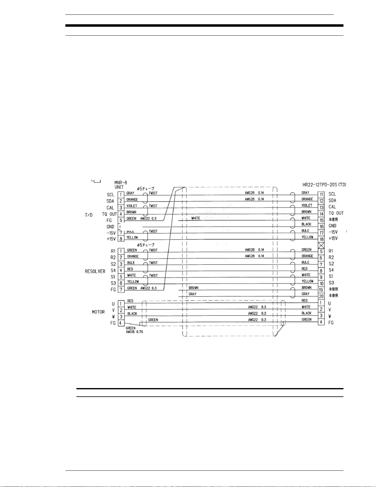
{ Tools are connected to the MNR controller using one cable (Cable supplied standard with
each spindle). One cable contains the motor, resolver and torque transducer signal cables.
Cable should be securely tightened to the motor to insure complete connection.
{ If cable ties are required, cable ties should be loose enough to allow the cable to move, but yet
hold it in place. Cable ties too tight cause a stress point leading to premature cable failure.
WARNING: Use cylinder cushions or shock absorbers to decelerate the tool head motions
and prevent excessive (hard stop) vibration, especially in short cycle time applications
operating at high speeds. Repeated shock (over time) could damage a tool.
WARNING: Do not make motor connections with the power on. Turn off all controller
power before attempting to connect or disconnect any motor cables or tool damage may
occur.
Tool Cable Assembly- # E0431000A Nominal OD = 9mm (.35”) Min. Bend Radius = 4.0“
Cable length: 3 meter Maximum Cable Length: 3 Meter
FIG. 4-7 Tool Cable Wiring Diagram
Page 4-15
Page 50

Chapter 4: System Setup and Wiring
4.7.1 Cable Installation Guidelines
Improper installation of cables can reduce cable life expectancy drastically. The following
guidelines should be used when installing cables.
The cables must be prepared for installation without twists, bends or kinks. Upon
unpacking the cables, any tie wraps used in shipping should be removed.
Before inserting the cables in the cable tray, cable track or other overhead suspension, it
is important that the cables be laid out or hung prior to installation long enough to relax
any stresses and remove any “memory” resulting from packaging, transit or storage. If the
cables cannot be relaxed, they should be shook out by grasping the cable length at its mid
point and shaking the cables as you move to each end. Then, wrap the end of each cable
with masking tape and make alignment marks on the top of each end. Maintain this
alignment throughout the installation to assure cable is not being twisted.
The minimum recommended bending radius of the cable should not be exceeded. The
minimum bend radius is calculated by multiplying the cable’s outer diameter by ten
(Rmin = O.D. x 10). When multiple cables are run together, the largest diameter cable in
the bundle should be used for calculating bend radius. Minimum bend radius must be
increased when repeated flexing occurs at a given point on the cables.
Use the most direct path when routing cables.
Do not weave cables between or wrap around one another.
Route cables and connectors away from liquid of any type.
Protect cable connectors from any impact or abrasion that may cause damage (IE: pulling
cables through cable tray and dropping cables to the floor).
Check cable route for possible chafing or abrasion points. Re-route or protect cable at
these points with a nylon cable wrap or similar means to avoid future cable damage.
The use of plastic cable ties (ty-wraps) should be avoided if possible. The use of Velcro
straps is preferable. If the use of plastic cable ties cannot be avoided, the following
practices should be followed:
o Cables should not be tied so tight as to cause indentations in the cable jacket.
Flexible cables are designed to move inside their cable jacket. If this
movement is restricted, wires in the cable may become stressed and break.
o Plastic cable ties around grouped cables should be used minimally so that
cables have the ability to move individually rather than all as one.
o An acceptable method is to include the use of a flexible tubing or sleeve
between the plastic cable tie and the cable(s).
Do not tie or hang anything, whatsoever, from tool cables.
Avoid running cables directly next to high voltage or high frequency lines.
Cables must be supported near connectors in panel and at tool to avoid strain on
connection points.
Certain tool operations may have foreseeable cable damaging aspects which are
unavoidable. In these situations a shorter “extension” cable can be provided with the
expectation of replacing this intermediate, less expensive cable as required. The use and
proper placement of an “extension” cable will also make cable replacement less time
consuming.
Page 4-16
Page 51

FEC Micro NR Operations Manual Chapter 4: System Setup and Wiring (Rev2.1: 12/12)
4.7.2 Considerations for Cable Trolleys
Cables hung by festooning type systems must be secured to the individual cable trolley and
positioned to avoid sharp bends and eliminate or minimize any torsion twisting.
Restraint cords should be used in between cable trolleys to limit movement and reduce the
stress on cables as they are extended. Restraint cord lengths must always be shorter than the
length of cable hung between trolleys.
Cable loops should be consistent in length,typically not exceeding 5 feet in depth between
trolleys. Sufficient number of trolleys should be used in a system to support the entire length of
moving cable and to allow relaxed stacking/festooning of cable loops when tool is in the
retracted position.
One trolley should be fixed to the runway rail to eliminate tugging on or stretching of cables.
4.7.3 Considerations for Flexible Cable Tracks
Cables must under no circumstances have the opportunity to tangle. Therefore the
clearance height of a track compartment with several similar cables next to one another must
not amount to more than one and a half times the cable diameter.
There should be an “all around” minimum clearance between cables of 10% of the cable’s
diameter.
Cables and hoses with very different diameters should be laid separately. Separation is
achieved by using Flexible Track separators. The following rules should be followed for cable
separation:
o If (Cable 1 Diameter) + (Cable 2 Diameter) > 1.2 x Track Inner Height, then no
separation is necessary.
o If (Cable 1 Diameter) + (Cable 2 Diameter) ≤ 1.2 x Track Inner Height, then a
horizontal or vertical separator must be used to reduce the inner height, thereby
preventing the entanglement of the cables.
The cable weight should be symmetrically distributed along the width of the track.
Cables must be able to move freely along the radius.
The cables must be secured with strain relief at both ends. In exceptional cases, the cables
may be fixed with strain relief at the moving end only. Unless using a Flexible Cable Track with
integrated strain relief, a gap of 10~30 x cable diameter between the end of the bending
segment and the fixed point is recommended for most cables.
Under no circumstances should excess cable be put into a Flexible Cable Track.
4.7.4 Considerations for Cable Trays & Ladders
Cable drop out panels should be used where cables enter and exit a tray or ladder system.
Sharp bends need to be avoided whenever possible.
Cables should be secured at both entry and exit points of a tray or ladder.
Avoid running high voltage or high frequency cables in the same tray or ladder as signal or
control cables unless cables are designed for such environments.
If excess cable is to be stored in a tray or ladder, do not tightly coil cable. Cable should be laid
in as large of a loop as possible.
Page 4-17
Page 52

Chapter 4: System Setup and Wiring
[Blank Page]
Page 4-18
Page 53

FEC Micro Nutrunner Operations Manual Chapter 5: Power Up and Initial Checks (Rev. 2: 02/12)
Chapter 5: Power Up and Initial Checks
Page 5-1
Page 54

Chapter 5: Power Up and Initial Checks
5.1 Before Powering On
WARNING:
disconnecting cabling, wiring, and equipment.
Follow Lockout/Tagout and other safety precautions when connecting or
Each item below lists the manual Section(s) that will provide a reference for that specific item.
Also refer to Section 3.1 System Block Diagram and Section 4.5 Wiring Diagram.
WARNING:
connected.
Damage may occur if the 24 VDC and 0 VDC Commons are improperly
1. Verify San Unit DIP switch settings (4.10)
P Verify that the SW1, SW2 and SW3 DIP switches visible on the side of each unit are set to
indicate the appropriate spindle number and options.
2. Confirm Interface (PLC) connection (4.7)
P Verify that the MNR Unit I/O interface wiring is connected to the corresponding PLC
terminals.
3. Check connections between the tool and the MNR Unit (3.2)
P Verify that the homerun cables connecting the tool and MNR Unit are secure. If the layout
contains moveable parts, visually inspect all components to ensure that there is proper
clearance and that cables have sufficient length. If movement would create any excessive
stress on a cable or create any potential for damage to the system or other components in
the layout, then make appropriate adjustments.
WARNING:
Do not make cable connections with the power on. Turn off all controller
power before attempting to connect or disconnect any motor cables or tool damage may
occur.
4. Check the input voltage (3.2, 4.6)
P Verify input power is properly connected (4.11.2).
P Ensure input power voltage to the MNR Unit is 24V DC.
P After turning on the power, verify the voltage again to ensure it has not dropped as a result
of loading.
NOTE: After an MNR unit is powered down, the power must not be applied again for at
least five (5) seconds. Repeated power up and power down may temporarily disable the
MNR unit. If an MNR unit does become disabled, keep the power off for five (5) minutes,
then power on again to reset the fault.
Page 5-2
Page 55

FEC Micro Nutrunner Operations Manual Chapter 5: Power Up and Initial Checks (Rev. 2: 02/12)
5.2 Initial Data Setting
After completion of the system verification/power on procedure in Section 5.1, the system is ready
for the input of data required for the fastening operation. Chapters 6 and 7 give details on the
types of information required and the procedure for entering data into the system. The system will
not run until this data is correctly set-up.
Programming all parameters should be performed using the FEC Inc. “MNR User Console”
software to simplify the programming operation and to provide a means of creating a back-up file
of the set-up.
NOTE: Most MNR systems are delivered with application-specific fastening data already setup
(if provided by customer). This set-up data is considered preliminary and should be adjusted
according to actual process / part runs for optimal performance.
Perform the following procedure by the front Display and Programming interface:
1. Check the transducer ZERO output.
P Press the RESET button on the front keyboard-display. The MNR will perform a “Zero
Voltage” check and signify the results with an “ACC” for Accept or an “REJ” for Reject on
the Data Display. The STATUS LED will also light with the appropriate color. (See NOTE 1
below.)
2. Check the transducer CAL output.
P Press the CAL button on the front keyboard-display. The MNR will perform a “CAL
Voltage” check and signify the results with an “ACC” for Accept or an “REJ” for Reject on
the Data Display. The STATUS LED will also light with the appropriate color. (See NOTE 1
NOTE 1: If the Zero and/or Cal check results in a "Reject" an “Abnormal” output will be
generated from the MNR Unit. Refer to Section 9 for guidance.
WARNING:
TOOL AREA PRIOR TO ACTIVATING A SPINDLE OR OTHER MOVEABLE COMPONENT.
3. Check manual reverse operation.
4. Verify operation of manual start.
5. Verify System operation by external commands.
below.)
VERIFY THERE ARE NO PERSONNEL OR OBSTRUCTIONS IN THE
P Press the manual REV button on the front keyboard-display. Verify that the spindle is
turning in the appropriate direction (opposite the preset direction).
P Press the START button and verify that the tool runs in the correct direction until the pre-
programmed time elapses, creating a reject.
P Press the RESET button on the operator panel to clear the “REJ” display and LED outputs
from the MNR Units.
P Confirm that the equipment operates correctly when PLC inputs and outputs are activated.
Use the PLC to perform all of the functions (START, REVERSE, etc.) that were manually
activated earlier in this Section.
Page 5-3
Page 56

Chapter 5: Power Up and Initial Checks
[Blank Page]
Page 5-4
Page 57

FEC Micro Nutrunner Operations Manual Chapter 6: Fastening Instructions (Rev. 2: 02/12)
Chapter 6: Fastening Instructions
Page 6-1
Page 58
Chapter 6: Fastening Instructions
This is the low angle limit for the fastening cycle. If this limit is
The snug torque
6.1 Fastening Control.
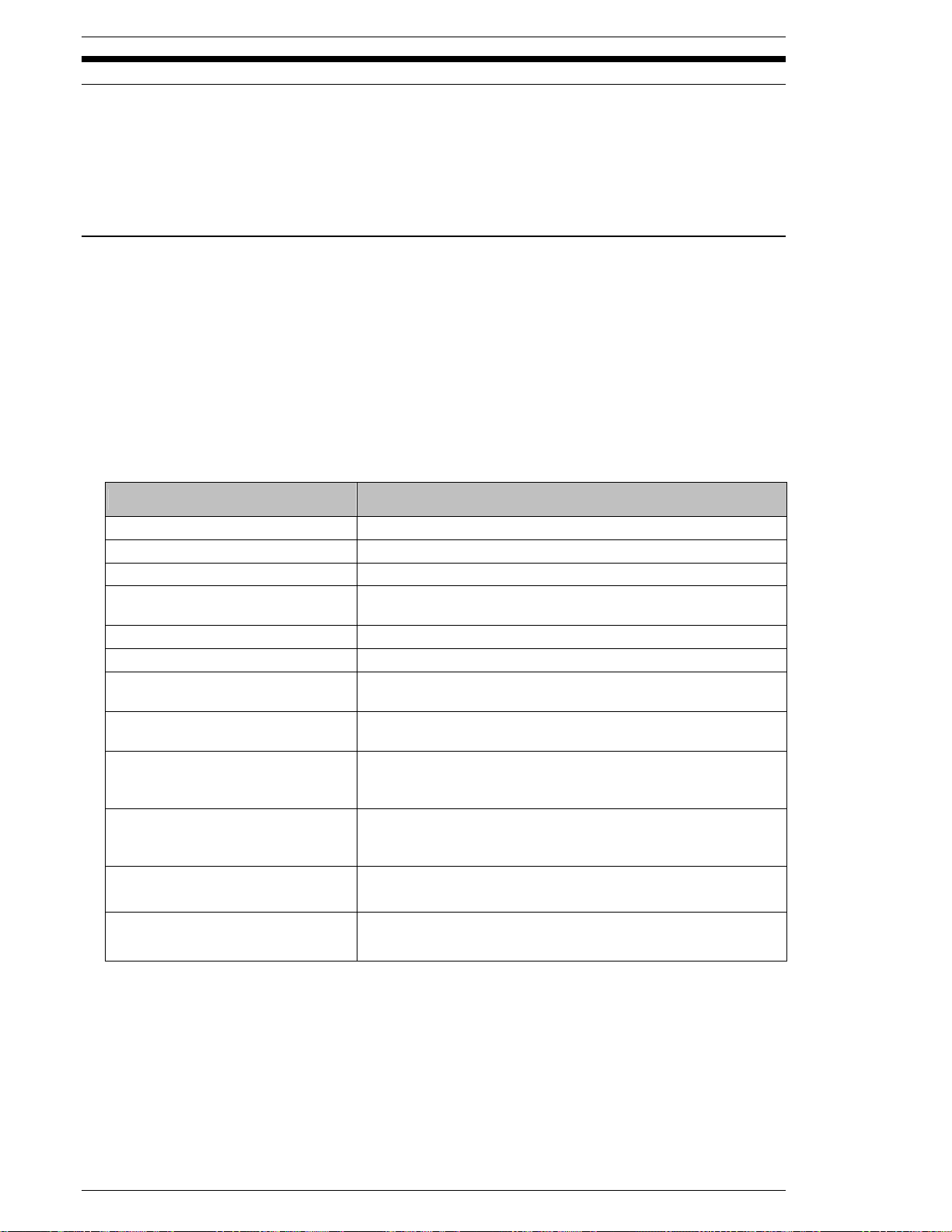
The Micro NR is presentable from two different fastening methods, by parameter setting Torque
Control or Angle Control methods. (Based on parameter setting)
NOTE: All setting recommendations are based upon common fastening applications.
Applications that experience high prevailing torque, excessive joint compression or other
unique characteristics must be set with these characteristics in mind.
6.1.1 Torque / Angle Method - Target Torque Control.
Fastening is performed based upon attaining a desired Torque value while monitoring the degrees
of rotation (Angle) of the fastener and time. Additional monitor items (limits) can be set to enhance
the system’s ability to determine if the fastener was properly secured (Section 6.2).
{{{{ Fastening Explanation
1. After start signal command the system runs INITIAL SPEED until INITIAL TIME expires.
2. Once FREERUN REVOLUTIONS or FREERUN TIME expires, the speed will switch from
FREERUN SPEED to SLOWDOWN SPEED.
3. Once SPEED CHANGE TORQUE is reached the speed runs at TORQUE SPEED to
fasten to STANDARD TORQUE. STANDARD TORQUE must be reached within the
FASTENING TIME LIMIT or a reject will occur.
FUNCTION RECOMMENDATION / COMMENT
14: SPEED CHANGE TORQUE 10% of STANDARD TORQUE
16: SNUG TORQUE Angle Monitoring Start Point (section 6.2)
13: STANDARD TORQUE Engineered product fastening specification (TORQUE)
22: STANDARD ANGLE
42: FASTENING TIME LIMIT Acceptance range to go from Cycle start to end of cycle.
11: PEAK TORQUE HIGH LIMIT
12: PEAK TORQUE LOW LIMIT
20: ANGLE LOW LIMIT
21: ANGLE HIGH LIMIT
68: RUNDOWN REVOLUTION
LOW LIMIT
69: RUNDOWN REVOLUTION
HIGH LIMIT
Set at 999.9 or high enough as not to inadvertently stop the
cycle and judge the operation based upon this value.
This is the high torque limit for the fastening cycle. If this limit
is exceeded the system will display reject.
This is the low torque limit for the fastening cycle. If this limit
is not achieved the system will display reject.
not achieved the system will display reject.
value is used for starting the angle count.
This is the high angle limit for the fastening cycle. If this limit
is exceeded the system will display reject. The snug torque
value is used for starting the angle count.
Numeric value that represents the minimum number of
revolutions during fastening cycle.
Numeric value that represents the maximum number of
revolutions during fastening cycle.
Page 6-2
Page 59
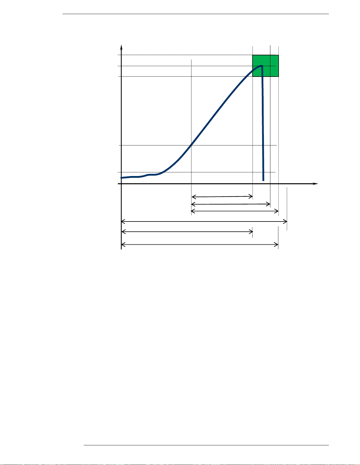
FEC Micro Nutrunner Operations Manual Chapter 6: Fastening Instructions (Rev. 2: 02/12)
Torque
12: Peak Torque High
13: Standard Torque
11: Peak Torque Low
16: Snug Torque
14: Speed Change Torque
Angle/Time
20: Angle Low Limit
22: Standard Angle
21: Angle High Limit
68: Rundown Revolutions Low Limit
42: Fastening Time Limit
69: Rundown Revolutions High Limit
Page 6-3
Page 60
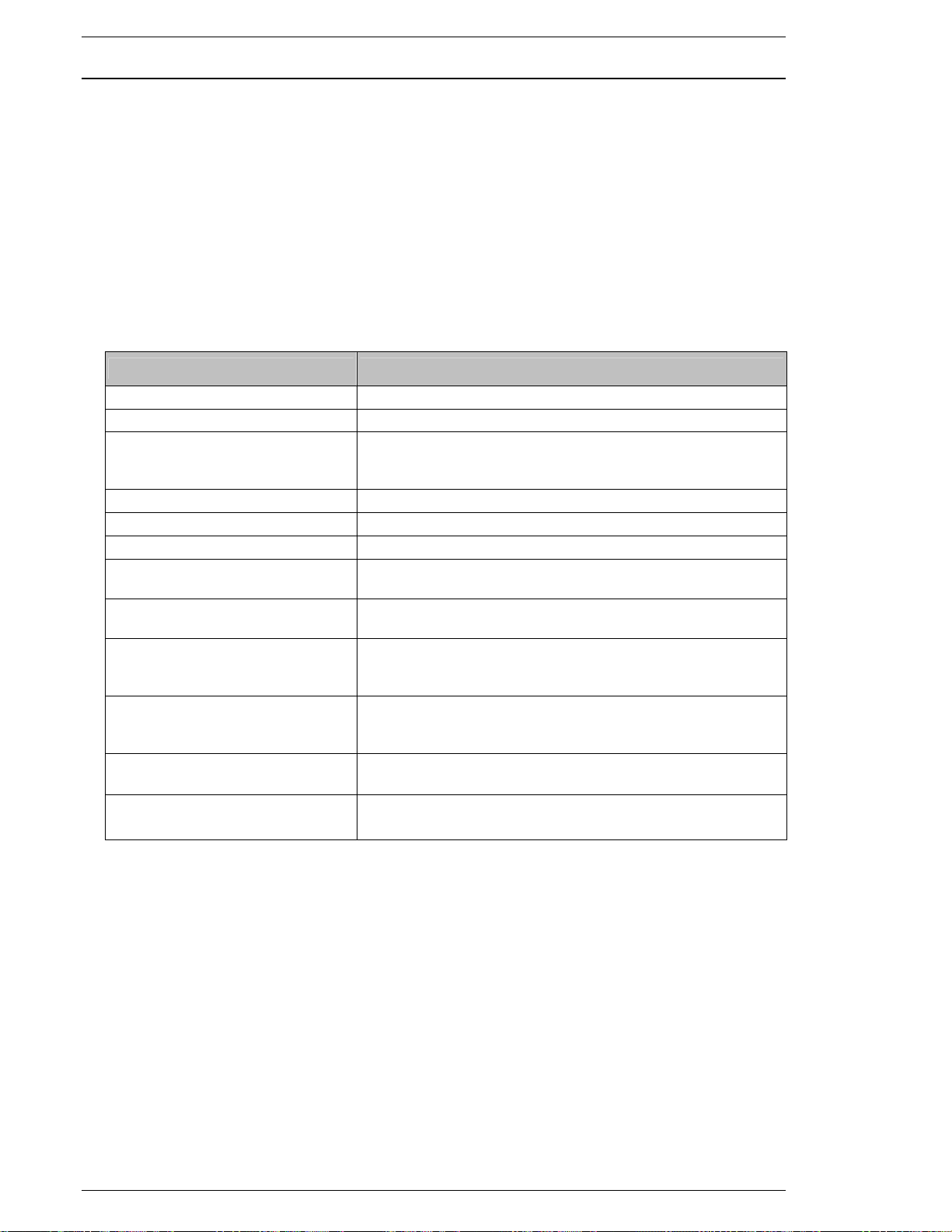
Chapter 6: Fastening Instructions
This is the low angle limit for the fastening cycle. If this limit is
The snug torque
6.1.2 Torque / Angle Method - Target Angle Control.
Fastening is performed based upon attaining a desired Angle value,
the fastener and time.
Additional monitor items (limits) can be set to enhance the system’s ability to
while monitoring the Torque of
determine if the fastener was properly secured (Section 6.2).
{{{{ Fastening explanation
1. After start signal command the system runs INITIAL SPEED until INITIAL TIME expires.
2. Once FREERUN REVOLUTIONS or FREERUN TIME expire, the speed will switch from
FREERUN SPEED to SLOWDOWN SPEED.
3. Once SPEED CHANGE TORQUE is reached the speed runs at TORQUE SPEED to
fasten to STANDARD ANGLE. STANDARD ANGLE must be reached within the
FASTENING TIME LIMIT or a reject will occur.
FUNCTION RECOMMENDATION / COMMENT
14: SPEED CHANGE TORQUE 10% of STANDARD TORQUE
16: SNUG TORQUE Angle Control Start Point (section 6.2)
Set at Calibration Torque or high enough as not to
13: STANDARD TORQUE
inadvertently stop the cycle and judge the operation based
upon this value.
22: STANDARD ANGLE Engineered product fastening specification (ANGLE)
42: FASTENING TIME LIMIT Acceptance range to go from Cycle start to end of cycle.
11: PEAK TORQUE HIGH LIMIT
12: PEAK TORQUE LOW LIMIT
This is the high torque limit for the fastening cycle. If this limit
is exceeded the system will display reject.
This is the low torque limit for the fastening cycle. If this limit
is not achieved the system will display reject.
20: ANGLE LOW LIMIT
21: ANGLE HIGH LIMIT
68: RUNDOWN REVOLUTION
LOW LIMIT
69: RUNDOWN REVOLUTION
HIGH LIMIT
not achieved the system will display reject.
value is used for starting the angle count.
This is the high angle limit for the fastening cycle. If this limit
is exceeded the system will display reject. The snug torque
value is used for starting the angle count.
Numeric value that represents the minimum number of revo-
lutions during fastening cycle.
Numeric value that represents the maximum number of revo-
lutions during fastening cycle.
Page 6-4
Page 61
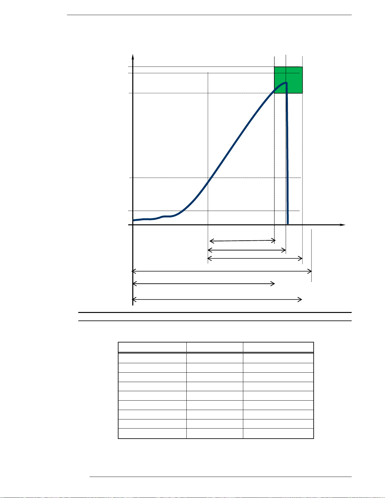
FEC Micro Nutrunner Operations Manual Chapter 6: Fastening Instructions (Rev. 2: 02/12)
12: Peak torque High Toque High
13: Standard Torque
11: Peak Torque low
16: Snug Torque
14: Speed Change Torque
Torque
20: Angle low limit
22: Standard Angle
21: Angle High limit
42: Final time High limit
68: Rundown revolution low limit
69: Rundown revolution high limit
FIG. 6-1-2a Angle Control Functions for One-Step Fastening
Angle/Time
MNR unit display User console display
Peak Torque YES YES
Final Angle YES YES
Final Torque YES YES
Cycle Time YES YES
Peak Current YES YES
Rundown Revolutions
YES YES
Snug Torque NO YES
TD Origin Voltage NO YES
TD CAL Voltage NO YES
Page 6-5
Page 62
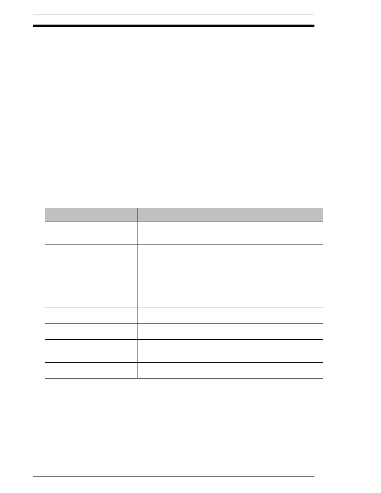
Chapter 6: Fastening Instructions
6.2 Speed Functions
The Micro NR System is user-programmable for operations involving multiple speed settings. The
use of multiple speeds during the fastening process aids in socket engagement, achieving cycle
time and controlling the applied torque during all stages. Special conditions that affect these
operations will be identified in the appropriate section.
1. Fastening Initial stage to seating process:
a. The system starts off running at INITIAL SPEED for the period specified by INITIAL
TIME. This segment is intended to be used for initial fastener engagement.
b. Upon completion of INITIAL TIME the system switches to FREERUN SPEED for the
period specified by FREERUN REVOLUTIONS or FREERUN TIME. The number of
revolutions or the set time required to complete INITIAL TIME will be deducted from
the number of revolutions run or amount of time at FREERUN SPEED.
c. Once FREERUN REVOLUTIONS or FREERUN TIME expires, the system will switch
from FREERUN SPEED to SLOWDOWN SPEED and continue to fasten until
reaching SPEED CHANGE TORQUE. SLOW DOWN SPEED is intended to provide
a slower, more controlled speed to seat the fastener.
2. Once SPEED CHANGE TORQUE is reached, the system will switch from FREERUN SPEED
or SLOWDOWN SPEED to TORQUE SPEED to continue fastening to STANDARD
TORQUE/ANGLE.
FUNCTION RECOMMENDATION
60: FREERUN REVOLUTIONS
41: FREERUN TIME
51: FREERUN SPEED
40: INITIAL TIME
50: INITIAL SPEED
52: SLOW DOWN SPEED
14: SPEED CHANGE TORQUE
53: TORQUE SPEED
54: REVERSE SPEED
For joints that do not react properly to high speed seating, the
Freerun Revolutions should be set to end prior to the fastener
seating.
For joints that do not react properly to high speed seating, the
Freerun Time should be set to end prior to the fastener seating.
Set based upon cycle time requirements. This speed is used to
run down the bolt quickly.
Set to a duration which will provide sufficient time for the socket to
engage the fastener. Set in seconds.
Set to the RPM which will allow for easy socket to fastener
engagement.
Seating speed. Set based upon the joint type to allow for a
controlled seating.
The tool speed shifts to TORQUE SPEED when the torque
monitor senses this torque value.
Final torque speed to which the nutrunner will shift once SPEED
CHANGE TORQUE is reached. Set based upon the joint type to
allow for a controlled final fastening. LESS THAN 50 RPM.
Speed used to reverse or back-out a fastener. Typically ¼ of full
speed.
Page 6-6
Page 63
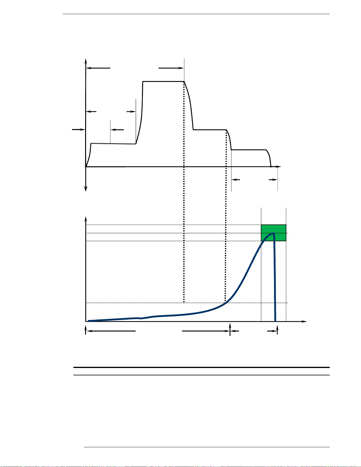
FEC Micro Nutrunner Operations Manual Chapter 6: Fastening Instructions (Rev. 2: 02/12)
14: Speed Change
Torque
Torque
Speed
Time
61: Torque Inhibit
Revolutions
Standard Torque
The graphic below describes the ideal relationship between torque and speed. Typically for high
motor durability, high speed (FREERUN speed) should slow to SLOWDOWN SPEED before the
fastener seats. Final TORQUE SPEED should not exceed 50 RPM.
Speed
60: Freerun
Revolutions
51: Freerun
Speed
40: Initial Time
50: Initial Speed
52: Slow Down
53: Torque
Speed
Time/Revolution
42: Final
Time
Angle/Time
41: FREE RUN Time
42: Final
FIG. 6-3b Ideal Relationship of Speed and Torque
Page 6-7
Page 64
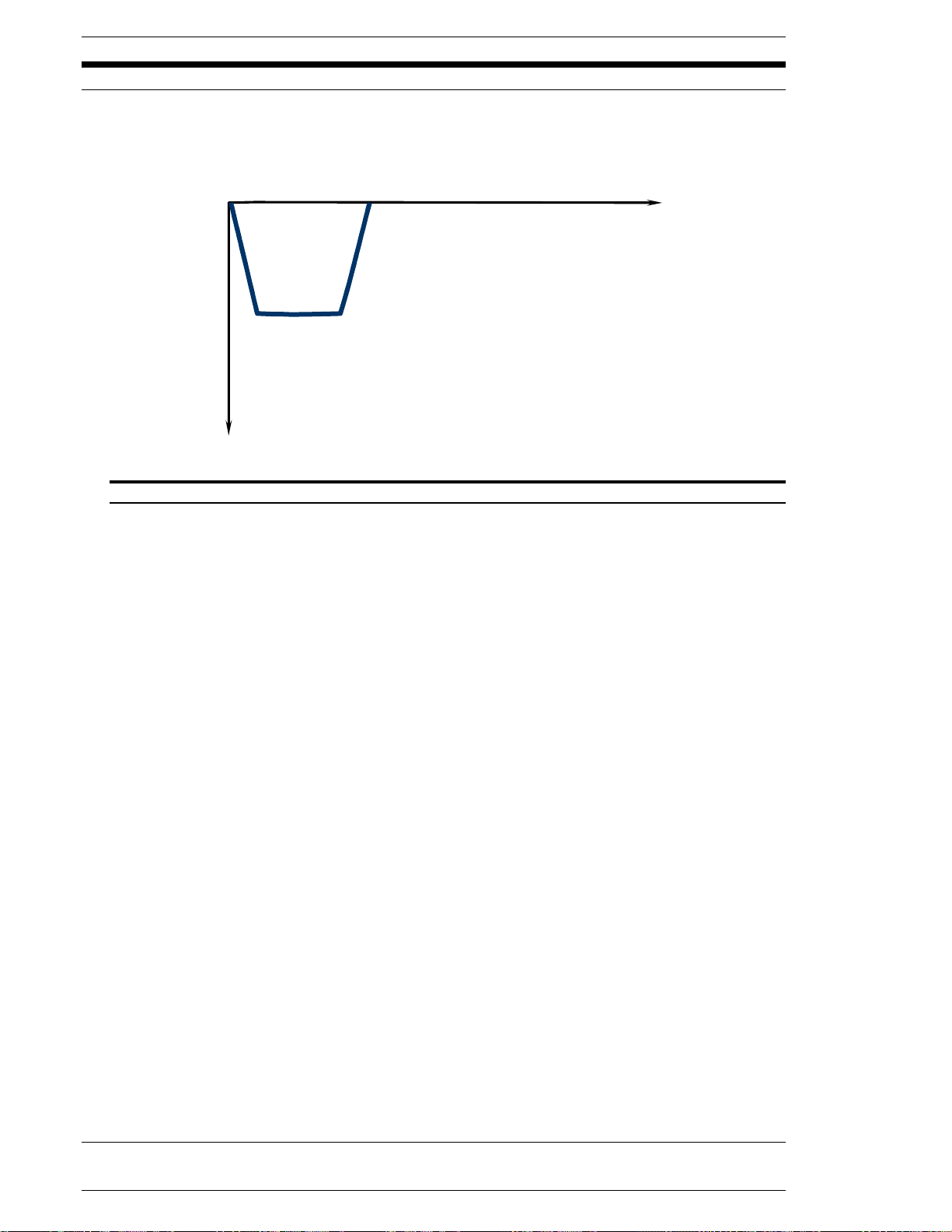
Chapter 6: Fastening Instructions
6.3 Reverse Function
The Micro NR System is capable of reverse operations using the manual reverse input on the
MNR unit front panel or via the PLC input. The PLC input can be used for automated reverse
operations. The motor will reverse as long as the reverse signal or manual button is enabled.
Time/Revolutions
54: Reverse Speed
RPM
FIG. 6-3 Reverse
Page 6-8
Page 65
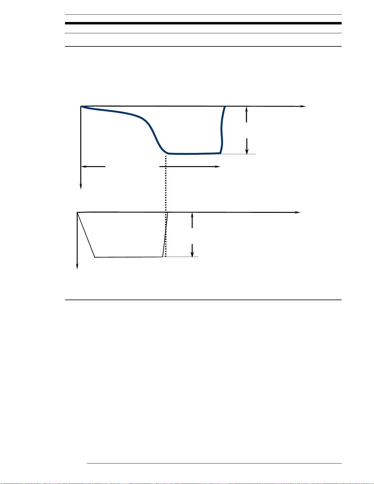
FEC Micro Nutrunner Operations Manual Chapter 6: Fastening Instructions (Rev. 2: 02/12)
6.4 Special Functions
6.4.1 One Pulse Reverse Function
One Pulse Reverse is used in applications where socket to fastener tolerances allow the fastener
to “stick” or lock into the socket during fastening operations. Upon completion of fastening, torque
is applied in the reverse direction for the full time specified by 1 Pulse Reverse Time, at the speed
specified by 1 Pulse Reverse Speed, allowing the socket to free itself from the fastener. This is
done without affecting the torque originally applied to the fastener by setting the 1 Pulse Reverse
Torque Limit to a lower Torque value.
Time
TORQUE
SPEED
1A: 1P Reverse Torque
64: 1P Reverse Time
Time
55: 1P Reverse Speed
Page 6-9
Page 66

Chapter 6: Fastening Instructions
6.4.2 Rundown Revolution Limits
Rundown Revolution high and low limits can be set to identify fasteners that may be too long or
too short for normal operations or for a redundant check for bolts that reach torque but are not
seated. This is especially the case where different length fasteners are used and placed by hand.
The number of rundown revolutions until fastening end is monitored and judged. Rundown
Revolutions is measured from the start of revolution to fastening end.
Note: Since fastener engagement is not always 100% guaranteed (and this is counted in
revolutions), bolt length differences must be enough for detection without setting limits too tight or
problematic rejects may occur. Also, if bolts are hand started (with a variable starting point) this
function is not recommended unless the bolts are pre-started to the same point every cycle.
Page 6-10
Page 67
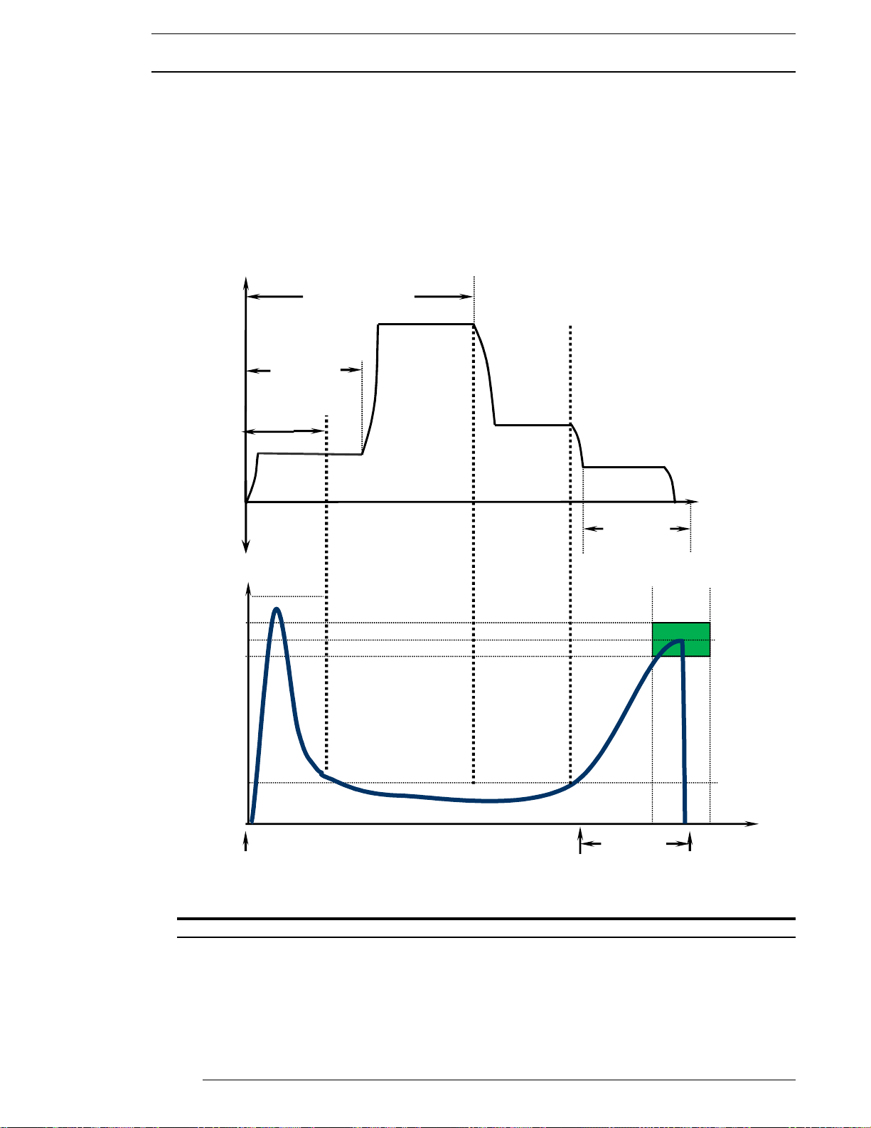
FEC Micro Nutrunner Operations Manual Chapter 6: Fastening Instructions (Rev. 2: 02/12)
14: Speed Change
Torque
Angle/Time
Speed
Speed
6.4.3 Torque Inhibit
The Torque Inhibit function is used to ignore high torque spikes during initial starting of the motor
or fastening process. Under normal fastening operations peak torque will stop the fastening
process (if Standard Torque is reached). This may not be desirable for applications with high
starting torque and lower fastening torque. Applications such as self-tapping screws and
application with high starting inertia may require this function.
Torque Inhibit is set by the number of revolutions that are required to be “ignored” during the
process. The Torque Inhibit Limit is a torque limit used as protection in case the amount of torque
monitored during the Torque Inhibit Revolutions is too high. If this torque limit is hit during the
Torque Inhibit process, then the spindle will stop and an Abnormal is output.
50: Initial Speed
19: Torque Inhibit Limit
WARNING: The Torque Inhibit Revolutions setting should be set as low as possible for the
intended application to avoid ignoring torque readings as the fastener approaches the
seating point. If the fastener seats and the system is still in Torque Inhibit mode, possible
fastener/part and/or system damage may occur.
61: Torque Inhibit
Revolutions
Torque
40: Initial
Time
60: Freerun
Revolutions
51: Freerun
Speed
52: Slow
Down Speed
Fig. 6-4-3 Torque Inhibit Function
53: Torque
42: Final
Time
42: Final
Time
Time/Revolutions
13: Standard Torque
Page 6-11
Page 68

Chapter 6: Fastening Instructions
[Blank Page]
Page 6-12
Page 69

FEC Micro Nutrunner Operations Manual Chapter 7: System Operations (Rev. 2.1: 12/12)
Chapter 7: System Operations
Page 7-1
Page 70
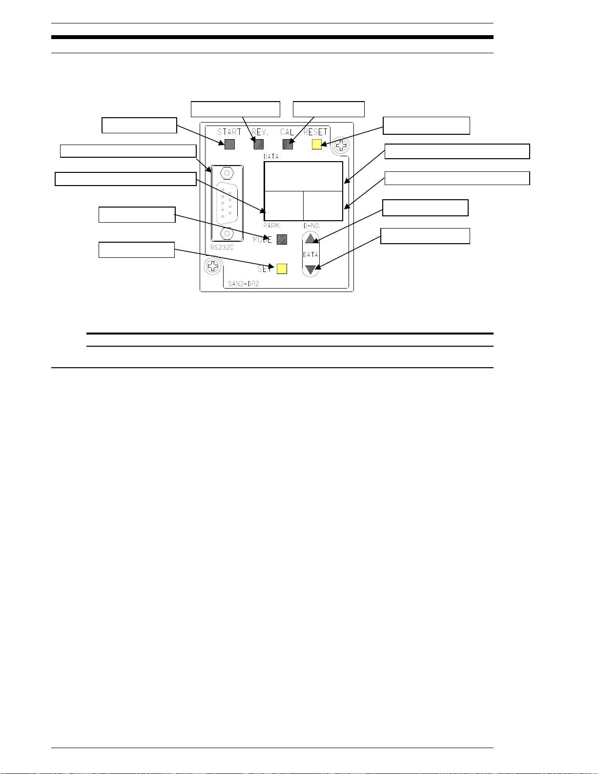
Chapter 7: System Operations
START Button
RESET Button
MODE Button
SET Button
DATA ↑Button
DATA ↓Button
REVERSE Button
CAL Button
DATA display (4digit)
D-NO display (2digit)
PARM display (2digit)
RS-232C Connecter
7.1 MNR Display and Programming operation.
FIG. 7-1 Operational controls and indicators
7.1.1 Manual Fastening controls for Display Programming Unit.
wSTART
This push button initiates the fastening cycle. If the unit’s start mode is set to AUTO, a pulse
of 200~500 ms activates the cycle. If the start mode is set to DEADMAN, the signal has to be
active until the fastening ends, otherwise the cycle will be aborted.
wREV (Manual Reverse)
While this push button is depressed, the micro-nutrunner rotates in the opposite direction of
the programmed fastening direction for the Parameter selected via the PLC “Work Select”
inputs.
wCAL (Calibration).
Transducer Calibration Check push button. Depress this push-button to obtain the CAL
voltage level from the tool pre-amplifier. This level is compared to the data stored in memory.
If the difference is within the allowed range the ACCEPT LED will light, otherwise the
REJECT LED will light. The calibration voltage level is converted to the full-scale torque,
according to the parameter setting and is shown in the "DATA" display.
wRESET
Used to reset the MNR unit. If this push button is pressed during fastening, the process will
stop and all the fastening data and output signals will be reset. At the same time, the Zero
level of the torque transducer will be checked. If it is within the acceptable range the ACCEPT
LED will light. If it is not within range the REJECT LED will light.
Page 7-2
Page 71
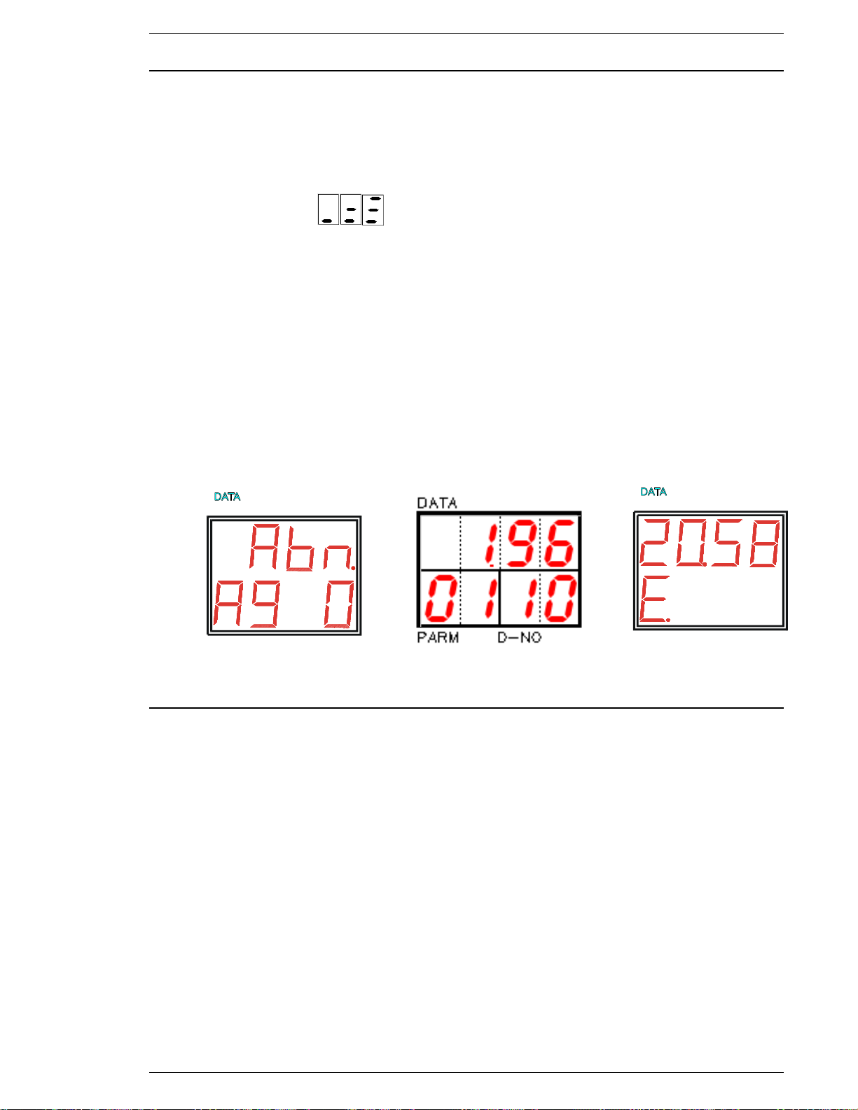
FEC Micro Nutrunner Operations Manual Chapter 7: System Operations (Rev. 2.1: 12/12)
D-NOPARM
D-NO
D-NOPARM
PARM
D-NO
PARM
7.1.2 Fastening Preset / Result displays.
w[D-NO] Data number indicator (2 digits).
Indicates the Display mode and data type (number)
・No digit: Status Display mode
・One digit: Real Time Display mode
・Two digits: Parameter Display mode
・Digit on the left : Fastening Result Display mode
When an Abnormal occurs the abnormal Sub Code will be displayed here.
w[DATA] Data value indicator (4 digits).
Displays the data specified by [D-NO] while in any display mode (refer to applicable section).
w[PARM] Parameter number/Abnormal number indicator (2 digits).
Display for the parameter number of the last fastening parameter run when in Fastening
Results Display mode, or the selected parameter when in Parameter Display or Setup mode.
Also displays an abnormal code during an abnormal condition. When the CAL switch is
pressed, "E" is shown if the FULL-SCALE preset value is missing or a wrong tool is
connected (Refer to Chapter 9).
Abnormal “A9” Display Parameter No. 1 Cal “E” Fault
Sub code “0” Data #10
7.1.3 Fastening Presetting / Result Display Controls.
wMODE button
PUsed to change modes. (Refer to 7.2)
PUsed to move the cursor while programming. (Refer to 7.3)
wSET button
PUsed to enter Data Edit mode and to confirm data setting changes.
w[] and [] Cursor push buttons (vertical arrows).
PUsed to scroll through available (8) parameter numbers. (PARM)
PUsed to scroll through available data preset items. (D-NO)
PUsed to change display data values. (DATA)
Used as YES/NO acknowledge for Tool type and Torque unit changes. (Fig 7-3-6)
Page 7-3
Page 72
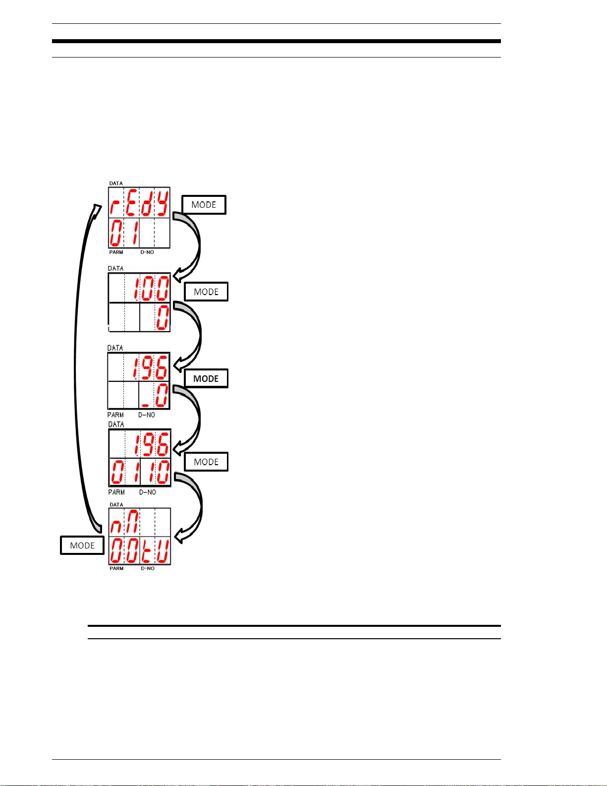
Chapter 7: System Operations
7.2 Display indication modes.
Five modes can be selected by pressing the MODE push-button. By using the [] and [] keys to
change the D-NO selected, the DATA display contents for parameters may be varied up or down.
The displays will remain blank and mode selection will be disabled while the nutrunner is active
(BUSY). If an Abnormal condition occurs, the display will automatically change to the Abnormal
(Abn) display mode displaying the abnormal code and sub-code.
While the MNR Unit is in cycle it will display the cycle status. The display will indicate where the
cycle is in its’ fastening sequence. Refer to section 7.2.1 for a listing of Status display
abbreviations
The MNR unit is in Status Display Mode when no digits
are displayed in the D-NO area of the display. The STATUS
display indicates when the system is ready to run, if an
abnormal condition occurs or if an emergency stop has
halted the system.
When the power is turned on the default display mode is
the Status display mode.
The Real Time Display Mode is active when only one digit
appears in the right hand location of the D-NO area of the
display. In this mode torque, angle, date and SD card
status will be shown. The display contents can be scrolled
through by using the [] and [] keys.
The Fastening Results Display Mode is active when the
D-NO displays one digit in the right hand location and one,
two or three dashes in the left hand location. The results
details can be scrolled through by using the [] and [] keys
to change the D-NO. This mode does not function while the
nutrunner is Busy.
The Parameter Display Mode is active when the D-NO
displays digits in both the right and left hand locations. The
parameter data can be scrolled through by using the [] and
[] keys to change D-NO.
The Torque unit, RS232C, SD setting. The display contents can be scrolled by using the [] and [] keys to
change.
FIG. 7-2 Display Modes
Page 7-4
Page 73
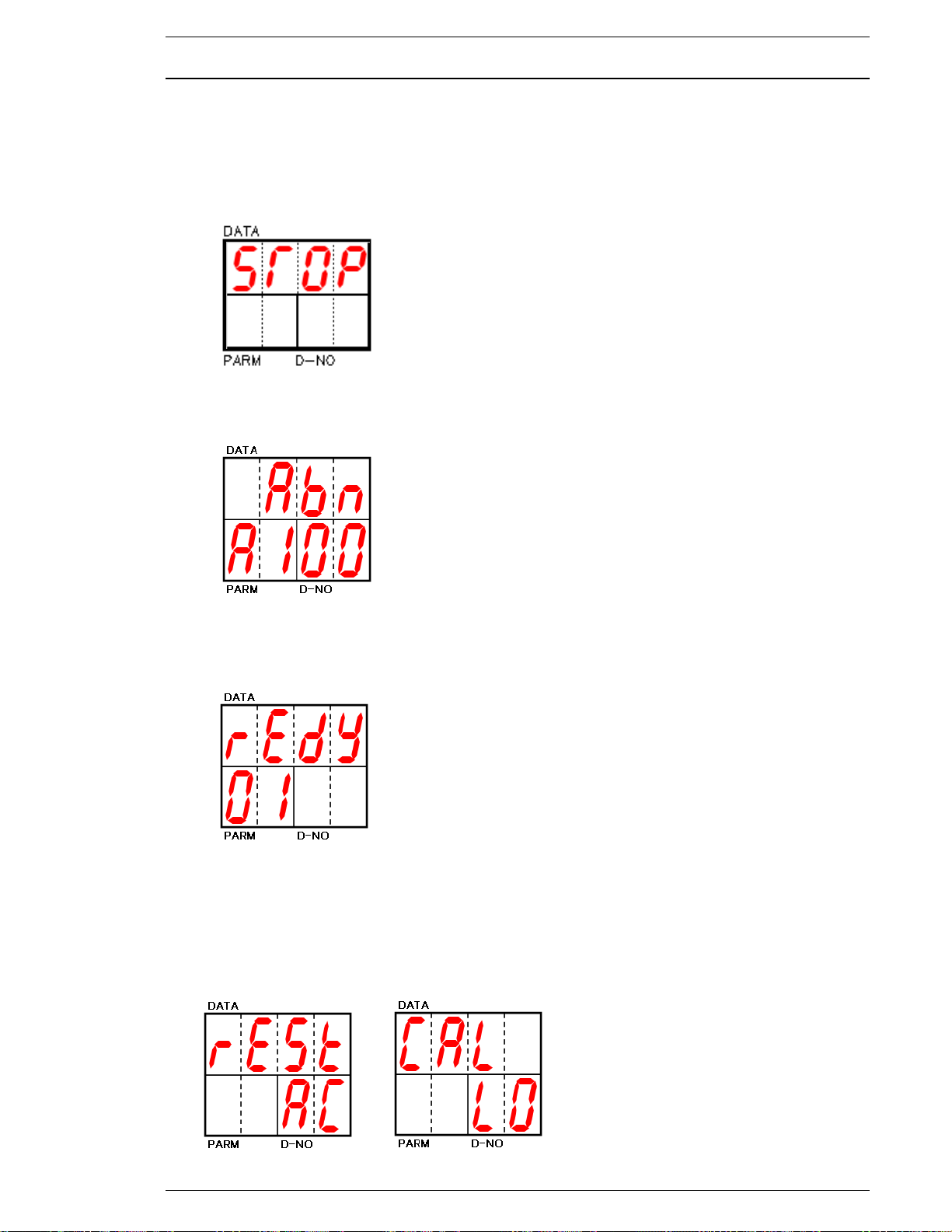
FEC Micro Nutrunner Operations Manual Chapter 7: System Operations (Rev. 2.1: 12/12)
7.2.1 STATUS display
Non-fastening Status display
Various types of non-Fastening Results STATUS can be displayed.
1) When the STOP signal is activated (signal goes low):
The DATA display will indicate when the STOP signal has halted the MNR Unit as shown in the
figure.
2) When an ABNORMAL condition occurs the [PARM] display will show a flashing "A" character
followed by a number that represents the Abnormal number code. The [D-NO] displays a number
that represents the SERVICE CODE NUMBER or SUB Code. (Refer to chapter 9)
3) When the system is Ready for operation the DATA display will show the characters “rEdY. This
signifies that the system is idle and ready or capable of receiving an input signal from external
equipment (IE: PLC, Switch box, etc.). The active parameter number will be shown in the [PARM]
display.
4) When the RESET pushbutton is pressed the DATA display will show the characters “rESt”. The
I/O will be reset and a Zero Level Check will be performed and the results will be displayed in the
[D-NO] area. When the CAL pushbutton is pressed the DATA display will show the characters
“CAL”. A CAL Check will be performed and the results will be displayed in the [D-NO] area.
■ Reset signal received ■ CAL check
Zero Level Accepted LOW Reject
Page 7-5
Page 74
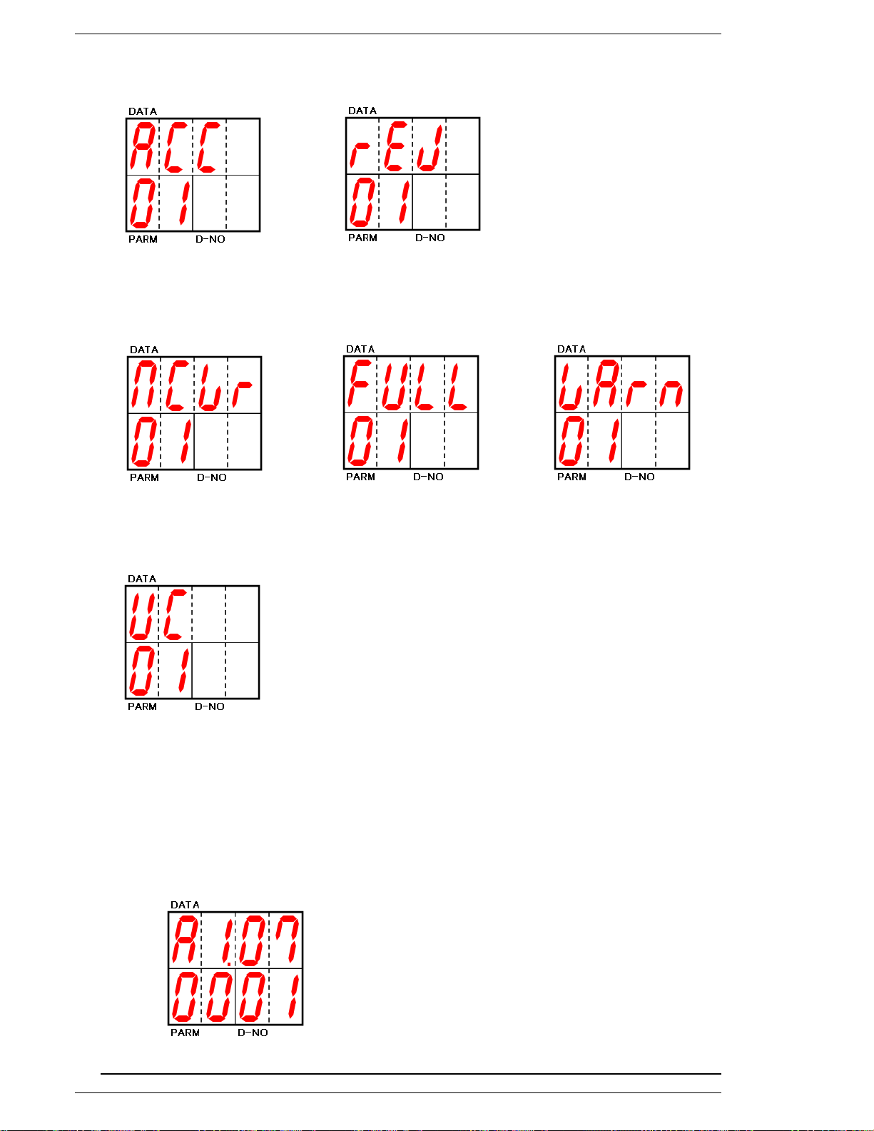
Chapter 7: System Operations
5) At the end of the fastening cycle the results will be displayed.
■ Fastening Accepted ■ Fastening Rejected
6) If a memory card is installed for saving cycle data, the status of the card will be displayed
alternatively between the fastening cycle results display or ready display.
■ Memory card writing ■ Memory card Full ■ Memory card
space warning
7) When the system is communicating with the User Console computer (Upload, Download, etc.),
the following will be displayed.
■ UC communication
Version display
Use [] and [] keys to change to the Firmware Version Display mode during while in the
Status Display mode.
The controller firmware version will be displayed in the [DATA] portion of the display. The
lower [PARM] & [D-NO] portion will display the servo amp version Lower portion displayed
servo amp firmware version.
Example showing controller firmware version A1.07 and servo amp firmware version 0001
Page 7-6
Page 75
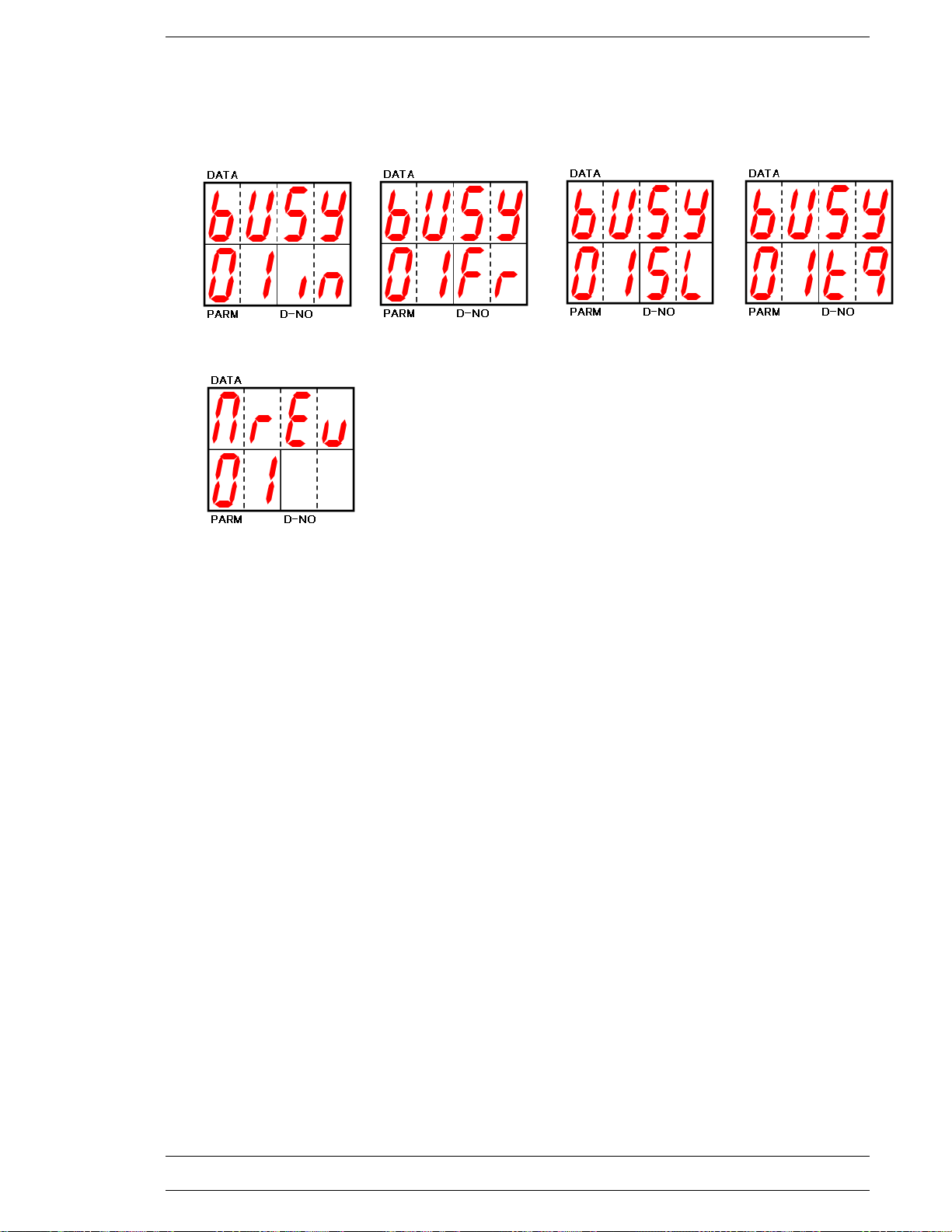
FEC Micro Nutrunner Operations Manual Chapter 7: System Operations (Rev. 2.1: 12/12)
Fastening Status display
The following example values are displayed during fastening operations using Parameter No. 1
■ During Initial ■ During Freerun ■ During Slowdown ■ During Torque
Speed Speed Speed Speed
■ Reverse signal received
Page 7-7
Page 76
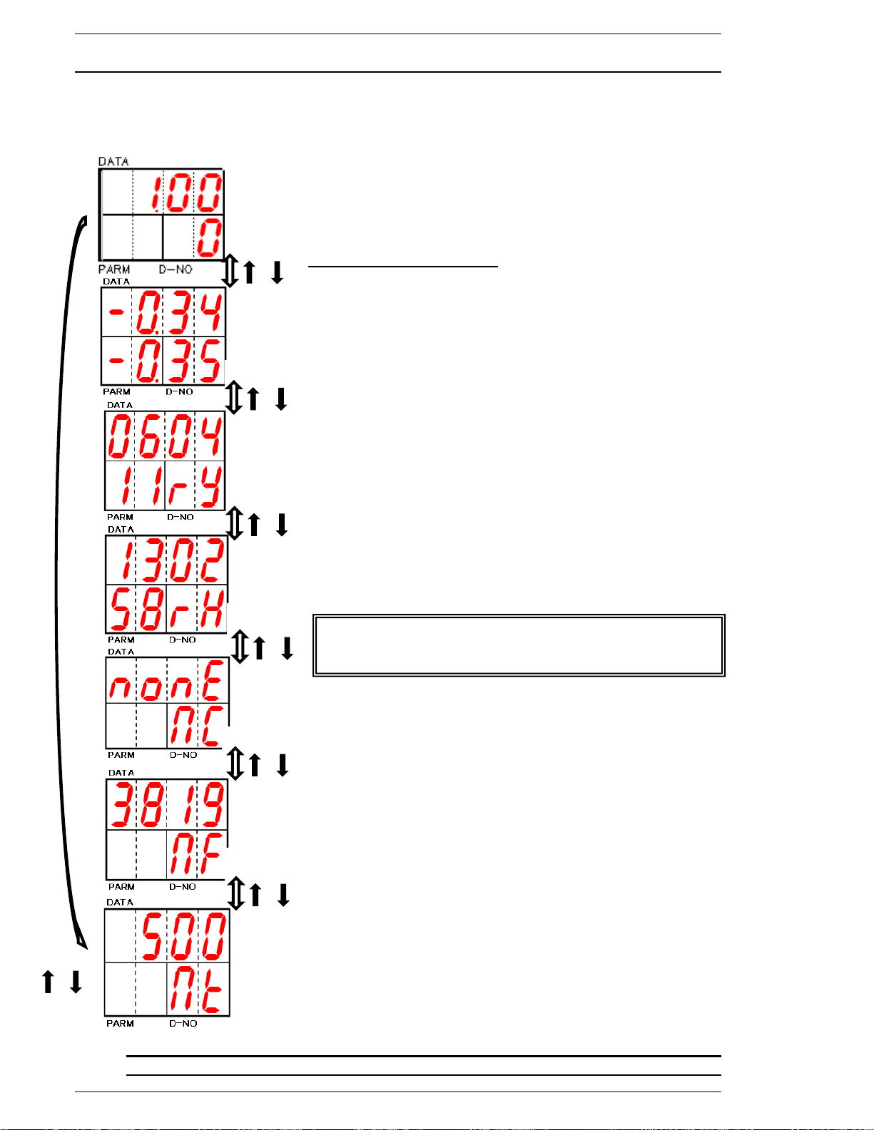
Chapter 7: System Operations
PRESS
or
or
PRESS
or
PRESS
or
PRESS
or
PRESS
or
PRESS
or
The Unit's RTC (Real Time Clock) data is held by
batteries. If date data is lost after powering down, check
for low battery.
7.2.2 Real Time Display mode.
While in the Real Time Display mode, you can choose the desired type of data by pressing the []
and [] keys. The indicator will display the following data in the [DATA] area and [PAR] / [D-NO]
display area.
Torque value: The real-time torque value from the torque
transducer is displayed in the [DATA] area.
Angle (rotation): The real-time angle of rotation of the tool
output shaft (in the CW fastening direction) measured since the
last time the display mode was switched to Real Time Display
Mode (-1999 to 9999) in shown in [PARM] / [D-NO].
NOTE: Motor Lock Function – Activated when [SET] is pressed
during this display. (See Motor Lock Function on the following
page.)
Torque voltage: The real-time torque signal voltage from the
torque transducer is displayed in the [DATA] area.
Transducer Zero Voltage: Torque transducer origin voltage
from the torque transducer is displayed in [PARM] / [D-NO].
Month / Date: Displays Month and Date data stored in Unit.
Example: “0604” for Jun 4th
Year: Displays two digits of the year in the [PARM] area.
Example: “11” for 2011
Hour / Minute: Displays Hour and Minute data stored in the Unit
(24 hour clock format) in the [DATA] area.
Example: “1302 for 1:02PM
Second: Displays Seconds data stored in the Unit in the
[PARM] area.
Example: “58” for 58 seconds
Memory card (SD) status: Displays memory card status.
Detailed information refer to detail section.
Memory card (SD) empty sectors: Display memory card empty
sectors in 1K sector units. New 2GB memory card (currently not
used) is 3819 K sectors.
Example: 3819 = 3,819 K-sectors
(1K Sector = 524,288 bytes)
Memory card (SD) writing time: Display memory card fastening
data writing time. Displayed in milliseconds (“0” is displayed
when not writing).
Example: 500 = 500 msec.
FIG. 7-2-2 Real-time Display selection
Page 7-8
Page 77
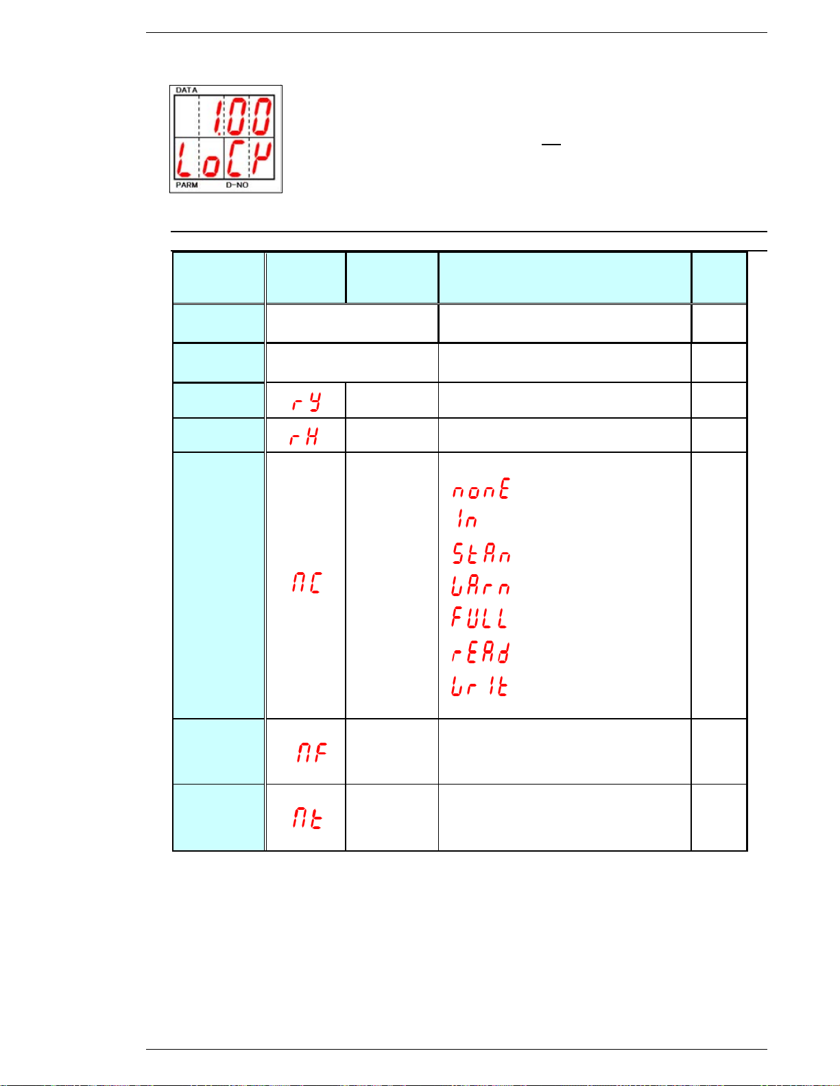
FEC Micro Nutrunner Operations Manual Chapter 7: System Operations (Rev. 2.1: 12/12)
Item
DATA
NUMBER
[D-NO]
PARAMETER
[PARM]
DATA
Torque/
Angle
Rotation angle[deg]
Torque [Nm/Kgm/Kgcm/Ftlb/Inlb]
Torque V
/Origin V
Origin Voltage [V]
Torque Voltage[V]
DATE
Year low
2 digit
Month - Date
TIME
Second
Hour - Minute
Memory card
drive status
:Not installed
:Installed
:Ready
:Warning
:Card full (No space)
:Reading
:Writing
Memory card
empty sectors
The number of memory card empty
sectors[K]
Memory card
fastening da-
ta writing time
Memory card fastening data writing
time[msec]
Motor Lock Function
When [SET] is pressed during the Torque/Angle display, the motor is locked
for up to one minute allowing the spindle to be checked with a torque wrench
while displaying the reaction torque. Press RESET to unlock the Motor before
one minute has expired. WARNING: Do not repeat this procedure repetitively
or the motor will overheat.
Real time display mode list
Page 7-9
Page 78
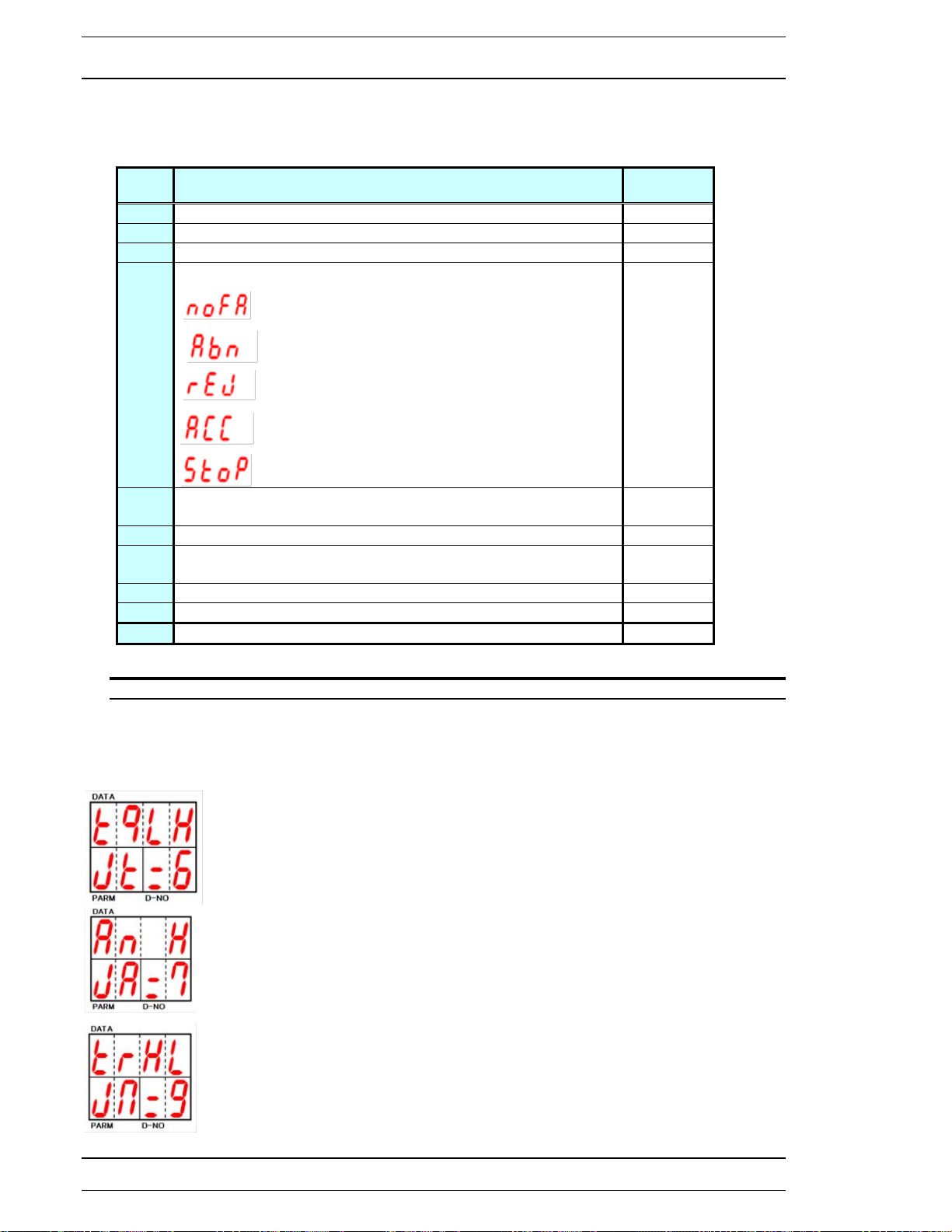
Chapter 7: System Operations
D-NO
DATA
Unit
_0
Peak Torque Value (Judgment torque value)
* Nm
_1
Final Angle Value
deg
_5
Cycle Time
Sec
=5
Cause of Fastening stop
No data /Reversed
Abnormal
Reject
Accept
Stop
=6
Torque final Judgment (Left digit) tq H/L
Torque peak Judgment (Right digit) tq H/L
See below
=7
Angle Judgment An H/L
See below
=9
Time Judgment (Left digit) ti H/L
Rundown revolution (Right digit) ti H/L
See below
4
Final Torque Value
* Nm
6
Maximum Current value
A
Rundown revolution
# of Rev
7.2.3 Fastening Results Display Mode.
In Fastening Results Display mode, when [D-NO] shows _0 ~ ), data can be obtained by
pressing the [] and [] keys to scroll the [D-NO] until the desired DATA item is displayed. The
following information will be displayed in the [DATA] display section for the displayed [D-NO]:
* Unit of measure for Torque can be Nm, Kgm, Kgcm, Ftlb or Inlb
FIG. 7-2-3 Fastening results display selection
Judgment display
On items where a judgment is displayed (=6, =7 & =9), the judgment (H or L) will be displayed in the
right most 2 digits of the DATA display.
Final Torque (left digit) / Peak Torque (right digit) judgment.
Judgment display showing Final Torque Low (L) and Peak Torque High (H).
Angle judgment
Judgment display showing Angle High (H).
Time (left digit) / Rundown Revolutions (right digit) judgment.
Judgment display showing Time High (H) and Rundown Revolutions Low (L).
Page 7-10
Page 79
FEC Micro Nutrunner Operations Manual Chapter 7: System Operations (Rev. 2.1: 12/12)
Parameter No.8
Parameter No.7
Parameter No.6
Parameter No.03
Parameter No.02
Parameter No.01
69: Rundown revolution High
~
7.2.4 Parameter Display Mode
Parameter Display mode displays the preset values programmed in the MNR unit for the
fastening operation. The MNR system can store up to 8 different sets of parameters that can be
selected by input signals WORK SELECT 0 ~ 2 (see section 4.7.2.).
Note: Representation only, not actual data.
The data displayed in this section is the DISPLAY only for the Configured Parameters.
See Section 7.3 for information on how to change these values.
10: Calibration torque
11: Peak Low Torque
12: Peak High Torque
13: Standard Torque
68: Rundown revolution Low
FIG. 7-2-4a Parameter number selection
Page 7-11
Page 80
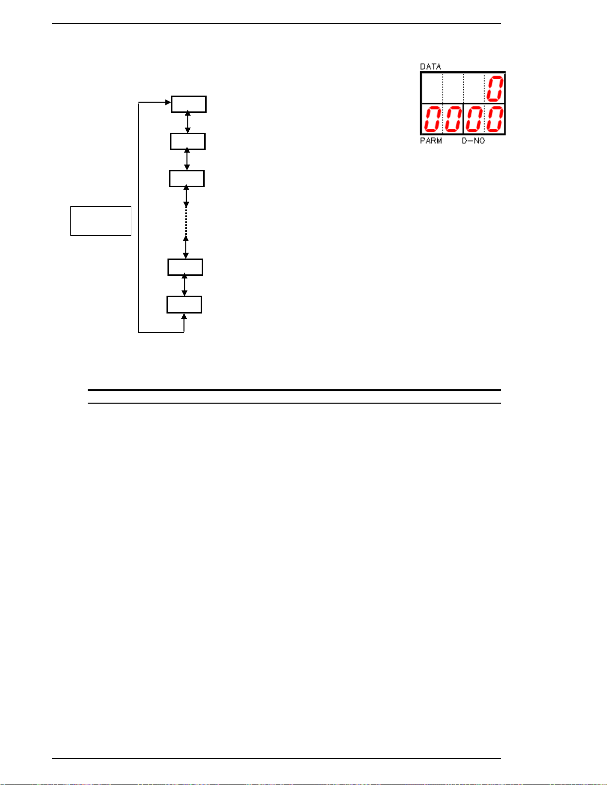
Chapter 7: System Operations
10
[] []
keys
11
12
68
69
~
「D-NO」 「PARM」 「DATA」
0 1 Calibration Torque (CAL value)
0 1 Peak Low Torque Limit
0 1 Peak High Torque Limit
0 8 Rundown Revolution Low Limit
0 8 Rundown Revolution High Limit
Last data of PARAMETER 8
FIG. 7-2-4b Parameter display D-No selection
When Parameter Display mode is enabled, the [D-No] display will show 2 digits (10-69)
representing the preset data number. The [DATA] display will show the corresponding preset data
value and the parameter display [PARM] will indicate the parameter number (from 0 ~ 8). Use the
[] and [] keys to change the preset data number [D-NO]. If the [D-NO] display is showing the
number 69 of the parameter number 1, pressing the [] key will change the [D-NO] display to the
number 10 of the parameter number 2.
You can verify the fastening parameters by pressing the [] and [] keys at any time.
Page 7-12
Page 81
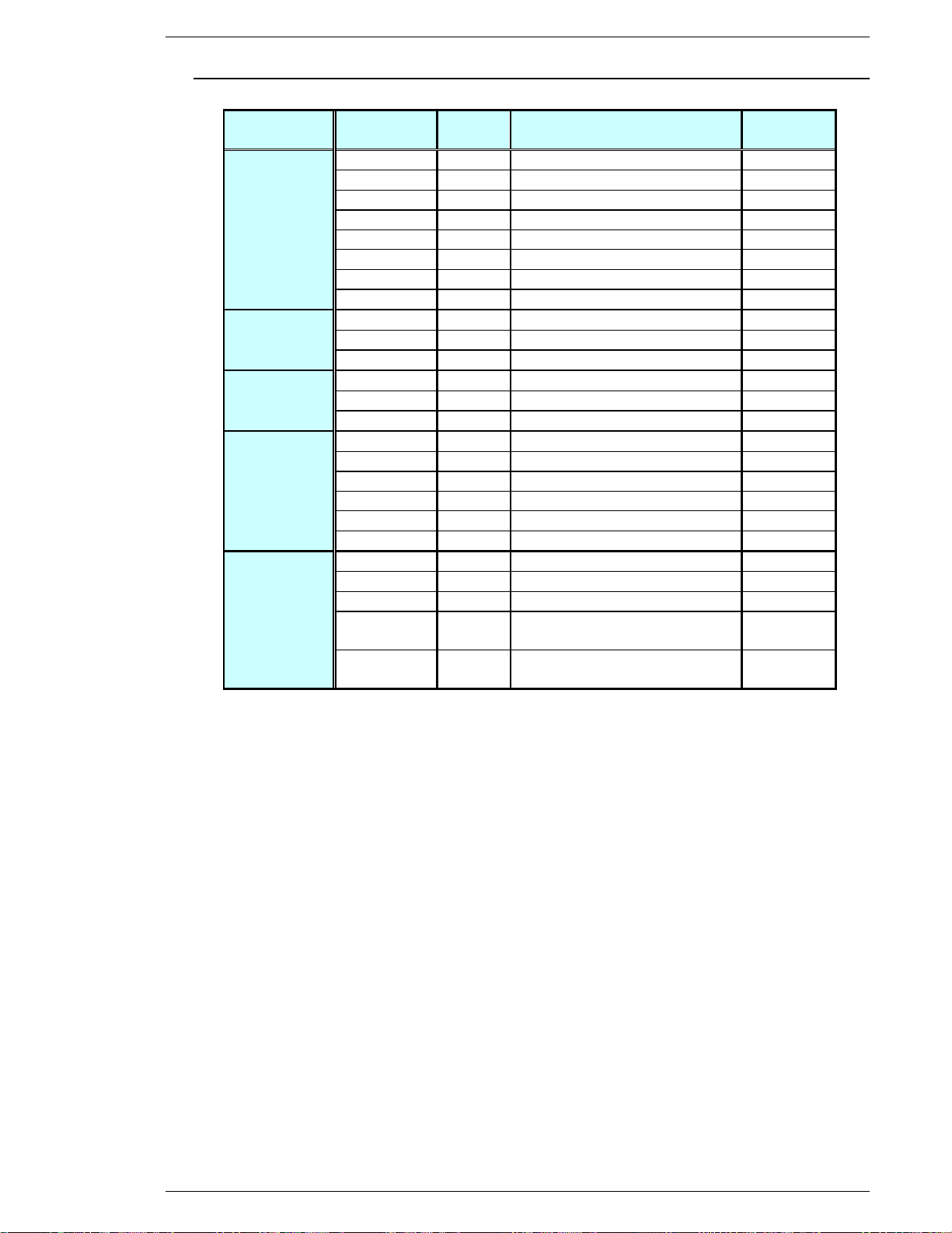
FEC Micro Nutrunner Operations Manual Chapter 7: System Operations (Rev. 2.1: 12/12)
Item
[Unit]
Parameter No.
PARM
Data No.
D-NO
DATA
Torque/Angle
Method
Torque
[Nm]
01~08
10
Calibration torque (CAL value)
○
01~08
11
Peak Torque Low Limit
○
01~08
12
Peak Torque High Limit
○
01~08
13
Standard Torque
○
01~08
14
Speed Change Torque
○
01~08
16
Snug Torque
○
01~08
19
Torque Inhibit Limit
○
01~08
1A
1 Pulse Reverse Torque Limit
○
Angle
[deg]
01~08
20
Angle Low Limit
○
01~08
21
Angle High Limit
○
01~08
22
Standard Angle
○
Time
[sec]
01~08
40
Initial Time
○
01~08
41
Freerun Time Limit
○
01~08
42
Fastening Time Limit
○
Rotation
Speed
[rpm]
01~08
50
Initial Speed
○
01~08
51
Freerun Speed
○
01~08
52
Slowdown Speed
○
01~08
53
Torque Speed
○
01~08
54
Reverse Speed
○
01~08
55
1 Pulse Reverse Speed
○
Revolutions
[rev]
01~08
60
Freerun Revolutions
○
01~08
61
Torque Inhibit Revolutions
○
01~08
64
1 Pulse Reverse Time
○
01~08
68
Rundown Revolutions
Low Limit
○
01~08
69
Rundown Revolutions
High Limit
○
7.2.5 Parameter Data List
Page 7-13
Page 82

Chapter 7: System Operations
The MNR system will fasten to Standard Torque or Standard Angle (WHICHEVER THE
SYSTEM SENSES FIRST). If fastening to Standard Torque, set Standard Angle at 9999
or high enough not to trigger a judgment for Standard Angle.
Data No.10 Calibration torque
The calibration value is set according to the tool type (capacity). However, depending on the
application characteristics or the prevailing torque generated external to the tool output shaft, the
value of the applied torque and the torque display by the SAN unit may mismatch. In this case it
is possible to adjust the FULL SCALE TORQUE (CAL) value so the displayed torque matches the
installation torque registered by an external torque transducer (Master).
The CAL value can be adjusted up to %of the FULL SCALE TORQUE value.
Example:
Consider the NFT-080M10-S tool. Nominal CAL value = 2.45 Nm.
Range of adjustment: from 2.94 Nm to 1.96 Nm.
Use the following formula on a collection of at least 10 fastenings when a calibration
correction is necessary:
New CAL value = Master transducer mean/ FEC transducer mean x Existing CAL value
Note: The torque unit (Kgm, Nm, Ft.Lbs, etc.) must be the same for all terms. Do not
mix torque units in calculation or errors will result.
If the new CAL value is out of the adjustable range, the [Err] message will be displayed.
Example.
Tool Full Scale value (EXISTING CAL) is 2.450 Nm.
STD torque is 0.3000 Nm.
Master transducer mean for 10 piece run is measuring 0.280 Nm.
FEC transducer mean for 10 piece run is measuring 0.3000 Nm.
The new CAL value is obtained as follows:
(0.280/0.300 x 2.450) = 2.287
The FULL SCALE TORQUE (CAL) value must be corrected to 2.287 Nm and
entered at [PARM] 1~8 [D-NO] 10.
Data No.11 Peak Torque Low Limit [Nm, Kgm...]
Data No.12 Peak Torque High Limit Nm, Kgm...]
Setting range: 0 ~ [10: Calibration torque] × 1.1
Setting points for the High and Low limits of the Peak Fastening Torque. If the High limit is
reached the fastening operation will stop even if the operation is not complete. Low limits are
reported at the end of the cycle.
When fastening to Standard Angle, Peak Torque Low Limit is also used for Final Torque
judgment. If the Final Torque is less than Peak Torque Low the judgment is Reject.
Data No.13 Standard Torque [Nm, Kgm...]
Setting range: 0 ~ [10: Calibration torque] × 1.0
Set point of the Fastening Standard (Target) Torque.
Page 7-14
Page 83
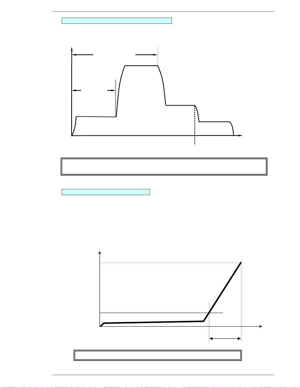
FEC Micro Nutrunner Operations Manual Chapter 7: System Operations (Rev. 2.1: 12/12)
41:Freerun time
Time/Revolution
Speed
50:Initial Speed
40:Initial Time
53:Torque Speed
14:Speed change torque
Even if [60: Freerun Revolutions] or [41: Freerun Time Limit] are not achieved, the
speed will change to Torque Speed when [14: Speed Change Torque is detected.
Torque
Angle
90°
Judgment torque
16 SNUG
0.01Nm
22 Standard Angle
All values related to Angles are referenced from [16: SNUG Torque]
Data No.14 Speed Change Torque [Nm, Kgm...]
Setting range: 0 ~ [10: Calibration torque] × 1.0
Set the torque value that switches slow down speed to torque speed.
or 60:Freerun Revolutions
51:Freerun Speed
52:Slow Down Speed
Data No.16 SNUG Torque [Nm, Kgm...]
Setting range: 0 ~ [10: Calibration torque] × 1.0
Snug Torque is the control start point when fastening to a Standard Angle.
Angle (of rotation) Judgment is conducted from Snug Torque to Fastening end when
this torque value is achieved. The Angle when this torque value is achieved is considered the 0° start point for judgment.
(Example) When [16: SNUG Torque] is 0.01Nm, [22: Standard Angle] is 90°.
Page 7-15
Page 84
Chapter 7: System Operations
The MNR system will fasten to Standard Torque or Standard Angle (WHICHEVER THE
SYSTEM SENSES FIRST). If fastening to Standard Angle, set Standard Torque equal to
the Calibration Torque of the tool or high enough not to trigger a judgment for
Standard Torque.
To use the 1 Pulse Reverse function [1A: 1P Reverse Torque], [55: 1P Reverse Speed]
and [64: 1P Reverse Time] must all be set up. If any one of these do not have a value
set, the 1 Pulse Reverse function will be disabled.
Data No.19 Torque Inhibit Limit [Nm, Kgm...]
Setting range: 0 ~ [10: Calibration torque] × 1.1
Limit for ignoring the Torque value sensed during fastening start due to inertia. When the initial
Torque exceeds the Torque Inhibit Limit during [61: Torque Inhibit Revolutions] an ABNORMAL
will be generated and fastening will end.
Data No.1A 1P Reverse Torque [Nm, Kgm...]
Setting range: 0 ~ [10: Calibration torque] × 1.1
Maximum torque value that will be applied to the fastener in reverse when using the 1 Pulse
Reverse function.
Used to disengage the socket from the fastener when a locking condition can occur.
Data No.20 Low Angle [deg]
Data No.21 High Angle [deg]
Setting range: 0~9999
Sets the High and Low limits for Fastening Judgment Angle as measured from [16: SNUG
Torque] to Fastening End. If the High limit is reached the fastening operation will stop even if the
operation is not complete. Low limits are reported at the end of the cycle.
Data No.22 Standard Angle [deg]
Setting range: 0~9999
Sets the target Angle value for fastening as measured from [16: SNUG Torque].
Data No.40 Initial Time [sec]
Setting range: 0 ~ 999.9
During initial time, the start of the fastening operation will be conducted at [50: Initial Speed].
When [40: Initial Time] is set as 0, the operation will start at [51: Freerun Speed].
Data No.41 Freerun Time Limit [sec]
Setting range: 0~999.9
Sets the maximum time the system will run at [51: Freerun Speed].
Data No.42 Fastening Time Limit [sec]
Setting range: 0~999.9
Set the high time limit from beginning of the operation to fastening end.
If this time elapses before reaching the target, the process is rejected.
Data No.50 Initial Speed [rpm]
Setting range: Tool’s minimum rpm ~ Tool’s maximum rpm
Sets the speed at which the tool will begin operations. Slower speeds are used to aid in fastener
engagement.
Data No.51 Freerun Speed [rpm]
Setting range: 1 ~ Tool’s maximum rpm
Sets the high speed rundown value used to drive a fastener to seating. Shifts to [52: Slow
Down Speed] when [41: Freerun Time Limit] or [60: Freerun Revolutions] is sensed.
Page 7-16
Page 85
FEC Micro Nutrunner Operations Manual Chapter 7: System Operations (Rev. 2.1: 12/12)
To use the 1 Pulse Reverse function [1A: 1P Reverse Torque], [55: 1P Reverse Speed]
and [64: 1P Reverse Time] must all be set up. If any one of these do not have a value
set, the 1 Pulse Reverse function will be disabled.
To use the 1 Pulse Reverse function [1A: 1P Reverse Torque], [55: 1P Reverse Speed]
and [64: 1P Reverse Time] must all be set up. If any one of these do not have a value
set, the 1 Pulse Reverse function will be disabled.
Data No.52 Slow Down Speed [rpm]
Setting range: 1 ~ Tool’s maximum rpm
Sets the speed used to draw the fastener down to [14: Speed Change Torque].
When [14: Speed Change Torque] is sensed the operation will switch to [53: Torque
Speed]
Data No.53 Torque Speed [rpm]
Setting range: 1 ~ Tool’s maximum rpm
Sets the speed during final fastening operation.
*Slower torque speed results in better fastening accuracy.
Data No.54 Reverse Speed [rpm]
Setting range: 1 ~ Tool’s maximum rpm
Reverse operates when the manual reverse input is selected.
Data No.55 1P Reverse Speed [rpm]
Setting range: 1 ~ Tool’s maximum rpm
Speed value that will be applied to the fastener in reverse when using the 1 Pulse
Reverse function.
Data No.60 Freerun Revolutions [rev]
Setting range: 0 ~ 99.9
Sets the number of revolutions the system will run from the beginning of the fastening operation
until [51:Freerun Speed] is no longer needed.
Data No.61 Torque Inhibit Revolutions [rev]
Setting range: 0 ~ 99.9
For operation that require large starting torque.
Duration for ignoring the Torque value sensed at Fastening start due to inertia. When the initial
Torque exceeds the [19: Torque Inhibit Limit] during [61: Torque Inhibit Revolutions] an
ABNORMAL will be generated and fastening will end.
Data No.64 1Pulse Reverse Time [sec]
Setting range: 0 ~ 99.9
Time value that will be applied to the fastener in reverse when using the 1 Pulse reverse function.
The reverse operation will be maintained for as long as the time is set for.
Data No.68 Rundown Revolutions Low Limit [rev]
Data No.69 Rundown Revolutions High Limit [rev]
Setting range: 0 ~ 99.9
Low and High limits used to detect if a fastener seated too early or too late during the rundown.
Used to detect incorrect fastener lengths or threaded hole depths.
Page 7-17
Page 86
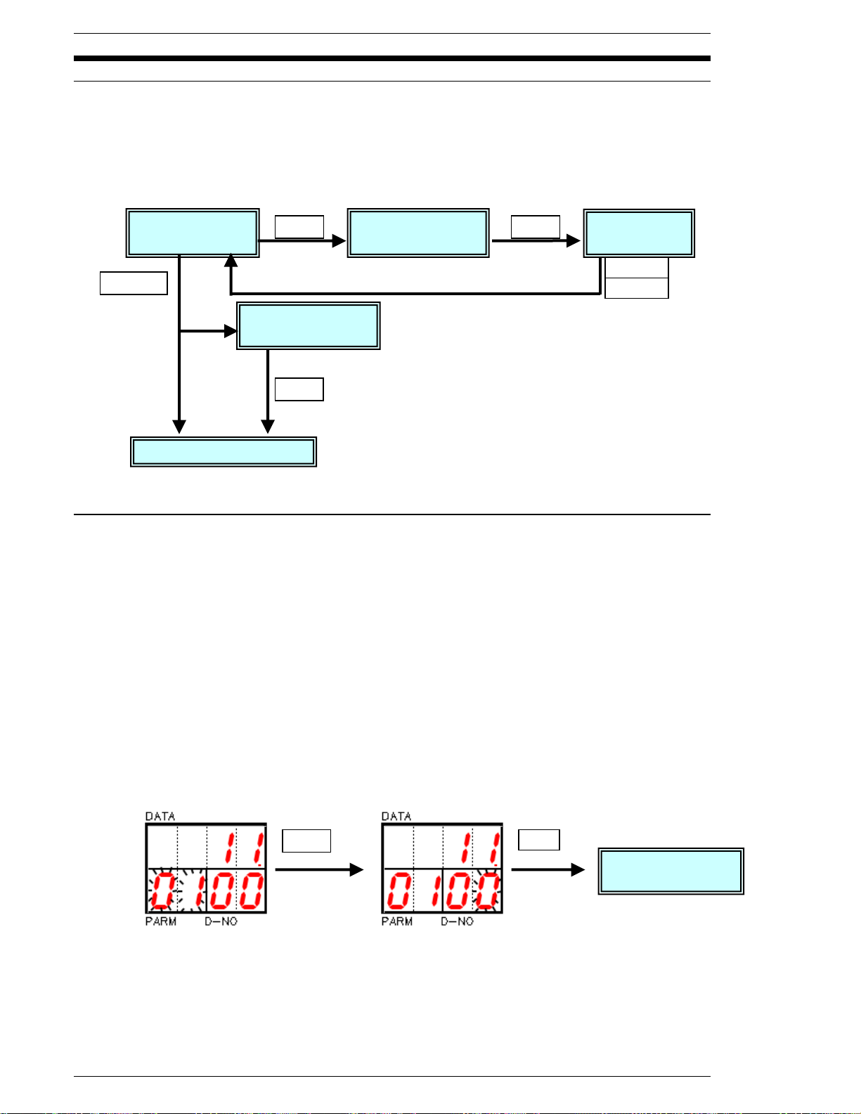
Chapter 7: System Operations
Parameter
Display Mode
Parameter
Select Mode
Data Edit
Mode
Parameter Edit
Confirmation [Y/N]
RS-232c Display Mode
SET
SET
SET
MODE
MODE
SET
SET
Parameter Edit
Operation
SET
7.3 Parameter Display, Select (setup) and Data Edit Operation
All 8 Parameter sets can be setup using the programmer. Press the [MODE] button to select the
Parameter Display mode. Use [] and [] keys to select the desired parameter.
Downloading via the MNR Software can be accomplished anytime the unit is in the Ready State.
This is accomplished by the software, which disables the nutrunner operation during
programming.
Cursor
Enter
Displayed when parameter data is modified at edit
mode.
Parameter will not update without confirmation.
7.3.1 Parameter Select (setup) Mode
Press the [SET] buttons to initiate the Parameter Select mode. Immediately after the select mode
is initiated, a blinking number will appear in the [PARM] display.
When the cursor is in the [PARM] display, the settings can be changed from 01 ~ 08 with the
[] and [] keys. Data corresponding to the selected parameter number will be displayed in the
[DATA] display.
The cursor (blinking digits) will move to the next character to the right in [D-NO] after the [SET]
button is pressed.
Use [] and [] buttons to select the desired Data number.
The [DATA] characters will display the actual value of the [D-NO] as it is currently set.
Press the [SET] button to enter into the Data Edit mode on the indicated D-NO. you want to
change. (See 7.3.3 for detail)
The preset values are not arranged in a perfect sequence and some numbers may be skipped.
When scrolling the DATA numbers, it will scroll to the next existing value in the same or the
following parameter number.
Parameter Select Data Number Select
Page 7-18
Page 87
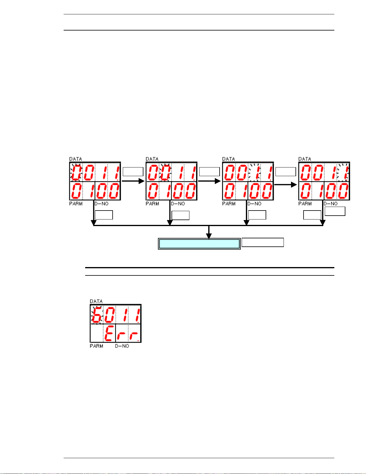
FEC Micro Nutrunner Operations Manual Chapter 7: System Operations (Rev. 2.1: 12/12)
MODE
MODE
MODE
SET
① ② ③
④
Parameter display mode
SET
SET
SET
MODE
7.3.2 Data Edit Mode
After you have selected the Parameter number and the Data number you would like to edit, press
the [SET] button to enter the Data Edit mode.
The blinking digit will now appear at the left digit of the [DATA] field. You can move one digit to
the right each time you press the [MODE] button. By pressing the button four times, you leave the
Data Edit mode and return to the Setup mode (without saving any changes). Use the [] and []
buttons to increase or decrease the digit that is blinking.
After changes have been made, pressing the [SET] button will return you to the Parameter
Display mode.
If the entered values are out of range / limits, "Err" will appear, and the new data will be ignored.
In this case, return to the parameter number selection (using the [MODE] key) and enter data that
is acceptable.
NOTE: Data will not store until the confirmation [Y or N] process has been completed.
FIG. 7-3-2 Setup mode operation
Page 7-19
Page 88
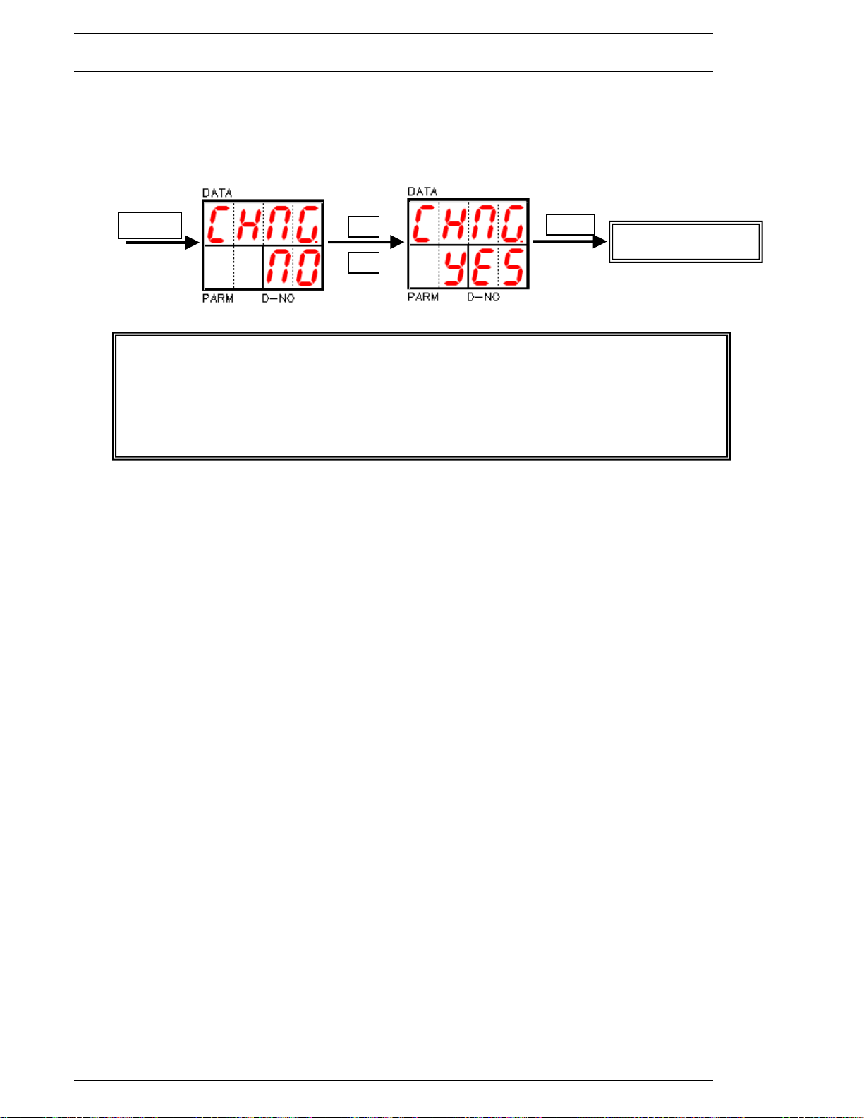
Chapter 7: System Operations
If neither “Yes” nor “No” is selected within 4 seconds, the new data will be ignored and
the system will exit the Data Edit Mode.
If the [MODE] button is pressed when the cursor (blinking digit) is at the right-most digit
in the [DATA] display, the new data will be ignored and the system will exit the Data Edit
mode.
If Power is turned off to the system while in Data Edit Mode, the new data will not be
stored.
MODE
SET
Parameter update
7.3.3 Parameter Setup Confirmation
When the data is changed, the [DATA] display will show "CHNG," and the D-NO display will show
"NO." Use the vertical arrow buttons to choose YES or NO; YES means that the data will be
entered if the confirmation SET button is pressed. The [SET] and [MODE] buttons will have no
effect when "NO" appears.
Page 7-20
Page 89
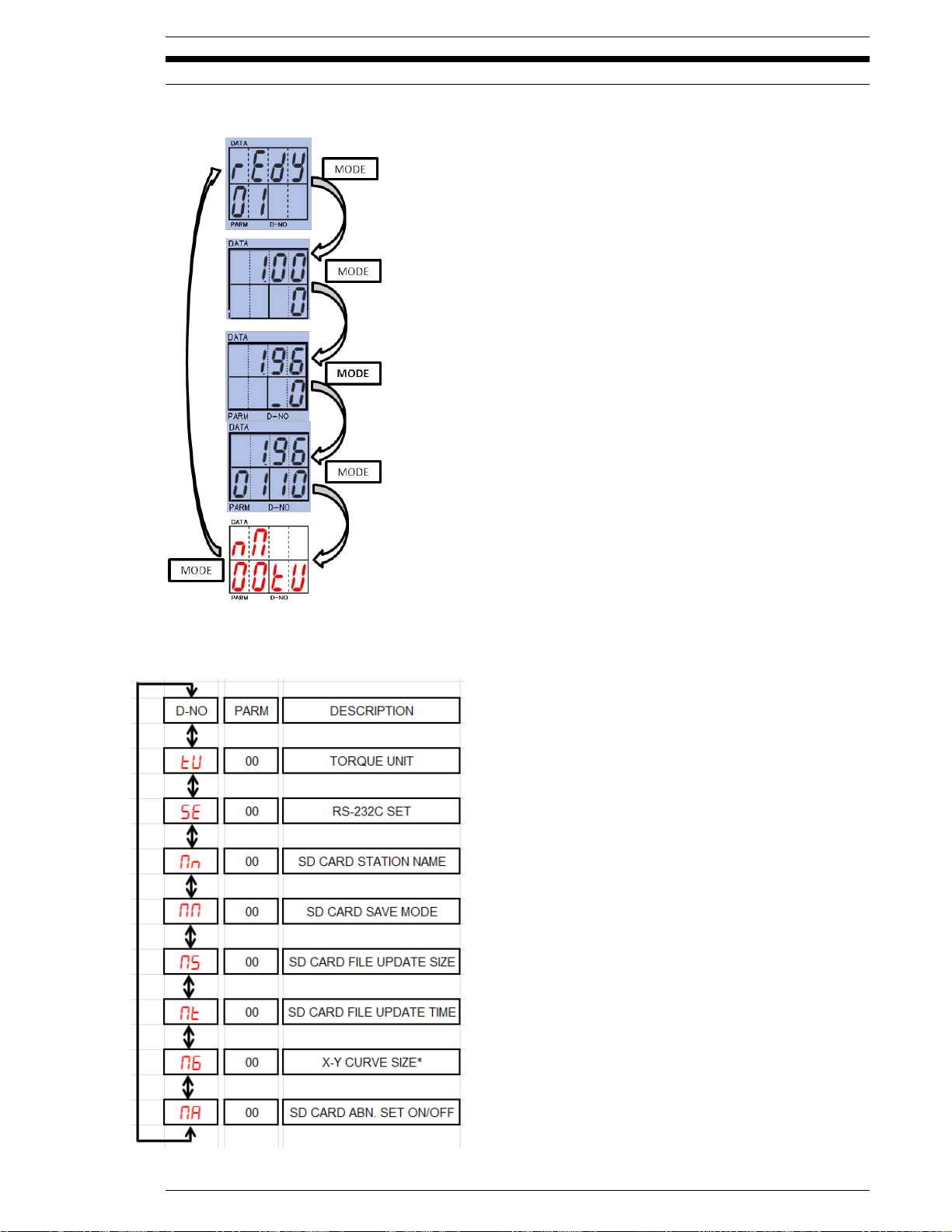
FEC Micro Nutrunner Operations Manual Chapter 7: System Operations (Rev. 2.1: 12/12)
(Section 7.4.1)
(Section 7.4.2)
(Section 7.4.3)
(Section 7.4.4)
(Section 7.4.5)
(Section 7.4.6)
(Section 7.4.6.1) *Appears when SW1-8 is “ON”
(Section 7.4.7)
7.4 Torque Unit / RS232C / Memory Card Display Mode
Press the [MODE] button to select TORQUE UNIT/RS232C/MEMORY CARD Display mode.
STATUS Display mode
REAL TIME Display mode
RESULT DATA Display mode
PARAMETER DATA Display mode
TORQUE UNIT/RS232C/MEMORY CARD Display mode
Select the desired preset menu by using the [] and [] buttons.
Page 7-21
Page 90
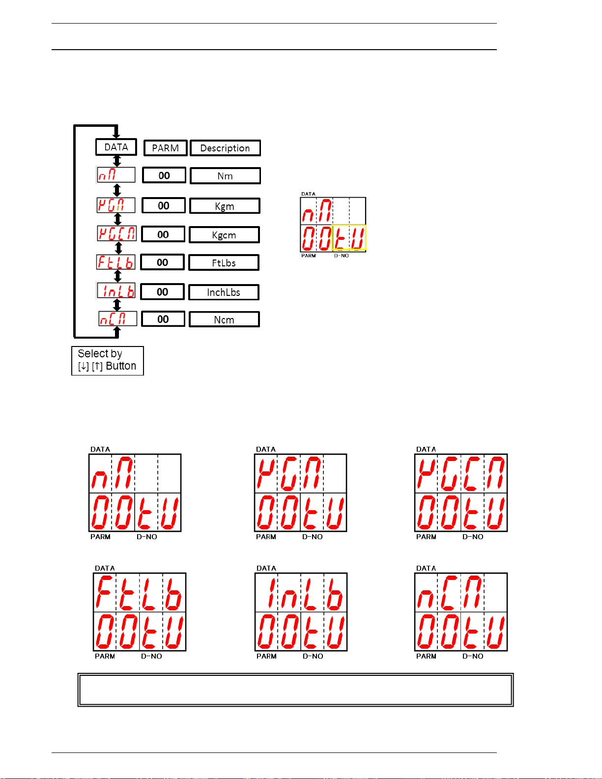
Chapter 7: System Operations
When the Torque Unit parameter is changed, all fastening parameters (01 ~ 08) are
cleared. All parameter data must be re-entered and verified after changing this parameter.
7.4.1 Torque Unit Display / Edit Mode
Pressing the [SET] button will initiate the preset edit mode and a blinking data will appear in the
[DATA] display.
The blinking character can be changed (selected) by using the [] and [] buttons.
Note: All parameters will be changed to the selected torque unit.
Torque unit selection:
Nm Kgm Kgcm
Ft lbs Inch lbs Ncm
Page 7-22
Page 91
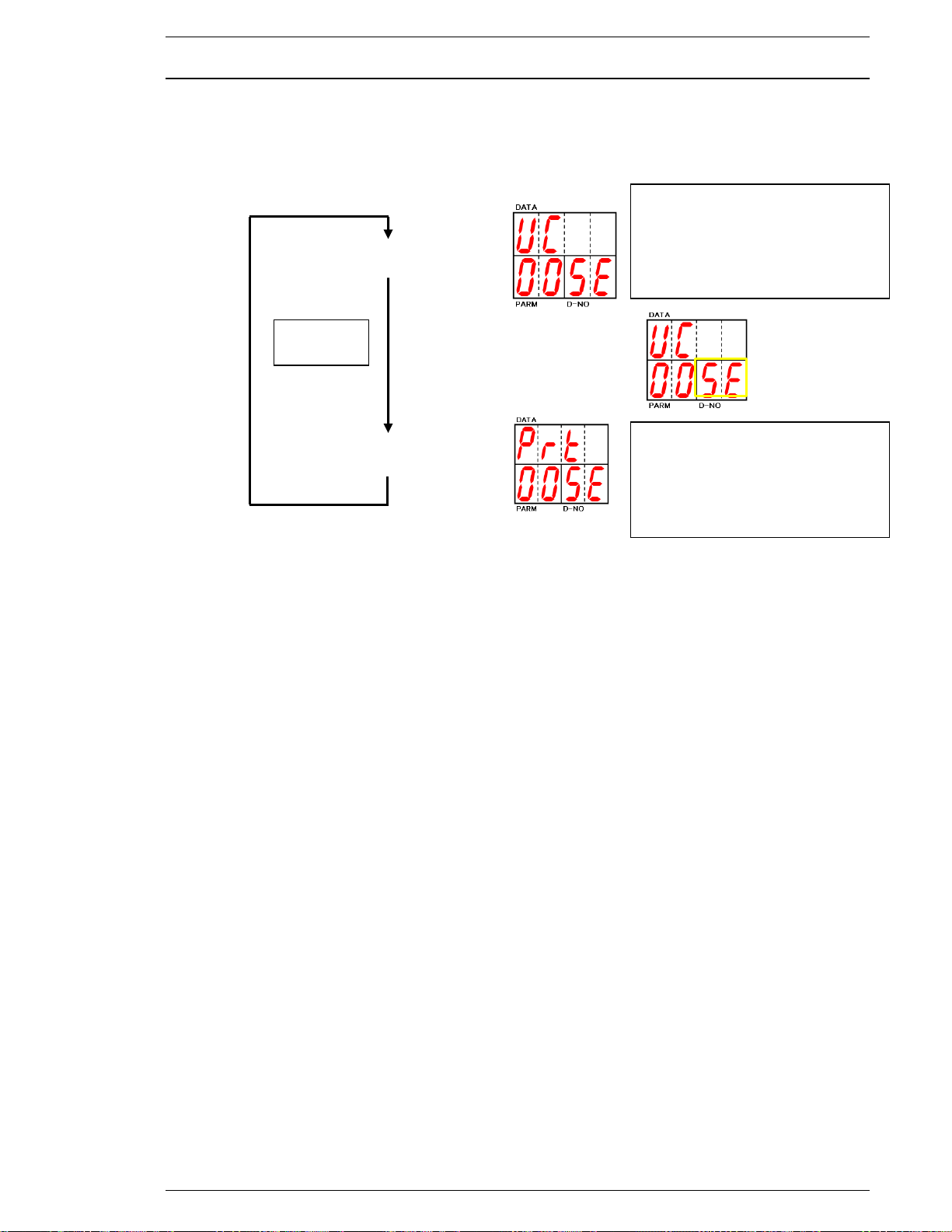
FEC Micro Nutrunner Operations Manual Chapter 7: System Operations (Rev. 2.1: 12/12)
[], []
Button
Set to “UC” to enable User
Console software communication
through the RS232 port.
This setting disables User Console
communication through the USB
port.
Set to “Prt” to enable data output
to an external device (IE: printer,
PLC, etc.) through the RS232 port.
This setting enables User Console
communication through the USB
port.
7.4.2 RS232C Display / Edit Mode
Select RS-232c port either Printer or User-console mode.
Depressing the SET button will initiate the preset edit mode and a blinking data will appear in the
[DATA] display. The blinking character can be change (select) by using the [] and [] buttons.
This operation requiring Data confirmation and Power off and on cycle. (Check detail section)
User-console mode
Fastening data output mode
Select Fastening data output mode when using USB User-Console communication.
Page 7-23
Page 92
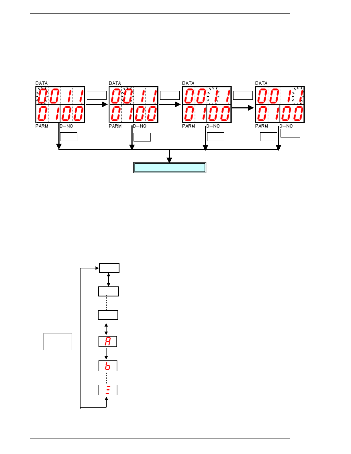
Chapter 7: System Operations
MODE
MODE
MODE
SET
① ② ③
④
Preset display mode
SET
SET
SET
MODE
0
[][]
button
1
9
7.4.3 Memory Card Station Name Display / Edit mode
After enter [PESET EDIT MODE], the blinking digit will appear at the [DATA ①] field.
Use [] and [] buttons to increase or decrease data at blinking digit.
Press [MODE] button to move blinking cursor [DATA ①]→ [DATA ②]→[DATA ③]→
[DATA ④] and state change to [PRESET DISPLAY MODE].
After changes have been made, pressing the [SET] button will save the changes and exit to the
Preset display mode.
Numerical and Alphabetical data characters can be select as follows.
Use appendix data list to select actual data.
Use [] and [] buttons to identify front / back character.
Numerical and Alphabetical data character change as follow.
Use appendix data list to select actual data.
Use [] and [] buttons to identify front / back character.
Refer Appendix data information.
Default data is “STO1”
When the system uses multiple stations, use each station under different name.
Use []/[] buttons to create a new station name when no information is found.
Page 7-24
Page 93
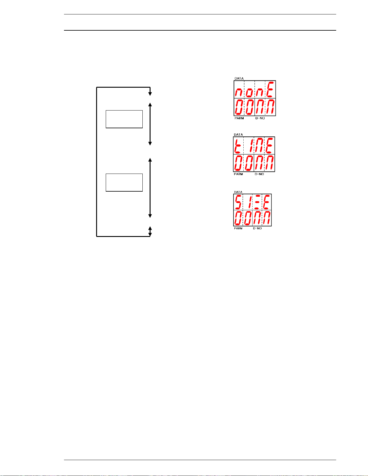
FEC Micro Nutrunner Operations Manual Chapter 7: System Operations (Rev. 2.1: 12/12)
[] []
buttons
[] []
buttons
7.4.4 Memory Card Data Save Display / Edit mode
After enter [PESET EDIT MODE], the blinking data will appear at the [DATA] field.
Use [] and [] buttons to select desire preset.
The data (Fastening data, Torque signature) will not store on memory card if save is not selected.
Not saved on memory card.
Update file by Time stamp
Update file by file size
Following confirmations are important to execute function as desired.
Update file by time stamp: Confirm preset time data for update.
Update file by file size: Confirm preset file size
Preset and confirm MNR controller time and date information by using User-Console software.
Page 7-25
Page 94
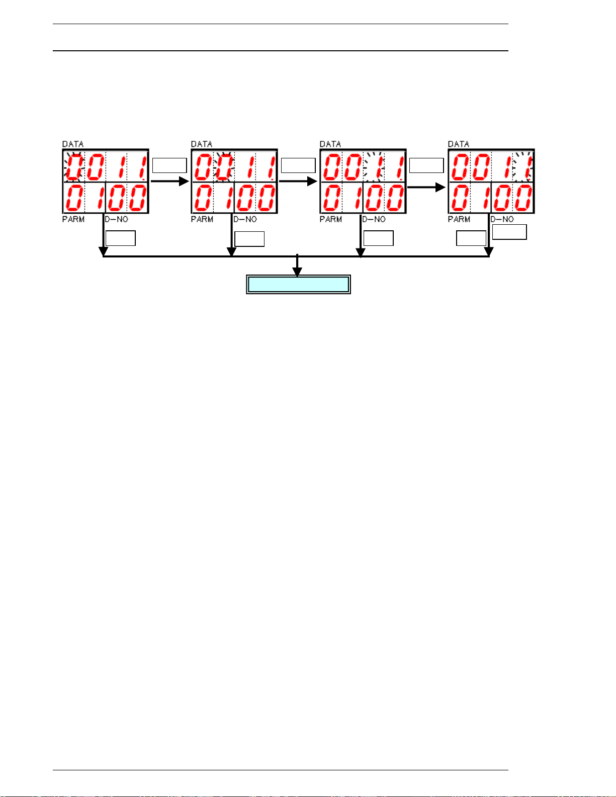
Chapter 7: System Operations
MODE
MODE
MODE
SET
① ② ③
④
Preset display
SET
SET
SET
MODE
7.4.5 Memory Card Data File Update by Size Display / Edit mode
After enter [PESET EDIT MODE], the blinking digit will appear at the [DATA ①] field.
Use [] and [] buttons to increase or decrease data at blinking digit.
Press [MODE] button to move blinking cursor [DATA ①]→[DATA ②]→[DATA ③]→
[DATA ④]and state change to [PRESET DISPLAY MODE].
After changes have been made, pressing the [SET] button will save the changes and exit to the
Preset display mode.
This data is effective when selecting “update by file size”.
When fastening result save file reaches the preset size, a new file will be created automatically
and saving is continued to the new file.
Preset unit : MByte
Preset range: 1-9999
If preset data is bigger than memory card size, only one file will be created.
Formatted memory card size may be smaller than actually displayed as standard.
Page 7-26
Page 95
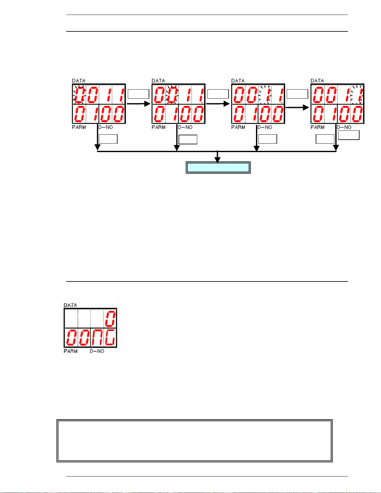
FEC Micro Nutrunner Operations Manual Chapter 7: System Operations (Rev. 2.1: 12/12)
MODE
MODE
MODE
SET
① ② ③
④
Preset display
SET
SET
SET
MODE
The larger the selection, the longer the file takes to write to the SD memory. If cycle time
is an issue, select a smaller size or data may not have enough time to be written to the
SD memory before the next cycle starts. As the SD memory fills up, writing time may
slow. Erasing the SD memory or using a new (cleared) memory will alleviate this
problem.
7.4.6 Memory Card Data File Update by Time Display / Edit mode
After entering [PESET EDIT MODE], the blinking digit will appear at the [DATA ①] field.
Use [] and [] buttons to increase or decrease data at blinking digit.
Press [MODE] button to move blinking cursor [DATA ①]→ [DATA ②]→[DATA ③]→[DATA ④]
and state change to [PRESET DISPLAY MODE].
After changes have been made, pressing the [SET] button will save the changes and exit to the
Preset display mode.
This data is effective when selecting update by “time”.
When actual time reaches preset time, the new file will be created automatically and saving is
continued to the new file.
[DATA ①][DATA②] :Hour Initial data : 00:00
[DATA③] [DATA④]: Minutes Preset range: 00:00-23:59
7.4.6.1 Memory Card – X-Y Curve Size Setup
NOTE: This setup only appears when DIP SW1-8 is set to “ON”
If DIP SW1-8 is set to “ON”, then the setup for the X-Y curve size will appear in
this position. The selection is the number of degrees (size) of each curve to be
saved to the SD Memory Card. There are 5 settings you can pick from that will
automatically show up on the display using the [] and [] buttons to cycle through
the selections; 0, 90, 180, 512, 1024, 2048 (degrees)
Resolution: 1 point for every 0.5 degree (Ex. A selection of 180 saves 360 points
Storage: The File saved is a CSV (Comma Separated Value) created in a “CURVE” Folder
After changes have been made, pressing the [SET] button will save the changes and exit to the
Preset display mode.
Page 7-27
Page 96
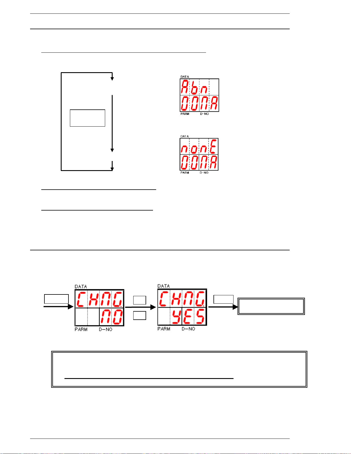
Chapter 7: System Operations
[] []
buttons
New data will not store when Power is turned OFF during edit mode.
Turn power OFF and ON after changing RS232C Mode to complete process.
All parameter data will clear when the Torque Unit is changed.
MODE
SET
RS232 preset update
7.4.7 Memory Card Abnormal Display / Edit mode
After enter [PESET EDIT MODE], current selection is blinking at [DATA] field.
Use [] and [] buttons to select desire mode.
Turn MNR controller power OFF and ON after this mode change.
Abnormal detect effective
Abnormal detect Invalid
Memory card abnormal detection effective:
The unit outputs and displays abnormal when an abnormal condition occurs.
Memory card abnormal detection Invalid:
The unit will not output and display abnormal when an abnormal condition occurs.
Fastening operation will continue and may not store result data.
7.4.8 Torque Unit / RS232C / Memory Card Data Update Confirmation
After [MODE] button is pressed, use [] and [] buttons to select YES or NO; YES means that the
data will be saved if the confirmation [SET] button is pressed. NO means that the data will not be
saved.
Note
Page 7-28
Page 97

FEC Micro Nutrunner Operations Manual Chapter 8: Maintenance and Inspection (Rev. 2: 02/12)
Chapter 8: Maintenance and Inspection
Page 8-1
Page 98

Chapter 8: System Operations
8.1 Inspection Items
A scheduled inspection is recommended to keep the Micro-NR System in the best condition. A
preventive maintenance routine should be set-up. Recommended inspection schedules are given
for each item.
WARNING:
disconnecting cabling, wiring, and equipment. Always verify the System is disabled prior
to touching any moveable components.
Follow Lockout/Tagout and other safety precautions when connecting or
8.1.1 Micro-NR (Tool)
Recommended Schedule: Quarterly
It is important to keep the nutrunners clean and properly adjusted to ensure correct fastening and
accurate system outputs. Inspect each tool and ensure the following conditions exist:
1. All environmental conditions are within the specified ranges.
2. The duty cycle is within specifications and the motor is producing normal heat levels.
3. The tool is producing normal levels of noise and vibration.
4. The tool is free from excessive contamination and foreign matter.
5. The tool is securely mounted, with mounting bolts properly tightened.
6. The homerun cables are securely connected to the tool.
8.1.2 Homerun Cable
Recommended Schedule: Quarterly
This cable connects the tool to the MNR Unit. Ensure the following conditions are met:
1. The cable is free from unnecessary force and tension.
2. The cable is secured away from any movement.
3. The cable is in good condition, sufficiently insulated with no indication of broken wires.
4. The cable is free from excessive contamination and foreign matter.
5. The cable is securely connected to the MNR Unit and to the nutrunner.
6. The cable is free from heat distortion and is not warm or hot to the touch.
7. The cable and cable connector securely and correctly fastened.
Page 8-2
Page 99

FEC Micro Nutrunner Operations Manual Chapter 8: Maintenance and Inspection (Rev. 2: 02/12)
8.1.3 MNR Unit
Recommended Schedule: Quarterly
The MNR Unit requires careful use and handling. Inspect each MNR Unit and ensure the
following requirements are met:
1. The environmental conditions are within specifications.
2. There is no moisture, oil, or foreign matter on the unit.
3. The unit is securely mounted, with appropriate clearance on all sides.
4. All screws (for the cover of the unit and for mounting) are correctly tightened.
5. The input power remains within specifications at all times.
6. The unit is not producing any abnormal (excessive) heat.
7. Unit cables (on the front and the underside) are securely fastened and without damage.
8.1.4 Air Handling Units (Air Conditioner, Heat Exchanger, etc.)
Recommended Schedule: Every 2 months (sooner if external environment is harsh; IE: machining
area with coolant mist in air).
Equipment supporting the Micro NR system environment must be sufficiently maintained. Internal
electrical enclosure (which the MNR Units are housed) heat load can be calculated using the
internal power consumption data in table 2.3. Verify support equipment meets the following
requirements, as applicable to the unit type:
1. The unit is free from dust, oil and foreign matter.
2. All filtration devices are clean and air flow is not impeded.
3. The unit is securely and correctly mounted.
4. The input power remains within specifications at all times.
5. All fans are functioning properly with no abnormal sound or vibration.
Page 8-3
Page 100

Chapter 8: System Operations
8.2 Basic Operational Tests
WARNING:
disconnecting cabling, wiring and equipment. When performing the following inspections,
verify that the system is disabled prior to touching any moveable components.
Follow Lockout/Tagout and other safety precautions when connecting or
8.2.1 Torque transducer.
The system can perform a transducer check before each fastening cycle, comparing the values
from the torque transducer (zero and calibration) to the data stored in the system memory. The
system is maintenance free. However, it can be manually checked as follows:
1. Be sure that the nutrunner is in the READY mode. (powered up and not running with a
STOP signal applied)
2. Check that the DATA display shows “ACC” when the keyboard-display RESET key is being
pressed.
3. At the same time as 2 (above), check that the SATAUS LED is green.
4. Check that the DATA display is showing “ACC” when the keyboard-display CAL key is
being pressed.
5. At the same time as 4 (above), check that the STATUS LED is green.
If any of these checks fail internal limits, an ABNORMAL will be generated and the STATUS LED
will be red. See Chapter 9 for troubleshooting.
8.2.2 Resolver.
Take the following steps to manually inspect the resolver:
1. Make sure that the system will not be started up by the PLC (use the manual mode).
2. Place the MNR keyboard-display into the Real-time Display Mode (Chapter 7 - Display has
only one digit active in the D-NO display). The [D-NO] display must be set to [0] using the
arrow keys in order to see the angle of rotation on the DATA display.
3. If the socket of the tool is turned in the clockwise direction, the angle indication should
increase.
4. Verify that the angle of rotated matches the indicated angle in the data display.
Page 8-4
 Loading...