

Page 1

CHAPTER 8: MAINTENANCE AND INSPECTION
Page 8 - 1
Page 2

CHAPTER 8: MAINTENANCE AND INSPECTION
8.1 Inspection Items - Visual and Sensory
A scheduled inspection is recommended to keep the AFC1150 system in best condition.
A preventive maintenance routine should be practiced monthly.
WARNING
VERIFY SYSTEM POWER IS OFF PRIOR TO INSPECTING. IF POWER ON IS
REQUIRED, AS IN THE ASSESSMENT OF VIBRATION AND NOISE, FOLLOW
ALL SAFETY PRECAUTIONS.
!!
8.1.1 Tool Inspection (Motor and Transmission)
Carefully inspect for the following:
P Is the environment within the specified ranges?
P Is the motor overheating because of a high duty cycle?
P Is the tool producing abnormal noise or vibration?
P Is the tool free from excessive contamination and foreign objects?
P Is the tool mounted securely, with mounting bolts properly tightened?
P Does the rotor turn freely, with no binding?
P Are the homerun cables securely connected?
8.1.2 Homerun Cables
These cables connect the axis unit to the tool. Carefully inspect for the following:
P Is the cable free from unncecessary binding, stress, or tension?
P Is the cable free from contact with moving parts?
P Is the cable free from damage and broken wires?
P Is the cable free from excessive contamination and foreign objects?
P Is the cable properly connected and securely tightened?
P Is the cable free from external heat distortion?
P Is the cable generating heat (warm or hot to the touch)?
P Are the connectors securely fastened, with connector screws properly tightened?
8.1.3 Axis Unit
Under certain conditions, environments, and usage, the components of the system may be
damaged. Carefully inspect for the following:
P Are the Abnormal LED indicators on the display indicating normal operation?
P Is the voltage within the specified range, without any sudden transient changes?
P Is the environment (temperature, humidity, vibration) within specifications ?
P Is the unit free from any dust, foreign objects, and oil?
P Is the unit properly mounted?
P Are the mounting screws and connector screws properly tightened?
P Is the input power within the specification?
P Is the unit radiating normal heat levels?
P Are the cables on the front panel properly and securely attached?
Page 8 - 2
Page 3
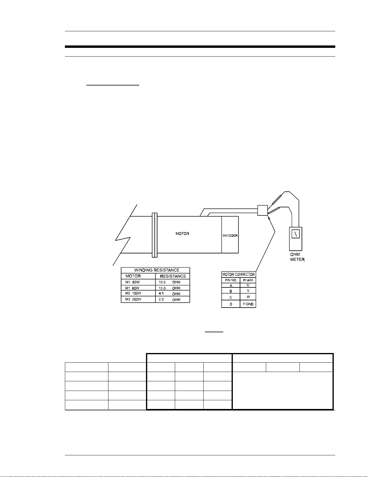
8.2 Inspection Items - Motor
WARNING!!
VERIFY POWER IS OFF BEFORE REMOVING THE TOOL ASSEMBLY FROM
THE MOTOR CONNECTOR.
w Disconnect the motor connector from the tool assembly.
w Measure the resistance between windings, as shown below.
w Measure the insulation resistance between each winding and the frame, as shown below.
NOTE: To perform this inspection, use a 500 VDC megohmmeter capable of measuring at
least 50 Mohms.
CHAPTER 8: MAINTENANCE AND INSPECTION
Fig 8.2
INSULATION RESISTANCEWINDING RESISTANCE
15.5 ohm15.5 ohm15.5 ohm60 WW1
13.0 ohm13.0 ohm13.0 ohm60 WM1
4.5 ohm4.5 ohm4.5 ohm100 WM2
2.0 ohm2.0 ohm2.0 ohm200 WM3
MORE THAN 50 Mohms
C-DB-DA-DB-CA-CA-BWATTAGEMOTOR TYPE
Page 8 - 3
Page 4

CHAPTER 8: MAINTENANCE AND INSPECTION
8.3 Transmission Disassembly and Inspection.
w The planetary gear transmissions of the AFC1150 system's tool assemblies are designed
to withstand the forces exerted upon them by the production requirements of modern
assembly plants.
w To prolong the life of the transmission assembly, an inspection and regreasing of the
components must be performed at regular intervals.
P FEC INC. encourages this procedure be performed on a yearly basis or every
500,000 cycles, whichever occurs first.
P After the initial maintenance is performed on the transmission assemblies, an
analysis can be done and a determination can be made as to the continuing
requirement for maintenance.
P Systems operating under more severe conditions may require maintenance every
500,000 cycles, while other systems may only require maintenance every
2,000,000 cycles.
8.3.1 Procedure
WARNING!!
VERIFY POWER IS OFF BEFORE REMOVING THE TRANSMISSION FROM THE
TOOL ASSEMBLY.
w REMOVE TRANSMISSION FROM TOOL ASSEMBLY
P Separate the transmission from the motor by removing four screws.
P Remove the snap ring from the output shaft.
P Separate the spacer from the transmission by removing four screws.
w DISASSEMBLE TRANSMISSION
P Reference the appropriate transmission assembly drawing during disassembly.
w CLEAN TRANSMISSION PARTS
P All parts shall be cleaned in an appropriate solvent (ex: mineral spirits) to remove
P After parts are removed from cleaning solvent they shall be placed in an
w INSPECT TRANSMISSION PARTS
P Examine all gears, pins, bearings, etc. for signs of excessive wear.
P Replace any part that is suspect of failure.
w LUBRICATE TRANSMISSION PARTS
P The transmission shall be reassembled in an area that is free of contamination.
P All bearings shall be repacked, and all gears shall be coated with grease prior to
P Pay careful attention not to pack the transmission housing with excessive grease,
P Recommended grease: Sunoco Sunaplex 992 EP or equivalent.
all excess grease and contamination.
appropriate fast drying solvent to remove any residue left behind from the cleaning
process.
reassembly.
as too much grease may be harmful.
w REASSEMBLE TRANSMISSION
P Reference the appropriate transmission assembly drawing during reassembly.
P Gears may need to be rotated to aid in the assembly process.
P If the transmission does not rotate freely after reassembly, then disassemble it
again to isolate and correct the cause.
Page 8 - 4
Page 5

w REASSEMBLE TOOL
P Connect the transmission to the motor by installing four screws.
P The output shaft may need to be rotated to align the transmission planetary gears
with the motor output splined shaft.
P Connect the spacer to the transmission by installing four screws.
P Install the snap ring on the output shaft to hold the outer bearing in place.
P If the transmission does not rotate freely after reassembling the tool, then
disassemble it again to isolate and correct the cause.
w INSPECT SPINDLE ASSEMBLY
P Prior to installing the tool, inspect the spring loaded spindle assembly that will
connect to the tool.
P The assembly should compress evenly, without binding.
P Rotate the assembly in the housing and make note of any binding.
P Visually inspect the entire assembly for signs of wear or fatigue.
P Replace parts as required and reassemble.
P Lubricate the inner bearings of the housing as required and reinspect the final
assembly.
P Install the tool onto the spindle, and again inspect for binding.
CHAPTER 8: MAINTENANCE AND INSPECTION
Page 8 - 5
Page 6

CHAPTER 8: MAINTENANCE AND INSPECTION
8.4 Replacements
WARNING!!
Verify system power is off before attempting to replace any system
components.
8.4.1 Axis Unit
An axis unit cannot be partially replaced. The entire unit must be replaced with an identical
unit, of the same model and with the same capacity (refer to Chapter 2 - Specifications). Prior
to installation, set the dip switches on the new unit in accordance with the application
requirements.
8.4.2 Tool Unit
The gear, motor, and encoder are assembled as a complete unit. If a problem arises in one
of the components, the entire tool unit should be replaced in order to ensure the highest level
of performance. Verify that the new tool is of the same type as the one being replaced.
8.4.3 Cables
An extra set of cables can be supplied with the AFC1150. The spares could be used to assist
in troubleshooting, or to replace damaged operational cables. If cable replacement is
required, carefully disconnect damaged cable, and re-connect with known good spare. Verify
for proper operation. FEC INC. recommends the use of FEC INC. cable assemblies only, and
will not warranty damage caused from other cable.
Page 8 - 6
 Loading...