

FEC AFC1500 User Manual

ELECTRIC SERVO NUTRUNNER
AFC1500 MULTI SYSTEM
MULTI-2 UNIT HARDWARE MANUAL
SECOND Edition March 2009
Automation Systems
51327 Quadrate Drive Phone: (586) 781-2100
Macomb, MI. 48042 Fax: (586) 781-0044
Web: www.fec-usa.com E-mail: sales@fec-usa.com
AFC1500E-HM2-2

WARNING
All applicable national and local codes must be followed when installing and operating the equipment detailed in
this manual.
FAILURE TO ABIDE BY THESE CODES AND THE SPECIFICATIONS DESCRIBED IN THIS MANUAL CAN
RESULT IN SERIOUS INJURY TO PERSONNEL AND/OR DAMAGE TO THE EQUIPMENT!
Any questions regarding the contents of this document or any related matter should be
directed to FEC INC. at (586) 781-2100, faxed to (586) 781-0044 or emailed to support@fec-usa.com.
The information set forth in the following document is the property of FEC INC.
This document shall not be released to or copied for any person and/or organization
without the expressed prior consent of FEC INC.
Unauthorized reproduction or distribution of this manual is strictly prohibited.
Please contact FEC INC. if you require additional copies.
ii
Revision
Revision affecting most chapters including minor fixes, revised
HS
DSP1500
FUSION
= DC Hand Tool
E
1 04/2008 Initial Release
Revision
Date
Revision History
2 3/2009
2.1 2/2010 Chapter 5 only- revised toolsnet version output format pg: 5-74 to 5-83
DSP1500 = Servo Press
AFC1500 = Nutrunner
AFC1500 = Nutrunner
FUSION = DC Hand Tool
= English Version
S = Spanish Version
*Japanese Version furnished by DDK
(uses DDK numbering convention)
= Servo Press
information and new items – Added Ethernet, Profinet & Toolsnet info.
Manual Numbering Convention
AFC1500E-HM2-2
Version Number
(Major Revision Level)
= SAN Unit Hardware
Operation Manual
HM2 = Multi2 / Main Unit
Hardware Operation Manual
HM-ENET = Ethernet Manual for
Multi / Main Unit
SW = Software Manual
iii
Introduction
Thank you for purchasing our Electric Servo Nutrunner - AFC1500 System.
This instruction manual describes the procedures for installation, wiring, handling and actions to
be taken in case of any failure.
◆
This instruction manual shall be delivered to the end user who operates the equipment.
◆
Read all instructions before use, and always keep this instruction manual with the equipment.
◆
Items not described in this instruction manual shall be considered “unavailable”.
◆
The product specification and appearance described in this instruction manual is subject to change
without notice.
◆
All rights reserved. Any disclosure, copying, distribution, or use of the information contained herein
for other than its intended purpose is strictly prohibited.
◆
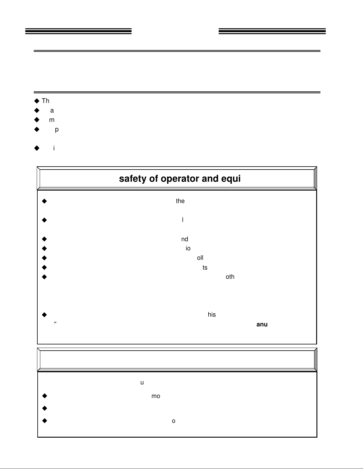
Read all “Safety Precautions” before using the equipment, and understand and observe all
instructions and recommendations included in this manual.
◆
Read all instructions and recommendations included in this manual, understand the functions
and performance of this nutrunner and correctly use this machine.
◆
Wirings and parameter settings shall only be conducted by a qualified professional.
◆
Never conduct a withstand voltage test or insulation resistance test on this equipment.
◆
Only operate this equipment with FEC supplied controllers, tools & cables.
◆
All stated warranties become invalid if other components are used.
◆
This system may be sold as components to a manufacturer (other than FEC) of a complete
system. The manufacturer of the complete system is responsible for adhering to stated
operation and safety brought forth in this manual. It is agreed between the buyer and FEC
that it is the buyer’s responsibility to adhere to this manual.
◆
Indicate the following on all instruction manuals that use this equipment.
“
This equipment must be operated in accordance to FEC Supplied Manuals”
”This equipment is capable of high voltages hazardous to human life.”
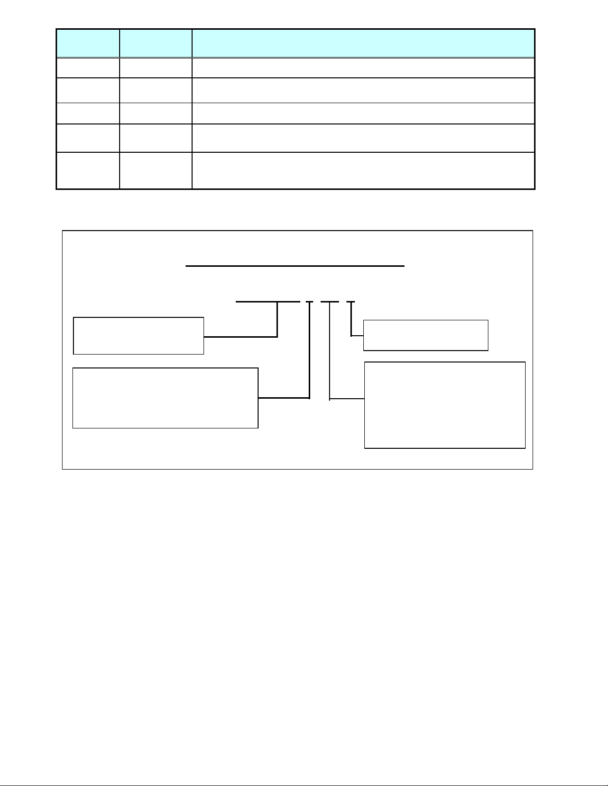
Please confirm the followings when unpacking this equipment.
◆
Ensure that you received the correct model as ordered.
◆
Ensure that there are no missing parts.
◆
Check for any damage caused during transportation.
For the safety of operator and equipment
Points to check when unpacking
iv

Introduction
Warranty Period
Provisions of Warranty
Non - Warranty Items
FEC Inc. warrants that the equipment manufactured by it and delivered hereunder will be free of defects in
material and workmanship for a period of twelve (12) months from the date of placing the equipment in operation,
or eighteen (18) months from the date of shipment, or 500,000 machine cycles - whichever shall first occur.
Should any failure to conform to this warranty be reported in writing to the company within said period, the
company shall at its option, correct such nonconformity by suitable repair to such equipment or furnish a
replacement part from FEC or an FEC approved facility, provided the purchaser has stored, installed, maintained
and operated such equipment in accordance with good industry practices and has complied with specific
requirements & recommendations of the company. Accessories or equipment furnished by the company shall not
be liable for any repairs, replacements or adjustments to the equipment or any costs of labor performed by the
purchaser or others without the company's prior written approval.
The effects of corrosion, erosion and normal wear and tear are specifically excluded from the company's
warranty. Performance warranties are limited to those specifically stated within the company's proposal. Unless
responsibility for meeting such performance warranties are limited to specified shop or field tests, the company's
obligation shall be to correct in the manner and for a period of time provided above.
THE COMPANY MAKES NO OTHER WARRANTY OR REPRESENTATION OF ANY KIND WHATSOEVER,
EXPRESSED OR IMPLIED, EXCEPT THAT OF TITLE, AND ALL IMPLIED WARRANTIES, INCLUDING ANY
WARRANTY OF MERCHANTABILITY AND FITNESS FOR A PARTICULAR PURPOSE, ARE HEREBY
DISCLAIMED.
Correction by the company of nonconformity's, whether patent or latent in the manner and for the period of time
provided above, shall constitute fulfillment of all liabilities of the company for such nonconformity's, whether based
on contract, warranty negligence, indemnity, strict liability or otherwise with respect to, or arising out of such
equipment.
The following are defined as non-warranty situations that are outside the scope of warranty provided:
•
Product is out of the warranty period as determined by FEC serial number tracking.
•
Any cause external to the equipment, including but not limited to any act of God, lighting or power surges, abuse,
negligence, accident or failure to maintain the proper operating environment.
•
Use of equipment or adjustments or devices not approved by the manufacturer and FEC.
•
Cosmetic damage to unit or any of the parts
•
Consumable parts - for example; sockets, rest/wear pads, bushings, etc.
•
Physical damage (example - damage caused by dropping, cut cables, etc.)
•
Field Service required on a Warranty Part - FEC warranty covers the parts and labor only onsite at FEC.
Extended warranties are available as an addition to the standard warranty period outlined above - for all FEC Inc.
systems. For extended warranties, contact FEC.
Warranty
v
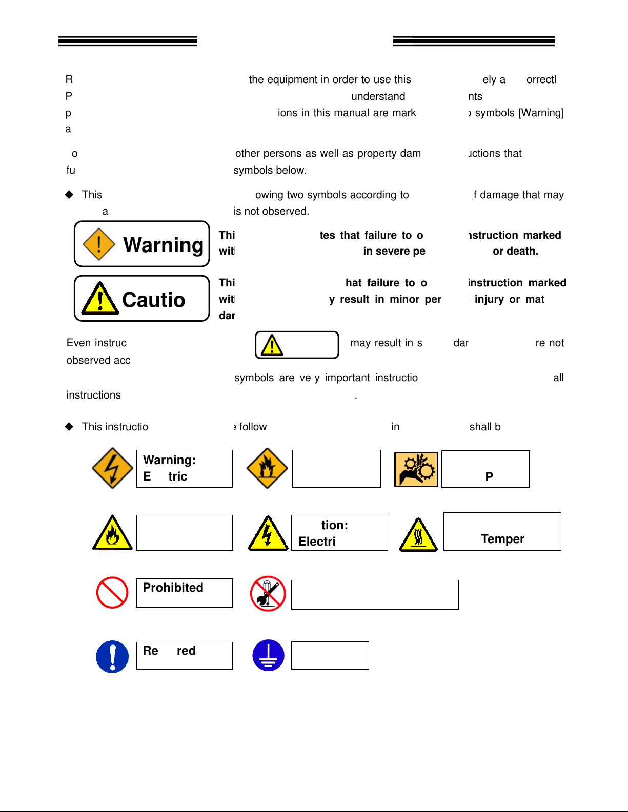
ead all instructions before operating the
manual carefully
. Safety precautions in this manual are marked with two symbols
To prevent danger to the user and other persons as well as property damage
lly observed are marked with the symbols below.
This instruction manual uses the
be caused when the instruction is not observed.
nstructions that are marked with
marked with the above symbols are very
marked with the
the following additional
This symbol indicates that failure to observe instruction
with this symbol
This symbol indicates that failure to observe instruction marked
with this symbol
damage.
Safety Precautions
equipment safely and
the equipments functions, safety
nstruction
two symbols according to the degree of damage that may
may result in severe damage if they are not
instructions. For your safety, f
s that shall be observed.
may result in severe personal injury or death.
personal injury or
Caution:
High
Warning:
Pinch Point
Caution
R
Prior to use, read this instruction
precautions and instructions
and [Caution].
fu
◆
Even i
observed according to conditions.
Warning
Caution
equipment in order to use this
and fully understand
following
may result in minor
, i
correctly.
[Warning]
s that must be
marked
material
Contents
instructions and especially those
◆
This instruction manual uses
Warning:
Electric shock
Caution:
Fire
Prohibited
Required
important
se symbols.
symbols for instruction
Warning:
Fire
Caution:
Electric shock
Do not disassemble
Ground
ollow all
Temperature
vi

Never touch rotating devices or any part of the nutrunner
Make sure that no part of your body gets near any moving part of the tool.
The spindle may rotate unexpectedly, resulting in injury.
spindle may rotate and cause injury.
Do not repair, disassemble, or modify the equipment
this instruction may cause
Never operate the equipment
Failure to observe
Keep fingers away from the
the equipment is turned OFF.
operation and maintenance work shall be conducted by a
this instruction may cause
Turn OFF the power when conducting wiri
this instruction may cause
damage the cables, apply excess
Never use damaged cables.
this instruction may cause
3 grounding of FG terminals.
this instruction may cause
abnormal odor, noise, or operation error
source.
device
this instruction may cause
emergency stop circuit
Failure to observe
Keep away from the equipment
a
this instruction may cause
Safety Precautions
tool while it is rotating.
individual components of the system.
injury, electric shock, fire and malfunction.
for a while after
electric shock
professional.
the cables.
stop operation
injury and fire.
of equipment in order to stop
and
suddenly restart.
Warning
Do not remove the motors
The tool output
and gear cases of tools while power is applied.
Failure to observe
flammable gases.
Wiring
Failure to observe
Failure to observe
Never
Failure to observe
Use type-
Failure to observe
In case of an
and turn OFF the power
Install a Power shutdown
Failure to observe
Install an
promptly.
measures are conducted
Failure to observe
where it is exposed to water, near a corrosive
this instruction may cause fire.
connectors while the equipment is turned ON and
Failure to observe this instruction may cause
electric shock and injury.
ng operation and maintenance.
electric shock and injury.
stress to cables, or squeeze
electric shock and fire.
electric shock.
Failure to observe this instruction may cause
in order to ensure the safety of equipment.
injury.
on the outside
this instruction may cause injury.
during recovery from a temporary blackout
fter restarting the equipment. The equipment may
injury.
occurrence,
qualified
atmosphere or
.
immediately
operation
ensure safety
vii
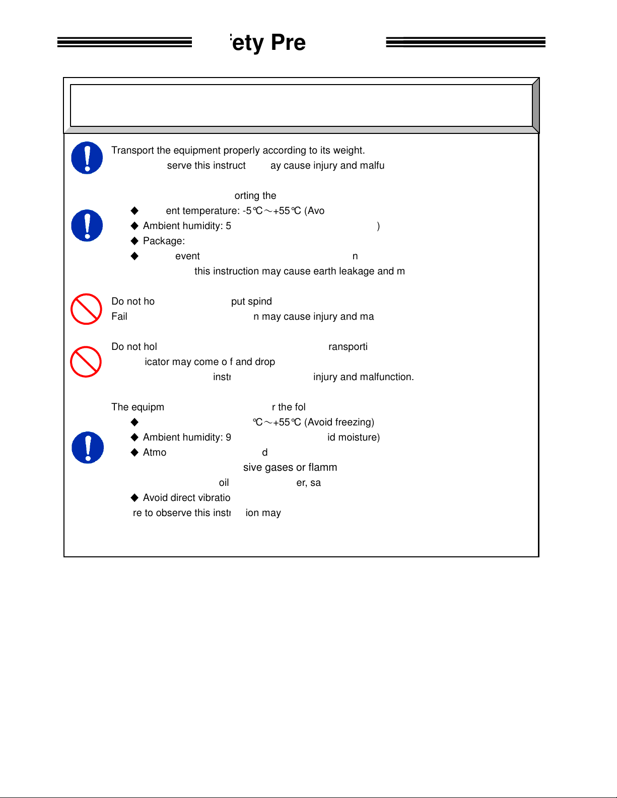
Transport the equipment properly according to its weight.
this instruction may cause
The conditions when transporting the equipment by ship is as below.
Ambient temperature:
5
Package: Tight seal
Rust prevention measure: Apply grease or oil on tools.
this instruction may cause
Do not hold cables and output spindles when transpo
this instruction may cause
indictor on the
The indicator may come off and drop from the front panel.
this instruction may cause
The equipment shall be stored under the following conditions.
Ambient temperature:
Ambient humidity: 90% RH or lower
Indoors (Avoid direct sunlig
corrosive gases or flammable gases
No oil mist, dust, water, salt, iron powder
Avoid direct vibration or shocks
this instruction may cause
Transportation / Storage
Safety Precautions
Caution
Failure to observe
injury and malfunction.
◆
◆
Ambient humidity:
◆
◆
Failure to observe
-5°C~+55°C (Avoid freezing)
0% RH or lower (Avoid moisture)
earth leakage and malfunction.
Failure to observe
Do not hold the
front panel when transporting the AXIS Unit.
injury and malfunction.
Failure to observe
injury and malfunction.
◆
◆
◆
Atmosphere:
◆
Failure to observe
No
-5°C~+55°C (Avoid freezing)
(Avoid moisture)
ht)
earth leakage and malfunction.
rting the tools.
viii

where they can bear the maximum torque
this instruction may cause
this instruction may cause
Use the specified tool for the AXIS
this instruction may cause
nit shall
this instruction may cause
ventilation hole
from entering
this instruction may cause
The power source shall be provided with safety measures
Failure to observe
(S
this instruction may cause
get on the top of equipment or do not place heavy
this instruction may cause
equipment
this instruction may cause
and firmly
this instruction may cause
Operate the equipment within the specified power supply voltage
this instruction may cause
measures to
electrical
where the equipment is subjected to
high
this instruction may cause
Safety Precautions
Installation / Wiring
during operation.
such as breakers
on the top of equipment.
and malfunction.
injury, electric shock, fire and malfunction.
hen operating the in the following
magnetic field
injury, false operation, and malfunction.
Caution
Install all tools firmly
Failure to observe
Install the AXIS Unit firmly
Failure to observe
Failure to observe
The AXIS (SAN) U
Failure to observe
Do not block the
Avoid any foreign body
Failure to observe
protectors.
Do not use tools or AXIS
Failure to observe
Do not
Failure to observe
Do not subject the
Failure to observe
Apply proper wiring size
Failure to observe
Failure to observe
Take sufficient
conditions:
◆
Location where
◆
Location
◆
Location near a
Failure to observe
injury and malfunction.
inside the control panel using the specified screws.
malfunction.
(SAN) Unit.
fire and malfunction.
maintain the specified distance from other devices.
fire and malfunction.
of the AXIS (SAN) Unit.
inside the equipment.
fire and malfunction.
this instruction may cause fire and malfunction.
AN) Units that are damaged or missing parts.
fire, injury and malfunction.
injury and malfunction.
to excess shock and impact.
malfunction.
tighten all termination points.
injury, false operation
shield the equipment w
noise is generated
power wire.
objects
a strong electric field or
.
and circuit
ix
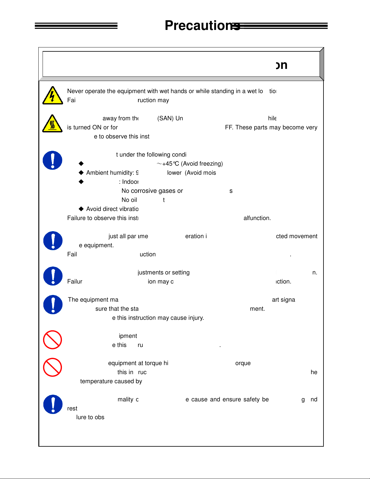
Never operate the equipment with wet hands
this instruction may cause electric shock.
Keep fingers away from the
is turned ON or for a while after the equipment is turned OFF.
this instruction may cause burns.
Use the equipment under the following conditions.
Ambient temperature: 0°C
Ambient humidity: 90% RH or lower
rs (Avoid direct sunlight)
corrosive gases or flammable gases
No oil mist, dust, water, salt, iron powder
Avoid direct vibration or shocks
this instruction may cause
ll parameters before operation
this instruction may cause injury,
adjustments or setting changes that may cau
this instruction may cause injury,
The equipment may restart suddenly
Always ensure that the start signal is OFF
instruction
Do not turn the equipment ON and OFF repeatedly.
instruction
equipment at torque higher than
Failure to observe this instruction may shorten
high temperature caused by overload.
In case any abnormality occurs,
Failure to observe this instruction may cause injury.
Safety Precautions
Operation
/ Adjustment
or while standing in a wet location
tool motors while the equipment
These parts may become very
in order to prevent unexpected movement
and malfunction.
se instability of
and malfunction.
is reset with the start signal ON.
.
or cause malfunction
remove the cause and ensure safety before resetting and
Caution
Failure to observe
AXIS (SAN) Unit radiating fin and
hot. Failure to observe
◆
◆
◆
Atmosphere: Indoo
◆
Failure to observe
Confirm and adjust a
of the equipment.
Failure to observe
No
Never conduct extreme
Failure to observe
Failure to observe this
~
+45°C (Avoid freezing)
when the equipment
may cause injury.
Failure to observe this
Do not use the
may cause malfunction.
(Avoid moisture)
earth leakage and malfunction.
false operation
false operation
before resetting the equipment.
the maximum torque capacity
equipment life
.
operation.
due to the
restarting the equipment.
x

Table of Contents
Chapter 1: Outline
1.1 About this Manual......................................................................................... 1-2
1.2 Functions...............................…..……………………………………………… 1-3
1.3 Safety Precautions……….....…..………………………………………………. 1-4
Chapter 2: Specifications
2.1 Specifications.........................………………………………………………….. 2-2
2.2 Unit Dimensions……….................................…….…………………………… 2-3
Chapter 3: System Description
3.1 System Block Diagram...........………………………………………………….. 3-2
3.2 Unit Description…….....................................…….…………………………… 3-3
Chapter 4: Installation & Wiring
4.1 Installation…….............................................…….…………………………… 4-2
4.2 Power Wiring Reference........………………………………………………….. 4-3
4.3 Input Power Connection........………………………………………………….. 4-4
4.4 RS485 Connection…….........………………………………………………….. 4-4
4.5 User Console Ethernet Connection..………………………………………….. 4-5
4.5.1 Optional Ethernet Port – Data Communication………………………….. 4-6
4.6 Serial Communication Ports..………………………………………………….. 4-7
4.6.1 PC Port………............................………………………………………….. 4-8
4.6.2 Display Port…............................………………………………………….. 4-9
4.6.3 Data-Out (1) Port........................………………………………………….. 4-9
4.6.3.1 Available Output Data...........………………………………………….. 4-10
4.6.3.2 Output Data Format..............………………………………………….. 4-11
4.6.4 Data-Out (2) Port........................………………………………………….. 4-12
4.6.5 Data-In Port…............................………………………………………….. 4-12
4.7 PLC Interface Communication (I/O).………………………………………….. 4-13
4.7.1 Control Interfaces…....……………………………………………………... 4-13
4.7.2 Input Signals………………………………………………………………….. 4-14
4.7.3 Output Signals…………………………………………………………………4-15
4.7.4 Signal Timing Chart…………………………………………………………. 4-18
4.7.5 External DIP Switch Setting……………………………………………….. 4-19
4.8 Setting Default TCP/IP Address – User Console Port……………………….. 4-19
4.9 Firmware Flash Connector……………………………………………………... 4-19
xi

Table of Contents
Chapter 5: Control Interfaces
5.1 Interface Board ……......…….………………………………………………….. 5-2
5.2 Interface Board DIP Switch Setup................…….…………………………… 5-2
5.3 Discrete I/O Interface….........………………………………………………….. 5-3
5.3.1 Sinking Type (NPN)…................………………………………………….. 5-3
5.3.1.1 Discrete Signal Connection (Sinking Type)………………………….. 5-4
5.3.2 Sourcing Type (PNP)..................………………………………………….. 5-5
5.3.2.1 Discrete Signal Connection (Sourcing Type).……………………….. 5-6
5.3.3 Input Signals (PLC-IN)................………………………………………….. 5-7
5.3.4 Output Signals (PLC-OUT).........………………………………………….. 5-8
5.3.4.1 Output Data Banks.…...........………………………………………….. 5-9
5.3.5 Standard I/O Cable – Wire Color Code……………………………………. 5-10
5.4 Interbus S® Interface..…........………………………………………………….. 5-11
5.4.1 Component Descriptions............………………………………………….. 5-13
5.4.2 User Console Software Settings ………………………………………….. 5-14
5.4.3 Input Signals (Reference Layout)..……………………………………….. 5-15
5.4.4 Output Signals (Reference Layout)……………………………………….. 5-16
5.5 DeviceNet® Interface.…........………………………………………………….. 5-17
5.5.1 Component Descriptions...........………………………………………….. 5-19
5.5.2 User Console Software Settings ………………………………………….. 5-20
5.5.3 Input Signals (Reference Layout)..……………………………………….. 5-21
5.5.4 Output Signals (Reference Layout)……………………………………….. 5-22
5.6 Profibus® Interface.……........………………………………………………….. 5-23
5.6.1 Component Descriptions............………………………………………….. 5-25
5.6.2 User Console Software Settings ………………………………………….. 5-26
5.6.3 Input Signals (Reference Layout)..……………………………………….. 5-27
5.6.4 Output Signals (Reference Layout)……………………………………….. 5-28
5.7 Modbus Plus® Interface.........………………………………………………….. 5-29
5.7.1 Component Descriptions............………………………………………….. 5-31
5.7.2 User Console Software Settings ………………………………………….. 5-33
5.7.3 Input Signals (Reference Layout)..……………………………………….. 5-34
5.7.4 Output Signals (Reference Layout)……………………………………….. 5-35
5.8 CC-Link® Interface (Version 1)..……………………………………………….. 5-36
5.8.1 Component Descriptions........... ………………………………………….. 5-38
5.8.3 Input Signals (Reference Layout)..……………………………………….. 5-40
5.8.4 Output Signals (Reference Layout)……………………………………….. 5-41
5.9 CC-Link® Interface (Version 2)..……………………………………………….. 5-42
5.9.1 Component Descriptions............………………………………………….. 5-44
5.9.2 User Console Software Settings ………………………………………….. 5-46
5.9.3 Input Signals (Reference Layout)..……………………………………….. 5-47
5.9.4 Output Signals (Reference Layout)……………………………………….. 5-48
5.10 Allen-Bradley Remote I/O Interface………………………………………….. 5-49
5.10.1 Component Descriptions...........………………………………………….. 5-51
5.10.2 User Console Software Settings .……………………………………….. 5-52
5.10.3 Input Signals (Reference Layout).……………………………………….. 5-53
5.10.4 Output Signals (Reference Layout).…………………………………….. 5-54
xii

Table of Contents
5.11 Ethernet-I/P Interface…........………………………………………………….. 5-55
5.11.1 Component Descriptions...........………………………………………….. 5-56
5.11.2 User Console Software Settings. .……………………………………….. 5-57
5.11.3 Input Signals (Reference Layout).……………………………………….. 5-58
5.11.4 Output Signals (Reference Layout)..…………………………………….. 5-59
5.11.5 PLC Message Transfer Setup Example…..……………………………… 5-61
5.12 Profinet Interface……………………………………………………………….. 5-69
5.12.1 Component Descriptions………………………………………………….. 5-70
5.12.2 User Console Software Settings…………………………………………. 5-71
5.12.3 Input Signals (Reference Layout).……………………………………….. 5-72
5.12.4 Output Signals (Reference Layout)..…………………………………….. 5-73
5.13 Input / Output Signal Layout using Toolsnet Version………………………… 5-74
Chapter 6: Troubleshooting
6.1 Abnormals…………………….………………………………………………….. 6-2
xiii

Blank Page
xiv

Chapter 1: Outline

connection references
Chapter 1: Outline
AFC1500 Multi-2 Unit Hardware Manual (Rev. 2)
1.1 About this Multi-2 Unit Manual
This manual details the configuration, specifications and the operation of the AFC1500 Multi-2 Unit.
The following table outlines the contents of each chapter.
Chapter
1 Outline
2 Specifications General specifications of the AFC1500 Multi-2 Unit.
3 System Description Description of standard and optional system components.
4 Installation and Wiring
5 Control Interfaces
6 Troubleshooting Description of Abnormal conditions.
Any questions regarding the contents of this document or any related matter should be
directed to FEC Inc. at (586) 781-2100 or faxed to (586) 781-0044.
The Information set forth in the following document is the property of FEC Inc. This
document shall not be released to or copied for any person and/or organization without
the expressed prior consent of FEC Inc.
Unauthorized reproduction or distribution of this manual is strictly prohibited. Please
contact FEC Inc. if additional copies are required.
Related Documentation
Title Contents
Basic characteristics and requirements of the AFC1500
Multi-2 Unit.
Mounting requirements, wiring
including communication port specifications.
Description of standard Discrete I/O and optional Fieldbus I/O
PLC Interfaces.
AFC User Console Manual AFC1500E-SW-*
AFC1500 Operation Manual AFC1500E-HS-*
PAGE 1 - 2

AFC1500 Multi-2 Unit Hardware Manual (Rev. 2)
Chapter 1: Outline
1.2 Functions
The Multi-2 Unit is a complimentary controller device to enhance the AFC1500 SAN Unit capabilities
by providing the communication and the sequence control features required by larger or more
sophisticated multi spindle applications. When a group of AFC1500 Servo Controllers (SAN Units) are
linked to a Multi-2 Unit, the Multi-2 Unit assumes control (over these spindles) of the following
functions:
Input / Output (I/O) connection (including Fieldbus interfaces)
Sequence Control
Parameter Programming
Fastening Data Monitoring & Communication
General Status Indication
♦
Input / Output (I/O) Connection
The Multi-2 Unit assumes control of the control signals (Ex.: STOP, START, REVERSE,
BYPASS, etc.) to all of the AFC1500 Servo (SAN) Controllers connected to it via the RS485
communication port, thus eliminating direct connection & control to the individual spindles
saving costly I/O connection. The control signals for the multi-spindle array can be of
different sources: Signals manually generated by pressing the Control Buttons on the front of
the Multi-2 Unit or I/O (Input/Output) signals from a PLC and / or PC Based Controller.
Additionally, a multitude of (direct connect) Fieldbus interfaces are available when using a
Multi2 Unit.
♦
♦
Sequence Control
♦♦
The Multi-2 Unit controls the fastening sequencing eliminating the need for external control
devices (PLC) to perform complicated spindle control sequencing. All fastening sequencing is
handled by the Multi-2 Unit. This built in feature allows the Multi-2 Unit to control a variety of
complex sequencing strategies including; incremental fastening steps, spindle grouping,
reject (reverse) strategies, wait timing, multiple starts, etc. Also available are sequence
Input / Output interfaces which allow external control of sequence starting / stopping with
outside automation while in sequence.
♦
♦
Parameter Programming
♦♦
A Windows® compatible computer running the AFC User Console software package can be
connected to the Multi-2 Unit in order to upload or download the preset data to all the SAN
(Servo) Controllers connected in the multi spindle array. This eliminates the need to program
individual spindles manually.
♦
♦
Fastening Data Monitoring & Communication
♦♦
The Multi-2 Unit can monitor and process the fastening results collected by the AFC1500 Servo
(SAN) Controllers connected to it. It has four (4) configurable RS232C ports to input and output
fastening data results. Data monitoring / saving is also a function of the AFC User Console
software package.
As an added feature, the Multi-2 Unit stores previous fastening data in RAM (non-volatile) for
uploading at another time. The number of cycles stored is based on the number of spindles
connected (see chart on page 2-2). The data can be uploaded using the AFC User Console
software package.
Additionally, the Multi -2 comes standard with an dedicated ethernet port to connect to a
computer running the AFC User Console Software package making it easier to connect to most
computers without serial convertors. As an option, the Multi - 2E comes with an additional
ethernet port for reporting of resultant fastening data to host systems.
♦
♦
General Status Indication
♦♦
A set of indicator LED’s provide the status for Power On, Busy, Total Accept, Total Reject and
Abnormal conditions.
PAGE 1 - 3

Chapter 1: Outline
AFC1500 Multi-2 Unit Hardware Manual (Rev. 2)
1.3 Safety Precautions
To ensure the most effective and extended use of all equipment, adhere to the following precautions:
Wiring
• Use only the specified cables for all system connections.
• Do not use a high voltage circuit as a frame ground (FG). Also, the frame ground should be
separate from the power ground. The use of a grounding rod located as close as possible to
the enclosure housing the AFC1500 Multi-2 Unit is preferable.
• Circuit breakers or fuses are required on branch circuit power feeds to the Multi-2 Unit.
• PLC I/O cables must be run separate from any high voltage sources or cabling, and must not
exceed 50 feet.
Installation Environment
• The AFC1500 Multi-2 Unit should be placed in a NEMA 12 enclosure.
• Using the equipment in the following locations may lead to malfunction or breakdown. Avoid
using in these areas or use an air conditioner.
Areas under direct sunlight or if the environmental temperature is out of the 32~122
0~50) range.
Areas where relative humidity is out of the 20-90% range, the temperature change is
drastic or where the area is exposed to mist and water drops.
• Do not use at the following locations. (Contact FEC Inc. if necessary for clarification)
Areas where conductive powder, oil, mist, salt or organic solvents exist.
Areas that have corrosive or combustible gases.
Areas that have strong electric or magnetic fields.
Areas where strong vibration or shock could be transmitted directly to a Multi 2 Unit.
Static Electricity
• The AFC1500 Multi-2 Unit incorporates many electronic Surface Mounted Devices (SMD). It
is advisable to strictly adhere to practices for safe electrostatic discharge in order to prevent
damage to the system components when handling them.
Cleaning
• Do not use any organic solvents, such as thinner, to clean a Multi-2 Unit. The solvent could
melt the surface paint, or penetrate inside and cause damage. A cloth dampened with alcohol
or warm water should be used to lightly wipe the components.
Electrical Noise Prevention
• Multi-2 Units must be located a minimum of 600mm from high transient voltage sources such
as transformers, motor starters, AC inverters and AC contactors. If it cannot be avoided, the
unit must be shielded.
• If high powered devices are used inside the enclosure, they must use a surge suppression
device.
• Make sure that the power supply lines and cables for connecting the unit and tool are not run
together inside the same duct.
Handling and Shipping
• It is critical that AFC1500 System components are properly handled and shipped in order to
maintain the system’s integrity. Adhere to the following requirements for shipping and
handling:
Loose AFC1500 Multi-2 Units must be individually packaged and shipped in anti-static
containers or wrap to prevent damage from electrostatic discharge.
If the Multi Unit is to be shipped in an enclosure, tighten all mounting screws to prevent
the unit from being dislodged.
Do not ship or store the unit in environments where the temperature is out of the
23~131 (-5~55) range or where the humidity is above 90%.
PAGE 1 - 4

Chapter 2: Specifications

®
Additional Interfaces a
lso available:
Chapter 2: Specifications
AFC1500 Multi-2 Unit Hardware Manual (Rev.2)
2.1 Specifications
Power Supply Voltage 100 to 220 VAC±15%, 1-phase, 50/60 Hz.
Power Consumption 9 Watt/Hour
In rush current Less than 160 mA
CPU NEC V53A
Data Communication RS232C (User Console PC) (N/A with Ethernet Data Option)
RS232C (Data Output #1 / Data Output)
RS232C (Data Input)
RS232C (Data Output #2) (N/A with Ethernet Data Option)
RS422 (External Remote Display)
RS485 Servo Units Programming/Control
Ethernet - User Console (User Console PC)
Ethernet - Network Communication (OPTIONAL 2E Version Only)
Control Interfaces Discrete I/O (24Vdc Sink)
Discrete I/O (24Vdc Source)
DeviceNet
Profibus®
(Includes data messaging capability)
Profinet IO
Ethernet I/P
Mitsubishi CC Link® 1
(Includes data messaging capability)
Allen Bradley Remote I/O 1
Modbus Plus®
CC Link® Version 2
Interbus-S®
(Includes data messaging capability)
M-Net
Contact FEC for special fieldbus requirements
Fastening Sequence
Programming Steps
Fastening
Control Methods
100
(99 plus “End” Step)
Torque Control / Angle Control
Optional Yield Control (Requires SAN Ver. 2.39)
Max. No. of spindles 31 per Multi-2 Unit
Fastening Parameters 16
Fastening Sequences 16
Torque Rate
monitoring areas
Data Storage
(Non-volatile RAM)
Based on the number of
spindles connected.2
3
st
(1
, 2nd and 3rd Rate areas)
Stored
# of
Spdls.
Cycles
# of
Spdls.
1 7878
2 6032
3 4888
4 4108
5 3536
6 3120
7 2782
8 2496
Stored
Cycles
9 2288
10 2080
11 1924
12 1794
13 1690
14 1586
15 1482
16 1404
# of
Spdls.
Stored
Cycles
# of
Spdls.
17 1326
18 1248
19 1196
20 1144
21 1092
22 1040
23 1014
24 962
Stored
Cycles
25 936
26 910
27 858
28 832
29 806
30 780
31 754
Installation requirement NEMA12 Enclosure
Operation Temperature 0º to 50 ºC (32 º to 122 ºF)
Operation Humidity 20% to 90%
1) Mitsubishi CC Link & Allen Bradley Remote I/O are proprietary and licensed for use.
2) The number of cycles stored will be reduced if RS232C - DATA IN data is stored with the
fastening data.
PAGE 2 - 2
AFC1500 Multi-2 Unit Hardware Manual (Rev.2)
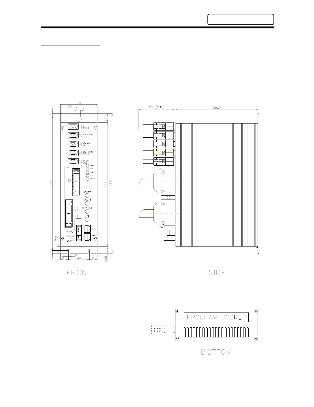
2.2 Unit Dimensions
Mounting: Top (1) place #8-32 screw
Bottom (2) places #8-32 screw
Weight: 1.4 kg
Chapter 2: Specifications
Note: Unit Dimensions are the same whether a Multi 2 unit (as shown), or a Multi 2E (Ethernet) version.

Chapter 2: Specifications
AFC1500 Multi-2 Unit Hardware Manual (Rev.2)
Blank Page
PAGE 2 - 4

Chapter 3: System Description
Chapter 3: System Description
AFC1500 Multi-2 Unit Hardware Manual (Rev.2)
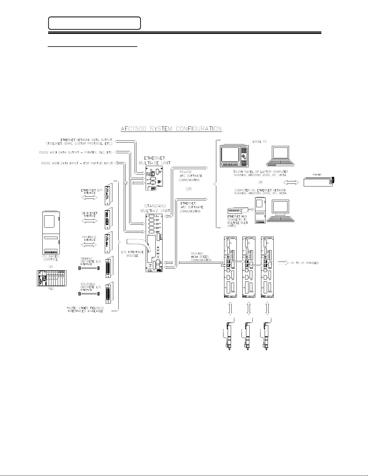
3.1 System Block Diagram
The diagram below shows how the AFC1500 Multi-2 Unit can be connected to a single unit or combined
in a multiple spindle configuration. The use of a Multi-2 Unit provides one set of PLC I/O for controlling
multiple spindle fastening operations. Along with discrete 24VDC (sinking or sourcing) I/O, various
fieldbus interfaces are also available for direct connection to networks such as Profibus, AB remote I/O,
CCLink, DeviceNet, etc.
The AFC1500 Multi-2 Unit also provides an interface for connection to the User Console PC, serial
printers, barcode readers, display units, etc.
PAGE 3 - 2
AFC1500 Multi-2 Unit Hardware Manual (Rev.2)
Chapter 3: System Description
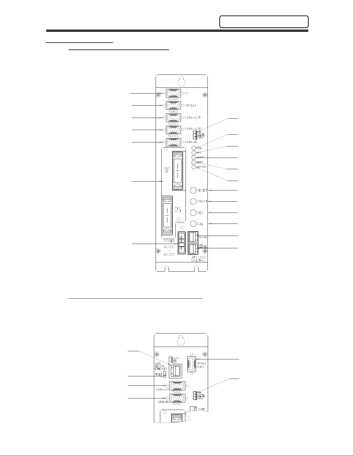
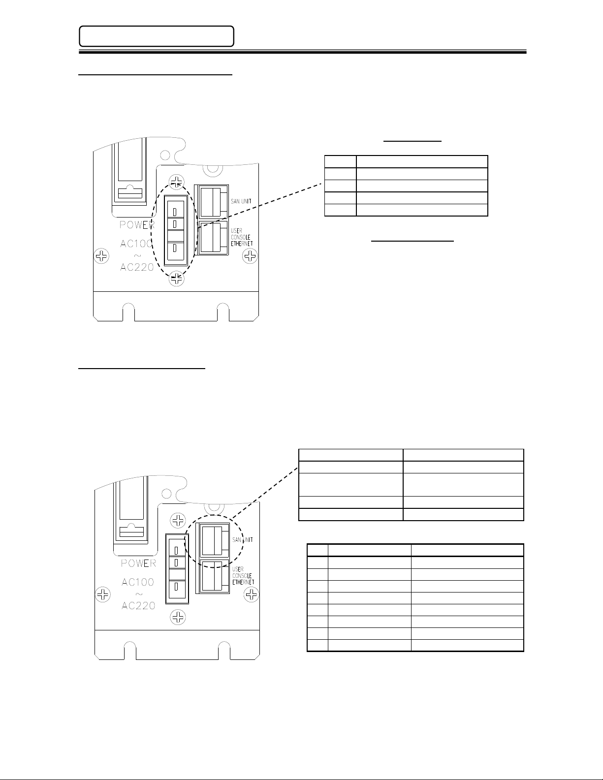
3.2 Unit Description
AFC MULTI – 2 Standard Version
The standard version of the Multi-2 unit includes both an RS232 port (PC Port) and Ethernet
port (Ethernet U/C Port) for communicating to a computer running the AFC User Console
Software. (Only one may be used at a time)
(RS232C) PC Port
(RS422) Display Port
(RS232C) Data-Out Port #1
(RS232C) Data-Out Port #2
(RS232C) Data-In Port
Ethernet U/C
Status LED
Power ON LED
Busy LED
Accept LED
Reject LED
Interface Board
Abnormal LED
Reset Button
Start Button
Reverse Button
Power Connector
Calibration Button
RS485 Port
Ethernet U/C Port
* Discrete I/O Interface Board Shown. (RS232C)Data-Out 2 and (RS422) Data-In are not used.
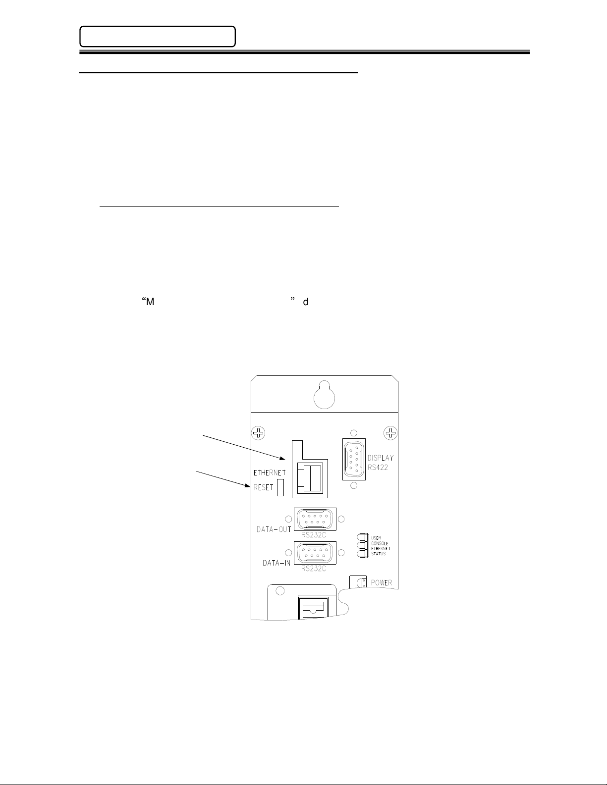
AFC MULTI – 2E Ethernet Version (Optional)
The optional ethernet version of the Multi – 2 unit adds the functionality of an additional ethernet
port for FASTENING DATA COMMUNICATION protocols to external systems as well as User
Console connectivity. Existing protocols include; QDAS, ToolsNet®, FECNet as well as custom
Protocols. The RS232 PC Port and Data-Out 2 port are removed using this configuration.
Ethernet Network Port
Ethernet Reset Button
(RS232C) Data-Out Port
(RS232C) Data-In Port
(RS422) Display Port
Ethernet U/C
Status LED
PAGE 3 - 3

Chapter 3: System Description
Multi
-
2 Unit
Panel Description
RS232C
– Data Out Port #2
Not Used
etc.)
Power On LED Indicates when power is applied to the Multi-2 Unit.
Busy LED Lights when the unit is performing a self check, return, fastening
operation or is downloading/uploading data to the AFC User Console
software package.
Accept LED Lights if a fastening cycle or a self check test falls within acceptable
parameters. (This LED indicates status for ALL connected spindles)
Reject LED Lights if a fastening cycle or a self check test is outside of acceptable
parameters. (This LED indicates status for ALL connected spindles)
Abnormal LED Lights when a system abnormal condition is detected in the control
system of any connected spindle. (Does NOT indicate a spindle reject).
All operations are halted and cannot be restarted until the Abnormal
condition is corrected. Can be cleared only by the Reset function. (see
AFC1500 Operation Manual for Abnormal Troubleshooting)
RS485 Port RJ45 style connector used to connect to all AFC1500 Servo (SAN)
Units included in the system.
Ethernet U/C Port Communication port for the AFC Software User Console PC.
Red (TX) Transmitting Data
Ethernet U/C Status LEDs
Reset Button Resets all signal and communication buffers to “clear” conditions.
Start Button Starts the fastening cycle. Requires a pulse of 0.1 to 0.5 sec. for
Reverse Button Turns the spindles in the opposite direction of the preset fastening
Cal Button Performs the Torque Transducer shunt calibration test. When pressed,
Power Connector Connects to incoming power: 100 to 220VAC (auto-sensing), Single
Interface Board (I/O) Allocation socket for input/output signal Interface boards. Options
RS232C – PC Port Communication port for the User Console PC.
RS232C – Data Out Port #1
(RS232C – Data Out Port)
RS232C – Data In Port Communication port for ASCII data input from peripheral devices. (Ex:
Yellow 10/100 Link
Green (RX) Receiving Data
Clears the Abnormal signal and performs the Torque Transducer Zero
Level Check.
“Normal” start selection or must be maintained during complete cycle
for “Deadman” start selection.
direction while the button is held active.
the Servo (SAN) Units will display either a green accept LED or red
reject LED indicating status of the individual Calibration test.
phase, 50/60 Hz.
available are Discrete I/O (Sink or Source), Interbus-S®, DeviceNet®,
Profibus®, CC-Link® (Version 1 or 2), Modbus Plus®, Allen Bradley
Remote I/O (Rockwell License #199906006) or Ethernet-I/P
Communication port for fastening result data output to any external
device, i.e.: host computer, serial printer, etc. Data output format is
configured using the User Console (AFC) Software package.
bar code readers, RF tag, etc.) Allows external ASCII data to be merged
with fastening result data.
AFC1500 Multi-2 Unit Hardware Manual (Rev.2)
RS422 – Display Port Not Used
Ethernet Network Port*
Ethernet Reset Button* For resetting the Network Ethernet Port IP address to default setting.
*On Ethernet Version only.
for network connectivity (Toolsnet®, QDAS®, SQL, Custom Protocol,
(IP: 192.168.10.40 Subnet Mask: 255.255.255.0 Gateway:
192.168.10.1)
To reset port to default IP address, power down Multi Unit. Depress
reset button and hold it depressed while powering on the Multi Unit until
green Accept LED illuminates.
PAGE 3 - 4

Chapter 4: Installation & Wiring
Chapter 4: Installation & Wiring
RS485 port specifications
(RJ45)
Protocol
Proprietary
2
1
8
AFC1500 Multi-2 Unit Hardware Manual (Rev. 2)
4.3 Input Power Connection
An auto sensing power supply allows for input power in the range of 100 ~ 220VAC single phase,
50/60 hertz. Adequate circuit protection must be provided. Recommended conductor size should be
a minimum of #18AWG.
Wiring Chart
4
3
2
1
Pin Description
4
3 100 ~ 220VAC +/-15%
100 ~ 220VAC +/-15%
No Connection **
Frame Ground
Mating Connector
Manufacture: Amp
Housing Part No.: 1-178128-4
Contact Part No.: 1-175218-3 (Qty.-3)
** To standardize components, FEC cable part
#FEB-1260 may be used due to the fact that
pin #2 is not connected internally.
4.4 RS485 Connection
The Multi-2 Unit uses an RS485 port to perform the communication operations with the AFC1500
Servo (SAN) Controllers. This port has two channels CH1 and CH2. CH1 is dedicated to handle all
preset data upload and download, fastening results monitoring and collection. Channel CH2 is a high
speed connection to all AFC1500 Servo Controllers. It controls all required commands to perform the
fastening cycle.
Speed 9600, 19200, 38400 baud
Cable Std Cat 5 Ethernet
Maximum number of
connected devices
31
Operating Voltage RS485 Standard
RS485 Wiring
NO Signal Name Channel
1 TX+ / RX+ CH1
2 TX- / RX- CH1
3 RX+ CH2
4 TX- CH2
5 TX+ CH2
6 RX- CH2
7 GND
8 GND
PAGE 4 - 4
AFC1500 Multi-2 Unit Hardware Manual (Rev. 2)
Ethernet
port specifications (RJ45)
8
Chapter 4: Installation & Wiring
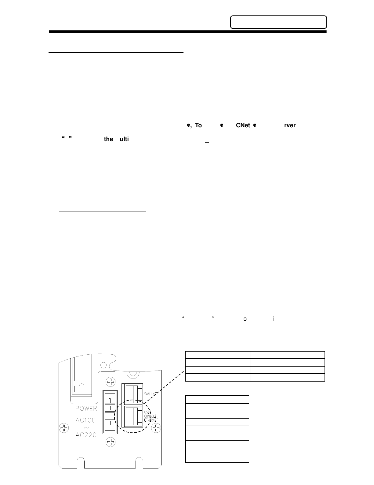
4.5 User Console Ethernet Connection
The “User Console Ethernet” port is a dedicated TCP/IP ethernet port for communicating with the
AFC User Console Software in a Windows® based PC. Similar to the serial RS232 (PC) port
dedicated for the AFC Software connection, this port allows connection in an ethernet environment vs.
using the standard serial port connection in previous versions of the Multi Unit. This port allows the
user to set-up, monitor, save data, display and print fastening data and setup parameters using the
AFC User Console software. The ethernet connection allows connection to multiple Multi-2 units
using an ethernet switch or hub. (Different IP addresses must be configured for multiple connection).
NOTE: An additional ethernet port is available for communicating fastening resultant data to
external data collection systems (ie. QDas
custom protocols). This is an OPTIONAL ethernet port and can be ordered by adding the
E
option to the Multi-2 Unit. (Part #1500Multi2E-x)
The default IP address is set at FEC or it can be configured by the user using the AFC User Console
software. If connection cannot be established using the default IP address, the IP address may
have been changed. The default IP address can be re-established by resetting it. See section
4.8.1 for resetting the IP address back to the default setting. The Multi-2 IP address may also be
uploaded, viewed and modified using the AFC software PC connected serially. (RS232 PC Port or
RS485 SAN UNIT connection) Once the current IP address configuration is verified using a serial
connection, then connection may be attempted using the Ethernet port.
Default IP Address of Multi 2 unit
IP Address: 192.168.10.10
Subnet Mask: 255.255.255.0
Default Gateway: 192.168.10.1
Note: Set-up the TCP/IP properties in the computer that will connect to the Multi-2 unit prior to
attempting ethernet port connection. The actual IP address setup in the computer must be a different
number than the Multi-2 unit IP address. Example: Using the default IP address above, set the PC
IP address to 192.168.10.50. Use the same Subnet & Gateway settings)
Note: Only one AFC Software connection method may be used at any given time whether
serial connection or Ethernet connection. The AFC Software can only be configured for one
connection port at a time. If more than one connection is required at the same time (to
additional Multi Units), additional AFC software may be installed and run at the same time,
each set-up with different communication connections.
The connecting cable is a standard Ethernet Crossover cable if connected directly to a PC (FEC
Part #FEB-1331-6). If connected through an Ethernet switch, a standard ethernet CAT5 or CAT5e
may be used (FEC Part Number FEB-1258-6).
, ToolsNet
, FECNet
, SQL Servers or other
Speed 10/100Mbps (auto select)
Cable Std Cat 5 Ethernet
Protocol Proprietary
Operating Voltage Ethernet Standard
Ethernet Wiring
Pin Signal Name
1 Tx+
2 Tx 3 Rx+
4 5 6 Rx 7 8 -
PAGE 4 - 5
Chapter 4: Installation & Wiring
AFC1500 Multi-2 Unit Hardware Manual (Rev. 2)
4.5.1 Optional Ethernet Port – Data Communication
As an option, an additional ethernet port is available for sending fastening resultant data over an
ethernet TCP/IP connection. This port can be configured using a standard web browser for
communication to Atlas Copco Toolsnet networks, FEC NET or custom protocols. Additionally,
once configured, the AFC User console software can also communicate over this port.
NOTE: Only one ethernet port may be used to communicate to the AFC software. Either the
dedicated User Console Ethernet port (located in the lower right corner of the front face) or the
optional Ethernet port.
Default IP Address of the Multi 2 Optional Ethernet Port
IP Address: 192.168.10.40
Subnet Mask: 255.255.255.0
Default Gateway: 192.168.10.1
If communication cannot be established using these settings, the settings may have been changed
in the Ethernet Port. To reset the setting back to these default settings, press the RESET
pushbutton located beside the ethernet port while powering on the unit.
See the MULTI 2E SETUP PROCEDURE document for more information when using this port.
(Contact FEC)
Optional Ethernet Port
Default Reset Button
PAGE 4 - 6
 Loading...