


QUBE PA
shapingthesoundoftomorrow
PA140
CH.2
SIG
PROT
CLIP
PWR PWRSIG SIG
G G
R R
PROT PROTCLIP CLIP
PWR
SIG
PROT
CLIP
0 100 10
CH2
100 10
POWER
POWER
Worldwidedistributor FBT
www.qubeaudio.com
FBT elettronica S.p.A. --62019RECANATI(MC)-ITALYZonaInd.leSQUARTABUE
TEL.071/750591r.a.-FAX071/7505920-P.O.BOX104-Internet:http://www.fbt.it-E-mail:info@fbt.it
POWERAMPLIFIER
CH1 CH2
PWR PWRSIG SIG
G G
R R
PROT PROTCLIP CLIP
Operatingmanual
0 100 10
POWER
FBTElettronicaS.p.A.
www.fbt.it

CAUTIONS
RISKOFELECTRICSHOCK
DONOTOPEN
TOREDUCETHERISKOFELECTRICSHOCKDONOTREMOVE
COVER.NOUSERSERVICEABLEPARTSINSIDE
REFERSERVICINGTOQUALIFIEDSERVICEPERSONNEL
TOAVOIDELECTRICSHOCKDONOT
INSERTFINGERSOROBJECTSINTO
ANYOPENINGSINTHECABINET
TOPREVENTFIREORELECTRICSHOCKDONOTEXPOSE
THISEQUIPMENTTORAINORMOISTURE
RISKOFELECTRICSHOCK:
OPENONLYIFQUALIFIEDAS
SERVICEPERSONNEL
!
TOREITERATETHEABOVEWARNINGS:SEVICINGINSTRUCTIONS
AREFORUSEBYQUALIFIEDPERSONNELONLY.TOAVOID
ELECTRICSHOCKDONOTPERFORMANYSERVICINGOTHER
THANTHATCONTAINEDINTHEOPERATIONINSTRUCTIONS
UNLESSYOUAREQUALIFIEDTODOSO.REFERALL
SERVICINGTOQUALIFIEDPERSONNEL
INTRODUCTION
Congratulationsonyourpurchaseofadualchannelprofessionalpoweramplifiers.YourQUBE
amplifierhasbeendesignedtoprovideyearsoftrouble-free,highperformanceoperation.Wehopeyouenjoyit.
Youramplifiermayincludetheplug-inloudspeakercontrollermodulesinplaceofthestandarddualchannelinputmodule.
The“controllermodulesarededicatedcompanionstoaspecificQUBEloudspeakers.Theyprovideprotectioncircuitry,
SP”
SP
electroniccrossovercircuitryandresponseoptimizationfortheirassociatedloudspeakers.
Caution:ifyouramplifierincludesa“SP”,itisconfiguredforusewithaparticularloudspeakermodelandshouldnot
beusedwithanyothermodel.Useofthewrongloudspeakermayresultinloudspeakerdamage.
YourQUBEamplifierwascompletelytestedandinspectedbeforeleavingourfactoryandshouldhavearrivedinperfect
condition.Pleasecarefullyinspectyouramplifieranditsshippingcartonforanynoticeabledamage,andifanydamageis
found,immediatelynotufytheshippingcompany,
Onlytheconsigneemayinstituteaclaimwiththecarrierforanydamageincurredduringshipping.Besuretosavethecarton
andallpackingmaterialsforthecarrier’sinspection.
Itisalsoagoodideatosavethecartonandpackingmaterialeventhoughtheamplifierarrivedingoodcondition.Ifshipping
theamplifiershouldeverberequired,itshouldbeshippedonlyinitsoriginalfactorypacking.
Important:
YourQUBEamplifiercontainsnouser-serviceablepartsandallserviceshouldbereferredtoqualifiedservicepersonnel.We
recommendthatitbereturnedtothefactoryinitsoriginalpackingcartoniffactoryserviceisrequired.
QUBEPA140/PA300/PA360
POWERAMPLIFIERS
ThePA140provides500Wofpowerperchannelusinga4
ohmspeakersystem(350Wperchannelwith8ohm)andis
theidealamplifierforQUBEQ112,Q115,QS112and
QS115speakers.ThePA140canalsobeconnectedtoa
controllermodule.
PA300isa1500Wperchannelpoweramplifierdesigned
forallthoseapplicationswherereliabilityandsoundquality
areextremelyimportant.Itincludesself-resetting
protectivecircuitrytopreventanydamage,withLEDs
indicatingthestatusofeachchannel.Othercharacteristics
includeagroundliftandselectorofbridgemode.PA300is
idealtobeusedcombinedwithQ115,QS115,QS118,BRH
andTRSQUBEspeakersystems.Theversatilityofthe
poweramplifierallowstheuseofcontrollermoduleto
processthesignal,optimisingtheoverallperformanceof
thespeakersandprotectingthematthesametimefrom
possibledamages.
ThePA360isa1800Wperchannelpoweramplifier
designedforallthoseapplicationswherereliabilityand
soundqualityareforprimaryimportance.Itincludesselfresettingprotectivecircuitrytosafe-guardagainstdamage,
withLEDsindicatingthestatusofeachchannel.Other
characteristicsincludeagroundliftswitchandselectorfor
simplesettingofstereobridgemode.ThePA360isidealfor
theusewithQUBEQSA210LINEARRAYspeaker,QS218
,BRKandRUT.Theversatilityofthesystemallowstheuse
ofacontrollermoduletoprocessthesignal,optimisingthe
overallperformanceofthespeakersandprotectingthemat
thesamefrompossibledamages.
ANALOGCONTROLLERS
Seepage8. Seepage8.
DIGITALCONTROLLERS
Seepage8. Seepage10.

TECHNICALSPECIFICATIONS
Continuouspowerbothchannelsdriven
WRMS(@THD<0.05%1kHz)
ContinuouspowerBridgemode
WRMS
Impulsivepowerbothchannelsdriven
WRMS
ImpulsivepowerBridgemode
WRMS
Inputsensitivity
Inputimpedance
Slewrate
Signaltonoiseratio
Harmonicdistortion
(1kHz-4ohm)
350W@8ohm
500W@4ohm
550W@8ohm
900W@4ohm
1300W@2ohm
850W@8ohm
1200W@4ohm
1700W@2ohm
1000W@8ohm 2600W@4ohm 3400W@4ohm
470W@8ohm
700W@4ohm
600W@8ohm
1000W@4ohm
1500W@2ohm
1400W@8ohm 3000W@4ohm
900W@8ohm
1250W@4ohm
1800W@2ohm
2500W@8ohm
3600W@4ohm
1,4Veff 1,4Veff 1,4Veff
15kOhmmin. 15kOhmmin. 15kOhmmin.
>40V/s >30V/s >30V/s
107dBw/A 110dBw/A 110dBw/A
<0,015 <0,01 <0,01
IMD
TIM
Frequencyresponse
Dampingfactor
Maxoutputvoltage
Maxcurrentoutput
Powerconsumption
Powersupply
Protections
Cooling
Dimensions
Weight
Allpowermeasurementsmadeat230V
AllmeasurementsmadeusingAUDIOPRECISIONequipment
ImpulsivepowermeasuredinaccordancewithIHFmethodwith20mSburstsandREPETITIONRATE100mS
@8ohm,1kHz
(WxHxD)inch
lb.
<0,04% <0,04% <0,015%
<-80dB <-80dB <-80dB
20Hz-20kHz 20Hz-20kHz 20Hz-20kHz
>400 >400 >200
90Vp 100Vp 85Vp
25Aeff 63Aeff 84Aeff
1500VA 2800VA 3500VA
230Vac 230Vac 230Vac
DC/Thermal/SOA DC/Thermal/SOA DC/Thermal/SOA
variablespeedfan 2variablespeedfan 2variablespeedfan
19x3.5x19 19x5x19 19x5x19
40.5 66 81.5
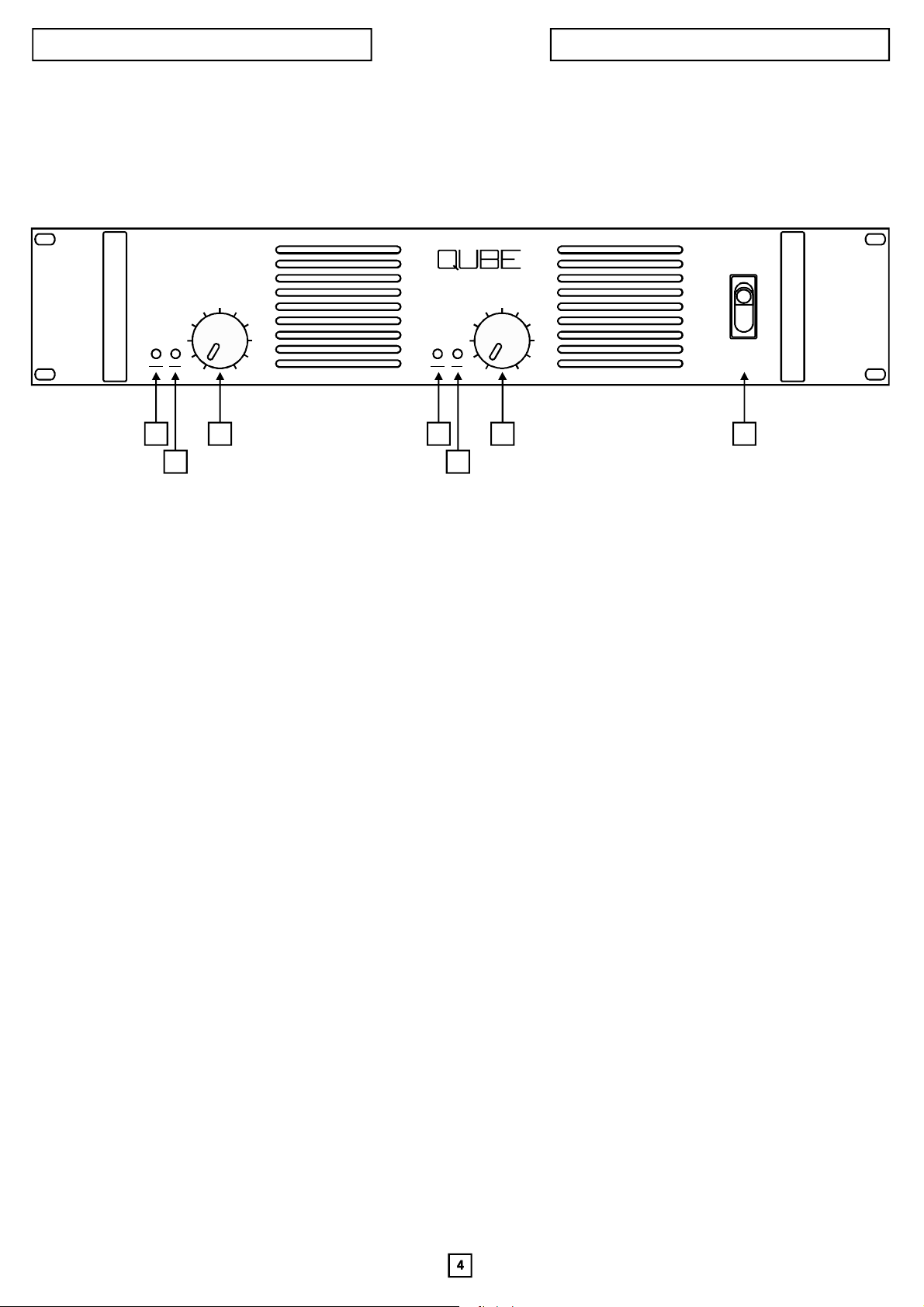
FRONTPANELFEATURES
PA140
PA140
CH.2
SIG
PROT
CLIP
1
3
2
PWR
SIG
PROT
CLIP
0 100 10
1
3
POWER
4
2
1.Channelsstatus(PROT/PWR)led
Thechannel1&2statusledglowsgreentoindicatetheamplifierisonandchannelisoperatingnormally.Itglowsredto
indicatethatoneormoreoftheamplifierchannelprotectivecircuitshasbeenactivated.Theamplifiercontainsseparateovertemperature,DConoutputandshorted-loadprotectivecircuitryforeachchannel.Wheneverafaultisdetectedtheoffending
channelistemporarily“shutdown”andthestatuslightturnedredtocallattentiontotheproblem.Thechannelwillremain“off”
untilnormaloperatingconditionsarerestored.
Note:ThestatusledisalsocontrolledbytheSP12andSP22controllersandwhenoneofthesemodulesisincluded,the
statusledwillglowredwhenoneofthesemodules’protectivecircuitshasbeenactivated.
Itisnormalforthestatusledtoglowredwhentheamplifierisfirstturnedon.Itwillthenturntoasteadygreenasasignthat
channelisonandoperatingsatisfactorily.
2.Channelssignal(SIG./CLIP)led
Thesignalledindicatesthestatusoftheamplifier’schannelsignallevel.Whenitisoff(notglowing)itshowsthat nosignalis
beingreceived.Itglowsgreentoindicateanormalsignallevelandredasanindicationthatchannelisbeingdriveninto
clipping.Occasionaloperationofthered“clip”indication(flickeringoftheredlight)isanindicationofoptimumsystem
utilization.Extendedilluminationofthered“clip”indicationisasignthesystemisbeingoverdrivenandshoudbeavoided.
3.Channeloutputattenuator
Thechanneloutputattenuatorcontrolsthegainofchannelinalloperatingmodes.Whenitisturnedfullyclockwise, the
amplifierwillhaveitsmaximumratedvoltagegainandwilldeliveritratedoutputwhendrivenbyitsratedinputsignal.Asa
generalrule,settingtheattenuatorinthefullclockwisepositionprovidesmaximumamplifierheadroom;settingthe
attenuatorsatalowerlevelmaximizesthesystemsignal/noiseratio.
Important:Whentheamplifierisbeingoperatedinthebridgeoutputmode,boththechannel1andchannel2attenuatorsmust
besetinthesamepositiontoavoidamismatchinthesignallevelbeingsenttoeachchannel.
4.Poweron/offswitch
Thisswitchisusedtoturnpowertotheamplifier“on”and“off”
 Loading...