


BASE MICROFONICA / MICROPHONE STAND
MB-T 8004
MB-T 8001 |
MB-T 8008 |
MANUALE DI ISTRUZIONI
OPERATING MANUAL
FBT ELETTRONICA S.p.A. - ZONA IND.LE SQUARTABUE - 62019 RECANATI (MC) - ITALY TEL. 071750591 r.a. - FAX 0717505920 - P.O. BOX 104 - E-mail : info@fbt.it - www.fbt.it

16113#06/10/05
Le informazioni contenute in questo manuale sono state scrupolosamente controllate; tuttavia non si assume nessuna responsabilità per eventuali inesattezze. La FBT Elettronica S.p.A si riserva il diritto di modificare le caratteristiche tecniche ed estetiche dei prodotti in qualsiasimomento e senza preavviso.
All information included in this operating manual have been scrupulously controlled; however FBT is not responsible for eventual mistakes. FBT Elettronica S.p.A. has the right to amend products and specifications without notice.

I |
INDICE |
UK |
INDEX |
INDICE - INTRODUZIONE |
|
1 |
INDEX - INTRODUCTION |
|
1 |
AVVERTENZE / APERTURA BASE |
|
2 |
WARNING / STAND OPENING |
|
2 |
MBT 8008 / MBT 8004 / MBT8001 : CONTROLLI & FUNZIONI |
|
3 |
MBT 8008 / MBT 8004 / MBT 8001 |
: CONTROLS & |
|
MBT 8008 / MBT 8004: VISTAINTERNA |
|
4 |
FUNCTIONS |
|
3 |
MBT 8001: VISTAINTERNA |
|
5 |
MBT 8008 / MBT 8004: INTERNAL VIEW |
|
4 |
ESEMPI DI COLLEGAMENTO |
6 |
- 10 |
MBT 8001: INTERNALVIEW |
|
5 |
ESEMPI DI IMPIEGO |
11 |
- 16 |
CONNECTION EXAMPLES |
6 |
- 10 |
SCHEMAABLOCCHI |
|
17 |
EMPLOYMENT EXAMPLES |
11 |
- 16 |
SPECIFICHE TECNICHE |
|
18 |
BLOCK DIAGRAM |
|
17 |
IMPIANTI |
19 |
- 22 |
TECHNICALSPECIFICATIONS |
|
18 |
SISTEMI PUBLIC ADDRESS |
23 |
- 24 |
SYSTEMS |
19 |
- 22 |
EMERGENZA |
|
25 |
PUBLIC ADDRESS SYSTEMS |
23 |
- 24 |
|
|
|
EMERGENCY |
|
25 |
INTRODUZIONE |
INTRODUCTION |
FBT Audio Contractor propone diversi modelli di basi microfoniche, corredate di flessibile e interruttore, con o senza pulsanti di selezione zone o attivazione emergenza.
Si contraddistinguono per l’elevata sensibilità e l’ampia risposta in frequenza e le capsule microfoniche sono caratterizzate da un diagramma polare cardioide.
Le basi sono corredate di un funzionale interruttore a tre posizioni, ON stabile, OFF, ON momentaneo, e di un tasto per l’attivazione dell’emergenza.
I modelli MBT8004,MBT8008, MBT8001 sono basi da tavolo preamplificate, dotate di compressore di dinamica per assicurare un elevato grado di intelligibilità, con un generatore di messaggi interno per la segnalazione di inizio e fine messaggio microfonico e per un segnale di emergenza , che, all’occorenza, può essere personalizzato in base alle specifiche richieste di impianto.
Inoltre le basi MBT consentono di selezionare 4 o 8 zone singolarmente, a secondo del modello, per annunci selettivi in ciascuna di esse, oltre al tasto per l’abilitazione della chiamata generale. A richiesta può essere realizzata una versione per il controllo di più zone.
FBT Audio Contractor proposes a range of desk microphones, with flexible goose-necks and switch, with or without area selection or emergency buttons.
These models are characterised by their high sensitivity and broad frequency response; the transmitter capsule features a cardioid polar diagram.
The microphone bases are fitted with a practical 3-position switch (ON fixed, OFF, ON temporarily) and an emergency ON button.
Both MBT8004, MBT8008, MBT8001 models are preamplified, equipped with dynamic compressor to ensure a high degree of intelligibility, with an internal message generator to mark the beginning and end of the microphone message and for an emergency signal (which if necessary can be customised to the system specifications).
MBT desk microphones can select 4 or 8 individual zones (depending on the model) for selective announcements, as well as a button to enable general announcements. On request, a v e r s i o n c o n t r o l l i n g m u l t i p l e z o n e s simultaneously can also be supplied.
1
I |
AVVERTENZE |
UK |
WARNING |
°Per prevenire fastidiosi disturbi evitate di posizionare la base in prossimità di trasformatori di alimentazione, apparecchi TV, motori elettrici, apparecchiature per il controllo dell’intensità luminosa e relativi cavi di connessione delle lampade
°Evitare di orientare i microfoni nella direzione delle casse acustiche: potrebbero generare fastidiosi inneschi che danneggerebbero gli altoparlanti.
°Assicurarsi che il cavo non sia schiacciato da oggetti e che non sia danneggiato.
°Non forzare i tasti dei comandi, sono progettati per essere sottoposti ad una leggera pressione
°To prevent annoying sound distortion, position the microphone well clear of power transformers, television sets, electric motors, lighting intensity controls and connecting lines.
°Do not turn microphones towards loudspeakers: this could cause feedback and damage to the speakers.
°Ensure that power lines are not crushed or damaged by heavy objects.
°Do not force control buttons down; always press them lightly.
IMPORTANTE |
IMPORTANT NOTES |
Per il collegamento della base rivolgersi a personale qualificato, che permetta di realizzare correttamente le connessioni e prevenire i pericoli dell’elettricità
Prima di collegare e utilizzare l’apparecchio leggete attentamente le istruzioni contenute in questomanuale.
L’errata installazione dell’apparecchiatura esime la FBT da ogni responsabilità.
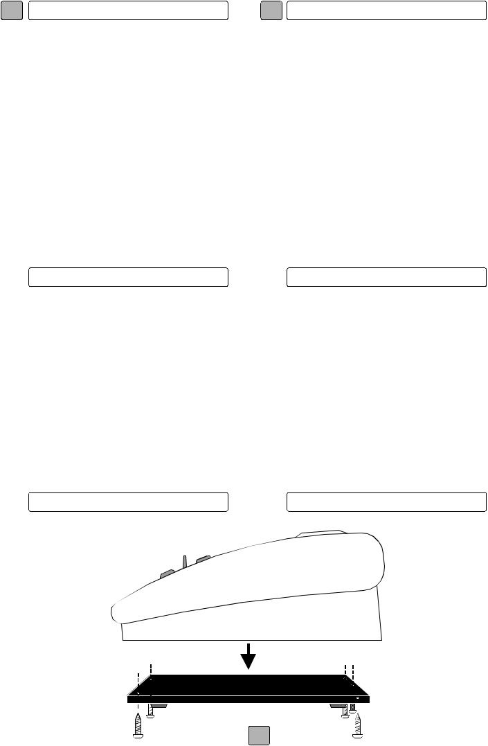
APERTURA BASE
When connecting microphones, seek the assistance of a qualified electrician, who will ensure that connections have been made properly and that all electrical risks have been eliminated.
Read the instructions contained in this manual carefully before connecting and using the appliance.
FBT declines all responsibility for incorrect installation of the appliance.
STAND OPENING
2

I |
CONTROLLI E FUNZIONI |
UK |
CONTROLS AND FUNCTIONS |
MB-T 8008 |
MB-T 8004 |
|
MB-T 8001 |
|
|
|
|
|
|
|
|
|
|
|
|
|
|
|
|
|
Mic |
6 |
|
|
|
|
|
|
Mic |
6 |
|
Mic |
6 |
Emg. |
5 |
6 |
7 |
8 |
|
|
Emg. |
|
|
|
|
|
|
Emg. |
|
|||
|
|
|
|
|
Lock |
|
|
|
|
|
|
|
Lock |
|
|
|
Lock |
|
All |
1 |
2 |
3 |
4 |
Off |
|
|
All |
1 |
2 |
3 |
4 |
Off |
|
|
|
Off |
|
|
|
|
|
|
Mom |
|
|
|
|
|
|
|
Mom |
|
|
|
Mom |
|
3 |
2 |
4 |
|
1 |
3 |
2 |
|
4 |
1 |
3 |
|
|
1 |
||||
|
|
|
|
|
|
5 |
|
|
|
|
|
5 |
|
|
|
|
5 |
|
|
|
|
|
|
|
|
|
|
|
|
|
|
|
|||
|
|
|
|
|
|
|
|
|
|
|
|
||||||
|
|
|
|
|
|
|
|
|
|
|
|
||||||
|
|
|
|
|
|
|
|
|
|
|
|
||||||
|
|
|
|
|
|
|
|
|
|
|
|
|
|
||||
|
|
|
|
|
|
|
|
|
|
|
|
|
|
|
|
|
|
1] LOCK/OFF/MOM - Interruttore a tre posizioni; nella posizione centrale (off) la base è disattivata; nella posizione LOCK l’interruttore è stabile; nella posizione MOM la base è attivata momentaneamente finchè il tasto non viene rilasciato.
2] ALL - La funzione ALL permette la diffusione di un annuncio in tutte le zone audio del sistema, interrompendo l’eventuale musica di sottofondo. Il relativo led indica l’attivazione della funzione.
3] EMG - Questa funzione permette di attivare l’emergenza su tutte le apparecchiature che compongono il sistema e di inviare il segnale predisposto in memoria. Il segnale di emergenza può essere personalizzato in base alle specifiche richieste di impianto. Il led indica l’attivazione della funzione.
4] 1/2/3/4 - Tasti per la selezione delle zone in cui dovrà essere diffuso l’annuncio microfonico con priorità sulla musica . L’accensione del led indica l’attivazione della funzione..
5] Flessibile con capsula microfonica di tipo electrete con curva polare cardioide; si contraddistingue per le ottime caratteristiche di riproduzione della voce, minima distorsione e buona sensibilità.
6] Mic  - Led di monitoraggio che visualizzano il tipo di segnale presente in uscita (microfonico o segnale memorizzato).
1] LOCK/OFF/MOM Three-position switch; set to the central position (OFF) to turn the microphone off; set to LOCK to keep the switch in a stable position; set to MOM to deactivate the microphone temporarily (until the button is released).
2] ALL - The ALL function is used to broadcast announcements to all system areas while silencing background music. The LED lamp indicates when the function is on.
3] EMG Use this function to activate the emergency mode on all system appliances and to broadcast a memorised signal. The signal can be customised according to system requirements. The LED lamp indicates when the function is on.
4] 1/2/3/4 Buttons for the selection of announcement broadcast areas (overriding background music). The LED lamp indicates when the function is on.
5] Goose-neck and electret microphone with cardioid polar pattern; designed for optimal pure voice reproduction, minimal distortion and good sensitivity.
6] MIC  -Monitoring LED lamp indicating output signal type (microphone or memorised signal).
3
I
CONTROLLI E FUNZIONI UK CONTROLS AND FUNCTIONS
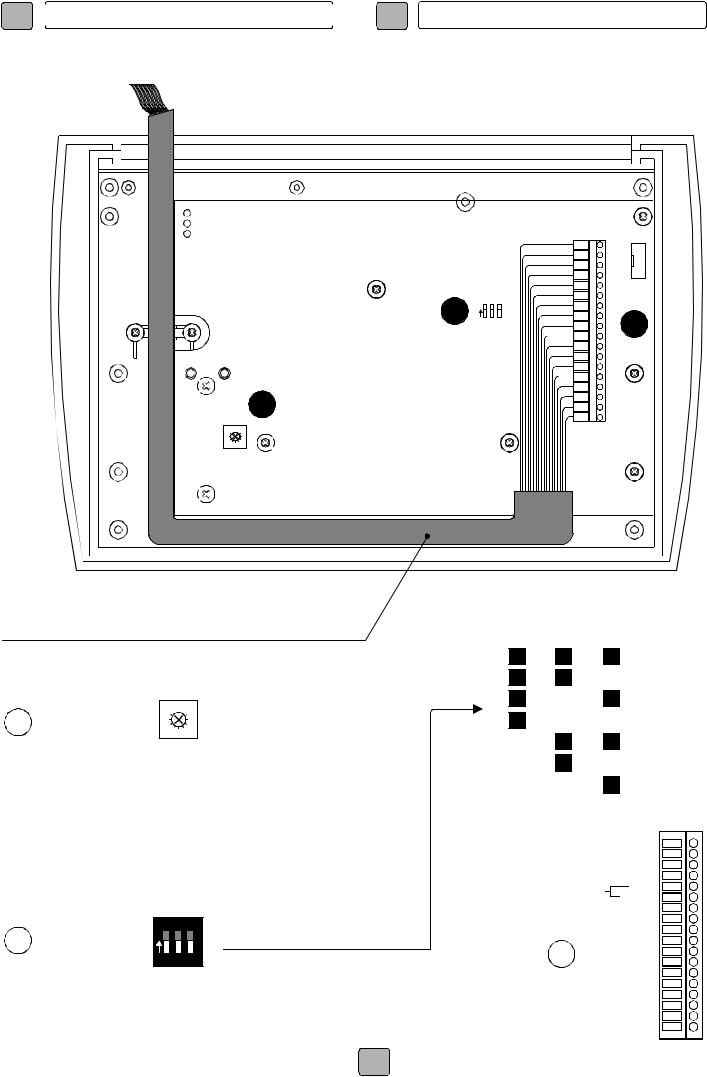
VISTA INTERNA / INTERNAL VIEW
MB-T 8008
MB-T 8004
|
|
|
1 |
|
|
|
|
|
2 |
|
|
|
|
|
3 |
|
|
|
|
|
4 |
|
|
|
|
|
5 |
GROUND |
|
8 |
|
|
|
6 |
|
1 |
2 |
3 |
8 |
|
|
|
N |
|
|
7 |
9 |
|
|
|
|
9 |
|
|
|
|
|
||
|
|
|
10 |
|
|
|
|
|
11 |
|
|
|
|
|
12 |
|
|
|
13 |
|
|
14 |
|
7 |
15 |
|
16 |
||
17 |
||
|
||
|
18 |
SOUND GAIN
ATTENZIONE: PER IL COLLEGAMENTO DEL CAVO RIVOLGERSI A PERSONALE QUALIFICATO.
IMPORTANT: FOR LINE CONNECTIONS SEEK THE ASSISTANCE OF A QUALIFIED ELECTRICIAN
7
SOUND GAIN
Regola il volume del segnale di preavviso da inviare nelle varie zone.
Il potenziometro è situato all’interno della base, quindi va tarato al momento dell’installazione.
CONFIGURAZIONE SEGNALI DI PREAVVISO
PRE AND POST ANNOUNCEMENT CHIME
1 |
2 |
3 |
CHIME |
||
START |
STOP |
||||
|
|
|
|||
|
|
|
NO |
NO |
|
|
|
ON |
MSG1 |
NO |
|
|
|
|
|
|
|
|
ON |
|
MSG1 |
MSG1 |
|
|
ON |
ON |
MSG1 |
MSG2 |
|
ON |
|
|
MSG2 |
NO |
|
ON |
|
ON |
MSG2 |
MSG1 |
|
ON |
ON |
|
MSG2 |
MSG2 |
|
ON |
ON |
ON |
NO |
NO |
|
|
|
|
|
|
|
Adjusts the alert signal volume to broadcast in selected areas. The potentiometer is located inside the base, and must therefore be calibration during installation.
1 2 3
8 |
N |
|
DIP switch per la configurazione dei segnali di preavviso (vedi tabella )
DIP switch for configuration of alert signals (see table)
|
|
GND |
1 |
|
|
|
+15V |
2 |
|
|
|
GND |
3 |
|
|
|
-15V |
4 |
|
SIG. OUT |
HOT |
5 |
||
COLD |
6 |
|||
|
|
|||
|
MUSIC OFF |
7 |
||
|
|
ZONE1 |
8 |
|
|
|
ZONE2 |
9 |
|
9 |
|
ZONE3 |
10 |
|
|
ZONE4 |
11 |
||
|
ZONE5 |
12 |
||
|
|
ZONE6 |
13 |
|
|
|
ZONE7 |
14 |
|
|
|
ZONE8 |
15 |
|
|
EMERGENCY |
16 |
||
|
PRIORITY1 |
17 |
||
|
PRIORITY2 |
18 |
||
4 |
COLLEGAMENTI MORSETTIERA |
|
TERMINAL STRIP CONNECTIONS |
||
|

I
CONTROLLI E FUNZIONI
VISTA INTERNA / INTERNAL VIEW
UK CONTROLS AND FUNCTIONS
MB-T 8001
CAVO MICROFONICO CON XLR-M
+ 2 CONDUTTORI DI CONTATTO LOGICO
MICROPHONA CABLE WITH XLR-M + 2 LOGIC CONDUCTORS
ON
8
1 2 3
ATTENZIONE: PER IL COLLEGAMENTO DEL CAVO
RIVOLGERSI A PERSONALE QUALIFICATO.
IMPORTANT: FOR LINE CONNECTIONS SEEK THE
ASSISTANCE OF A QUALIFIED ELECTRICIAN
7 


1 |
|
2 |
9 |
3 |
4
5
6
7
8
9
10
11
12
13
14
15
16
17
18
7 |
9 |
CHIME GAIN
Regola il volume del segnale di preavviso.
Il potenziometro è situato all’interno della base, quindi va tarato al momento dell’installazione.
Adjusts the alert signal volume to broadcast in selected areas. The potentiometer is located inside the base, and must therefore be calibration during installation.
1 2 3
8 N 


DIP switch per la configurazione dei segnali di preavviso (vedi tabella )
DIP switch for configuration of alert signals (see table)
CONFIGURAZIONE SEGNALI DI PREAVVISO
PRE AND POST ANNOUNCEMENT CHIME
1 |
2 |
3 |
CHIME |
||
START |
STOP |
||||
|
|
|
|||
|
|
|
NO |
NO |
|
|
|
|
|
|
|
|
|
ON |
MSG1 |
NO |
|
|
ON |
|
MSG1 |
MSG1 |
|
|
ON |
ON |
MSG1 |
MSG2 |
|
ON |
|
|
MSG2 |
NO |
|
ON |
|
ON |
MSG2 |
MSG1 |
|
ON |
ON |
|
MSG2 |
MSG2 |
|
ON |
ON |
ON |
NO |
NO |
|
|
|
|
|
|
|
|
GND |
1 |
|
|
+15V |
2 |
|
|
GND |
3 |
|
|
-15V |
4 |
|
SIG. OUT |
HOT |
5 |
|
COLD |
6 |
||
|
|||
MUSIC OFF |
7 |
||
|
|
8 |
|
|
|
9 |
|
|
|
10 |
|
|
|
11 |
|
|
|
12 |
|
|
|
13 |
|
|
|
14 |
|
EMERGENCY |
15 |
||
16 |
|||
PRIORITY1 |
17 |
||
PRIORITY2 |
18 |
||
COLLEGAMENTI MORSETTIERA
TERMINAL STRIP CONNECTIONS
5

I |
ESEMPI DI COLLEGAMENTO |
UK |
CONNECTION EXAMPLES |
MZU2008
ALL |
8 7 6 5 4 3 2 1 |
IN/OUT |
|
HOT COLD SHIELD PRIORITY NC |
CODE 12701 MZU 2008 |
A K GND PWR |
COLL |
|
+15 0 -15 |
|
CALL REMOTE ZONE CONTROLS |
SIGNAL |
|
EMERGENCY |
|
|
POWER I max 100mA |
|
MADE IN ITALY |
||
|
|


 PRIORITY
|
|
GND |
1 |
|
|
|
|
|
+15V |
2 |
|
|
|
|
|
GND |
3 |
|
|
|
|
|
-15V |
4 |
1 |
2 |
3 |
|
SIG. OUT |
HOT |
5 |
|||
|
|
|
|
|||
|
COLD |
6 |
|
|
|
|
|
|
|
|
|
||
|
MUSIC OFF |
7 |
|
|
|
|
|
|
ZONE1 |
8 |
|
|
|
|
|
ZONE2 |
9 |
|
U10 |
|
|
|
ZONE3 |
10 |
|
|
|
|
|
ZONE4 |
11 |
|
|
|
|
|
ZONE5 |
12 |
|
|
|
|
|
ZONE6 |
13 |
|
|
|
|
|
ZONE7 |
14 |
|
|
|
|
|
ZONE8 |
15 |
|
|
|
|
EMERGENCY |
16 |
|
|
|
|
|
PRIORITY1 |
17 |
|
|
|
|
T3 |
PRIORITY2 |
18 |
|
|
|
|
|
|
|
|
|
|
|
SOUND GAIN |
COLLEGAMENTI MORSETTIERA |
|
|
|
||
TERMINAL STRIP CONNECTIONS |
|
|
|
|||
MBT 8008
6

I |
ESEMPI DI COLLEGAMENTO |
UK |
CONNECTION EXAMPLES |
CODE 11825 MCA 4240
RISK OF ELECTRIC SHOCK
DO NOT OPEN
TO REDUCE THE RISK OF ELECTRIC SHOCK DO NOT REMOVE COVER (OR BACK) NO USER SERVICEABLE PARTS INSIDE REFER SERVICING TO QUALIFIED SERVICE PERSONNEL
PWR OUT 4 |
PWR OUT 3 |
min max min |
max |
4 |
3 |
CHANNEL REMOTE VOLUME
|
EMERGENCY COM |
LINE |
EMERGENCY COM |
LINE |
15V |
PRT |
|
|
|
|
|
IN |
|
|
OUT |
|
|
INPUT B |
|
|
|
PRIORITY |
|
|
PWR LOAD S/W GND |
PWR COLLECT |
HOT COLD SHIELD |
|
|
15V |
|||||||||
230 V |
VOLUME |
|
T 6 A 250 V |
||
|
Made in Italy
MCA 4240A
|
|
5 |
|
0 |
10 |
|
CH 4 |
|
HOT COLD SHIELD |
LOAD |
HOT COLD SHIELD +15V 0 -15V |
SIGNAL |
|
INPUT A |
FAILURE
AMPLIFIER MCA4240A
FROM
MIXER
|
|
GND |
1 |
|
|
|
|
|
+15V |
2 |
|
|
|
|
|
GND |
3 |
|
|
|
|
|
-15V |
4 |
1 |
2 |
3 |
|
SIG. OUT |
HOT |
5 |
|||
|
|
|
|
|||
|
COLD |
6 |
|
|
|
|
|
|
|
|
|
||
|
MUSIC OFF |
7 |
|
|
|
|
|
|
ZONE1 |
8 |
|
|
|
|
|
ZONE2 |
9 |
|
U10 |
|
|
|
ZONE3 |
10 |
|
|
|
|
|
ZONE4 |
11 |
|
|
|
|
|
|
12 |
|
|
|
|
|
|
13 |
|
|
|
|
|
|
14 |
|
|
|
|
EMERGENCY |
15 |
|
|
|
|
|
16 |
|
|
|
||
|
PRIORITY1 |
17 |
|
|
|
|
T3 |
PRIORITY2 |
18 |
|
|
|
|
|
|
|
|
|
|
|
SOUND GAIN |
COLLEGAMENTI MORSETTIERA |
|
|
|
||
TERMINAL STRIP CONNECTIONS |
|
|
|
|||
MBT 8004
7
 Loading...