

Faw J6p User Manual

TCE I / II
Central Electronic in
Trailers
815 000 375 3
2nd Edition
This publication is not subject to any update service.
New versions are available in INFORM at
www.wabco-auto.com
815 000 329 3
8150003293
© 2007 WABCO
Vehicle Control Systems
The right of amendment is reserved
Version 002/11.03(en)
8150100303 815 010 030 3

Table of contents
1 Objective
1.1 Concept and Implementation 4
2 General
2.1 External Communication Possibilities 5
2.2 Standards 6
3 Line connection Description
3.1 Functional overview 7
3.2 Electronics 446 122 00. 0 8
3.2.1 TCE top view with connector coding 9
3.3 System connections 10
4 Cable Overview 22
4.1 TCE connection system with connecting cable and PIN connection 15
4.1.1 Overview of plug-in connectors and corresponding cables 15
5 System Functions (acc. to terminals)
5.1 Brake lining wear indicator 37
5.2 Electrical Supply 39
5.2.1 Standardised motor vehicle plug-in connections 39
5.2.2 Supply 40
5.3 Diagnosis mode and warning light function 41
5.3.1 Gateway ISO 7638 / ISO 12098 Trailer data bus 41
5.3.2 warning light function 42
5.4 Freely programmable I/O (special modules) 42
5.4.1 Monitoring functions 42
5.5 Trailer EBS and RGE connection 42
5.5.1 Trailer EBS 42
5.5.2 RGE connection 43
5.6 Rear underdrive protection terminal 44
5.7 Ramp approach help 44
5.8 Paver brake 46
5.9 Electronically controlled air suspension (ECAS) in TCE 46
5.9.1 Components 47
5.9.2 Distance sensor(s) and trailer battery 51
5.10 Pneumatic components and installation instructions 57
6 Commissioning and Diagnosis 82
6.1 Commissioning and Diagnosis 59
6.1.1 The Calibration Process 59
7 PC - Diagnosis 23
7.1 Start- and diagnostic menu 62
7.2 Vehicle definition 63
7.2.1 Chassis & lighting 64
7.2.2 Special parameters 65
7.2.3 ECAS parameters 66
7.3 Special parameters 67
7.4 Axle load calibration 72
7.5 Switch positions / Outputs 72
7.6 Service management 73
7.7 System plate 73
7.8 End Of Line - Protocol 74
8. Annex 77
8.1 Abbreviations 78
8.2 Overview of Outline Drawings 79
2

Objective
TCE
1
In modern motor vehicles the onboard information for
drivers becomes more and more extensive. In future
drivers will be able to read information about truck and
trailer via a display on their dashboard They will get this
information via data buses, i.e. via communication
connections between different electronics having a CAN
interface. As a result the connected electronic systems
will be able to exchange, evaluate and further process
information. In future lighting on vehicles will also be
controlled via data buses and errors will be displayed in
trucks.
Trailers will be included in this exchange of information
via a 7-pin ABS/EBS plug connection acc. to ISO 7638
and in parallel via a 15-pin plug connection acc. to
ISO 12098. In both cases the data connection
corresponds to ISO 11992 part 1.
By a consequent use of the available data connections
between motor vehicle and trailer WABCO creates the
precondition for new innovative vehicle functions while
at the same time the number of the required electrical
connections is limited.
In summary the objectives are as follows:
System data bus in trailers
Integration of trailers into the motor vehicle
system
• Limitation of number of electrical connections
• Extension of the motor vehicle system functions
to trailers
Integration of trailer system functions
• Level control and lifting axle control
• Ramp approach help
• Lighting control
• Telematic connection
• Additional functions
TCE II
Modifications due to the introduction of TCE II are
marked in the following text in expanded type.
• New trailer system functions via data exchange
• More simple realisation of current system
functions
Telematics
Power 7 Pin ISO 7638
Power 15 Pin ISO 12098
IVTM - Integrated
Vehicle Tire
Monitoring system
TCE
ECAS
wear
Customer
functions
approach help
Lighting
Ramp
CAN
Trailer
Data
Diagnosis
EBS modulator
BUS
Brake lining
3

1
TCE
Objective
1.1 Concept and Realisation
As trailer central electronic TCE enables the
communication between motor vehicle and trailer res.
motor vehicle and trailer systems. Moreover TCE
supports the connection of intelligent individual systems
in trailers to a powerful system like in the towing vehicle.
TCE itself assumes the following electronic and
electrical functions:
Electrical supply of trailer systems including battery
supply and battery charging equipment. With a trailer battery diagnostic and ramp operations are possible without a motor vehicle.
Motor vehicle - trailer communication for brake and
”running gear“ systems (ISO 7638), as well as for
general vehicle systems (ISO 12098). ”Running
gear“ means components concerning the driving
safety, e.g. chassis, tires, steering and suspension.
Trailer data bus for EBS, running gear, tire systems
and vehicle systems with separate CAN connections. As a result an exchange of electrical consumers and transmission of information via data
connection is possible.
Future central diagnostic connection for TCE and
all systems connected via CAN. Future diagnosis
from the motor vehicle is provided (e.g. via an onboard display).
Brake lining wear sensing system with up to six
sensors.
In future reading and processing of analogue and
digital information will be possible.
e.g.
Programmable inputs and outputs for recording of
switch positions and analogue values, as well as for
controlling modulators and additional lighting. Individual customer modules will be created by
WABCO. These are adjustable via diagnosis.
Integrated electronic level control (ECAS) for semi-
trailers and trailers with one or two level sensors.
Integrated electronic lift axle control with automatic
functions as traction help, load dependent lowering
/ lifting and manoeuvring aid.
Ramp approaching help with automatic braking
when backing and approaching the ramp.
Electronically secured lighting control and monitor-
ing with status reports to the motor vehicle.
tire pressure recording and tire pressure monitoring
with connected IVTM system.
Service support (operating hours counter, mileage
counter, electronic notebook, battery hours counter).
ISO 7638 (5/7-pin.)
Green warning light
ISO 12098 (15/7-pin.)
Side marking and limiting lights
Diagnostic plug EBS
ABS wheel sensors
EBS
LA-Ventil
LF-Vent i l
DSENS
EBS
ABS wheel sensors
Brake lining wear sensors
DSENS2
WSENS2
WSENS1
DSENS1
Trailer battery
Brake lining wear sensors
Ultra sonic sensors
TCE
IVTM
BAT
Ultra sonic
sensor
Diagnostic
plug TCE
Remote remote control unit
4

General
)
TCE
2
The following data can be transmitted to the motor
vehicle provided the respective system is installed:
• Axle loads:
• Tire pressure values
• Status of vehicle lighting
• Distance to ramp
• Brake lining wear
• Status of ramp approach help RAH
• Lift axle status
Under same conditions as in the motor vehicle the
following data can be transmitted to a telematic system:
• Error in lighting
• Error in RAH function
• Vehicle stopped before ramp
• Service date achieved
• Vehicle overloaded
• Red /yellow/green warning light
• Axle load
• Tire pressure values
• Error in RAH function
• Vehicle hitched/unhitched
• Battery status
• Vehicle door open/closed
• Operating hours
• Mileage
• Brake lining wear
2.1 External Communication
Possibilities
When a telematic system is connected to the TCE
location of the vehicle resp. recall of vehicle specific data
is possible.
The following transmission systems can be used:
The Global Positioning System, shortly called
GPS, enables identification of the vehicle position.
The Global System for Mobile Communication
(GSM) enables wireless data transmission. Thus
remote diagnosis will also be possible in future.
The 'Short Range Communication' is only possible
in the yard near a correspond. transmitting / receiving station.
Satellite
Satellite
GPS
Global Positioning System
Short wave
Communication
(Blue Tooth, DECT, ..)
Local Server
Carrier owner
Fleet owners
Satellite
Satellite
GSM
Global System for
Mobile Communication
(D1, D2, ...)
z
h
M
0
0
9
z
h
M
0
0
8
1
z
h
M
z
3
h
3
4
M
8
6
8
Telecommunications
Company
ISDN
Internet
(TCP/IP)
Fleet Management
Carrier Park Management
Services Provider
WWW Server
Satellite Antenna
Data
5

2
TCE
General
The different systems may be used from trucks with
trailer connection or separately on trucks and on trailers
(e.g. for cooler and service information).
Thus the carrier resp. the controller can check for
instance position of the vehicle, temperature of the
cooling system and state of the vehicle. On short term
he may have the vehicle turned around and pick up
another load. In case of vehicle problems the controller
can inform a nearby repair shop in advance about the
vehicle state and can care for spare parts if required.
Telematic problems can only be corrected by the
respective telematic manufacturer in his service
repair shops.
2.2 Standards
TCE observes the following standards:
TCE II
Telematic systems in trucks and trailers can retrieve
more special information from the TCE II.
– event and profile data
– Service schedule
– Vehicle master data
Telematic systems in trailers will automatically be
informed on additional events
– Vehicle door open/closed
– Vehicle hitched/unhitched
– Tire pressure changes
– Service intervals etc.
– ISO 11992 defines data interfaces
between motor vehicles and trailers
• Part 1: Exchange of digital data between truck
and trailer
• Part 2: Application for brake and ”running gear“
of part 1
• Part 3: Application for all further systems of part
1 which were not considered in part 2
• Part 4: Diagnosis (in preparation)
– ISO 7638, 7-pin electrical truck-trailer
connection for braking and running gear
systems
• Chassis, tires and brake
• Use for lighting, superstructure control or similar
is expressly excluded.
– ISO 12098, 15-pin electrical truck-trailer
connection for lighting and superstructure
• Lighting, conventional lifting and steering axle
control
• Electrical supply and data connection for non
braking and ”running gear systems“
– Brake directive ECE-R13
• Supply of braking and running gear equipment
• Cut-off of running gear systems / Functions at
electrical overload
6

Line connection Description
3.1 Functional overview
Note:
TCE I/II is already fully operational, when except
connection to the motor vehicle only the EBS system is
connected, i.e. Ramp approaching help, ECAS, lighting,
tire pressure control and GPS/GSM do not need to be
installed resp. connected.
Bremse / Fahrwerk
Brake/running gear
Ramp approaching help
Rampenanfahrhilfe
TCE
3
Anhänger-
Trailer
+
batterie
battery
EBS
Brake lining wear sensors
Bremsbelagverschleißsensoren
ISO 7638 (7-pol.)
ISO 7638 (7-pin)
ISO 12098 (15-pol.), alternativ 24N/S
ISO 12098 (15-pin) alternative 24N/S
Diagnose
Diagnosis
IVTM
System zur Reifendrucküberwachung
TCE
TCE-
warning light
Warnlampe
(Integrated Vehicle Tire Monitor)
RGE input and output
RGE Ein- und Ausgangs-
expansion (control box)
erweiterung
RGE CAN Expansion
RGE CAN-Erweiterung
(Telematic connection)
(Telematikanschluss)
(Bedienbox)
TCE
X11
X12
X13
X14 X34X24
X31X21
X22 X42
X32
X23 X33
X41 X61
X43 X63X53
X44 X64X54
X51
X52
Pressure sensors
U
P
U
Operating
Bedienei nheit(en)
interfaces
Wegsensor(en)
Path sensors
X62
Not
occupied
Solenoid
Magnetventile
valves
Drucksensor(en)
P
Magnetventil für
Solenoid valve
Liftachssteuerung
for Lifting axle
control
Nicht
belegt
Verteiler
Lighting/superstructure systems
Beleuchtung / Aufbausysteme
Superstructure system -CAN Expansion
Aufbausystem - CAN-Erweiterung
Superstructure -additional lighting, Additional
Aufbau - Zusatzbeleuchtung, zusätzl. elektr.
Versorgung und Ein- und Ausgänge
electrical supply and Inputs and outputs
7
3
TCE
Line connection Description
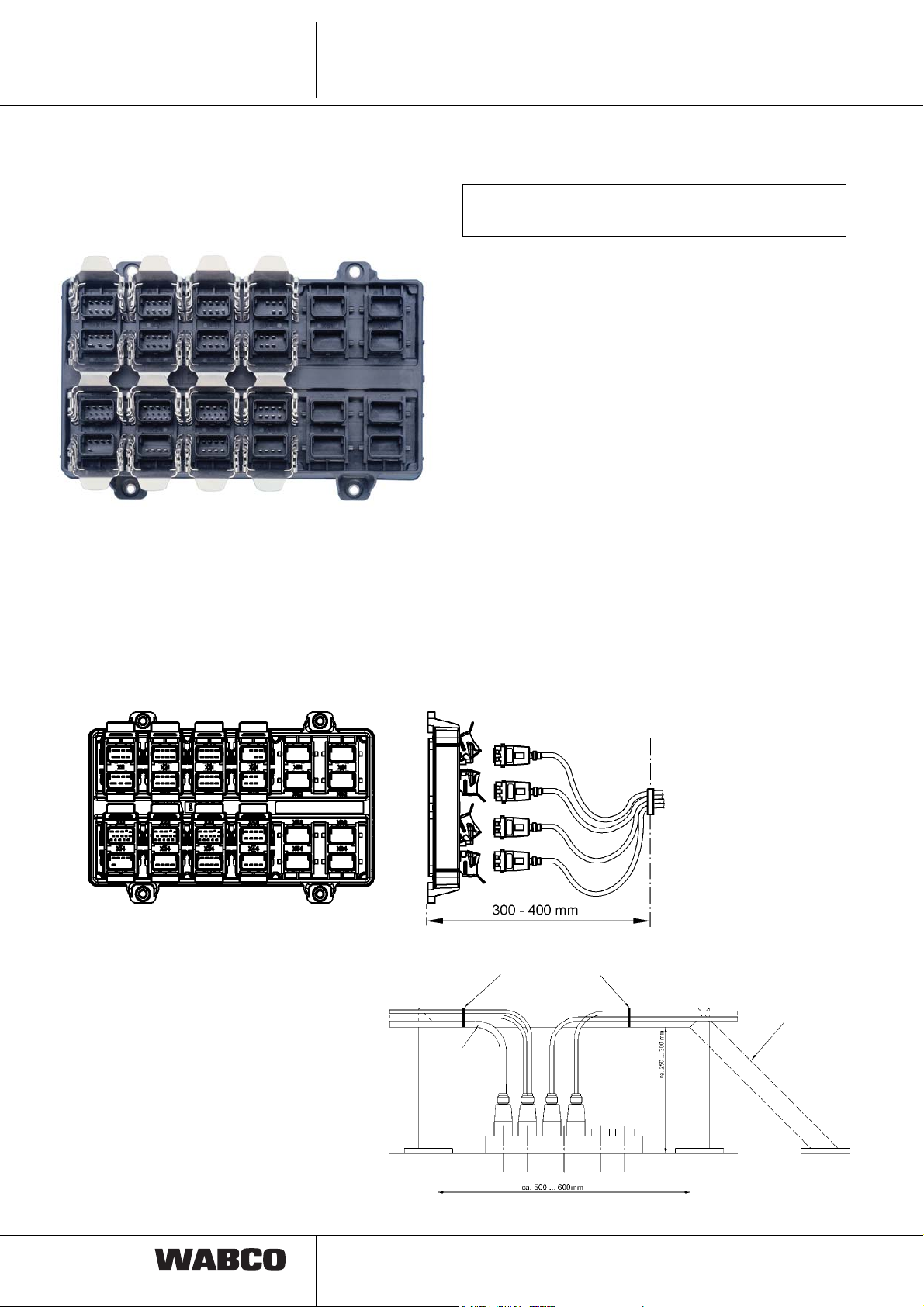
3.2 Electronic 446 122 000 0 /
446 122 001 0
Do not open the electronic remote control unit!
All terminals have to be closed.
All plug in connections are marked with an X and a
number and fitted with special locking clips. To connect
a cable, it is necessary to fold up the locking clip, push
in the plug and then close the locking clip.
Since the terminals are located very close, cables
should be plugged into the electronic in the order from
X11 to X41, X12 to X42, etc.
The front of the electronic consists of coded plug-in
terminals and thus is protected against interchange of
plugs. Unused terminals have to be closed by means of
cap 894 110 139 2.
Installation position:
Fixation to clip by means of cable binder or similar
In order to reverse the
cable back to the vehicle
frame the 45° solution
could be the better one.
Free cable
length to the
point of
fixation
approx.
300 mm
8

Line connection Description
3.2.1 TCE Top View with connector coding
TCE
3
control unit
X41-Remote remote
help
X31-Ramp approaching
X21-RGE and I/O
6 5
3 2 1
Battery
X42-Height sensor
4 3 2 1
8 7 6 5
4 3 2 1
8 7 6 5
X32-IVTM and super-
structure CAN
X22-EBS and RGE CAN
4 3 2
8 7 6
4 3 2 1
8 7 6 5
4 3 2 1
8 7 6 5
X43-Solenoid valve
lighting
X33-Superstructure
X23-Lighting
4 3 2 1
8 7 6 5
1
2
12 11
13
9 7 6
4 3
1415
10 8
5
1
2
12 11
13
9 7 6
4 3
1415
10 8
5
X44-Pressure sensor
lighting
X34-Tank vehicle
X24-Side marking
8 7 6 5
4 3 2 1
8 7 6 5
8 7 6 5
X11-Brake lining wear
1
2
12 11
13
9 7 6
4 3
7 6 5
4 3 2 1
8 7 6 5
X12-ISO 7638 (7-pin)
4 3 2 1
X13-ISO 12098 (15-pin)
1415
10 8
5
2
X14-Diagnosis and
Warning lamp
3 2 14
8
9
3
TCE
Line connection Description
3.3 System connections
TCE terminals in numeric order
1. Row
Connection X11 (optional)
Brake lining wear sensors
Connection for up to six brake lining wear sensors or up
to six wear indicators (side wire). Brake lining wear
sensors measure the thickness of the brake lining only
when braking. If wear indicators are installed, thickness
of the brake lining is actualised in braked or unbraked
condition. For example, if for all indicators 0 Volt will be
measured, connector break will be identified.
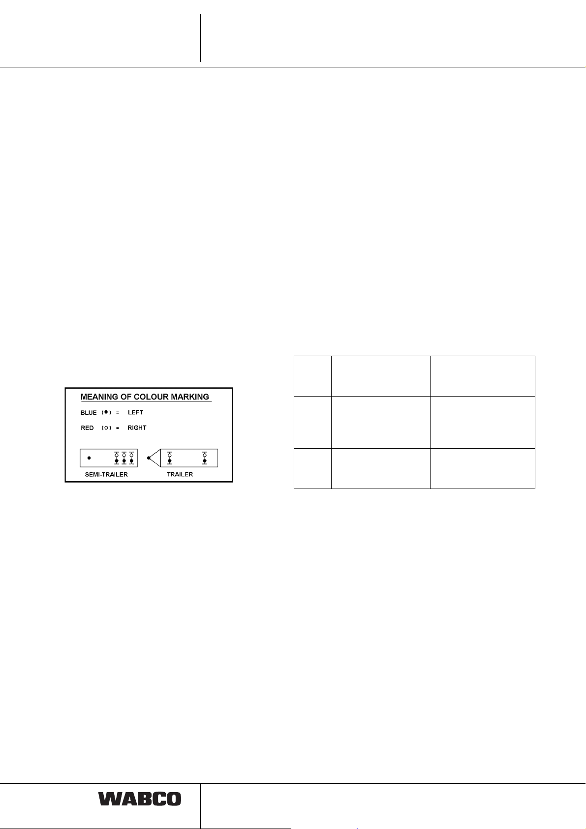
The Y cable is colour marked. Below the connector there
is a red resp. blue stripe. The red marked plug belongs
to the right vehicle side, the blue marked plug to the
left side. Furthermore the axle assignment can be found
behind the plug (L1 = 1 axle on the left).
• corresponding TCE error (e.g. failure of EBS
modulator)
• Switch on of ignition (Pin)
• Interruption of ground connection
(Pin 3 and 4).
Connection X13
Motor vehicle connection acc. to ISO 12098
(15-pin)
Connection of power supply and lighting lines with data
connection acc. to ISO 12098 (15-pin). The data bus
contains information on lighting and superstructure
systems.
Plug-in pins 10, 11 and 12 are not controlled via PC
diagnosis. These can be parameterize per PC diagnosis
by means of special modules:
Pin 10
Pin 11
Pin 12
Pin 10
Pin 11
Pin 12
Pin 10,
11, 12
Brake lining sensor
not used
Axle lift
not used / steering
axle lock
Traction help
Axle lift
not controlled
according to
ISO 12098 / 1990
according to
ISO 12098 / 2000
New standard
Standard, if no trailer
or lift axle control from
the truck desired
Connection X12
Motor vehicle connection acc. to ISO 7638
Connection motor vehicle connection 7-pins (or 5-pins,
if there is no CAN-connection) acc. to ISO 7638 with
truck-trailer data connection acc. to ISO/ 11992 part 1
and 2.
Communication truck-trailer acc. to ISO 11992.
Support of the ABS module in trucks.
Monitoring of ground connections for break
Recognition of supply under or over voltage
Recognition of overload (current and voltage
measurement) and cut-off of running gear
Systems
Active control of trailer warning light (Pin 5) at:
10
Communication truck-trailer acc. to ISO 11992.
Support of trailer recognition via flashing and/or
brake light line
Maximum input impedance ≤ 2 kOhm.
Sensing/monitoring of lighting lines
Under / over voltage recognition of electrical supply
Truck-trailer data connection acc. to ISO 11992
part 1 and 3 (only with plug connection acc. to
ISO 12098)
Freely programmable inputs and outputs (special
modules; only with plug connection acc. to
ISO 12098)
Emergency supply of EBS via brake light, if
ISO 7638 interface has failed.

Line connection Description
TCE
3
Connection X14
Diagnostic connection:
Central connection for a diagnostic tool and optional
connection for a trailer warning light (green warning
light).
Diagnostic tool connection
The electrical power is supplied from ISO 7638
Pin 30 (Pin 1). Without a towing vehicle diagnosis
is enabled with a trailer battery. Raising/lowering
per remote remote control unit is also possible in
the diagnosis mode.
Connection of a warning light
An optional green warning light can be mounted to
the vehicle.
The electrical power is supplied from ISO 7638
Pin 30 (Pin 1).
Following display info is available:
Warning light status
– flashing: Display of general TCE errors
– on: trailer vehicle not within the
normal level
– off: vehicle within normal level
and without faults or ignition
switched off.
CAN communication via trailer data bus acc. to
ISO 11898 with 250 kBaud.
In case of interferences the external CAN data con-
nections can be cut off separately.
Information to connection X23/X24/X33/X34
Trailer lighting
Vehicle lighting left/right is protected separately in the
TCE.
Note:
Errors only appear when the lighting is actuated.
Connect all lights directly to the corresponding cable.
Cables must not be shortened or lengthened!
In order to avoid malfunctions during operation, the
maximum number of consumers must be observed.
Thus installation of an additional flashing light to the
underdrive protection is not allowed! At any rate the
manufacturer specifications must be observed.
Activation, control signal and electrical supply of trailer
lighting and extension for superstructure functions are
made via plug connection acc. to ISO 12098 (15-pin).
Electronic control / protection acc. to control sig-
nals via ISO 12098.
Error detection for short circuit and interruption,
when activated.
Connection X23
2. Row
Connection X21(optional)
Extension running gear / brake
Connection of 24 V-users and/or 24 V-Sensor analysis.
Power is supplied by means of motor vehicle plug
connection acc. to ISO 7638. Functional assignment is
programmable via special modules.
Note: Since the supply is made via ISO 7638, only such
systems/components may be connected, which either
belong to the vehicle brake or belong to ”running gear“
system!
The same concerns systems/components referring to
driving security, e.g. chassis, tires, steering, suspension
Connection X22
Trailer EBS & Running Gear-Systems
Connection of Trailer EBS and of an external Running
Gear Systems.
The electrical power is supplied from ISO 7638 Pin
(pin 1) with electronic overload protection.
Standard lighting rear underdrive protection
(Performance per vehicle side)
TCE I TCE II
Brake light 21 WA 2 x 21 W
Flashing light 21 WA 2 x 21 W
Rear light 30 W 30 W
(2 x10 W Rear light +
2 x 5 W Identification
light)
Reverse
light 21 W 2 x 21 W + 2 x 70 W each
Side with freely
adjustable parameters
Rear fog
light 21W 2 x 21 W per side
with parameters
adjustable
Position
lamps 2 x 10 W 2 x 10 W or LED’s
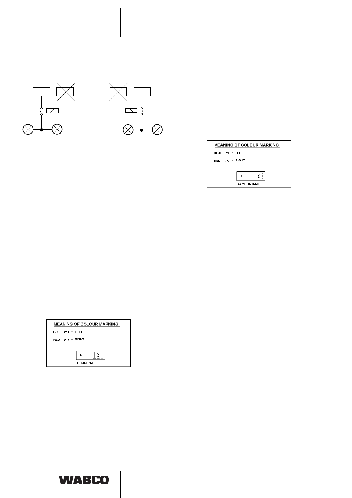
TCE I:
2 x 70 W reverse lights can be connected either to the
24 V outputs of X23 pin3 or to X33 pin 3. However, the
11
3
TCE
Line connection Description
load must only be connected to one of the plugs. A relay
is required between reverse light and the respective pin.
X23 X33 X23 X33
70 W
70 W
or
Reverse light
70 W
70 W
TCE II
Now also the connection of LED lamps to TCE II is
possible! Moreover the light failure recognition was
improved.
Via PC diagnosis the sensibility of the parameters for
cable break recognition can be set.
Standard setting: In the case of a failure of one of two
connected lights (e.g. brake light), this will not be
detected as an error.
Extended parameters: At this setting the failure of the
light with same or higher electrical power is detected.
No break recognition with light emitting diodes.
Electrical supply via separate 8 V power genera-
tion in the TCE, supplied via motor vehicle connection acc. to ISO 7638
Sending / receiving signal lines separately for each
sensor
The Y cable is colour marked. Below the connector there
is a red resp. blue stripe. The red marked plug belongs
to the right vehicle side, the blue marked plug to the
left side.
Connection X32 (optional)
Tire pressure monitoring IVTM & general vehicle
systems
Connection tire pressure monitoring and general vehicle
systems (no braking and running gear systems) with
CAN data connection.
Connection X24
Side marker lamp
The Y cable is colour marked. Below the connector there
is a red resp. blue stripe. The red marked plug belongs
to the right vehicle side, the blue marked plug to the
left side.
side marking lamps (25 W)
3. Row
Connection X31 (optional)
Ramp approaching help (RAH)
Connection of two ultrasonic sensors for measuring the
reverse distance between vehicle and ramp at backing.
General vehicle systems
Electrical supply for IVTM via ISO 7638; electrical
supply of general vehicle systems via ISO 12098
In the case of an error in the CAN communication,
it will be cut off separately (CAN connection)
Remark: Due to the electrical supply separated from
ISO 7638, the connected systems are not subject to the
overload cut-off for non braking systems.
Connection X33 (optional)
Additional lighting for superstructure like position
lamps and extensions for the superstructure
Connection of 24 V-users and/or 24 V-Sensor
analysis.
Functional assignment for freely programmable in-
puts and outputs is done via special modules of the
PC diagnosis.
12
Line connection Description
TCE
3
TCE II
Following functions may be activated via special
modules.
(Line)
normal level switch I / II PIN 7 white - green
Spring brake actuator
(ISO 11992) Pin 8 grey
Door open / closed Pin 9 white - blue
Hitched / unhitched Pin 10 white - black
normal level III / Unloading- Pin 13 red
level switch
Outputs are short circuit resp. overload protected
electrically, or by self reversion. Short circuit against
earth/power or a break is detected as error. 2 x 70 W
reverse lights can be connected either to X23 Pin 3 or
X33 Pin 3. However, the load must only be connected to
one of the plugs.
(See pict. connection X23, page 12).
Back lights (21 W)
Connection X34 (optional)
Additional lighting for tank vehicles
For high level lighting carriers with
X42: 1 or 2 level sensors (without temperature
compensation) and trailer battery
X43: Valves for 1 or 2 point control as well as lift
axle control
X44: 1 or 2 pressure sensors for axle load calcula-
tion
Connection X41
Control elements
As maximum two control elements can be connected.
By pushing button IRCU the TCE is activated (Pin 30 or
battery mode!).
For connecting two control elements a Y cable has to be
used. The Y cable is colour marked. Below the
connector there is a red resp. blue stripe. The red
marked plug leads to the second control element,
the blue marked plug to the first control element.
By means of a further plug connection between trailer
and tractor installation of a control element in the motor
vehicle is possible.
TCE I : A cable length of 25 m must not be exceeded.
TCE II : Cable lengths up to 60 m are permissible.
Brake lights (21 W)
Flashing lights (21 W)
Back lights (21 W)
The Y cable is colour marked. Below the connector there
is a red resp. blue stripe. The red marked plug belongs
to the right vehicle side, the blue marked plug to the
left side.
4. Row
Electronic level control
Electronic level control with following equipment :
X41: 1 or 2 remote control units (IRCU; Intelligent
Remote remote control unit)
Connection X42
Height sensor(s), trailer battery
A maximum of 2 height sensors can be connected to the
TCE. Here different configurations of the height sensor
arrangement are possible. This configuration is set by
means of parameters.
If only one height sensor is connected to the TCE, height
sensor 2 is active via the prefabricated cable In case of
two height sensors the plug marked with a blue
stripe is to be connected to the rear axle resp. to the
left height sensor (1
red stripe is to be connected to the front axle resp.
st
HS). The plug marked with a
13

3
TCE
Line connection Description
to the right height sensor (2nd HS). Otherwise
incorrect error display !!!
If a battery with battery box 446 156 090 0 (without
batteries), 446 156 094 0 (incl. batteries) is installed onto
the trailer, connect the prefabricated cable only.
Only lead gel accumulators may be used in the battery
box. WABCO recommend use of Panasonic LC R127R2PG lead gel accumulators, 12 V, 7,2 A.
If another box is used for the batteries, the plug of the
prefabricated cable has to be cut-off. The blue lead must
be connected to a 10 A fuse and the brown lead with the
earth pole of the battery.
Connection X43
Connection X44
Pressure sensor
TCE I:
A maximum of two pressure sensors can be connected
to the TCE. The 1
has to be connected. Among others is is used for axle
load calculation for the trailer EBS system.
st
pressure sensor (1st PS) always
TCE II
For the TCE II system it is not compulsory under certain
circumstances (dependent on the connected EBS
modulator) to connect one or two pressure sensors.
The required pressure sensor signal is directly sent from
the EBS modulator (D version) to the TCE II. If the ECAS
is to actuate a lateral or a drawbar trailer control, a
pressure sensor can be connected to the TCE.
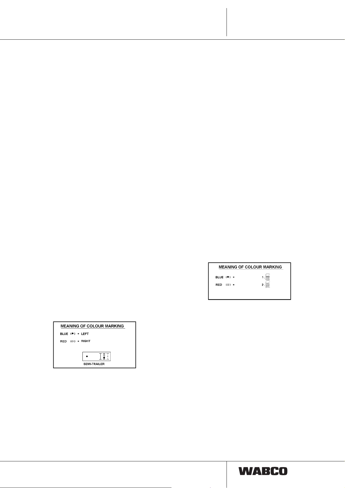
If two pressure sensors are to be installed, the red
marked cable end is to be connected to the pressure
sensor (2
The blue marked cable end is to be connected to the
pressure sensor (1
axle.
nd
PS) to the right resp. to the front axle.
st
PS) to the left resp. to the rear
Valves 1-/2-point-control, lift axle valve
Levelling valves for semitrailers with 1- or 2- point
control (right/left), for drawbar trailers 2 point control
(front/rear). Lift axle valve(s) for one or two separately
controlled lift axle(s).
The plug marked blue leads to the lift/lower valve. The
plug marked red to the 1st lift axle valve.
14

Cable overview
4.1 The TCE plug in system with
connection cable and the
Pin assignment
Cables are supplied in different lengths. In the
following the different cable types and lengths are listed
and in column ”remark“ among others the components
to be connected. (Outline drawing see appendix).
4.1.1 Overview on terminals and the
respective cables:
Terminal X11:
Brake lining wear indicator
TCE-Electronic
TCE-Elektronik
X 11
X12 X 22 X 32 X 42 X 52 X 62
X 21 X 31 X 41 X 51 X 61
TCE
4
X 13 X 23 X 33 X 43 X 53 X 63
X 14 X 24 X 34 X 44 X 54 X 64
449 874 ...0
Used
Cable
449 874 010 0
L = 1 m
Plug
R1-2 / L1-2
R-1 „A“ +5 V 1 Brake lining
R-1 „C“ Ground 2 + 5 V
L-1 „A“ + 5 V 3 Ground
L-1 „C“ Ground 4 Brake Lining
see:
Drawing
449 874 000 0 Limit value indicator,
Assignment Plug
Remark
one axle 2x1
for PAN 17: 12480038
for PAN 19-1:
12480036 **)
Assign-
A
ment
wear R
wear L
Distributor not measurable, since with W network
**) Knorr brake to BPW axle 32480057
15

4
449 884 ... 0
TCE
Cable overview
Used
Cable
449 884 023 0
L
= 1 m
1
L
= 0.4 m
2
see:
Drawing
449 884 000 0 Limit value indicator,
Remark
two axles 2x2
for PAN 17: 12480038
for PAN 19-1:
12480036 **)
449 894 ... 0
Plug
R1-2 / L1-2
R-2 „A“ + 5 V 1 Brake lin. w. R1
R-2 „C“ Ground 5 Brake lin. w. R2
R-1 „A“ + 5 V 2 + 5 V
R-1 „C“ Ground 3 Ground
L-1 „C“ Ground 3 Ground
L-1 „A“ + 5 V 2 + 5 V
L-2 „C“ Ground 4 Brake lin. w. L1
L-2 „A“ + 5 V 8 Brake lin. w. L2
Distributor not measurable, since with W network
Used
Cable
449 894 023 0
L
= 1 m
1
L
= 0.4 m
2
449 894 043 0
L
= 1 m
1
L
= 1 m
2
Assignment PlugAAssignment
see:
Drawing
449 894 000 0 Limit value indicator,
Remark
three axles 2x3
for PAN 17: 12480038
for PAN 19-1:
12480036 **)
16
Plug
R1-3 / L1-3
R-3 „A“ + 5 V 1 Brake lin. w. R1
R-3 „C“ Ground 5 Brake lin. w. R2
R-2 „A“ + 5 V 6 Brake lin. w. R3
R-2 „C“ Ground 2 + 5 V
R-1 „A“ + 5 V 3 Ground
R-1 „C“ Ground
L-1 „A“ + 5 V
L-1 „C“ Ground 3 Ground
L-2 „A“ + 5 V 2 + 5 V
L-2 „C“ Ground 4 Brake lin. w. L1
L-3 „A“ + 5 V 8 Brake lin. w. L2
L-3 „C“ Ground 7 Brake lin. w. L3
Distributor not measurable, since with W network
Assignment PlugAAssignment

Terminal X12: Supply cable
TCE-Electronic
TCE-Elektronik
X 11
X12 X 22 X 32 X 42 X 52 X 62
X 13 X 23 X 33 X 43 X 53 X 63
X 14 X 24 X 34 X 44 X 54 X 64
X 21 X 31 X 41 X 51 X 61
449 172 ... 0
Cable overview
Used
Cable
449 172 090 0
L = 9 m
449 172 100 0
L = 10 m
449 172 120 0
L = 12 m
449 172 130 0
L = 13 m
449 172 150 0
L = 15 m
TCE
see:
Drawing
449 172 000 0 ABS/EBS
Remark
Power supply
cable
ISO 7638 (7-pin)
from
semi trailer
to motor vehicle
4
Plug A Plug B
449 272 ... 0
449 133 ... 0
Plug
A
17 red Pin 30
26black Pin 15
34yellow Ground 15
45brown Ground 30
53white Warning light
62white/green CAN H
71white/brown CAN L
Used
Cable
449 272 090 0
L = 9 m
Plug
B
see:
Drawing
449 272 000 0 ABS/EBS
Colour Assignment
Remark
Supply cable to
ISO 7638
(7-pin) from
drawbar trailer
to motor vehicle
Plug A Plug B
Used
Cable
449 133 120 0
L = 12 m
see:
Drawing
449 133 000 0 ABS/EBS
Remark
Power supply
cable with
bayonet connection
17

4
449 135 ... 0
TCE
Cable overview
Plug A Plug B
449 333 ... 0
Plug A Plug B
Used
Cable
449 135 005 0
L = 0,5 m
Plug
A
17 red Pin 30
26black Pin 15
34yellow Ground 15
45brown Ground 30
53white Warning light
62white/green CAN H
71white/brown CAN L
Used
Cable
449 333 003 0
L = 0,3 m
see:
Drawing
449 135 000 0 Power supply cable
Plug
B
see:
Drawing
449 333 000 0 Power supply cable
Remark
for semitrailer with
bayonet terminal
Colour Assignment
Remark
for semitrailer /
drawbar trailer
with bayonet
counterpart to
449 133 ... 0
449 335 ... 0
Plug A Plug B
Plug
A
11white/brown CAN L
22white/green CAN H
33white Warning light
44yellow Ground 15
55brown Ground 30
66black Pin 15
77 red Pin 30
Used
Cable
449 335 110 0
L = 11 m
449 335 140 0
L = 14 m
Plug
B
see:
Drawing
449 335 000 0 Power supply cable
Colour Assignment
Remark
for semitrailer
with bayonet
counterpart to
449 135 ... 0
18

Terminal X13: Supply
TCE-Electronic
TCE-Elektronik
X 11 X 21 X 31 X 41 X 51 X 61
X12 X 22 X 32 X 42 X 52 X 62
X 13 X 23 X 33 X 43 X 53 X 63
X 14
X 24 X 34 X 44 X 54 X 64
449 113 ... 0
Cable overview
Used
Cable
449 113 100 0
L = 10 m
449 113 120 0
L = 12 m
449 113 140 0
L = 14 m
TCE
see:
Drawing
449 113 000 0 Power supply cable
Remark
Adapter from 15 pin
to 2 x 7 pin (24 N/S)
may be used
4
Plug B Plug A
Plug
A
1 8 pink Backing light
2 3 blue Rear fog light
3 9 orange Supply Ub
4 4 white/red Ground (GND 3)
5 white Ground (GND 2)
6 15 white/brown CAN_Low
7 14 white/green CAN_High
8 10 grey Brake lining wear
9 12 white/blue Lifting Axle
10 11 white/black Pressure sensor
11 5 black Back light left
12 6 brown Back light right
13 7 red Brake light
14 2 green Turn signal right
15 1 yellow Turn signal left
Plug
B
Colour Assignment
(pin 30-2)
449 121 ... 0
Used
Cable
449 121 120 0
L = 12 m
see:
Drawing
449 121 000 0 Power supply
Remark
cable
for Aspöck
2 x 7 pin to 15 pin
Terminal
19

4
449 123 ... 0
TCE
Cable overview
449 311 ... 0
Plug B
Plug A
Used
Cable
449 123 120 0
L = 12 m
Used
Cable
449 311 120 0
L = 12 m
Plug assignment see page 19
see:
Drawing
449 123 000 0 Power supply
see:
Drawing
449 311 000 0 Power supply
Remark
cable
for
drawbar trailer
Remark
cable
for Hella
Plug adapter
20
2

Terminal X14: Diagnosis
TCE-Electronic
TCE-Elektronik
X 11 X 21 X 31 X 41 X 51 X 61
X12
X 22 X 32 X 42 X 52 X 62
Cable overview
TCE
4
X 13 X 23 X 33 X 43 X 53 X 63
X 14
449 672 ... 0
Plug B
449 644 ... 0
X 24 X 34 X 44 X 54 X 64
Plug A
Plug A
Used
Cable
449 672 030 0
see:
Drawing
449 672 000 0 Diagnostic cable
L = 3 m
449 672 040 0
L = 4 m
449 672 060 0
L = 6 m
449 672 080 0
L = 8 m
449 672 090 0
L = 9 m
Plug
A
Plug
B
14 K wire
21 Supply
37 Ground
Used
Cable
449 644 196 0
L
= 10 m
1
L
= 4 m
2
see:
Drawing
449 644 000 0 Y diagnostic cable
Remark
with terminal
for connection cable
446 300 329 2
( 6 m long ) to
Diagnostic Interface
Set 446 301 021 0
Assignment
Remark
with terminal
for connection cable
446 300 329 2
( 6 m long ) to
Diagnostic Interface
Set 446 301 021 0
and warning light
cable with green
warning light:
446 105 521 2 (cable
with plug
441 032 312 2)
Plug B
Plug
A
Plug
B
Assignment
4 Ground
8 warning light
14 K wire
21 Supply
37 Ground
2
21

4
TCE
Cable overview
Terminal X21: I/O Typ, Erweiterung
TCE-Elektronik
TCE-Electronic
X 11
X12
X 21
X 22
X 31 X 41 X 51 X 61
X 32 X 42 X 52 X 62
X 13
X 14
449 902 ... 0
X 23
X 24
X 33 X 43 X 53 X 63
X 34 X 44 X 54 X 64
Plug A
Used
Cable
449 902 050 0
L = 5 m
see:
Remark
Drawing
449 902 000 0 RGE
special functions
449 902 070 0
L = 7 m
Plug
Colour Assignment
A
1 white/green Supply 2
2 purple Digital inlet 2
3 yellow Digital inlet 1
4 green Supply 1
5 brown Ground
6 black Digital inlet 4
7 white Digital inlet 3
8 white/brown Ground
449 903 ... 0
Plug B Plug A
Used
Cable
449 903 050 0
see:
Drawing
449 903 000 0 for ECAS control box
L = 5 m
449 903 090 0
L = 9 m
Plug
A
Plug
B
24 Inlet 2
33 Inlet 1
41 Supply
52 Ground
75 Inlet 3
Remark
446 156 000 0
Assignment
22

Terminal X22: Cable to Trailer EBS
TCE-Elektronik
TCE-Electronic
X 11
X12
X 31 X 41 X 51 X 61
X 21
X 32 X 42 X 52 X 62
X 22
Cable overview
TCE
4
X 13
X 14
449 399 ... 0
Plug B Plug A
449 394 ... 0
Plug B
X 33 X 43 X 53 X 63
X 23
X 34 X 44 X 54 X 64
X 24
Plug A
Used
Cable
449 399 020 0
see:
Drawing
449 399 000 0 to EBS trailer
L = 2 m
Plug
A
Plug
B
15 Ground
27 Supply
51 CAN L
82 CAN H
Used
Cable
449 394 346 0
L
= 2 m
1
L
= 15 m
2
see:
Drawing
449 394 000 0 to EBS trailer
449 394 366 0
L
= 2 m
1
L
= 18 m
2
449 394 386 0
L
= 2 m
1
L
= 20 m
2
Remark
modulator
480 102 002 0
Assignment
Remark
modulator
480 102 002 0
and RGE with CAN
(telematic)
Plug
A
Plug
B
Colour Assignment
15 Ground
27 Supply
51 CAN L
62 CAN H
3
4 red Supply
7 blue CAN L
open
brown Ground
8 yellow CAN H
23
 Loading...