


Tianjin FAW |
|
|
|
|
|
CA4GA5 Engine Maintenance Manual |
|
|
Contents |
|
|
Chapter 1 Technical Parameters and Maintenance Preparation Data of Engine ...................... |
2 |
||
Section 1 |
Technical Parameters of Engine ...................................................................... |
|
3 |
Section 2 |
Maintenance Preparation ................................................................................. |
|
5 |
Section 3 |
General Maintenance Parameters .................................................................... |
|
8 |
Section 4 Engine Maintenance ...................................................................................... |
|
14 |
|
Chapter 2 Engine Structure ........................................................................................................... |
|
16 |
|
Section 1 |
Cylinder block, cylinder head and crank connecting rod mechanism ........... |
17 |
|
Section 2 Valve actuating mechanism ........................................................................... |
|
24 |
|
Section 3 |
Lubrication System........................................................................................ |
|
29 |
Section 4 Cooling System.............................................................................................. |
|
33 |
|
Section 5 |
Intake and Exhaust Systems .......................................................................... |
|
35 |
Section 6 Fuel System ................................................................................................... |
|
38 |
|
Section 7 |
Ignition System .............................................................................................. |
|
40 |
Section 8 |
Other sensors and other actuating mechanism............................................... |
42 |
|
Chapter 3 Engine Adjustment and Maintenance......................................................................... |
|
44 |
|
Section 1 Engine Adjustment ........................................................................................ |
|
45 |
|
Section 2 |
Engine Maintenance When Engine is Installed on the Vehicle..................... |
49 |
|
Section 3 Engine Adjustment and Maintenance ............................................................ |
|
62 |
|
1

Tianjin FAW
CA4GA5 Engine Maintenance Manual
|
Chapter 1 |
|
|
Technical Parameters and Maintenance |
|
|
Preparation Data of Engine |
|
Section 1 |
Technical Parameters of Engine ............................................................................................................... |
3 |
Section 2 |
Maintenance Preparation .......................................................................................................................... |
5 |
Section 3 |
General Maintenance Parameters ............................................................................................................. |
8 |
Section 4 |
Engine Maintenance ............................................................................................................................... |
14 |
2

Tianjin FAW
CA4GA5 Engine Maintenance Manual
Section 1 Technical Parameters of Engine
Engine model: CA4GA5
Displacement: 1.497 L
Bore ×stroke: 73×89.4 mm
Compression ratio: 10.2: 1,
Rated power/rotating speed: 75kW/6000r/min
Maximum net torque/rotating speed: 135N.m/4400r/min
Fuel specification: octane number above 93# unleaded gasoline or 93# ethanol gasoline and above. Engine dimension (L*W*H): 421*554*637 (mm)
Note: The length refers to the distance from rear end of cylinder block to front end of crank pulley;
The width refers to the distance from the outermost end of left side to that of right side when the engine is in upright state.
The height refers to the distance from the highest point to the lowest point of the engine when the engine is in upright state.
Net weight of engine (cooling compressor power steering pump and combination bracket are excluded): 104Kg Valve timing
Intake valve opening: 38°before TDC~12°after TDC.
Intake valve closing: 22°~72°after BDC.
Exhaust valve opening: 48.5°before BDC.
Exhaust valve closing: 5.5°after TDC
Lubrication system volume
Total volume of lubrication system: 4.0L.
High level oil volume of engine oil pan: 3.5L.
Low level oil volume of engine oil pan: 2.5L
Cooling system:
Use the coolant containing water (at 20 , PH is 6.5-8.5) and ethylene glycol. Pure water is not allowed. Coolant volume percentage
Ethylene glycol content |
Corresponding water content |
Protection temperature |
|
|
|
Min. 35% |
65% |
-20 |
|
|
|
40% |
60% |
-24 |
|
|
|
Max. 45% |
55% |
-31 |
|
|
|
The maximum allowed temperature of engine coolant: 110 .
Coolant alarm temperature: 115 .
3

|
|
Tianjin FAW |
|
|
|
CA4GA5 Engine Maintenance Manual |
|
|
|
|
|
|
|
|
|
||
|
|
|
|
|
|
|
||
|
|
|
|
|
|
|
|
|
|
Temperature regulation range of thermosistor: |
|
|
|
|
|||
|
Opening temperature: (82±2) ; full-open temperature: 95 . |
|
|
|
||||
|
Maximum lift of the thermosistor: ≥8mm. |
|
|
|
|
|||
|
Alternator: |
|
|
|
|
|||
|
Generator type: integrated alternator. |
|
|
|
|
|||
|
Voltage (V): 13.5±0.1. |
|
|
|
|
|||
|
Output current (refer to the table): |
|
|
|
|
|||
|
|
|
|
Generator output current |
|
|
|
|
|
|
|
|
|
|
|
|
|
|
|
Output current (A) |
|
|
Engine speed (r/min) |
|
||
|
|
|
|
|
|
|
|
|
|
|
Cold state |
|
Hot state |
|
|
||
|
|
|
|
|
|
|||
|
|
|
|
|
|
|
|
|
|
|
≥35 |
|
24~27 |
|
1800 |
|
|
|
|
|
|
|
|
|
|
|
|
|
≥45 |
|
31~34 |
|
2000 |
|
|
|
|
|
|
|
|
|
|
|
|
|
≥77 |
|
≥65 |
|
6000 |
|
|
|
|
|
|
|
|
|
||
|
Engine speed: 1000~18000(r/min). |
|
|
|
|
|||
Operating temperature of the generator: -40 ~105 .
Generator weight: 4.1kg.
Note:
Cold state: the state when the generator starts to work.
Hot state: the state after the generator works for 30 minutes.
Multi-wedge belt (belt pulley slot type): 6PK
Starter
Electromagnetic operation forced engagement.
Rated voltage: 12V;
Nominal power: 1.1kW (20 ).
Operating temperature of the starter: -40 ~120 .
Emission control standard: National III and IV
4

Tianjin FAW
CA4GA5 Engine Maintenance Manual
Section 2 Maintenance Preparation
1.Maintenance Notes (refer to CA4GA1 Engine Maintenance Manual)
2.Maintenance preparation notes
(1) Mechanical part of the engine
Special maintenance tools
No. |
Description |
Location |
||
|
|
Main body |
|
|
|
Special fixture for installing |
Spring |
|
|
1 |
“C” bushing |
Piston rod |
||
and removing piston pin |
||||
|
“M” guide rod |
|
||
|
|
|
||
|
|
“N” guide rod |
|
|
2 |
Piston tool |
Piston |
||
3 |
Adjustment tool for spark plug |
Spark plug clearance |
||
Recommended tools |
|
|
||
|
|
|
|
|
No. |
Description |
Location |
||
1 |
Disassembling tool for valve guide pipe |
Valve guide pipe |
||
2 |
Disassembling tool for valve stem oil seal |
Valve stem oil seal |
||
3 |
Press-mounting tool for valve lock clamp |
Valve lock clamp |
||
4 |
Attachment |
|
||
|
|
|||
5 |
Cylinder head bolt wrench joint |
|
Cylinder head bolt |
|
|
|
Fixing tool for crankshaft and |
|
|
6 |
Disassembling fixture for crank |
flywheel |
Crank pulley |
|
pulley |
Disassembling bar for crank |
|||
|
|
|||
|
|
pulley |
|
|
|
|
Main body |
|
|
|
|
Spring |
|
|
7 |
Special fixture for piston pin |
“C” bushing |
Piston rod |
|
|
|
“M” guide rod |
|
|
|
|
“N” guide rod |
|
|
8 |
Disassembling tool for rear oil seal of crankshaft |
Rear oil seal of crankshaft |
||
9 |
Disassembling tool for front oil seal of crankshaft |
Front oil seal of |
||
crankshaft |
||||
|
|
|
||
10 |
Disassembling tool for engine oil filter |
Engine oil filter |
||
11 |
Valve clearance adjustment tool |
Valve tappet pressure clamp |
valve clearance |
|
kits |
Feeler gauge |
|||
|
|
|||
12 |
Fixing fixture for crank pulley |
Crank pulley |
||
13 |
Hose plug |
All hoses |
||
14 |
Fuel pressure gauge |
Fuel pressure |
||
|
|
Disassembling tool for water |
|
|
|
|
pump bearing |
|
|
|
|
Disassembling tool for water |
|
|
|
Disassembling tool for water |
pump seals |
|
|
15 |
Disassembling tool for water |
Water pump |
||
pump |
||||
|
pump rotor |
|
||
|
|
|
||
|
|
Receiving tool for water pump |
|
|
|
|
bearing |
|
|
|
|
Water pump bearing base plate |
|
|
16 |
Engine overhaul bracket |
|
Engine |
|
17 |
Engine overhaul connection bracket |
Engine |
||
18 |
Flywheel locking tool |
|
Flywheel |
|
19 |
Disassembling fixture for cylinder head |
Cylinder head |
||
5

|
|
|
|
Tianjin FAW |
|
|
|
CA4GA5 Engine Maintenance Manual |
|
|||
|
|
|
|
|
|
|
|
|
|
|
||
|
|
|
|
|
|
|
|
|
|
|
||
|
|
|
|
|
|
|
|
|
|
|
|
|
|
|
|
|
|
|
|
|
|
|
|
|
|
|
|
20 |
|
|
Engine slings |
|
|
Engine |
|
|||
|
|
21 |
|
|
Piston tool |
|
|
Piston |
|
|||
|
|
22 |
|
|
Sealant gun |
|
|
All kinds of sealant |
|
|||
|
|
23 |
|
|
Disassembling tool for clutch housing and pressure plate |
Clutch housing and |
|
|||||
|
|
|
|
pressure plate |
|
|||||||
|
|
|
|
|
|
|
|
|
|
|
|
|
|
|
24 |
|
|
Stainless steel wire wiper |
|
|
Remove sealant and |
|
|||
|
|
25 |
|
|
Scraper knife |
|
|
carbon deposit etc. |
|
|||
|
|
26 |
|
|
Disassembling tool for engine oil pan |
|
Engine oil, rear oil seal |
|
||||
|
|
|
|
|
seat assembly etc. |
|
||||||
|
|
|
|
|
|
|
|
|
|
|
|
|
|
|
27 |
|
|
Screwdriver (flat head screwdriver, Phillips screwdriver) |
|
|
|||||
|
|
28 |
|
|
spark plug wrench |
|
|
Spark plug |
|
|||
|
|
29 |
|
|
Radiator cover tester |
|
|
Radiator cover |
|
|||
|
|
30 |
|
|
Measuring tool for cylinder bore |
|
|
Cylinder bore |
|
|||
|
|
31 |
|
|
Chamfering reamer for cylinder hole |
|
Cylinder hole |
|
||||
|
|
32 |
|
|
All kinds of casing heads |
|
|
Bolt and nut |
|
|||
|
Equipments |
|
|
|
|
|
|
|
||||
|
|
|
|
|
|
|
|
|
|
|
||
|
|
No. |
|
|
|
|
Description |
|
|
|||
|
|
1 |
|
|
Straightening tool for connecting rod |
|
|
|
||||
|
|
2 |
|
|
Expanding tool for piston ring |
|
|
|
|
|||
|
|
3 |
|
|
Compressing tool for piston ring |
|
|
|
|
|||
|
Special sealant |
|
|
|
|
|
|
|
||||
|
|
|
|
|
|
|
|
|
|
|
|
|
|
No. |
|
|
|
|
Location |
|
Sealant type |
|
Remark |
|
|
|
1 |
|
Stud – install engine front support |
|
TB1322 |
Apply the sealant on the end connecting |
|
|||||
|
|
bracket |
|
|
|
with cylinder head |
|
|||||
|
|
|
|
|
|
|
|
|||||
|
2 |
|
Cylinder block sand outlet hole bowl- |
|
TB1386D |
Apply the sealant on the edge of the plug |
|
|||||
|
|
type plug |
|
|
|
|
||||||
|
|
|
|
|
|
|
|
|
|
|||
|
3 |
|
Cylinder block main oil channel bowl- |
|
TB1386D |
Apply the sealant on the edge of the plug |
|
|||||
|
|
type plug |
|
|
|
|
||||||
|
|
|
|
|
|
|
|
|
|
|||
|
4 |
|
Hexagon head tapered screw plug-at |
|
TB1110B |
Apply the sealant on plug screw thread |
|
|||||
|
|
drainage hole of cylinder block |
|
|
||||||||
|
|
|
|
|
|
|
|
|||||
|
5 |
|
Cylinder head sand outlet hole bowl- |
|
TB1386D |
Apply the sealant on the edge of the plug |
|
|||||
|
|
type plug |
|
|
|
|
||||||
|
|
|
|
|
|
|
|
|
|
|||
|
6 |
|
Rear oil seal seat assembly for |
|
TB1280E |
Apply the sealant on rear oil seal seat |
|
|||||
|
|
crankshaft |
|
|
|
surface of crankshaft |
|
|||||
|
|
|
|
|
|
|
|
|||||
|
7 |
|
Stud - intake manifold |
|
TB1322 |
Apply the sealant on the end connecting |
|
|||||
|
|
|
with cylinder head |
|
||||||||
|
|
|
|
|
|
|
|
|
|
|
||
|
8 |
|
Stud – exhaust manifold |
|
TB1322 |
Apply the sealant on the end connecting |
|
|||||
|
|
|
with cylinder head |
|
||||||||
|
|
|
|
|
|
|
|
|
|
|
||
|
|
|
|
|
|
|
|
|
|
Apply the sealant on the bottom of cylinder |
|
|
|
9 |
|
Engine oil pan assembly |
|
TB1280E |
block, applied diameter is determined by |
|
|||||
|
|
|
|
|
|
|
|
|
|
testing |
|
|
|
10 |
|
Joint surface of engine oil dipstick pipe |
|
TB1280E |
Apply the sealant on the head of engine oil |
|
|||||
|
|
and cylinder block location hole |
|
gauge pipe |
|
|
||||||
|
|
|
|
|
|
|
||||||
|
11 |
|
Joint – engine oil filter |
|
TB1110B |
Apply the sealant on the end connecting |
|
|||||
|
|
|
engine oil filter |
|
|
|||||||
|
|
|
|
|
|
|
|
|
|
|
|
|
|
12 |
|
Stud - install idler assembly |
|
TB1322 |
Apply the sealant on the end connecting |
|
|||||
|
|
|
with cylinder head |
|
||||||||
|
|
|
|
|
|
|
|
|
|
|
||
|
13 |
|
Chain chamber cover assembly |
|
TB1280E |
Apply the sealant on chain chamber cover |
|
|||||
|
|
|
surface |
|
|
|||||||
|
|
|
|
|
|
|
|
|
|
|
|
|
|
14 |
|
Engine water inlet pipe seat assembly |
|
TB1280E |
Apply the sealant on engine water inlet pipe |
|
|||||
|
|
|
seat surface |
|
|
|||||||
|
|
|
|
|
|
|
|
|
|
|
|
|
|
15 |
|
Engine water outlet pipe |
|
TB1280E |
Apply the sealant on engine outlet pipe |
|
|||||
|
|
|
surface |
|
|
|||||||
|
|
|
|
|
|
|
|
|
|
|
|
|
|
16 |
|
Studinstall engine water inlet pipe seat |
|
TB1110B |
Apply the sealant on threads |
|
|||||
6

|
|
|
|
Tianjin FAW |
|
|
CA4GA5 Engine Maintenance Manual |
|
|
|
|
|
|
|
|
|
|
|
|
|
|
|
|
|
|
|
|
|
|
|
|
|
|
|
|
|
|
|
|
|
|
|
||
|
|
|
assembly |
|
|
|
||
|
17 |
|
Coolant temperature sensor assembly |
TB1110B |
Apply the sealant on threads |
|
||
|
18 |
|
Engine oil pressure alarm assembly |
TB1110B |
Apply the sealant on threads |
|
||
|
19 |
|
Relief valve assembly |
TB1110B |
Apply the sealant on threads |
|
||
|
20 |
|
Studchain tensioner assembly |
TB1322 |
Apply the sealant on threads |
|
||
|
21 |
|
Chain lubrication nozzle |
TB1110B |
Apply the sealant on threads |
|
||
|
22 |
|
Cylinder gasket assembly |
TB1280E |
Apply the sealant on cylinder block front |
|
||
|
|
end top surface edge |
|
|||||
|
|
|
|
|
|
|
|
|
|
23 |
|
Drain plug assembly |
TB1280E |
Apply the sealant on drain plug assembly |
|
||
|
|
thread. |
|
|||||
|
|
|
|
|
|
|
|
|
|
(Note) |
1. Sealant manufacturer recommends using products Three Bond Chemical Industry Co., Ltd.. |
|
|||||
2.When applying sealant on the threads, do not apply it on the first two threads.
3.When applying sealant on sealed oil channel and water channel, do not squeeze sealants into water channel or oil channel to prevent them from being blocked.
Comparison of CA4GA5 and CA4GA1 Engine Changing Parts
No. |
Part description |
Changing point |
Remark |
|
1 |
Cylinder block |
1. Height increase |
|
|
|
|
1. Crank arm lengthened |
Crankshaft diameter |
|
2 |
Crankshaft |
2. Connecting rod shaft diameter |
||
unchanged |
||||
|
|
enlarged |
||
|
|
|
||
3 |
Piston |
Top pit enlarged |
|
|
4 |
Connecting rod |
Big end hole enlarged |
|
|
5 |
Upper bearing shell for |
Connecting rod shaft diameter |
|
|
connecting rod |
enlarged |
|
||
|
|
|||
6 |
Lower bearing shell for |
Connecting rod shaft diameter |
|
|
connecting rod |
enlarged |
|
||
|
|
|||
|
|
1. Intake valve seat |
|
|
7 |
Cylinder head assembly |
2. Exhaust valve seat |
|
|
|
|
3. Lift changing |
|
|
8 |
Spark plug |
Heat value changing |
Model and clearance |
|
changing |
||||
|
|
|
||
9 |
Intake valve |
Dimension enlarged |
|
|
10 |
Exhaust valve |
Dimension enlarged |
|
|
11 |
Intake camshaft assembly |
Lift changing |
|
|
12 |
Exhaust camshaft assembly |
Lift changing |
|
|
13 |
Chain guide rail assembly |
Length changing |
Engine block heightened |
|
14 |
Chain tension arm assembly |
Length changing |
Engine block heightened |
|
15 |
Timing chain |
Number of teeth increasing |
Engine block heightened |
|
16 |
Chain tooth cover assembly |
Enlarging |
Engine block heightened |
|
17 |
Engine oil dipstick assembly |
Lengthening |
Engine block heightened |
|
18 |
Engine oil dipstick pipe |
Lengthening |
Engine block heightened |
|
assembly |
||||
|
|
|
||
19 |
Intake manifold assembly |
Change to central updraught type |
|
|
20 |
Hexagon flange nut |
|
Install intake manifold |
|
21 |
Intake manifold bracket |
Lengthening |
Engine block heightened |
|
22 |
Exhaust manifold assembly |
Appearance changing |
|
|
23 |
Canister solenoid valve exhaust |
Lengthening |
Position change |
|
pipe |
||||
|
|
|
||
24 |
Electronic throttle valve water |
Lengthening |
Position change |
|
inlet/outlet pipe |
||||
|
|
|
(2) Electronic control fuel injection
Refer to CA4GA1 Engine Maintenance Manual (electronic control)
7

Tianjin FAW
CA4GA5 Engine Maintenance Manual
Section 3 General Maintenance Parameters
1. Mechanical Part
(1) Maintenance Data
Cylinder head |
Joint surface deformation |
|
|
|
Cylinder block side |
Specified value |
0.05 |
|
|
Allowed limit |
0.10 |
|
Maximum repairing and fitting quantity |
|
0.16 |
|
Intake/exhaust manifold side |
Specified value |
0.08 |
|
|
Allowed limit |
0.16 |
|
Valve seat opening label and width |
|
|
|
|
Intake side |
1.3±0.2 |
|
|
Exhaust side |
1.25±0.2 |
|
Valve seat opening contact angle |
|
45°±30′ |
|
Allowed lower limit of valve seat opening |
Intake side |
0.49 |
|
|
Exhaust side |
0.46 |
|
1st camshaft bearing support |
|
φ32(+0.055, +0.030) |
|
|
Intake |
φ26(+0.021,0) |
|
|
Exhaust |
φ23(+0.021,0) |
|
2nd ~5th camshaft bearing support hole standard value |
|
|
|
Fuel spray nozzle hole diameter |
|
|
|
|
Standard |
φ12 |
|
|
Limit |
φ12.5 |
|
|
|
|
1st camshaft bearing cover |
Intake side |
Locating slot width |
3(+0.05,0) |
|
Exhaust side |
Bearing cap width |
21(+0.05,0) |
|
|
|
|
Valve guide pipe |
Valve guide pipe diameter |
|
|
|
Intake valve |
|
φ5(+0.022,+0.010) |
|
Exhaust valve |
|
φ5(+0.022,+0.010) |
|
Protruding height of valve guide pipe |
|
15.1±0.2 |
|
|
|
|
Valve |
Conical surface angle |
|
45°30′ |
|
Valve stem outer diameter |
|
|
|
Intake valve |
Specified value |
φ5(-0.010,-0.028) |
|
|
Limit |
φ4.962 |
|
Exhaust valve |
Specified value |
φ5(-0.020,-0.038) |
|
|
|
|
8

|
|
Tianjin FAW |
|
CA4GA5 Engine Maintenance Manual |
|
||
|
|
|
|
|
|
||
|
|
|
|
|
|
||
|
|
|
|
|
|
|
|
|
|
|
|
|
|
|
|
|
|
|
|
|
Limit |
φ4.952 |
|
|
|
|
Valve clearance |
|
|
|
|
|
|
|
Standard |
Intake |
0.02~0.05 |
|
|
|
|
|
|
|
Exhaust |
0.03~0.06 |
|
|
|
|
Limit |
Intake |
0.07 |
|
|
|
|
|
|
|
Exhaust |
0.09 |
|
|
|
|
Edge thickness |
|
|
|
|
|
|
|
Standard |
Intake |
1.40 |
|
|
|
|
|
|
|
Exhaust |
1.45 |
|
|
|
|
Limit |
Intake |
0.9 |
|
|
|
|
|
|
|
Exhaust |
0.9 |
|
|
|
|
|
|
|
||
|
Intake camshaft |
Shaft diameter standard value |
1st camshaft diameter |
φ32(0,-0.016) |
|
||
|
|
|
|
|
2nd ~ 5th camshaft diameter |
φ23(-0.035,-0.051) |
|
|
|
|
Cam height |
Standard value |
41.2 |
|
|
|
|
|
|
|
Limit value |
40.95 |
|
|
|
|
1st shaft diameter oil clearance |
Standard value |
0.03~0.071 |
|
|
|
|
|
|
|
Limit value |
0.10 |
|
|
|
|
5th shaft diameter oil clearance |
Standard value |
0.035~0.072 |
|
|
|
|
|
|
|
Limit value |
0.11 |
|
|
|
|
Radial runout |
Standard value |
0.03 |
|
|
|
|
|
|
|
Limit value |
0.04 |
|
|
|
|
|
|
|
||
|
Exhaust camshaft |
Shaft diameter standard value |
1st camshaft diameter |
φ26(-0.035,-0.051) |
|
||
|
|
|
|
|
2nd ~ 5th camshaft diameter |
φ23(-0.035,-0.051) |
|
|
|
|
Cam height |
Standard value |
41.1 |
|
|
|
|
|
|
|
Limit value |
40.04 |
|
|
|
|
Shaft diameter oil clearance |
Standard value |
0.035~0.072 |
|
|
|
|
|
|
|
Limit value |
0.11 |
|
|
|
|
Radial runout |
Standard value |
0.03 |
|
|
|
|
|
|
|
Limit value |
0.04 |
|
|
|
|
|
|
|
||
|
Cylinder block |
Top surface deformed |
|
|
|
||
|
|
|
|
|
Standard value |
0.05 |
|
|
|
|
|
|
Maximum value |
0.10 |
|
|
|
|
Cylinder bore diameter (standard) |
|
|
|
|
|
|
|
|
|
Grade A |
φ73~φ73.01 |
|
|
|
|
|
|
Grade B |
φ73.01~φ73.02 |
|
|
|
|
|
|
Grade C |
φ73.02~φ73.03 |
|
|
|
|
|
|
|
|
|
9

|
|
Tianjin FAW |
|
|
CA4GA5 Engine Maintenance Manual |
|
||
|
|
|
|
|
|
|
||
|
|
|
|
|
|
|
||
|
|
|
|
|
|
|
|
|
|
|
|
|
|
|
|
|
|
|
|
|
|
|
|
Wear limit |
0.08 |
|
|
|
|
|
|
|
Enlarging 0.25mm type |
φ73.25~φ73.28 |
|
|
|
|
|
|
|
Enlarging 0.50mm type |
φ73.50~φ73.53 |
|
|
|
|
Engine oil pump hole diameter |
|
|
|
||
|
|
|
|
|
|
Standard |
φ55.1(+0.06, +0.03) |
|
|
|
|
|
|
|
Limit |
φ55.3 |
|
|
|
|
|
|
|
|
||
|
Piston |
Piston diameter |
Standard |
Grade A |
φ72.97~φ72.98 |
|
||
|
|
|
|
|
|
Grade B |
φ72.98~φ72.99 |
|
|
|
|
|
|
|
Grade C |
φ72.99~φ73.00 |
|
|
|
|
|
|
Wear limit |
|
|
|
|
|
|
|
|
|
Enlarging 0.25mm type |
φ73.25 |
|
|
|
|
|
|
|
Enlarging 0.50mm type |
φ73.50 |
|
|
|
|
Piston oil clearance |
|
|
|
|
|
|
|
|
|
|
|
Standard value |
0.02~0.04 |
|
|
|
|
|
|
|
Limit value |
0. 06 |
|
|
|
|
Piston top pit diameter |
|
|
φ60.4 |
|
|
|
|
|
|
|
|
|
||
|
Piston ring |
Piston ring thickness |
|
1st compression ring |
Less than 1.2 |
|
||
|
|
|
|
|
|
2nd compression ring |
Less than 1.2 |
|
|
|
|
|
|
|
Oil ring |
Less than 2.0 |
|
|
|
|
Piston ring opening clearance (Standard) |
|
|
|||
|
|
|
|
|
|
1st compression ring |
0.20~0.30 |
|
|
|
|
|
|
|
2nd compression ring |
0.40~0.55 |
|
|
|
|
|
|
|
Oil ring |
0.20~0.70 |
|
|
|
|
Limit value |
|
1st compression ring |
0.5 |
|
|
|
|
|
|
|
|
2nd compression ring |
0.7 |
|
|
|
|
|
|
|
Oil ring |
1.0 |
|
|
|
|
Piston ring groove clearance(Standard) |
|
|
|
||
|
|
|
|
|
|
1st compression ring |
0.04~0.09 |
|
|
|
|
|
|
|
2nd compression ring |
0.02~0.06 |
|
|
|
|
Limit value |
|
1st compression ring |
0.13 |
|
|
|
|
|
|
|
|
2nd compression ring |
0.08 |
|
|
|
|
|
|
|
|||
|
Piston pin |
Piston pin |
Clearance between outer ring and piston |
φ18(+0.034, +0.028) |
|
|||
|
|
|
|
|
|
Standard |
0.005~0.011 |
|
|
|
|
|
|
|
Limit |
0.016 |
|
|
|
|
Interference fit with connecting rod |
|
0.017~0.034 |
|
||
|
|
|
|
|
|
|
||
|
Connecting rod |
Bent and deformed |
|
Limit |
0.03 |
|
||
|
|
|
|
|
|
|
|
|
10
|
|
Tianjin FAW |
|
CA4GA5 Engine Maintenance Manual |
|
||
|
|
|
|
|
|
||
|
|
|
|
|
|
||
|
|
|
|
|
|
|
|
|
|
|
|
|
|
|
|
|
|
|
Bent and deformed |
Limit |
0.03 |
|
|
|
|
|
Connecting rod big end clearance |
Standard |
0.017~0.029 |
|
|
|
|
|
|
|
Limit |
0.046 |
|
|
|
|
Connecting rod axial clearance |
Standard |
0.20~0.40 |
|
|
|
|
|
|
|
Limit |
0.50 |
|
|
|
|
|
|
|
||
|
Crankshaft |
Main shaft diameter |
|
|
|
||
|
|
|
|
|
Standard |
φ46(0,-0.018) |
|
|
|
|
|
|
Enlarging 0.25mm type |
φ45.75~φ45.57 |
|
|
|
|
|
|
Enlarging 0.50mm type |
φ45.5~φ45.32 |
|
|
|
|
Main shaft diameter clearance |
|
|
|
|
|
|
|
|
|
Standard |
0.025~0.043 |
|
|
|
|
|
|
Limit |
0.068 |
|
|
|
|
Connecting rod shaft diameter clearance |
|
|
||
|
|
|
|
|
Standard |
0.017~0.035 |
|
|
|
|
|
|
Limit |
0.052 |
|
|
|
|
Crank pin diameter |
|
|
|
|
|
|
|
|
|
Standard |
φ44(0,-0.018) |
|
|
|
|
|
|
Enlarging 0.25mm type |
φ39.75~φ39.57 |
|
|
|
|
|
|
Enlarging 0.50mm type |
φ39.50~φ39.32 |
|
|
|
|
|
|
|
||
|
Intake manifold |
Seal groove depth |
|
4±0.1mm |
|
||
|
|
|
Seal ring protruding height |
Standard |
2±0.1mm |
|
|
|
|
|
|
|
Limit |
1.8mm |
|
|
|
|
|
|
|
||
|
Exhaust manifold |
Flange deformation |
|
|
|
||
|
|
|
|
|
Standard |
0.25 |
|
|
|
|
|
|
Limit |
0.40 |
|
|
|
|
|
|
|
||
|
Valve clearance |
Cold state |
intake valve |
0.2±0.03mm |
|
||
|
|
|
|
|
Exhaust valve |
0.3±0.03mm |
|
|
|
|
|
|
|
||
|
Timing chain |
Flexibility limit |
|
4mm [with 127N applied] |
|
||
|
|
|
|
|
|
||
|
Chain chamber cover |
OCV Control valve hole diameter |
Standard |
φ18(+0.018,0) |
|
||
|
|
|
|
|
Limit |
φ18.045 |
|
|
|
|
Joint surface deformation |
Standard |
0.10 |
|
|
|
|
|
|
|
Limit |
0.25 |
|
|
|
|
|
|
|
||
|
Upper and lower connecting |
Shell width |
|
14.5(0,-0.2) |
|
||
|
rod bearing shell |
Free opening width |
|
47( +1.5,+0.5) |
|
||
|
|
|
|
|
|||
|
|
|
Central thickness |
|
1.5(+0.009,-0.003) |
|
|
|
|
|
|
|
|
|
|
11

Tianjin FAW
CA4GA5 Engine Maintenance Manual
(Note) Unit: mm
(2) Tightening torque specifications
No. |
Name |
Qty. |
Spec. |
Tightening torque |
Remark |
|
(N.m) |
||||||
|
|
|
|
|
||
|
|
|
|
|
|
|
1 |
Bolt and nut for engine front support |
2+2 |
M10 |
50±10 |
|
|
|
|
|
|
|
|
|
2 |
Cylinder head bolt |
10 |
M9×1.25 |
34±3+120° |
Dipping |
|
oil |
||||||
|
|
|
|
|
||
|
|
|
|
|
|
|
3 |
Cylinder head cover bolt |
11+2 |
M6 |
11±2 |
|
|
|
|
|
|
|
|
|
4 |
Connecting rod bolt |
8 |
M8X1 |
22±2.5+90° |
Dipping |
|
oil |
||||||
|
|
|
|
|
||
|
|
|
|
|
|
|
5 |
Main bearing bolt |
10 |
M10×1.25 |
60±5 |
Dipping |
|
oil |
||||||
|
|
|
|
|
||
|
|
|
|
|
|
|
6 |
Flywheel bolt |
6 |
M10×1.25 |
78±5 |
|
|
|
|
|
|
|
|
|
7 |
Crankshaft belt pulley bolt |
1 |
M14×1.5 |
200±10 |
|
|
|
|
|
|
|
|
|
8 |
Rear oil seal seat assembly |
4 |
M6 |
8±2 |
|
|
|
|
|
|
|
|
|
9 |
Camshaft bearing cover |
20 |
M6 |
12.5±2 |
|
|
|
|
|
|
|
|
|
10 |
Stud for connecting intake and exhaust |
5+5 |
M8 |
6±1.2 |
|
|
manifold and cylinder head |
|
|||||
|
|
|
|
|
||
|
|
|
|
|
|
|
11 |
Nut for tightening intake manifold |
5 |
M8 |
19±4 |
|
|
|
|
|
|
|
|
|
12 |
Nut for tightening exhaust manifold |
5 |
M8 |
23±5 |
|
|
|
|
|
|
|
|
|
13 |
Bolt and nut for engine oil pan |
14+2 |
M6 |
8±2 |
|
|
|
|
|
|
|
|
|
14 |
Drain plug assembly |
1 |
M16×1.5 |
30±5 |
|
|
|
|
|
|
|
|
|
15 |
Engine oil pump assembly |
3 |
M6 |
9±1.8 |
|
|
|
|
|
|
|
|
|
16 |
Relief valve assembly |
1 |
M22×1.5 |
40±5 |
|
|
|
|
|
|
|
|
|
17 |
Engine oil filter joint |
1 |
M20×1.5 |
44±9 |
|
|
|
|
|
|
|
|
|
18 |
Idler assembly |
1 |
M10 |
44±9 |
|
|
|
|
|
|
|
|
|
19 |
VCT controller assembly |
1 |
M10 |
47±7 |
|
|
|
|
|
|
|
|
|
20 |
OCV control valve assembly |
1 |
M6 |
8±2 |
|
|
|
|
|
|
|
|
|
21 |
OCV control valve filter bolt |
1 |
M14×1.5 |
24.5±5 |
|
|
|
|
|
|
|
|
|
22 |
Exhaust camshaft sprocket wheel |
3 |
M6 |
8±1.6 |
|
|
|
|
|
|
|
|
|
23 |
Chain tensioning arm bolt |
1 |
M10 |
19±3.8 |
|
|
|
|
|
|
|
|
|
24 |
Chain guide rail assembly |
2 |
M6 |
8±2 |
|
|
|
|
|
|
|
|
|
25 |
Bolt and nut for chain tensioner |
1+1 |
M6 |
9±1.8 |
|
|
assembly |
|
|||||
|
|
|
|
|
||
|
|
|
|
|
|
12

|
|
|
Tianjin FAW |
|
|
CA4GA5 Engine Maintenance Manual |
|
||
|
|
|
|
|
|
|
|||
|
|
|
|
|
|
|
|||
|
|
|
|
|
|
|
|
|
|
|
|
|
|
|
|
|
|
|
|
|
26 |
|
Mounting bracket for chain |
2 |
M6 |
8±2 |
|
|
|
|
|
|
|
|
|
|
|
|
|
|
27 |
|
Chain chamber cover assembly |
10 |
M6 |
12±2.4 |
|
|
|
|
|
|
|
|
|
|
|
|
|
|
28 |
|
Water inlet pipe seat |
3 |
M8 |
22±4 |
|
|
|
|
|
|
|
|
|
|
|
|
|
|
29 |
|
Water outlet pipe |
2 |
M8 |
22±4 |
|
|
|
|
|
|
|
|
|
|
|
|
|
|
30 |
|
Water pump assembly |
5 |
M6 |
9±1.8 |
|
|
|
|
|
|
|
|
|
|
|
|
|
|
31 |
|
Coolant temperature sensor assembly |
1 |
M12×1.5 |
20±2 |
|
|
|
|
|
|
|
|
|
|
|
|
|
|
32 |
|
Intake temperature pressure sensor |
2 |
M6 |
5±1 |
|
|
|
|
|
assembly |
|
|
|||||
|
|
|
|
|
|
|
|
||
|
|
|
|
|
|
|
|
|
|
|
33 |
|
Camshaft position sensor assembly |
1 |
M6 |
7±1 |
|
|
|
|
|
|
|
|
|
|
|
|
|
|
34 |
|
Knock sensor assembly |
1 |
M8 |
20±5 |
|
|
|
|
|
|
|
|
|
|
|
|
|
|
35 |
|
Front/rear oxygen sensor assembly |
1, |
M18×1.5 |
45±5 |
|
|
|
|
|
each |
|
|
|||||
|
|
|
|
|
|
|
|
|
|
|
|
|
|
|
|
|
|
|
|
|
36 |
|
Electronic throttle valve body assembly |
4 |
M6 |
10±2 |
|
|
|
|
|
|
|
|
|
|
|
|
|
|
37 |
|
Bar type ignition coil assembly |
4 |
M6 |
8±2 |
|
|
|
|
|
|
|
|
|
|
|
|
|
|
38 |
|
Spark plug assembly |
4 |
M14×1.25 |
18±3.5 |
|
|
|
|
|
|
|
|
|
|
|
|
|
|
39 |
|
Engine pressure alarm switch assembly |
1 |
NPT 1/8 |
15±5 |
|
|
|
|
|
|
|
|
|
|
|
|
|
2. Cooling system maintenance data
Water pump |
Type |
Centrifugal |
|
Lift |
≥147KPa |
|
Flow |
≥135L/min |
|
|
|
Cooling fan |
Type |
Inhaling type |
|
Rotating type |
Rotate right |
|
|
|
Thermosistor |
the temperature , when the valve is opened |
80±2 |
|
the temperature , when the valve is fully opened |
95 |
|
Valve lift mm |
≥8 |
|
|
|
|
|
|
3.Lubricating oil maintenance data (refer to CA4GA1 Engine Maintenance Manual)
4.Ignition system maintenance data
Spark plug |
Model |
XU22EPR-U |
|
Electrode gap |
0.8—0.9 |
|
|
|
5.For fuel system maintenance data, please refer to CA4GA1Engine Maintenance Manual (Electronic Control)
6.For electronic system maintenance data, please refer to CA4GA1Engine Maintenance Manual (Electronic Control)
13

Tianjin FAW
CA4GA5 Engine Maintenance Manual
Section 4 Engine Maintenance
1. Engine running-in
Notes
(1)CA4GA5 engine is an engine with high compression ratio. The gasoline used shall be above RON93#. Gasoline below this grade is not allowed.
(2)Check if the engine oil pressure is correct. Under normal circumstances, when power switch (key) is turned to “ON”, low pressure indicator lamp (red) of the engine oil pressure is light with the function of engine oil pressure sensor. It means no pressure is in the lubrication system. Turn the switch to “Start”, and the engine starts and runs idly. Now, low pressure indicator lamp of engine oil pressure goes out automatically. It means engine oil pressure in the lubrication system is normal. Now the engine can be used.
Note: the engine can be used only after confirming engine oil pressure is normal. Otherwise, the engine will have a serious fault and lead to economic loss.
(3) Check the coolant. First open the filler cap on the top of water tank. After filling the coolant, tighten the filler cap. Then observe the liquid storage tank. When the engine is in cold state, the coolant level shall be close to “FULL” scale of liquid storage tank, and now the cooling system is in normal and the engine can be used. If coolant level is too low and below “LOW” scale, first open liquid storage tank cover and then fill coolant with specified model and concentration to “FULL”.
After filling the coolant, tighten the liquid storage tank fixedly. Align the anti-rotating claw and tighten it. Do not operate the engine without enough coolant. Check the coolant level of liquid storage tank once every two weeks to keep the level at “FULL” all the time.
(4) Check the water temperature. When the engine water temperature is higher than or close to danger area of water temperature gauge, the vehicle shall be stopped to check. After troubleshooting, the engine can go on running. Otherwise, cylinder head will be deformed to damage the engine. At the time of normal driving, water temperature gauge pointer shall be in the middle or deflect to the right a little. The temperature does not exceed 100 .
(5)When a new engine is running at high speed with high load, it is not allowed to stop the engine suddenly. The engine shall run at low speed for 3~5 minutes and then stop. In this way, it is helpful to reduce engine faults and prolong service life.
(6)When the engine is installed on a mini vehicle or minicar for running-in, it is better to drive on a cement or asphalt road and avoid driving on muddy or sandy road.
(7)For a vehicle with this engine, the highest speed in the running-in period shall be less than 80Km/h.
(8)During 1/2 mileage in running-in period, the load shall not exceed 50% of the maximum load. It shall not exceed 75% of the maximum load during the latter half of mileage.
(9)Other requirements of the engine in running-in period shall strictly observe running-in specifications of the vehicle.
2. Engine Maintenance
(1)It is necessary to check the engine lubricating oil. If the lubricating oil consumption is abnormal, it is necessary to check the engine in details to find out (all kinds of) oil seal leakage, piston ring fault or piston fault.
(2)Cooling system of the engine is closed. When stopping in hot state, do not open water tank cover. Otherwise, the liquid sprayed in high pressure will cause personal hurt.
(3)Make maintenance and achieve it according to engine notes on both sides of the door.
14

Tianjin FAW
CA4GA5 Engine Maintenance Manual
(4)During the course of driving, check if all kinds of instruments in instrument panel and fault indicator are normal. If any of them is abnormal, it is necessary to stop and check. After troubleshooting, restart the engine.
(5)It is necessary to check all pipes of the engine frequently to keep connection normal and reliable. Otherwise, the engine will work abnormally.
(6)Pay special attention to engine oil alarm lamp. If the lamp is light, it means the engine oil pressure is too low. The vehicle shall be stopped immediately to check lubrication system. After troubleshooting, restart it.
(7)Replace engine oil once every 5,000km.
Clean the air filter once every 5,000km when driving on an asphalt road, clean it every 2,500km when driving on an earth road and replace it every 15,000km.
Check electronic throttle valve assembly once every 10,000km.
Clean gasoline tank every 20,000km.
After various bolts are tightened according to specified torque, the vehicle can start driving.
(8)Replace engine oil filter assembly every 2,000Km initially, then replace it every 8,000Km. Apply engine oil on seal ring every time.
(9)If you find the engine dynamic property and economical efficiency reduce greatly; you shall check the engine and not allow the engine to run with a fault.
15

|
Tianjin FAW |
|
|
|
|
CA4GA5 Engine Maintenance Manual |
|
|
Chapter 2 Engine Structure |
|
|
Section 1 Cylinder block, cylinder head and crank connecting rod mechanism .................................................... |
17 |
||
Section 2 Valve actuating mechanism .................................................................................................................... |
|
24 |
|
Section 3 |
Lubrication System................................................................................................................................. |
|
29 |
Section 4 Cooling System....................................................................................................................................... |
|
33 |
|
Section 5 |
Intake and Exhaust Systems ................................................................................................................... |
|
35 |
Section 6 Fuel System ............................................................................................................................................ |
|
38 |
|
Section 7 |
Ignition System....................................................................................................................................... |
|
40 |
Section 8 |
Other sensors and other actuating mechanisms ...................................................................................... |
|
42 |
16

Tianjin FAW
CA4GA5 Engine Maintenance Manual
Section 1 Cylinder block, cylinder head and crank connecting rod mechanism
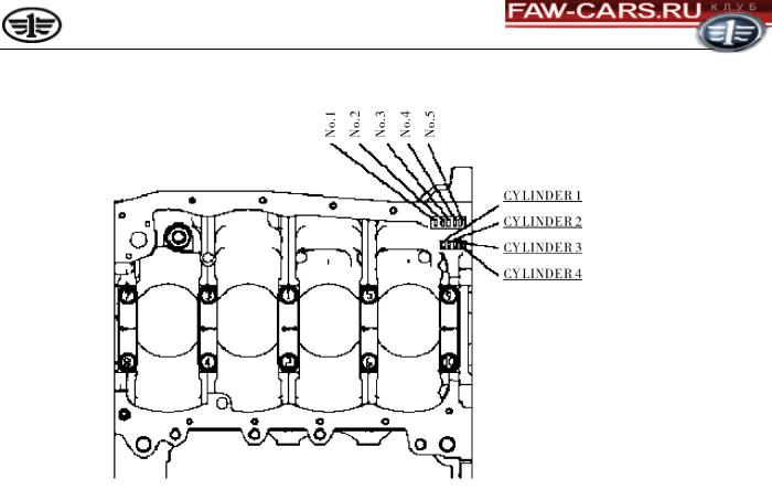
Cylinder block
The cylinder block has four cylinders, five main bearing supporting crankshaft main journals, equal cylinder center distance and gantry structure. Cylinder block and crankcase are integrated. Material is alloy cast iron. The weight is less than 28.7kg. The wall thickness is 3.5mm and the maximum wall thickness shall be not more than 4.5mm.
Cylinder block
Water jackets are provided on both sides of each cylinder to ensure a good cooling result. Water jacket thickness on both side walls is 4mm. Water jacket height is 110mm, which is a little higher than the stroke.
Main bearing cap material is iron-based powder metallurgy, which is integrated with main bearing seat of engine block. They are fully-support type structure, with reliable rigidity and strength. There is a forward arrow and number on main bearing cap. When assembling, the number shall be checked and followed.
In order to reduce the noise and vibration, reinforced rib is provided on side wall and around main bearing to form a rigid structure.
There are grouping numbers of cylinder hole, and grouping numbers of main bearing hole and main bearing shell on the bottom of engine block.
Cylinder block dimensions
Total height ×full length ×total width |
(mm) |
270.2×355.5×326.5 |
|
|
|
Cylinder bore |
(mm) |
73 |
|
|
|
Cylinder center distance |
(mm) |
80 |
|
|
|
Main bearing hole diameter |
(mm) |
φ50 |
|
|
|
17
Tianjin FAW
CA4GA5 Engine Maintenance Manual
Main bearing hole grouping mark
Character font is No. 4 printing form
Stamp horizontally
Front |
|
end |
Cylinder hole grouping mark |
Character font is No. 4 printing form
Stamp horizontally
Cylinder head and combustion chamber
The cylinder head adopts aluminum alloy casting, double top-mounted camshaft structure and is provided with water jacket to cool cylinder head. Combustion chamber is like a roof ridge and spark plug is installed at the center of combustion chamber to keep flame spread uniform.
The valve seat opening is a little declined type The intake valve seat opening inclination is 14°30′ and exhaust valve seat opening inclination is 15°12′. The cylinder head is pressed into valve seat opening. There are two lines of camshaft bearing supports on the cylinder head. The first camshaft bearing support is combined. The cylinder head height is enlarged and rigidity is increased. Combined camshaft bearing support is provided with lubricating oil slot. The cylinder head bolt head seat is position in deep place. Fuel injector is installed on the cylinder head.
18

Tianjin FAW
CA4GA5 Engine Maintenance Manual
Exhaust |
|
Intake |
|
|
|
Exhaust
Combustion
chamber
Rotational
flow inlet
Intake
Cylinder head and combustion chamber
1st camshaft bearing support
In order to increase combustion efficiency, air inlet adopts spiral-flow type to rotate gases in combustion chamber so as to increase the charging efficiency. The cylinder head is provided with longitudinal water channel.
Piston, piston rod and piston ring
Piston is made of aluminum casting alloy. There is a φ60.4 pit on the top (Note: piston top pit diameter of 1.3L engine is different from that of 1.5L engine) to enlarge combustion volume. There are two pits on the air intake side on the top of the piston to prevent it from colliding with intake valve. Piston is of three-ring short skirt type. Graphite coating is printed on the surface of piston. The first ring groove and some ring edges (including piston top) is oxidized to ensure safety and durability, resist heat load and mechanical load, and reduce the weight at the same time. Piston and cylinder block shall be matched to ensure fit clearance. The weight difference among four pistons of the same engine shall not be more than 6g. There is a forward mark (arrow) and piston outer diameter grouping number (A, B, C) printed on the top of the piston. Piston pin hole grouping adopts red and yellow. Piston skirt barrel line adopts hyperbolical cosine function. Barrel skirt and cylinder wall formed bidirectional wedge oil film make the skirt have higher bearing capacity and good lubrication. In addition, inclination in piston motion can avoid load on closed angle to reduce impact of the piston on cylinder wall.
In order to endure surface hardness of piston pin, inner and outer surfaces of the piston pin are carburized. Piston pin diameter adopts red and yellow marks on piston pin end face.
In order to reduce mechanical loss, 1st and 2nd piston rings shall be thin rings. Oil ring adopts two side rings and one grommet.
19

Tianjin FAW
CA4GA5 Engine Maintenance Manual
1st piston ring is barrel surface ring. The surface that contacts the cylinder is plated with hard chromium coat to reduce surface wear. 2nd piston ring is taper-face ring, which is treated by phosphorization. The surface of scraper blade in combination oil ring, which contacts the cylinder, is plated with hard chromium. Other surfaces are treated by phosphorization. Grommets go through tufftriding.
When installing piston ring, the surface with a mark shall be upward. Opening for each ring shall be separated by 120°.
Hard chrome plating
Mark
Hard chrome plating
Mark
Tufftriding
Hard chrome plating
Piston and piston ring
Connecting rod and connecting rod bearing shell
Connecting rod is forged by chrome steel, with high rigidity. When assembling connecting rod cap, forward marks shall be on the same side. When installing it on the engine, this surface shall face engine front. The weight difference among four connecting rods of four cylinders in the same group shall be no more than 3g. Connecting rod big end grouping marks (1 and 2) have two groups, which are printed on connecting rod body side. Connecting rod quality grouping mark (A, B, C, D, E) have five groups, which are printed on connecting rod cover.
Big end grouping mark
Forward mark
Quality grouping mark
Connecting rod
20
Tianjin FAW
CA4GA5 Engine Maintenance Manual
Connecting rod bearing shell includes upper half and lower half. Upper half is installed on connecting rod body and lower half on connecting rod cap. Connecting rod bearing shell (upper and lower half) is divided into four groups within specified thickness tolerance. The bearing shell is colored on both ends. Connecting rod bearing positioning lip is on the side. When assembling, in order to ensure fit clearance, select and assemble according to grouping dimension of related parts.
Connecting rod upper bearing shell
Connecting rod bearing shell location lip
Connecting rod lower bearing shell
Connecting rod bearing shell
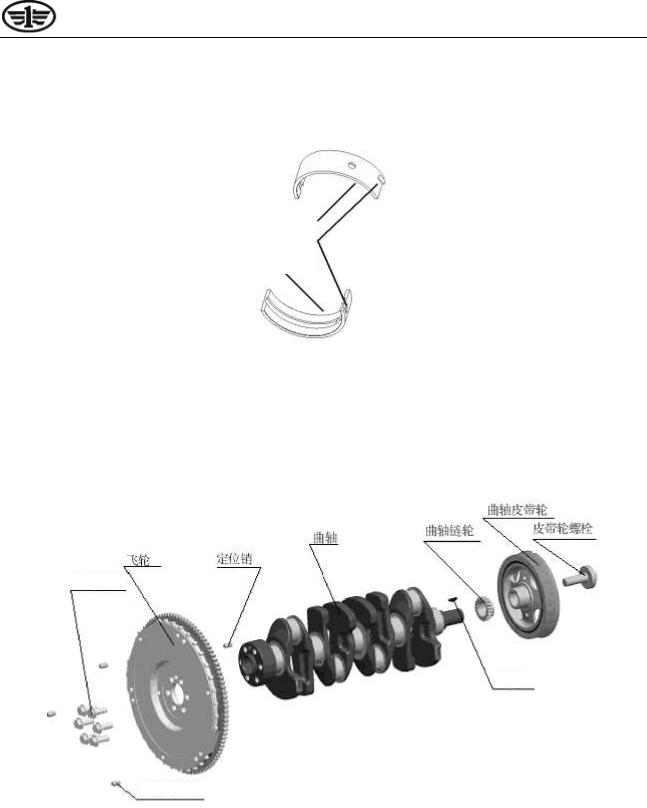
Crankshaft and bearing shell
Crankshaft is made of nodular cast iron, which consists of five main journals, eight pieces of balance weights, crank throw included angle 180°, with symmetrical plane. It has dynamic balance itself. But it bears inner bending moment to make crankshaft reach inner balance. Two groups of different balance weights are prepared.
The third main journal bears axial thrust. Two thrust shims made of mock silver are installed on both sides of cylinder block supporting the third main journal.
Balance weight removes all inherent vibration of the engine.
Connecting rod journal grouping code is stamped on the side of front balance weight. Main bearing journal grouping code is stamped on the side of rear balance weight.
Location pin
Main bearing journal and connecting rod journal of crankshaft adopt rolling fillet to increase fatigue strength.
Main bearing journal diameter of crankshaft mm |
46 |
|
|
Connecting rod journal diameter of crankshaft mm |
44 |
|
|
21
Tianjin FAW
CA4GA5 Engine Maintenance Manual
1st ~5th main bearing shells of crankshaft adopt the same aluminum-tin alloy bearing shell. Upper bearing shell is provided with one oil groove and oil hole. Positioning lip for bearing shell is on the side.
Crankshaft upper bearing shell
Bearing shell location lip
Crankshaft lower bearing shell
Crankshaft bearing shell
Flywheel
Crankshaft front end is provided with timing sprocket and crank shaft belt pulley. They are used to drive camshaft, water pump and generator, respectively.
|
|
|
Crankshaft belt pulley |
|
||
|
|
|
|
|
|
|
|
|
|
|
|
Belt pulley bolt |
|
|
|
Crankshaft sprocket |
||||
Crankshaft |
|
|||||
|
|
|
|
|
|
|
|
|
|
|
|
|
|
Flywheel |
|
Location pin |
Flywheel bolt
Semi-circle key
Pressure plate location pin
The flywheel with ring gear is installed on rear end of crankshaft by 6 bolts. The flywheel body has signal teeth used to output the engine speed signal. The specifications as follows:
Outer diameter mm |
242 |
|
|
Mass kg |
6.45 |
|
|
Gear ring tooth number |
103 |
|
|
Gear ring modulus |
2.54 |
|
|
22

|
|
Tianjin FAW |
|
CA4GA5 Engine Maintenance Manual |
|
|
|
|
|
|
|
|
|
|
|
|
|
|
|
|
|
|
|
|
|
|
|
||
|
Pressure plate surface diameter mm |
205 |
|
||
|
|
|
|
||
|
Rotating speed signal tooth number |
30 teeth |
|
||
|
|
|
|
||
|
Dynamic unbalance less than |
25gcm |
|
||
|
|
|
|
|
|
Crank pulley
In order to reduce torsional vibration, the engine adopts spoke type V-belt crank pulley with shock absorber to reduce radiation noise on front end of the engine so as to reduce noise of complete machine and reduce weight.
|
Crank pulley specifications |
|
|
|
|
Crank pulley outer diameter (mm) |
|
144 |
|
|
|
V-belt groove angle |
|
40° |
|
|
|
V-belt groove number |
|
6 |
|
|
|
Dynamic unbalance is less than |
|
5gcm |
|
|
|
Crankshaft oil seal
Front and rear oil seals of crankshaft are T structure with spiral line (spiral groove) in order to prevent oil leakage. T oil seal applies spiral groove oil pump. When crankshaft is running, oil is forced to return to the engine. T oil seal has obvious sealing characteristics.
Rear oil seal assembly
Rear oil seal seat assembly
|
|
|
Rear seal oil of crankshaft |
|
||
|
|
|
|
|
|
|
|
Chain chamber |
|
|
|
|
|
|
cover assembly |
|
|
|
|
|
|
|
|
|
Chain chamber |
|
|
|
|
|
|
|
cover assembly |
|
|
|
|
|
|
|
|
|
|
|
|
|
Front oil seal |
|
|
Front oil seal |
|
|
|||
|
|
|
|
assembly |
|
|
|
assembly |
|
|
|
|
|
|
|
|
|
|
|
|
|
|
|
|
|
|
|
Front seal oil of crankshaft
Oil seal specification
23

|
|
Tianjin FAW |
|
|
CA4GA5 Engine Maintenance Manual |
|
||
|
|
|
|
|
|
|
||
|
|
|
|
|
|
|
||
|
|
|
|
|
|
|
|
|
|
|
|
|
|
|
|
|
|
|
Item |
|
|
Inner diameter |
Outer diameter |
Thickness |
|
|
|
|
|
|
|
|
|
||
|
|
|
|
|
|
|
||
|
Front oil seal (mm) |
|
φ33.8 |
φ49 |
6 |
|
||
|
|
|
|
|
|
|
||
|
Rear oil seal (mm) |
|
φ72.1 |
φ89 |
8.5 |
|
||
|
|
|
|
|
|
|
|
|
Cylinder head cover assembly
Cylinder head cover assembly is cast by aluminum alloy, with many arc surfaces. A ventilation baffle is used to separate the engine oil in blow-by gas and then oil flows into intake pipe through crankshaft case vent valve assembly for combustion.
Cylinder head cover assembly
Section 2 Valve actuating mechanism
Valve actuating mechanism of CA4GA5 engine adopts double top-mounted camshafts with intake VCT controller assembly driven by timing chain drive belt. The camshaft is fastened on the upper part of cylinder head, which is supported by five bearing supports to drive two intake valves and two exhaust valves. This is a typical direct drive of valve. It has high rigidity and good follow-up characteristics within the whole working range. Similarly in-line intake and exhaust valves can get an almost smooth torque characteristic curve and increase passing capacity of air flow to ensure thorough intake and exhaust.
Timing chain assembly and sprocket
24
|
|
Tianjin FAW |
|
|
|
CA4GA5 Engine Maintenance Manual |
|
||
|
|
|
|
|
|
|
|
||
|
|
|
|
|
|
|
|
||
|
|
|
|
|
|
|
|
|
|
|
Timing chain |
|
|
|
|
|
|
||
|
|
|
|
|
|
|
|
|
|
|
Pitch circumference |
|
Pitch mm |
Pieces |
|
Width mm |
|
||
|
length mm |
|
|
|
|||||
|
|
|
|
|
|
|
|
||
|
|
|
|
|
|
|
|
|
|
|
1054 |
|
|
6. 35 |
166 |
|
11. 5 |
|
|
|
|
|
|
|
|
|
|
|
|
For this engine, timing chain drives exhaust camshaft to ensure stable running and low noise. When timing chain is bent, it will reduce strength greatly. Therefore, timing sprocket shall not be bent. Do not make water or other chemical liquids contact timing chain during the course of using. These contaminants will corrode chain link pieces. Timing chain has two groups and one yellow link piece which is timing mark.
Timing mark
Timing mark
Timing mark
Timing chain
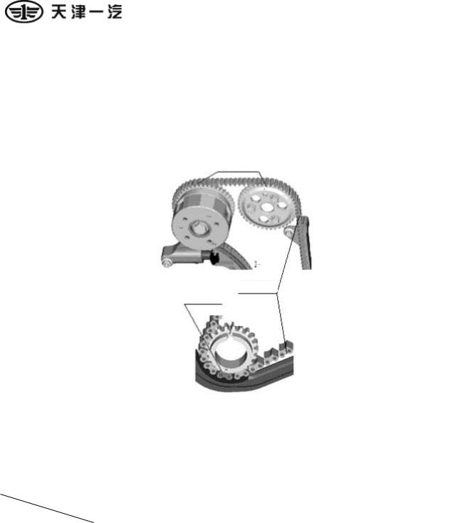
Sprocket
There are four sprockets. The first is exhaust camshaft sprocket installed on exhaust camshaft; the second is crankshaft sprocket installed on crankshaft; the third is a sprocket installed on engine oil pump; the fourth is a sprocket installed on VCT controller assembly. Each sprocket has engagement mark (except the sprocket on engine oil pump). When assembling, it shall align with the mark on the chain.
|
Exhaust camshaft |
Crankshaft sprocket |
Engine oil |
VCT controller assembly |
|
sprocket |
pump sprocket |
sprocket |
|
|
|
|||
|
|
|
|
|
Number of teeth |
42 |
21 |
25 |
42 |
|
|
|
|
|
Outer diameter |
83 |
40. 5 |
48. 6 |
83 |
|
|
|
|
|
Chain tensioner assembly and chain tension arm assembly
Open the chain tensioner spring to eject tensioning ball of chain tensioner to provide appropriate tension for chain tensioner assembly so as to ensure reliable drive and prolong service life of timing chain. Parts for tensioner are free of maintenance.
25

Tianjin FAW
CA4GA5 Engine Maintenance Manual
Chain tensioner assembly
Chain tension arm assembly
Chain tensioner assembly and chain tension arm assembly
Camshaft
Intake and exhaust camshaft are made of cold shock alloy cast iron. Cam included angle is 90°. Exhaust camshaft assembly drives intake camshaft assembly. The first journal of intake camshaft assembly has phase advance and delayed oil line.
Target wheel
Intake camshaft
Exhaust camshaft
VCT controller assembly
Exhaust camshaft sprocket
Intake and exhaust camshaft assembly
26

|
|
Tianjin FAW |
|
|
CA4GA5 Engine Maintenance Manual |
|
||
|
|
|
|
|
|
|
||
|
|
|
|
|
|
|
||
|
|
|
|
|
|
|
|
|
|
|
|
|
|
Camshaft specifications |
|
|
|
|
|
|
|
|
|
|
|
|
|
|
Item |
|
|
1st journal dimension |
Other journal dimension |
Tip height (mm) |
|
|
|
|
|
(mm) |
(mm) |
|
||
|
|
|
|
|
|
|
||
|
|
|
|
|
|
|
||
|
Exhaust camshaft |
|
26(-0.035~-0.051) |
23(-0.035~-0.051) |
41.1 |
|
||
|
|
|
|
|
|
|
||
|
Intake camshaft |
|
32(0,-0.016) |
23(-0.035~-0.051) |
41.2 |
|
||
|
|
|
|
|
|
|
|
|
3.Intake camshaft assembly is driven by exhaust camshaft assembly, that is, exhaust camshaft sprocket drives VCT controller and sprocket on the intake camshaft sprocket assembly. VCT controller and intake camshaft sprocket assembly are fixed on intake camshaft assembly.
4.Intake valve, exhaust valve and valve spring
|
Full length mm |
Valve head diameter mm |
Valve stem diameter mm |
|
|
|
|
Intake valve |
88.1 |
27.5 |
5.0 |
|
|
|
|
Exhaust valve |
88.65 |
23 |
5.0 |
|
|
|
|
Intake valve and exhaust valve are made of chrome-silicon steel. Head diameter is designed to be larger so as to increase intake and exhaust efficiency. Valve spring is made of chrome-silicon steel. At high speed, it has high follow-up performance and natural frequency.
Free state specifications of valve spring
Free length mm |
Mean diameter of |
Steel wire diameter |
Total number of |
Effective number |
|
spring mm |
mm |
turns |
of turns |
||
|
|||||
|
|
|
|
|
|
45.2 |
16.6 |
3.2 |
9 |
7 |
|
|
|
|
|
|
|
Assembled state of valve spring |
|
|
|
|
Length mm |
|
Load N |
|
|
|
37 |
|
160±8 |
|
|
|
29.5 |
|
399±20 |
|
|
|
Spring rigidity: 31.9N/mm |
|
|
27

Tianjin FAW
CA4GA5 Engine Maintenance Manual
Valve tappet
Valve spring
Valve spring
Gasket
Intake valve
Exhaust valve
4. Valve tappet
Valve tappet is cylindrical to ensure uniform force when the valve moves, and has high follow-up performance. Tappet surface is carbonitriding. After carbonitriding, actual thickness of tappet is stamped on the inner top. In order to keep valve clearance within specified range, select integrated tappet with corresponding thickness according to actual measuring result when installing the engine.
5. VCT controller and intake camshaft sprocket assembly
VCT controller and intake camshaft sprocket assembly control cam peach-shaped phase position of intake camshaft assembly by using engine oil pressure difference, and change intake camshaft intake angle with engine working conditions changing so as to save fuel.
VCT controller assembly
28

Tianjin FAW
CA4GA5 Engine Maintenance Manual
Section 3 Lubrication System
The engine adopts pressure and splash lubrication types, forced oil supply and full-flow filter.
Engine oil pumped from oil pan by oil pump goes through oil catcher and goes into engine oil filter, main oil duct and then goes to each main bearing journal of crankshaft, connecting rod journal, camshaft bearing support, OCV control valve assembly and VCT controller assembly. Exhaust camshaft supplies oil to exhaust bearing support by its oil line for lubrication. Intake camshaft supplies oil to each bearing support on the intake side by its oil line to lubricate friction pair surface enough.
Other parts of the engine, such as clearance between camshaft peach, piston, piston ring and cylinder wall; crankshaft thrust shim, timing chain and engine oil pump drive sprocket adopt splash lubrication.
Cylinder head oil channel
|
1st bearing support |
|
|
1st bearing support |
|
|
|
OCV control valve |
|
|||||||
|
for intake camshaft |
|
|
for exhaust |
|
|
|
|
|
filter |
|
|||||
|
|
|
|
|
camshaft |
|
|
|
|
|
|
|
|
|
|
|
|
|
|
|
|
|
|
|
|
|
|
|
|
|
|
|
|
|
|
|
|
|
|
|
|
|
|
|
|
|
|
|
|
|
|
|
|
|
|
|
|
|
|
|
OCV control valve |
|
|||||
|
|
|
|
|
|
|
|
|
|
|
assembly |
|
||||
|
|
|
|
|
|
|
|
|
|
|
|
|
|
|
|
|
|
|
|
|
|
|
|
|
|
|
On |
|
|
|
|
|
|
|
|
|
|
|
|
|
|
|
|
|
|
Off |
|
|
|
|
|
|
|
|
|
|
|
|
|
|
|
|
|
|
|
|
|
|
|
|
|
|
|
|
|
|
|
|
|
|
|
|||
|
|
|
|
|
|
|
|
|
|
|
|
|||||
|
|
|
|
|
|
|
|
|
||||||||
Each cam bearing |
|
|
Each cam bearing |
|
|
|
1st bearing support |
|
|
|||||||
support for intake |
|
|
support for exhaust |
|
|
for intake camshaft |
|
|
||||||||
|
|
|
|
|
|
|
|
|
|
|
|
|
|
|
|
|
VCT controller assembly
1st bearing support for intake camshaft
OCV control valve filter
Oil pan
Main bearing holes for all connecting rods
1st main bearing cap |
|
Other main bearing |
|
|
caps |
|
|
|
Main oil channel
Chain lubrication nozzle
Engine oil filter
Relief valve |
|
|
|
Main oil channel |
|
assembly |
|
|
|
|
|
|
|
|
|
|
|
Engine oil pump
Engine oil coarse strainer
Lubrication system block diagram
(1) Engine oil pump assembly
29

Tianjin FAW
CA4GA5 Engine Maintenance Manual
Rotor engine oil pump assembly is installed on the cylinder block, driven by crankshaft sprocket through timing chain. Outer and inner rotors of engine oil pump are installed on cylinder block. The relief valve is installed on cylinder block oil line. When engine oil pump reaches the oil supply pressure, the relief valve will work and drain oil. Drained lubrication oil returns to the engine oil pump. The engine oil pump is provided with drive sprocket used to drive engine oil pump.
|
|
Engine oil pump assembly |
|
|
Engine oil pump assembly specifications |
|
|
|
Type |
Cycloid curve |
|
|
|
|
|
4.5 |
(Output pressure 150KPa, engine oil pump speed 588r/min) |
|
|
|
Output flow (L/min) |
14 |
(Output pressure 400KPa, engine oil pump speed 1680r/min) |
|
|
|
|
41 |
(Output pressure 450KPa, engine oil pump speed 5040r/min) |
|
|
|
Relief valve is an integral structure. Spring is compressed in plunger and housing.
Free state specifications of relief valve spring
Free length mm |
Mean diameter of |
Steel wire diameter |
Total number of |
Effective number of |
||
spring mm |
mm |
turns |
turns |
|||
|
||||||
|
|
|
|
|
|
|
43.6 |
9.8 |
1.4 |
12 |
10 |
||
|
|
|
|
|
|
|
|
Assembled state of relief valve spring |
|
||||
|
|
|
|
|
|
|
|
Length mm |
|
|
Load N |
|
|
|
|
|
|
|
|
|
|
30.9 |
|
|
50.85 |
|
|
|
|
|
|
|
|
|
|
24.6 |
|
|
76.2 |
|
|
|
|
|
|
|
|
|
Spring rigidity: 4N/mm
30
 Loading...