

Page 1

FN 4000
DF 6000
TECHNICAL
MANUAL
2010
DIGITAL
SYSTEMS
Page 2
INTRODUCTION
Notice to the installer and user
This edition contains helpful information on the operation and installation of Farfisa video intercoms systems.
In order to make the systems work properly it is necessary to install only
Farfisa equipment, keeping strictly to the items referred to in each
diagram.
Read all the notes carefully, (even the small ones) in each installation
scheme and the working instructions of the system given in the
following pages.
For the sake of clarity, please notice that the sequence of the terminals
of each article
has not been followed. Only the terminal code (letter and/
or number) is valid not the graphic sequence.
The items may have more terminals than the ones in the installation
diagrams. The excess terminals must not be used.
Check the integrity of the product after removing it from the packing.
Packing materials (such as plastic bags, cardboard, polystyrene
foam, etc.) must be kept out of the reach of children.
The manufacturer cannot be held responsible for possible damages
caused by improper, erroneous and unreasonable use.
The cable runs of any intercom and video-intercom system must be
kept separate from the mains or any other electrical installation as
required by International Safety Standards.
WARNINGS
An all-pole mains switch with a contact separation of at least
3mm in each pole shall be incorporated in the electrical installation of the building.
Before connecting the unit, make sure its data correspond to
those of the mains.
The apparatus shall not be exposed to dripping or splashing.
For correct operation make sure that ventilation or heat dissipation openings are not obstructed.
Do not open or tamper with power supply or video intercom
apparatus when they are ON. There is high voltage inside.
European Mark of conformity to the EEC
Directives.
CE MARK
The CE mark ensures that the product complies with the requirements of the
European Community Directives in force; in particular, Electrical Safety LVD73/23,
Electromagnetic Compatibility EMC89/336 and Telecommunication Terminals
R&TTE99/5 Directives.
As set forth by the Directives, the technical documentation and Conformity Declarations are available in the Company’s offices for verifications and controls by
competent Authorities.
Avoid bumping and hitting the video intercom apparatus, it
could break of the CRT with consequent projections of fragmented glass.
For installation or maintenance refer only to qualified personnel.
Mark of VDE a German Testing and Certification Institute.
R
T
E
I
C
F
I
C
M
A
E
T
T
I
S
O
Y
N
S
I
S
O
9
0
0
1
:
2
0
0
SGS
0
Quality assured firm according to standard
ISO 9001:2000 certified SGS.
Italian Association of Electrotechnical and
Electronic Industries
Page 3

Technical Manual 10 Edition 2010
FN 4000
INDEX
Main features
Typical installations
Door stations (push-button panel)
Internal stations
Power supplies
Service modules
Doorkeeper exchanger
Installation notes
Conversion of video signal
Intercom installation diagrams
Si 50CD/1 Digital intercom system with doorkeeper exchanger and without door stations
Si 51CD/3 Digital intercom system with 1 door station. With or without doorkeeper exchanger
Si 52CD/3 Digital intercom system with 2 or more door stations. With or without doorkeeper exchanger
Si 56CD/10 Digital intercom system with secondary door stations and 1 common main door station (multiple entrance). With or
without doorkeeper exchanger
Si 57CD/1 Digital intercom system with secondary door stations and 2 common main door stations (multiple entrance). With
or without doorkeeper exchanger
Video intercom installation diagrams
Si 51VD/5 Digital video intercom system with 1 video door station. With or without doorkeeper exchanger
Si 51VD/23 Digital video intercom system with 1 video door station. With or without doorkeeper exchanger
Si 51VD/24 Digital video intercom system with 1 video door station with surveillance camera. With or without doorkeeper exchanger
(coaxial cable)
Si 52VD/1 Digital video intercom system with 2 video door stations. With or without doorkeeper exchanger
Si 52VD/14 Digital video intercom system with 2 video door stations. With or without doorkeeper exchanger
Si 52VD/2 Video intercom system with 2 door stations one of which is only audio. With or without doorkeeper exchanger
cable)
Si 53VD/1 Digital video intercom system with 3 video door stations. With or without doorkeeper exchanger
Si 53VD/2 Video intercom system with 3 door stations one of which is only audio. With or without doorkeeper exchanger
cable)
Si 56VD/21 Digital video intercom system with secondary video door stations and 1 common main video door station (multiple
entrance). Doorkeeper exchanger with monitor and surveillance camera
Si 56VD/31 Digital video intercom system with secondary video door stations and 1 common main video door station (multiple
entrance). With or without doorkeeper exchanger
Si 56VD/23 Digital video intercom system with secondary door stations only audio and 1 common main video door station (multiple
entrance). With or without doorkeeper exchanger
Si 56VD/24 Digital video intercom system with secondary video door stations and 1 common main door station only audio (multiple
entrance). With or without doorkeeper exchanger
Si 57VD/1 Digital video intercom system with secondary video door stations and 2 common main door stations (multiple entrance).
Doorkeeper exchanger with monitor and surveillance camera
Si 51VD/14 Digital video intercom system with 1 video door station using multiple decoding modules. With or without doorkeeper
exchanger
Si 51VD/26 Digital video intercom system with 1 video door station using multiple decoding modules. With or without doorkeeper
exchanger
Si 56VD/25 Digital video intercom system with secondary video door stations, 1 common main door station (multiple entrance)
using multiple decoding modules. With or without doorkeeper exchanger
Si 57VD/8 Digital video intercom system with secondary video door stations, 2 common main door stations (multiple entrance)
using multiple decoding modules. With or without doorkeeper exchanger
(coaxial cable)
(twisted pair)
(twisted pair)
(coaxial cable)
(coaxial cable)
(coaxial cable)
(coaxial cable)
(coaxial cable)
(coaxial cable)
(coaxial cable)
(twisted pair)
(coaxial cable)
(twisted pair)
(coax.
(coaxial cable)
(coax.
Page
2
3
5
56
93
94
99
103
108
110
111
113
115
117
119
120
121
123
125
127
129
131
133
135
137
139
141
143
145
147
149
151
153
F
N
Installation diagrams
DF6000 digital system
Product list
154
4
171
0
240
0
0
1
(MT10 - Gb2010)
Page 4

MAIN FEATURES
I
The Farfisa FN4000 digital system has been developed with advanced
N T E R C O M S Y S T E M S *
technology and microprocessors to allow for the installation of intercom
and video intercom systems with medium or high number of users using
a reduced number of wires (5 for intercom systems, 5 plus coaxial cable
or twisted pari for video intercom systems). Different combinations of
the units provide a wide range of functions in order to satisfy multiple
user’s needs.
system platform
The FN4000 system is the first ACI Farfisa product developed on the
tion of specifications both physical and software. Based on this, sys-
tems are developed in order to make services for flats and houses. It is
a new possibility for installers, who will be able to offer compatible and
flexible systems that can communicate with the FN4000 system (through
V
for domestic automation.
NET
platform. Technically this platform is made up of a combina-
NET
) to expand the existing installation and offer new opportunity
NET
I D E O I N T E R C O M S Y S T E M S
Type of installation
The Farfisa digital system allows the realisation of many different types
of installation.
• Intercom systems
• Video intercom systems
• Mixed intercom/video intercom systems/with telephone interfaces
• Systems with doorkeeper exchanger
• Systems with 1 or more equally important door stations (without
exchanger)
• Systems with 1 or more main door stations and secondary door
stations (with exchanger)
Choosing the equipment
When choosing the articles for the installation, the following aspects
must be considered:
• the user’s needs
• the number of users
• the installation possibilities
• the possible locations.
The following options are available for door stations:
• main and secondary door stations with digital push-button panels
(recommended for medium-large installations)
• main and secondary door stations with conventional push-button
panels and digital encoder (recommended for small-medium installations)
• secondary door stations with conventional push-button panels without digital encoder (recommended for one user or up to 4 calls)
As regards internal stations, apart from the esthetical model, the type
of decoder:
• internal stations with integrated decoding (simple and rapids installation)
• single decoding module (a little more expensive, but easier to
connect and install)
• multiple decoding module (cost optimization of single intercom; the
F
N
decoding module must be located on the stage outside the apartments)
Systems with one or more door stations
• digital or conventional push-button panels with digital encoder
• coded call with 12-button keypad on 4-digit display or 2x16-character LCD
• call by means of conventional buttons with digital encoder
• call by means of conventional button without digital encoder (recommended for a few users)
• call reception by means of electronic DIN-DON or continuous note for
floor calls or analogue standard secondary door stations and without
digital encoder
• timed conversation (1-minute duration with possibility of increasing
conversation time by pressing a specific button on the push-button
panel)
• acoustic signal of conversation end
• private audio-video and lock function (only the called user can see,
talk and release lock)
• coded lock release directly from the digital push-button panel (by
means of programmable personal code)
• busy signal on door stations
• busy signal on intercoms and video intercoms during conversation
Systems with doorkeeper exchanger
(in addition to the functions above)
• Day-Night operating mode: in day mode all calls are received by the
doorkeeper exchanger; in night mode calls are directly transferred to
the users
• call display on alphanumeric 32-character LCD
• possibility of memorising and booking calls at the doorkeeper
exchanger during conversations in progress – they will be automatically made when the line is free
• communication between 2 internal stations
• possibility of connecting an internal station with a door station
• possibility of using a wide range of Farfisa intercoms or video
intercoms
• possibility of connecting a monitor at the exchanger with automatic
switching ON and visualisation of the image from the last calling door
station
• direct dialling – the desired user can be called directly from the door
station
• call transfer – all calls to the doorkeeper exchanger can be transferred to a programmed intercom
Connection of video signal using coaxial cable or twisted pair
With the Studio videointercom series or using the video converter
module can also be chosen the type of installation.
• connection of video signal using a 75Ω coax cable and video
distributors DV2, DV4 and 476
• connection of video signal using a twisted pair and video distributors
DV2D and DV4D.
4
0
0
0
2
(MT10 - Gb2010)
Page 5
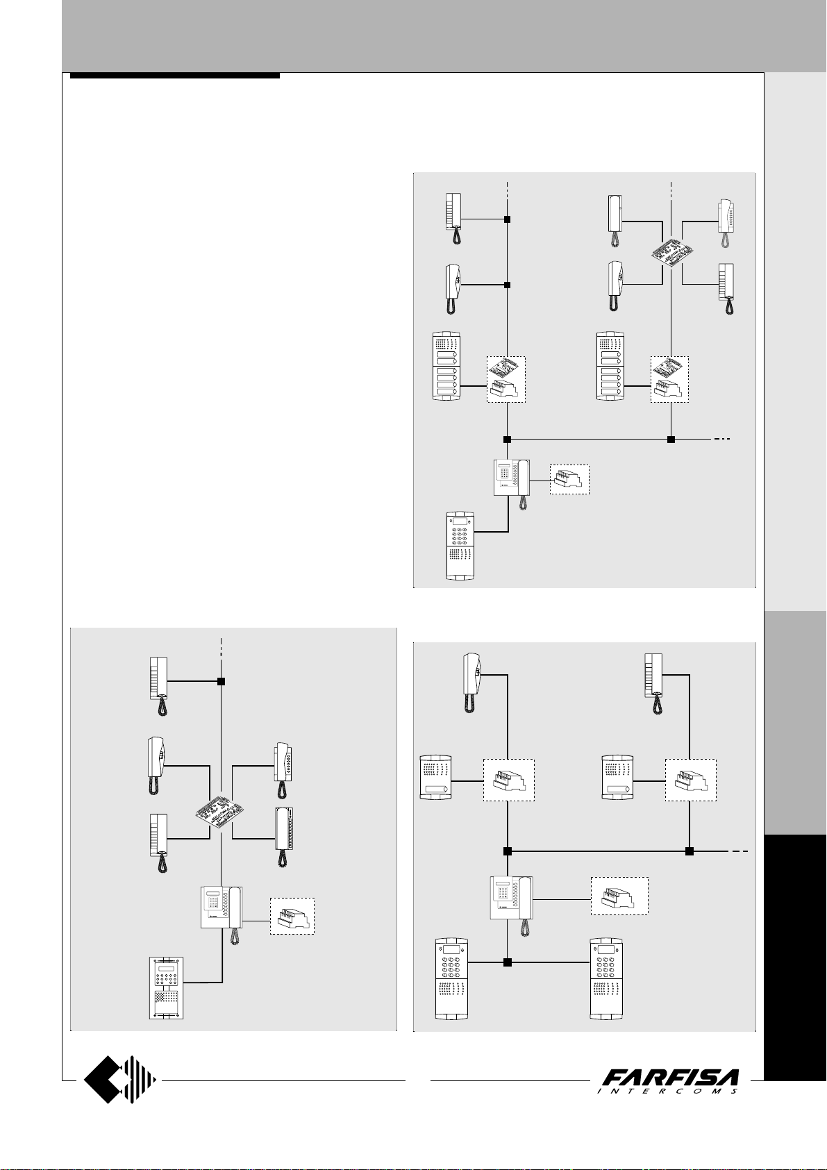
TYPICAL INSTALLATIONS
INTERCOM SYSTEMS
- doorkeeper exchanger only
- 1 door station with/without doorkeeper exchanger
- multiple main door stations with/without doorkeeper exchanger
- 1 or multiple main door stations, distribution on multiple
risers and with/without doorkeeper exchanger
- 1 or multiple main door stations, distribution on multiple
risers with secondary door stations and with/without doorkeeper exchanger
- 1 or multiple main door stations, one-way secondary door
stations and with/without doorkeeper exchanger
Installation example of an intercom system with digital main station, secondary door stations with digital encoder for conventional push-button panels and intercoms with integrated decoding and/or multiple decoding module
changer).
(optional doorkeeper ex-
I
N T E R C O M S Y S T E M S *
V
I D E O I N T E R C O M S Y S T E M S
Installation example of an intercom system with one digital
station and intercoms with integrated decoding and/or multiple
decoding module
(optional doorkeeper exchanger).
Installation example of an intercom system with multiple digital
main door stations, one-way secondary door stations and intercoms with integrated decoding
(optional doorkeeper exchanger).
F
N
4
3
(MT10 - Gb2010)
0
0
0
Page 6
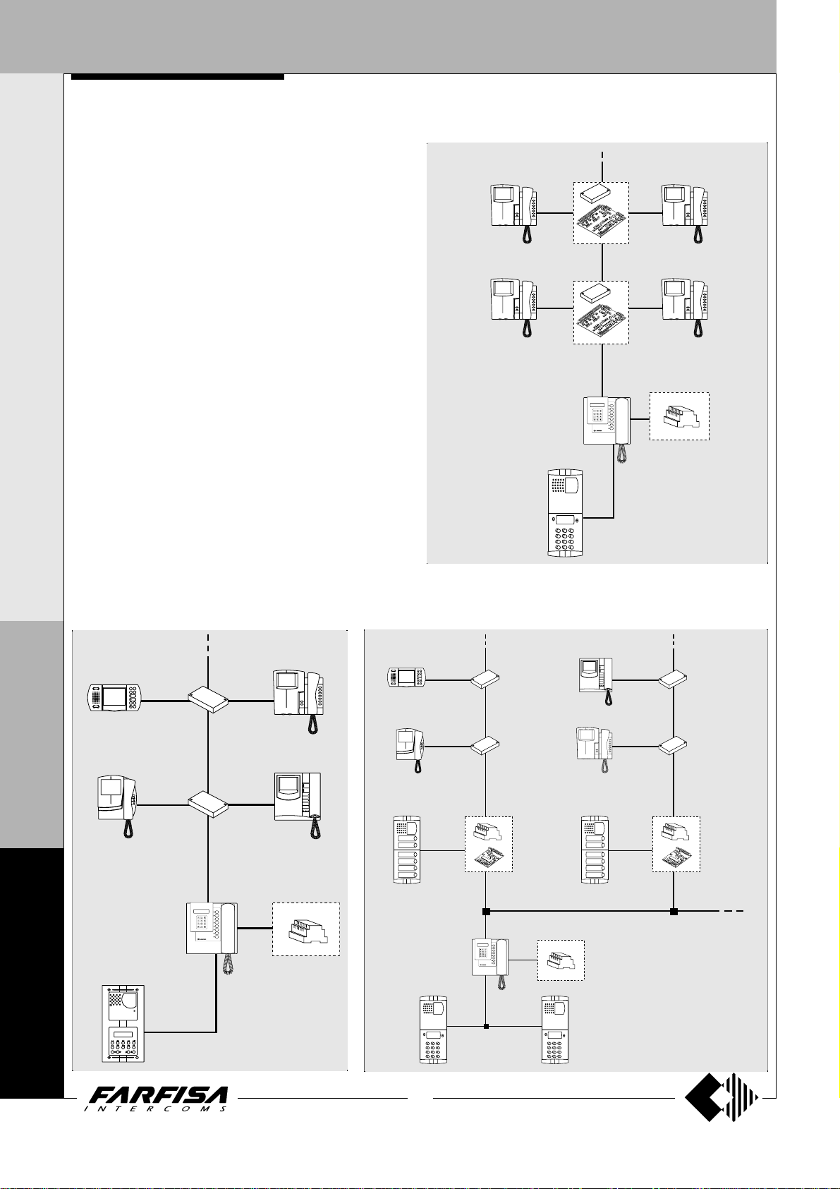
TYPICAL INSTALLATIONS
I
N T E R C O M S Y S T E M S *
VIDEO INTERCOM SYSTEMS
- doorkeeper exchanger only with surveillance camera
- 1 video door station with/without doorkeeper exchanger
- multiple main video door stations with/without doorkeeper
exchanger
- 1 or multiple main video door stations, distribution on multiple
risers and with/without doorkeeper exchanger
- 1 or multiple main video door stations, distribution on multiple
risers with audio-video secondary door stations or only audio
and with/without doorkeeper exchanger
- 1 or multiple main video door stations, one-way secondary
door stations and with/without doorkeeper exchanger
V
I D E O I N T E R C O M S Y S T E M S
Installation example of a video intercom system with video digital
door station and video intercoms with multiple decoding module
(optional doorkeeper exchanger).
(optional)
Installation example of a video intercom system with
one digital video door station and video intercoms
with integrated decoding
changer).
(optional doorkeeper ex-
F
N
4
Installation example of a video intercom system with main digital video door
station, secondary door stations with digital encoder for conventional pushbutton panels and intercoms with integrated decoding
exchanger).
(optional doorkeeper
0
0
0
4
(MT10 - Gb2010)
Page 7
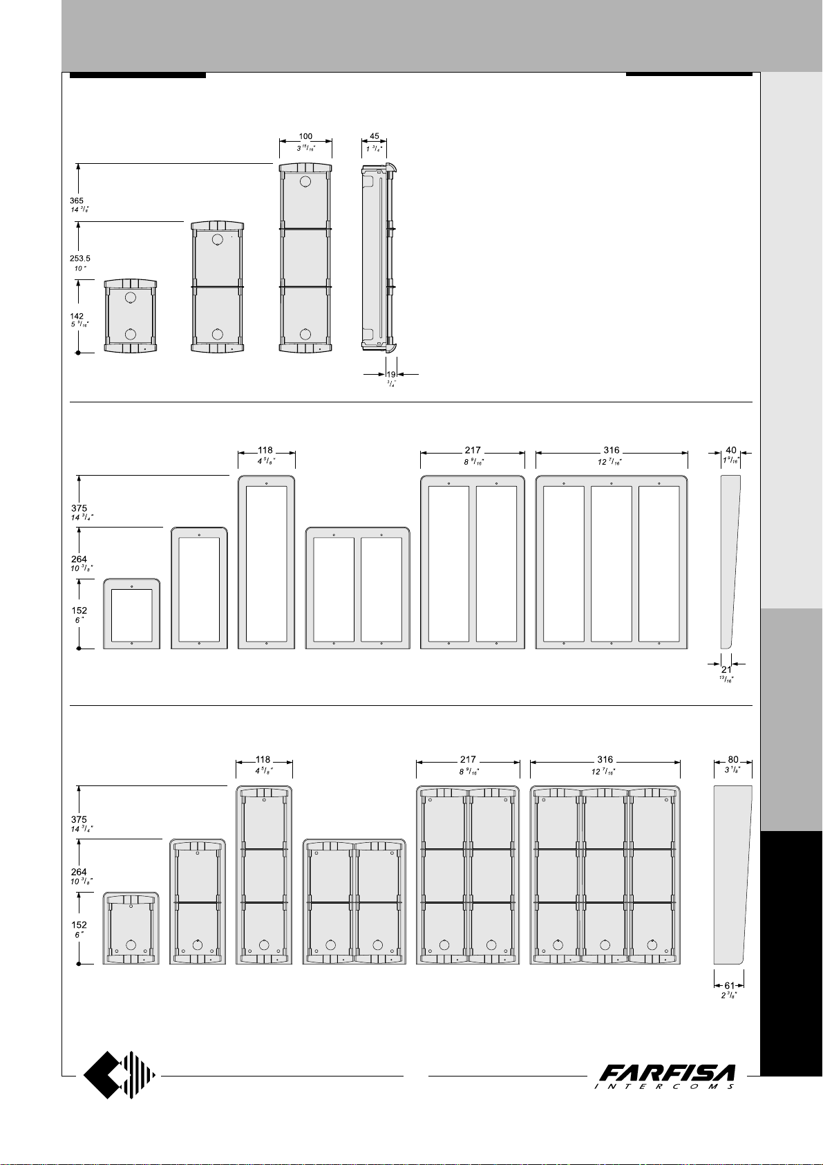
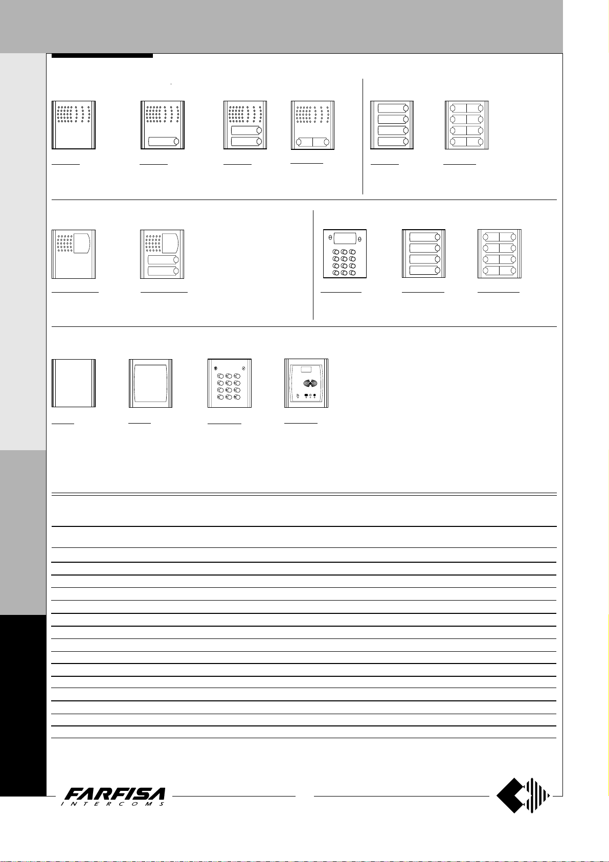
DOOR ST A TIONS
Module frames complete with back box
PL 71 PL 72 PL 73
Hood covers
PROFILO SERIES
I N T E R C O M S Y S T E M S * V I D E O I N T E R C O M S Y S T E M S
Push-button panels in extruded aluminium and
steel push-buttons made up of modular elements. Suitable for the most diverse installation requirements. The careful selection of
modules allows for multiple application opportunities; from one-way installations to blocks of
flats; from intercom to video intercom installations.
The optimized size of modules allows for easy
installation on the gage jamb.
PL 81 PL 83PL 82 PL 84 PL 86 PL 89
Rain shelters with module frames
PL 91 PL 93PL 92 PL 94 PL 96 PL 99
P
R
O
F
I
L
O
F
N
4
0
0
5
(MT10 - Gb2010)
0
Page 8
DOOR ST A TIONS
I N T E R C O M S Y S T E M S * V I D E O I N T E R C O M S Y S T E M S
Modules with door speaker integrated
Push-button modules
PL 10P
without call buttons
PL 11P
with 1 call button
Video modules with door speaker integrated
For specifications see
page 7.
PL 40PCDG
without call buttons
and with color camera
PL 42PCDG
with 2 call buttons and
color camera
Modules: blank, number and access control
PL 20
Blank module
PL 50
number module
FC 52PL
Keypad module
for access control
(see characteristics on page 8).
P
PL 12P
with 2 call buttons
PL 122P
with 2 call buttons
(2 row)
Modules: digital push-button and digitiser
TD4100PL
with 12 buttons
FP 52PL
Proximity reader for
access control
characteristics on
page 8).
(see
PL 24S
with 4 call buttons
CD4134PL
with 4 call buttons
(1 row)
PL 228S
with 8 call buttons
(2 row)
CD4138PL
with 8 call buttons
(2 row)
R
O
Technical characteristics of PROFILO modules terminal boards
F
PL10P PL11P PL12P PL122P PL50 PL24S PL228S PL40PCDG PL42PCDG
I
1111 1 1
L
2222 2 2
3333 3 3
O
4444 4 4
---- -A-A-- AAAA AA+A+
C C C(C2) C
F
N
4
L- L- L- L- L- LL+ L+ L+ L+ L+ L+
0
P1 P1 P1 P1
P2 P3(C2) P2
VV
MM
++
EC EC
0
0
6
(MT10 - Gb2010)
Reception audio line
Transmission audio line
Power supply input for electric door speaker (6÷12Vdc)
Audio ground
Ground for Led
AC or DC power supply input for nameplate Led (12Vac-dc)
Call push-buttons common
Call push-button
Call push-button
Video signal output (coaxial cable)
Video ground (coaxial shield)
Positive voltage input for camera and Led (12Vdc)
Camera enable input (ground command)
AC power supply input or ground for service Led
AC or DC power supply input for service Led (12Vac-dc)
Page 9

DOOR ST A TIONS
Video modules with integrated audio amplifier
I N T E R C O M S Y S T E M S * V I D E O I N T E R C O M S Y S T E M S
PL40PCDG. Modules complete with:
- CCD color camera with autoiris, fixed 3.6mm
lens and 6 white LED’s.
- amplified speaker unit with volume
adjustment of 2 channels (reception and
transmission)
- aluminium front plate with transparent screen
- horizontal and vertical adjustments
- red operation LED
PL42PCDG.
Same as PL40PCDG, with 2 call buttons and
name plate panel with transparent screen and
green LED backlighting.
Terminals
1 Reception audio line
2 Transmission audio line
3 Power supply input for electric door speaker
(6÷12Vdc)
4 Audio ground
- Ground for Led
+ Positive voltage input for camera and Led
(12Vdc)
C Call push-buttons common
P1-P2 Call push-buttons
V Video signal output (coaxial cable)
M Video ground (coaxial shield)
EC Camera enable input *
L- Negative power supply input for service Led
L+ Positive power supply input for service Led
* Operating timed mode if connected to the EC
terminal of the push-button panel or continu-
ous mode if grounded.
Technical data
Power supply 12±1Vdc
Operating current 0.4A
Video signal output 1Vpp on 75Ω
Video signal standard PAL
Minimum illumination 2.5 Lux
White balance auto
Led's 6 white
Sensor CCD 1/3" color
Number of pixels 291,000
Horizontal frequency 15,625Hz
Vertical frequency 50Hz
Lens 3.6mm
Focus 0.6m ÷ ∞
Autoiris electronic
Horizontal adjustment ± 15°
Vertical adjustment ± 15°
Operating temperature -10°÷+40°C
Max. permissible humidity 80%RH
Adjustments
You can manually change the camera framing
by unloosening and adjusting the horizontal
and vertical screws in the desired direction.
(±15°)
Audio adjustments
If necessary, it is possible to adjust the volume
of the 2 channels audio opportunely varying the
external knobs.
P
R
O
F
I
L
O
F
N
4
0
7
(MT10 - Gb2010)
0
0
Page 10
DOOR ST A TIONS
I N T E R C O M S Y S T E M S * V I D E O I N T E R C O M S Y S T E M S
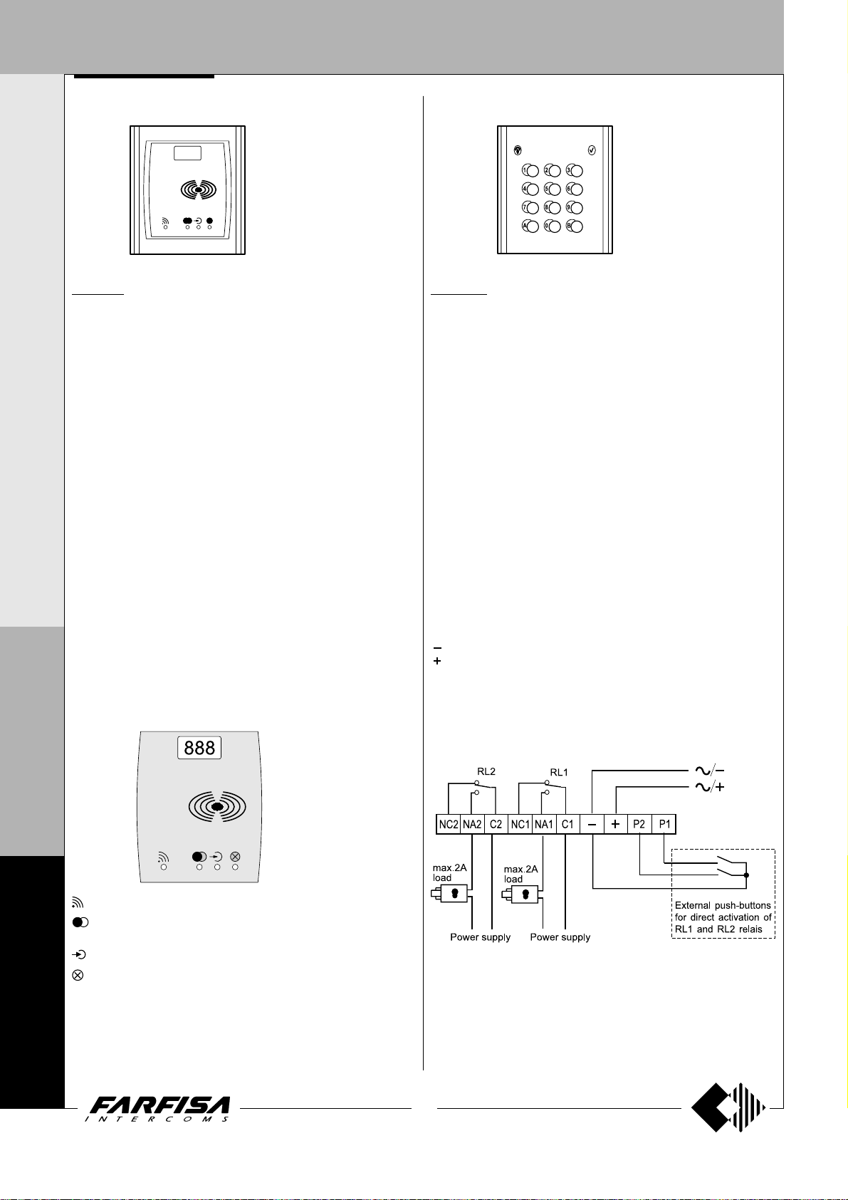
PROXIMITY READER MODULE
ACCESS CONTROL KEYPAD MODULE
FP52PL.
This article allows for the activation of 2 relays by means of keytags or
electronic ISO cards based on transponder technology.
Programmable activation time from 1 to 63 seconds for every relay. 4
user cards and 1 master card supplied with the product. Acoustic and
visual control signals and 3-digit display to view numbers and codes
during setup and operation.
Technical data
Power supply 12Vac/dc ±10%
Standby current 0.1A
Maximum current consumption 0.25A
Contact ratings 24Vac - 2A
Max. number of cards 490
Max. number of Master cards 10
Number of relays 2
Relay time 1 to 63 sec.
Minimum recognition distance 3 cm
Maximum recognition time 1 sec.
Operating temperature 0° ÷ +40°C
Maximum permitted humidity 85% RH
Terminals
+/A positive or alternate current input
-/A ground or alternate current input
PB door open button
NC2 normally closed contact of relay 2
NA2 normally open contact of relay 2
P
C2 common terminal of relay 2
NC1 normally closed contact of relay 1
R
NA1 normally open contact of relay 1
O
C1 common terminal of relay 1
F
FC 52PL.
Electronic keypad with 12 keys and 2 relays for lock release and access
control of door stations.
12 programmable access codes for each relay. Programmable door
opening time from 1 up 99 sec. for each relay (or bistable operation of
relay). Acoustic and visual confirmation for entered keys, accepted
programming and for wrong codes.
Technical data
Power supply: 12Vac/dc ±10%
Standby current: 0.06A
Max. current consumption: 0.15A
Contact ratings: 12Vac - 2A
Numbers of codes for relay 1: 12 + direct activation
Numbers of codes for relay 2: 12 + direct activation
Activation time for each relay: from 1 to 99 seconds (or bistable)
Operating temperature: 0° ÷ +40°C
Maximum permissible humidity: 85% RH
Terminals
NC2 normally closed contact of relay 2
NA2 normally open contact of relay 2
C2 common contact of relay 2
NC1 normally closed contact of relay 1
NC1 normally open contact of relay 1
C1 common contact of relay 1
ground or alternating voltage input
positive or alternating voltage input
P2 enable of relay 2; if the contacts are temporarily closed relay 2 is
activated for the programmed time
P1 enable of relay 1; if the contacts are temporarily closed relay 1 is
activated for the programmed time
I
L
O
F
N
4
0
0
0
Card recognition LED. It turns ON during card recognition.
Relay activation LED. It indicates relay deactivation (red) or activation
(green).
Program LED. It turns ON during system programming.
Card cancellation and system setup LED. It turns ON during Master
or user card cancellation and system setup.
8
(MT10 - Gb2010)
Page 11
DOOR ST A TIONS
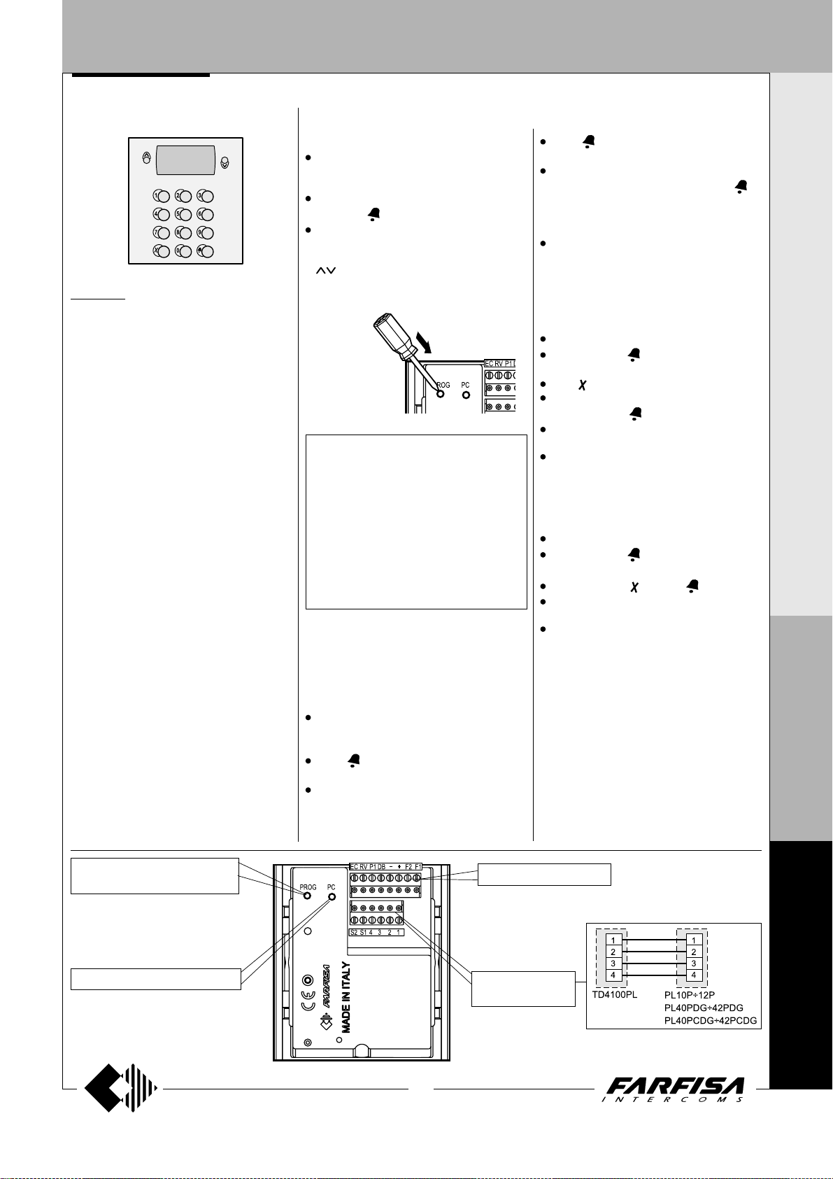
DIGITAL PUSH-BUTTON PANEL
DIGIT AL PUSH-BUTT ON P ANEL
TD4100PL. Push-button panel with 14 steel
buttons and alphanumerical LCD. Used to dial
and send calls over FN4000 digital line.
Technical features
Power supply 12Vdc ± 1
Operating current 0.05A
Maximum absorption 0.12A
Door-opening time 3 / 6 sec.
LCD 2 lines x 16 characters
Number of calls (hypothetical) 9999
Memory 250 names
Dimensions 1 module
Operating temperature 0°÷+40°C
Maximum humidity acceptable 90% RH
Terminals
F1 audio from internal stations
F2 audio to internal stations
- ground
+ +12Vdc power supply input
DB serial data bus
P1 direct call button input to the exchanger or
to an user
EC output command for a analog exchanger
(grounded contact upon call and during
conversation)
RV video-OFF command (grounded contact
upon call and during conversation)
S1-S2 door opener command (normally open
contacts of relay)
Terminal board for door speaker connection
1 audio receiver
2 audio transmitter
3 +12Vdc (0.2A) power supply output
4 audio ground
PROGRAMMING
Before programming you must:
Press the button PROG on the back of the
push-button panel using a small screwdriver;
the displays shows “
Dial the programming code (
and press
Once you have programmed each code,
press the button PROG again; the display
FARFISA / dial the number or press
shows “
” or the text set during the programming
phase (see “Personalisation of display
initial text”).
Table 1
Programming codes
00 Entry of codes for door lock
01 Entry-modification-deletion of names
02 Language selection
03 System programming
04 Entry of display initial text
05 Loading names from PC
06 Ordering names
10 Address door station (PE)
11 Address button P1
Entry of codes for door lock
Enter the programming mode and insert code
00 to access the “entry of codes for door
lock” mode; the display shows "
".
0 /
Dial the first opening code on the keypad, for
example 7890; the display shows
WORD 0 / 7890”.
Press ; the display shows
1 / ”.
Dial the second opening code on the keypad,
for example 1234; the display shows
“PASSWORD 1 / 1234”.
Programming / type:
see table 1
to confirm.
(code 00)
PASSWORD
“PASS-
“PASSWORD
Press ; the display shows
2 / ”.
Repeat the operations to insert max. 16
“.
codes; when you press the button
)
confirm the sixteenth code (PASSWORD
15) the display shows
“.
Continue by entering the code of a new
programming function or press the button
PROG to exit.
Modifying a code
To change the previously saved code you must
enter the programming mode and then:
select the programming code 00;
press the button until the code you want to
modify is displayed;
press to go to the code you want to modify;
enter the new code on the keyboard and then
press the button
repeat the operation for all the codes you
want to modify;
press the button PROG to exit the program-
ming mode.
Deleting a code
To delete the previously saved code you must
enter the programming mode and then:
select the programming code 00;
press the button until the code you want to
delete is displayed;
press the button and then ;
repeat the operation for all the codes you
want to modify;
press the button PROG to exit the program-
ming mode.
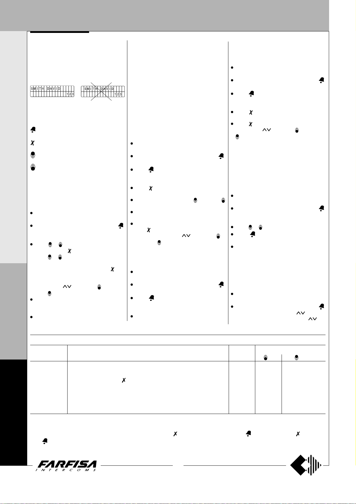
Entry / modification / deletion of names
(code 01)
The digital keyboard TD4100PL has an
alphanumerical display with 32 characters that
displays the user name and extension number
(28 characters are used for user name and the
last 4 characters on bottom right are used for
extension number). To save them, you must
follow the procedure illustrated below. The name
must be entered starting from the first character
on top left and the last digit of the extension
number must be entered in the last position on
;
“PASSWORD
“Programming / type:
I N T E R C O M S Y S T E M S * V I D E O I N T E R C O M S Y S T E M S
to
P
R
O
F
I
L
O
PROG
key of programming
jack for the connection to the PC
9
(MT10 - Gb2010)
to the installation
to the door speaker
and electric door lock
F
N
4
0
0
0
Page 12
DOOR ST A TIONS
DIGITAL PUSH-BUTTON PANEL
I N T E R C O M S Y S T E M S * V I D E O I N T E R C O M S Y S T E M S
bottom right, otherwise the number will not be
saved (see “deletion of names”).
After you have entered all the names, the system
will automatically arrange them in alphabetical
order.
Example
YES NO
Function of buttons when entering or
modifying a name
Hold this button pressed to scroll the list of
existing names
Hold this button pressed to move the cursor
to the name characters
Hold this button pressed to scroll down the
list of characters
Hold this button pressed to scroll up the list
of characters
When searching for characters, the display
shows uppercase letters, low-case letters,
numbers, special characters and space in a
sequence.
Entry of names
Press the button PROG to enter the programming mode.
Enter the code 01 and press the button ;
the display shows the first name. The display
is empty if no codes are programmed.
Press or to select the character for the
to go to the second cell;
shows “STORE
”; press to confirm;
P
R
O
F
I
first cell; press
press
or to select the character for the
second cell; continue until you have entered
the complete name with code. Press
you have entered the number in the last cell
on bottom right; the display
USER / YES NO
to modify the name.
press
If confirmed, the display shows the second
name. The display is empty if no names are
programmed.
Press the button PROG again to confirm the
after
last name to insert. The display shows “
and an automatic status bar. Normal
ing”
operation is restored after a few seconds
and the display shows the initial text (see
“
Operation”).
Notes. Once you have entered 250 names the
display shows “
bar. After a few seconds the display shows
“Programming / type:
with programming or press the button PROG to
exit.
You can enter 2 or more names with the same
call number (i.e. different family names in the
same apartment).
Modification or correction of names
Press the button PROG to enter the programming mode.
Enter the code 01 and press the button ;
the display shows the first name.
Press to search for the name you want to
modify (hold the button pressed for quick
searching).
Press to go to the character you want to
modify.
Select the character with (forward)
(backward).
Repeat the operation until you have
completed the name modification.
Once you have completed the modification,
hold
“STORE USER / YES NO”.
confirm or
Enter a space to delete a letter.
Addition of 1 or more names to the list
To add a new name to the existing list you must:
press the button PROG to enter the program-
ming mode;
enter the code 01 and press the button ;
the display shows the first name;
press to scroll the list (hold the button
pressed for quick searching); the display is
empty after the last name;
to enter a new name follow the operations
described in “Entry of names”. If confirmed,
waiting”
and an automatic status
“ and you can continue
pressed until the display shows
to modify the name again.
wait-
Press to
the name is placed in the list in alphabetical
order.
Deletion of names
Press the button PROG to enter the programming mode.
Enter the code 01 and press the button ;
the display shows the first name.
Press to search for the name you want to
delete (hold the button pressed for quick
searching).
Press to go to the last cell (bottom right);
enter a space to delete the existing number.
Press again; the display shows
USER / YES
to go back to the name.
The next name is displayed after you have
deleted the name.
Language selection
You can choose the language from 8 different
options (Italian, English, French, German,
Spanish, Portuguese, Turkish and Polish) in
operation mode.
To select the language:
press the button PROG to enter the program-
ming mode;
enter the code 02 and press the button ;
the display shows
programming or the programmed language;
press or to select the language.
press to confirm; the display shows
“Programming / type: “
continue by entering the code of a new programming function or press the button PROG
to exit.
System programming
You can change or activate the functions of the
push-button panel
For programming you must:
press the button PROG to enter the program-
ming mode;
enter the code 03 and press the button ;
the display shows
of first programming or
NO”
Press to confirm or
(code 02)
“Italiano”
(code 03)
(see table 2).
“bit 0 = 0 / 0 1”
“bit 0 = 1 / 0 1”
L
Table 2 - System programming codes
O
Programming Function description Default Value entered with buttons
code settings
(code 03)
= 0 = 1
“DELETE
in case of first
;
in case
if
F
N
4
0
0
0
bit 0 door lock activation time 3 sec. 3 sec. 6 seconds
bit 1 activation upon call from internal station
bit 2 door lock activation with
bit 3 not used - - -
bit 4 call numbers displayed with initial letter
bit 5 activation of personalised initial screen
bit 6 deactivation of FARFISA and activation of personalised text NO NO YES
bit 7 deactivation of tone generator NO NO YES
(1)
This function allows the internal stations to press the door lock button, start a conversation with the external station (in case of more external
stations in parallel the function must be activated on one external station only) and activate the door lock by pressing the button again.
(2)
This functions allows for quicker door lock activation by pressing rather than dialling the code 00+ . For example: press + password
+
.
(3)
You can alternate
“FARFISA”
with the personalised text (see “Personalisation of text to be shown on the display”).
(2)
(1)
(see relative paragraph)
(3)
NO NO YES
NO NO YES
NO NO YES
NO NO YES
10
(MT10 - Gb2010)
Page 13
DOOR ST A TIONS
DIGITAL PUSH-BUTTON PANEL
changed in the previous programming;
press to select 0 or to select 1;
press to confirm and go to the next code
(see code table with descriptions);
once you have confirmed the value of the last
code (bit 7), the display shows
“;
/ type:
continue by entering the code of a new programming function or press the button PROG
to exit.
- Enabling of alphanumerical calling mode
(bit 4)
If the installation is divided into several blocks,
it could be useful call each block with a letter
instead of a number (e.g. block "A", block "B",
etc.). If you program such a operating mode the
number of thousands in the user code is displayed as a letter and not as a number (1=A,
2=B, 3=C, 4=D, 5=E, 6=F, 7=G, 8=H, 9=I, 0=J).
Please consider that it is only a question of
displaying because the codes send to the users are always numerical codes, really the user
identified by the code "B001" is stored as user
2001 and this code must be programmed on its
intercom, videointercom or floor decoding
module. It is still important to note that if an
alphanumeric code, with less than 4 digit, is
entered on the keypad, the system automatically fills the empty numbers with zeros, for
instance entering only the code "E" the display
shows the code "E000" and the system transmits the code 5000. In the same way if the code
"E2" is entered the display shows "E002" and
the system transmits the code 5002, therefore
the user you want to be identified by the code
"E002" must be programmed as user 5002.
Personalisation of display initial text
“Programming
(code
04)
You can modify the text shown on the display
during normal operation or idle state. For
visualization you must set bit 4 or bit 5 with value
“1” (see “system programming”).
To insert a personalized text:
press the button PROG to enter the program-
ming mode;
enter the code 04 and press the button ;
the display shows
programming, or the text you want to replace;
for information on how to enter the characters
see “entry of names”;
press to confirm; the display shows
“Programming / type:
continue by entering the code of a new programming function or press the button PROG
to exit.
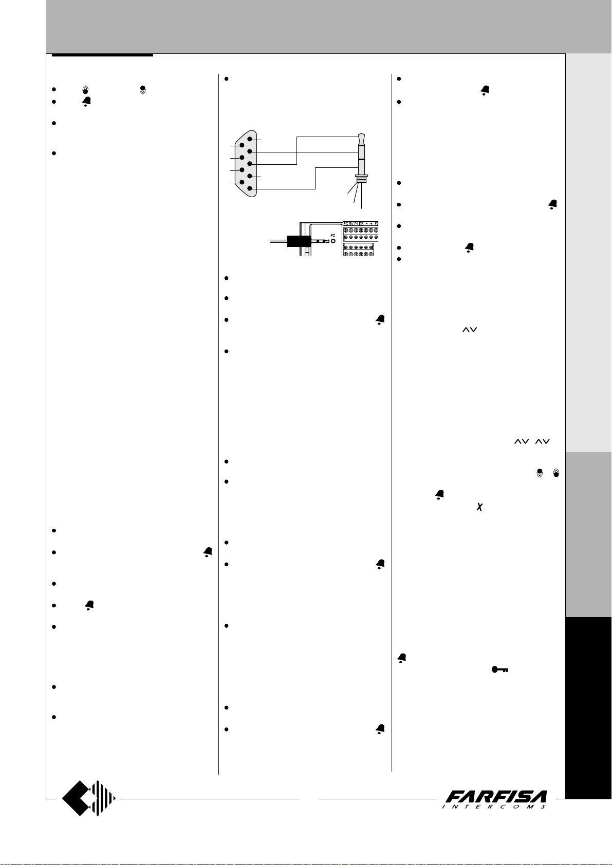
Loading names from PC
You can load names directly from your PC.
Load the names on the PC using a dedicated
software application (
).
demand
Turn off the push-button panel and the PC.
“FARNET
“, in case of first
“;
(code 05)
software supplied on
Connect the PC serial port to the stereo jack
on the back of the push-button panel with a
cable as shown in the figure.
PC serial port
6
7
8
9
1
2
3
4
5
TD4100PL
Stereo jack
Ø = 2.5mm
5
2
3
3
2
5
to PC
Turn on the PC and then the push-button
panel.
Press the button PROG to enter the programming mode.
Enter the code 05 and press the button ;
the display shows
progress....0”.
Download the names from the PC within 15
seconds; the display shows
PC / in progress....1”,
progress....2”
names.
At the end of download the push-button
deletes the existing names. The first line of
the display shows
line shows a status bar to show the progress
of the deletion operation. At the end the
display shows
Turn off the push-button panel and then the
PC.
Disconnect the cable from the PC and the
push-button panel.
Ordering names
You can list the names in alphabetical order
(from A to Z).
Press the button PROG to enter the programming mode.
Enter the code 06 and press the button ;
the first line of the display shows
the second line shows a status bar; at the end
of the operation the push-button panel returns automatically to the programming mode
(the display shows
Continue by entering the code of a new programming function or press the button PROG
to exit.
“TD4100PL ---- PC / in
“TD4100PL ----
“
TD4100PL ---- PC / in
and then the downloaded
“waiting”
“Programming / type: “
and the second
.
(code 06)
“waiting”
“Programming / type: “
and
Inserting the external door station address
code 10
PE (
You can code the external door station address
with codes from 231 to 250.
Press the button PROG to enter the programming mode.
Enter the code 10 and press the button ;
the display shows "
)
ADDRESS PE
".
Dial the coding number for the door station
and press the button
Continue by entering the code of a new pro-
gramming function or press the button PROG
to exit.
to confirm.
Inserting the button address P1
To save an extension number and call it directly
from a button connected between terminals
P1/P1:
press the button PROG to enter the program-
ming mode;
enter the code 11 and press the button ;
the display shows "
dial the extension number. Extensions must
be coded with numbers from 001 to 200;
press the button to confirm;
continue by entering the code of a new pro-
gramming function or press the button PROG
to exit.
ADDRESS P1
Return to operation mode
Press the button PROG at the end of program-
ming; the display shows “
number or press
entered during programming (see
"Personalisation of display initial text”).
FARFISA / dial the
” or the text you have
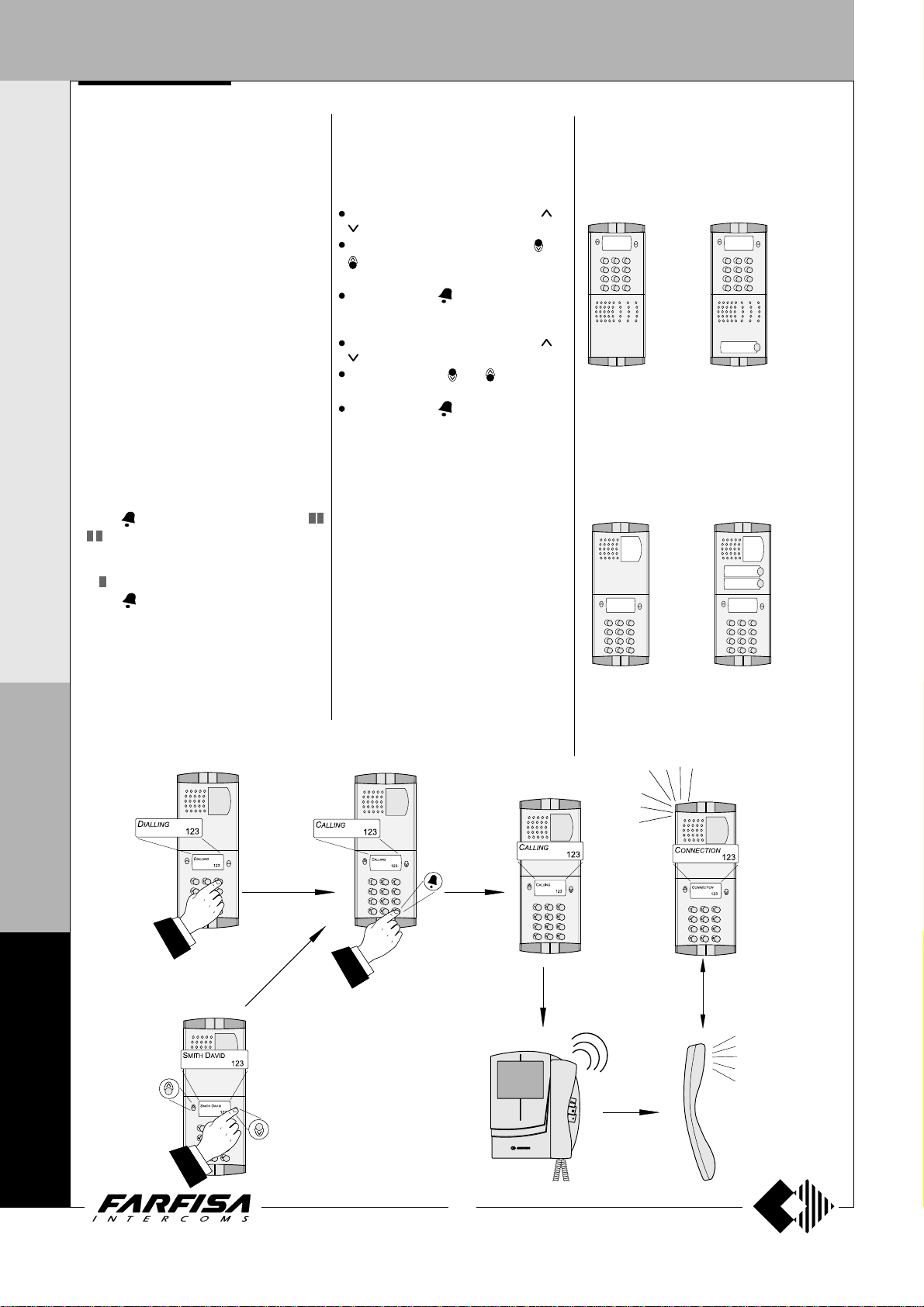
OPERATION
Check that all connections are correct. Connect
the power supply unit to the mains; the displays
shows for 3 seconds "
the software version of the push-button panel
and “
Dial the number or press
alternate mode).
Dial the user number or select the internal
station from the names in the list (press
to search), to verify its exactness on the display
and press
In case of error press
the call) and dial the correct to number.
If the user is busy or if the user code does not
exist the display shows “
If the user exists you hear the ringing tone and
the display shows “
intercom rings for about 25 seconds.
The called user picks up the handset to interrupt
the call and enables the conversation with the
external station for 60 seconds. The display
).
shows “
The text on the display starts flashing 10 seconds
before conversation ends. To continue
conversation for additional 60 seconds press
again.
Press the intercom button (
door lock. Door lock activation time is 3 seconds
(or 6 seconds if properly programmed).
Replace the handset to restore the idle state.
Numbers that are not sent or deleted go off after
25 seconds.
In installations with 2 or more digital push-
button panels, when a call is made from one
push-button panel, the other push-button panels
to make the call.
connection /---- ”.
FARFISA
ringing / ----”
", followed by
(only before sending
busy / ”
for 3 seconds.
; the called
) to release the
(code 11)
";
( in
or
I N T E R C O M S Y S T E M S * V I D E O I N T E R C O M S Y S T E M S
P
R
O
F
I
L
O
F
N
4
0
0
11
(MT10 - Gb2010)
0
Page 14
DOOR ST A TIONS
I N T E R C O M S Y S T E M S * V I D E O I N T E R C O M S Y S T E M S
are deactivated and their display shows
/ ”.
Wait until the line is free to make the call.
In installations with doorkeeper exchanger
in “Day” mode without direct dialling function,
all calls are sent to the exchanger.
Once the call is received, the operator can put
the push-button panel on hold and call the internal
station; the push-button display shows
on / ”.
If the operator connects the internal station with
the push-button panel, the display returns to the
conversation status. The number displayed on
the push-button panel is the number of the
internal station called by the operator and it
may not correspond to the called number
because of the call transfer function.
Door lock release
The door lock, even if in busy state, can be
released from the push-button panel by dialling
one of the 16 four digit personal access codes
you have stored.
Door lock activation
- Dial 00
- Press
- Dial the personal access code within 10
seconds; each digit is visualised with * instead
of
- Press
the confirmation tone and the push-button
panel returns to the current system operation
mode (free or busy).
; the display shows “
“
.
to release the door lock; you hear
Password
“busy
“hold-
DISPLAY SETTINGS
You can adjust the display contrast and
background color with the buttons of the
push-button panel.
Contrast
dial 0090; the display shows “
” with a state bar;
within 5 seconds press the buttons and
to increase or decrease the display
contrast;
press the button to save.
Background color
dial 0091; the display shows “
” with a state bar;
press the buttons and to select the
color;
press the button to save.
Tone t able. See page 29.
/
press or
press or
DIGITAL PUSH-BUTTON PANEL
Composition PROFILO digital push-button
panel
Audio composition
traditional
Composed of:
1 TD4100PL
1 PL10P
1 PL72
1 PL82 *
Audio-video composition
traditional
with push-button for the direct
call of an user
Composed of:
1 TD4100PL
1 PL11P
1 PL72
1 PL82 *
with push-button for the direct
call of an user
P
R
O
F
I
L
O
F
N
4
0
"Dialling"
or “Search”
Composed of:
1 TD4100PL
1 PL40PCDG
1 PL72
1 PL82 *
* optional
Composed of:
1 TD4100PL
1 PL42PCDG
1 PL72
1 PL82 *
0
0
12
(MT10 - Gb2010)
Page 15

DOOR ST A TIONS
PUSH-BUTTON PANEL WITH DIGITAL ENCODER
DIGITAL ENCODERS
CD4134PL. Encoding module with front plate
and four aluminium buttons. Complete with nameholders with transparent screen green backlighting, breaking resistant.
Used to send calls over FN4000 digital line.
CD4138PL. Same as the previous, but with 8
call buttons on two rows.
Technical features
Power supply: 12Vdc ± 1
Operating current: 0.1A
Maximum number of users: 63
Door-opening time: 3 seconds
Dimensions: 1 module
Operating temperature: 0° ÷ +40°C
Maximum permissible humidity: 90% RH
Terminals
F1 audio from internal stations
F2 audio to internal stations
- general ground
+ +12Vdc power input
DB serial data bus
L+ +12Vdc output for LED busy
EC command for an analog exchanger (grounded
contact upon call and during conversation)
RV video-OFF command (grounded contact upon
call and during conversation)
S1-S2 door opener command (normally open
contacts of relay)
Terminal board for door speaker connection
1 audio receiver
2 audio transmitter
3 +12Vdc (0.2A) power output
4 audio ground
P1- P2 call push-buttons *
* To be connected only if included in the pushbutton panel composition.
Programming
Following programming can be made in
digital encoders:
-starting user’s address of buttons
-user’s address related to the first button
-operating mode
Programming of starting user’s address of
buttons and user’s address related to
the first button fix the user’s address which
is called by pressing the first button; next
buttons will get the 3 sequential values. In
case of use of the module CD4138PL it is
possible to set also the user’s address called
by the first button of the second column and
consequently the next three.
Programming of operating mode gives the
possibility to change the activation time of
the relay (terminals S1-S2) and to enable the
automatic connection of the internal station
to the external station simply by pressing the
button “lock release” on the internal station;
ex factory the automatic connection is disabled while the activation time of relay is set
to 3 seconds.
Factory settings
Ex factory products are set as follows:
- starting user’s address of buttons = 0 (sending addresses from 1 to 63);
- user’s address related to the first button =
4 and, only for the CD4138PL, user’s address related to the first button of the left
column = 8; since buttons of digital encoder
CD4134PL, starting from the top, will call
users with users’ addresses 4,5,6 and 7
(right side column); while buttons of digital
encoder CD4138PL will call users with
users’ addresses 4,5,6 and 7 (right side
column) and 8,9,10 and 11 (left side column);
- operating mode of the digital encoder with
factory settings (activation time of relay = 3
seconds; no automatic connection between internal stations and external station.
In general this is the setting for the most frequent
installations; it is necessary to change
parameters in the following cases:
- installations with more than 63 users (sec-
ond encoder must be programmed with
starting user’s address of buttons equal or
higher than 63).
- digital encoder together with digital ex-
changer in installations with more blocks. In
this case it is mandatory that the programming of digital encoder and digital exchanger
are compatible.
Example
of one block is programmed with users’ addresses from 100 to 163 (enabled users’
addresses from 101 to 163), the digital encoder of the entrance of another block must
be programmed with different users’ addresses for example from 200 to 263 (en-
: the digital encoder of the entrance
I N T E R C O M S Y S T E M S * V I D E O I N T E R C O M S Y S T E M S
P
R
O
F
I
L
O
Terminal board of installation
to the PL10P, PL11P, PL12P door
speakers or PL40PCDG, PL42PCDG
cameras
13
(MT10 - Gb2010)
to JP1 of the first push-button module
to the installation
F
N
4
0
0
0
Page 16
DOOR ST A TIONS
I N T E R C O M S Y S T E M S * V I D E O I N T E R C O M S Y S T E M S
abled users’ addresses from 201 to 263),
etc.;
- installations where a digital doorkeeper exchanger is present and requirement to show
on its display users’ addresses according to
the floor of the building where the apartment
is located (e.g. first floor users’ addresses
111, 112, 113....etc; second floor users’ ad-
dresses 121,122,123...etc).
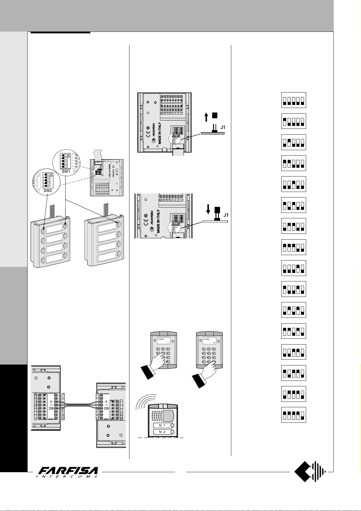
User’s address related to the first button
To program the user’s address related to the
first button it is sufficient to set micro-switches
SW1 and SW2 (the last present only on the
CD4138PL) located on the back of the digital
encoder. Table 1 shows how to set microswitches SW to set the requested address.
st
1
right side
button
left side
button
st
1
CD4138PL
CD4134PL
P
Programming of starting user’s address
R
of buttons and operating modes
To program the starting user’s address of
O
buttons and the operating modes it is necessary
F
that the digital encoder is connected on the
same riser on which it is even connected one
I
digital push-button panel TD4100PL or digital
doorkeeper exchanger PDX4000; In the case
L
this is not true it is possible to connect
temporarily, just for the time of programming,
O
one of the two equipments joining only terminals
+, - and DB.
TD4100PL
F
N
4
PUSH-BUTTON PANEL WITH DIGITAL ENCODER
Entering programming mode
To program the starting user’s address of
buttons and the operating modes it is necessary
to enter in the programming mode just pullingout jumper J1 in order to free the two poles;
digital encoder generates an intermitting waiting
tone.
Exit the programming mode
To exit programming mode insert again jumper
J1 in order to short-circuit the two poles.
Programming starting user’s address
- Enter the programming mode as described
in the specific paragraph.
- Dial on the keypad of TD4100PL or PDX4000
the address you wish to program and send
enter; an acknowledge tone will be heard.
- Make other programming or exit the
programming mode as described in the
specific paragraph.
In the case of sending more address only the
last one is stored.
Table 1.
Value to add to the starting user address
programmed on the digital encoder to obtain the address called by the first button.
Value Position of microto set switches SW
ON
0
4
8
12
16
20
24
28
32
36
40
44
48
52
56
60
12345
ON
12345
ON
12345
ON
12345
ON
12345
ON
12345
ON
12345
ON
12345
ON
12345
ON
12345
ON
12345
ON
12345
ON
12345
ON
12345
ON
12345
ON
12345
0
0
0
CD4134PL
CD4138PL
14
(MT10 - Gb2010)
Page 17
DOOR ST A TIONS
Important notes.
Setting all the micro-switches of SW2 in
OFF position (all the triggers set down; code
0) the system will not send the user’s address
related to the first button (being 0). Besides,
if are present buttons connected to P1 and
P2 they will have the same user’s address of
nd
2
and 3rd button of the digital encoder.
Some examples of programming
st
J1 SW 1
0+ 4 4 1 ÷ 63
0+ 12 12 1 ÷ 63
0+ 56 56 1 ÷ 63
15 + 4 19 16 ÷ 78
15 + 12 27 16 ÷ 78
15 + 56 71 16 ÷ 78
32 + 4 36 33 ÷ 96
100 + 0 100 101 ÷ 163
100 + 32 132 101 ÷ 163
150 + 36 186 151 ÷ 213
699 + 4 703 700 ÷ 762
micro-switching settings (see table 1)
address to send to the encoder during the programming phase
Programming of the operating modes
- Enter the programming mode as described in the specific
paragraph.
- Dial on the keypad of TD4100PL or PDX4000 the code you wish
to program (see table 2) and press button “enter”; an acknowledge
tone will be heard.
- Exit the programming mode as described in the specific paragraph.
In the case of sending more codes only the last one is stored.
button (N4) range of addresses
users’ addresses which can be managed by the encoder
user’s address related to the first button from the top (N.4)
PUSH-BUTTON PANEL WITH DIGITAL ENCODER
I N T E R C O M S Y S T E M S * V I D E O I N T E R C O M S Y S T E M S
by P1 and P2 has no relation with the address associated to the first button
of the digital encoder.
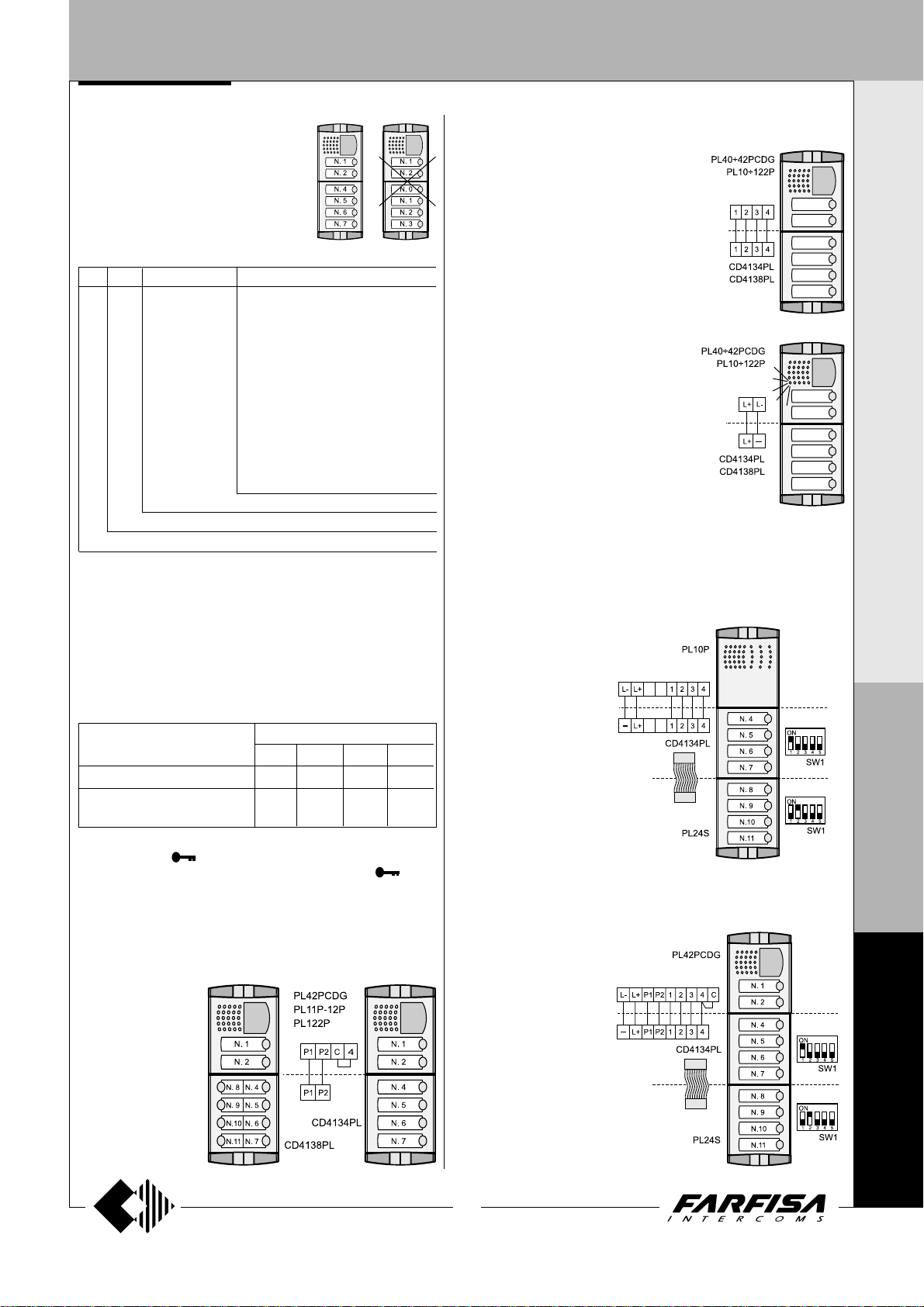
Audio Connection
The digital encoder should be connected to an
audio or video module by means of 4 wires
joined to the terminals 1, 2, 3 and 4.
Signalling of busy line.
If more than one entrance is present on the
same installation it would be advisable to have
a signalling of busy line when another external
station is already in communication. This can
be achieved, by the LED present on the audio
or audio/video module which will flash when
the line is busy, connecting their terminals L+
and L- to the terminals L+ and -present on the
digital encoder.
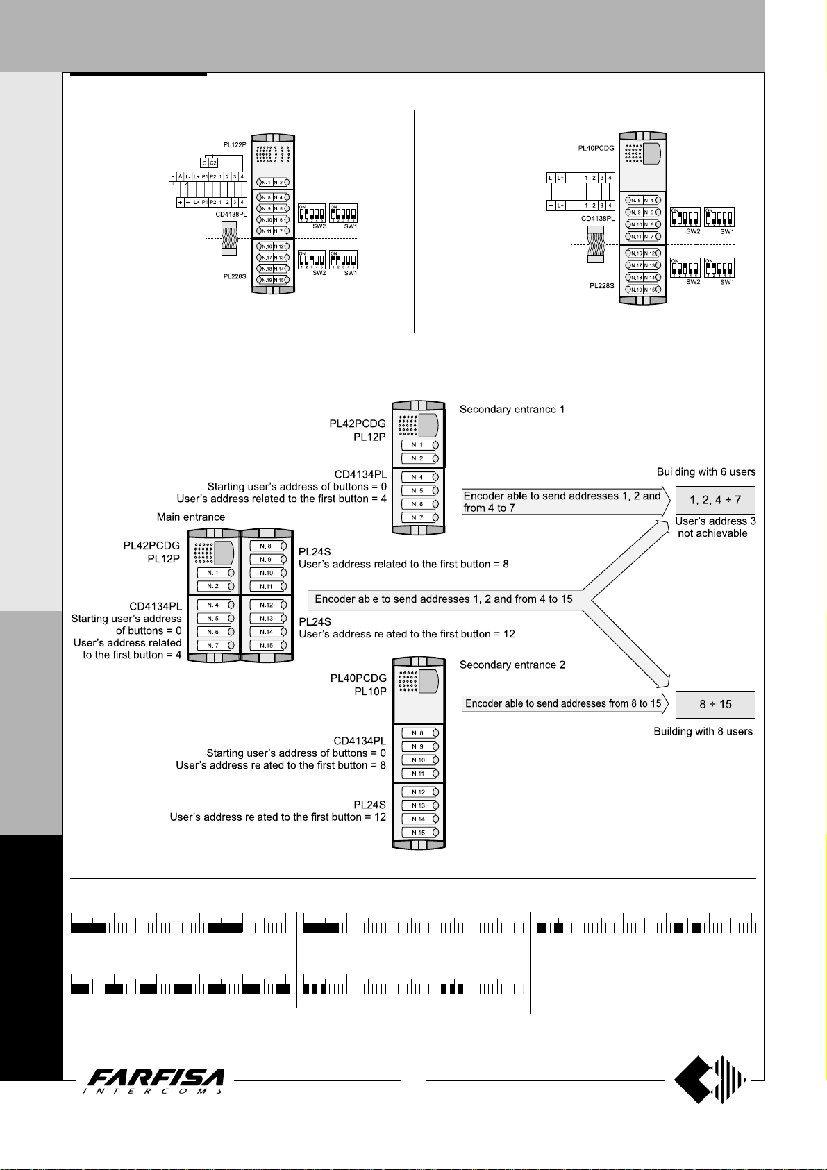
Example of composition of push-buttons with programming of the
user’s address associated to the first button and connections
between several modules
1) 8 call intercom push-button panel with PL10P, CD4134PL and
PL24S
Table 2. Operating modes
Operating mode Codes to dial
9990 9991 9994 9995
Timing of relay-ON 3 sec. 6 sec. 3 sec. 6 sec.
Enabling automatic connection of
door station from internal station*
* Enabling this function from any internal station it would be possible,
pressing button
to activate the lock release pressing again the button
Terminals P1 and P2
Connecting to the terminals P1 and P2 of the digital encoder the two
buttons of modules PL42PCDG or PL12P they will call users with the
two next addresses from the starting user’s address of buttons
programmed in the digital encoder.
Example
user’s address of
buttons programmed in
the digital encoder is
equal to 0, by pressing
the two buttons of
modules PL42PCDG
or PL12P they will call
respectively users
coded with the
addresses 1 and 2, the
user’s address called
: if the starting
, to communicate with the external station and
No No Yes Yes
.
2) 10 call videointercom push-button panel with PL42PDG,
CD4134PL and PL24S
Note. In this example the user’s address
3 is not achievable; do not code any user
with the address 3.
P
R
O
F
I
L
O
F
N
4
0
0
15
(MT10 - Gb2010)
0
Page 18
DOOR ST A TIONS
PUSH-BUTTON PANEL WITH DIGITAL ENCODER
I N T E R C O M S Y S T E M S * V I D E O I N T E R C O M S Y S T E M S
3) 18 call intercom push-button panel with PL122P, CD4138PL
and PL228S
Note. In this example the user’s address 3 is not achievable; do not code
any user with the address 3.
5) Example of coding of an installation with one main entrance and two secondary entrances (block division)
4) 16 call videointercom push-button panel with PL40PDG,
CD4138PL and PL228S
P
R
O
F
I
L
O
F
Tone table
N
012345
Free-
Indicates that the line is free
4
012345
0
-
Indicates that the called user is busy
Busy
0
012345
End of conversation -
sation ends
012345
Confirmation -
executed
10 seconds before conver-
Indicates that programming was
012345
Programming and waiting -
Indicates the programming mode or the waiting status of
the external user
0
16
(MT10 - Gb2010)
Page 19
DOOR ST A TIONS
PUSH-BUTTON PANEL WITH DIGITAL ENCODER
PUSH-BUTTON MODULES WITH INTEGRATED
ENCODING BOARD
1.push-button
2.push-button
3
.push-button 3. p.
4.push-button 4. p.
The button modules with integrated encoding board, thanks to the
connection to the encoder module CD4134PL÷CD4138PL, allow the
calls in digital systems.
fig.1
5. p.
6. p.
7. p.
8. p.
1. p.
2. p.
PL24S.
Module with front plate and four aluminium call buttons. Complete with
name holders with transparent screen green backlighting, resistant to
breaking and connection cable to the next module.
PL228S.
Same as the previous, but with 8 call buttons on two rows.
Terminals
A+ AC or DC power supply input for nameplate Led (13Vac/dc-80mA)
A- AC power supply or ground input for nameplate Led
Programming
The microswitches, present on the back of the PL24S and PL228S,
allow the digital encoder to recognize the code of the connected buttons,
consequently they must be programmed properly. The code set on the
microswitches (
associate to the 1
buttons on the module automatically are associated the next addresses.
The address of the Called User is obtained combining the address
associated to the First button of the module at which the push-button is
connected to and the Address associated to the Encoder according to
the following rule:
Called User Address (IUC) by pressing the buttons of the CD4134PL,
CD4138PL, PL24S or PL228S module = Address Associated to the
Encoder (IAC) + Number Associated with Button (NAP) of the
CD4134PL, CD4138PL, PL24S or PL228S module.
General rule: IUC = IAC + NAP
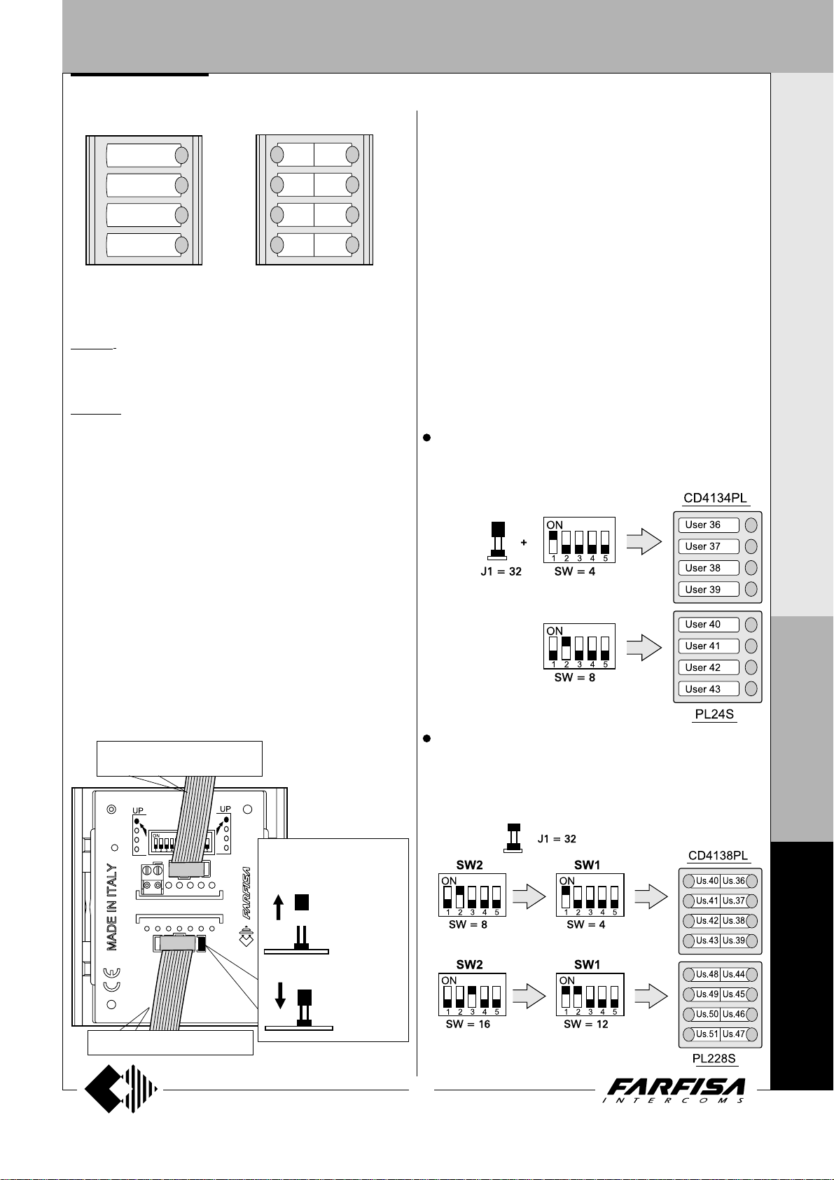
General rule applied to the first example below;
- if you press the first button from above of the PL24S:
the user with address 40 will be called.
Examples:
In the example the following codes have been set:
- Address associated to the encoder = 32
- Address associated to the first button of the encoder = 4
- Address associated to the first button of the module PL24S = 8
see tables on the page 18
st
push-button of the module (
40 (IUC) = 32 (IAC) + 8 (1
) determines the address
see fig.1
); the other push-
st
NAP)
I N T E R C O M S Y S T E M S * V I D E O I N T E R C O M S Y S T E M S
Installation and connections
- Connect the first push-button panel to the digital encoder module with
the cable supplied.
- Connect the second push-button module to the first one with the cable
supplied with the second module.
- Connect all modules in a sequence.
- Connect the two power supply wires of the name plate LED’s (13Vac)
to terminals A+/A- of the first push-button panel and remove jumper J1
only in this module.
Important notes
- Pay attention when program code 0 (address interval 0-3) because in
this case the first push-button from the top does not call any user. This
is due to the fact that the system does not recognize the address 0
(zero) as a valid address.
-to previous push-buttons module or digital encoder
- Selection of the power
JP1
JP2
supply of the name plate
Led
- power supply
with additional
transformer
Address of the 1st user of the module (IUC = 32+4 = 36)
The 3 following addresses of the module are 37, 38, 39
st
Address of the 1
The 3 following addresses of the module are 41, 42, 43
In the example the following codes have been set:
- Address associated to the encoder = 32
- Address associated to the 1
- Address associated to the 1
- Address associated to the 1
- Address associated to the 1
Address of the 1st user on right (IUC = 32+4 = 36)
Address of the 1
user of the module (IUC = 32+8 = 40)
st
button on right of the encoder = 4
st
button on left of the encoder = 8
st
button on right of the mod. PL228S = 12
st
button on left of the module PL228S = 16
st
user on left (IUC = 32+8 = 40)
P
R
O
F
I
L
O
F
N
-to next push-buttons module
- power supply
through previous push-buttons module
(MT10 - Gb2010)
Address of the 1
Address of the 1
17
st
user on right (IUC = 32+12 = 44)
st
user on left (IUC = 32+16 = 48)
4
0
0
0
Page 20
DOOR STATIONS
I N T E R C O M S Y S T E M S * V I D E O I N T E R C O M S Y S T E M S
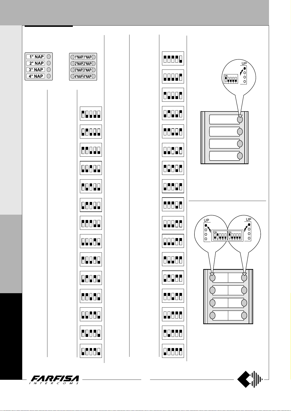
Example of order used to associate
numbers with buttons
PL24S
PL228S
SW1 SW1SW2
P
R
O
F
I
L
O
F
N
4
0
Code to
be set
4
8
12
16
20
24
28
32
36
40
44
48
52
56
Numbers associated with
buttons- NAP
st
NAP = 4
1
nd
2
NAP = 5
rd
3
NAP = 6
th
NAP = 7
4
1st NAP = 8
nd
NAP = 9
2
rd
3
NAP = 10
th
NAP = 11
4
st
NAP = 12
1
nd
NAP = 13
2
rd
3
NAP = 14
th
NAP = 15
4
st
1
NAP = 16
nd
NAP = 17
2
rd
3
NAP = 18
th
4
NAP = 19
st
1
NAP = 20
nd
NAP = 21
2
rd
3
NAP = 22
th
4
NAP = 23
st
1
NAP = 24
nd
2
NAP = 25
rd
3
NAP = 26
th
4
NAP = 27
st
NAP = 28
1
nd
2
NAP = 29
rd
3
NAP = 30
th
4
NAP = 31
st
1
NAP = 32
nd
2
NAP = 33
rd
3
NAP = 34
th
NAP = 35
4
st
1
NAP = 36
nd
2
NAP = 37
rd
3
NAP = 38
th
4
NAP = 39
st
NAP = 40
1
nd
2
NAP = 41
rd
3
NAP = 42
th
NAP = 43
4
st
NAP = 44
1
nd
NAP = 45
2
rd
NAP = 46
3
th
4
NAP = 47
st
1
NAP = 48
nd
2
NAP = 49
rd
NAP = 50
3
th
NAP = 51
4
st
NAP = 52
1
nd
NAP = 53
2
rd
3
NAP = 54
th
NAP = 55
4
st
1
NAP = 56
nd
NAP = 57
2
rd
NAP = 58
3
th
4
NAP = 59
Push-button microswitch SW
ON
12345
ON
12345
ON
12345
ON
12345
ON
12345
ON
12345
ON
12345
ON
12345
ON
12345
ON
12345
ON
12345
ON
12345
ON
12345
ON
12345
0
Code to
be set
60
64
68
72
76
80
84
88
92
96
100
104
108
112
116
120
124
PUSH-BUTTON PANEL WITH DIGITAL ENCODER
Numbers associated with
buttons- NAP
st
1
NAP = 60
nd
NAP = 61
2
rd
3
NAP = 62
th
4
NAP = 63
1st NAP = 64
nd
2
NAP = 65
rd
3
NAP = 66
th
NAP = 67
4
st
NAP = 68
1
nd
NAP = 69
2
rd
3
NAP = 70
th
4
NAP = 71
st
NAP = 72
1
nd
NAP = 73
2
rd
3
NAP = 74
th
4
NAP = 75
st
1
NAP = 76
nd
2
NAP = 77
rd
3
NAP = 78
th
4
NAP = 79
st
NAP = 80
1
nd
2
NAP = 81
rd
3
NAP = 82
th
NAP = 83
4
st
NAP = 84
1
nd
NAP = 85
2
rd
3
NAP = 86
th
4
NAP = 87
st
1
NAP = 88
nd
2
NAP = 89
rd
3
NAP = 90
th
4
NAP = 91
st
1
NAP = 92
nd
2
NAP = 93
rd
3
NAP = 94
th
4
NAP = 95
st
NAP = 96
1
nd
NAP = 97
2
rd
3
NAP = 98
th
NAP = 99
4
st
NAP = 100
1
nd
NAP = 101
2
rd
3
NAP = 102
th
4
NAP = 103
st
NAP = 104
1
nd
2
NAP = 105
rd
NAP = 106
3
th
4
NAP = 107
st
NAP = 108
1
nd
NAP = 109
2
rd
3
NAP = 110
th
4
NAP = 111
st
1
NAP = 112
nd
NAP = 113
2
rd
3
NAP = 114
th
4
NAP = 115
1st NAP = 116
nd
NAP = 117
2
rd
3
NAP = 118
th
NAP = 119
4
st
NAP = 120
1
nd
NAP = 121
2
rd
NAP = 122
3
th
NAP = 123
4
st
NAP = 124
1
nd
2
NAP = 125
rd
3
NAP = 126
th
4
NAP = 127
Push-button microswitch SW
ON
12345
ON
12345
ON
12345
ON
12345
ON
12345
ON
12345
ON
12345
ON
12345
ON
12345
ON
12345
ON
12345
ON
12345
ON
12345
ON
12345
ON
12345
ON
12345
ON
12345
First button indication and relevant
microswitch for coding
SW1
1. push-button
2. push-button
3. push-button
4. push-button
PL24S
SW1SW2
1.push5.push
2.push6.push
3.push7.push
4.push8.push
PL228S
0
18
(MT10 - Gb2010)
Page 21

DOOR STATIONS
DOOR STATIONS
Operation
Check that the connections of the system are
correct.
Connect the power supply unit to the mains to
start operation.
Press the button that corresponds to the desired user. The free tone indicates that the
call has been sent and the internal station
rings for about 25 seconds.
The called user picks up the handset (or
press
call and enable the external conversation for
60 seconds.
Both users hear the end tone 10 seconds
before the conversation ends. Press the call
button again to continue the conversation for
other 60 seconds.
The system returns to the idle state when the
user hangs up (or press for Echos series).
door station 1
for Echos series) to interrupt the
If no answer is received from the internal user
when the call button is pressed, a 25-second
wait is necessary before making other calls.
The door can only be opened while the conversation is in progress.
The busy indicator turns on when a conversation is in progress in case of systems with
more than one main entrance or systems
provided with the doorkeeper exchanger. Wait
until the indicator turns off before making a
call.
The external station hears the busy tone when
calling a user who is having a conversation
with a floor entrance or with a secondary
staircase entrance and the busy indicator turns
on for 5 seconds. Use the
the tone volume.
trimmer to adjust
INSTALLATION
PL42PCDG
CD4134PL
CD4138PL
I N T E R C O M S Y S T E M S * V I D E O I N T E R C O M S Y S T E M S
PL40PCDG
TD4100PL
door station 2
busy
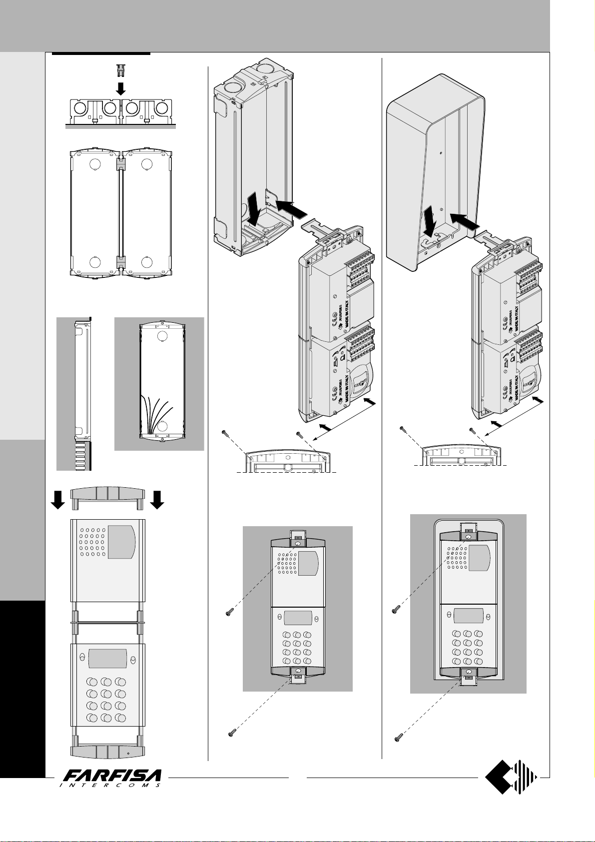
Place the push-button panel back box at a
height of about 1.65m
keeping the front edges flush-mounted and vertical to the finished plaster.
Position the camera in such a way that
sunlight or other direct or reflected light
sources with high intensity do not hit the
camera lens.
(5' 5")
from the floor
P
R
O
F
I
L
O
F
N
19
(MT10 - Gb2010)
Openings for cables.
4
0
0
0
Page 22
DOOR STATIONS
I N T E R C O M S Y S T E M S * V I D E O I N T E R C O M S Y S T E M S
Insertion of spacers between back boxes.
Spacers and cable bushing (not supplied
with the products) must be inserted before
brick work.
Fix lower part of the
frame to the back box
and make the electrical connections.
Rain shelter
Fix lower part of the
frame to the rain shelter
and make the electrical
connections.
P
R
O
F
I
L
O
F
N
4
0
0
Flush mounting and cables
placing.
Mounting
modules.
Fixing of the module frames on the upper side by
the 2 small screws included in the back boxes.
Fixing of frame to back box. Align
the frame before tightening the
screws.
Fixing of the module frames on the upper side
by the 2 small screws included in the rain
shelter.
Fixing of frame to rain shelter.
Align the frame before tightening
the screws.
0
20
(MT10 - Gb2010)
Page 23
DOOR STATIONS
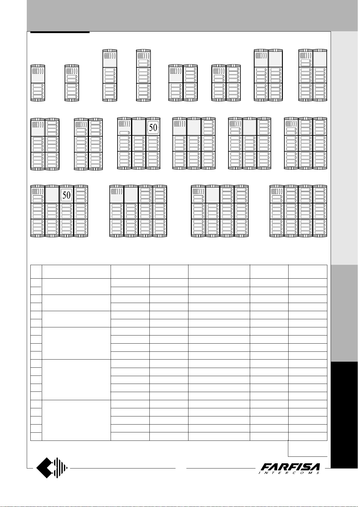
1 ROW PUSH-BUTTON PANEL Examples of installations in intercom systems
4 buttons 6 buttons
22 buttons20 buttons
8 buttons 12 buttons 14 buttons
10 buttons 18 buttons16 buttons
25 buttons 28 buttons
30 buttons
34 buttons
I N T E R C O M S Y S T E M S * V I D E O I N T E R C O M S Y S T E M S
38 buttons
Nr
calls
10
12
14
16
18
20
22
25
26
28
30
34
36
38
40
42
46
(**) Hood covers can be added, if necessary
4
6
8
and dimensions
100x253.5x19
(3 15/16" x 10" x 3/4")
100x365x19
(3 15/16" x 14 3/8" x 3/4")
200x253.5x19
(7 7/8" x 10" x 3/4")
200x365x19
(7 7/8" x 14 3/8" x 3/4")
300x365x19
(11 13/16" x 14 3/8" x 3/4")
400x365x19
(15 3/4" x 14 3/8" x 3/4")
Encoder moduleComposition
1 CD4134PL
1 CD4134PL
1 CD4134PL
1 CD4134PL
1 CD4134PL
1 CD4134PL
1 CD4134PL
1 CD4134PL
1 CD4134PL
1 CD4134PL
1 CD4134PL
1 CD4134PL
1 CD4134PL
1 CD4134PL
1 CD4134PL
1 CD4134PL
1 CD4134PL
1 CD4134PL
1 CD4134PL
1 CD2134PL
(see page 5)
42 buttons
46 buttons40 buttons
Composition board of INTERCOM push-button panels.
Speaker
module
1 PL10P
1 PL12P
1 PL10P
1 PL12P
1 PL10P
1 PL12P
1 PL10P
1 PL12P
1 PL10P
1 PL12P
1 PL11P
1 PL12P
1 PL10P
1 PL12P
1 PL12P
1 PL10P
1 PL12P
1 PL10P
1 PL12P
1 PL12P
Buttons, blank
or number modules (*)
-
-
1 PL24S
1 PL24S
2 PL24S
2 PL24S
3 PL24S
3 PL24S
4 PL24S
4 PL24S
5 PL24S
5 PL24S
6 PL24S
6 PL24S
7 PL24S
8 PL24S
8 PL24S
9 PL24S
9 PL24S
10 PL24S
-
-
-
-
-
-
1 PL20
1 PL20
-
-
2 PL20
2 PL20
1 PL20
1 PL20
-
2 PL20
2 PL20
1 PL20
1 PL20
-
(*) or PL50
Back boxes and
mod. frame
(**)
1 PL72
1 PL72
1 PL73
1 PL73
2 PL72
2 PL72
2 PL73
2 PL73
2 PL73
2 PL73
3 PL73
3 PL73
3 PL73
3 PL73
3 PL73
4 PL73
4 PL73
4 PL73
4 PL73
4 PL73
Rain
shelters
1 PL92
1 PL92
1 PL93
1 PL93
1 PL94
1 PL94
1 PL96
1 PL96
1 PL96
1 PL96
1 PL99
1 PL99
1 PL99
1 PL99
1 PL99
-
-
-
-
-
It replaces
PL72 or PL73
P
R
O
F
I
L
O
F
N
4
0
0
21
(MT10 - Gb2010)
0
Page 24
DOOR STATIONS
I N T E R C O M S Y S T E M S * V I D E O I N T E R C O M S Y S T E M S
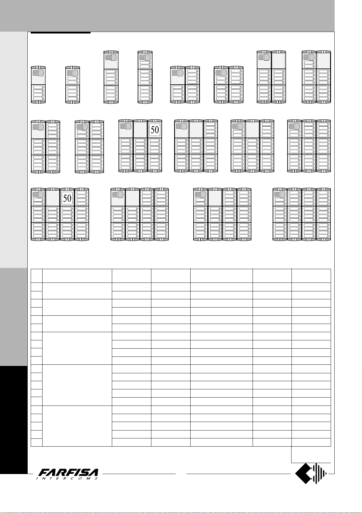
1 ROW PUSH-BUTTON PANEL Examples of installations in videointercom systems
4 buttons 6 buttons
22 buttons20 buttons
38 buttons
Nr
4
6
8
and dimensions
100x253.5x19
(3 15/16" x 10" x 3/4")
100x365x19
(3 15/16" x 14 3/8" x 3/4")
200x253.5x19
(7 7/8" x 10" x 3/4")
200x365x19
(7 7/8" x 14 3/8" x 3/4")
300x365x19
(11 13/16" x 14 3/8" x 3/4")
400x365x19
(15 3/4" x 14 3/8" x 3/4")
calls
P
R
O
10
F
12
I
14
16
L
18
O
20
22
24
26
F
28
30
N
34
36
38
4
40
42
0
46
0
(**) Hood covers can be added, if necessary
0
8 buttons 12 buttons 14 buttons
10 buttons 18 buttons16 buttons
24 buttons 28 buttons
42 buttons
Composition board of VIDEO INTERCOM push-button panels.
Encoder moduleComposition
1 CD4134PL
1 CD4134PL
1 CD4134PL
1 CD4134PL
1 CD4134PL
1 CD4134PL
1 CD4134PL
1 CD4134PL
1 CD4134PL
1 CD4134PL
1 CD4134PL
1 CD4134PL
1 CD4134PL
1 CD4134PL
1 CD4134PL
1 CD4134PL
1 CD4134PL
1 CD4134PL
1 CD4134PL
1 CD2134PL
(see page 5)
Camera and
speaker mod.
1 PL40PDG
1 PL42PDG
1 PL40PDG
1 PL42PDG
1 PL40PDG
1 PL42PDG
1 PL40PDG
1 PL42PDG
1 PL40PDG
1 PL42PDG
1 PL40PDG
1 PL42PDG
1 PL40PDG
1 PL42PDG
1 PL42PDG
1 PL40PDG
1 PL42PDG
1 PL40PDG
1 PL42PDG
1 PL42PDG
22
(MT10 - Gb2010)
Buttons, blank
or number modules (*)
-
-
1 PL24S
1 PL24S
2 PL24S
2 PL24S
3 PL24S
3 PL24S
4 PL24S
4 PL24S
5 PL24S
5 PL24S
6 PL24S
6 PL24S
7 PL24S
8 PL24S
8 PL24S
9 PL24S
9 PL24S
10 PL24S
(*) or PL50
-
-
-
-
-
-
1 PL20
1 PL20
-
-
2 PL20
2 PL20
1 PL20
1 PL20
-
2 PL20
2 PL20
1 PL20
1 PL20
-
30 buttons
Back boxes and
mod. frame
1 PL72
1 PL72
1 PL73
1 PL73
2 PL72
2 PL72
2 PL73
2 PL73
2 PL73
2 PL73
3 PL73
3 PL73
3 PL73
3 PL73
3 PL73
4 PL73
4 PL73
4 PL73
4 PL73
4 PL73
(**)
34 buttons
46 buttons40 buttons
Rain
shelters
1 PL92
1 PL92
1 PL93
1 PL93
1 PL94
1 PL94
1 PL96
1 PL96
1 PL96
1 PL96
1 PL99
1 PL99
1 PL99
1 PL99
1 PL99
-
-
-
-
-
It replaces
PL72 or PL73
Page 25
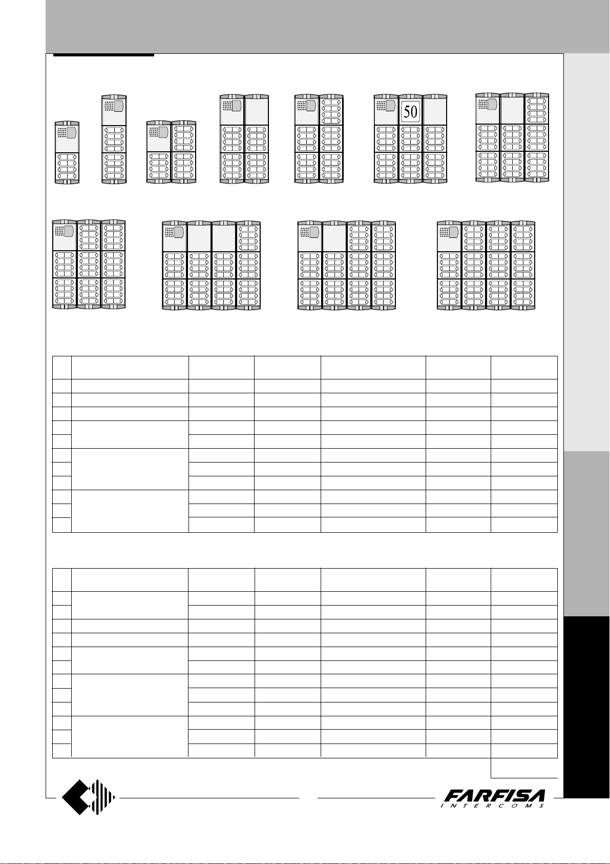
DOOR ST A TIONS
2 ROW PUSH-BUTTON PANEL
8 buttons
Nr
calls
8
16
24
32
40
48
56
64
72
80
88
16 buttons 24 buttons 32 buttons 40 buttons 48 buttons
64 buttons
and dimensions
100x253.5x19
100x365x19
200x253.5x19
(3 15/16" x 10" x 3/4")
(3 15/16" x 14 3/8" x 3/4")
(7 7/8" x 10" x 3/4")
200x365x19
(7 7/8" x 14 3/8" x 3/4")
300x365x19
(11 13/16" x 14 3/8" x 3/4")
400x365x19
(15 3/4" x 14 3/8" x 3/4")
Encoder moduleComposition
1 CD4138PL
1 CD4138PL
1 CD4138PL
1 CD4138PL
1 CD4138PL
1 CD4138PL
1 CD4138PL
1 CD4138PL
1 CD4138PL
1 CD4138PL
1 CD4138PL
Examples of installations in videointercom systems
56 buttons
80 buttons
88 buttons72 buttons
Composition board of VIDEO INTERCOM push-button panels.
Camera and
speaker mod.
1 PL40PCDG
1 PL40PCDG
1 PL40PCDG
1 PL40PCDG
1 PL40PCDG
1 PL40PCDG
1 PL40PCDG
1 PL40PCDG
1 PL40PCDG
1 PL40PCDG
1 PL40PCDG
Buttons, blank
or number modules (*)
1 PL228S
2 PL228S
3 PL228S
4 PL228S
5 PL228S
6 PL228S
7 PL228S
8 PL228S
9 PL228S
10 PL228S
1 PL20
2 PL20
1 PL20
2 PL20
1 PL20
Back boxes and
mod. frame
-
-
-
-
-
-
(**)
1 PL72
1 PL73
2 PL72
2 PL73
2 PL73
3 PL73
3 PL73
3 PL73
4 PL73
4 PL73
4 PL73
Rain
shelters
1 PL92
1 PL93
1 PL94
1 PL96
1 PL96
1 PL99
1 PL99
1 PL99
-
-
-
I N T E R C O M S Y S T E M S * V I D E O I N T E R C O M S Y S T E M S
P
R
O
F
Nr
calls
8
10
18
26
34
42
50
58
66
74
82
90
and dimensions
Encoder moduleComposition
100x253.5x19
100x365x19
200x253.5x19
(3 15/16" x 10" x 3/4")
(3 15/16" x 14 3/8" x 3/4")
(7 7/8" x 10" x 3/4")
200x365x19
(7 7/8" x 14 3/8" x 3/4")
300x365x19
(11 13/16" x 14 3/8" x 3/4")
400x365x19
(15 3/4" x 14 3/8" x 3/4")
(**) Hood covers can be added, if necessary
1 CD4138PL
1 CD4138PL
1 CD4138PL
1 CD4138PL
1 CD4138PL
1 CD4138PL
1 CD4138PL
1 CD4138PL
1 CD4138PL
1 CD4138PL
1 CD4138PL
1 CD4138PL
Composition board of INTERCOM push-button panels.
Speaker
module
1 PL10P
1 PL122P
1 PL122P
1 PL122P
1 PL122P
1 PL122P
1 PL122P
1 PL122P
1 PL122P
1 PL122P
1 PL122P
1 PL122P
(see page 5)
23
(MT10 - Gb2010)
Buttons, blank
or number modules (*)
-
1 PL228S
2 PL228S
3 PL228S
4 PL228S
5 PL228S
6 PL228S
7 PL228S
8 PL228S
9 PL228S
10 PL228S
1 PL20
2 PL20
1 PL20
2 PL20
1 PL20
-
-
-
-
-
-
-
Back boxes and
mod. frame
1 PL72
1 PL72
1 PL73
2 PL72
2 PL73
2 PL73
3 PL73
3 PL73
3 PL73
4 PL73
4 PL73
4 PL73
(*) or PL50
(**)
Rain
shelters
1 PL92
1 PL92
1 PL93
1 PL94
1 PL96
1 PL96
1 PL99
1 PL99
1 PL99
-
-
-
It replaces
PL72 or PL73
I
L
O
F
N
4
0
0
0
Page 26
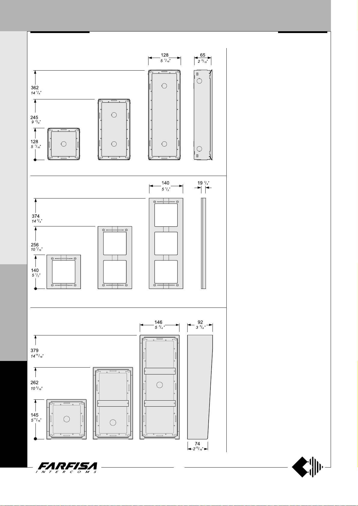
DOOR ST A TIONS
I N T E R C O M S Y S T E M S * V I D E O I N T E R C O M S Y S T E M S
Back box with module frames
MA 71 MA 72 MA 73
Front frames
MA TRIX SERIES
Stainless steel anti-vandalism push-button
panels especially studied to withstand burglary,
penetration of solids and water jets (IP 45
protection degree against the penetration of
external solids and water; IK09 against shocks).
The Matrix push-button panels include back
boxes, module frames, die-cast aluminium
decorative frames, button modules, and
modules with built-in speaker unit (with or without
camera).
The careful selection of modules allows for
multiple application opportunities; from oneway installations to blocks of flats; from intercom
to video intercom installations.
The push-button elements have been developed
to allow both for horizontal and vertical
configuration.
M
A
T
MA 61 MA 63MA 62
R
Rain shelters with module frames
I
X
F
N
4
0
0
MA 91 MA 93MA 92
0
24
(MT10 - Gb2010)
Page 27
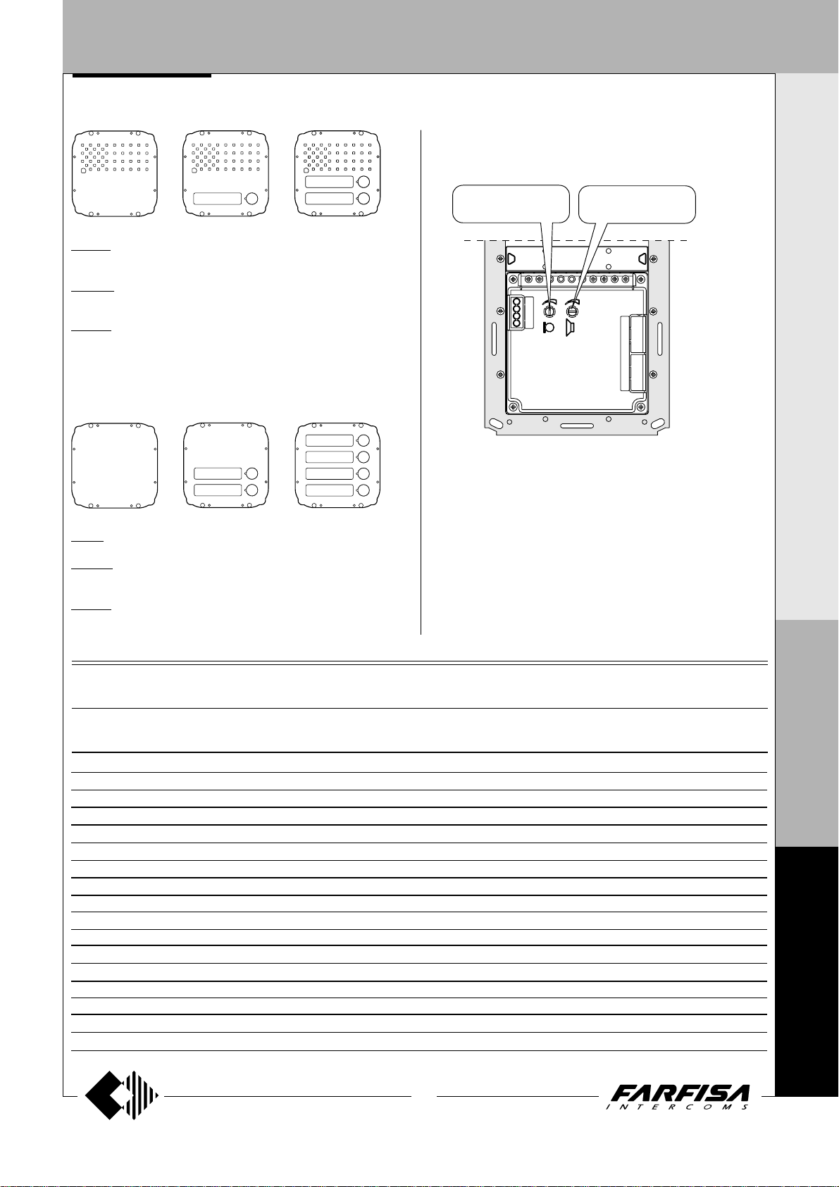
DOOR ST A TIONS
Modules with integrated audio amplifier
Audio adjustments
If necessary, it is possible to adjust the volume of the 2 channels audio
opportunely varying the external knobs.
I
N T E R C O M S Y S T E M S *
MA 10P. Amplified speaker unit with volume adjustment of 2 channels
(reception and transmission), steel front plate and red operation LED.
MA 11P. Same as MA 10P, with call button and name plate panel with
breakproof transparent screen and green LED backlight.
MA 12P. With 2 call buttons.
Push-button modules
MA 20. Blank module in stainless steel.
MA 22S. Module with 2 call buttons and name plate panel with breakproof
transparent screen and green LED backlight.
MA 24S. With 4 call buttons.
See page 32.
Transmitter
adjustable volume
MA10P MA11P MA12P
Receiver
adjustable volume
V
I D E O I N T E R C O M S Y S T E M S
Technical characteristics of MATRIX modules terminal boards
MA10P MA11P MA12P MA20 MA22S MA24S MA42DG MA43DG
MA42CDG MA43CDG
111 1 1
222 2 2
333 3 3
444 4 4
------- AAAAAA
CC C
P1 P1 P
P2
VV
MM
++
EC EC
L- L- L- L- LL+ L+ L+ L+ L+
Reception audio line
Transmission audio line
Power supply input for electric door speaker (6÷12Vdc)
Audio ground
General ground
AC or DC power supply input for nameplate Led (12Vac-dc)
Call push-buttons common
Call push-button
Call push-button
Call push-button
Call push-button
Video signal output (coaxial cable)
Video ground (coaxial shield)
Positive voltage input for camera and Led's (12Vdc)
Camera enable input (ground command)
Alternated power supply input or ground for service Led
AC or DC power supply input for service Led (12Vac-dc)
M
A
T
R
I
X
F
N
4
0
0
25
(MT10 - Gb2010)
0
Page 28
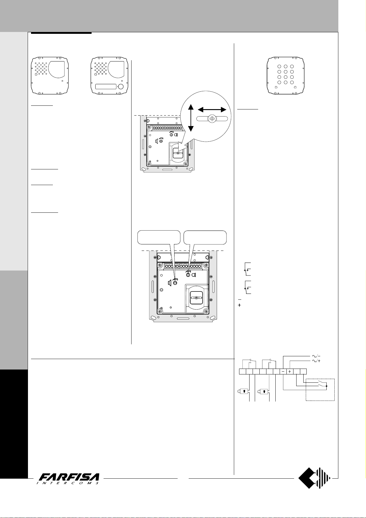
DOOR ST A TIONS
P2 P1
RL1
RL2
For direct activation
of RL1 and RL2
Max 2A
load
Max 2A
load
Power
supply
Power
supply
I N T E R C O M S Y S T E M S * V I D E O I N T E R C O M S Y S T E M S
Video modules with integrated audio amplifier
ACCESS CONTROL KEYPAD
Adjustments
You can manually change the camera framing
by unloosening and adjusting the horizontal
and vertical screws in the desired direction.
MA 42DG. Modules complete with:
- CCD camera with autoiris, fixed 3.6mm lens
and 6 infrared LED’s.
- amplified speaker unit with volume
adjustment of 2 channels (reception and
transmission)
- steel front plate with breakproof transparent
screen
- horizontal and vertical adjustments
- red operation LED
MA 42CDG.
Colour version of model MA42DG.
MA 43DG.
Same as MA42DG, with call button and name
plate panel with breakproof transparent screen
and green LED backlighting.
MA 43CDG.
Colour version of model MA43DG.
Terminals
1 Reception audio line
2 Transmission audio line
3 Power supply input for electric door speaker
(6÷12Vdc)
4 Audio ground
- Ground for Led
+ Positive voltage input for camera and Led
(12Vdc)
C Call push-buttons common
P Call push-button
M
V Video signal output (coaxial cable)
M Video ground (coaxial shield)
A
EC Camera enable input *
L- Negative voltage input for service Led
L+ Positive voltage input for service Led
T
* Operating timed mode if connected to the EC
R
terminal of the push-button panel or continuous mode if grounded.
I
.
Audio adjustments
If necessary, it is possible to adjust the volume
of the 2 audio channels opportunely varying the
external knobs.
Receiver
adjustable volume
MA42 MA42C MA43 MA43C
X
Technical data MA42DG-MA43DG MA42CDG-MA43CDG
Power supply 12±1Vdc 12±1Vdc
Operating current 0.2A 0.4A
Video signal output 1Vpp on 75Ω 1Vpp on 75Ω
Video signal standard CCIR PAL
F
Minimum illumination 2 Lux 2.5 Lux
White balance - auto
Sensor CCD 1/4" B/W CCD 1/3" colour
N
Number of pixels 291,000 291,000
Horizontal frequency 15,625Hz 15,625Hz
Vertical frequency 50Hz 50Hz
Lens 3.6mm; F5 4mm; F4
4
Focus 0.1m ÷ ∞ 0.6m ÷ ∞
Autoiris electronic electronic
Horizontal adjustment ± 15° ± 15°
0
Vertical adjustment ± 15° ± 15°
Operating temperature -10°÷+40°C -10°÷+40°C
0
Max. permissible humidity 80% RH 80%RH
0
(MT10 - Gb2010)
(±15°)
Transmitter
adjustable volume
26
3
1
6
829
7
A405B
FC 52MA. Electronic keypad with 12 keys and
2 relays for lock release and access control of
door stations.
12 programmable access codes for each relay. Programmable door opening time from 1
up 99 sec. for each relay (or bistable operation
of relay). Acoustic and visual confirmation for
entered keys, accepted programming and for
wrong codes.
Technical data
Power supply: 12Vac/dc ±10%
Standby current: 0.02A
Max. current consumption: 0.1A
Contact ratings: 12Vac - 2A
Numbers of codes for relay 1: 12 + direct
Numbers of codes for relay 2: 12 + direct
Activation time for each relay: from 1 to 99 sec.
(or bistable)
Operating temperature: 0° ÷ +40°C
Maximum permissible humidity: 85% RH
Degree of protection IP 45
Terminals
normally closed contact of relay 2
2 normally open contact of relay 2
common contact of relay 2
normally closed contact of relay 1
1 normally open contact of relay 1
common contact of relay 1
ground or alternating voltage input
positive or alternating voltage input
P2 activation of the relay 2; if momentarily
connected to ground it allows the activation for the programmed time
P1 activation of the relay 1; if momentarily
connected to ground it allows the activation for the programmed time
activation
activation
Page 29

DOOR ST A TIONS
DIGITAL PUSH-BUTTON PANEL
DIGIT AL PUSH-BUTT ON P ANEL
3C 4D
2B
1A
6F 7G 8H 9 I 0J
TD4100MA. Matrix series anti-vandalism steel
push-button panel with 14 steel buttons and
alphanumerical LCD. Used to dial and send
calls over FN4000 digital line.
Technical features
Power supply 12Vdc ± 1
Operating current 0.05A
Maximum absorption 0.12A
Door-opening time 3 / 6 sec.
LCD 2 lines x 16 characters
Number of calls (hypothetical) 9999
Memory 250 names
Dimensions 1 module
Operating temperature 0°÷+40°C
Maximum humidity acceptable 90% RH
Terminals
F1 audio from internal stations
F2 audio to internal stations
- ground
+ +12Vdc power supply input
DB serial data bus
P1 direct call button input to the exchanger or to
an user
EC output command for a analog exchanger
(grounded contact upon call and during conversation)
RV video-OFF command (grounded contact
upon call and during conversation)
S1-S2 door opener command (normally open
contacts of relay)
Terminal board for door speaker connection
1 audio receiver
2 audio transmitter
3 +12Vdc (0.2A) power supply output
4 audio ground
Terminal board for electronic index connection
CS clock signal
DS data input
V+ +12Vdc (0.2A) power supply output
GN ground
5E
PROGRAMMING
To program you must:
Move the jumper J1 on the back of the push-
button panel from A to B; the display shows
“Programming / type:
Dial the requested programming code (
table
) and press to confirm.
“.
see
At the end of each programming phase,
move the jumper J1 back to A.
Positions of jumper J1
A = operation mode
B = programming mode
A B
J1 J1
CS
DS
V+
GN
Table 1.
Programming phases
0000 Entry of codes for door lock release /
address of push-button P1 / address of
external station PE
0001 Entry-modification-erasing of names
in the electronic index
0002 Language selection
0003 System programming
0004 Entry of text to be shown on the display
0005 Loading names from PC
0006 Alphabetical ordering of names
Entry of codes for door lock / address
push-button P1 / address of external
station PE
Enter the code 0000 to access the “entry of
door lock codes” mode. The display shows
“PASSWORD 0 / ”.
Dial the first opening code on the keypad, for
example 7890; the display shows
“PASSWORD 0 / 7890”.
Press ; the display shows
1 / ”.
Dial the second opening code on the keypad,
for example 1234; the display shows
“PASSWORD 1 / 1234”.
(code 0000)
“PASSWORD
Press ; the display shows
“PASSWORD
2 / ”.
Repeat the operation to enter a maximum of
16 codes. When you press
to confirm
automatically the last code (PASSWORD
15) you enter the “entry of address P1
code” mode. You can now store the number
of the internal station that can be called directly
by pushing a button connected between
terminals P1 and -.
Press ; the display shows
“P1 / 1000”.
Press to delete the code shown on the
display and enter the number of the internal
station you want to enable for the direct call
function.
Press to confirm and go to the “entry of
address PE code”; the display shows
You can enter the address for the
/ ”.
“PE
external station. The push-button panels can
be coded with numbers from 9950 to 9979.
Dial the addresses and press to confirm.
You go back address to the “entry of door
lock codes” mode. The display shows the
code stored as password 0 (
/
stored code)”.
PASSWORD 0
To exit programming move the jumper J1
back to the original position (from B to A).
Note. To delete a password or the address
associated with P1 and PE it is necessary first
to select the code you want to erase and that
press
and again.
Entry / modification / erasing of names in
the electronic index
(code 0001)
You can enter 32 characters, of which 28
characters for the name and the last 4 characters
on bottom right of display are for the internal
station number. When searching for characters,
the display shows uppercase letters, low case
letters, numbers, characters . <> and space in
a sequence.
Enter the names from the top and from left to
right. You must enter at least a number in the
last place on bottom right of the display to save
the name (see “deleting a name”). The push-
button panel reorders the list in alphabetical
order every time you enter and confirm a name.
I N T E R C O M S Y S T E M S * V I D E O I N T E R C O M S Y S T E M S
M
A
T
R
I
X
to optional expansion modules
to the installation to be made
J1
J2, J3
F
CS
DS
V+
GN
S2
S1
EC
RV
P1
DB
F2
F1
J1, J2, J3
jumpers for programming
jack for the connection to the PC
1234
to the door speaker
(see pages 27 and 29)
(see page 29)
N
4
0
0
0
27
(MT10 - Gb2010)
Page 30
DOOR ST A TIONS
DIGITAL PUSH-BUTTON PANEL
I N T E R C O M S Y S T E M S * V I D E O I N T E R C O M S Y S T E M S
Function of buttons
Hold this button pressed to scroll the list of
existing names
Hold this button pressed to move the cursor
to the name characters
Hold this button pressed to scroll down the
list of characters
Hold this button pressed to scroll up the list
of characters
Entry of names
Move the jumper J1 from A to B.
Enter the code 0001; the display shows the
first name. The display is empty if no names
are programmed.
Press or to select the character for the
first cell; press
or to select the character for the
press
second cell; continue until you have entered
the complete name and code. Press
you have entered the number in the last cell
on bottom right; the display
USER / YES < > NO
press
If confirmed, the display shows the second
name. The display is empty if no names are
programmed.
Once you have confirmed the last name,
move the jumper back to the original position
(from B to A). The display shows “
and an automatic status bar. Normal operation
is restored after a few seconds and the
display shows the initial text (see
“
Notes. Once you have entered 250 names
(max number of users that can be stored) the
display shows “
bar. After a few seconds the display shows
M
“Programming / type:
with programming.
A
You can enter 2 or more names with the same
call number (i.e. different family names in the
same apartment).
T
to modify the name.
Operation”).
to go to the second cell;
”; press to confirm;
waiting”
and an automatic status
“ and you can continue
R
after
shows “STORE
waiting”
- Modification of names
Press to search for the name you want to
modify; (hold the button pressed for quick
searching).
Press to go to the character you want to
modify.
Select the character with (forward)
(backward). Enter a space to delete a letter.
Repeat the operation until you have
completed the name modification.
Once you have completed the modification,
pressed until the display shows
hold
“STORE USER / YES < > NO”
confirm or
- Add names to the list
To add a new name to the existing list press
to scroll the list; the display is empty after the
last name. To enter a new name follow the
operations described in “Entry of names”. If
confirmed, the name is placed in the list in
alphabetical order.
- Delete names from the list
Press to search for the name you want to
delete; (hold the button pressed for quick
searching).
Press to go to the last cell (bottom right);
enter a space to delete the existing number.
Press again; the display shows
USER / YES < > NO”
to go back to the name.
The next name is displayed after you have
deleted the name.
Language selection
You can choose the language from 6 different
options (Italian, English, French, German,
Spanish and Portuguese) in operation mode.
Move the jumper J1 from A to B.
Enter the code 0002; the display shows
“Italiano”
programmed language.
Press or to select the language.
Press to confirm; the display shows
“Programming / type: “
to modify the name again.
Press to confirm or
(code 0002)
in case of first programming or the
Press to
“DELETE
.
System programming
You can change or activate the functions of the
push-button panel
Move the jumper J1 from A to B.
Enter the code 0003; the display shows
0 = 0 / 0 < > 1”
“bit 0 = 1 / 0 < > 1”
programming.
Press to select 1 or to select 0.
Press to confirm and go to the next bit
(see code table with descriptions).
Once you have confirmed the value of the last
bit (bit7), the display shows
type:
programming.
- Enabling of alphanumerical calling mode
(bit 4)
If the installation is divided into several blocks,
it could be useful call each block with a letter
instead of a number (e.g. block "A", block "B",
etc.). If you program such a operating mode the
number of thousands in the user code is displayed as a letter and not as a number (1=A,
2=B, 3=C, 4=D, 5=E, 6=F, 7=G, 8=H, 9=I, 0=J).
Please consider that it is only a question of
displaying because the codes send to the users are always numerical codes, really the user
identified by the code "B001" is stored as user
2001 and this code must be programmed on its
intercom, videointercom or floor decoding
module. It is still important to note that if an
alphanumeric code, with less than 4 digit, is
entered on the keypad, the system automatically fills the empty numbers with zeros, for
instance entering only the code "E" the display
shows the code "E000" and the system transmits the code 5000. In the same way if the code
"E2" is entered the display shows "E002" and
the system transmits the code 5002, therefore
the user you want to be identified by the code
"E002" must be programmed as user 5002.
in case of first programming or
“ and you can continue with
(code 0003)
(see table).
if changed in a previous
I
Table 2 - System programming codes
X
Programming Function description Default Value entered with buttons
code settings
(code 0003)
= 0 = 1
“bit
“Programming /
F
N
4
0
0
0
bit 0 door lock activation time 3 sec. 3 sec. 6 seconds
bit 1 activation upon call from internal station
bit 2 door lock activation with
bit 3 not used - - -
bit 4 call numbers displayed with initial letter
bit 5 activation of personalised initial screen
bit 6 deactivation of ACI FARFISA and activation of personalised text NO N O YES
bit 7 deactivation/activation of tone generator NO NO YES
(1)
This function allows the internal stations to press the door lock button, start a conversation with the external station (in case of more external
stations in parallel the function must be activated on one external station only) and activate the door lock by pressing the button again.
(2)
This functions allows for quicker door lock activation by pressing rather than dialling the code 00+ . For example: press + password
+
.
(3)
You can alternate
“ACI FARFISA”
(2)
with the personalised text (see “Personalisation of text to be shown on the display”).
(1)
(see relative paragraph)
(3)
NO NO YES
NO NO YES
NO NO YES
NO NO YES
28
(MT10 - Gb2010)
Page 31

DOOR ST A TIONS
DIGITAL PUSH-BUTTON PANEL
Personalisation of text to be shown on the
display
(code 0004)
You can modify the text shown on the display
during normal operation or idle state. To display
it program bit5 (“system programming”).
Move the jumper J1 from A to B.
Enter the code 0004; the display shows
“, in case of first programming, or the text you
want to replace.
For information on how to enter the characters
see “entry of names”.
Press to confirm; the display shows
“Programming / type:
with programming.
You must program properly bit5 in system
programming phase to enable to display it.
Loading names from PC
You can load names in the electronic index
directly from your PC.
Load the names on the PC using a dedicated
software application (software supplied on
demand).
Turn off the push-button panel and the PC.
Connect the PC serial port to the stereo jack
on the back of the push-button panel with a
cable as shown in the figure.
Move the jumpers J2 and J3 on the back of
the push-button panel from A to B (also the
jumper J1 must be on B).
Turn ON the PC and then the push-button
panel.
On the push-button panel enter the code
0005; the display shows
/ in progress 0”.
Download the names from the PC within 15
seconds; the display shows
—> PC / in progress 1”,
PC / in progress 2”
names.
At the end of download the push-button
deletes the existing names. The first line of
the display shows
line shows a status bar to show the progress
of the deletion operation. At the end the
display shows
Turn off the push-button panel and then the
PC.
Disconnect the cable from PC and push-
button panel.
Move the jumpers J2 and J3 back to A; move
the jumper J1 back to A if you have completed
programming, otherwise continue with
programming.
“ and you can continue
“TD4100MA > PC
“TD4100MA <
“
TD4100MA <—>
and then the downloaded
“waiting”
“Programming / type: “
and the second
“??
.
PC serial port
1
6
2
7
3
8
4
9
5
1234
TD4100MA
4
Stereo jack
PC
A B
J2 J2
J3 J3
Ø = 2,5mm
5
2
Alphabetical ordering of names
You can list the names in alphabetical order
(from A to Z).
3
2
5
3
Enter the code 0006; the first line of the
display shows
shows a status bar; at the end of the operation
the push-button panel returns automatically
to the programming mode (the display shows
“Programming / type: “
Return to operation mode
Once you have completed programming, move
the jumper J1 back to A; the display shows
“
ACI FARFISA / press < >
entered during programming (see
"Personalisation of text to be shown on
the display”).
“waiting”
and the second line
).
” or the text you have
I N T E R C O M S Y S T E M S * V I D E O I N T E R C O M S Y S T E M S
M
A
T
R
I
X
Tone table
012345
012345
012345
012345
Free - The internal station you have called is ringing
Hold-on -
End of conversation - 10 seconds before conversation ends
Confirmation -Sending of call, door lock opening during conversation and acknowledgement of door lock code
F
N
The exchanger has put the push-button panel on hold
4
0
0
0
29
(MT10 - Gb2010)
Page 32

DOOR ST A TIONS
DIGITAL PUSH-BUTTON PANEL
I N T E R C O M S Y S T E M S * V I D E O I N T E R C O M S Y S T E M S
OPERATION
Check that all connections are correct. Connect
the power supply unit to the mains; the displays
shows the software version of the push-button
panel for 3 seconds followed by “
/ press < >
(< > in alternate mode).
ACI FARFISA
Dial the user number, check that the number is
correct on the display “
error press
Press
“
calling / ----
and dial the correct number.
to make the call. A tone and the text
” confirm that the call has been
dialling /
----"; in case of
made.
If the user is busy or if the user code does not
exist the display shows “
busy / ”
for 3 seconds.
If the user exists you hear the ringing tone and
the display shows “
ringing / ----”.
You can select the internal station from the
names in the electronic index. Press
search for the internal station and press
send the call.
The called intercom rings for about 25 seconds.
The called user picks up the handset to interrupt
the call and enables the conversation with the
external station for 60 seconds. The display
shows “
connection /---- ”.
The text on the display starts flashing 10 seconds
before conversation ends. To continue
conversation for additional 60 seconds press
again.
Press the intercom button to release the door
lock. Door lock activation time is 3 seconds (or
6 seconds if properly programmed).
Replace the handset to restore the idle state.
Numbers that are not sent or deleted go off after
25 seconds.
M
A
"Dialling"
T
or to
to
In installations with 2 or more digital pushbutton panels, when a call is made from one
push-button panel, the other push-button panels
are deactivated and their display shows
/ ”.
Wait until the line is free to make the call.
“busy
In installations with doorkeeper exchanger
in “Day” mode without direct dialling function,
all calls are sent to the exchanger.
Once the call is received, the operator can put
the push-button panel on hold and call the internal
station; the push-button display shows
“hold-
on / ”.
If the operator connects the internal station with
the push-button panel, the display returns to the
conversation status. The number displayed on
the push-button panel is the number of the
internal station called by the operator and it
may not correspond to the called number
because of the call transfer function.
Door lock release
The door lock, even if in busy state, can be
released from the push-button panel by dialling
one of the 16 four digit personal access codes
you have stored.
Door lock activation
- Dial 00
- Press
- Dial the personal access code within 10
seconds; each digit is visualised with * instead
of
- Press
the confirmation tone and the push-button
panel returns to the current system operation
mode (free or busy).
; the display shows “
“
.
to release the door lock; you hear
Password
/
Composition MATRIX digital push-button
panel
Audio composition
traditional
3C 4D
2B
Composed of:
1 TD4100MA
1 MA10P
1 MA62
1 MA72
5E
3C 4D
2B
1A
6F 7G 8H 9I 0J
5E
1A
6F 7G 8H 9I 0J
vertical horizontal
with push-button for the direct call of an user
3C 4D
2B
Composed of:
1 TD4100MA
1 MA11P
1 MA62
5E
1 MA72
3C 4D
2B
1A
6F 7G 8H 9I 0J
5E
1A
6F 7G 8H 9I 0J
vertical horizontal
Audio-video composition
traditional
Composed of:
1 TD4100MA
1 MA42DG or
5E
3C 4D
2B
5E
3C 4D
2B
1A
6F 7G 8H 9I 0J
vertical horizontal
1A
6F 7G 8H 9I 0J
MA42CDG
1 MA62
1 MA72
with push-button for the direct call of an user
Composed of:
1 TD4100MA
1 MA43DG or
5E
3C 4D
2B
5E
3C 4D
2B
1A
6F 7G 8H 9I 0J
vertical horizontal
1A
6F 7G 8H 9I 0J
MA43CDG
1 MA62
1 MA72
R
I
X
F
N
4
0
0
0
or “Search”
s
ELEZIONE
1234
3C 4D
2B
1A
6F 7G 8H 9 I 0J
ROSSI GIOVANNI
1234
3C 4D
2B
1A
6F 7G 8H 9 I 0J
5E
C
s
C
HIAMATA
1234
5E
3C 4D
2B
1A
6F 7G 8H 9 I 0J
5E
QUILLA
1234
3C 4D
2B
1A
6F 7G 8H 9I 0J
5E
ONVERSA
1234
3C 4D
2B
1A
6F 7G 8H 9 I 0J
5E
30
(MT10 - Gb2010)
Page 33

DOOR STATIONS
PUSH-BUTTON PANEL WITH DIGITAL ENCODER
DIGITAL ENCODER
CD4130MA.
It allows for using Matrix conventional pushbutton panels in FN4000 digital systems.
Complete with busy state signal.
Technical features
Power supply: 12Vdc ± 1
Operating current: 0.1A
Maximum number of users: 63
Door-opening time: 3 sec.
Dimensions: 1 module
Operating temperature: 0° ÷ +40°C
Maximum permissible humidity: 90% RH
Terminals
F1 audio from internal stations
F2 audio to internal stations
- general ground
+ +12Vdc power input
DB serial data bus
EC output command for an analog exchanger
(grounded contact upon call and during
conversation)
SV video ON command (temporary ground
contact - 0.5 seconds approx.)
RV video-OFF command (grounded contact
upon call and during conversation)
S1-S2 door opener command (normally open
contacts of relay)
Terminal board for door speaker connection
1 audio receiver
2 audio transmitter
3 +12Vdc (0.2A) power output
4 audio ground
st
call push-button *
P1 1
nd
call push-button *
P2 2
The CD4130MA digital encoder can manage max.
63 users. If more calls are necessary, another
CD4130MA must be connected in parallel and
properly programmed.
Programming
The CD4130MA digital encoder can be programmed to change the first user code (0 by
default). Programming must be made only if more
than 63 users are present (the second CD4130MA
must be coded starting from number 63 or higher)
or in installations with multiple entrances and in the
presence of digital exchanger. In this case the
decoding modules and the digital exchanger must
be compatibly programmed.
Attention. The code of the first programmed user
is not accessible by the system.
For example: the first CD4130MA with user codes
from 0 to 63 (default programming; accessible
codes are from 1 to 63), the second CD4130MA
with user codes from 63 to 126 (accessible codes
are from 64 to 126). In case of multiple entrances,
the first CD4130MA with user codes from 100 to
163 (accessible codes are from 101 to 163), the
second CD4130MA with user codes from 200 to
263 (accessible codes are from 201 to 263).
Programming can be made with the TD4100MA
digital push-button panel or the PDX4000 doorkeeper exchanger (if present in the installation) as
follows:
- unloosen the 4 screws to remove the cover
- remove jumper J1 to free the 2 poles
J1
JP3
J1
F1
F2
- dial the first user code on the TD4100MA pushbutton panel keypad or the PDX4000 doorkeeper exchanger and press Enter; the speaker
unit generates an acknowledge tone
s
ELEZIONE
3C 4D
2B
1A
6F 7G 8H 9I 0J
1234
5E
C
HIAMATA
3C 4D
2B
1A
6F 7G 8H 9 I 0J
1234
5E
- insert jumper J1 to short-circuit the 2 poles
J1
JP3
J1
- make a call to a user to check the number
- replace the cover.
The last number is stored if more codes are
sent.
If the system does not include a TD4100MA
push-button panel or a PDX4000 doorkeeper
exchanger, they can be temporarily added for
programming by connecting the +, - and DB
terminals to the corresponding terminals of the
digital encoder (as shown in the drawing of the
right side).
Connection of a push-button panel
TD4100MA for programming the encoder
CD4130MA
CD4130MA
1234
F1
F2
DB
DB DB
P1
RV
EC
S1
S2
TD4100MA
GNV+DS
CS
F1
F2
DB
P1
RV
EC
S1
S2
Programming of the operating modes
- Remove the J1 jumper for entering in the
programming mode.
- Dial from the keypad of TD4100MA or
PDX4000 the required code (see table 1)
and press button “enter”; an acknowledge
tone will be heard.
- For exit to the programming mode insert the
J1 jumper.
In the case of several codes dialled, only the
last one is stored.
I N T E R C O M S Y S T E M S * V I D E O I N T E R C O M S Y S T E M S
M
A
T
R
I
* To be connected only if included in the pushbutton panel composition.
CD4130MA
1
2
3
4
P1
P2
MA10P-11P-12P
1
MA42-42CDG
2
MA43-43CDG
3
4
C
P1
P2
to the MA10P, MA11P, MA12P door
speaker or MA42DG, MA42CDG,
MA43DG, MA43CDG cameras
to JP1 of the first
MA22S or MA24S
module
1
2
3
4
P1
P2
to the installation to be made
F1
F2
DB
P1
RV
EC
S1
S2
31
(MT10 - Gb2010)
Table 1. Operating modes
Operating Codes to dial
mode
9990 9991 9994 9995
Relay activation time 3 sec. 6 sec. 3 sec. 6 sec.
Monitoring from internal No No Yes Yes
station to door station * *
* Enabling this function from any internal station it is
possible, by pressing the button
, get the connection
with the door station and activate the lock release pressing
again the button
.
X
F
N
4
0
0
0
Page 34

DOOR STATIONS
a
a
a
a
a
a
a
a
a
a
a
a
a
a
a
a
a
a
a
a
a
a
a
a
a
a
a
a
a
a
a
a
a
a
a
a
a
a
a
a
a
a
a
a
a
a
a
a
a
a
a
a
a
a
a
a
a
a
a
a
a
a
a
a
a
a
a
a
a
a
a
a
a
a
a
a
a
a
a
a
aaaaaaaaaaaaaaaaaaaaaaaaaaaaaaa
PUSH-BUTTON PANEL WITH DIGITAL ENCODER
I N T E R C O M S Y S T E M S * V I D E O I N T E R C O M S Y S T E M S
PUSH-BUTTON MODULES WITH INTEGRATED ENCODING
BOARD
st
1
button
nd
button
2
st
button
1
2nd button
fig.1
The button modules with integrated
encoding board, thanks to the
connection to the encoder module
CD4130MA, allow the calls in FN4000
systems.
MA 22S. Module with antivandal
stainless steel front plate and two call
buttons. Complete with name holders
with transparent screen green backlighting, resistant to breaking and connection cable to the next module.
MA 24S. Same as the previous, but
with 4 call buttons.
Terminals
A AC or DC power supply input for
nameplate Led (13Vac or dc)
aaaaaaaaaaaaaaaaaaaaaaaaaaaaa
aaaaaaaaaaaaaaaaaaaaaaaaaaaaa
aaaaaaaaaaaaaaaaaaaaaaaaaaaaa
aaaaaaaaaaaaaaaaaaaaaaaaaaaaa
aaaaaaaaaaaaaaaaaaaaaaaaaaaaa
aaaaaaaaaaaaaaaaaaaaaaaaaaaaa
aaaaaaaaaaaaaaaaaaaaaaaaaaaaa
M
A
T
R
I
X
F
N
4
0
0
0
aaaaaaaaaaaaaaaaaaaaaaaaaaaaa
aaaaaaaaaaaaaaaaaaaaaaaaaaaaa
aaaaaaaaaaaaaaaaaaaaaaaaaaaaa
aaaaaaaaaaaaaaaaaaaaaaaaaaaaa
aaaaaaaaaaaaaaaaaaaaaaaaaaaaa
aaaaaaaaaaaaaaaaaaaaaaaaaaaaa
aaaaaaaaaaaaaaaaaaaaaaaaaaaaa
aaaaaaaaaaaaaaaaaaaaaaaaaaaaa
aaaaaaaaaaaaaaaaaaaaaaaaaaaaa
aaaaaaaaaaaaaaaaaaaaaaaaaaaaa
aaaaaaaaaaaaaaaaaaaaaaaaaaaaa
aaaaaaaaaaaaaaaaaaaaaaaaaaaaa
aaaaaaaaaaaaaaaaaaaaaaaaaaaaa
aaaaaaaaaaaaaaaaaaaaaaaaaaaaa
aaaaaaaaaaaaaaaaaaaaaaaaaaaaa
aaaaaaaaaaaaaaaaaaaaaaaaaaaaa
aaaaaaaaaaaaaaaaaaaaaaaaaaaaa
aaaaaaaaaaaaaaaaaaaaaaaaaaaaa
aaaaaaaaaaaaaaaaaaaaaaaaaaaaa
aaaaaaaaaaaaaaaaaaaaaaaaaaaaa
aaaaaaaaaaaaaaaaaaaaaaaaaaaaa
aaaaaaaaaaaaaaaaaaaaaaaaaaaaa
aaaaaaaaaaaaaaaaaaaaaaaaaaaaa
aaaaaaaaaaaaaaaaaaaaaaaaaaaaa
aaaaaaaaaaaaaaaaaaaaaaaaaaaaa
aaaaaaaaaaaaaaaaaaaaaaaaaaaaa
aaaaaaaaaaaaaaaaaaaaaaaaaaaaa
aaaaaaaaaaaaaaaaaaaaaaaaaaaaa
aaaaaaaaaaaaaaaaaaaaaaaaaaaaa
aaaaaaaaaaaaaaaaaaaaaaaaaaaaa
aaaaaaaaaaaaaaaaaaaaaaaaaaaaa
aaaaaaaaaaaaaaaaaaaaaaaaaaaaa
aaaaaaaaaaaaaaaaaaaaaaaaaaaaa
rd
button
3
4th button
AC power supply or ground input for nameplate Led
Installation and connections
- Connect the digital encoder to the connector JP1 of the first MA22S or MA24S
module using the flat cable supplied with
the digital encoder.
- Connect the connector JP2 of the first
MA22S or MA24S module to the
connector JP1 of the second MA22S or
MA24S module using the flat cable
supplied with the product.
- Connect in the same way all the other
MA22S or MA24S modules.
- Remove the flat cable from the last
MA22S or MA24S module because it is
not used.
32
(MT10 - Gb2010)
Programming
The microswitches, present on the back of the MA22S or
MA24S, allow the digital encoder to recognize the code of the
connected buttons, consequently they must be programmed
properly. The code set on the microswitches (
the following page
st
1
push-button of the module (
buttons on the module automatically are associated the next
addresses.
Important notes
- Pay attention when program code 0 (address interval 0-3)
because in this case the first push-button from the top does
not call any user. This is due to the fact that the system does
not recognize the address 0 (zero) as a valid address.
- In the case of using module MA22S, which has only 2 push-
buttons, addresses associates to the 3rd and 4th pushbutton will be lost.
The address of the Called User is obtained combining the
address associated to the First button of the module at which
the push-button is connected to and the Address associated
to the Encoder according to the following rule:
Called User Address (IUC) by pressing the buttons of the
MA22S or MA24S module = Address Associated to the
Encoder (IAC) + Number Associated with Button (NAP)
of the MA22S or MA24S module.
General rule: IUC = IAC + NAP
General rule applied to the first example below;
- if you press the first button from above of the MA24S:
100 (IAC) + 4 (1
the user with address 104 will be called.
Examples:
- In this example the
buttons with call the
users 104, 105,
106 and 107.
- In this example the
buttons with call the
users 101, 104,
105, 106 and 107.
Addresses 100,
102 and 103 are
not available.
) determines the address associate to the
st
NAP) = 104 (IUC)
see fig.1
see tables on
); the other push-
Page 35

DOOR ST A TIONS
PUSH-BUTTON PANEL WITH DIGITAL ENCODER
Example of order used to associate
numbers with buttons
MA22S
MA24S
3rd NAP and 4th NAP
are not usable
Code to
be set
0
4
8
12
16
20
24
28
32
36
40
44
48
52
Numbers associated with
buttons- NAP
st
NAP = 0
1
nd
2
NAP = 1
rd
NAP = 2
3
th
NAP = 3
4
1st NAP = 4
nd
NAP = 5
2
rd
3
NAP = 6
th
NAP = 7
4
st
1
NAP = 8
nd
NAP = 9
2
rd
3
NAP = 10
th
NAP = 11
4
st
1
NAP = 12
nd
NAP = 13
2
rd
3
NAP = 14
th
NAP = 15
4
st
NAP = 16
1
nd
2
NAP = 17
rd
NAP = 18
3
th
4
NAP = 19
st
NAP = 20
1
nd
2
NAP = 21
rd
NAP = 22
3
th
4
NAP = 23
st
1
NAP = 24
nd
2
NAP = 25
rd
NAP = 26
3
th
4
NAP = 27
st
NAP = 28
1
nd
2
NAP = 29
rd
NAP = 30
3
th
4
NAP = 31
st
NAP = 32
1
nd
NAP = 33
2
rd
3
NAP = 34
th
4
NAP = 35
st
NAP = 36
1
nd
2
NAP = 37
rd
NAP = 38
3
th
4
NAP = 39
st
NAP = 40
1
nd
2
NAP = 41
rd
3
NAP = 42
th
NAP = 43
4
st
1
NAP = 44
nd
NAP = 45
2
rd
3
NAP = 46
th
4
NAP = 47
st
1
NAP = 48
nd
NAP = 49
2
rd
3
NAP = 50
th
NAP = 51
4
st
1
NAP = 52
nd
NAP = 53
2
rd
3
NAP = 54
th
4
NAP = 55
Pushbutton
microswitch
ON
12345
ON
12345
ON
12345
ON
12345
ON
12345
ON
12345
ON
12345
ON
12345
ON
12345
ON
12345
ON
12345
ON
12345
ON
12345
ON
12345
OPERATION
Code to
be set
56
60
Numbers associated with
buttons- NAP
st
NAP = 56
1
nd
NAP = 57
2
rd
NAP = 58
3
th
NAP = 59
4
1st NAP = 60
nd
2
NAP = 61
rd
3
NAP = 62
th
NAP = 63
4
Pushbutton
microswitch
ON
12345
ON
12345
Tone table
012345
Free - Indicates that the line is free
012345
Indicates that the called user is busy
Busy -
012345
Confirmation - Indicates that programming was ex-
ecuted
Check that all the connections are correct.
Connect the power supply unit to the mains.
To make a call press the button corresponding
to the desired user. Call is confirmed by an
acknowledge tone, if the communication line is
available, or denied by a busy tone if the
communication line is not available (see tone
table).
Called equipment rings only once, but if in this
phase the same calling button on the external
station is pressed again the equipment will ring
another time.
The called user picks up the handset enables
the conversation with the external station for 60
seconds.
A tone will advise the user 10 seconds before
the conversation ends. To continue
conversation for additional 60 seconds on the
external station the calling button must be
pressed again.
Press the
Door lock activation time is 3 seconds (or 6
seconds according to the system
programming).
Replace the handset to end the conversation
and restore the idle state.
In installations with 2 or more external door
stations when a call is made from one pushbutton panel, the other push-button panel are
deactivated with a busy indication (red LED
flashing on the audio or audio/video module).
Wait until the line is free to make a call.
door station 1
door station 2
busy
012345
End of conversation - 10 seconds before conver-
sation ends
012345
Programming and waiting
Indicates the programming mode or the waiting status of the
external user
33
(MT10 - Gb2010)
I N T E R C O M S Y S T E M S * V I D E O I N T E R C O M S Y S T E M S
button to release the door lock.
M
A
T
R
I
X
F
N
4
0
0
0
Page 36

DOOR ST A TIONS
I N T E R C O M S Y S T E M S * V I D E O I N T E R C O M S Y S T E M S
INSTALLATION
5E
3C 4D
2B
1A
6F 7G 8H 9I 0J
"
5
5
Insertion of spacers between back boxes. Spacers
and cable bushing (not supplied with the products)
must be inserted before brick work.
Flush mounting and cables placing.
Place the push-button panel back box at a
height of about 1.65m
keeping the front edges flush-mounted and
vertical to the finished plaster.
Position the camera in such a way that
sunlight or other direct or reflected light
sources with high intensity do not hit
the camera lens.
(5' 5")
M
A
T
R
I
X
F
from the floor
Mounting modules.
N
Openings for cables.
4
0
0
0
For easier connection to the electrical system, it is
recommended to insert the metal plate supplied
with the product in the back box opening, as
shown in the figure. The plate is used to hook the
frame with pre-assembled modules. Leave the
plate in the box to reuse it for maintenance
operations.
34
(MT10 - Gb2010)
Page 37

DOOR ST A TIONS
a
a
a
a
a
a
a
a
a
a
a
a
a
a
a
a
a
a
a
a
a
a
a
a
a
a
a
a
a
a
a
a
a
a
a
a
a
a
aaaaaaaaaaaaaa
Connection of wires to module terminal boxes.
3C 4D
2B
1A
6F 7G 8H 9I 0J
I N T E R C O M S Y S T E M S * V I D E O I N T E R C O M S Y S T E M S
5E
3C 4D
2B
1A
6F 7G 8H 9I 0J
5E
Fixing of frame to back
box. Align the frame
before tightening the
screws.
Rain shelters
Fixing of frame to module frame.
aaaaaaaaaaaa
aaaaaaaaaaaa
aaaaaaaaaaaa
aaaaaaaaaaaa
aaaaaaaaaaaa
aaaaaaaaaaaa
aaaaaaaaaaaa
aaaaaaaaaaaa
aaaaaaaaaaaa
aaaaaaaaaaaa
aaaaaaaaaaaa
aaaaaaaaaaaa
aaaaaaaaaaaa
aaaaaaaaaaaa
aaaaaaaaaaaa
aaaaaaaaaaaa
aaaaaaaaaaaa
aaaaaaaaaaaa
aaaaaaaaaaaa
M
A
T
R
I
X
Apply the protection gaskets supplied with the product
on the internal part of the frame openings.
F
N
Fixing of frame to rain shelter. Align
the frame before tightening the
* Long screws can be used to anchor
the frame during wire connection to
modules.
35
(MT10 - Gb2010)
screws.
4
0
0
0
Page 38

DOOR ST A TIONS
I N T E R C O M S Y S T E M S * V I D E O I N T E R C O M S Y S T E M S
1 button 6 buttons2 buttons 2 buttons
Examples of installations in intercom systems
4 buttons
5 buttons
18 buttons14 buttons 16 buttons 26 buttons10 buttons
6 buttons4 buttons
M
A
T
R
I
X
F
N
4
0
0
0
N°
calls
1
2
4
5
6
8
9
10
12
14
16
18
22
25
26
28
30
32
34
38
42
Dimensions
140x256x19
(5 1/2" x 10 1/16" x 3/4")
140x374x19
(5 1/2" x 14 3/4" x 3/4")
280x256x19
(11" x 10 1/16" x 3/4")
280x374x19
(11" x 14 3/4" x 3/4")
560x256x19
(22 1/16" x 10 1/16" x 3/4")
420x374x19
(16 9/16" x 14 3/4" x 3/4")
560x374x19
(22 1/16" x 14 3/4" x 3/4")
Encoder
module
1 CD4130MA
1 CD4130MA
1 CD4130MA
1 CD4130MA
1 CD4130MA
1 CD4130MA
1 CD4130MA
1 CD4130MA
1 CD4130MA
1 CD4130MA
1 CD4130MA
1 CD4130MA
1 CD4130MA
1 CD4130MA
1 CD4130MA
1 CD4130MA
1 CD4130MA
1 CD4130MA
1 CD4130MA
1 CD4130MA
1 CD4130MA
Door speaker
modules
1 MA11P
1 MA12P
1 MA10P
1 MA11P
1 MA12P
1 MA10P
1 MA11P
1 MA12P
1 MA10P
1 MA12P
1 MA10P
1 MA12P
1 MA10P
1 MA11P
1 MA12P
1 MA10P
1 MA12P
1 MA10P
1 MA12P
1 MA10P
1 MA12P
(MT10 - Gb2010)
38 buttons28 buttons 30 buttons
42 buttons
Composition board of Matrix push-button panels.
Button modules and
blank module
-
1 MA24S
1 MA24S
1 MA24S
2 MA24S
2 MA24S
2 MA24S
3 MA24S
3 MA24S
4 MA24S
4 MA24S
5 MA24S
6 MA24S
6 MA24S
7 MA24S
7 MA24S
8 MA24S
8 MA24S
9 MA24S
10 MA24S
36
Front
frames
-
-
-
-
-
-
-
1 MA20
1 MA20
-
-
1 MA22S
-
-
-
2 MA20
2 MA20
1 MA22S
-
1 MA62
1 MA62
1 MA63
1 MA63
1 MA63
2 MA62
2 MA62
2 MA62
2 MA63
2 MA63
2 MA63
2 MA63
4 MA62
4 MA62
4 MA62
3 MA63
3 MA63
4 MA63
4 MA63
4 MA63
4 MA63
(*) Rain shelters are used in replacement of back boxes
Back box with
module frames
1 MA72
1 MA72
1 MA73
1 MA73
1 MA73
2 MA72
2 MA72
2 MA72
2 MA73
2 MA73
2 MA73
2 MA73
4 MA72
4 MA72
4 MA72
3 MA73
3 MA73
4 MA73
4 MA73
4 MA73
4 MA73
Rain shelters
(*)
1 MA92
1 MA92
1 MA93
1 MA93
1 MA93
-
-
-
-
-
-
-
-
-
-
-
-
-
-
-
-
Page 39

DOOR ST A TIONS
1 button 5 buttons1 buttons
9 buttons
Examples of installations in video intercom systems
4 buttons
4 buttons
17 buttons12 buttons 16 buttons 25 buttons
5 buttons2 buttons
I N T E R C O M S Y S T E M S * V I D E O I N T E R C O M S Y S T E M S
N°
calls
1
2
4
5
6
8
9
12
13
14
16
17
22
23
25
26
29
33
36
38
41
Dimensions
140x256x19
(5 1/2" x 10 1/16" x 3/4")
140x374x19
(5 1/2" x 14 3/4" x 3/4")
280x256x19
(11" x 10 1/16" x 3/4")
280x374x19
(11" x 14 3/4" x 3/4")
560x256x19
(22 1/16" x 10 1/16" x 3/4")
420x374x19
(16 9/16" x 14 3/4" x 3/4")
560x374x19
(22 1/16" x 14 3/4" x 3/4")
Encoder
module
1 CD4130MA
1 CD4130MA
1 CD4130MA
1 CD4130MA
1 CD4130MA
1 CD4130MA
1 CD4130MA
1 CD4130MA
1 CD4130MA
1 CD4130MA
1 CD4130MA
1 CD4130MA
1 CD4130MA
1 CD4130MA
1 CD4130MA
1 CD4130MA
1 CD4130MA
1 CD4130MA
1 CD4130MA
1 CD4130MA
1 CD4130MA
Camera and
speaker mod.
1 MA43DG
1 MA42DG
1 MA42DG
1 MA43DG
1 MA42DG
1 MA42DG
1 MA43DG
1 MA42DG
1 MA43DG
1 MA42DG
1 MA42DG
1 MA43DG
1 MA42DG
1 MA43DG
1 MA43DG
1 MA42DG
1 MA43DG
1 MA43DG
1 MA42DG
1 MA42DG
1 MA43DG
(MT10 - Gb2010)
41 buttons38 buttons26 buttons 29 buttons
Composition board of Matrix push-button panels.
Button modules and
blank module
1 MA22S
1 MA24S
1 MA24S
1 MA24S
2 MA24S
2 MA24S
3 MA24S
3 MA24S
3 MA24S
4 MA24S
4 MA24S
5 MA24S
5 MA24S
6 MA24S
6 MA24S
7 MA24S
8 MA24S
9 MA24S
9 MA24S
10 MA24S
37
Back box with
module frames
1 MA72
1 MA73
1 MA73
1 MA73
2 MA72
2 MA72
2 MA72
2 MA73
2 MA73
2 MA73
2 MA73
2 MA73
4 MA72
4 MA72
4 MA72
3 MA73
3 MA73
4 MA73
4 MA73
4 MA73
4 MA73
-
-
-
-
1 MA22S
-
1 MA20
1 MA20
1 MA22S
-
-
1 MA22S
1 MA22S
-
1 MA22S
2 MA20
1 MA20
1 MA22S
-
Front
frames
1 MA62
1 MA63
1 MA63
1 MA63
2 MA62
2 MA62
2 MA62
2 MA63
2 MA63
2 MA63
2 MA63
2 MA63
4 MA62
4 MA62
4 MA62
3 MA63
3 MA63
4 MA63
4 MA63
4 MA63
4 MA63
(*) Rain shelters are used in replacement of back boxes
Rain shelters
(*)
1 MA92
1 MA93
1 MA93
1 MA93
-
-
-
-
-
-
-
-
-
-
-
-
-
-
-
-
-
M
A
T
R
I
X
F
N
4
0
0
0
Page 40

DOOR ST A TIONS
3
"
8
/
1
80
2
"
16
/
9
65
401
15
"
16
/
13
MODY SERIES
I N T E R C O M S Y S T E M S * V I D E O I N T E R C O M S Y S T E M S
Back boxes with module frames
395
9
"
/
15
16
304.5
"
12
213
3
"
/
8
8
121.5
13
"
/
4
16
MD 71 MD 72 MD 73
Hood covers
5
"
/
16
414.5
16
11
"
/
12
323
16
1
"
/
9
231.5
8
151
5
124
4
7
"
/
8
64
1
"
/
2
2
MODY. Push-button panels in extruded aluminium
made up of modular elements. Suitable for the most
diverse installation requirements.
MD71. 72. 73. 74. Plastic back boxes with module
frame.
MD81.82.83.804.84.86.808.89.812. Aluminium
hood covers. They can be added to MD71.72.73.74
back boxes.
MD91.92.93.904.94.96.908.99.912. Anodised aluminium rain shelters with module frame. Used for
wall fixing.
19
3
"
/
MD 74
15
"
/
16
4
276
7
"
/
10
8
140
1
"
/
5
2
MD 81 MD 83
MD 82 MD 86 MD 808MD 84
Rain shelters with module frames
M
O
D
414.5
323
231.5
5
"
/
16
16
11
"
/
12
16
1
"
/
9
8
Y
140
1
"
/
5
2
F
N
414.5
323
5
"
/
16
16
11
"
/
12
16
MD 804
151
15
"
/
5
16
MD 904MD 93MD 92MD 91
10
276
401
13
"
/
15
16
5
"
/
16
414.5
16
323
11
"
/
12
16
MD 812MD 89
7
"
/
8
40
9
"
/
1
16
25
"
1
4
0
0
0
231.5
9
1
"
/
8
MD 94 MD 96 MD 908 MD 99 MD 912
38
(MT10 - Gb2010)
Page 41

DOOR ST A TIONS
BUTTON MODULES with single row
Electric door-speaker module
MD 10
without buttons
Button modules
MD 11
1 button
MD 12
2 buttons
DOOR SPEAKER
91
9
"
/
3
16
MD 30.
It consists a double amplifier (receiver and
transmitter) with adjustable volume for the 2
channels.
25.5
"
1
55
3
"
/
2
16
I
N T E R C O M S Y S T E M S *
V
MD 21
1 button
MD 22
2 buttons
MD 23
3 buttons
MD 24
4 buttons
BUTTON MODULES with double row
Electric door-speaker module
MD 122
2 buttons
MD 124
4 buttons
Button modules
MD 222
2 buttons
MD 224
4 buttons
MD 226
6 buttons
MD 228
8 buttons
VARIOUS MODULES: blank, number, amplified door stations, access
control and cameras
Transmitting volume
adjustment
Receiving volume adjustment
Terminals
1 audio receiver
2 audio transmitter
3 positive power supply (6÷12Vdc-60mA)
4 ground
Dismounting and protection of name
plates
I D E O I N T E R C O M S Y S T E M S
M
O
D
Y
MD20
blank module
2
3
1
5
6
4
8
9
7
0
B
A
FC52P. Keypad for
access control
characteristics on
page 41)
(see
50
MD50
number module
FP52. Proximity
reader for access control
(see characteris-
tics on page 41)
MD 100
Amplified door station with 1 push-button
(see page 41)
MD 200
Amplified door station with 2 push-buttons
MD41. MD41DG. Black and
white cameras.
MD41C. MD41CDG. Colour
cameras
(see characteristics
on page 40).
39
(MT10 - Gb2010)
(see page 41)
Dismounting of name holder to insert name
label.
In any button module, in order to avoid the
dismounting of the name holder, insert a 3MAx12
screw in the holes shown in the picture for each
name to be blocked (screws are not supplied
by the manufacturer).
F
N
4
0
0
0
Page 42

DOOR ST A TIONS
+
EC
M
V
I N T E R C O M S Y S T E M S * V I D E O I N T E R C O M S Y S T E M S
CAMERAS
MD41DG.
Black and white camera module with:
-solid state camera (CCD), electronic autoiris,
fixed 3.6mm lens and 6 infrared LEDs;
-front panel in anodised aluminium with
breakproof transparent screen;
-horizontal and vertical adjustment.
MD41CDG.
Colour camera module with:
-solid state camera (CCD), autoiris and 4mm
fixed lens;
-front plate in anodised aluminium with
breakproof transparent screen;
-horizontal and vertical adjustment.
Terminals
V video signal output
M ground
EC camera enable input
+ positive voltage input
Adjustments
If necessary, you can manually modify the camera position by means of the horizontal and
vertical adjustments located on the back of the
camera.
To do this, you must:
- remove the upper screw of the push-button
panel to access the back of the camera;
- loosen the screw of the horizontal or vertical
adjustment (or both screws, if you want to
adjust the image in all the directions);
- move the camera in the desired direction;
- tighten the screw to block the camera in the
desired position;
- fix the push-button panel.
horizontal (±15°)
vertical (±15°)
Note.
All the previous mentioned cameras are suitable for a video signal connection using a 75
coax cable.
If a twisted pair connection is required, the
video signal converter CV01 must be added
(see page 108) or the camera MD41D must be
installed (see features on page 181). Please
note that such a camera has not the terminal
EC and must be powered with at minimum
15Vdc (max 21Vdc), therefore it is required to
add a power supply art.1281 or 6220.
ΩΩ
Ω
ΩΩ
MD41- MD41C.
As above, except that it operates at 21 Vdc
and has no EC terminal.
M
O
D
Technical data MD41DG MD41CDG MD41 MD41C
Y
Power supply 12±1Vdc 12±1Vdc 21±3Vdc 21±3Vdc
Operating current 0.2A 0.4A 0.2A 0.4A
Video signal on 75Ω 1Vpp 1Vpp 1Vpp 1Vpp
Video signal standard CCIR PAL CCIR PAL
Minimum illumination 2 Lux 2.5 Lux 2 Lux 2.5 Lux
White balance - auto - auto
Sensor CCD 1/4" B/W CCD 1/3" colour CCD 1/4" B/W CCD 1/3" colour
Pixel number 291,000 291,000 291,000 291,000
Horizontal frequency 15,625Hz 15,625Hz 15,625Hz 15,625Hz
Vertical frequency 50Hz 50Hz 50Hz 50Hz
F
Lens 3.6mm; F5 4mm; F4 3.6mm; F5 4mm; F4
Focus 0.1m ÷ ∞ 0.6m ÷ ∞ 0.1m ÷ ∞ 0.6m ÷ ∞
N
Autoiris electronic electronic electronic electronic
Horizontal adjustment ± 15° ± 15° ± 15° ± 15°
Vertical adjustment ± 15° ± 15° ± 15° ± 15°
Operating temperature -10°÷+40°C -10°÷+40°C -10°÷+40°C -10°÷+40°C
Maximum permissible humidity 80%RH 80%RH 80%RH 80%RH
4
0
0
0
40
(MT10 - Gb2010)
Page 43

DOOR ST A TIONS
10 9 8 7 6 5 4 3 2 1
1 2
AMPLIFIED DOOR STATIONS
124
7
"
/
4
8
90
9
"
/
3
16
MD 100. 1-button module.
Fixable in all intercom, telephone, intercommunicating and video intercom systems.
Complete with electric door speaker amplified
in the two channels, receiving adjustable volume, call button and anodized aluminium front
plate. It can replace the MD11 and MD30 mod-
ule and use all the other accessories of the
Mody series.
MD 200. 2-button module.
Terminals
- ground
power supply 13Vac / 12÷21Vdc-0.13A
1 audio receiver
2 audio transmitter
C call push-buttons common
call push-buttons
nameplate lamp (24V-70mA)
1
12
6
1 Lamp terminals
2 Push-button terminal board
3 Call push-buttons common
4 Stair light push-button terminals
5 External volume adjustment
6 Terminal board for connection to the system
Installation diagrams
For the installation of the MD100 and MD200
modules see the installation diagrams of the
pages 162 and 168.
52
1
"
/
2
16
19
3
"
/
4
2
3
4
5
ACCESS CONTROL KEYPAD
124
7
"
/
4
8
1
2
3
4
5
90
9
"
/
3
16
6
7
8
9
A
B
0
FC52P.
Electronic keypad with 12 keys and 2 relays for
lock release. It can be used as access control
of door stations or in combination with the
CD4130 digital encoder.
4 programmable access codes for each relay.
Programmable door opening time from 1 up 99
sec. for each relay (or bistable operation of
relay 1). Acoustic and visual confirmation for
entered keys, accepted programming and for
wrong codes.
Power supply: 12 Vac/dc-0.1A max.
Technical data
Power supply: 12Vac/dc ±10%
Standby current: 0.015A
Max. current consumption: 0.1A
Contact ratings: 12Vac - 5A
Numbers of codes for relay 1: 4
Numbers of codes for relay 2: 4 or direct activa-
Activation time for each relay: from 1 to 99 sec.
(or bistable relay 1)
Operating temperature: 0° ÷ +40°C
Maximum permissible humidity: 85% RH
Terminals
1 normally closed contact of relay 2
2 normally open contact of relay 2
3 common contact of relay 2
4 normally closed contact of relay 1
5 normally open contact of relay 1
6 common contact of relay 1
7 ground or alternating voltage input
8 positive or alternating voltage input
9-10 enable of relay 1; if the contacts are tempo-
rarily closed relay 1 is activated for the
programmed time
10987654321
door
release
12Vac
12Vdc
relay 1 relay 2
tion
45
3
"
/
1
4
19
3
"
/
4
PROXIMITY READER FOR ACCESS
CONTROL
90
9
"
/
3
16
FP52.
This article allows for the activation of 2 relays
by means of keytags or electronic ISO cards
based on transponder technology.
Programmable activation time from 1 to 63
seconds for every relay. 4 user cards and 1
master card supplied with the product. Acoustic
and visual control signals and 3-digit display to
view numbers and codes during setup and
operation.
Technical data
Power supply 12Vac/dc ±10%
Standby current 0.1A
Maximum current consumption 0.25A
Contact ratings 24Vac - 2A
Max. number of cards 490
Max. number of Master cards 10
Number of relays 2
Relay time 1 to 63 sec.
Minimum recognition distance 3 cm
Maximum recognition time 1 sec.
Operating temperature 0° ÷ +40°C
Maximum permitted humidity 85% RH
Terminals
+/A positive or alternate current input
-/A ground or alternate current input
PB door open button
NC2 normally closed contact of relay 2
NA2 normally open contact of relay 2
C2 common terminal of relay 2
NC1 normally closed contact of relay 1
NA1 normally open contact of relay 1
C1 common terminal of relay 1
Card recognition LED. It turns ON during
card recognition.
Relay activation LED. It indicates relay de-
activation (red) or activation (green).
Program LED. It turns ON during system
programming.
Card cancellation and system setup LED.
It turns ON during Master or user card cancellation and system setup.
124
7
4
45
3
"
/
"
/
8
888
1
4
19
3
"
/
4
I N T E R C O M S Y S T E M S * V I D E O I N T E R C O M S Y S T E M S
M
O
D
Y
F
N
4
0
0
0
41
(MT10 - Gb2010)
Page 44

DOOR ST A TIONS
DIGITAL PUSH-BUTTON PANEL
I N T E R C O M S Y S T E M S * V I D E O I N T E R C O M S Y S T E M S
DIGITAL PUSH-BUTTON PANEL
1
2
3
4
5
6
7
8
9
0
TD4100. Push-button panel in anodised alu-
minium with 12-button keypad and 4-digit display. It allows to make and send up to a maximum of 9999 calls with door-opening directly
from the keypad with a private 4-digit code.
Technical data
Power supply 12Vdc ± 1
Operating current 0.1A
Door opening time 3 sec.
Operating temperature 0° ÷ +40°C
Maximum permissible humidity 90% RH
Dimensions 2 modules
Terminal board
F1 audio from internal stations
F2 audio to internal stations
- general ground
+ +12V power input
DB serial data bus
EC output command for a analog exchanger
contact upon call and during conversation)
SV video-ON command (temporary ground command
– 0.5 sec. approx.)
RV video-OFF command (grounded contact upon call
and during conversation)
S1-S2 door opener command (normally open contacts
M
O
D
Y
of relay)
Terminal board for door speaker connection
1 audio receiver
2 audio transmitter
3 +12Vdc power supply output
4 audio ground
Terminal board for electronic index connection
CK clock signal
DT data input
VA +5Vdc power supply output
GN ground
to MD30 door speaker
4321
F1
F
N
4
F2
DB
SV
RV
EC
S1
S2
CK
DT
VA
GN
J1
J2
J3
(grounded
0
0
Operation
Dial the desired user number, check that the
number is correct on the display and press the
key to make the call. 4 dots turn ON the
display to indicate that the call has been sent.
In case of wrong entry press the “X” key and dial
the correct number. The number can only be
cancelled before pressing
You can press more than 4 keys, but the display
will show the last 4 digits.
2 dots turn OFF and 2 dots remain ON after the
number if the dialled number exists in the system.
The display turns OFF after 5 seconds if the
number does not exist.
The called intercom rings for about 25 seconds.
1
4
7
to the installation to be made
to the RD4120 electronic
index
jumpers for door opening
code programming
2
5
8
0
3
6
9
TD4100
1
2
3
4
.
3456
1
4
7
MD30
see page 43
J1
J2
J3
The called user picks up the handset to interrupt the call and enable conversation with the
door station for 60 seconds.
The number on the display starts flashing 10
seconds before conversation ends. To continue conversation for additional 60 seconds
press
again.
Press the intercom button to release the door
lock. Enabling time is 3 seconds.
Hanging up the handset the conversation is
end and the system comes in idle state.
Numbers that are not send or not cancelled turn
OFF after 25 seconds.
In systems with 2 or more main digital
push-button panels, when a call is made
from one push-button panel, the other pushbutton panels are disabled and their display
shows the busy symbol (4 lines). Wait until the
display turns OFF to make the call.
In systems with door-keeper exchanger in
“Day” mode without “direct dialling” all calls
are sent to the doorkeeper exchanger.
Once the call is received, the operator can put
the push-button panel in hold-on state to call the
desired internal station. The display shows 4 A.
2
3
5
6
8
9
0
The display shows the internal station number
when the operator connects the internal station
with the push-button panel. The number displayed on the push-button panel is the number
of the internal station called by the operator and
it may not correspond to the number called on
the push-button panel because of call transfer.
Door opening with secret code
The door can be opened from the push-button
panel by dialling a 4-digit access code chosen
between 12 programmable secret numbers.
Entering the secret code
- Move the jumper located on the back of the
push-button panel (
) to connect the 2 upper pins.
1
2
3
4
tion B
Position A Position B
J1
J2
J3
Position used for
push-button panel
operation
from position A to posi-
J1
J2
J3
Position used for code
programming
0
42
(MT10 - Gb2010)
Page 45

DOOR ST A TIONS
- dial the first secret code for door opening on
the keypad (from 0 to 9999)
- press
- dial the second secret code for door opening
(from 0 to 9999)
- press
- repeat the operations up to the 12th code or
as necessary.
- press the “X” key to erase an unused code or
to cancel a wrong code before sending it.
- insert the jumper in the original position (
sition A
) to exit the programming mode.
Door opening with secret code
- dial 00
- press
; 8 horizontal bars appear on the
display
- enter the secret access code within 15 seconds; each entered digit cancels 2 horizontal
bars; press “X” to cancel the entered number
and to display the 8 horizontal bars again.
- press
; the door opens and the pushbutton panel resumes the current operating
mode of the system (free or busy).
Note
Door lock release with personal code can also
take place when the push-button panel is busy
(4 lines on the display).
po-
NAME PLATE MODULE
TD4110.
It allows to match 12 names with the codes to
be dialled on the digital keypad.
Each name plate module is complete with backlighting lamp. The lamp is 12Vac powered, with
75mA operating current.
Dimensions: 1 module
Connection of nameplate lamps
12Vac
12Vca
DIGITAL PUSH-BUTTON PANEL
I N T E R C O M S Y S T E M S * V I D E O I N T E R C O M S Y S T E M S
ELECTRONIC INDEX
RD4120.
When connected to the TD4100 digital pushbutton panel, it allows for displaying 200 names
with extension number and making the call
directly. Additional RD4120 can be added for
higher numbers of names. The TD4100 pushbutton panel supplies power for max. 3 RD4120.
A +5V power supply must be added for additional units.
Technical data
Power supply: 5Vdc
Operating current: 50mA
LCD: 2x16 characters
Operating temperature: 0° ÷ +40°C
Maximum permissible humidity: 90% RH
Dimensions: 1 module
00
1
2
3
4
5
6
7
8
9
0
00 +
1
3
2
4
6
5
7
9
8
?
0
personal code +
Viewing and changing secret codes
Move the jumper to position B (see page 8) to
view the secret codes. The first code appears
on the display.
Press
on, up to the 12
To erase a secret code press “X” and then
The display turns OFF to indicate missing or
erased numbers. It is recommended to check
all 12 secret codes.
Replace the jumper in position A at the end of
the procedure.
to view the second number and so
th
number (if present).
1
2
3
4
5
6
7
8
9
0
+
1
3
2
4
6
5
7
9
8
0
Installation and connections
Insert the electronic index in the module frame.
Make the connections from the electronic index
to the TD4100 push-button panels using
4x0.35mm² wires
Connection of electronic index to the
(AWG21)
.
M
TD4100 push-button panel
O
GN
VA
DT
CK
TD4100 RD4120
to the TD4100 digital
push-button panel
jumpers for name programming
GN
VA
DT
CK
J1
J2
GN
VA
DT
CK
.
terminal board for connection to personal
computer for name entering
D
Y
F
N
4
0
43
(MT10 - Gb2010)
0
0
Page 46

DOOR ST A TIONS
Rossi Giovanni
15
DIGITAL PUSH-BUTTON PANEL
I N T E R C O M S Y S T E M S * V I D E O I N T E R C O M S Y S T E M S
BUTTON FUNCTION DURING PROGRAMMING
Select character
Press this button to select the letter (upper
or lower case) and number for each character or digit to be entered.
Move to the next character
Press this button to move to the character
to be entered or changed.
Confirm and move to the next entry
Press this button to confirm the name and
go to the next one.
PROGRAMMING
Names can be programmed using the 3 electronic
index buttons (
allows for entering 16 letters in the upper line and
12 letters plus 4 numbers in the lower line.
Letters are displayed in alphabetical order (upper
cases, lower cases and space).
Enter names from above from left to right.
Numbers must be entered in the last 4 positions in
the bottom from right to left.
NB: The name will not be stored if the first
character on top left and the digit on bottom
right are missing (see
M
O
, and ). The display
ABCDEFGHIJKLMNOP
QRSTUVWXYZab1234
"erasing a name"
Smith Robert
1425
or
Taylor David
7
D
Y
Changing the language and saving the names
1) Move the jumper located on the back of the
electronic index (from position A to B) to connect the 2 lower pins. The display shows
Italiano
” and number “1”;
“
pos. A pos. B
Italiano
F
2) press
3) press
N
4
0
display shows “
right, or the first name;
4) press
5) press
6) press
7) press
8) continue until the name and number of the first
user are completed;
9) press
to change language;
to confirm. When first installed, the
AAA
” and number “1” on the
to search for the first letter;
to go to the second letter;
to search for the second letter;
to go to the third letter;
to confirm and go to the next name;
0
10) repeat the operations (from step 4 to 9);
11) continue until the last user has been entered;
12) press to confirm the last user.
Place the jumper in the original position (from B to
A) to exit the programming mode. The display
WAIT
shows “
betically (from A to Z). At the end the display shows
ACI FARFISA RD4120
“
Note. Once 200 names have been entered (maximum number of names) the display shows the
last name and no other names can be entered. It
is possible to enter 2 or more names with the
same call number (i.e. different last names in the
same apartment).
Modifying a name
To modify a name or number (while in the programming mode):
press to search for the name;
press to go to the letter or number to be
modified;
press to search for the correct letter or
number;
press to confirm.
Replacing a name
To replace a name with another name (while in the
programming mode):
press to search for the name to be replaced;
press to search for the letter;
press to go to the next letter;
press to search for the second letter;
continue until the name has been replaced
).
1
completely;
press to confirm replacement.
If the new name is shorter, cancel the unnecessary letter by inserting a space.
Entering a name
To enter a new name (while in the programming
mode):
hold pressed to go the end of the list and find
the first empty field;
press to search for the letter;
press to go to the next character;
press to search for the second letter;
continue until the name and number have been
entered completely;
press to confirm the name.
Erasing a name
To erase a name (while in the programming mode):
press to search for the name to be erased;
insert a space on the first letter on top left. To
search for the space hold
press to go to the last digit of the number
to be erased;
press to search for the space again;
press to confirm erasing.
” while names are ordered alpha-
”.
pressed;
BUTTON FUNCTION DURING OPERATION
Backward name search
Press this button to search names backwards.
Forward name search
Press this button to search names forward.
Call
Press this button to make the call directly
from the electronic index.
OPERATION
Power up the system. The display shows
FARFISA RD4120
entered or in alternation with
- Press
- Press
- Press
The display shows the names for about 5 seconds. Then
alternation with “
the called number appears on the display of the
digital push-button panel.
Name search
” continuously if no names are
“ in the presence of names.
“to select press
to search the names backwards.
to search the names forward.
to make the call.
“ACI FARFISA RD4120
to select press
“ and
Making a call
“ACI
” appears in
Rossi Giovanni
15
0
44
(MT10 - Gb2010)
Page 47

DOOR ST A TIONS
Video intercom push-button panels with electronic index
DIGITAL PUSH-BUTTON PANEL
I N T E R C O M S Y S T E M S * V I D E O I N T E R C O M S Y S T E M S
EXAMPLES OF INSTALLATIONS
1
2
3
4
5
6
7
8
9
0
from 1 to
200 names
No. calls
1÷200
201÷400
401÷600
50
Compositions
and dimensions
248x213x19
(9 3/4" x 8 3/8" x 3/4")
248x304,5x19
(9 3/4" x 12" x 3/4")
1
2
3
4
5
6
7
8
9
0
from 201 to
400 names
Push-button
mm
1 TD4100
1 TD4100
mm
1 TD4100
from 401 to
600 names
panel
speaker
1 MD30
1 MD30
1 MD30
or MD74 or MD904
2
1
5
4
8
7
0
Door
3
6
9
50
Module for
speaker
1 MD10
1 MD10
1 MD10
Camera
module
1 MD41DG
1 MD41DG
1 MD41DG
Number or
blank module
1 MD20 *
-
1 MD20 *
* or MD50 or FC52P
Electronic
index
1 RD4120
2 RD4120
3 RD4120
Back boxed
and frames
2 MD73
2 MD73
2 MD74
Rain
shelters
1 MD96
1 MD96
1 MD908
It replaces
MD72, 73, 74
M
Intercom push-button panels with electronic index
1
2
3
4
5
6
7
8
9
0
from 1 to
200 names
No. calls
1÷200
201÷400
401÷600
from 201 to
400 names
Compositions
and dimensions
248x213x19
(9 3/4" x 8 3/8" x 3/4")
248x304,5x19
(9 3/4" x 12" x 3/4")
mm
mm
50
1
2
3
4
5
6
7
8
9
0
Push-button
panel
1 TD4100
1 TD4100
1 TD4100
or MD74 or MD904
1
2
3
4
5
6
7
8
9
0
from 401 to
600 names
Door
speaker
1 MD30
1 MD30
1 MD30
Module for
speaker
1 MD10
1 MD10
1 MD10
(MT10 - Gb2010)
-
-
-
-
45
Number or
blank module
-
1 MD20 *
* or MD50 or FC52P
Electronic
index
1 RD4120
2 RD4120
3 RD4120
Back boxed
and frames
2 MD72
2 MD73
2 MD73
Rain
shelters
1 MD94
1 MD96
1 MD96
It replaces
MD72, 73, 74
O
D
Y
F
N
4
0
0
0
Page 48

DOOR ST A TIONS
I N T E R C O M S Y S T E M S * V I D E O I N T E R C O M S Y S T E M S
DIGITAL ENCODER
BUSY
OCCUPATO
CD4130.
It allows for using Mody conventional pushbutton panels (with 1 or 2 rows) in FN4000
digital systems.
Complete with busy state signal.
Technical data
Power supply: 12Vdc ± 1
Operating current: 0.1A
Maximum number of users: 63
Door opening time: 3 sec.
Operating temperature: 0° ÷ +40°C
Maximum permissible humidity: 90% RH
Dimensions: 1 module
Terminal board
F1 audio from internal stations
F2 audio to internal stations
- general ground
+ +12V power input
DB serial data bus
EC output command for an analog exchanger (grounded
contact upon call and during conversation)
SV video-ON command (temporary ground command –
0.5 sec. approx.)
RV video-OFF command (grounded contact upon call
and during conversation)
S1-S2 door opener command (normally open contacts
of relay)
Terminal board for door speaker connection
1 audio receiver
M
2 audio transmitter
3 +12V power output
4 audio ground
O
P1 1° call button *
P2 2° call button *
D
* To be connected only if included in the push-button
panel composition.
Y
to JP1 of the first 4244 encoding board
to the installation to be made
PUSH-BUTTON PANEL WITH DIGITAL ENCODER
The CD4130 digital encoder can manage max. 63
users. If more calls are necessary, another CD4130
can be connected in parallel and properly programmed.
Programming
The CD4130 digital encoder can be programmed
to change the first user code (0 by default). Programming must be made only if more than 63
users are present (the second CD4130 must be
coded starting from number 63 or higher) or in
installations with multiple entrances and in the
presence of digital exchanger. In this case the
decoding modules and the digital exchanger must
be compatibly programmed.
Attention. The code of the first programmed user
is not accessible by the system.
For example: the first CD4130 with user codes
from 0 to 63 (default programming; accessible
codes from 1 to 63), the second CD4130 with user
codes from 63 to 126 (accessible codes from 64
to 126); or, in case of multiple entrances, the first
CD4130 with user codes from 100 to 163, the
second CD4130 with user codes from 200 to 263.
Programming can be made with the TD4100
digital push-button panel or the PDX4000 doorkeeper exchanger (if present in the installation) as
follows:
- unloosen the 2 screws to remove the cover
- remove jumper J1 to free the 2 poles
J1
JP3
J1
- dial the first user code on the TD4100 pushbutton panel keypad or the PDX4000 doorkeeper
exchanger and press Enter; the speaker unit
generates an acknowledge tone
64
1
2
1
2
3
4
5
6
7
8
9
0
3
4
5
6
7
8
9
0
- insert jumper J1 to short-circuit the 2 poles
J1
JP3
J1
- make a call to a user to check the number
- replace the cover.
The last number is stored if more codes are sent.
If the system does not include a TD4100 pushbutton panel or a PDX4000 doorkeeper exchanger,
they can be temporarily added for programming
by connecting the +, - and DB terminals to the
corresponding terminals of the decoding module
(as shown in the drawing below).
Connection of a TD4100 push-button panel
to programme the CD4130 digital encoder
TD4100Cd4130
1
F1
F2
DB
SV
RV
EC
S1
S2
F1
F2
DB
DBDB
SV
RV
EC
S1
S2
Programming of the operating modes
(only for digital encoders with software T100 or
higher)
- Remove the J1 jumper for entering in the
programming mode.
- Dial from the keypad of TD4100 or PDX4000
the required code (see table 1) and press
button “enter”; an acknowledge tone will be
heard.
- For exit to the programming mode insert the
J1 jumper.
In the case of several codes dialled, only the
last one is stored.
F
N
1
2
3
4
P1
P2
4
0
to the MD30 speaker unit and MD11,
MD12, MD122 button modules or
MD100, MD200 modules
0
in the push-button panel composition)
0
F1
F2
DB
SV
RV
EC
S1
S2
(if included
CD4130
1
2
3
4
P1
P2
MD30
1
2
3
4
MD11
MD122 MD100
MD12
1
2
MD200
46
(MT10 - Gb2010)
Table 1. Operating modes
Operating Codes to dial
mode
9990 9991 9994 9995
Relay activation time 3 sec. 6 sec. 3 sec. 6 sec.
Monitoring from internal No No Yes Yes
station to door station * *
* Enabling this function from any internal station it is
possible, by pressing the button
, get the connection
with the door station and activate the lock release pressing
again the button
.
Page 49

DOOR ST A TIONS
PN
JP1
JP2
7
7
1
1
C1
P2
P3
C2
4
16
32
64
8
P1
ON
12345
*
**
ITALY
MADEINMADE IN
PN
JP1
JP2
7
7
1
1
C1
P2
P3
C2
4
16
32
64
8
P1
ON
12345
PN
JP1
JP2
7
7
1
1
C1
P2
P3
C2
4
16
32
64
8
P1
ON
1
2
3
4
5
a
a
a
a
a
a
a
a
a
a
a
a
a
a
a
a
a
a
a
a
a
a
a
a
a
a
a
a
a
a
a
a
a
a
a
a
a
a
a
a
a
a
a
a
a
a
a
a
a
a
aaaaaaaaaaaaaaaaaaa
ENCODING BOARD FOR 4 BUTTONS
PUSH-BUTTON PANEL WITH DIGITAL ENCODER
I N T E R C O M S Y S T E M S * V I D E O I N T E R C O M S Y S T E M S
Installation with Mody push-button panels
1234
4244.
It allows for connecting the Mody or Matrix button modules to the
FN4000 serial data bus by means of the CD4130 or CD4130MA
digital encoder.
One 4244 encoding board is installed in 1 row button modules
(MA22, 24, MD21, 22, 23, 24), while two encoding boards are
necessary in 2 row modules (MD226, MD228). One 4244
encoding board can be used for MD222 and MD224 modules
by connecting together the common terminals of the buttons.
KIT 4244.
Kit with 4x4244 encoding boards, no. 3x100mm
connection cables and no.1x500mm
(1x19 11/16")
cable. 8 screws and 8 washers to fix the board to the modules
of Mody series and 8 self- threading screws to fix the board to the
modules of Matrix series.
Installation and connections on the Mody push-button
modules
- Remove the screws of the common terminals of the buttons.
- Connect the call wires of the 4244 encoding board to the
corresponding buttons. Cut or insulate unused wires.
- Fix the encoding board to the button module using the screws
and washers supplied.
Warning. The encoding board fixing screws also allow for
connecting the encoding boards to the common terminal of
the buttons. Therefore they need to be well tightened.
- Connect the CD4130 digital encoder to the JP1 connector of
the first 4244 encoding board using the cable present on the
product.
- Connect the JP2 connector to the JP1 of the second 4244
encoding board using the cables supplied with the 4244 kit.
- Connect all the encoding boards in a sequence.
Attention. An inversion of connection to connectors JP1 and
JP2 makes the system not working properly.
(3x3 15/16")
connection
1
JP2
P3
7
C2
P2
64
5
32
4
16
3
8
2
4
1
P1
ON
C1
1
PN
JP1
7
1
JP2
P3
7
C2
P2
64
5
32
4
16
3
8
2
4
1
P1
ON
C1
1
PN
JP1
7
MD21 MD22
*
1
JP2
P3
7
C2
P2
64
5
32
4
16
3
8
2
4
1
P1
ON
C1
1
PN
JP1
7
MD24
7
JP1
PN
1
C1
ON
P1
12345
4
8
16
32
64
P2
C2
7
JP2
1
1
JP2
P3
MADEIN
7
ITALY
C2
P2
64
5
32
4
16
3
8
2
4
1
P1
ON
C1
1
PN
JP1
P3
7
MD222 MD224
MD226 MD228
*
Example of installation of 18-call intercom MODY push-button panel
*
7
JP1
PN
1
C1
ON
P1
12345
4
8
16
32
64
P2
C2
7
P3
JP2
1
Cut or insulate
*
unused wires.
**
Add one wire to
connect the
button common terminals.
aaaaaaaaaaaaaaaaa
aaaaaaaaaaaaaaaaa
aaaaaaaaaaaaaaaaa
aaaaaaaaaaaaaaaaa
aaaaaaaaaaaaaaaaa
aaaaaaaaaaaaaaaaa
aaaaaaaaaaaaaaaaa
aaaaaaaaaaaaaaaaa
aaaaaaaaaaaaaaaaa
aaaaaaaaaaaaaaaaa
aaaaaaaaaaaaaaaaa
aaaaaaaaaaaaaaaaa
aaaaaaaaaaaaaaaaa
aaaaaaaaaaaaaaaaa
aaaaaaaaaaaaaaaaa
aaaaaaaaaaaaaaaaa
aaaaaaaaaaaaaaaaa
aaaaaaaaaaaaaaaaa
S2
aaaaaaaaaaaaaaaaa
S1
EC
RV
aaaaaaaaaaaaaaaaa
SV
DB
aaaaaaaaaaaaaaaaa
F2
F1
aaaaaaaaaaaaaaaaa
1
JP2
P3
7
C2
P2
64
5
32
4
16
3
8
2
4
1
P1
ON
C1
1
PN
JP1
7
P2
P1
4
3
2
1
1
JP2
P3
7
C2
P2
64
5
32
4
16
3
8
2
4
1
P1
ON
C1
1
PN
JP1
7
1
JP2
P3
7
C2
P2
64
5
32
4
16
3
8
2
4
1
P1
ON
C1
1
PN
JP1
7
1
JP2
P3
7
C2
P2
64
5
32
4
16
3
8
2
4
1
P1
ON
C1
1
PN
JP1
7
aaaaaaaaaaaaaaaaa
aaaaaaaaaaaaaaaaa
aaaaaaaaaaaaaaaaa
47
(MT10 - Gb2010)
1
JP2
P3
7
P2
64
32
16
8
4
P1
1
PN
JP1
7
MD23
*
C2
5
4
3
2
1
ON
C1
**
M
O
D
Y
M
A
T
R
I
X
F
N
4
0
0
0
Page 50

DOOR ST A TIONS
a
a
a
a
a
a
a
a
a
a
a
a
a
a
a
a
a
a
a
a
a
a
a
a
a
a
a
a
a
a
a
a
a
a
a
a
a
a
a
a
a
a
a
a
a
a
a
a
a
a
a
a
a
a
a
a
a
a
a
a
a
a
a
a
a
a
a
a
a
a
a
a
a
a
a
a
a
a
aaaaaaaaaaaaaaaaaaaaaaaaaa
I N T E R C O M S Y S T E M S * V I D E O I N T E R C O M S Y S T E M S
Installation and connections with
Matrix push-button panels
- Fix board 4244 to push-button panel
with 2 self-threading screws supplied.
- Connect call wires
of board 4244 to P1, P2, P3 and P4
buttons in the push-button panel. Cut
or insulate unused wires.
- Connect the button common terminals
(terminals C) to the - (ground) terminal
of encoder CD4130MA.
- Connect the CD4130MA digitizer to
the JP1 connector of the first module
4244 using the cable present in the
product.
- Connect the JP2 connector to the JP1
connector of the second 4244 module
using the cables supplied with the 4244
Kit.
- Connect all the encoding boards in a
sequence.
Attention. An inversion of connection to
connectors JP1 and JP2 makes the system not working properly.
(PN, P1, P2 and P3)
CD4130MA
MA22
MA24
MA22
MA24
PUSH-BUTTON PANEL WITH DIGITAL ENCODER
Programming 4244 board
The microswitch programming allows the CD4130
or CD4130MA digitizer to recognise the sequence
of connected buttons. The numbers must correspond to a predetermined numeration plan only
when a door-keep exchanger is present. In case of
installations with secondary door stations (multiple
entrance), attention must be paid to the numerical
interval recognised by the 4273 digital exchanger.
If the P1 and P2 buttons of the digitizer are connected, programming must begin from the first 4244
module with number 4. In this case number 3 cannot
be used in the installation. The first call button is not
used when the MA24, MD24 or MD228 module is
used as first button module and the 4244 module is
coded with numbers from 0 to 3, because the system
does not recognise digit 0 (zero) as call number.
C
C
The factory setting of the microswitches is code 0
(OFF). Set the microswitches to ON according to the
requested numerical sequence (see the table on
page 49).
Attention: lever no. 5
(64 code)
must remain OFF
because the CD4130 or CD4130MA digital encoder does not recognise numbers higher than 63.
Example of installation of 18-call intercom MATRIX push-button panel
aaaaaaaaaaaaaaaaaaaaaaaa
aaaaaaaaaaaaaaaaaaaaaaaa
aaaaaaaaaaaaaaaaaaaaaaaa
aaaaaaaaaaaaaaaaaaaaaaaa
aaaaaaaaaaaaaaaaaaaaaaaa
aaaaaaaaaaaaaaaaaaaaaaaa
M
O
D
Y
M
A
T
R
I
X
F
N
4
0
0
0
aaaaaaaaaaaaaaaaaaaaaaaa
aaaaaaaaaaaaaaaaaaaaaaaa
aaaaaaaaaaaaaaaaaaaaaaaa
aaaaaaaaaaaaaaaaaaaaaaaa
aaaaaaaaaaaaaaaaaaaaaaaa
aaaaaaaaaaaaaaaaaaaaaaaa
aaaaaaaaaaaaaaaaaaaaaaaa
P1
PN
JP1
1
7
ON
C1
12345
P3
P2
4
8
16
32
64
JP2
1
7
C2
JP1
7
aaaaaaaaaaaaaaaaaaaaaaaa
aaaaaaaaaaaaaaaaaaaaaaaa
aaaaaaaaaaaaaaaaaaaaaaaa
aaaaaaaaaaaaaaaaaaaaaaaa
aaaaaaaaaaaaaaaaaaaaaaaa
aaaaaaaaaaaaaaaaaaaaaaaa
aaaaaaaaaaaaaaaaaaaaaaaa
aaaaaaaaaaaaaaaaaaaaaaaa
aaaaaaaaaaaaaaaaaaaaaaaa
JP1
7
aaaaaaaaaaaaaaaaaaaaaaaa
aaaaaaaaaaaaaaaaaaaaaaaa
aaaaaaaaaaaaaaaaaaaaaaaa
aaaaaaaaaaaaaaaaaaaaaaaa
aaaaaaaaaaaaaaaaaaaaaaaa
aaaaaaaaaaaaaaaaaaaaaaaa
aaaaaaaaaaaaaaaaaaaaaaaa
aaaaaaaaaaaaaaaaaaaaaaaa
aaaaaaaaaaaaaaaaaaaaaaaa
aaaaaaaaaaaaaaaaaaaaaaaa
1
aaaaaaaaaaaaaaaaaaaaaaaa
2
3
4
aaaaaaaaaaaaaaaaaaaaaaaa
P1
P2
aaaaaaaaaaaaaaaaaaaaaaaa
F1
F2
DB
SV
RV
EC
S1
S2
JP1
7
aaaaaaaaaaaaaaaaaaaaaaaa
aaaaaaaaaaaaaaaaaaaaaaaa
aaaaaaaaaaaaaaaaaaaaaaaa
aaaaaaaaaaaaaaaaaaaaaaaa
P1
PN
4
8
16
32
1
ON
C1
12345
P1
PN
4
8
16
32
1
ON
C1
12345
P1
PN
4
8
16
32
1
ON
C1
12345
Example: leaving the default setting of the CD4130
or CD4130MA digital encoder unchanged, with first
programmable number 0 (zero) and setting levers 2
and 4 of a 4244 board on ON, the connected buttons
will call users with 40, 41, 42 and 43 codes. If the
CD4130 or CD4130MA digital encoder is programmed with 100 as first programmable number,
the users with 140, 141, 142 and 143 codes will be
called.
7
JP1
PN
8
4
32
64
16
ON
P3
P2
64
JP2
1
7
C2
P3
P2
64
JP2
1
7
C2
P3
P2
64
JP2
1
7
C2
12345
40÷43
1
C1
ON
P1
12345
4
8
16
32
64
P2
C2
7
P3
JP2
1
48
(MT10 - Gb2010)
Page 51

DOOR ST A TIONS
Microswitch position and user's codes
correspondence
User
codes
0 ÷ 3
4 ÷ 7
8 ÷ 11
12 ÷ 15
16 ÷ 19
20 ÷ 23
24 ÷ 27
28 ÷ 31
32 ÷ 35
36 ÷ 39
40 ÷ 43
44 ÷ 47
48 ÷ 51
52 ÷ 55
56 ÷ 59
60 ÷ 63
Microswitch
position
ON
12345
ON
12345
ON
12345
ON
12345
ON
12345
ON
12345
ON
12345
ON
12345
ON
12345
ON
12345
ON
12345
ON
12345
ON
12345
ON
12345
ON
12345
ON
12345
PUSH-BUTTON PANEL WITH DIGITAL ENCODER
System operation
Make sure that connections are correct. Connect the power supply to the mains to power up
the system.
Press the button of the desired user. The speaker
unit generates the call tone to indicate that the
call has been sent. The intercom rings for approximately 25 seconds.
The called user picks up the handset to interrupt
the call and enable conversation with the door
station for 60 seconds.
Both users receive an acoustic signal 10 seconds before conversation ends. Press the call
button again to continue conversation for additional 60 seconds.
The system returns to the idle state when hanging up the handset.
If no answer is received from the internal station
when pressing the call button, it is necessary to
wait for 25 seconds before making a call to
another user.
The door can be opened during conversation
only.
In systems with multiple main door stations or
doorkeeper exchanger the busy lamp turns ON
to indicate conversation in progress. Wait until
the lamp turns OFF to make a call.
If the called user is having a conversation with a
floor station or secondary station, the main door
station will receive the busy tone. The busy lamp
turns ON for 5 seconds.
The tone volume can be adjusted using the R22
trimmer.
Tone table of the CD4130 and CD4130MA encoder
012345
Free - Indicates that the line is free
012345
Busy -
Indicates that the called user is busy
012345
Confirmation - Indicates that programming was ex-
ecuted
Busy signalling on the Mody push-button panel
Door station 1 Door station 2
Busy signalling on the Matrix push-button panel
Door station 1
012345
End of conversation - 10 seconds before conver-
sation ends
012345
Programming and waiting
Indicates the programming mode or the waiting status of the
external user
I N T E R C O M S Y S T E M S * V I D E O I N T E R C O M S Y S T E M S
Door opening or call
to doorkeeper exchanger
OCCUPATO
Door station 2
M
O
D
Y
M
A
T
R
I
X
F
N
4
0
0
49
(MT10 - Gb2010)
0
Page 52

BUSY
OCCUPATO
50
DOOR ST A TIONS
1 row push-button
I N T E R C O M S Y S T E M S * V I D E O I N T E R C O M S Y S T E M S
No.
calls
1
2
4
6
7
10
12
15
18
19
20
23
26
28
30
33
36
38
40
42
45
50
54
58
Composition and
dimensions
124x213x19
(4 7/8" x 8 3/8" x 3/4")
124x305x19
(4 7/8" x 12" x 3/4")
(9 3/4" x 8 3/8" x 3/4")
248x305x19
(9 3/4" x 12" x 3/4")
248x395x19
(9 3/4" x 15 9/16" x 3/4")
372x305x19
(14 5/8" x 12" x 3/4")
372x395x19
(14 5/8" x 15 9/16" x 3/4")
496x395x19
(19 1/2" x 15 9/16" x 3/4")
248x213x19
mm
mm
mm
mm
mm
mm
mm
mm
Digital
encoder
1 CD4130
1 CD4130
1 CD4130
1 CD4130
1 CD4130
1 CD4130
1 CD4130
1 CD4130
1 CD4130
1 CD4130
1 CD4130
1 CD4130
1 CD4130
1 CD4130
1 CD4130
1 CD4130
1 CD4130
1 CD4130
1 CD4130
1 CD4130
1 CD4130
1 CD4130
1 CD4130
1 CD4130
or MD74 or MD904
Door
speaker
1 MD30
1 MD30
1 MD30
1 MD30
1 MD30
1 MD30
1 MD30
1 MD30
1 MD30
1 MD30
1 MD30
1 MD30
1 MD30
1 MD30
1 MD30
1 MD30
1 MD30
1 MD30
1 MD30
1 MD30
1 MD30
1 MD30
1 MD30
1 MD30
Composition board of INTERCOM push-button panels.
Module for
speaker
1 MD11
1 MD12
1 MD10
1 MD12
1 MD10
1 MD12
1 MD10
1 MD10
1 MD12
1 MD10
1 MD10
1 MD10
1 MD12
1 MD10
1 MD12
1 MD11
1 MD10
1 MD12
1 MD10
1 MD12
1 MD11
1 MD12
1 MD12
1 MD12
Button modules and
number or blank module
-
1 MD24
1 MD24
1 MD24
2 MD24
3 MD24
3 MD24
4 MD24
4 MD24
5 MD24
5 MD24
6 MD24
7 MD24
7 MD24
8 MD24
9 MD24
9 MD24
10 MD24
10 MD24
11 MD24
12 MD24
13 MD24
14 MD24
-
-
-
-
1 MD23
-
-
1 MD23
-
1 MD23
-
1 MD23
-
-
-
-
-
-
-
-
-
-
-
-
* MD20 or MD50 or FC52P It replaces
Examples of installations of push-button panels with 1 row in intercom systems
-
-
-
-
-
-
1*
-
1*
1*
-
-
-
2*
1*
1*
-
3*
2*
1*
-
Encoding
board kit
-
1 4244
1 4244
1 4244
1 4244
1 4244
1 4244
1 4244
2 4244
2 4244
2 4244
2 4244
2 4244
2 4244
2 4244
3 4244
3 4244
3 4244
3 4244
3 4244
3 4244
4 4244
4 4244
Back boxes
and frames
1 MD72
1 MD72
1 MD73
1 MD73
2 MD72
2 MD72
2 MD73
2 MD73
2 MD73
2 MD74
2 MD74
2 MD74
2 MD74
3 MD73
3 MD73
3 MD74
3 MD74
3 MD74
3 MD74
3 MD74
4 MD74
4 MD74
4 MD74
4 MD74
Rain
shelters
1 MD92
1 MD92
1 MD93
1 MD93
1 MD94
1 MD94
1 MD96
1 MD96
1 MD96
1 MD908
1 MD908
1 MD908
1 MD908
1 MD99
1 MD99
1 MD912
1 MD912
1 MD912
1 MD912
1 MD912
-
-
-
-
MD72, 73, 74
M
O
D
Y
F
N
4
0
OCCUPATO
OCCUPATO
BUSY
OCCUPATO
BUSY
OCCUPATO
BUSY
6 call buttons 10 call buttons
BUSY
OCCUPATO
BUSY
24 call buttons
BUSY
OCCUPATO
BUSY
OCCUPATO
10 call buttons
BUSY
OCCUPATO
26 call buttons23 call buttons
BUSY
OCCUPATO
8 call buttons
50
BUSY
OCCUPATO
BUSY
OCCUPATO
30 call buttons
OCCUPATO
BUSY
OCCUPATO
50
BUSY
OCCUPATO
20 call buttons14 call buttons 18 call buttons2 call buttons
OCCUPATO
BUSY
OCCUPATO
40 call buttons
BUSY
BUSY
OCCUPATO
50
34 call buttons
BUSY
50
0
42 call buttons
48 call buttons
52 call buttons
58 call buttons
0
50
(MT10 - Gb2010)
Page 53

DOOR ST A TIONS
BUSY
OCCUPATO
50
BUSY
OCCUPATO
BUSY
OCCUPATO
50
1 row push-button
Composition board of VIDEO INTERCOM push-button panels.
Module for
No.
calls
1
2
4
6
7
10
12
14
15
18
20
22
24
26
28
30
33
(14 5/8" x 15 9/16" x 3/4")
36
38
40
42
45
(19 1/2" x 15 9/16" x 3/4")
50
54
Composition and
dimensions
124x305x19
(4 7/8" x 12" x 3/4")
(9 3/4" x 8 3/8" x 3/4")
248x305x19
(9 3/4" x 12" x 3/4")
248x395x19
(9 3/4" x 15 9/16" x 3/4")
372x305x19
(14 5/8" x 12" x 3/4")
372x395x19
496x395x19
248x213x19
mm
mm
mm
mm
mm
mm
mm
Digital
encoder
1 CD4130
1 CD4130
1 CD4130
1 CD4130
1 CD4130
1 CD4130
1 CD4130
1 CD4130
1 CD4130
1 CD4130
1 CD4130
1 CD4130
1 CD4130
1 CD4130
1 CD4130
1 CD4130
1 CD4130
1 CD4130
1 CD4130
1 CD4130
1 CD4130
1 CD4130
1 CD4130
1 CD4130
Camera
module
1 MD41DG
1 MD41DG
1 MD41DG
1 MD41DG
1 MD41DG
1 MD41DG
1 MD41DG
1 MD41DG
1 MD41DG
1 MD41DG
1 MD41DG
1 MD41DG
1 MD41DG
1 MD41DG
1 MD41DG
1 MD41DG
1 MD41DG
1 MD41DG
1 MD41DG
1 MD41DG
1 MD41DG
1 MD41DG
1 MD41DG
1 MD41DG
Door
speaker
1 MD30
1 MD30
1 MD30
1 MD30
1 MD30
1 MD30
1 MD30
1 MD30
1 MD30
1 MD30
1 MD30
1 MD30
1 MD30
1 MD30
1 MD30
1 MD30
1 MD30
1 MD30
1 MD30
1 MD30
1 MD30
1 MD30
1 MD30
1 MD30
speaker
1 MD11
1 MD12
1 MD10
1 MD12
1 MD10
1 MD12
1 MD10
1 MD12
1 MD10
1 MD12
1 MD10
1 MD12
1 MD10
1 MD12
1 MD10
1 MD10
1 MD11
1 MD10
1 MD12
1 MD10
1 MD10
1 MD11
1 MD12
1 MD12
or MD74 or MD904
Examples of installations of push-button panels with 1 row in video intercom systems
Button modules and
number or blank module
-
1 MD24
1 MD24
1 MD24
2 MD24
3 MD24
3 MD24
3 MD24
4 MD24
5 MD24
5 MD24
6 MD24
6 MD24
7 MD24
7 MD24
8 MD24
9 MD24
9 MD24
10 MD24
10 MD24
11 MD24
12 MD24
13 MD24
-
-
-
-
1 MD23
-
-
-
1 MD23
-
-
-
-
-
-
1 MD22
-
-
-
-
1 MD22
-
-
-
-
-
-
1*
1*
-
1*
1*
-
-
-
2*
1*
1*
-
3*
2*
2*
1*
-
Encoding
board kit
-
1 4244
1 4244
1 4244
1 4244
1 4244
1 4244
1 4244
1 4244
2 4244
2 4244
2 4244
2 4244
2 4244
2 4244
2 4244
3 4244
3 4244
3 4244
3 4244
3 4244
3 4244
4 4244
* MD20 or MD50 or FC52P It replaces
Back boxes
and frames
1 MD73
1 MD73
2 MD72
2 MD72
2 MD73
2 MD73
2 MD73
2 MD73
2 MD74
2 MD74
2 MD74
2 MD74
3 MD73
3 MD73
3 MD74
3 MD74
3 MD74
3 MD74
3 MD74
4 MD74
4 MD74
4 MD74
4 MD74
4 MD74
I N T E R C O M S Y S T E M S * V I D E O I N T E R C O M S Y S T E M S
Rain
shelters
1 MD93
1 MD93
1 MD94
1 MD94
1 MD96
1 MD96
1 MD96
1 MD96
1 MD908
1 MD908
1 MD908
1 MD908
1 MD99
1 MD99
1 MD912
1 MD912
1 MD912
1 MD912
1 MD912
-
-
-
-
-
MD72, 73, 74
BUSY
OCCUPATO
2 call buttons
BUSY
OCCUPATO
BUSY
OCCUPATO
BUSY
OCCUPATO
6 call buttons
BUSY
OCCUPATO
22 call buttons
50
BUSY
OCCUPATO
6 call buttons
BUSY
OCCUPATO
BUSY
OCCUPATO
BUSY
OCCUPATO
50
8 call buttons
50
BUSY
OCCUPATO
12 call buttons
29 call buttons26 call buttons20 call buttons
BUSY
OCCUPATO
14 call buttons
BUSY
OCCUPATO
50
16 call buttons
BUSY
OCCUPATO
OCCUPATO
BUSY
38 call buttons35 call buttons
BUSY
OCCUPATO
19 call buttons
M
O
D
Y
F
N
4
0
43 call buttons
45 call buttons
51
(MT10 - Gb2010)
50 call buttons
54 call buttons
0
0
Page 54

DOOR ST A TIONS
BUSY
OCCUPATO
BUSY
OCCUPATO
50
BUSY
OCCUPATO
50
BUSY
OCCUPATO
2 row push-button
I N T E R C O M S Y S T E M S * V I D E O I N T E R C O M S Y S T E M S
No.
calls
2
4
8
10
14
18
24
30
34
38
40
46
50
54
58
62
66
72
74
84
90
94
100
106
Composition and
dimensions
124x213x19
(4 7/8" x 8 3/8" x 3/4")
124x305x19
(4 7/8" x 12" x 3/4")
248x213x19
(9 3/4" x 8 3/8" x 3/4")
248x305x19
(9 3/4" x 12" x 3/4")
248x395x19
(9 3/4" x 15 9/16" x 3/4")
372x305x19
(14 5/8" x 12" x 3/4")
372x395x19
(14 5/8" x 15 9/16" x 3/4")
496x395x19
(19 1/2" x 15 9/16" x 3/4")
mm
mm
mm
mm
mm
mm
mm
mm
Digital
encoder
1 CD4130
1 CD4130
1 CD4130
1 CD4130
1 CD4130
1 CD4130
1 CD4130
1 CD4130
1 CD4130
1 CD4130
1 CD4130
1 CD4130
1 CD4130
1 CD4130
1 CD4130
1 CD4130
2 CD4130
2 CD4130
2 CD4130
2 CD4130
2 CD4130
2 CD4130
2 CD4130
2 CD4130
or MD74 or MD904
Door
speaker
1 MD30
1 MD30
1 MD30
1 MD30
1 MD30
1 MD30
1 MD30
1 MD30
1 MD30
1 MD30
1 MD30
1 MD30
1 MD30
1 MD30
1 MD30
1 MD30
1 MD30
1 MD30
1 MD30
1 MD30
1 MD30
1 MD30
1 MD30
1 MD30
Composition board of INTERCOM push-button panels.
Module for
speaker
1 MD122
1 MD10
1 MD10
1 MD122
1 MD10
1 MD122
1 MD10
1 MD10
1 MD122
1 MD10
1 MD10
1 MD10
1 MD122
1 MD10
1 MD122
1 MD10
1 MD122
1 MD10
1 MD122
1 MD10
1 MD122
1 MD10
1 MD10
1 MD122
Button modules and
number or blank module
1 MD224
1 MD228
1 MD228
1 MD228
2 MD228
3 MD228
3 MD228
4 MD228
4 MD228
5 MD228
5 MD228
6 MD228
6 MD228
7 MD228
7 MD228
8 MD228
9 MD228
9 MD228
10 MD228
11 MD228
11 MD228
12 MD228
13 MD228
-
-
-
-
1 MD226
-
-
1 MD226
-
1 MD226
-
1 MD226
-
1 MD226
-
1 MD226
-
-
-
1 MD224
1 MD226
1 MD224
-
* MD20 or MD50 or FC52P It replaces
Examples of installations of push-button panels with 1 row in intercom systems
-
-
-
-
-
-
1*
-
1*
1*
-
-
-
2*
1*
-
2*
2*
1*
-
Encoding
board kit
1 4244
1 4244
1 4244
1 4244
1 4244
2 4244
2 4244
2 4244
3 4244
3 4244
3 4244
3 4244
4 4244
4 4244
4 4244
4 4244
5 4244
5 4244
6 4244
6 4244
6 4244
7 4244
7 4244
Back boxes
and frames
1 MD72
1 MD73
1 MD73
1 MD73
2 MD72
2 MD72
2 MD73
2 MD73
2 MD73
2 MD74
2 MD74
2 MD74
2 MD74
3 MD73
3 MD73
3 MD74
3 MD74
3 MD74
3 MD74
4 MD74
4 MD74
4 MD74
4 MD74
4 MD74
Rain
shelters
1 MD92
1 MD93
1 MD93
1 MD93
1 MD94
1 MD94
1 MD96
1 MD96
1 MD96
1 MD908
1 MD908
1 MD908
1 MD908
1 MD99
1 MD99
1 MD912
1 MD912
1 MD912
1 MD912
-
-
-
-
-
MD72, 73, 74
M
O
D
Y
F
N
4
0
BUSY
OCCUPATO
2 call buttons
BUSY
OCCUPATO
50
BUSY
OCCUPATO
50
OCCUPATO
BUSY
OCCUPATO
BUSY
6 call buttons 18 call buttons10 call buttons
OCCUPATO
BUSY
OCCUPATO
BUSY
46 call buttons
OCCUPATO
BUSY
OCCUPATO
BUSY
BUSY
OCCUPATO
16 call buttons
BUSY
OCCUPATO
50
OCCUPATO
BUSY
OCCUPATO
BUSY
OCCUPATO
50
34 call buttons22 call buttons 26 call buttons
BUSY
OCCUPATO
BUSY
58 call buttons50 call buttons40 call buttons
OCCUPATO
BUSY
50
OCCUPATO
BUSY
OCCUPATO
BUSY
74 call buttons66 call buttons
OCCUPATO
BUSY
OCCUPATO
BUSY
0
84 call buttons
0
90 call buttons
98 call buttons 106 call buttons
52
(MT10 - Gb2010)
Page 55

DOOR ST A TIONS
BUSY
OCCUPATO
50
BUSY
OCCUPATO
BUSY
OCCUPATO
BUSY
OCCUPATO
BUSY
OCCUPATO
50
2 row push-button
Composition board of VIDEO INTERCOM push-button panels.
No.
calls
2
6
8
10
14
16
20
26
30
34
38
42
46
50
54
58
(14 5/8" x 15 9/16" x 3/4")
62
66
72
78
82
(19 1/2" x 15 9/16" x 3/4")
88
94
98
Composition and
dimensions
124x305x19
(4 7/8" x 12" x 3/4")
(9 3/4" x 8 3/8" x 3/4")
248x305x19
(9 3/4" x 12" x 3/4")
248x395x19
(9 3/4" x 15 9/16" x 3/4")
372x305x19
(14 5/8" x 12" x 3/4")
372x395x19
496x395x19
248x213x19
mm
mm
mm
mm
mm
mm
mm
Digital
encoder
1 CD4130
1 CD4130
1 CD4130
1 CD4130
1 CD4130
1 CD4130
1 CD4130
1 CD4130
1 CD4130
1 CD4130
1 CD4130
1 CD4130
1 CD4130
1 CD4130
1 CD4130
1 CD4130
1 CD4130
2 CD4130
2 CD4130
2 CD4130
2 CD4130
2 CD4130
2 CD4130
2 CD4130
or MD74 or MD904
Examples of installations of push-button panels with 1 row in video intercom systems
Camera
module
1 MD41DG
1 MD41DG
1 MD41DG
1 MD41DG
1 MD41DG
1 MD41DG
1 MD41DG
1 MD41DG
1 MD41DG
1 MD41DG
1 MD41DG
1 MD41DG
1 MD41DG
1 MD41DG
1 MD41DG
1 MD41DG
1 MD41DG
1 MD41DG
1 MD41DG
1 MD41DG
1 MD41DG
1 MD41DG
1 MD41DG
1 MD41DG
Door
speaker
1 MD30
1 MD30
1 MD30
1 MD30
1 MD30
1 MD30
1 MD30
1 MD30
1 MD30
1 MD30
1 MD30
1 MD30
1 MD30
1 MD30
1 MD30
1 MD30
1 MD30
1 MD30
1 MD30
1 MD30
1 MD30
1 MD30
1 MD30
1 MD30
Module for
speaker
1 MD122
1 MD10
1 MD10
1 MD122
1 MD10
1 MD10
1 MD10
1 MD122
1 MD10
1 MD122
1 MD10
1 MD122
1 MD10
1 MD122
1 MD10
1 MD10
1 MD10
1 MD122
1 MD10
1 MD10
1 MD122
1 MD10
1 MD10
1 MD122
-
-
-
1*
1*
-
1*
1*
-
-
-
2*
1*
1*
3*
2*
2*
1*
-
Encoding
board kit
1 4244
1 4244
1 4244
1 4244
1 4244
2 4244
2 4244
2 4244
2 4244
3 4244
3 4244
3 4244
3 4244
4 4244
4 4244
4 4244
4 4244
5 4244
5 4244
5 4244
6 4244
6 4244
6 4244
Button modules and
number or blank module
1 MD226
1 MD228
1 MD228
1 MD228
2 MD228
2 MD228
3 MD228
3 MD228
4 MD228
4 MD228
5 MD228
5 MD228
6 MD228
6 MD228
7 MD228
7 MD228
8 MD228
9 MD228
9 MD228
10 MD228
11 MD228
11 MD228
12 MD228
-
-
-
-
1 MD224
-
1 MD224
-
1 MD226
-
1 MD226
-
1 MD226
1 MD226
1 MD222
1 MD226
-
1 MD226
-
1 MD226
-
* MD20 or MD50 or FC52P It replaces
Back boxes
and frames
1 MD73
2 MD72
2 MD72
2 MD72
2 MD73
2 MD73
2 MD73
2 MD73
2 MD74
2 MD74
2 MD74
2 MD74
3 MD73
3 MD73
3 MD74
3 MD74
3 MD74
3 MD74
4 MD74
4 MD74
4 MD74
4 MD74
4 MD74
4 MD74
I N T E R C O M S Y S T E M S * V I D E O I N T E R C O M S Y S T E M S
Rain
shelters
1 MD93
1 MD94
1 MD94
1 MD94
1 MD96
1 MD96
1 MD96
1 MD96
1 MD908
1 MD908
1 MD908
1 MD908
1 MD99
1 MD99
1 MD912
1 MD912
1 MD912
1 MD912
-
-
-
-
-
-
MD72, 73, 74
BUSY
OCCUPATO
2 call buttons
BUSY
OCCUPATO
38 call buttons
BUSY
OCCUPATO
BUSY
OCCUPATO
10 call buttons
BUSY
OCCUPATO
42 call buttons
BUSY
OCCUPATO
50
BUSY
OCCUPATO
10 call buttons
BUSY
OCCUPATO
BUSY
OCCUPATO
BUSY
OCCUPATO
50
18 call buttons
BUSY
OCCUPATO
50
OCCUPATO
BUSY
BUSY
OCCUPATO
22 call buttons
54 call buttons50 call buttons
OCCUPATO
BUSY
OCCUPATO
M
50
O
D
Y
50
26 call buttons
32 call buttons
34 call buttons
F
62 call buttons
66 call buttons
N
BUSY
OCCUPATO
BUSY
50
OCCUPATO
BUSY
OCCUPATO
BUSY
4
0
74 call buttons
82 call buttons
90 call buttons 98 call buttons
0
53
(MT10 - Gb2010)
0
Page 56

DOOR ST A TIONS
BUSY
OCCUPATO
aaaaaaaaaaaaaa
I N T E R C O M S Y S T E M S * V I D E O I N T E R C O M S Y S T E M S
BUSY
OCCUPATO
Openings for cables.
Place the box of the camera unit at a height of
about 1.65m
front edges flush-mounted and vertical to the
finished plaster.
Position the camera unit in such a way that
solar rays or other direct light or intense
reflections do not hit the camera lens.
(5' 5")
from the floor keeping the
M
O
D
Y
Flush mounting and cables placing.
Mounting of button module.
S2
S1
EC
RV
SV
DB
F2
F1
P2
P1
4
3
2
1
F
Insertion of cable bush between back boxes.
N
The cable bushes must be inserted before
brickwork.
4
0
0
0
Lower fixing of the module frame.
54
(MT10 - Gb2010)
(a)
Lower fixing of the module frame on back box.
It is advised to insert a protection (a) between
the panel and wall while fixing.
Page 57

DOOR ST A TIONS
1
3
2
4
P1
P2
F1
F2
DB
SV
RV
EC
S1
S2
BUSY
OCCUPATO
Alignment of the panel.
Hood covers
I N T E R C O M S Y S T E M S * V I D E O I N T E R C O M S Y S T E M S
Mounting of frame bottom and door speaker.
M
O
Modules insertions and wall fixing of rain shelter.
Fixing of the hood cover between the back box
and the module frame.
D
Y
Rain shelters
F
N
4
Top fixing of the panel.
Dismounting of the frame top side from the rain
shelter.
Mounting of the frame top to the rain shelter.
0
0
0
55
(MT10 - Gb2010)
Page 58

INTERNAL STATIONS WITH INTEGRATED DECODER
I N T E R C O M S Y S T E M S * V I D E O I N T E R C O M S Y S T E M S
VIDEOINTERCOMS
16
5
”
/
8
103
1
”
/
4
16
208
3
”
/
8
16
EH9160CWDG. Hands Free Colour Video Intercom with audio-
video privacy, 4 types of calls, 14 dif ferentiated programmable ring
tones, audio, contrast, and brightness adjustment. White colour
finish. Complete with 10 keys for turn-on test function, door lock
opening, intercom calls and miscellaneous services. It can be
installed on the wall by using the back box art.9083 or wall adaptor
WA9100W.
Technical characteristics
Power supply: 12Vdc
Standby current: 55mA
Operating current: 0.3A
Screen: 3.5" LCD
Television standard: PAL
Horizontal frequency: 15625Hz
Vertical frequency: 50Hz
Band width: >5MHz
Video signal on 75Ω: 0,8÷1,5Vpp
Starting up time: 1 second
Number of bell rings: 8 (programmable)
Number of programmable bells: 8
Operating temperature: 0° ÷ +50°C
E
Maximum admissible humidity: 90%RH
C
Terminals
V Video signal input 0.8÷1.5Vpp
H
M Video ground
- Ground
O
+ +12V power input
F1 Audio transmitter
S
F2 Audio receiver
DB Serial data bus
8 +12V power output for video distributor
AL Alarm input; ground command
AE Auxiliary functions output; ground contact
A1 Secondary or floor call input; grounded contact
L+ Floor call or LED for open-door signalling or other functions
PC Common terminal for buttons P3÷P6
P3÷P6 Service buttons - max 50mA
F
1
26
”
ECHOS
SERIES
Additional functions
Call floor
To receive a floor call you must:
- connect a button (FP) between terminals L+ and + of the videointercom;
- insert the mobile jumper J3 in position 2-3.
When the button FP is
pressed, the videointercom speaker will
receive a call different
from calls from the
external stations or
exchanger. The call is
received also if the
videointercom is in
conversation.
Open door signal or other functions
To receive the open door signal or use other similar functions, you must:
- connect a normally closed contact (NC) of a sensor or relay between
terminals L+ and + of
the videointercom;
- insert the mobile
jumper J3 in position
1-2.
The orange LED goes
on when the contact is
closed.
2 - 3
Floor call
1 - 2
Open door signal or
other similar services
Alarm call
To send an alarm signal to the exchanger or night extension you must
connect a button (AL) between terminals AL and - of the videointercom.
When the button is pressed, an alarm signal is sent to the exchanger or
to the extension the exchanger function was transferred to (night
extension). To deactivate the alarm signal from the night extension you
must press the “
” button.
N
4
0
0
0
56
(MT10 - Gb2010)
Page 59

INTERNAL STATIONS WITH INTEGRATED DECODER
Installation
9083. Back-box for video intercoms EH9160CWDG.
4 - Plug-in back the terminal blocks on the video intercom paying
attention to their position and direction in order to avoid degradation of the system.
I N T E R C O M S Y S T E M S * V I D E O I N T E R C O M S Y S T E M S
1 -Wall-up the back box art.9083 at an height of about 1.5 meters
above the floor.
2 -Unplug the terminal block from the video intercom.
5 -Remove the two frontal plastic frames to approach the two fixing
points of the video intercom.
E
C
H
O
S
F
N
3 - Make the connections as required by the
electric diagram to wire.
6 -Fix the video intercom to the back box using the two screws
supplied with the product.
57
(MT10 - Gb2010)
4
0
0
0
Page 60

INTERNAL STATIONS WITH INTEGRATED DECODER
I N T E R C O M S Y S T E M S * V I D E O I N T E R C O M S Y S T E M S
TA9160. Table adaptor for Echos videointercoms with junction box
7 -Re-insert the two frontal plastic frames to the video intercom.
and 2.4m connection cable with 20 wires.
WA9100W. Wall adaptor for the EH9160CWDG videointercom.
E
C
H
1 -Fix the adaptor to the wall with 4 expansion plugs at approx. 1.5m
(4' 13")
O
from the floor.
S
F
- Fix the WA9100W adaptor on the table adaptor using the nuts
presents in the product.
- Pass the connection cable through the proper hole and fix the cable
to the table adaptor using the supplied nuts and frame.
- Connect wires of the cable to the terminal blocks of the videointercom
and write down on the junction box the correspondence between each
single terminal and its wire colour.
- Fix the videointercom as visualized in the figure 2 of this page.
N
4
0
0
2 -Fix the video intercom to the wall adaptor using the two screws
supplied with the product.
0
58
(MT10 - Gb2010)
Page 61

INTERNAL STATIONS WITH INTEGRATED DECODER
Characteristics
I N T E R C O M S Y S T E M S * V I D E O I N T E R C O M S Y S T E M S
1
Image brightness adjustment .
2
Loudspeaker. It allows to hear the conversation and to receive the calls from the
external door station, doorkeeper exchanger or from floor.
3
Call and communication volume adjustment
4
Microphone. It allows to talk with the door
station.
5
Green LED. The LED shows:
- a communication in progress when it
lights up continuously;
- an incoming call from external station or
exchanger when flashing.
6
Control switching ON button . It
allows to power ON the video intercom
and monitoring the entrance.
7
Mute button . It allows to:
- enable/disable the audio (microphone)
to the door station during a conversation;
- enable/disable the bell rings if pressed
for less then 2 seconds after receiving a
call or making a control switching ON
function;
- enter/exit the programming mode if
pressed for more than 2 seconds.
8
Red LED. The LED shows:
- temporary disabling of audio when it
.
continuously lights-up. If audio is enabled again the LED recover the previous
operating mode;
- bell rings disabling. The LED flashes
when a call is received and during the
conversation with an external door station
and in stand-by;
- the videointercom is in programming
operation mode when it is continuously
lit-up.
9
Audio communication button . It
allows to enable the audio communication with the door station. The audio
communication is end pressing again the
button or if the communication time expires;
- enter / exit the user programming
mode if pressed after entering the programming mode with the Mute
10
Buttons 3,4,5 and 6 are available for
supplementary services. Buttons with free
voltage contacts (max 50mA).
Attention: buttons have a single common
terminal (PC terminal).
11
Door lock button. It allows to:
- actuate the electric door lock with the
videointercom on;
- call the doorkeeper exchanger (if any
and in “day” position);
- deactivate the alarm (if present in the
installation and the videointercom is in
“night extension” function).
12
Buttons 1 and 2 for system functions.
button.
13
Orange LED. The LED goes on only if a
positive voltage (8÷12Vdc) is connected
to terminal L+ and if the jumper J3 is in
position 1-2. T o signal an open-door state
it is necessary to install to the door a
proper sensor whose contacts must be a
normally closed type.
14
3.5" Colour LCD Display.
15
Jumpers used to programme floor call
or open door signal.
16
Colour adjustment .
17
Contrast adjustment .
18
Microphone sensitivity adjustment .
15
16 17 18
E
C
H
O
S
F
N
4
0
0
59
(MT10 - Gb2010)
0
Page 62

INTERNAL STATIONS WITH INTEGRATED DECODER
I N T E R C O M S Y S T E M S * V I D E O I N T E R C O M S Y S T E M S
PROGRAMMING
In the programming mode you can select:
- the duration (max. 8 rings) and the ring tone
among the 8 available ones
- the user code
- auxiliary functions
Entering the programming mode
To keep pressed for more than 2 seconds the
buttons
operation and the red LED lights up. If no
operating is carried out during one minute, the
system will automatically exit the programming
mode.
Programming the ring tone
After you have entered the programming mode
as described in the corresponding chapter,
you can modify the:
; a beep will confirm the correct
1 - To keep pressed for more than 2 seconds
the buttons
correct operation and the red LED lights up.
If no operating is carried out during one
minute, the system will automatically exit the
programming mode.
2 - Press the
programming invitation tone; the green
LED’s go ON during the entire programming.
3 - In the push-button panel or exchanger
keyboard dial the extension number you
want to give to the videointercom and press
Enter; the videointercom speaker receives
the confirmation tone for 1 second.
4 - Continue with step 3 of auxiliary functions
programming or exit the programming
mode by pressing the
and green LED’s go OFF.
; a beep will confirm the
button; you hear the
1
button; the red
- Number of rings of the bell (*)
to press the button to verify the number of
the rings currently programmed;
to press left and right the button to
respectively increase or decrease the number
of rings. After each pressure of the button the
selected number of rings will be heard.
after you have selected the desired number
of rings, proceed with the next programming
operation or exit the programming mode by
holding the
the red LED goes off.
- Ringer tone selection (*)
to push the button in order to check the
ringer tone now programmed;
to push laterally (left or right side) the
button to select the previous or next ringer
E
tone;
after you have selected the desired ring tone,
C
proceed with the next programming operation
(“user code programming”) or exit the
H
programming mode by holding the
for more than 2 seconds; the red LED goes
O
off.
(*) the DIN-DON ring tone with 2-ring duration is
S
selected by default.
button for more than 2 seconds;
button
b) -
Programming from digital push-button
panel directly connected with the
videointercom with cable art. SMT130
Connect the +, - and DB terminals of the
cable art. SMT130 with the terminal block of
the TD4100.. digital push-button panel.
Insert the small connector of the cable into the
J4 terminal block of the videointercom.
Make the programming as indicated in items
1, 2, 3 and 4 of the previous paragraph.
Notes. The last number is saved when sending
more codes.
At the end of the programming procedure, turn
off the installation and disconnect the cable
from the videointercom.
only programming "b"
Cable art. SMT130
DB
2
3
User-code programming
The videointercom must be programmed to
receive a call from exchanger and/or external
station (
Factory Code is 1
can be programmed in two ways:
F
a) - by sending a code from the digital push-
N
4
0
button panel or doorkeeper exchanger;
b) - by sending a code from a digital push-
button panel directly connected with the
videointercom.
a) - Programming from digital push-button
panel or exchanger
Warning: when using the push-button panel
of the main entrance, the exchanger (if any)
must be in night mode.
). The user number
0
0
4
60
(MT10 - Gb2010)
Page 63

INTERNAL STATIONS WITH INTEGRATED DECODER
Programming auxiliary functions
1 - To keep pressed for more than 2 seconds
the buttons
correct operation and the red LED lights up.
If no operating is carried out during one
minute, the system will automatically exit the
programming mode.
2 - Press the
programming invitation tone; the green
LED’s go ON during the entire programming.
3 - In the push-button or exchanger keyboard
dial the desired function code from the table
below and press Enter; the videointercom
speaker receives the confirmation tone for
one second.
4 - Continue with the codes you want to change
and press the Enter button to confirm, or exit
the programming mode by pressing the
button; the red and green LED’s go OFF.
Table of the codes of the auxiliary functions
- Operating mode of the videointercom
(select one of the following codes)
9980 Master videointercom (
9981 Slave videointercom.
- Activation/deactivation of buttons , 1
and 2
9984 Activation of button (
9985 Deactivation of button
9986 Activation of buttons 1 and 2
9987 Deactivation of buttons 1 and 2 (
setting)
Note: to check the button programming status,
press the buttons during the normal operation
when the videointercom is ON; a confirmation
tone is received if the buttons are activated.
- AE port (output)
(select one of the following codes)
9970 Grounded signal during call and
conversation with an individual
secondary door station (
9971 Grounded signal during call and
conversation with a main or common
secondary external door station
9972 Grounded signal only during the call
ringing (supplementary input for ring tone
with relay).
- A1 port (input)
(select one of the following codes)
9990 Input for call from individual secondary
door station. Call duration 25 seconds.
No busy code sent (
9991 Input for call from individual secondary
door station. Call duration 5 seconds. No
busy code sent.
9992 Input for call from individual secondary
door station. Call duration 25 seconds.
Busy code sent.
9993 Input for call from individual secondary
door station. Call duration 5 seconds.
Busy code sent.
; a beep will confirm the
button; you hear the
default setting
default setting
.
default setting
default setting
default
).
ADJUSTMENTS
Brightness adjustment.
With the video intercom switched ON, press left
and right the button
of the image. To store the current setting press
the button
switches OFF the video intercom.
Colour and Contrast adjustment.
The trimmers are located on the back of the
video intercom and can be operated by means
of a small screwdriver. To adjust the trimmers is
required:
- dismount the video intercom from the wall to
accede to the adjustment points;
- power ON the video intercom;
- insert the screwdriver in the hole marked with
the symbol of the adjustment required;
- rotate the screwdriver clock or anti-clock wise
to find the desired image quality;
- fix again the video intercom to the wall.
Enabling, disabling and level of the ringing
sound.
).
When you receive a call from the door station it
is possible to adjust the level of the ringing
sound pressing left and right the button
store the current setting press the button
To disable the ringing sound it is necessary,
).
during a receiving call, to press momentarily
the button
call and the conversation.
The status (enabled or disabled) and the level
of the ringing sound are stored and they are
used for next calls.
Setting of the audio level
-With the video intercom switched ON, press
the button
To set the receiving audio level (loudspeaker)
press left and right the button
selected level press the button
pressure of this button switches OFF the video
)
intercom.
- If required the communication the audio is
intermittent or distorted it is advisable to adjust
the microphone sensitivity by acting on the
trimmer
intercom.
-In case of incorrect automatic switching of the
video intercom between talk and listening
function decrease the level of the preferred
function and increase the other one by acting
on the button
videointercom.
-Attention. For a better setting of the audio
levels on the video intercom adjust the
microphone sensitivity of the door station to
the minimum value and the loudspeakers
volume to an intermediate value.
; the red LED flashes during the
located on the back of the video
to adjust the brightness
. The pressure of this button
to enable the communication.
. To store the
or on the trimmer of the
I N T E R C O M S Y S T E M S * V I D E O I N T E R C O M S Y S T E M S
Display adjustment
T o optimize the angle of view of the display it
can be adjusted up and down for about 15°.
. To
.
E
C
H
. The
O
S
F
N
4
0
0
61
(MT10 - Gb2010)
0
Page 64

INTERNAL STATIONS WITH INTEGRATED DECODER
I N T E R C O M S Y S T E M S * V I D E O I N T E R C O M S Y S T E M S
Example of programming of videointercom with user address 11 1, codes of auxiliary services 9971, 9981, 9993, modification of
operation for codes 9985, 9986 and possibility to change the number of rings and ring tone
(descriptions to the pages 60 and 61).
E
C
H
O
S
F
N
4
0
0
0
62
(MT10 - Gb2010)
Page 65

INTERNAL STATIONS WITH INTEGRATED DECODER
OPERATIONS
Call from the door station
When a call is made from the external station,
the videointercom speaker receives the rings
(according to programming), the green LED
starts flashing and the calling user is displayed
on the screen. Also the red LED flashes if the
ring has been deactivated.
To start the conversation with the external
station press the
goes ON.
If it is desired to disable the audio to the door
station, but continuing hearing the audio from
the door station press shortly the button
this status the red LED will light up continuously.
To restore the audio to the door station press
again the button
the previous status.
To operate the electric door lock release press
the button
To end the communication and switch OFF the
video intercom press the button
intercom switches OFF automatically when
the communication time expires.
button; the green LED
; the red LED will recover
.
. The video
Tone t able
Dialling tone. Indicates that the line is free
012345
Free. Indicates that the exchanger has no reser-
vations
012345
Busy. Indicates that the line is busy
012345
; in
Dissuasion. Indicates that no reservations can
be made
012345
Programming and waiting.
Indicates the programming mode or the waiting
status of the external user
012345
I N T E R C O M S Y S T E M S * V I D E O I N T E R C O M S Y S T E M S
Call table
Digital intercom call. Indicates the call from the
digital entrances or the exchanger. The ring tone
and number of rings depend on the programming
you have selected
012345
DIN DINDON DON
Floor call. Indicates the call from the floor
Analogue secondary entrance call. Indicates
the call from the analogue secondary entrance.
The number of rings depends on the programming
you have selected
012345
DIN DIN
Alarm call. It indicates a call from alarm; only in
videointercom in night extension
Control switching ON
When the installation is in idle condition, press
the
button (if activated; see “activation/
deactivation of buttons
20) to switch ON the videointercom; if permitted
by the installation, the main or secondary
external station connected to the videointercom
is displayed. If the external station allows it, you
can start the external conversation by pressing
button. Press this button again to
the
switch OFF the videointercom.
In complex installations you can have multiple
videointercom-ON test functions using buttons
from 3 to 6.
, 1 and 2” of page
Confirmation. Indicates that programming was
executed
012345
E
C
H
O
S
F
63
(MT10 - Gb2010)
N
4
0
0
0
Page 66

INTERNAL STATIONS WITH INTEGRATED DECODER
I N T E R C O M S Y S T E M S * V I D E O I N T E R C O M S Y S T E M S
Video intercoms
+ +12V power input
F1 audio transmitter
F2 audio receiver
DB serial data bus
AL alarm input; grounded contact
AE auxiliary functions output; grounded contact
A1 entry called by secondary push-button panel; grounded contact
FP floor call input; grounded contact
14 +12V power input
2 ground
8 +12V power output for video distributors
C common terminal for buttons P4 and P5
P4 - P5 service buttons - max 0.5A
Note. In order to power the video section with a separate power supply
source from those available on the riser:
- add a +12V power supply unit and connect it between terminals 14 and
2.
- cut R47 and R48 resistors on WB3160DG wall bracket.
EX3160. White Flat video intercom with inte-
grated decoding module, private audio-video
function, electronic microphone, differentiated
double electronic ringing sounds (modulated
and continuous) and terminal board for the
connection to the wall bracket. Equipped with
3 led's and 7 buttons (5 of them comes with the
product but are not mounted) for camera control switch ON, door-open and various services.
The video intercom can be fixed to the wall
(flush-mounted) with the WB3160DG bracket.
EXHITO
SERIES
Technical data
Power supply 12÷15Vdc
Operating current - stand by 20mA
Monitor 4" FLAT CRT
TV standard CCIR-625 lines
Line frequency 15625Hz
Frame frequency 50Hz
E
Bandwidth >5MHz
Video signal on 75Ω 0.8÷1.5Vpp
X
Switching ON time 2 seconds
Operating temperature 0°÷+50°C
Maximum permissible humidity 90%RH
H
EX3160C. Version of EX3160 video inter-
I
com with colour LCD.
T
Technical data
Power supply 12÷15Vdc
O
Operating current - stand by 20mA
Screen 4" LCD
TV standard PAL
Line frequency 15625Hz
Frame frequency 50Hz
Bandwidth >5MHz
F
Video signal on 75Ω 0.8÷1.5Vpp
Switching ON time 1 second
Operating temperature 0°÷+50°C
N
Maximum permissible humidity 90%RH
- in operation 0.4A
- in operation 0.4A
-This area has to be free; to move possible
present cables.
-Don't shut the 3 screws of fixing if the wall is irregular.
WB3160DG. Wall bracket for EX3160 and
EX3160C video intercoms with two terminal
4
boards for connection to the system.
0
Terminals
V video signal input 0.8÷1.5Vpp
M video ground
0
- ground
0
64
(MT10 - Gb2010)
Page 67

INTERNAL STATIONS WITH INTEGRATED DECODER
Taking out of button
caps
TA3160. Table adaptor with weighted base, junction box
and 2.4m connection cable with 20 wires.
Mounting of the additional buttons
I N T E R C O M S Y S T E M S * V I D E O I N T E R C O M S Y S T E M S
Remove the cover to the junction box
and connect wires to the terminals
matching the colour of wire with that
of the label. Write in the proper space
the code of the connection.
User-code programming
Videointercom address (user code) must be
programmed to receive a call from exchanger
and/or external door stations (
). Setting values are stored on the wall
100
brackets consequently videointercoms can be
changed without being re-programmed.
User code can be programmed in two ways:
a)
- by sending a code from the digital pushbutton panel or doorkeeper exchanger
already present in the system;
b)
- by sending a code from a digital pushbutton panel momentarily connected to the
wall bracket of the videointercom.
a)
- Programming from digital push-button
panel or exchanger
Warning: when using the push-button panel of
the main entrance, the exchanger (if any) must
be in night mode.
1 - Keep pressed for more than 2 seconds the
button
operation and the yellow LED’s go ON during
the entire programming;
- hold the button
handset; you hear the waiting tone;
- release the button
Note. If no operation is done during one
minute, the system will automatically exit the
programming mode.
; a beep will confirm the correct
default value =
pressed and lift the
.
2 - In the push-button panel or exchanger
keyboard dial the extension number you
want to give to the videointercom and press
Enter; the videointercom speaker receives
the confirmation.
3 - Continue with step 3 of auxiliary functions
programming or exit the programming
mode hanging-UP the handset; yellow LED
goes OFF.
b)
- Programming from digital push-button
panel momentarily connected to the
videointercom wall bracket with cable
art.SMT130
Connect the +, - and DB terminals of the
cable art.SMT130 with the terminal block of
the TD4100.. digital push-button panel.
Insert the small connector of the cable into
the J1 terminal block of the wall bracket of
the videointercom.
Make the programming as indicated in items
1, 2 and 3 of the previous paragraph.
Notes. The last value is saved when sending
more codes.
At the end of the programming procedure, turn
OFF the installation and disconnect the cable
from the videointercom.
only programming "b"
Cable art. SMT130
DB
E
X
H
I
T
O
F
N
4
0
0
65
(MT10 - Gb2010)
0
Page 68

INTERNAL STATIONS WITH INTEGRATED DECODER
I N T E R C O M S Y S T E M S * V I D E O I N T E R C O M S Y S T E M S
1
2
3
E
Programming auxiliary functions
X
Additional programming may be necessary for
special installation and performance
H
requirements, as indicated below:
1 - Keep pressed for more than 2 seconds the
I
T
O
F
N
4
button
operation and the yellow LED’s go ON during
the entire programming;
- hold the button
handset; you hear the waiting tone;
- release the button
Note. If no operation is done during one
minute, the system will automatically exit the
programming mode.
2 - In the push-button or exchanger keyboard
dial the desired function code from the paragraph below and press Enter; the
videointercom speaker receives the confirmation tone for one second.
3 - Continue with the codes you want to change
and press the Enter button to confirm, or exit
the programming mode hanging-up the
handset; yellow LED goes OFF.
; a beep will confirm the correct
pressed and lift the
.
0
0
Codes of the auxiliary functions
- Videointercoms in parallel with or without intercommunicating service
9961÷9968 Internal address codes for
videointercoms installed in the same
apartment with or without intercommunicating service. If a user has more intercoms in parallel (all videointercoms with
the same user code), they must be identified with progressive numbers (9961,
9962, 9963, etc.). The default code is
9961. See the corresponding paragraph
for information on call button codes.
Power-ON control for multi-videointercom
system in the same apartment when called
from main or secondary external door station
9982 Videointercom switches-ON after an in-
coming call (*).
9983 After receiving a call videointercom do
not switches-ON (only for videointercoms
connected in the same apartment with
internal address code from 9961 to
9967).
To switch it ON press the button
- AE port (output) (select one of the following
codes)
9970 Grounded signal during call and
conversation with an individual
secondary door station (*)
9971 Grounded signal during call and
conversation with a main or common
secondary external door station
9972 Grounded signal only during ringing tone
(supplementary input for ring tone with
relay).
9973 Grounded signal during intercommuni-
cating call and conversation.
- A1 port (input) (select one of the following
codes)
If to a videointercom (or to other videointercoms
connected in parallel to it) is locally connected
a door station using terminal A1, should be
necessary to make some programming as
follows.
Sending the busy code during a conversation
with a secondary door station.
9990 No busy code sent (*).
9991 Busy code sent.
Receiving an incoming call tone during a
conversation with a local secondary door station. To accept the call it is necessary to hangup and then pickup the handset.
9992 Incoming call tone OFF, when receiving
a call videointercom will send a busy
code to the system (*).
9993 Incoming call tone ON, when receiving a
call videointercom will send an accepted
call code to the system.
Re-direction of ringing tone to other
videointercom installed in the same apartment.
If no other videointercoms are installed in the
same apartment set value to 9994 (default).
9994 NO re-direction of ringing tone to other
.
videointercoms (*).
9995 Ringing tone re-directed to the other
videointercoms in the same apartment.
Presence of a local secondary door station to
which it would be possible to enable the monitoring and, picking-up the handset, the audiovideo communication.
9996 Local secondary door station not present
(*).
9997 Local secondary door station present.
- FP port (input) (select one of the following
codes)
Floor call button connected to FP terminal of
a videointercom and re-direction of the call to
other videointercoms installed in the same
apartment.
9980 NO re-direction of the call to other
videointercoms installed in the same
apartment (*).
9981 Enabling of re-direction of the call to
other videointercoms installed in the
same apartment.
(*) default setting
Programming the buttons 1, 2 and 3 for
intercommunication calls
The buttons 1, 2 and 3 are programmed by
default to send reservations to the doorkeeper
exchangers of the installation. To make
intercommunication call with the buttons, follow
the instructions below:
1 - enter the programming mode by holding the
button
onds;
2 - hold the button to program (1, 2 or 3)
pressed for more than 2 seconds; a
temporary tone is generated and the yellow
led starts flashing rapidly;
3 - press the button as many times as the last
digit of the identification code you want to
call; a tone is generated every time the
button is pressed. For example: if you want
to call the identification code 9961 from
button 2, press the button only once. The
identification code of the videointercom
used for programming must be excluded;
4 - hold the button pressed for more than 2
second to confirm programming; you hear a
number of tones that corresponds to the
button code;
5 - program another button by following the
instructions contained in items 2, 3 and 4 or
exit programming by lifting and hanging up
the handset; the yellow led goes off.
Only the buttons for intercom service must be
programmed.
Restoring the default configuration of
each button.
To restore the default programming of a button:
-repeat the programming steps described in
items 1 and 2;
-press the button
tone;
-exit the programming mode by lifting and
hanging up the handset.
pressed for more than 2 sec-
; you hear a confirmation
0
66
(MT10 - Gb2010)
Page 69

INTERNAL STATIONS WITH INTEGRATED DECODER
Programming of call parameters
In this programming mode you can select the
number of the rings (max.8 rings) and the ringing
tone (among the 8 available ones) for the
following calls:
- system calls (from main or secondary door
stations and/or exchanger)
- call generated by a local secondary door
station
- call floor
- intercommunicating call
Procedure of programming
1 - Keep pressed for more than 2 seconds the
buttons
heard for a while, whilst during all the
programming time the yellow LED will lightON and the programming tone will be heard.
2 - press the button
tone now programmed;
3 - press several times the button
the desired ringing tone;
4 - keep pressed the button
2 seconds to increase the ringing volume.
Once the volume reaches the maximum it
drops to the minimum and starts to increase
again;
5 - proceed with other settings or exit the pro-
gramming mode as described in the point
8;
6 - press the button
the rings currently programmed;
7 - press several times the button
the desired number of rings;
8 - proceed with other settings or exit the pro-
gramming mode by picking-UP and then
hanging-UP the handset; the yellow LED
will switch-OFF.
Ringing tone for System Calls (
secondary door stations and/or exchanger
- Follow the programming procedure de-
scribed above.
Ringing tone for calls generated by a
local secondary door station
- If this programming follows the previous one,
follow the same procedure from step 2 to
step 8.
- To access this programming, without
changing the previous one, press the button
twice and follow the procedure from step
2 to step 8.
Ring tone for floor call
- If this programming follows the previous one,
follow the same procedure from item 2 to
item 8.
- To access this programming, without
changing the previous one, press the button
twice and follow the procedure from step
2 to step 8.
; an acknowledge tone will be
to verify the ringing
to select
for more than
to verify the number of
to select
main and
Ring tone for intercommunication call
- Hold the button
seconds; a momentary confirmation tone is
generated and the yellow led starts flashing
rapidly.
- Follow the same procedure from step 2 to
step 7 of the corresponding paragraph.
- Exit programming by lifting and hanging UP
the handset; the yellow led goes OFF.
Note. The programming mode is exited
automatically if no operation is made during 1
minute.
Calls muting
For setting call muting it is necessary to press
the button
handset hanged-UP; red LED will show the
status of ringing calls: LED OFF (ringing tone
active), LED FLASHING (muting)
muting: red LED flashes
ringing tone active: red LED OFF
pressed for more than 2
for 3 times with the videointercom
Additional functions
Call floor (push-button only)
To receive a floor call it is necessary to connect
the two poles of a normally-open push button
(FP) to the terminals FP and – of the wall
bracket.
When the button FP is pressed, the
videointercom speaker will receive a call
different from calls from the external stations or
exchanger. The call is received also if the
videointercom is in conversation. If in one
apartment there are more than one
videointercom, the FP button must be connected
only to the terminals of one videointercom. This
videointercom must be programmed with the
code 9981 if it is required to redirect the call
)
also on the other videointercoms present in the
same apartment.
Alarm call
To send an alarm signal to the exchanger or
night extension you must connect a button (AL)
between terminals AL and - of the
videointercom. When the button is pressed, an
alarm signal is sent to the exchanger or to the
extension the exchanger function was
transferred to (night extension). To deactivate
the alarm signal from the night extension you
must press the “
hanged-up.
” button while the handset is
OPERA TIONS
Call from the door station
When a call is made from the external station,
the videointercom receives the call and rings
according to programming
(
starts flashing and the calling user is displayed
on the screen. If the call comes from the
exchanger the videointercoms switches-ON
without displaying any image. Red LED flashes
if the ringing tone has been deactivated (muting).
Pickup the handset to enable the
communication with the door station; green
LED goes ON.
To operate the electric door lock release press
the button
To end the communication and switch-OFF the
videointercom hang-up the handset; green
LED will switch-OFF.
Videointercom switches-OFF automatically
when the communication time expires.
Call to exchanger (if present)
To call the exchanger (or the first of multiexchanger system) pick up the handset and:
-if the line is busy, make a reservation by
pressing the
will be called again;
-if the line is free, press the
- if the exchanger is not engaged in a
conversation and has no reservations, the
dialing tone is heard and the call is received
by the exchanger;
-if the exchanger is engaged in a conversation
or has reservations, the confirmation tone is
heard and the user will be called again. The
dissuasion tone is heard if the handset is
picked up in the next 10 seconds.
Dissuasion tone is also heard if the installation
has no exchanger.
Intercommunication call
To make an intercommunication call, lift the
handset and:
- if you hear a busy tone, hang up the handset
and wait until the line is free;
- if you hear the dialling tone, press the button
programmed for this function; you hear the
free tone and conversation starts when the
called user lifts the handset.
Control switching ON (monitoring)
Pressing button
the system in standby the videointercom
switches-ON and, if allowed by the system
configuration, the image of the main or
secondary external door station connected to it
is displayed.
When the system is complex it would be possible
to have more than one monitoring function using
buttons 4 and 5 (for example to monitor the
local secondary door station)
.
button and hang up. The user
), the green LED
button:
(monitoring function) with
.
I N T E R C O M S Y S T E M S * V I D E O I N T E R C O M S Y S T E M S
E
X
H
I
T
O
F
N
67
(MT10 - Gb2010)
Call and tone tables
See the table on page 71.
4
0
0
0
Page 70

INTERNAL STATIONS WITH INTEGRATED DECODER
I N T E R C O M S Y S T E M S * V I D E O I N T E R C O M S Y S T E M S
INTERCOM
EXHITO
SERIES
Installation
EX320DG. White electronic intercom with
decoding module, 7 buttons, spiral cord, electronic microphone and 3 led's.
Wall-mountable with expansion plugs or wall
box.
Technical features
Power supply: 12Vdc ± 1
Operating current: standby 20mA
during the operating 70mA
Max. number of intercoms for installation:
100
Max. distance from the door station: 300m
Operating temperature: 0° ÷ +40°C
Maximum humidity acceptable: 90% RH
T A320. Table adaptor with weighted base, junction box and 2.4m
connection cable with 20 wires.
Terminals
F1 audio transmitter
F2 audio receiver
ground
+ +12V power input
DB serial data bus
A1 entry called by secondary push-button panel;
grounded contact
AE auxiliary functions output; grounded contact
AL alarm input; grounded contact
FP floor call input; grounded contact
P5-P6 service buttons (max 0.3A)
C common terminal for buttons P5 and P6
E
X
H
I
T
O
F
N
4
0
0
Remove the cover to the
junction box and connect wires to the terminals matching the colour of wire with that of
the label. Write in the
proper space the code
of the connection.
0
68
(MT10 - Gb2010)
Page 71

INTERNAL STATIONS WITH INTEGRATED DECODER
User-code programming
Intercom address (user code) must be
programmed to receive a call from exchanger
and/or door stations (
User code can be programmed in two ways:
a)
- by sending a code from the digital pushbutton panel or doorkeeper exchanger
already present in the system;
b)
- by sending a code from a digital pushbutton panel momentarily connected to the
intercom.
a)
- Programming from digital push-button
panel or exchanger
Warning:
of the main entrance, the exchanger (if any)
must be in night mode.
1 - Keep pressed for more than 2 seconds the
2 - In the push-button panel or exchanger
3 - Continue with step 3 of auxiliary functions
b)
panel momentarily connected to the
intercom with cable art.SMT130
Notes. The last value is saved when sending
more codes.
At the end of the programming procedure, turn
OFF the installation and disconnect the cable
from the intercom.
when using the push-button panel
button
operation and the yellow LED’s go ON during
the entire programming;
- hold the button
handset; you hear the waiting tone;
- release the button
Note. If no operation is done during one
minute, the system will automatically exit the
programming mode.
keyboard dial the extension number you
want to give to the intercom and press
Enter; the intercom speaker receives the
confirmation.
programming or exit the programming
mode hanging-UP the handset; yellow LED
goes OFF.
- Programming from digital push-button
Connect the +, - and DB terminals of the
cable art.SMT130 with the terminal block of
the TD4100.. digital push-button panel.
Insert the small connector of the cable into the
J3 terminal block of the intercom.
Make the programming as indicated in items
1, 2 and 3 of the previous paragraph.
default value = 100
; a beep will confirm the correct
pressed and lift the
.
).
only programming "b"
Cable art. SMT130
1
2
69
(MT10 - Gb2010)
I N T E R C O M S Y S T E M S * V I D E O I N T E R C O M S Y S T E M S
DB
Programming auxiliary functions
Additional programming may be necessary for
special installation and performance
requirements, as indicated below:
1 - Keep pressed for more than 2 seconds the
button
operation and the yellow LED’s go ON during
the entire programming;
- hold the button
handset; you hear the waiting tone;
- release the button
Note. If no operation is done during one
minute, the system will automatically exit the
programming mode.
2 - In the push-button or exchanger keyboard
dial the desired function code from the paragraph below and press Enter; the intercom
speaker receives the confirmation tone for
one second.
3 - Continue with the codes you want to change
and press the Enter button to confirm, or exit
the programming mode hanging-up the
handset; yellow LED goes OFF.
Codes of the auxiliary functions
- Intercoms in parallel with or without intercommunicating service
9961÷9968 Internal address codes for inter-
coms installed in the same apartment
with or without intercommunicating service. If a user has more intercoms in
parallel (all intercoms with the same user
code), they must be identified with progressive numbers (9961, 9962, 9963,
etc.).
corresponding paragraph for information on call button codes.
3
- AE port (output) (select one of the following
codes)
9970 Grounded signal during call and
conversation with an individual
secondary door station (*).
9971 Grounded signal during call and
conversation with a main or common
secondary external door station.
9972 Grounded signal only during ringing tone
(supplementary input for ring tone with
relay).
9973 Grounded signal during intercommuni-
cating call and conversation.
; a beep will confirm the correct
pressed and lift the
.
The default code is 9961
E
X
H
I
T
O
. See the
F
N
4
0
0
0
Page 72

INTERNAL STATIONS WITH INTEGRATED DECODER
I N T E R C O M S Y S T E M S * V I D E O I N T E R C O M S Y S T E M S
- A1 port (input)
If to a intercom (or to other intercoms connected
in parallel to it) is locally connected a door
station using terminal A1, should be necessary
to make some programming as follows.
Sending the busy code during a conversation
with a secondary door station.
9990 No busy code sent (*).
9991 Busy code sent.
Receiving an incoming call tone during a
conversation with a local secondary door station. To accept the call it is necessary to hangup and then pickup the handset.
9992 Incoming call tone OFF, when receiving
a call intercom will send a busy code to
the system (*).
9993 Incoming call tone ON, when receiving a
call intercom will send an accepted call
code to the system.
Re-direction of ringing tone to other intercoms installed in the same apartment. If no
other intercoms are installed in the same apartment set value to 9994 (default).
9994 NO re-direction of ringing tone to other
intercoms (*).
9995 Ringing tone re-directed to the other in-
tercoms in the same apartment.
- FP port (input) (select one of the following
codes)
Floor call button connected to FP terminal of
a intercom and re-direction of the call to other
intercoms installed in the same apartment.
9980 NO re-direction of the call to other inter-
coms installed in the same apartment (*).
9981 Enabling of re-direction of the call to
other intercoms installed in the same
E
apartment.
(*) default setting
X
Programming the buttons 1, 2, 3 and 4
H
for intercommunication calls
The buttons 1, 2, 3 and 4 are programmed by
I
default to send reservations to the doorkeeper
exchangers of the installation. To make
T
intercommunication call with the buttons, follow
the instructions below:
O
1 - enter the programming mode by holding the
button
onds;
2 - hold the button to program (1, 2, 3 or 4)
pressed for more than 2 seconds; a
temporary tone is generated and the yellow
F
N
4
0
led starts flashing rapidly;
3 - press the button as many times as the last
digit of the identification code you want to
call; a tone is generated every time the
button is pressed. For example: if you want
to call the identification code 9961 from
button 2, press the button only once. The
identification code of the intercom used for
programming must be excluded;
4 - hold the button pressed for more than 2
second to confirm programming; you hear a
pressed for more than 2 sec-
0
number of tones that corresponds to the
button code;
5 - program another button by following the
instructions contained in items 2, 3 and 4 or
exit programming by lifting and hanging up
the handset; the yellow led goes off.
Only the buttons for intercom service must be
programmed.
Restoring the default configuration of each
button.
To restore the default programming of a button:
-repeat the programming steps described in
items 1 and 2;
-press the button
tone;
-exit the programming mode by lifting and
hanging up the handset.
Programming of call parameters
In this programming mode you can select the
number of the rings (max.8 rings) and the ringing
tone (among the 8 available ones) for the
following calls:
- system calls (from main or secondary door
stations and/or exchanger)
- call generated by a local secondary door
station
- call floor
- intercommunicating call
Procedure of programming
1 - Keep pressed for more than 2 seconds the
buttons 1; an acknowledge tone will be
heard for a while, whilst during all the
programming time the yellow LED will light-
ON and the programming tone will be heard;
2 - press the button
tone now programmed;
3 - press several times the button 1 to select
the desired ringing tone;
4 - keep pressed the button 1 for more than 2
seconds to increase the ringing volume.
Once the volume reaches the maximum it
drops to the minimum and starts to increase
again;
5 - continue with the next programming opera-
tion or exit as described in item 8;
6 - press the button
the rings currently programmed;
7 - press several times the button 1 to select
the desired number of rings;
8 - proceed with other settings or exit the pro-
gramming mode by picking-UP and then
hanging-UP the handset; the yellow LED
will switch-OFF.
Ringing tone for System Calls (
secondary door stations and/or exchanger
- Follow the programming procedure de-
scribed above.
Ringing tone for calls generated by a
local secondary door station
- If this programming follows the previous one,
follow the same procedure from step 2 to
step 8.
- To access this programming, without
changing the previous one, press the button
; you hear a confirmation
to verify the ringing
to verify the number of
main and
twice and follow the procedure from step
2 to step 8.
Ringing tone for floor call
- If this programming follows the previous one,
follow the same procedure from item 2 to
item 8.
- To access this programming, without
changing the previous one, press the button
twice and follow the procedure from step
2 to step 8.
Ring tone for intercommunication call
- Hold the button
seconds; a momentary confirmation tone is
generated and the yellow led starts flashing
rapidly.
- Follow the same procedure from step 2 to
step 7 of the corresponding paragraph.
- Exit programming by lifting and hanging UP
the handset; the yellow led goes OFF.
Note. The programming mode is exited
automatically if no operation is made during 1
minute.
Calls muting
For setting call muting it is necessary to press
the button
handset hanged-UP; red LED will show the
status of ringing calls: LED OFF (ringing tone
active), LED FLASHING (muting)
muting: red LED flashes
ringing tone active: red LED OFF
)
pressed for more than 2
for 3 times with the intercom
0
70
(MT10 - Gb2010)
Page 73

INTERNAL STATIONS WITH INTEGRATED DECODER
Additional functions
Call floor
To receive a floor call it is necessary to connect
the two poles of a normally-open push button
(FP) to the terminals FP and – of the intercom.
When the button FP is pressed, the intercom
speaker will receive a call different from calls
from the external stations or exchanger. The
call is received also if the intercom is in
conversation. If in one apartment there are
more than one intercom, the FP button must be
connected only to the terminals of one intercom.
This intercom must be programmed with the
code 9981 if it is required to redirect the call
also on the other intercoms present in the same
apartment.
Alarm call
To send an alarm signal to the exchanger or
night extension you must connect a button (AL)
between terminals AL and - of the intercom.
When the button is pressed, an alarm signal is
sent to the exchanger or to the extension the
exchanger function was transferred to (night
extension). To deactivate the alarm signal from
the night extension you must press the “
button while the handset is hanged-up.
OPERATIONS
Call from the door station
When a call is made from the external station,
the intercom receives the call and rings
according to programming
(
LED starts flashing.
Red LED flashes if the ringing tone has been
deactivated (muting).
Pickup the handset to enable the
communication with the door station; green
LED goes ON.
To operate the electric door lock release press
the button
To end the communication and switch-OFF
the intercom hang-up the handset; green LED
will switch-OFF
Call to exchanger
To call the exchanger (or the first of multiexchanger system) pick up the handset and:
- if the line is busy, make a reservation by
pressing the
user will be called again;
-if the line is free, press the
- if the exchanger is not engaged in a
conversation and has no reservations, the
dialing tone is heard and the call is received
by the exchanger;
-if the exchanger is engaged in a conversation
or has reservations, the confirmation tone is
heard and the user will be called again. The
dissuasion tone is heard if the handset is
picked up in the next 10 seconds.
Dissuasion tone is also heard if the installation
”
has no exchanger.
Intercommunication call
To make an intercommunication call, lift the
handset and:
- if you hear a busy tone, hang up the handset
and wait until the line is free;
- if you hear the dialling tone, press the button
programmed for this function; you hear the
free tone and conversation starts when the
called user lifts the handset.
.
(if present)
button and hang up. The
) and the green
button:
I N T E R C O M S Y S T E M S * V I D E O I N T E R C O M S Y S T E M S
Tone t able
Dialling tone. Indicates that the line is free
012345
Free. Indicates that the exchanger has no reser-
vations
012345
Busy. Indicates that the line is busy
012345
Dissuasion. Indicates that no reservations can be
made
012345
Programming and waiting.
Indicates the programming mode or the waiting
status of the external user
012345
Confirmation. Indicates that programming/opera-
tion/reservation was executed
End of conversation. 10 seconds before conver-
sation ends
0
Alarm call. It indicates a call from alarm; only in
intercom in night extension
E
X
Calling table
1 DIN-DON1
2 DIN-DON2
3 DRING1
4 DRING2
5 MELODY1
6 MELODY2
7 MELODY3
8 MELODY4
H
I
T
O
71
(MT10 - Gb2010)
F
N
4
0
0
0
Page 74

INTERNAL STATIONS WITH INTEGRATED DECODER
I N T E R C O M S Y S T E M S * V I D E O I N T E R C O M S Y S T E M S
Videointercoms
COMPACT
SERIES
88
7
"
/
3
16
229
"
9
140 150 cm÷
47"
4
KM8100WDG. White Flat video intercom
with integrated decoding module, private audio-video function, electronic microphone, differentiated double electronic ringing sounds
(modulated and continuous) and terminal board
for the connection to the wall bracket. Equipped
with 3 buttons for camera control switch ON,
door-open and various services. Maximum
acceptable current of buttons is 0.3A. For higher
currents use relay art. 1471 or 1472.
The video intercom can be fixed to the wall
C
(flush-mounted) with the WB8100DG bracket.
O
Technical data
Power supply 12Vdc±1
M
Operating current - stand by 20mA
Monitor 4" FLAT CRT
P
TV standard CCIR-625 lines
Line frequency 15625Hz
A
Frame frequency 50Hz
Bandwidth >5MHz
C
Video signal on 75Ω 0.8÷1.5Vpp
Switching ON time 2÷4 seconds
Operating temperature 0°÷+50°C
T
Maximum permissible humidity 90%RH
- in operation 0.6A
201
7
11"
15
"
/
16
WB8100DG. Wall bracket for KM8100WDG
and KM8100CWDG video intercoms with 2
terminal boards for connection to the system.
The printed circuit includes the jumper J1 to be
used for programming.
Terminals
V video signal input 0.8÷1.5Vpp
M video ground
- ground
+ +12V power input
F1 audio transmitter
F2 audio receiver
DB serial data bus
AE auxiliary functions output; grounded contact
A1 entry called by secondary push-button panel;
grounded contact
14 +12V power input
2 ground
8 +12V power output for video distributors
P - PC service button
Note. In order to power the video section with a
separate power supply source from those available on the riser:
- add a +12V power supply unit and connect it
between terminals 14 and 2.
- cut W2 jumper on WB8100DG wall bracket.
(max. 0,5A)
KM8100CWDG. Version of KM8100WDG
video intercom with colour LCD.
F
Technical data
Power supply 12Vdc±1
N
Operating current - stand by 20mA
Screen 4" LCD
TV standard PAL
Line frequency 15625Hz
4
Frame frequency 50Hz
Bandwidth >5MHz
Video signal on 75Ω 0.8÷1.5Vpp
0
Switching ON time 1 second
Operating temperature 0°÷+50°C
0
Maximum permissible humidity 90%RH
- in operation 0.6A
0
72
(MT10 - Gb2010)
Page 75

INTERNAL STATIONS WITH INTEGRATED DECODER
1
7
4
2
8
5
0
3
9
6
3456
User-code programming
The videointercom must be programmed in
order to receive a call from the exchanger and/
or the external door station (
100
). The programming code is memorized in
the decoding circuit located inside the
videointercom.
The device can be programmed in two ways:
a)
-by sending a code from the digital pushbutton panel or doorkeeper exchanger;
b)
-by sending a code from a digital push-button
panel directly connected with the wall bracket
of the videointercom.
a) -
Programming from digital push-button
panel or exchanger
Warning: when using the push-button panel
of the main entrance, the exchanger (if any)
must be in night mode.
1 -Move jumper J1 from position 2-3 to 1-2.
2 -Pick up the handset (programming tone).
3 -Dial the extension number from the push-
button panel or the exchanger and press
enter (confirmation tone for a second).
4 -Move jumper J1 from position 1-2 to 2-3.
5 -Hang up the handset.
6 -Call the user to check the number.
Note. The last number is saved when sending
more codes.
b) -
Programming from digital push-button
panel directly connected with the wall
bracket of the videointercom with cable
art. SMT130
Connect the +, - and DB terminals of the
cable art. SMT130 with the terminal block of
the TD4100.. digital push-button panel.
Insert the small connector of the cable into the
J4 terminal block of the wall bracket of the
videointercom.
Make the programming as indicated in items
1, 2, 3, 4, 5 and 6 of the previous paragraph.
At the end of the programming procedure,
turn OFF the installation and disconnect the
SMT130 cable from the videointercom.
Note. The last number is saved when sending
more codes.
default value =
only programming "b"
Cable art. SMT130
SMT130
WB8100DG
WB8100DG
1
2
4
5
7
8
0
TD4100
3
6
9
Programming auxiliary functions
- Move jumper J1 from position 2-3 to 1-2
-Pick up the handset (programming tone)
-Dial the code associated to the auxiliary functions to be programmed (see table below)
from the push-button panel or the exchanger
and press enter (confirmation tone for a second)
- Move jumper J1 from position 1-2 to 2-3
-Hang up the handset
DB
Codes of the auxiliary functions
- Operating mode of the videointercom
9980 Master videointercom. Call ringing 25
seconds (
9981 Secondary videointercom. Call ringing
25 seconds
9982 Master videointercom. Call ringing 12
seconds
9983 Secondary videointercom. Call ringing
12 seconds
- Auxiliary functions output. AE terminal
9970 Grounded signal during call and conver-
sation with an individual secondary door
station (
9971 Grounded signal during call and conver-
sation with a main or common secondary external door station.
9972 Grounded signal only during the call ring-
ing (supplementary bell)
- Auxiliary functions input. A1 terminal
9990 Input for call from individual secondary
door station. Call ringing 25 seconds .
No busy code sent. (
9991 Input for call from individual secondary
door station. Call ringing 5 sec. No busy
code sent.
9992 Input for call from individual secondary
door station. Call ringing 25 sec. Busy
code sent.
9993 Input for call from individual secondary
door station. Call ringing 5 sec. Busy
code sent.
9994 Input for floor call (audio functions not
enabled, only ringing sound).
default
default
)
)
default
I N T E R C O M S Y S T E M S * V I D E O I N T E R C O M S Y S T E M S
C
)
O
M
P
A
C
T
F
N
4
0
0
0
73
(MT10 - Gb2010)
Page 76

INTERNAL STATIONS WITH INTEGRATED DECODER
2
16
/
9
65
3
"
8
/
3
86
8
"
16
/
5
211
"
COMP ACT
SERIES
I N T E R C O M S Y S T E M S * V I D E O I N T E R C O M S Y S T E M S
Call floor
To receive a floor call it is necessary to connect
the two poles of a normally-open push button
(FP) to the terminals A1 and – of the
videointercom. When the button FP is pressed,
the intercom speaker will receive a call different
from calls from the external stations or
exchanger. The call is received also if the
videointercom is in conversation.
Operation
When the call is made from the main external
station or from the exchanger (if present), the
videointercom receives an acoustic signal (DINDON). The videointercom turns ON.
Lift the handset to communicate with the external station for about 1 minute.
Press the
The videointercom turns ON with no image if
the call comes from a door keeper exchanger.
Press the
for control purposes (only if no conversation is
in progress) and the handset is hang-up.
Picking-up the handset and pressing the but-
ton a call to a possible second door keeper
exchanger is made.
To call the doorkeeper exchanger (or the first
one more doorkeeper exchangers) pick up the
handset and:
- if the line is busy, make a reservation by
C
pressing the
will be called again;
O
-if the line is free, press the
- if the exchanger is not engaged in a conver-
M
P
A
C
T
sation and has no reservations, the dialing
tone is heard and the call is received by the
exchanger;
-if the exchanger is engaged in a conversation or has reservations, the confirmation
tone is heard and the user will be called
again. The dissuasion tone is heard if the
handset is picked up in the next 10 seconds.
The dissuasion tone is also heard if the installation has no exchanger.
button to open the door.
button to turn ON the video input
button and hang up. The user
button:
F
Calling table
Digital intercom call. Indicates the call from the
digital entrances or the exchanger
012345
DIN DINDON DON
Analogue secondary entrance call. Indicates
the call from the analogue secondary entrance
012345
DIN DIN
Floor call. Indicates the call from the floor (if
properly programmed)
Tone t able
Dialling tone. Indicates that the line is free
012345
Free. Indicates that the exchanger has no reser-
vations
012345
Busy. Indicates that the line is busy
012345
Dissuasion. Indicates that no reservations can
be made
012345
Programming and waiting.
Indicates the programming mode or the waiting
status of the external user
012345
Confirmation. Indicates that programming/op-
eration/reservation was executed
012345
End of conversation. 10 seconds before conver-
sation ends
0
INTERCOM
KM810WDG. White electronic intercom
with decoding module, 2 buttons, spiral cord
and electronic microphone.
Wall-mountable with expansion plugs or wall
box.
Terminals
F1 audio transmitter
F2 audio receiver
ground
+ +12V power input
DB serial data bus
A1 auxiliary functions input
AE auxiliary functions output
P/P service button
Technical features
Power supply: 12Vdc ± 1
Operating current: standby 20mA
Max. number of intercoms for installation: 100
Max. distance from the door station: 300m
Operating temperature: 0° ÷ +40°C
Maximum humidity acceptable: 90% RH
(max 0.3A)
during the operating 50mA
N
4
0
0
0
74
(MT10 - Gb2010)
Page 77

INTERNAL STATIONS WITH INTEGRATED DECODER
User-code programming
The intercom must be programmed in order to
receive a call from the exchanger and/or the
external door station (
The device can be programmed in two ways:
a)
-by sending a code from the digital push-
button panel or doorkeeper exchanger;
b)
-by sending a code from a digital push-button
panel directly connected with the intercom.
a) -
Programming from digital push-button
panel or exchanger
Warning: when using the push-button panel
of the main entrance, the exchanger (if any)
must be in night mode.
1 -On the intercom insert the jumper on the J3
connector to short-circuit the 2 poles
2 -Pick up the handset (programming tone).
3 -Dial the extension number from the push-
button panel or the exchanger and press
enter (confirmation tone for a second).
4 -Remove the J3 jumper
5 -Hang up the handset.
6 -Call the user to check the number.
Note. The last number is saved when sending
more codes.
default value = 100
).
b) -
Programming from digital push-button
panel directly connected with the intercom with cable art. SMT130
Connect the +, - and DB terminals of the
cable art. SMT130 with the terminal block of
the TD4100.. digital push-button panel.
Insert the small connector of the cable into the
J1 terminal block of the intercom.
Make the programming as indicated in items
1, 2, 3, 4, 5 and 6 of the previous paragraph.
At the end of the programming procedure,
turn OFF the installation and disconnect the
SMT130 cable from the intercom.
Note. The last number is saved when sending
more codes.
only programming "b"
Cable art. SMT130
DB
Programming auxiliary functions
The following operating modes would be
possible programming properly the auxiliary
functions:
Ringing time (selection between 12 or 25
seconds)
Master or Slave Intercom (in the case of more
intercoms connected in parallel only one can
be defined as a Master, all the others must be
set as a Slaves)
AE port grounded when:
- the intercom receive a call from the main
door stations or secondary door stations
(multiple calls).
-the intercom receive a call only from single
secondary door stations (individual call).
-the intercom rings (useful to drive a
supplementary bell)
A1 port set to:
- receive a call from a secondary single door
station (with the possibility to set the ringing
time between 5 or 25 seconds).
- receive a local call from the door without any
audio function.
How to program the auxiliary functions
Insert the jumper on the J3 connector to short-
circuit the 2 poles
Pick up the handset (programming tone)
From the push-button panel or the exchanger
dial the code associated to the auxiliary
functions to be programmed (see table below)
and press enter (confirmation tone for a
second)
Remove the J3 jumper
Hang up the handset.
Table of the codes of the auxiliary functions
- Operating mode of the intercom
9980 Master intercom. Calls ringing 25
seconds (
9981 Slave intercom. Calls ringing 25 seconds
9982 Master intercom. Calls ringing 12
seconds
9983 Slave intercom. Calls ringing 12 seconds
- AE port (output)
default
)
I N T E R C O M S Y S T E M S * V I D E O I N T E R C O M S Y S T E M S
C
O
M
P
A
C
T
F
N
75
(MT10 - Gb2010)
9970 Grounded signal during call and
conversation with an individual
secondary door station (
9971 Grounded signal during call and
conversation with a main or common
secondary external door station
default
)
4
0
0
0
Page 78

INTERNAL STATIONS WITH INTEGRATED DECODER
I N T E R C O M S Y S T E M S * V I D E O I N T E R C O M S Y S T E M S
9972 Grounded signal only during the call
ringing (supplementary bell)
- A1 port (input)
9990 Input for call from individual secondary
door station. Call duration 25 seconds.
No busy code sent (
9991 Input for call from individual secondary
door station. Call duration 5 seconds. No
busy code sent.
9992 Input for call from individual secondary
door station. Call duration 25 seconds.
Busy code sent.
9993 Input for call from individual secondary
door station. Call duration 5 seconds.
Busy code sent.
9994 Input for floor call (audio functions not
enabled, only ringing sound).
Call floor
To receive a floor call it is necessary to connect
the two poles of a normally-open push button
(FP) to the terminals A1 and – of the intercom.
When the button FP is pressed, the intercom
speaker will receive a call different from calls
from the external stations or exchanger. The
call is received also if the intercom is in
conversation.
default
).
Operation
When the call is made from the main external
station or from the exchanger (if present), the
intercom receives an acoustic signal (DINDON). Pick up the handset to talk with the
external station (or the exchanger) for about 1
minute. Press the
To call the doorkeeper exchanger (or the first
one more doorkeeper exchangers) pick up the
handset and:
- if the line is busy (intermittent tone), make a
reservation by pressing the
button "
hang up. The user will be called again
- if the line is free (continuous tone), press the
in 1-2 position)
- if the exchanger is not engaged in a
conversation and has no reservations, the
dialing tone is heard and the call is received
by the exchanger
- if the exchanger is engaged in a conversation
or has reservations, the confirmation tone is
heard and the user will be called again. The
dissuasion tone is heard if the handset is
picked up in the next 10 seconds.
The dissuasion tone is also heard if the
installation has no exchanger.
" if J4 and J5 are in 1-2 position) and
button (or the button " " if J4 and J5 are
button to open the door.
button (or the
Calling table
Digital intercom call. Indicates the call from the
digital entrances or the exchanger
012345
DIN DINDON DON
Analogue secondary entrance call. Indicates
the call from the analogue secondary entrance
012345
DIN DIN
Floor call. Indicates the call from the floor (if
properly programmed)
Tone t able
Dialling tone. Indicates that the line is free
012345
Free. Indicates that the exchanger has no reser-
vations
012345
Busy. Indicates that the line is busy
012345
C
O
Push-button " "
M
From the factory the push button “ “ is directly
connected to the terminals P and P (free
P
contacts). For specific applications it would be
possible to change this configuration moving
A
the jumpers J4 and J5.
C
T
1-2 - Push button used by the
system (terminals P and
P are not available be-
cause not connected to
the push button)
F
N
4
2-3 - Push button with free con-
0
0
tacts (terminals P and P
are available because are
directly connected to the
push button)
Dissuasion. Indicates that no reservations can
be made
012345
Programming and waiting.
Indicates the programming mode or the waiting
status of the external user
012345
Confirmation. Indicates that programming/op-
eration/reservation was executed
012345
End of conversation. 10 seconds before conver-
sation ends
0
0
76
(MT10 - Gb2010)
Page 79

INTERNAL STATIONS WITH INTEGRATED DECODER
J1
J1
PROJECT
SERIES
INTERCOM
77.572
13
"
/
2
16
PT510WDG. White electronic intercom with
decoding module, 1 button, spiral cord and
electronic microphone.
Wall-mountable with expansion plugs or wall
box.
Terminals
F1 audio transmitter
F2 audio receiver
ground
+ +12V power input
DB serial data bus
1
"
/
3
16
214
1
"
/
8
16
I N T E R C O M S Y S T E M S * V I D E O I N T E R C O M S Y S T E M S
User-code programming
The user number can be programmed in two
ways:
- by sending a code from the digital pushbutton panel or doorkeeper exchanger
- by sending a code from a digital push-button
panel directly connected with the module.
Programming from digital push-button
panel or exchanger
Warning: when using the push-button panel of
the main entrance, the exchanger (if any) must
be in night mode.
- Insert the jumper on the J1 terminal block to
short-circuit the 2 poles
- Pick up the handset (programming tone)
- Dial the extension number from the pushbutton panel or the exchanger and press enter
(confirmation tone)
- Remove the J1 jumper
- Hang up the handset
- Call the user to check the number.
Note. The last number is saved when sending
more codes.
Technical features
Power supply: 12Vdc ± 1
Operating current: standby 20mA
Max. number of intercoms for installation: 100
Max. distance from the door station: 300m
Operating temperature: 0° ÷ +40°C
Maximum humidity acceptable: 90% RH
60
3
"
/
2
8
during the operating 80mA
J2
83
1
3
J1
"
/
4
182
3
7
"
/
16
J1
P
3456
R
O
1
2
3
4
5
6
7
8
9
0
1
2
3
4
5
6
7
8
0
J
9
E
C
T
F
N
4
0
0
0
77
(MT10 - Gb2010)
Page 80

INTERNAL STATIONS WITH INTEGRATED DECODER
I N T E R C O M S Y S T E M S * V I D E O I N T E R C O M S Y S T E M S
Programming from digital push-button
panel directly connected with the intercom with cable art. SMT130
- Connect the +, - and DB terminals of the
cable art. SMT130 with the terminal block of
the TD4100 digital push-button panel
- Insert the small connector of the cable into the
J2 terminal block of the intercom
- Insert the jumper on the J1 terminal block to
short-circuit the 2 poles
- Pick up the handset (programming tone)
- Dial the extension number from the pushbutton panel or the exchanger and press
enter (confirmation tone)
- Remove the J1 jumper
- Hang up the handset
- Call the user to check the number
- Disconnect the cable from the module.
Note. The last number is saved when sending
more codes.
Cable art. SMT130
Programming the duration of the call
- Insert the jumper on the J1 terminal block to
short-circuit the 2 poles
- Pick up the handset (programming tone)
- From the push-button panel or the exchanger
dial:
9990 25 seconds duration
9991 6 seconds duration (about 2 rings)
- Press enter (confirmation tone)
- Remove the J1 jumper
- Hang up the handset.
Operation
When the call is made from the main external
station or from the exchanger (if present), the
intercom receives an acoustic signal (DINDON). Pick up the handset to talk with the
external station (or the exchanger) for about 1
minute. Press the
To call the exchanger pick up the handset and:
- if the line is busy, make a reservation by
pressing the
user will be called again.
- if the line is free, press the
- if the exchanger is not engaged in a conversation and has no reservations, the dialing
tone is heard and the call is received by the
exchanger
- if the exchanger is engaged in a conversation or has reservations, the confirmation
tone is heard and the user will be called
DB
again. The dissuasion tone is heard if the
handset is picked up in the next 10 seconds.
The dissuasion tone is also heard if the installation has no exchanger.
button to open the door.
button and hang up. The
P
button
Calling table
Digital intercom call. Indicates the call from the
digital entrances or the exchanger
012345
DIN DINDON DON
Analogue secondary entrance call. Indicates
the call from the analogue secondary entrance
012345
DIN DIN
Floor call. Indicates the call from the floor (if
properly programmed)
Tone t able
Dialling tone. Indicates that the line is free
012345
Free. Indicates that the exchanger has no reser-
vations
012345
Busy. Indicates that the line is busy
012345
Dissuasion. Indicates that no reservations can
be made
012345
R
O
J
E
C
T
F
N
4
0
0
0
J1
J1
Programming and waiting.
Indicates the programming mode or the waiting
status of the external user
012345
Confirmation. Indicates that programming/op-
eration/reservation was executed
012345
End of conversation. 10 seconds before conver-
sation ends
0
1
2
3
4
5
6
7
8
9
0
78
(MT10 - Gb2010)
Page 81

INTERNAL STATIONS WITH DECODING MODULE
VIDEOINTERCOMS AND INTERCOMS
In the FN4000 digital systems all intercoms and
videointercoms listed in the table on the right side can
may be installed. Even if present in the intercom, the
buzzer is not normally used in digital systems.
Digital signals can be decoded with:
- the multiple decoding modules (art.4235, 4235TV
or 4235TVP) installed on the floor junction box;
- the single decoding module (4231TP for Project
and Compact series or ST4231 for Studio series)
applied in each intercom can be used to decode
digital signals.
INTERCOMS Studio series
67
5
"
/
2
8
93
11
"
/
3
16
209
1
"
/
8
4
Main features of the intercoms that can be used in digital installations
Article
ST720W white *-*ST4231 1+6 (art.ST701)
PT510
PT510EW white *-*
PT510N beige ***
PT510W white ***
PT520 two-colour ***
PT520N beige ***
PT520W white ***
PT526EW white *-*
KM810W white *-*
PV100 two-colour ***- 1
PV100W white ***- 1
924W white ***- 1
EX320 white * - *
Colour
two-colour
Electronic
call
***4231TP 1
Buzzer or
alternate
current call
4235-4235TV-4235TVP
decoding module
Inside coding
through article
4231TP 1
4231TP 1
4231TP 1
4231TP 2+8 (art.PT501)
4231TP 2+8 (art.PT501)
4231TP 2+8 (art.PT501)
4231TP 2+8 (art.PT501)
4231TP 1+1 (art.ST701)
4231TP 2+6 (art.EX301)
No. push-button
Main features of the videointercoms that can be used in digital installations
Article
ST7100W+ST720W white * b/w * ST4231 3+6 (art.ST701)
ST7100CW+ST720W white * colour *
KM8100W white * b/w *
KM8100CW white * colour *
KM8600W white * b/w *
KM8800W white * b/w *
EX3160 white * b/w *
EX3160C white * colour *
EH9100CW white * colour *
EH9160CT grey * colour *
EH9160CW white * colour *
Colour
Electronic
call
Screen
4235-4235TV-4235TVP
Inside coding
decoding module
through article
ST4231 3+6 (art.ST701)
- 3
- 3
- 3
- 3
- 7
- 7
- 6
- 10
- 10
No. push-button
I N T E R C O M S Y S T E M S *
V I D E O I N T E R C O M S Y S T E M S
ST 720W. White electronic intercom with
spiral cord, electronic microphone and 1 button
than can be increased up to 7 by adding the
single push-button unit art.ST701. Possibility
of application of ST4231 or 4231TP single
decoding module.
Wall-mountable with expansion plugs or wall
box or with WB700 bracket if combined with
ST 7100 monitor or other modules.
Terminals
1 microphone
2 speaker
3 ground
5 door release button
0 common button
present in the JP2 connector
9 electronic call input
P1 ÷ P6 service push-buttons (max 0.5A)
8
7
6
5
4
3
2
1
JP2
32519
(max 1A)
grounded with the jumper
P1
P5
P6
0
P7
SINGLE DECODING MODULE FOR STUDIO INTERCOM
ST4231.
Installed in ST720 intercoms to decode data of
the FN4000 serial digital bus.
Technical data
Power supply: 12Vdc ± 1
Operating current:- stand by 20mA
1
Operating temperature: 0° ÷ +40°C
- during operation 80mA
Maximum permissible humidity: 90% RH
Dimensions: 71x88mm
5
6
7
(2 13/16"x 3 7/16")
Terminals
F1 audio transmitter
F2 audio receiver
ground
+ positive voltage input
DB serial data bus
AE command for an analog exchanger
(grounded contact upon call and during
conversation)
A1 secondary or floor call input; active when
grounded
S
T
U
D
I
O
F
N
4
0
0
79
(MT10 - Gb2010)
0
Page 82

INTERNAL STATIONS WITH DECODING MODULE
I N T E R C O M S Y S T E M S * V I D E O I N T E R C O M S Y S T E M S
Installation
1) remove the intercom cover
remove
2) remove the 5 module supports from the
intercom base starting from the bottom
Wall version
6) connect the flat cable of the board to connector JP2 of the intercom
4) fix the intercom to the wall using a wall box or
two screws. Use the WB700 bracket and to
follow the suitable procedure in the pages
84 and 85 (videointercom system) if the
intercom is set to side of a ST7100 monitor.
S
T
U
D
I
3) remove the jumper located inside connector
JP2 of the intercom
O
F
N
4
0
0
DBF2F1
JP2
5) fix the board ST4231 using the fixing points
(A) inside the intercom.
AE
A1
J2
JP1
A
J1
R35
7) make the required connections on the terminal blocks of board the ST4231 module. If
the intercom is installed in combination with
a ST7100 monitor it is necessary, for as-
sembly, follow instructions reported on
pages 84 and 85.
8) close the intercom and hang up the handset.
0
80
(MT10 - Gb2010)
Page 83

INTERNAL STATIONS WITH DECODING MODULE
Table version
TA 720W. Table adaptor, white colour. Com-
plete with junction box and 2.4m connection
cable with 20 wires.
Apply the 4 anti-slip rubber pads in their housing
under the table adaptor
base.
Make the hole for
the connection cable.
Remove the cover to the junction box and mark
the code of the terminal in the spaces between
screw and colour of the corresponding conductor. Make the connection of the installation to
the terminal boards of the junction box.
Combination of additional modules
All modules described above can be installed
inside the ST 720 intercoms. It must be kept in
mind that they cannot be installed all at the
same time. Below are some examples of possible combinations.
ST701 or ST702 or
ST715 (max 6)
SR41 or RL36 (1-see
note)
ST703 (max 1)
Note. An additional SR41 or RL36 module can
be installed taking the place of the last 4 positions of the push-button modules after removing the plastic holders.
I N T E R C O M S Y S T E M S * V I D E O I N T E R C O M S Y S T E M S
Block the connection cable to the table adaptor
and block it with the cable clamp.
Fix the WB700 bracket
to the table adaptor
with the 2 screws supplied.
Fix the decoding board ST4231 inside the
intercom as shown on page 80 (points 1, 2, 3,
5 and 6).
Close the intercom and hang up the handset.
Hook the intercom to the adaptor.
DB F2 F1
ST701 or ST702 or
ST715 (max 4)
S
SR41 or RL36
T
ST704 (max 1)
ST703 (max 1)
U
D
I
O
ST701 or ST702 or
ST715 (max 2)
AE
A1
ST4231 (max 1)
F
N
4
On the terminal block of the ST4231 module to
connect the only necessary conductors to the
installation. Isolate the conductors not used.
0
0
0
81
(MT10 - Gb2010)
Page 84

INTERNAL STATIONS WITH DECODING MODULE
I N T E R C O M S Y S T E M S *
User code programming
The user code can be programmed in two
different ways:
- by sending the code from the digital pushbutton panel or doorkeeper exchanger.
- by sending the code from a digital pushbutton panel directly connected to the module.
Programming from digital push-button
panel or doorkeeper exchanger
Warning: when using the push-button panel
of the main door station the doorkeeper exchanger (if present) must be in night mode.
- Insert the jumper in the J1 terminal board in
V I D E O I N T E R C O M S Y S T E M S
order to short-circuit the 2 poles
- hold the handset off hook (programming tone)
- dial the user code on the push-button panel
or the doorkeeper exchanger keypad and
press Enter (acknowledge tone)
- remove the J1 jumper
- hang up the handset
- call the user to check the code.
Note. The last code is stored when sending
various codes.
Programming from a digital push-button
panel connected directly to the interface
board with the SMT130 cable
- Connect the +, - and DB terminals of the
SMT130 cable to the TD4100... digital push-
button panel terminal board.
- insert the small cable connector into the J2
terminal board of the ST4231 single decoding module
- insert the jumper into the J1 terminal board to
short-circuit the 2 poles
- hold the handset off hook (programming tone)
- dial the user code on the push-button panel
or doorkeeper exchanger keypad and press
Enter (acknowledge tone)
- remove the J1 jumper
- hang up the handset
- call the user to check the code
- disconnect the cable from the interface board.
Note. The last code is stored when sending
various codes.
Operation
The intercom receives an acoustic signal (DINDON) when the call is made from the main door
station or the doorkeeper exchanger (if present).
Pick up the handset to start conversation with
the door station (or the doorkeeper exchanger)
for about 1 minute. Press the
the door.
To call the doorkeeper exchanger, pick up the
handset and:
-if the line is busy, push the
a booking and hang up. The user will be called
back.
- if the line is free, press
-if the doorkeeper exchanger is free and has
no booking, you will hear the calling tone
and the doorkeeper exchanger will receive
the call. The call will be memorised in case
of no reply within 25 seconds.
- if the doorkeeper exchanger is having a
conversation or has bookings, you will hear
the acknowledge tone and the user will be
called back. A dissuasion tone will be heard
even if the user picks up the handset within
10 seconds from the booking.
The dissuasion tone will be generated if the
doorkeeper exchanger is not present or if the
doorkeeper exchanger is in “night” mode.
button to open
button to make
S
T
U
D
I
O
F
N
3456
Cable art. SMT130
DB
Additional functions
The following additional services are possible
with the single decoding module:
- floor call (for information on connection and
operation see page 170)
- call from secondary door station (for in-
formation on connection and operation see
ST720W
ST 720
1
2
3
4
5
6
7
8
9
0
SMT130
ST4231
F1
F2
DB
SV
RV
EC
S1
S2
TD4100
pages 158, 159, 162 and 164)
Some of these services must be programmed
as indicated below.
Programming the floor call duration and
sending of busy code upon call from secondary door station
- Insert the jumper in the J1 terminal board to
short-circuit the 2 poles.
- pick up the handset (programming tone)
- on the push-button panel or doorkeeper exchanger dial:
9990 25 sec. duration, no busy code sent
J1
(default programming)
9991 5 sec. duration, no busy code sent
9992 25 sec. duration, busy code sent
9993 5 sec. duration, busy code sent
- press Enter (acknowledge tone on the handset)
- remove the J1 jumper
- hang up the handset.
4
0
0
0
1
2
3
4
5
6
7
8
9
0
1
2
3
4
5
6
7
8
9
0
T one and call tables (see page 86)
82
(MT10 - Gb2010)
Page 85

INTERNAL STATIONS WITH DECODING MODULE
VA
9V
DB
A1
AE
F2
J1
3
2
1
J1
J1
123
123
A
B
MONITORS Studio series
61
3
"
/
2
8
156
6
1
"
/
8
224
13
8
ST7100W. White monitor with flat CRT and 2
buttons. One button for control switch ON and one
button for supplementary services. Maximum acceptable current of buttons is 0.3A. For higher currents use relay art. 1471 or 1472.
The monitor can be surface mounted on the wall with
bracket art. WB7100DG.
Technical data
Power supply 12÷15Vdc
Operating current 0.4A
Monitor 4" FLAT CRT
TV standard CCIR-625 lines
Horizontal frequency 15625Hz
Vertical frequency 50Hz
Bandwidth >5MHz
Video signal on 75Ω 0.8÷1.5Vpp
Starting up time 2÷4 sec.
Operating temperature 0°÷+50°C
Max. permissible humidity 90%RH
ST7100CW. Version with colour LCD of monitor
ST7100W.
Technical data
Power supply 12÷15Vdc
Operating current 0.5A
Monitor 4" LCD
TV standard PAL
Horizontal frequency 15625Hz
Vertical frequency 50Hz
Bandwidth >5MHz
Video signal on 75Ω 0.8÷1.5Vpp
Starting up time 1 sec.
Operating temperature 0°÷+50°C
Max. permissible humidity 90%RH
FIXING ELEMENTS
JP3
R9
V
V
M
"
/
16
14
GN
JP5
Y
4
XPP8
C
F1
F2
AE
A1
DB
J1
9V
VA
JP2
1
JP1
3
2
1
J2
JP4
WB7100DG. Bracket to fix the monitor
ST7100 to the wall or to the table adaptor
(art.TA7100). Complete with terminal
board for connection to the system and
connectors for connection to the monitor.
One or more brackets WB 700 can be
combined with WB 7100DG to expand the
system. The bracket is arranged to be
electrically connected to the intercom
ST720 (the connection cable is supplied
with bracket WB 700).
Terminals
V Video signal input 0.8÷1.5Vpp
M Video ground
- General ground
+ Positive power supply input 12Vdc
X Negative balanced video signal input
Y Positive balanced video signal input
F1 Audio transmitter
F2 Audio receiver
4 Control switching ON – button
DBSerial data bus
8 Positive power supply output for video
distributors 12Vdc
AE Command for an analog exchanger
(grounded contact upon call and during conversation)
A1 Secondary or floor call input; grounded
contact
9V Input for direct activation from FN4000
digital system (ground command)
VA +12V power input
GNGround
P Service button (symbol
PCCommon of service button
- max 0.3A)
I N T E R C O M S Y S T E M S *
With monitor ST7100 the video connection
1
can be made with 75 Ohm coaxial cable or
twisted pair. The choice between the two systems depends on the correct selection of video
distributor and camera. The number of wires
1
2
3
14
and possible installations does not change.
Do not forget to position jumper J2 correctly and use the proper input terminals
on bracket WB7100DG.
V I D E O I N T E R C O M S Y S T E M S
Choosing the video connection with coaxial cable or twisted pair
JP4
Y
XPP 8
1
JP1
3
2
1
J2
14
GN
4
C
JP5
F1
F2
AE
A1
DB
9V
1
2
3
123
123
A
J2
B
J2
A = Video connection with coaxial cable at
terminals V and M
B =Video connection with twisted pair at ter-
minals X and Y
Selection of the power source (single or
common)
For powering the monitor with a different power
source from that available on the riser it is
S
T
required:
-add a 12Vdc/0.5A local power supply connecting it with the "+" output to VA and the "-
U
" output to GN.
-on the wall bracket WB7100DG move the
D
jumper J1 from position 1-2 to 2-3.
I
O
F
N
A =monitor powered by the riser
83
(MT10 - Gb2010)
B = monitor powered by the a local power
supply
4
0
0
0
Page 86

INTERNAL STATIONS WITH DECODING MODULE
I N T E R C O M S Y S T E M S * V I D E O I N T E R C O M S Y S T E M S
WB 700. Bracket for fixing mechanically inter-
com ST 720 and/or accessories of Studio line
to monitor ST7100 or among them.
Complete with:
- flat cable for electrical connection of one
intercom ST 720 to
monitor ST 7100
- templates for correct alignment with
bracket
WB7100DG and/or
brackets WB700.
INSTALLATION
The modularity of the Studio articles permits the realisation of different types of system. Some of
the possible compositions are illustrated below.
- monitor only
- digital video intercom
- digital video intercom with video memory (see the technical manual 11 for the character-
istics and the assembling of the video memory).
DIGITAL VIDEO INTERCOM
Installation steps for the assembly of one
digital video intercom station in wall or
table version.
67
5
"
/
2
8
249
13
9
"
/
16
TA7100W. White Table adaptor for ST7100W
and ST7100CW monitors. Complete with cable
clamp, junction box and 2.4m connection cable
with 20 wires.
S
T
TA700W. White table adaptor for accesso-
ries, intercoms and telephones of Studio series. Complete with cable clamp, plastic and
U
metallic frames for correct alignment with
TA7100 adaptors and/or additional TA700 or
D
TA720.
I
For this composition you need:
1 ST7100 or ST7100C (monitor)
1 ST720 (intercom)
1 ST4231 (decoder module)
1 WB7100DG (bracket for monitor)
1 WB700 (brackets for intercom and
video memory)
For the table version you must add:
1 TA7100 (table adaptor for monitor)
1 TA700 (table adaptor for intercom)
1
JP1
3
2
1
XPP8
J2
14
GN
JP5
4
C
F1
F2
AE
A1
DB
J1
9V
1
2
3
VA
JP2
1
JP4
JP3
Y
R9
V
V
M
224
13
"
/
8
16
14
1) Before fixing the brackets on the wall or on
the table adaptor insert the two small plastic
frames, which come with the products, into
the proper holes present on the wall brackets WB700 and WB7100DG.
O
F
N
TA720W. White table adaptor for ST720W
intercoms. Complete with cable clamp, junction box and 2.4m connection cable with 20
4
wires, plastic and metallic frames for correct
alignment with TA7100 adaptors and/or addi-
0
tional TA700 or TA720.
0
0
84
(MT10 - Gb2010)
Page 87

aaaaaaaaaaaaaa
INTERNAL STATIONS WITH DECODING MODULE
Wall version
1
JP1
3
2
1
J2
14
GN
R3
XYP84P
C
V
V
F1
M
F2
W1
AE
A1
DB
9V
1
2
J1
VA
3
10
JP2
1
6) Close the intercom.
I N T E R C O M S Y S T E M S * V I D E O I N T E R C O M S Y S T E M S
5) Make the connection
on the terminal
board of bracket
WB7100DG according to the installation diagram.
1) Fix the brackets to the wall with the 5 fixing points at approximately
1.55m
(4' 13")
distance from the floor to the upper part of the bracket.
2) Fix the decoding board ST4231 inside the intercom as shown on
page 80 (points 1, 2, 3, 5 and 6).
3) Connect the flat cable
supplied with bracket
1
2
J1
3
JP2
F1
F2
AE
A1
DB
9V
1
2
J1
VA
3
WB700 to connector
JP2 of bracket
WB7100DG.
4)Hook the intercom
base to bracket
WB700 and connect
the other end of the flat
cable to connector JP1
of the ST4231 board
10
JP2
1
DB F2
F1
JP2
by passing the cable
between the intercom
AE A1
base and the bracket.
Pull the cable in such a
way that the extra part
of the cable remains
inside the intercom.
1
JP1
3
2
1
J2
14
JP5
1
4
C
C
F1
F2
AE
A1
DB
9V
VA
U1
1
7) Connect the monitor cable to the
2
3
J1
bracket.
V
M
JP4
Y
XPP 8
8) Hang-up the videointercom and
the intercom to their wall brackets.
Operating mode and special functions
For the operating mode of the system and for the special functions see
specific points on page 82.
For floor installation diagrams see page 170.
S
T
U
D
I
O
F
N
4
0
0
0
85
(MT10 - Gb2010)
Page 88

INTERNAL STATIONS WITH DECODING MODULE
I N T E R C O M S Y S T E M S * V I D E O I N T E R C O M S Y S T E M S
Table version
1) Apply the 4 anti-slip rubber pads
in their housing under the table
adaptor base.
2) Pass the connection cable through
the hole on the back of the table
adaptor and block it with the cable
clamp.
6) Make the connection on the terminal board of bracket WB7100DG
according to the installation diagram.
7) Mark the colour/terminal combination on the junction box.
3) Fix the decoding board ST4231 inside the intercom as shown on
S
T
page 80 (points 1, 2, 3, 5 and 6).
4) Fix together wall brackets WB7100DG and WB700 as shown on
page 84.
U
D
I
O
F
N
5) Screw the wall brackets to their table adaptors.
4
0
0
8) Close the intercom.
9) Connect the monitor cable to the bracket.
10)Fix the monitor and the intercom to the respective table adaptors.
Call table
Digital intercom call.
012345
DIN DINDON DON
Floor call or analogue secondary door station call.
012345
DIN DIN
Tone table
Dialling tone.
012345
Calling.
012345
Busy.
012345
Dissuasion.
012345
Programming and hold-on.
012345
Acknowledge.
012345
It indicates a call from the
digital door stations or the
doorkeeper exchanger.
It indicates a call from the floor
or analogue secondary door
station.
It indicates that the line is free
It indicates that the doorkeeper exchanger has no reservations
It indicates that the line is
busy
It indicates that reservations
cannot be made
It indicates the programming
mode or the stand-by mode of
the internal user
It indicates that programming
was executed.
0
86
(MT10 - Gb2010)
Page 89

2
3
2
3
2
3
INTERNAL STATIONS WITH DECODING MODULE
VIDEO INTERCOM WITH VIDEO MEMORY
1
43
11
"
/
16
3
93
11
"
/
16
183
3
7
CHARACTERISTICS
"
/
16
ST 7M32W. 32-image video memory.
With white housing, it records the image, hour
and date of the last 32 persons who have made
a call from the video intercom station.
It can be installed in any video intercom system
through coaxial cable or twisted pair connection.
Technical data
Positive power supply: 12Vdc-0.3A
Alternate power supply: 13Vac-0.5A
Video signal standard: CCIR
Recording delay after a call: 5 sec.
Rec. inhibition after image storing: 30 sec.
Memory capacity: 32 images
Hour and date storage in case of power failure: 5
min.
INSTALLATION DIAGRAMS
The video memory ST7M32 is designed for
application in one-way video intercom systems
with video connection through coaxial cable. It
LED
automatic recording indication
automatic image recording activation/deactivation
manual image recording
recorded image visualisation
recorded image cancellation
date and time setting
date and time setting enabling
can be also installed in multi-way video intercom systems and/or with video connection
through twisted pair by changing the configuration of some of the jumpers.
I
N T E R C O M S Y S T E M S *
V I D E O I N T E R C O M S Y S T E M S
Terminals
VI Video input into 75Ω 1Vpp
VO Video output into 75Ω 1Vpp
M Video ground
XI Balanced negative video input
YI Balanced positive video input
XO Balanced negative video output
YO Balanced positive video output
+ +12Vdc power supply
Ground
/ 13Vac power supply
8 12Vdc voltage input (from video intercom)
DV 12Vdc voltage output (to video distributor)
F Ground
D Input supplementary command
R Input supplementary command
A Input supplementary command
P Input supplementary command
The video memory can be powered with:
13VAC by connecting a transformer (i.e.
PRS210) to terminals
/
12VDCby connecting a power supply (i.e.
4220) to terminals +/
15VDCby connecting a power supply (i.e.
6220) to terminals
/
ONE/MULTI-WAY INSTALLATIONS
Configuration of jumper J1
1-21-
J1
123
2-32-
J1
123
DV
8FFDRAP
- for one-way installations 1-2
- for multi-way installations 2-3
For the operation of video memory, see the
instruction manual provided with the product.
INSTALLATIONS WITH COAXIAL CABLE
OR TWISTED PAIR
Configuration of jumper J2
1-21-
J2
123
2-32-
J2
123
DV
8FFDRAP
- for video input with coaxial cable 1-2
- for video input with twisted pair 2-3
Configuration of jumper J3
1-21-
J3
123
2-32-
J3
DV
8FFDRAP
- for video output with coaxial cable 1-2
- for video output with twisted pair 2-3
123
S
T
U
D
I
O
F
N
4
0
0
87
(MT10 - Gb2010)
0
Page 90

230V
127V
0
PRS 210
ST7M32W+
WB700
F
8
XO
YO
DV
XI
YI
8
X
Y
F2
F1
DB
ST7100W+
WB7100DG+
ST720W+
WB700
INTERNAL STATIONS WITH DECODING MODULE
I N T E R C O M S Y S T E M S *
VIDEO MEMORY INSTALLATION DIAGRAMS
It is advisable to install the video memory close to the video intercom and use the control
buttons on the video memory. If this is not possible or if the system uses one video
memory for several video intercoms, you can connect in parallel the 4 main commands
(
, , and ; terminals A, R, P and D, respectively) and use the video
intercom buttons.
ST7M32W+
WB700
A
R
P
D
ST7100W+
WB7100DG+
ST720W+
WB700+
ST701
P1
C
P2
C
P3
C
P4
C
F
SYSTEMS with COAXIAL CABLE
- One-way system.
V I D E O I N T E R C O M S Y S T E M S
Jumper configuration
J1 J2 J3
1-2 1-2 1-2
DV
VI
M
ST7M32W+
WB700
8
VO
M
PRS 210
230V
127V
0
to the camera
For the other connections refer to
the installation diagrams
S
- Multi-way system.
Terminal 8 must be always connected (even if the video distributor is not
T
included in the system).
Jumper configuration
U
ST7100W+
WB7100DG+
ST720W+
WB700
8
V
M
F2
F1
DB
SYSTEMS with TWISTED PAIR
- One-way system.
Jumper configuration
J1 J2 J3
1-2 2-3 2-3
to the camera
- Multi-way system.
Jumper configuration
For the other connections refer to
the installation diagrams
J1 J2 J3
D
2-3 1-2 1-2
I
O
F
N
to the riser
4
0
0
0
OUT
OUT
DV
230V
127V
DV
VI
M
ST7M32W+
WB700
8
VO
M
PRS 210
0
For the other connections refer to
the installation diagrams
ST7100W+
WB7100DG+
ST720W+
WB700
8
V
M
F2
F1
DB
(MT10 - Gb2010)
J1 J2 J3
2-3 2-3 2-3
230V
127V
X1
Y1
DV.d
to the riser
88
DV
XI
YI
ST7M32W+
WB700
F
8
XO
YO
PRS 210
0
For the other connections refer to
the installation diagrams
ST7100W+
WB7100DG+
ST720W+
WB700
8
X
Y
F2
F1
DB
Page 91

DECODING MODULES
SINGLE DECODING MODULE FOR PROJECT AND COMPACT INTERCOMS
Make the connections to the module terminal
board according to the installation to be made.
3
U2
5
4231TP.
Installed in PT510EW, PT526EW, EX320 and
KM810W intercoms to decode data of the
FN4000 serial digital bus.
Technical data
Power supply: 12Vdc ± 1
Operating current: - stand by 20mA
Operating temperature: 0° ÷ +40°C
Maximum permissible humidity: 90% RH
Dimensions: 70x69mm
Installation and connection
Fix the intercom to the wall using the three holes
shown in figure (A).
Install the 4231TP single decoding module
using the fixing point (B) in the intercom.
- during operation 80mA
(2 3/4"x 2 11/16")
Terminals
1
2
9
F1 audio transmitter
F2 audio receiver
- ground
+ positive voltage input
DB serial data bus
AL alarm input; ground contact (NA)
AE command for an analog exchanger
(grounded contact upon call and during
conversation)
A1 secondary or floor call input; active when
grounded
User code programming
The user code can be programmed in two
different ways:
- by sending the code from the digital pushbutton panel or doorkeeper exchanger.
- by sending the code from a digital pushbutton panel directly connected to the module.
Programming from digital push-button
panel or doorkeeper exchanger
Warning: when using the push-button panel
of the main door station the doorkeeper exchanger (if present) must be in night mode.
Programming from a digital push-button
panel connected directly to the interface
board with the SMT130 cable
- Connect the +, - and DB terminals of the
SMT130 cable to the TD4100.. digital push-
button panel terminal board.
- insert the small cable connector into the J2
terminal board of the 4231TP single decoding module
- insert the jumper into the J1 terminal board to
short-circuit the 2 poles
- hold the handset off hook (programming tone)
- dial the user code on the push-button panel
or doorkeeper exchanger keypad and press
Enter (acknowledge tone)
- remove the J1 jumper
- hang up the handset
- call the user to check the code
- disconnect the cable from the interface board.
Note. The last code is stored when sending
various codes.
Cable art. SMT130
I N T E R C O M S Y S T E M S *
V I D E O I N T E R C O M S Y S T E M S
2916357
F2AE DBA1 F1AL
J2
B
U2
213
9
5
JP1
K1
K2
J1
Connect the 5 wires with different colour (see
table) to the intercom terminal board.
Terminals Wire colour
1 white
2 red
3 black
5 green
9 yellow
2916357
- Insert the jumper in the J1 terminal board in
A
order to short-circuit the 2 poles
- hold the handset off hook (programming tone)
- dial the user code on the push-button panel
or the doorkeeper exchanger keypad and
press Enter (acknowledge tone)
- remove the J1 jumper
- hang up the handset
- call the user to check the code.
Note. The last code is stored when sending
various codes.
F2AE DBA1 F1AL
213
9
5
JP1
J1
1
2
4
5
7
8
0
J1
3
6
9
3456
1
4
7
DB
P
R
O
J
E
C
T
C
O
M
P
TD4100
F1
F2
DB
SV
RV
EC
S1
S2
1
SMT130
PT510E - KM810
J2
JP1
K2
U2
4231TP
F2AE DBA1 F1AL
213
9
5
K1
J1
A
C
T
1
2
3
4
5
J1
6
7
8
9
0
F
N
2
3
5
6
8
9
0
J1
F2AE DBA1 F1AL
213
9
5
JP1
J1
4
0
0
0
89
(MT10 - Gb2010)
Page 92

DECODING MODULES
012345
012345
012345
012345
012345
I N T E R C O M S Y S T E M S *
Operation
The intercom receives an acoustic signal (DINDON) when the call is made from the main door
station or the doorkeeper exchanger (if present).
Pick up the handset to start conversation with
the door station (or the doorkeeper exchanger)
for about 1 minute. Press the
the door.
To call the doorkeeper exchanger, pick up the
handset and:
-if the line is busy, push the
a booking and hang up. The user will be called
back.
V I D E O I N T E R C O M S Y S T E M S
- if the line is free, press
-if the doorkeeper exchanger is free and has
no booking, you will hear the calling tone
and the doorkeeper exchanger will receive
the call. The call will be memorised in case
of no reply within 25 seconds.
- if the doorkeeper exchanger is having a
conversation or has bookings, you will hear
the acknowledge tone and the user will be
called back. A dissuasion tone will be heard
even if the user picks up the handset within
10 seconds from the booking.
Note.
The dissuasion tone will be generated if
the doorkeeper exchanger is not present or if
the doorkeeper exchanger is in “night” mode.
button to open
button to make
Additional functions
The following additional services are possible
with the single decoding module:
- floor call (for information on connection and
operation see page 170)
- call from secondary door station (for information on connection and operation see
page 158)
- anti-panic call (for information on connection and operation see page 170)
Some of these services must be programmed
as indicated below.
Programming the floor call duration and
sending of busy code upon call from secondary door station
- Insert the jumper in the J1 terminal board to
short-circuit the 2 poles.
- pick up the handset (programming tone)
- on the push-button panel or doorkeeper exchanger dial:
9990 25 seconds duration, no busy code
sent (default programming)
9991 5 seconds duration, no busy code sent
9992 25 seconds duration, busy code sent
9993 5 seconds duration, busy code sent
- press Enter (acknowledge tone on the handset)
- remove the J1 jumper
- hang up the handset.
Call table
Digital intercom call. Indicates the call from the digital
entrances or the exchanger
012345
DIN DINDON DON
Floor or analogue secondary entrance call. Indi-
cates the call from the floor or the analogue secondary
012345
DIN DIN
Tone table
Dialling. It indicates that the line is free
012345
Calling. It indicates that the doorkeeper exchanger has
no reservations
Busy. It indicates that the line is busy
Dissuasion. It indicates that reservations cannot be
made
P
R
O
J
E
C
T
C
O
M
P
A
C
T
F
N
4
0
Programming and hold-on.
It indicates the programming mode or hold-on mode of
the internal user
Acknowledge. It indicates that programming was
executed
0
0
90
(MT10 - Gb2010)
Page 93

DECODING MODULES
MULTIPLE DECODING MODULES
9
2
F1
1
F2
5
3
V
9
2
1
5
3
V
9
2
1
5
3
V
9
2
1
5
3
V
DB
SASB
A4
A3
A2
M002
ON
1234
ON
1234
1
ON
1234
2
ON
1234
3
ON
4
The modules are composed of electronic circuits allowing for data decoding, processing
and execution (call, audio reception and transmission, door opener or call to doorkeeper
exchanger, etc.).
Technical data
Power supply 12Vdc ± 1
Operating current: - stand by 50mA
Operating temperature 0° ÷ +40°C
Maximum permissible humidity 90% RH
Dimensions 135x159mm
- during operation 80mA
(5 5/16" x 6 1/4")
4235. Module for 4 intercoms
It allows for connecting 4 intercoms to the digital
system.
Terminals
F1 transmitter
F2 receiver
- ground
+ positive voltage input
DB serial data bus
9 electronic bell output (DIN-DON)
2 from the intercom or video intercom loudspeaker
1 from the intercom or videointercom microphone
5 door opener or call to doorkeeper exchanger
3 ground
4235TV. Module for 4 video intercoms
It allows for connecting 4 video intercoms (or
intercoms) to the digital system.
Terminals
In addition to the 4235 terminals:
V video intercom activation and call
4235TVP. Module for 4 video intercoms
and conventional push-button panel interface
It allows for connecting 4 video intercoms or a
combination of intercoms/video intercoms to
the digital system. It also allows for connecting a
conventional push-button panel with a low number of buttons (i.e. floor or stair push-button
panel).
Terminals
In addition to the 4235 terminals:
V video intercom activation and call
SB position “b” analog exchanger activation
SA position “a” analog exchanger activation
A4 button 4 input
A3 button 3 input
A2 button 2 input
A1 button 1 input
The operation of the A1÷A4 buttons is determined
according to a specific programming (see page
92).
A1
Installation and connections
Extract the terminal boards from the module.
Place the multiple decoding module in the box (art. 4236
or 4237).
Make the terminal board connections according to the
installation to be made.
Replace the terminal boards in the module housing without changing their position. The terminal board for connection to the installation (F1, F2, DB, - and +) must be the
last one to be inserted.
The module can be connected to a lower number of
intercoms or video intercoms. If the unused terminals
remain free, the corresponding numbers cannot be used
for the next modules. Viceversa if the terminals 3 and 5
are shored together, the corresponding numbers may be
used for the next modules.
Example of connection to intercoms and/
or video intercoms
4235
4235TV
4235TVP
Intercom
Videointercom
Example of connection with
CONTINUOUS numbering
4235/4235TV/4235TVP module
V
3
JP1
JP2
JP3
JP4
5
1
2
9
V
3
5
1
2
9
V
3
5
1
2
9
V
3
5
1
2
9
to
intercom
no. 100
to
intercom
no. 101
jumper
jumper
Next module
JP1
V
3
5
1
2
9
to
intercom
no. 102
Example of connection with DISCONTINUOUS numbering
4235/4235TV/4235TVP module
V
3
JP1
JP2
JP3
JP4
Next module
JP1
5
1
2
9
V
3
5
1
2
9
V
3
5
1
2
9
V
3
5
1
2
9
V
3
5
1
2
9
to
intercom
no. 100
to
intercom
no. 101
not connected
not connected
to
intercom
no. 104
I
N T E R C O M S Y S T E M S *
V I D E O I N T E R C O M S Y S T E M S
F
N
4
0
0
91
(MT10 - Gb2010)
0
Page 94

DECODING MODULES
I
User code programming
N T E R C O M S Y S T E M S *
Each decoding module features 4 blocks with
4 microswitches each, to code a 4-digit number
(from 0001 to 9999). Block no.1 is used for
units, block no.2 for tens, block no.3 for hundreds and block no.4 for thousands.
Only the first intercom or video intercom (JP1
terminal board) must be coded for each module. The second, third and fourth intercom or
video intercom will automatically recognise the
next 3 numbers.
Example: if number 1075 is coded, the module will recognise number 1075 at JP1, 1076 at
JP2, 1077 at JP3 and 1078 at JP4. See the
enclosed table for information on the coding of
each digit.
V I D E O I N T E R C O M S Y S T E M S
Digit Microswitch position
ON
0
1
2
3
4
5
6
7
8
9
1234
ON
1234
ON
1234
ON
1234
ON
1234
ON
1234
ON
1234
ON
1234
ON
1234
ON
1234
F1
9
2
1
5
3
V
9
2
1
5
3
V
9
2
1
5
3
V
9
2
1
5
3
V
DB
F2
Audio volume to intercoms
Intercom ring volume
Additional functions only for
4235TVP
The following additional services are possible
with the decoding module 4235TVP:
- floor call (for information on connection and
operation see page 170)
- call from secondary door station (for information on connection and operation see
page 162)
- anti-panic call (for information on connec-
tion and operation see page 170)
- CCTV monitor switching ON (the use of
the 1471 relay allows for enabling a CCTV
monitor; the use of the 1472 relay allows for
switching the video signal from an individual
surveillance camera to the cameras of the
digital video installation).
Some of these services must be programmed
as indicated below.
Programming the additional functions. The
J1 and J2 programming jumpers can be used
to determine the following operating modes:
Volume settings
SASB
A1A2A3
A4
All settings are factory-made.
The following adjustments are
possible:
- audio volume to internal sta-
J2
J1
tions. Used to adjust the reception volume of the 4 intercoms connected to the interface (terminal 2)
- intercom ring volume. Each
trimmer is used to adjust the
ring volume of each intercom
(terminal 9).
1
2
3
4
ON
Call from secondary door station sending a
busy code
J1 with jumper
J2 without jumper
Anti-panic
J1 without jumper
J2 with jumper
CCTV monitor switching ON, grounded V terminal throughout the call and conversation
J1 with jumper
J2 with jumper
Call table
Digital intercom call (terminal 9). It indicates a call
from a digital door station or doorkeeper exchanger
012345
F
N
4
0
0
0
ON
ON
1234ON1234
4
1234
3
ON
1234
1
2
1075
ON
ON
1234
4
Thousands
ON
1234
1234ON1234
3
Hundreds Tens Units
2
1
SASBA1A2A3A4
J2
J1
J1 J2
Call from secondary door station without sending a busy code
J1 without jumper
J2 without jumper
92
(MT10 - Gb2010)
DIN DINDON DON
Accessories
4236. Back box for 4235, 4235TV, 4235TVP
multiple decoding modules and 4273 digital
exchanger.
4237. External housing for 4235, 4235TV,
4235TVP multiple decoding modules and 4273
digital exchanger.
Page 95

POWER SUPPLIES, TRANSFORMER AND SERVICE MODULES
Power supplies are protected against overloading or short circuits by a temperature sensor. To reset the power supply, power must be
cut OFF for about one minute and can be
restored after having eliminated the defect.
Do not obstruct the openings for ventilation or
heat dissipation in order to avoid damaging the
power supply.
Power supplies are contained in housings that
can be fixed on DIN bar (except for art.
PRS3220K) or on the wall by using two expansion plugs.
All power supplies deliver power for max. 8
24V-3W lamps to provide lighting to the pushbutton panel name plates. If required, add the
necessary PRS210 transformers (approx. 1
for 10 lamps).
General technical data
Input voltage: 127V or 220-230Vac
Frequency: 50/60Hz
Operating temperature: 0° ÷ 50°C
Maximum permissible humidity: 90% RH
Notice
All power supplies and the transformer described in this manual can operate with 127V
or 220-230V mains voltage.
Make sure that connection is correct.
127V
127V0 230V
220-230V
127V0 230V
140
1
"
/
5
2
89
1
"
/
3
2
PRS4220. STABILISED POWER SUPPLY
WITH SWITCHING REGULATOR
It delivers the necessary power to operate a
digital intercom or video intercom system. Additional PRS4220 power supplies must be
added for systems with long distances or high
number of users. To determine the number of
power supplies see the table on page 103 with
information on the power consumption of all
units.
Technical data
Power: 40VA
Housing: DIN 8 modules A
Approved: VDE according to the EN60065
Weight: 0.96Kg
Output terminals
+ 12Vdc-1.5A positive voltage
- Ground
13Vac power supply for:
- name plate lights, analog exchangers
(0.6A direct service)
- electric door release button (1A intermittent service)
74
15
"
/
2
16
1471. RELAY UNIT
A low voltage, low current (DC/AC) unit, it can
switch voltages up to 50V and 5A max.
Used for auxiliary services (i.e. stair lights, call
for more bells, supplementary door release,
etc.). It installs on DIN bar or with two expansion
plugs. In housing DIN bar 3 modules A.
Terminals
1 12Vac/dc voltage input
2 21÷24Vdc voltage input
3 ground
5 common terminal of relay
6 normally open contact of relay
7 normally closed contact of relay
Technical data
Power supply: 13Vac; 12÷24Vdc
Current consumption: 0.05A
Number of exchanges: 1
Max. switching current: 5A (50V)
Housing: DIN 3 modules A
Operating temperature: 0° ÷ 50°C
Maximum permissible humidity: 90% RH
I N T E R C O M S Y S T E M S *
65
9
"
/
2
16
54
1
"
/
2
8
3
89
1
"
/
2
V I D E O I N T E R C O M S Y S T E M S
65
9
"
/
2
16
54
1
"
/
2
8
3
89
1
"
/
2
PRS210. TRANSFORMER.
It is used to power nameplate lights, electric
door release buttons, etc.
Technical data
Power: 15VA
Output voltage: 13Vac
Max. current with direct use: 0.7A
Max. current with intermittent use: 1A
Housing: DIN 3 modules A
Approved: VDE according to the EN60065
Weight: 0.44Kg
1281. STABILISED POWER SUPPLY WITH
SWITCHING REGULATOR
It delivers the necessary power to operate a
video intercom system.
It provides low voltage for a monitor, a camera
unit with solid state sensor (CCD), analog exchangers, and name plate lights.
Technical data
Power: 48VA
Housing: DIN 8 modules A
Approved: VDE according to the EN60065
Weight: 0.96Kg
Terminals
A 13Vac power supply for:
-nameplate lights, analog exchangers (0.6A
continuous service)
- electric door release button and buzzers
(1A intermittent service)
- Ground
+ 21Vdc-1A positive power (timed operation)
I Logic command input of timing
0 = enabled +5Vdc = disabled
93
(MT10 - Gb2010)
65
9
"
/
2
16
2
70
3
"
/
4
3
89
1
"
/
2
1471E. RELAY UNIT
Same as above, with 3 supplementary inputs
for electronic call activation. In housing DIN bar
4 modules A.
Terminals
Same terminals as model above plus:
9P electronic call input without resistive load
9S electronic call input with resistive load
- ground for electronic call inputs
9T timed electronic call input (1 second)
F
N
4
0
0
0
Page 96

SERVICE MODULES
3
"
2
/
1
89
2
"
16
/
15
74
5
"
2
/
1
140
I
N T E R C O M S Y S T E M S *
65
9
"
/
2
16
70
3
"
/
2
4
89
1
"
/
3
2
1472. 2-CONTACT RELAY UNIT
Used for auxiliary services or for audio, video
V I D E O I N T E R C O M S Y S T E M S
or control signal switching.
A low voltage, low current (DC/AC) unit, it can
switch up to 24V and 0.8A max. for each contact.
It installs on DIN bar or with two expansion
plugs. In housing DIN bar 4 modules A.
Technical data
Power supply: 13Vac; 12÷24Vdc
Current consumption: 0.05A
Number of exchanges: 2
Max. switching current: 1A (24V)
Housing: DIN 4 modules A
Operating temperature: 0° ÷ 50°C
Maximum permissible humidity: 90% RH
Terminals
1 12Vac/dc voltage input
2 21÷24Vdc direct voltage input
3 ground
5 common terminal of contact 1
6 normally open terminal of contact 1
7 normally closed terminal of contact 1
9S electronic call input with resistive load
- ground for electronic call inputs
11 common terminal of contact 2
12 normally open terminal of contact 2
13 normally closed terminal of contact 2
65
9
"
/
2
16
2
70
3
"
/
4
3
89
1
"
/
2
RL37. RELAY MODULE.
Relay module used to regenerate the electronic call for additional 3 intercoms or video
intercoms. It permits to activate/deactivate max.
3 additional video power supplies. Complete
with electronic ringing generator for intercommunication.
Can be fixed on DIN bar or screwed to the wall
with 2 expansion plugs.
Technical data
Power supply: 13Vac
Current consumption: 0.04A
Current consumption with ringing ON: 0.6A
Number of exchanges: 1
Max. switching current: 1A (24V)
Housing: DIN 4 modules A
Operating temperature:0° ÷ 50°C
Maximum permissible humidity: 90% RH
Terminals
Alternate current input
- Ground
H Timed continuous current input 21Vdc
IV Additional power supply activation
C Common contact of relay
NA Normally open contact of relay
9P Electronic call input
9M Regenerated electronic call output activated
by terminal 9P
9R Direct electronic call output from terminal 9P
B 8Vdc voltage output
B
9R
9P
1473. ANALOG EXCHANGER
Used in systems with two or more video intercom door stations to switch video signals or in
analogue intercom systems to switch audio
lines and door opener on the calling door station. It installs on DIN bar or with two expansion
plugs. In housing DIN bar 8 modules A.
Technical data
Power supply: 13Vac; 15÷21Vdc
Current consumption: 0.1A
Number of exchanges: 4
Max. switching current: 5A (50V)
Housing: DIN 8 modules A
Operating temperature: 0° ÷ 50°C
Maximum permissible humidity: 90% RH
Terminals
1 13Vac/18Vdc-0.1A power
2 Ground
3 and 4 To switch the relay to position “b” – ON
position
5 and 6 To switch the relay to position “a” –
OFF position
7,8,9 and 10 Common terminal of relay
contacts
7a,8a,9a and 10a OFF position of relay
contacts
7b,8b,9b and 10b ON position of relay con-
tacts
11 Logic enabling, with ground command, to
switch the relay to position “a” – OFF position
IV
12 Logic enabling, with ground command, to
switch the relay to position “b” – ON posi-
H
tion
7
13 Common output of terminals 11 and 12
9M
NA
C
N
F
4
0
0
0
94
(MT10 - Gb2010)
Page 97

SERVICE MODULES
1
7
4
2
8
5
0
3
9
6
F1
F2
DB
SV
RV
EC
S1
S2
1
TD4100
SMT130
4230
F1 F2
C2
C113
12
DB
JP1
I N T E R C O M S Y S T E M S *
140
1
"
/
5
2
89
1
"
/
3
2
4230. DECODING MODULE FOR
SUPPLEMENTARY SERVICES.
It allows for connecting multiple intercoms and/
or video intercoms in parallel with/without intercommunication service and one or more secondary door stations (only audio or audio/video
door stations) in one apartment. One 4230
module is required for each apartment.
Technical data
Power supply: 13Vac÷21Vdc
Operating current in stand by: 0.2A
Operating current with max. load: 1A
Operating temperature: 0° ÷ 50°C
Maximum permissible humidity: 90% RH
Housing: DIN 8 modules A
Terminals
X /
13Vac power input
X / - +21Vdc power input
- general ground
C1 continuous call signal output for intercom
intercommunication service
C2 modulated call signal output for intercom
calls (max. 3 intercoms)
1 audio to secondary door station
2 audio from secondary door station
3 +12Vdc positive voltage output
4 video control switching ON
9 door release command or doorkeeper ex-
changer call
10 video intercom activation and call
11 audio ground
12 audio from video intercom
13 audio to video intercom
14 +21Vdc voltage output to supply 2 video
intercoms or 1 video intercom and 1 camera
F1 audio to riser
F2 audio from riser
DBserial data bus
A1 floor call or secondary door station input
ECgrounded command during call and con-
versation with the main line (to indicate
secondary door station activation, video
signal switching, etc.)
AE grounded command during floor or sec-
ondary call and conversation
IV activation/deactivation command output for
supplementary power supply
S1/S2 door release command (normally open
contact of relay)
User code programming
The module must be programmed with the user
74
code in order to receive and send calls to the
15
"
/
2
16
intercoms and/or video intercoms. To access
programming unscrew the 4 fixing screws to
remove the cover. The user code can be programmed in two different ways:
- by sending the code from the digital push-
button panel or doorkeeper exchanger
- by sending the code from a digital push-
button panel directly connected to the decoding module.
Programming from digital push-button
panel or doorkeeper exchanger
Warning: when using the push-button panel
of the main door station the doorkeeper exchanger (if present) must be in night mode.
- remove the jumper from the J1 terminal
board
- pick up the handset (programming tone)
- dial the user number on the push-button
panel or on the doorkeeper exchanger keypad and press Enter (acknowledge tone)
- insert the J1 jumper
- hang up the handset
- call the user to check the code.
Note. The last code is stored when sending
various codes.
S2
S1
J1
1
2
3
4
5
6
7
8
9
0
J1
95
(MT10 - Gb2010)
IECA1
J1
H
3456
1
4
7
Programming from a digital push-button
panel connected directly to the module
with the SMT130 cable
- Connect the +, - and DB terminals of the
SMT130 cable to the TD4100.. digital push-
button panel terminal board
- insert the small cable connector into the J1
terminal board connector of the 4230 mod-
ule
- remove the jumper from the terminal J1
board
- pick up the handset (programming invitation
tone)
- dial the user code on the push-button panel
or on doorkeeper exchanger keypad and
press Enter (acknowledge tone)
- insert the J1 jumper
- hang up the handset
- call the user to check the code
- disconnect the cable from the module.
Note. The last code is stored when sending
various codes.
Cable art. SMT130
414321AE
2
3
5
6
8
9
0
J1
J1
V I D E O I N T E R C O M S Y S T E M S
DB
F
N
4
0
0
0
Page 98

SERVICE MODULES
I N T E R C O M S Y S T E M S *
Programming the floor call duration and
sending a busy code on the serial data
bus
- Insert the jumper in the J1 terminal board to
short-circuit the 2 poles.
- pick up the handset (programming tone)
- on the push-button panel or on doorkeeper
exchanger dial:
9990 25 sec. duration, no busy code sent
(default programming)
9991 5 sec. duration, no busy code sent
9992 25 sec. duration, busy code sent
9993 5 sec. duration, busy code sent
- press Enter (acknowledge tone on the handset)
V I D E O I N T E R C O M S Y S T E M S
- insert the J1 jumper
- hang up the handset.
Operation
The 4230 module decodes the call from the
main line (digital door stations or doorkeeper
exchanger).
If the user is free, the call is sent to the video
intercoms and/or intercoms. A light turns ON in
the floor or secondary push-button panel (if
present) to indicate the busy state. Pick up the
handset from one intercom to start conversation with the door station (or the doorkeeper
exchanger) for about 1 minute. Press the
button to open the door of the calling station.
The busy state is shown on the calling door
station (or doorkeeper exchanger) if the user is
having a conversation with his floor or secondary entrance.
To call the doorkeeper exchanger pick up the
handset and press the
- if the doorkeeper exchanger is free and has
no booking, you will hear the dialling tone and
the doorkeeper exchanger will receive the call.
- if the doorkeeper exchanger is having a conversation or has booking, you will hear the
acknowledge tone and the user will be called
back. A dissuasion tone will be heard even if
the user picks up the handset within 10 seconds from the booking.
The dissuasion tone will be generated if the
doorkeeper exchanger is not present or if the
doorkeeper exchanger is in “night” mode.
If the call is generated by the floor or secondary
audio-video entrance, all the internal intercoms
will be automatically switched to the floor or
secondary audio-video entrance allowing for
conversation, visualisation and door release
button, if present.
When the 4230 module is in idle state (no
connection with door stations or doorkeeper
exchanger) the intercommunication service
between the intercoms/monitors enabled for
this service is possible.
In video intercom systems, press the
to switch the video intercom ON and connect
with the floor or secondary audio-video entrance. Press the
with the main line (only video mode).
button:
button
button again to connect
Call table
Digital intercom call. It indicates a call from a digital
door station or doorkeeper exchanger.
012345
Floor call or analogue secondary door station call.
It indicates a call from the floor or analogue secondary
door station.
012345
Anti-panic call. It indicates an alarm call from the
doorkeeper exchanger.
012345
Tone table
Calling. It indicates that the doorkeeper exchanger has
no reservations.
012345
Dissuasion. It indicates that reservations cannot be
made
012345
Programming and hold-on. It indicates the program-
ming mode or the hold-on state of the internal user
012345
Acknowledge. It indicates that programming was ex-
ecuted.
012345
F
N
4
0
0
0
96
(MT10 - Gb2010)
Page 99

SERVICE MODULES
F1
F2
DB
E1
E2
EB
3
4273P. DIGITAL EXCHANGER
Used in digital systems when the intercom and/or
video intercom installation includes one ore more
common main door stations and multiple secondary
door stations or independent buildings with or without digital exchanger. It allows for making the secondary door stations independent, also from the
main door stations.
Technical data
Power supply 12Vdc ± 1
Operating current 0.1A
Operating temperature 0° ÷ +40°C
Maximum permissible humidity 90% RH
Dimensions 84x118mm
Installation and connections
Remove the 2 terminal boards from the module.
Place the digital exchanger in a suitable housing
(art.4236 or 4237 or other types).
Make the connections to the terminal boards according to the installation to be made.
Replace the 2 terminal boards in their housing in the
digital exchanger without changing their position.
Terminals
Main line
DB serial data bus
F2 audio receiver
F1 audio transmitter
- ground
+ positive voltage input/output
EC command for analogue exchanger (grounded
contact upon call and during conversation)
Secondary line
EB serial data bus
E2 audio transmitter
E1 audio receiver
- ground
+ positive voltage input/output
EBE2E1
+
DB ECF2F1
+
Jp1
Jp2
(3 5/16"x4 5/8")
EB
E2
E1
+
EC
DB
F2
F1
+
Programming
In the digital exchanger a yellow LED is present
to show the status of the device: operating
mode (slow blinking) or programming mode
(fast blinking); there are also 4 red LED’s only
active during the programming phase. For
correct operations the digital exchanger must
be programmed in order to univocally
recognise the groups of users connected to it.
It is necessary to program the numerical
intervals (max 4) inside which all the user
addresses, belonging to that specific digital
exchanger, are included (i.e. building or block
“A” user addresses from 100 to 120 and from
140 to 150; building or block “B” user
addresses from 0 to 119 and from 121 to 139;
building or block “C” user addresses from
200 to 299; building or block “D” user
addresses from 300 to 450, from 1000 to
2000, from 4789 to 4790 and the user 5000.
Two are the ways to program the digital
exchanger:
- sending codes using the digital push-button
panel TD4100.. present in the installation
(during the programming phase it is
mandatory to switch OFF a digital door
keeper exchanger, if present)
- sending codes using a digital push-button
panel TD4100.. temporarily connected to
the device using terminals ”+”, “-” and “DB”.
Starting programming
mode
- Insert the jumper onto ter-
minal board J1 short circuiting the two pins. The
yellow LED starts blinking
faster.
- On the digital push-button
panel enter the programming codes followed
by the button
button panel switches OFF immediately if
the code is recognized by the digital
exchanger, otherwise it remains ON for about
5 second to indicate that the code has not
been recognized and something wrong
happened in the programming phase.
" ". The display of the push-
J1
Programming codes
9990 programming of numerical
intervals
9991 system programming "a"
9992 system programming "b"
9999 download and display of
programmed numerical intervals
Exiting programming
mode
- Remove the jumper from
terminal board J1. The
yellow LED starts blinking
slower.
J1
97
(MT10 - Gb2010)
Programming numerical intervals
(code 9990)
To program the numerical intervals it is
necessary:
- enter the code 9990 on the push-button
panel and then press the key
- enter the starting address of the 1
numerical interval and then press the key
" "
- the device stores the address, LED1
lights-up and the display of the push-button
panel turns OFF
- enter the ending address of the 1
numerical interval and then press the key
" "
- the device stores the address, LED 1
turns OFF, LED2 lights-up and the display
of the push-button panel turns OFF.
Repeat the operations reported above for
all the numerical intervals you want to
program (max 4). Red LED’s show in binary
code the numerical interval you are
programming (see table). After sending the
th
and last address on the display of the
8
push-button panel appears the symbol
“AAAA” for about 2 seconds to show that
the device has ended the programming of
numerical intervals and is back in
“programming mode”.
Notes
- If an address is not recognized by the
digital exchanger the display of the push
button panel turns OFF with a delay of
about 5 seconds.
- If it is not necessary to program all the
numerical intervals it is possible to exit the
programming mode by removing the
jumper from the terminal board J1. In such
a case only the complete programmed
numerical intervals are stored.
- If the numerical interval it is composed
only of a single address it must be entered
twice as starting and ending address.
" "
System programming
a) code 9991
In this section it is possible to program:
- type of data sent from the exchanged
to the main branch of installation
(booking request and/or self power ON
request from user devices, access control
data).
- 4 different operating modes (normal
operation mode-data bus regenerationoperation as alarm device-normal
operation mode extended with the sending
on the main branch of data about the busy
state of the exchanged branch).
- configuration of terminal EC (activation
on call coming from the main branch activation on call coming from exchanged
branch) and activation of functions of red
LED’s.
To program the above mentioned feature it
is necessary:
- enter the code 9991 on the push-button
panel and then press the key
" "
I N T E R C O M S Y S T E M S *
st
st
V
I D E O I N T E R C O M S Y S T E M S
F
N
4
0
0
0
Page 100

SERVICE MODULES
I N T E R C O M S Y S T E M S *
- enter one of the following codes:
0 booking request managed, self power ON
request from internal users not managed, data
for access control system managed (
)
value
1 booking request not managed, self power ON
request from internal users not managed, data
for access control system managed
2 booking request managed, self power ON
request from internal users managed, data for
access control system managed
3 booking request not managed, self power ON
request from internal users managed, data for
access control system managed
4 booking request managed, self power ON
V I D E O I N T E R C O M S Y S T E M S
request from internal users not managed, data
for access control system not managed
5 booking request not managed, self power ON
request from internal users not managed, data
for access control system not managed
6 booking request managed, self power ON
request from internal users managed, data for
access control system not managed
7 booking request not managed, self power ON
request from internal users managed, data for
access control system not managed
- press the key "
digital exchanger stores the code, LED1 lightsup and the display on the digital push button
panel turns OFF immediately
- enter one of the following codes to select the
operating mode:
0 Normal operating mode (
1 Data Bus re-generation.
2 Operation as Alarm Detector Device
4 Normal operation mode extended with the
sending on the main branch of data about the
busy state of the exchanged branch
- press the key "
digital exchanger stores the code, LED1 turns
OFF, LED2 lights-up and the display of the
digital push button panel turns OFF immediately.
- enter one of the following codes to select the
activation mode of the terminal EC and to activate
the red LED’s:
0 EC activated only on call received from the
main branch, functions of red LED’s deactivate
default value
(
" on the push-button panel, the
default value
" on the push-button panel, the
)
default
)
Table 1. Lightings led's during the programmation of the numerical intervals
1 EC activated only on call received from the
exchanged branch, functions of red LED’s
deactivate
2 EC activated only on call received from the
main branch, functions of red LED’s activated
3 EC activated only on call received from the
exchanged branch, functions of red LED’s
activated
- press the key "
the digital exchanger stores the code, all red
LED’s turn OFF and the display of the digital
push button shows “AAAA” to indicate that the
device has ended the system programming and
is back on the “programming mode” status.
" on the push-button panel,
b) code 9992
In this section it is possible to program:
- booking control
- alarm control and booking timing
- EC terminal configuration for intercommunicating purposes
To program the above mentioned feature it is
necessary:
- enter the code 9992 on the push-button panel
and then press the key
- enter one of the following codes:
0 no control (
1 booking data not sent to 1
changer
2 booking data not sent to 2
changer
3 booking data not sent to 1
exchanger
4 booking data not sent to 3
changer
5 booking data not sent to 1
exchanger
6 booking data not sent to 2
exchanger
7 booking data not sent to 1
keeper exchanger
- press the key "
the digital exchanger stores the code, LED1
lights-up and the display on the digital push
button panel turns OFF immediately;
- dial on the keypad of the door station one of the
default
)
" on the push-button panel,
" "
st
doorkeeper ex-
nd
doorkeeper ex-
st
and 2nd doorkeeper
rd
doorkeeper ex-
st
and 3rd doorkeeper
nd
and 3rd doorkeeper
st
, 2nd and 3rd door-
following number to configure the alarm
and booking data transmission to
doorkeeper exchangers, this function is
used to allow a secondary door entry
station to connect to an user, against a
booking request of the latter, before the
booking request is sent to the
doorkeeper exchanger (for this function
also the secondary door entry station
must be properly programmed).
0 alarm data immediately sent and
booking data delayed
1 alarm data not sent and booking data
delayed
2 alarm and booking data immediately
sent
3 alarm data not sent and booking data
immediately sent
- press the key "
panel, the digital exchanger stores the
code, LED1 turns OFF, LED2 lights-up
and the display of the digital push button
panel turns OFF immediately.
- dial on the keypad of the door station
one of the following numbers to select
the timing of the EC terminal during calls
and intercommunication (available only
with Exhito videointercoms):
0 EC disabled
1 EC enabled
- press the key "
panel, the digital exchanger stores the
code, all red LED’s turn OFF and the
display of the digital push button shows
“AAAA” to indicate that the device has
ended the system programming and is
back on the “programming mode”
status.
(default)
(default)
" on the push-button
" on the push-button
Operation as Alarm Device
If the digital exchanger is programmed as
an alarm detector device it is sufficient to
connect only the terminals “+”, “-” and
“DB” on the data Bus line. When an alarm
code is received by the device it will
activate its internal relays in a way that
terminal “F1” is shorted to “E1” and
terminal “F2” is shorted to “E2”. To
deactivate alarms it is necessary to insert
and remove jumper J1.
F
N
Legenda
4
1. = First user
n. = Last user
0
0
0
1st numer. interval 2nd numer. interval 3rd numer. interval 4th numer. interval
LED 1. n. 1. n. 1. n. 1. n.
1
2
3
4
J1
= LED ON
= LED OFF
LED 1
LED 2
LED 3
LED 4
98
(MT10 - Gb2010)
Data bus re-generation
If, in long distance installations, the digital
exchanger is programmed as a Data Bus
Re-generator it is necessary:
- to connect the conductors coming from
the main line to the terminals “F1”, “F2”,
“-”, “DB”.
- to connect the conductors to the regenerated data bus line to the terminals
“E1”, “E2”, “-”, “EB”.
- to connect the terminal “+” (positive
power supply) only to the conductor
coming from the closest power supply.
 Loading...