

Page 1

ELECTRONIC
CALL SYSTEM
TECHNICAL
MANUAL
2012
ECHOS
EXHITO
COMPACT
Page 2
INTRODUCTION
Notice to the installer and user
This edition contains helpful information on the operation and installation of Farfisa video intercoms systems.
In order to make the systems work properly it is necessary to install only
Farfisa equipment, keeping strictly to the items referred to in each
diagram.
Read all the notes carefully, (even the small ones) in each installation
scheme and the working instructions of the system given in the
following pages.
For the sake of clarity, please notice that the sequence of the terminals
of each article
has not been followed. Only the terminal code (letter and/
or number) is valid not the graphic sequence.
The items may have more terminals than the ones in the installation
diagrams. The excess terminals must not be used.
Check the integrity of the product after removing it from the packing.
Packing materials (such as plastic bags, cardboard, polystyrene
foam, etc.) must be kept out of the reach of children.
The manufacturer cannot be held responsible for possible damages
caused by improper, erroneous and unreasonable use.
The cable runs of any intercom and video-intercom system must be
kept separate from the mains or any other electrical installation as
required by International Safety Standards.
WARNINGS
An all-pole mains switch with a contact separation of at least
3mm in each pole shall be incorporated in the electrical installation of the building.
Before connecting the unit, make sure its data correspond to
those of the mains.
The apparatus shall not be exposed to dripping or splashing.
For correct operation make sure that ventilation or heat dissipation openings are not obstructed.
Do not open or tamper with power supply or video intercom
apparatus when they are ON. There is high voltage inside.
European Mark of conformity to the EEC
Directives.
CE MARK
The CE mark ensures that the product complies with the requirements of the
European Community Directives in force; in particular, Electrical Safety LVD73/23,
Electromagnetic Compatibility EMC89/336 and Telecommunication Terminals
R&TTE99/5 Directives.
As set forth by the Directives, the technical documentation and Conformity Declarations are available in the Company’s offices for verifications and controls by
competent Authorities.
Avoid bumping and hitting the video intercom apparatus, it
could break of the CRT with consequent projections of fragmented glass.
For installation or maintenance refer only to qualified personnel.
Mark of VDE a German Testing and Certification Institute.
R
T
E
I
C
F
I
C
M
A
E
T
T
I
S
O
Y
N
S
I
S
O
9
0
0
1
:
2
0
0
SGS
0
Quality assured firm.
Italian Association of Electrotechnical and
Electronic Industries
Page 3

11
TECHNICAL MANUAL
2012 edition
INDEX
General characteristics
Intercom/videointercom systems with reduced wires technology
- Internal stations
- External door stations
- Power supplies and service modules
- Installation instructions
- Installation diagrams
- intercoms
- intercommunicating intercoms
- videointercoms
- intercommunicating videointercoms
Traditional intercoms and videointercoms
- Internal stations
- External door stations
- Power supplies and service modules
- Installation instructions
- Installation diagrams
- intercoms
- intercommunicating intercoms
- videointercoms
- additional diagrams
Page
2
3
4
16
47
51
53
54
65
68
88
93
94
113
141
146
151
152
164
185
219
Product List
230
1
(MT11 - Gb2012)
Page 4
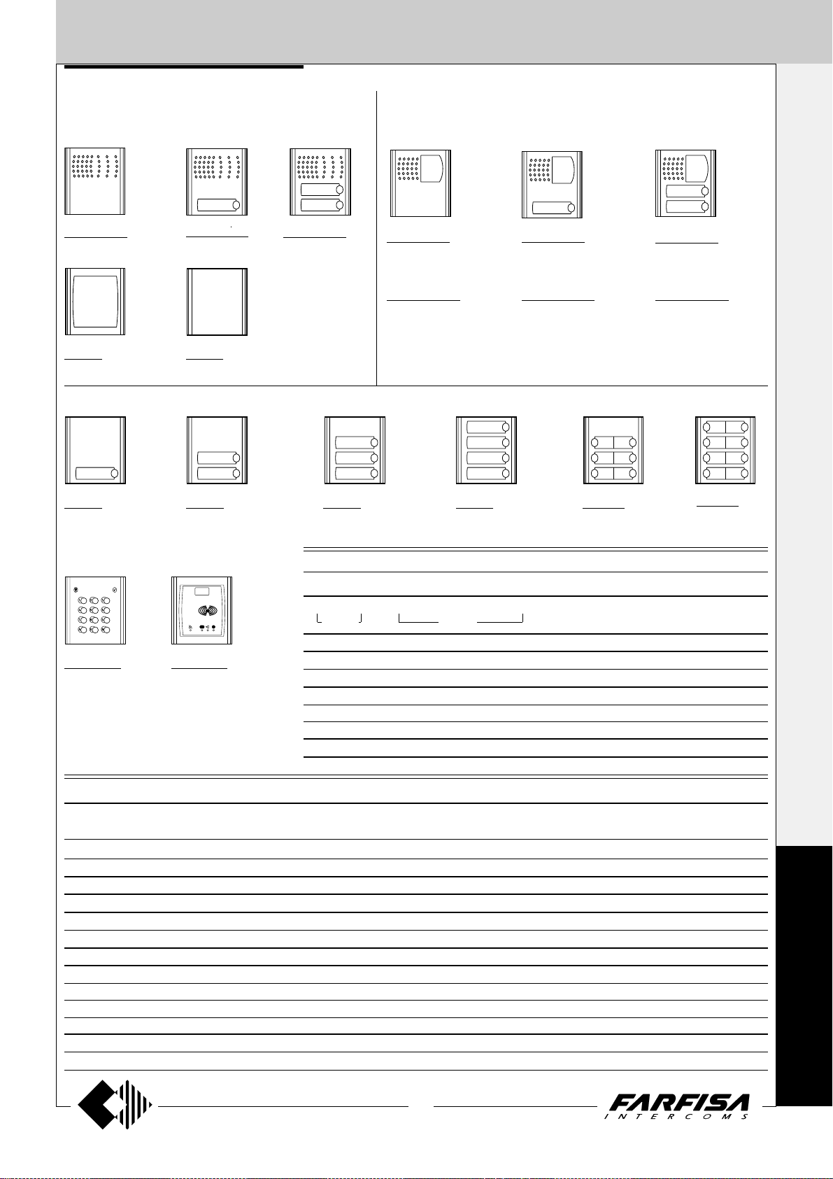
GENERAL CHARACTERISTICS
s
Exhito
Compact
Studio
Project
Agorà
Profilo
Matrix
Mody *
UP **
1+1 4+1 4+1 7+1
VIDEO-
INTERCOMS INTERCOMS
Serie
Internal stations
Echos *
External door stations
The Farfisa electronic call system with reduced
wires technology allows for the realisation of
intercom, video intercom and intercommunicating systems.
The modularity of Farfisa indoor and outdoor
devices allows for system extension to satisfy
the most diverse user’s requirements, from
individual houses to apartment buildings, from
simple intercoms to complete videointercoms.
Selecting the system
The first choice to be made is the preferred
type of system.
• Analog system with reduced number of
conductors (1+1 intercoms: 1 common
wire +1 wire for each user; 4+1 videointer-
coms: 4 common wires +1 wire for each
user).
• traditional analog system (4+1 intercoms:
4 common wires +1 wire for each user; 7+1
videointercoms: 7 common wires +1 wire
for each user + coaxial cable).
The Farfisa electronic call system allows for the
realisation of different types of installation.
• Intercom systems with 1 or more main
entrances and with or without secondary
entrances
• Videointercom systems with 1 or more
main entrances and with or without secondary entrances
• Intercommunicating systems
• Mixed systems (intercoms/videointer-
coms/intercommunicating systems)
• Intercom systems
It is the simplest of the installations. It provides
bidirectional audio communication between
intercoms and external door stations with dooropening function.
The following variants of the basic installation
are possible:
-intercommunicating service. It allows for
communication between different intercoms
of the same apartment or between different
apartments with private conversation to other
users and to external stations
-private conversation. By adding a board to
each intercom you can restrict the communication between internal and external user to
the called user. The other users do not hear
the conversation in progress when they lift the
handset.
• Videointercom systems
Apart from audio communication and dooropening function, video intercom systems provide visual control of the entrance.
The typical characteristics of video intercom
systems are:
-Timed operation. The video intercom of the
called user is enabled for about 100 seconds.
Picking-up the handset the enabling time will
be doubled; hanging up the handset the system switches back to the stand-by mode.
Systems which are using the power supplytimer art.1181E and 1281E switch back to the
stand-by mode only when the enabling time
expires.
-Private conversation. Video intercom systems allow for audio communication only for
the called user. The other users do not hear
the conversation in progress when they lift the
handset.
-Intercommunicating service. This service
allows for audio communication between different intercoms or video intercoms of the
same apartment or between different apartments with private conversation to other users
or external stations.
-Control switching ON. The user can enable
the system, switch ON his/her own video intercom and monitor the area framed by the camera. Additional wires and activation buttons
are needed in case of multiple entrances.
• Mixed systems (intercoms/videointer-
coms/intercommunicating systems)
All intercom and video intercom systems can
be combined according to the user’s requirements.
Selecting the articles
When choosing the article and type of installation, you should consider:
• user’s requirements
• number of users
• installation possibilities
• possible location of articles
The following options are possible for external
door stations and internal stations:
• External door stations:
- Agorà series
- Profilo series
- Matrix series (steel push-button panels)
- Mody series
- UP series
• Internal stations:
- Echos series
- Exhito series
- Compact series
- Studio series
- Project series
Table for the selection of house’s devices
and door stations according to the
performances of the system (see paragraph
“Selecting the system”)
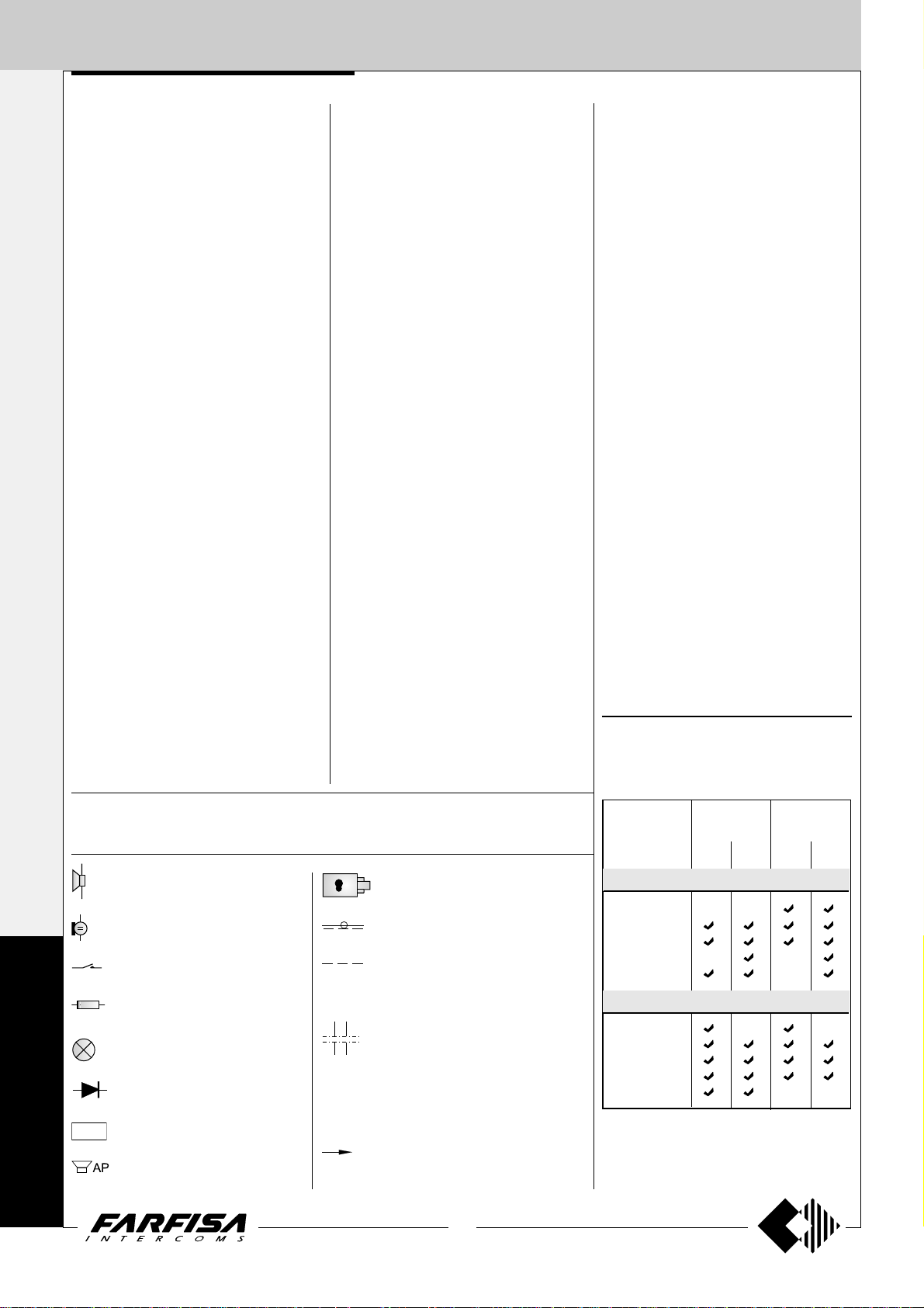
Graphic symbols
The following symbols are used in the installation diagrams:
Speaker
Microphone
Button
Resistance
Lamp
Diode
Electronic buzzer
SR41
Additional speaker
Electric door lock
Coaxial cable
Optional wire (usually control switching ON, door release button or intercommunicating calls)
Dashed line (for schematic purposes
the first and last monitors are shown in
the multi-family systems. Required
additional monitors can be inserted in
such dashed line to complete the installation).
xn
Call wires (second and last)
x2
2
(MT11 - Gb2012)
* For audio compatibility we do not suggest to
connect door stations MODY series with
internal devices ECHOS series.
** Series for up to 2 calls
Page 5

INTERCOMS AND VIDEOINTERCOMS SYSTEMS
REDUCED WIRES TECHNOLOGY
INDEX
Internal stations
- Echos series videointercoms
- Exhito series videointercoms
- Exhito series intercoms
- Compact series videointercoms
- Compact series intercoms
- Project series intercoms
External door stations
- Agorà series push-button p anels
- Profilo series push-button panels
- Matrix series push-button panels
- Mody series push-button panels
Power supplies
Service modules
Installation instructions
Working instructions
Installation diagrams
Page
4
4
9
11
14
15
15
16
16
22
31
38
47
47
50
52
53
3
(MT11 - Gb2012)
Page 6
INTERNAL STATIONS
XL+
F
EH9161
1181E
Orange
ECHOS SERIES
1+1
VIDEOINTERCOMS
INTERCOMS *
16
5
”
/
8
4+1
VIDEOINTERCOMS
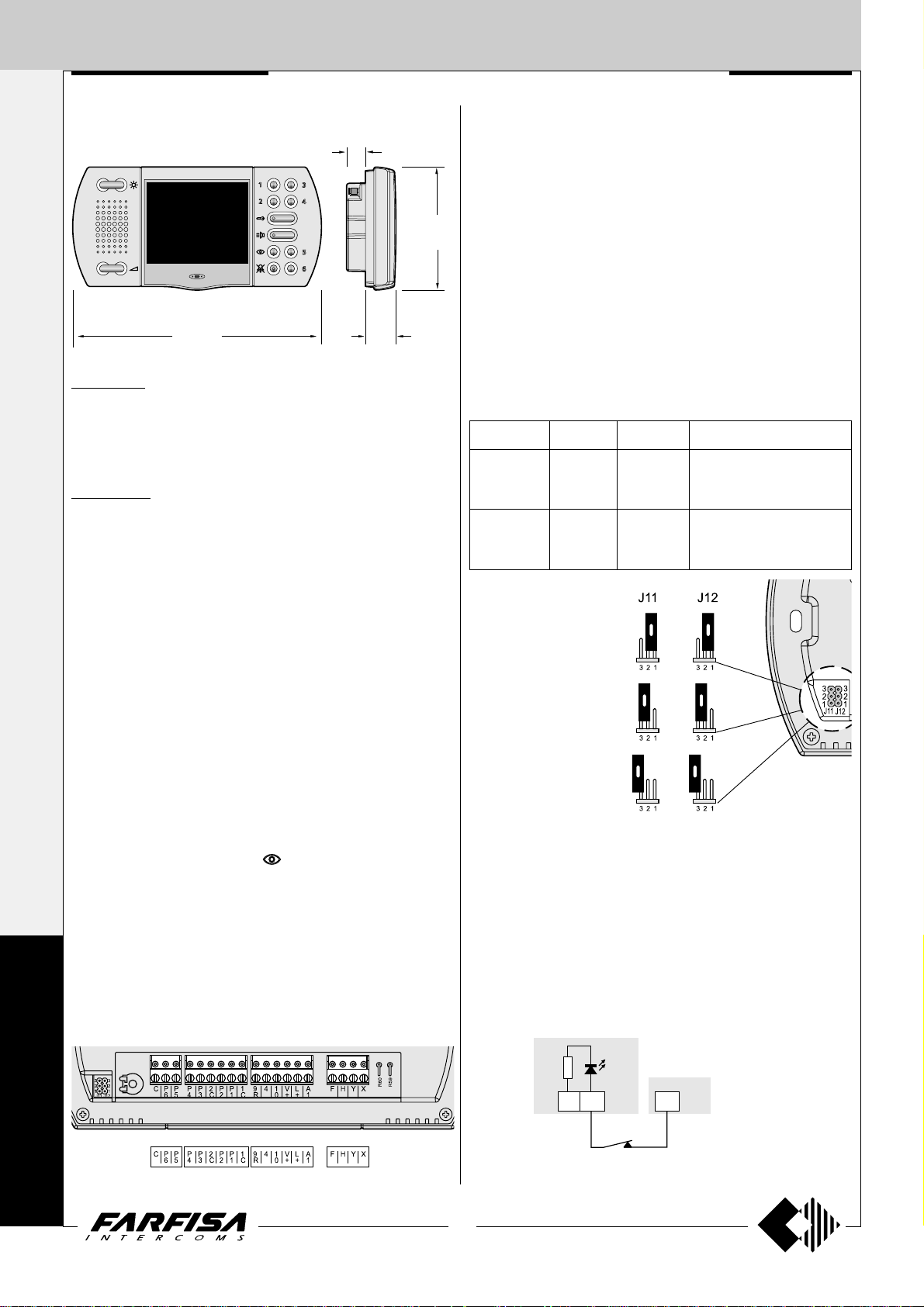
EH9161CT. Hands Free Colour Videointercom with audio-video
privacy, 3 types of calls, 5 differentiated programmable ring tones,
audio, contrast, and brightness adjustment. Metallized grey colour.
Complete with 10 keys for monitor control switching-on, door lock
opening, intercom calls and supplementary services. It can be installed
on the wall by using the back box art.9083 or wall adaptor WA9100T.
EH9161CW. Hands-free videointercom with same features as
above, in white colour finish. It can be installed on the wall by using the
back box art.9083 or wall adaptor WA9100W.
Technical characteristics
Power supply: 18÷24Vdc
Operating current: 0.4A
Screen: 3.5" LCD
Television standard: PAL
Horizontal frequency: 15625Hz
Vertical frequency: 50Hz
Band width: >5MHz
Video signal: balanced
Starting up time: 1 second
Number of bell rings: 2 (programmable)
Operating temperature: 0°÷+50°C
Maximum admissible humidity: 90%RH
208
8
3
”
/
16
26
1
How to select the function for buttons from 1 to 6
Buttons from 1 to 6 can be used for several functions, that is:
- intercommunicating calls;
- control switching ON of the video intercom when more than one
external door station or extra surveillance cameras are present on
the system;
- free voltage contacts for supplementary functions.
103
1
”
/
4
16
ATTENTION. The common contacts of the buttons are only two: one
for the buttons 1 and 2, the other for the buttons 3,4,5 and 6, so at
least only two of the three possible different operations described
before can be achieved at the same time. When the buttons are used
for intercommunicating calls or videointercom control switching ON
”
the terminals 1C and 2C must remain unconnected.
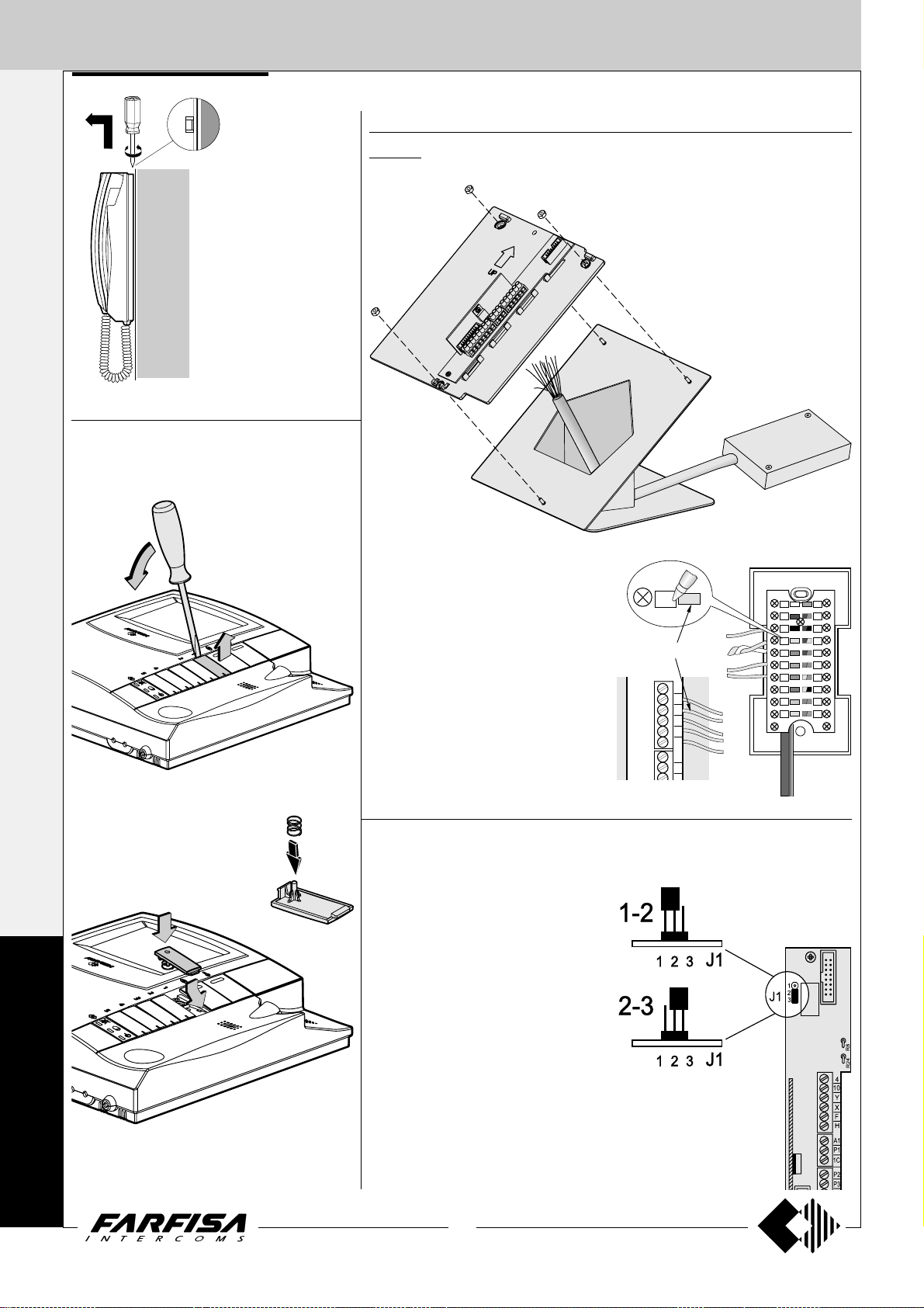
Functions of buttons according to the position of jumpers J11 and
J12
Push-buttons Jumpers Position Function
1-2 intercommunicating calls
1, 2 J12 2-3 (*) control switching ON
free free contacts (common 1C)
1-2 intercommunicating calls
3, 4, 5, 6 J11 2-3 (*) control switching ON
free free contacts (common 2C)
(*) Factory setting
1 - 2
Intercommunicating calls
2 - 3
Control switching ON
E
C
H
O
S
Terminals
X Balanced negative video signal input
Y Balanced positive video signal input
F Ground
H Positive voltage input (18-24Vdc)
10 Call, audio reception/transmission, door releasing
4 Control switching ON (button
9R Electronic call input from other intercommunicating devices
A1 Electronic floor call input
L+ LED for open-door signalling or other functions
V+ Positive voltage input for intercommunicating devices (15÷18Vdc)
1C Common contact for buttons P1 and P2
P1 - P2 Service buttons (max 50mA)
2C Common contact for buttons P3, P4, P5 and P6
P3 ÷ P6 Service buttons (max 50mA)
C Electronic call input for intercommunicating calls (common contact
for buttons P1÷P6 determined by the position of the jumpers J11
and J12)
)
Free
Free contacts commons 1C and 2C
Supplementary functions
Floor call
For floor call feature make the connection as reported on page 87.
Door-open’s warning and other functions
For door-open’s warning or other similar functions connect a normally
closed contact (NC) of a sensor or a relay between the terminal L+ of the
videointercom and terminal X of power supply 1181E .
Closed contact the orange LED is ON.
Open contact the orange LED is OFF.
4
(MT11 - Gb2012)
Page 7
INTERNAL STATIONS
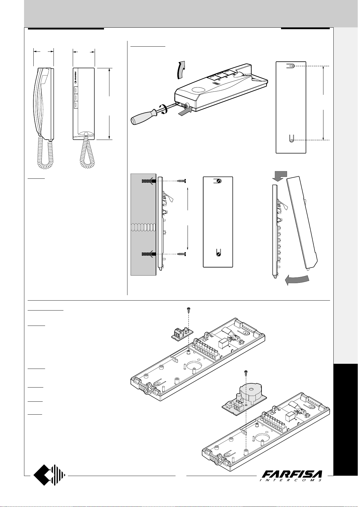
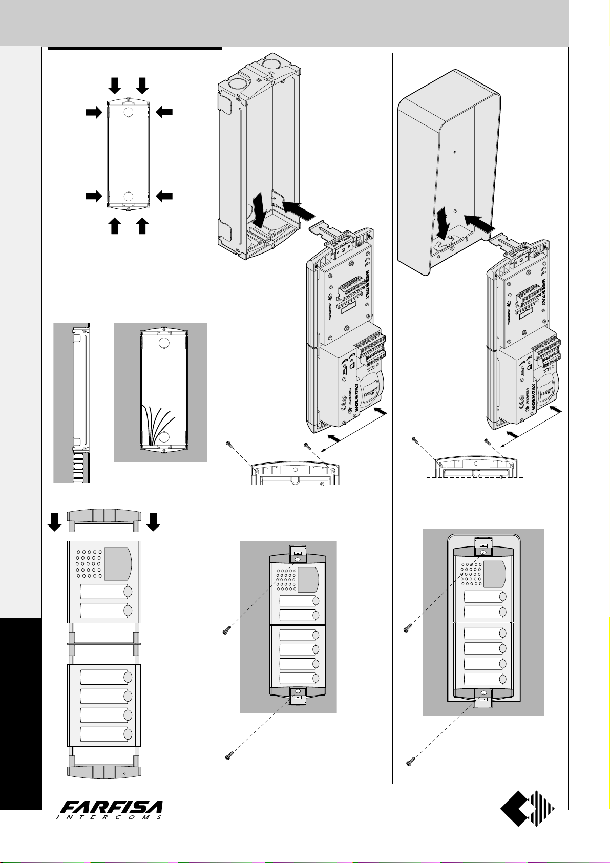
Flush mounted version
9083. Back-box for video intercoms
EH9161CT and EH9161CW.
4’ 11”
192
7
1+1
INTERCOMS *
92
3
46
13
”
/
1
16
5
”
/
8
4+1
VIDEOINTERCOMS
9
”
/
16
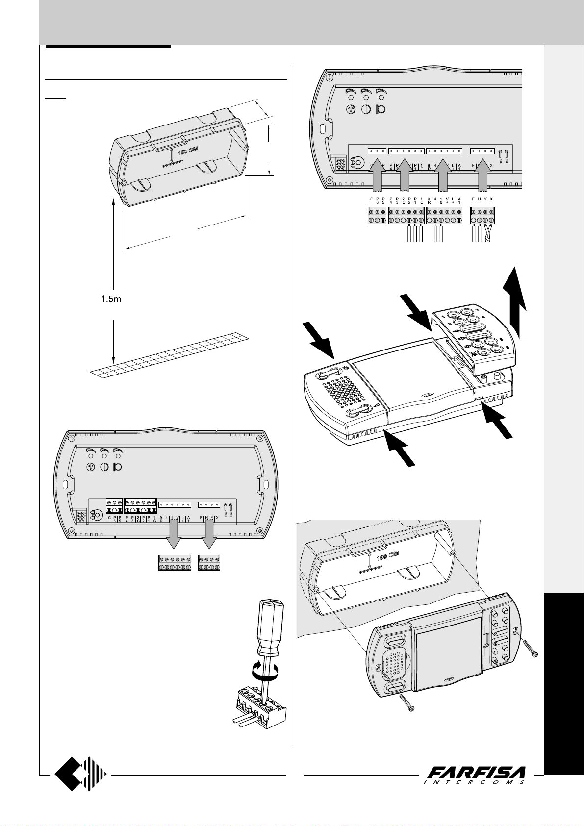
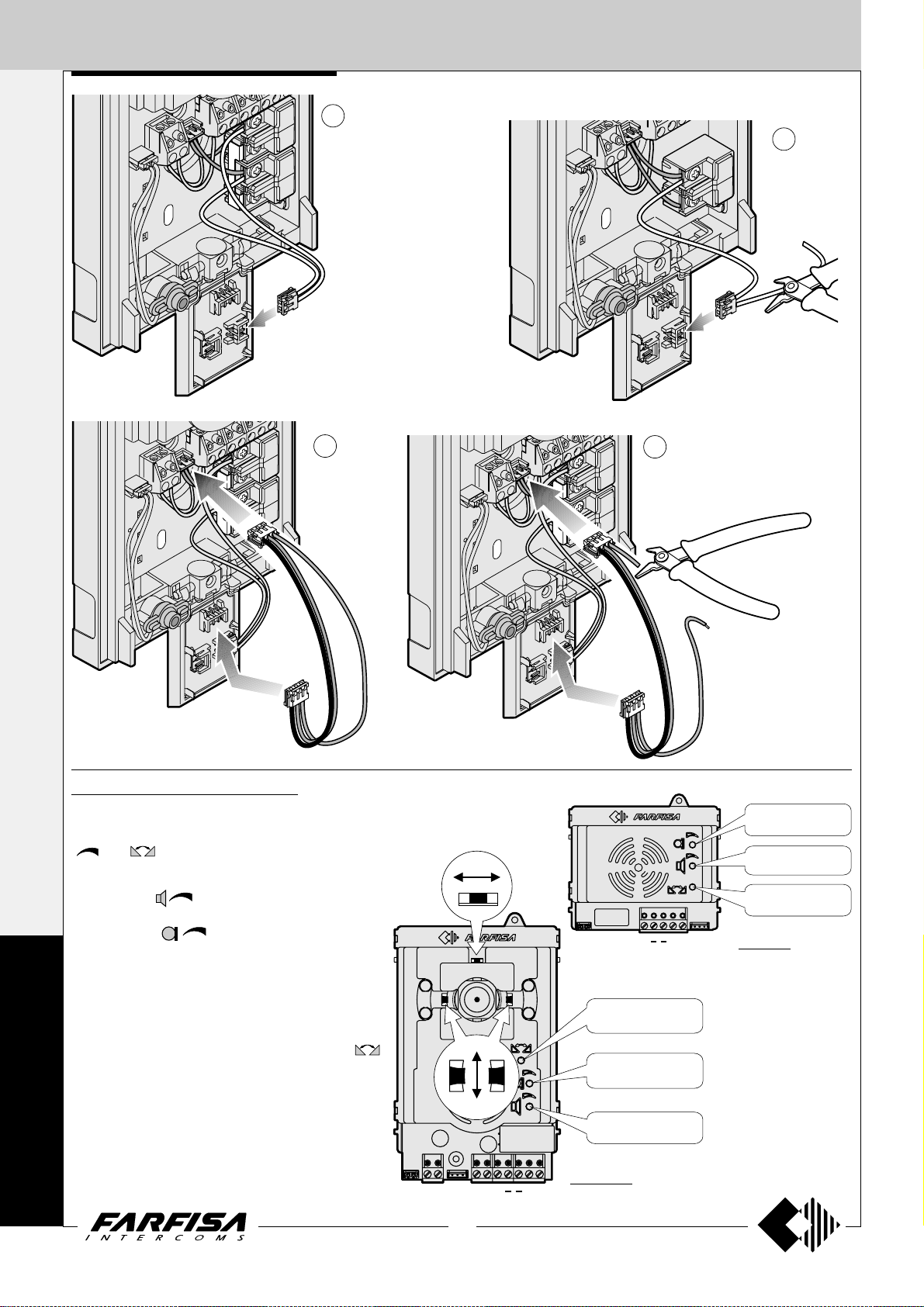
4 - Plug-in back the terminal blocks on the video intercom paying
attention to their position and direction in order to avoid degradation
of the system.
1 -Wall-up the back box art.9083 at an height of about 1.5 meters above
the floor.
2 -Unplug the terminal block from the video intercom.
5 -Remove the two frontal plastic frames to approach the two fixing
points of the video intercom.
E
C
H
3 -Make the connections as required by the elec-
tric diagram to wire. If the system provides for
the use of the buttons from 1 to 6, move the
jumpers J11 and J12, located on the back of
the video intercom, according to the required
function (see table on page 4).
O
S
6 -Fix the video intercom to the back box using the two screws supplied
with the product.
5
(MT11 - Gb2012)
Page 8
INTERNAL STATIONS
1+1
INTERCOMS *
4+1
VIDEOINTERCOMS
7 -Re-insert the two frontal plastic frames to the video intercom.
Surface mounted version
WA9100T. Wall adaptor for the EH9161CT videointercom.
WA9100W. W all adaptor for the EH9161CW videointercom.
Table version
TA9160. Table adapter for Echos videointercoms. Complete with
junction box and 2.4m connection cable with 20 wires.
WA9100T/W
TA9160
Junction box
1 -Fix the adapter to the wall with 4 expansion plugs at approx. 1.5m
from the floor.
E
C
X
Yellow
- Fix the wall adaptor
WA9100T or WA9100W
to the table adaptor using
the supplied nuts.
- Insert the cable in the
proper hole of the adaptor
and fix it.
- Make the connection on
the videointercoms
terminal boards and write
down the correspondence between terminals and wire’s colour on the
label on the junction box.
- Fix the videointercom as shown in the figure 2 of this page.
H
F
EH9161..
Y
X
Display adjustment
To optimize the angle of view of the display it can be adjusted up and
down for about 15°.
X
Y
H
O
S
2 -Fix the video intercom to the wall adaptor using the two screws
supplied with the product.
6
(MT11 - Gb2012)
Page 9
INTERNAL STATIONS
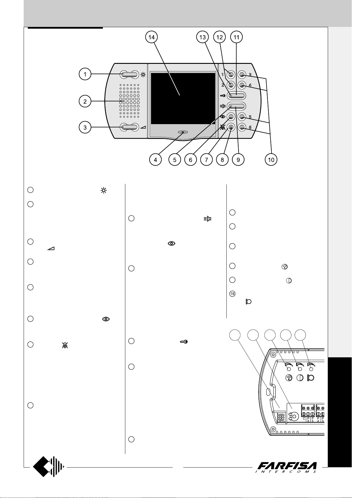
Characteristics
1+1
INTERCOMS *
4+1
VIDEOINTERCOMS
1
Image brightness adjustment .
2
Loudspeaker. It allows to hear the conversation and to receive the calls from the
external door station, from other intercommunicating equipments or from local door
station.
3
Call and communication volume adjust-
ment
4
Microphone. It allows to talk with the door
station or with other intercommunicating
equipments
5
Green LED. The LED shows:
- a communication in progress when it
lights up continuously;
- an intercommunicating call when it flashes.
6
Control switching ON button . It allows to power ON the video intercom and
monitoring the entrance.
7
Mute button . It allows to:
- enable/disable the audio (microphone)
to the door station during a conversation;
- enable/disable the bell rings if pressed
for less then 2 seconds after receiving a
call or making a control switching ON function;
- enter/exit the programming mode if
pressed for more than 2 seconds.
8
Red LED. The LED shows:
- temporary disabling of audio when it continuously lights-up. If audio is enabled again
the LED recover the previous operating
mode;
- bell rings disabling. The LED flashes
when a call is received and during the
.
conversation with an external door station
or another intercommunicating equipment;
- the videointercom is in programming operation mode when it is continuously lit-up.
9
Audio communication button . It al-
lows to enable the audio communication
with the door station or another intercom
after receiving a call or a control switching
ON operation (
cation is end pressing again the button or if
the communication time expires.
10
Buttons 3,4,5 and 6 are available for supple-
mentary services. After positioning properly the jumper J11 they can be used for:
- intercommunicating calls;
- control switching ON function for multiple
entrance systems;
- as free voltage contacts (max 50mA).
These four buttons, having a shared common contact (terminal 2C), can be only
used for one of the functions listed above at
time.
11
Lock release button . It allows to operate the electric lock release either with the
video intercom in ON or OFF state.
12
Buttons 1 and 2 are available for supplementary services. After positioning properly the jumper J12 they can be used for:
- intercommunicating calls;
- control switching ON function for multiple
entrance systems;
- as free voltage contacts (max 50mA).
These four buttons, having a shared common contact (terminal 1C), can be only
used for one of the functions listed above at
time.
13
Orange LED. The LED lights-up when at
the terminal L+ is connected a positive
voltage (8÷12Vdc). To signal an open-door
). The audio communi-
state it is necessary to install to the door a
proper sensor whose contacts must be a
normally closed type (see page 4).
14
3.5" Colour LCD Display.
15
Jumpers for programming buttons 1 to
6.
16
Microphone sensitivity adjustment
MIC.SENS.
17
Colour adjustment .
18
Contrast adjustment .
Adjustment of the microphone ampli-
.
fier
17 18 1915 16
E
C
H
O
S
7
(MT11 - Gb2012)
Page 10
INTERNAL STATIONS
1+1
ADJUSTMENTS
Brightness adjustment.
INTERCOMS *
With the video intercom switched ON, press
left and right the button
brightness of the image. T o store the current
setting press the button
this button switches OFF the video intercom.
Colour
4+1
The trimmers are located on the back of the
video intercom and can be operated by
means of a small screwdriver. T o adjust the
VIDEOINTERCOMS
trimmers is required:
-dismount the video intercom from the wall to
accede to the adjustment points;
-power ON the video intercom;
-insert the screwdriver in the hole marked
with the symbol of the adjustment required;
-rotate the screwdriver clock or anti-clock
wise to find the desired image quality;
-fix again the video intercom to the wall.
Enabling, disabling and volume of the
ringing sound.
When you receive a call from the door station
or from another intercommunicating
equipment it is possible to adjust the level of
the ringing sound pressing left and right the
button
the button
T o disable the ringing sound it is necessary,
during a receiving call, to press momentarily
the button
call and the conversation.
The status (enabled or disabled) and the level
of the ringing sound are stored and they are
used for next calls. If the ringing sound is
disabled during a receiving call or during a
communication the red LED will flash to
indicate this status, but no LED indication will
be present in stand-by mode. After connecting
a positive 15÷18Vdc to the terminal V+ it will
be possible to have the LED indication of the
disabled ringing sound also with the video
intercom in stand-by mode.
Setting of the audio volume
-With the video intercom switched ON, press
the button
E
C
H
O
S
T o set the receiving audio level (loudspeaker)
press left and right the button
the selected level press the button
pressure of this button switches OFF the
video intercom.
-To set the amplifier’s level of the microphone
it is necessary to adjust the trimmer
the back of the videointercom.
-In case of incorrect automatic switching of
the video intercom between talk and listening
function decrease the level of the preferred
function and increase the other one by
acting on the button
and Contrast adjustment.
. T o store the current setting press
.
; the red LED flashes during the
to enable the communication.
or on the trimmer
of the videointercom.
to adjust the
. The pressure of
. T o store
. The
on
-If required the communication the audio is
intermittent or distorted it is advisable to
adjust the microphone sensitivity by acting
on the trimmer MIC.SENS. located on the
back of the video intercom.
-Attention. For a better setting of the audio
levels on the video intercom adjust the
microphone sensitivity of the door station to
the minimum value and the loudspeakers
volume to an intermediate value.
- If there are intercommunicating devices
adjust also their audio levels.
PROGRAMMING
In programming mode it is possible to select
the duration and the ringer tone among 5
different possibilities.
T o enter the programming mode it is required:
-to switch ON the video intercom pressing the
button
-to keep pressed for more than 2 seconds the
buttons
operation and the red LED lights up.
Number of rings of the bell (external and
intercommunicating calls)
After entering the programming mode it is
necessary:
- to press the button
of the rings currently programmed;
- to press left and right the button
respectively increase or decrease the
number of rings. After each pressure of the
button the selected number of rings will be
heard;
- please keep the button pushed for more
than 2 seconds or wait for the end of the
programming time in order to make the
changes confirmed and exit from the operation.
Ringer tone selection (call from door station)
Once entering into programming mode, it is
necessary:
- to push the
ringer tone now programmed;
- to push laterally (left or right side) the
button to select the previous or next ringer
tone;
- after having selected the favorite ringer
tone, keep the
than 2 seconds or wait for the end of the
programming time to make the changes
confirmed and exit from the operation.
.
; a beep will confirm the correct
to verify the number
to
button in order to check the
button pushed for more
OPERA TIONS
Call from the door station
Making a call from the door station the video
intercom will ring (according to the
programming) or the red LED starts flashing
if the bell rings has been disabled; on the
display appears the image of the calling
station. T o start the communication press the
button
to the door station, but continuing hearing the
audio from the door station press shortly the
button
up continuously . To restore the audio to the
door station press again the button
red LED will recover the previous status. T o
end the communication and switch OFF the
video intercom press the button
video intercom switches OFF automatically
when the communication time expires or if
from the door station a call to another user is
made.
Control switching ON
The button
from 1 to 6, if present and correctly
programmed (see table on the page 4), allow
to display the images (without audio) of the
entrances presents in the system. T o get also
the audio it is sufficient to press the button
intercom.
Control switching ON is allowed only when the
system is in stand-by mode (no running
communications); if, pressing the control
switching ON buttons, the video intercom
doesn’t switch ON a communication between
another user and the door station could be
active.
Door lock release
To operate the electric door lock release
press the button
video intercom is switched ON or OFF .
If the system has more door stations the
electric door lock release of the door station
from which the last call has been made or to
which a control switching ON has been
directed will be activated.
. If it is desired to disable the audio
; in this status the red LED will light
; the
. The
and the buttons numbered
. Press it again to switch OFF the video
independently if the
8
(MT11 - Gb2012)
Page 11
INTERNAL STATIONS
EXHITO SERIES
VIDEOINTERCOMS
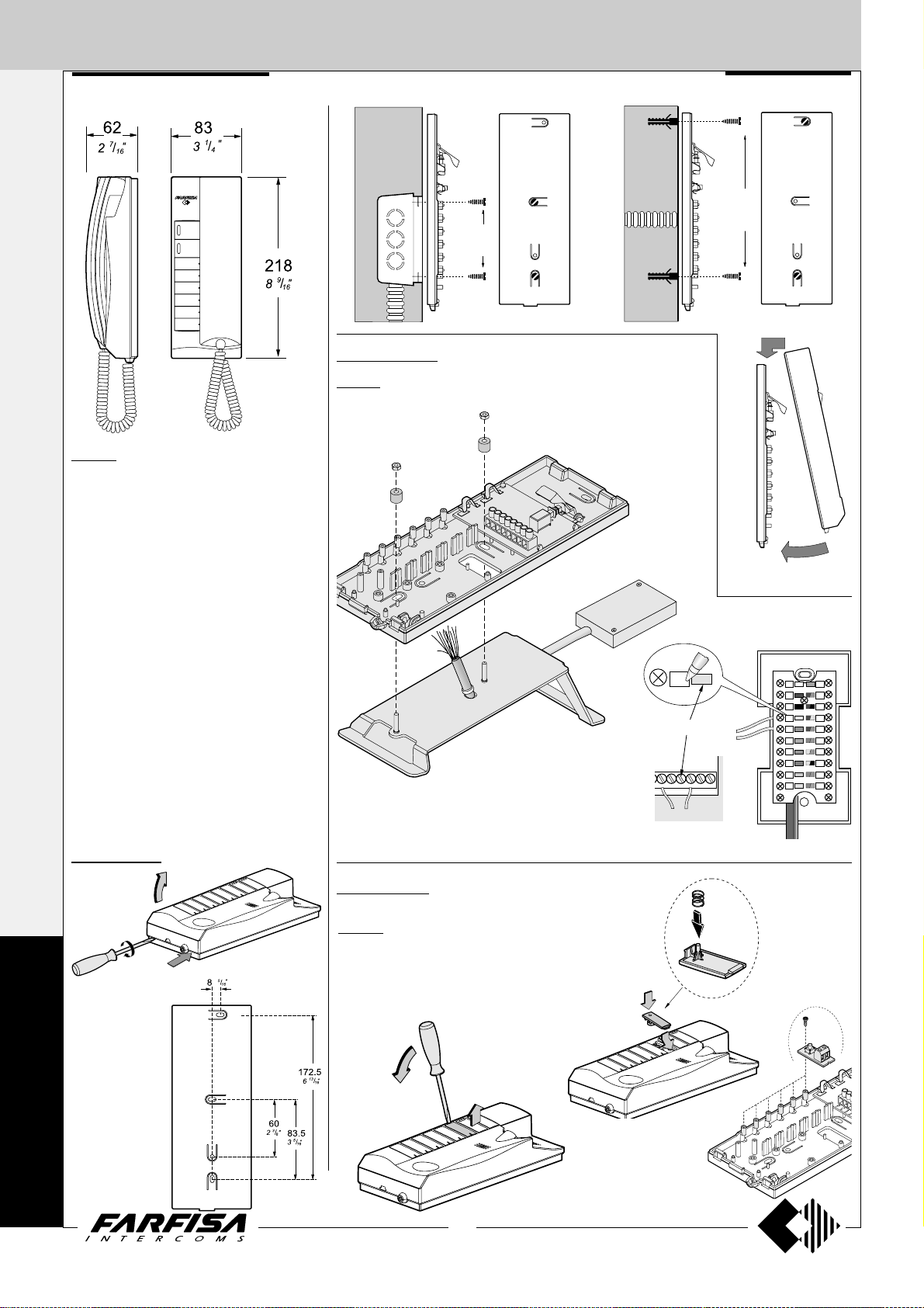
62
7
"
/
2
16
211
8
5
"
/
16
218
8
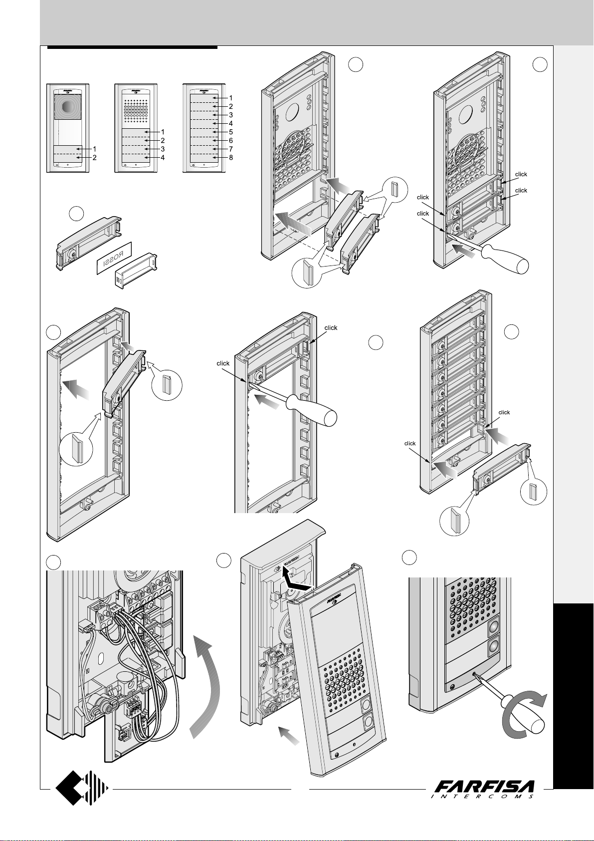
EX3160. White Flat videointercom with pri-
vate audio-video function, electronic microphone, differentiated double electronic ringing
sounds (modulated and continuous) and terminal board for the connection to the wall bracket.
Equipped with led's and 2 buttons for camera
control switch ON and door-open. Together
with the videointercom there are 5 extra buttons
which can be assembled in the proper slots
(see page 10).
The videointercom can be fixed to the wall
(flush-mounted) with the WB3161 bracket.
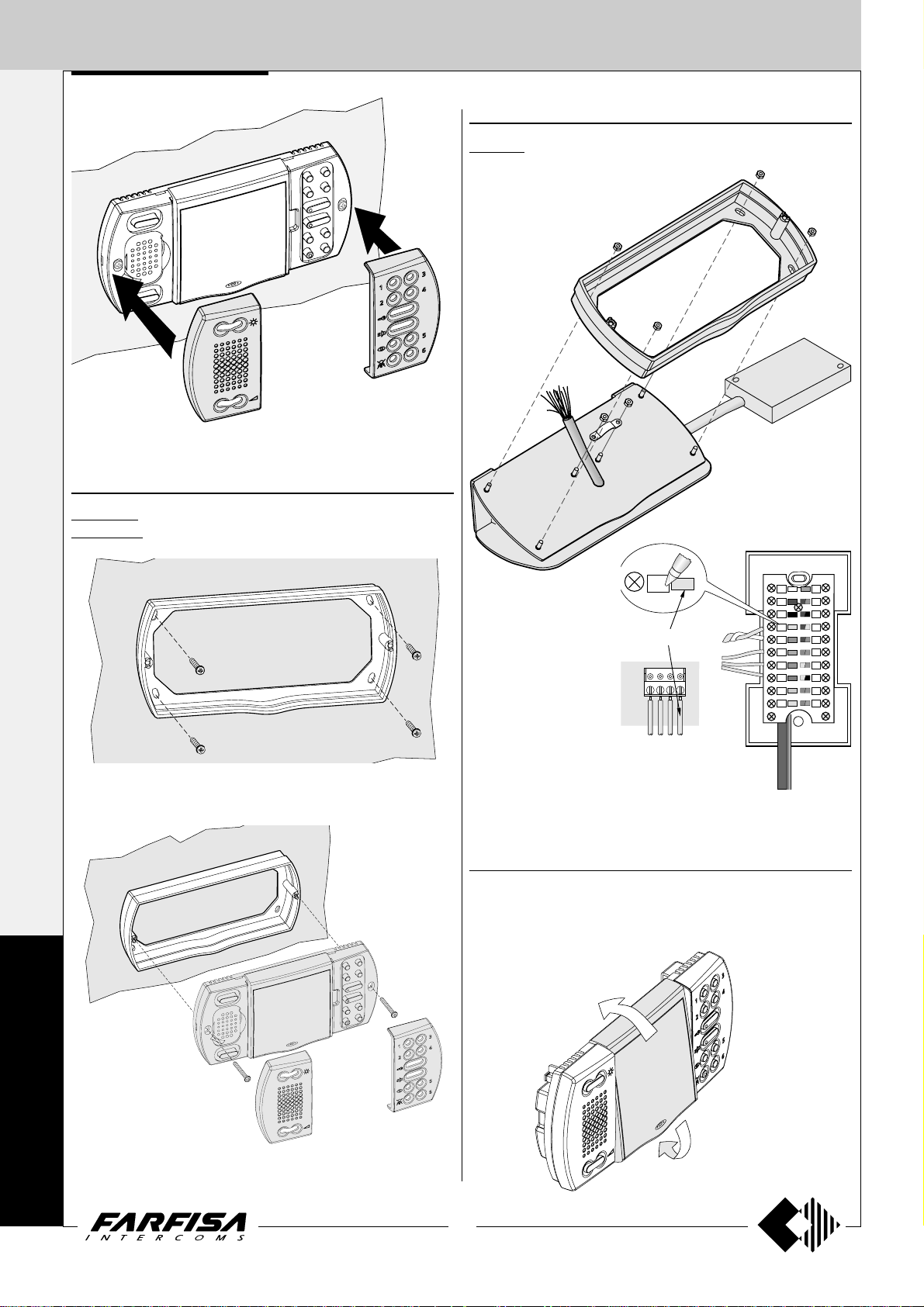
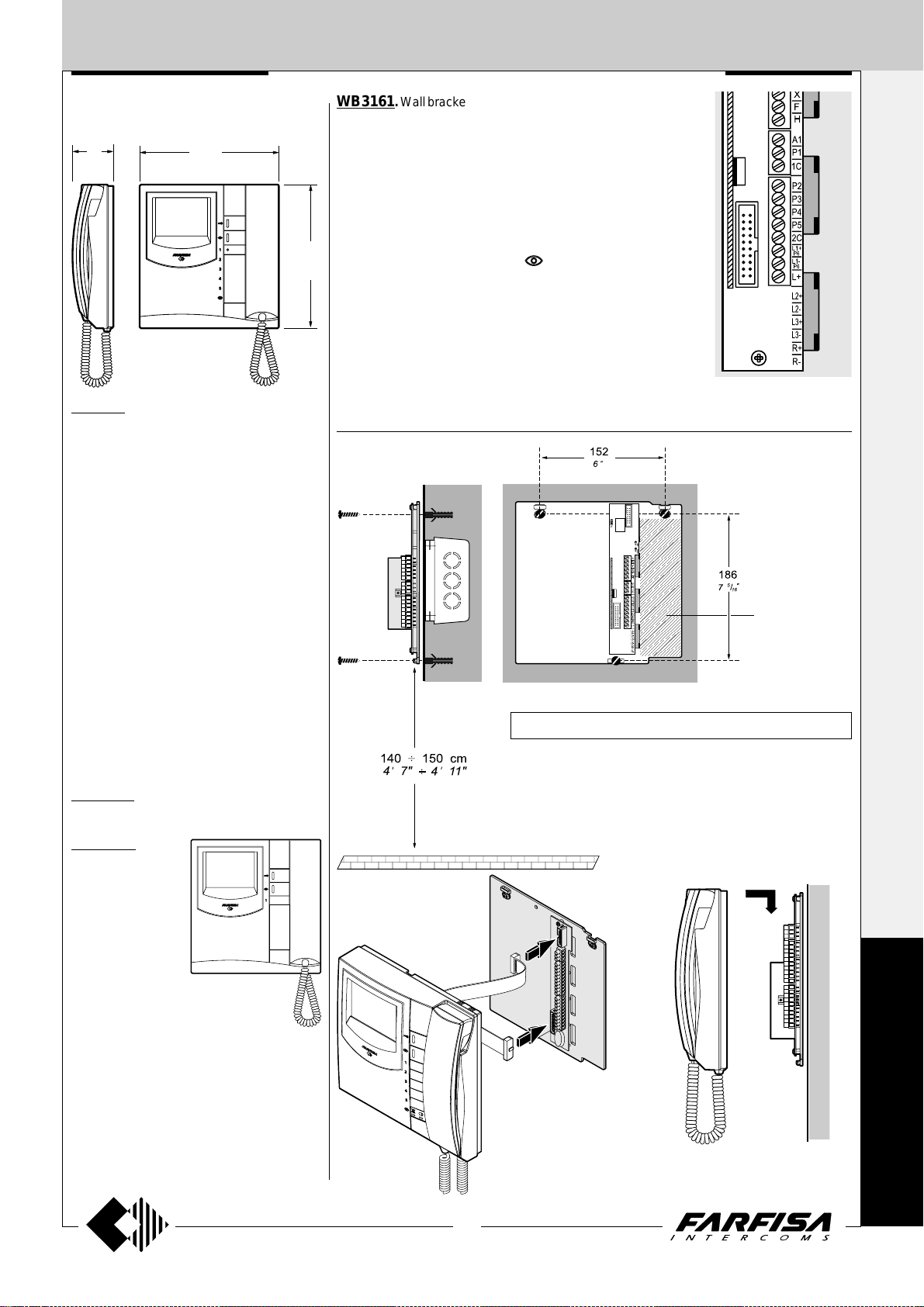
WB3161. Wall bracket for EX3100C, EX3160 and EX3160C video
intercoms with terminal boards for connection to the system and an
electronic circuit to convert the video signal from coax cable to a
balanced twisted pair.
Terminals
X Balanced negative video signal input
Y Balanced positive video signal input
F Ground
H Positive voltage input (+18-24Vdc)
10 Call, audio reception/transmission, door releasing
4 Control switching ON (button
9
"
/
16
A1 Electronic call input from other intercommunicating devices
1C Common contact for P1, P2, P3 (P2-P3 only for EX3160, EX3160C)
P1 Service button (max 0.3A)
P2 ÷ P5 (*) Service buttons (max 0.3A)
2C (*) Common contact for buttons P4 and P5
L1+ (*) Positive power supply input for red Led (+12Vdc)
L1- (*) Negative power supply input for red Led
L+ Not connected
(*) Not connected in EX3100C videointercom.
)
Wall version
1+1
INTERCOMS *
4+1
VIDEOINTERCOMS
Technical data
Power supply 12÷15Vdc
Operating current 0.4A
Monitor 4" FLAT CRT
TV standard CCIR-625 lines
Line frequency 15625Hz
Frame frequency 50Hz
Bandwidth >5MHz
Video signal on 75Ω 0.8÷1.5Vpp
Switching ON time 2 seconds
Operating temperature 0°÷+50°C
Maximum permissible humidity 90%RH
EX3160C. Version of EX3160 videointercom
with colour LCD.
EX3100C. It is dif-
ferent from the model
EX3160C because
of the lack of LED’s
and for the reduced
number of buttons
(only 3 for electrical
lock release, monitoring and supplementary functions).
Technical data
Power supply
12÷15Vdc
Operating current 0.4A
Screen 4" LCD
TV standard PAL
Line frequency 15625Hz
Frame frequency 50Hz
Bandwidth >5MHz
Video signal on 75Ω 0.8÷1.5Vpp
Switching ON time 1 second
Operating temperature 0°÷+50°C
Maximum permissible humidity 90%RH
-This area has to be free; remove possible present cables.
Fix the wall bracket by using 3 expansion plugs.
Don't shut the 3 screws of fixing if the wall is irregular.
It is suggested to use a wall box to contain the extra wires.
Plugging in of videointercom connectors to
the terminal boards of
wall bracket.
Installation of videointercom onto the wall bracket.
E
X
H
I
T
O
9
(MT11 - Gb2012)
Page 12
INTERNAL STATIONS
P1
10
Y
X
F
H
A1
1C
4
Yellow
Junction box
Y
Y
X
WB3161
1+1
INTERCOMS *
Installation of videointercom onto the
wall bracket.
4+1
VIDEOINTERCOMS
Assembling of extra buttons to the
videointercom EX3160 and EX3160C
Taking out of button caps
Table version
TA3160. Table adaptor with weighted base, junction box and 2.4m connection cable
with 20 wires.
Mounting of the additional buttons
E
X
H
I
Remove the cover to the junction box and
connect wires to the terminals matching the
colour of wire with that of the label. Write in
the proper space the code of the connection.
Choosing the private conversation or intercommunicating service
1-2 =Video intercom with-
out audio privacy
2-3 =Video intercom with
audio privacy
T
O
10
(MT11 - Gb2012)
Page 13
INTERNAL STATIONS
EXHITO SERIES
INTERCOMS
2
62
7
"
/
16
65
2
9
"
/
16
218
9
"
/
8
16
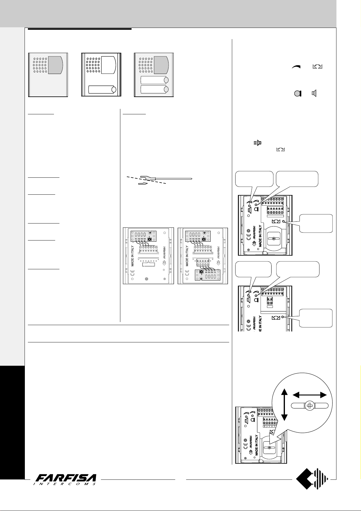
EX311. White electronic intercom with two
push-buttons, spiral cord, electronic microphone and possibility to insert an additional
EX301 push-button and a SR41 or SM50 mod-
ule. Wall-mountable with expansion plugs or
wall box.
Terminals
1 audio line, bell and door release control
3 ground
6 output electronic bell *
7 ground. Connected to terminal 3 with
jumper W1 *
A1 floor call or intercommunicating call input
P service push-button
C common contact for P push-button
Wall version
172.5
13
/
6
16
1+1
INTERCOMS *
172.5
13
"
/
6
16
4+1
VIDEOINTERCOMS
"
* terminals to be used when installing the pri-
vate conversation module SM50 in the inter-
com.
Accessories
EX301. Single button module for Exhito
intercoms. Maximum contact current is 0.1A.
For higher currents use a relay.
Note. For easier reference the 2 terminals of
the module are defined as C and P, but they
have no polarity and can be inverted.
EX304. Additional loudspeaker module
(*).
RL 36. Relay module (*).
SM50. Private conversation module (*).
SR41. Electronic buzzer module (*).
(*) for the connections and the characteristics
of the modules refer to page 13.
EX301
SR41 or
RL36 or
SM50 or
EX304
P
C
3
3
7
E
X
H
I
1
6
A1
T
O
11
(MT11 - Gb2012)
Page 14
INTERNAL STATIONS
A161733CP
EX321
Yellow
Junction box
1
1
3
INTERCOMS
1+1
INTERCOMS *
4+1
VIDEOINTERCOMS
EX321. White colour intercom for 1+1 inter-
com systems and intercommunicating systems
connected to 1 or more external door stations.
Complete with spiral cord, electronic microphone and 2 buttons extendable to 8 by adding
the EX301 single button module.
Possibility of inserting modules EX304, EX332,
SR41, RL36 and SM50.
Wall-mountable with expansion plugs or wall
box or on the desk using the table adaptor
TA320.
Terminals
1 audio line, bell and door release control
3 ground
6 output electronic bell *
7 ground. Connected to terminal 3 with
jumper W1 *
A1 floor call or intercommunicating call input
P service push-button
C common contact for P push-button
* terminals to be used when installing the
private conversation module SM50 in the inter-
com.
83.5
1
"
/
3
4
Table version
TA320. T able adaptor with weighted base, junction box and 2.4m
connection cable with 20 wires.
Remove the cover of the junction
box and connect wires to the terminals matching the colour of wire with
that of the label. Write in the proper
space the code of the connection.
EXHITO SERIES
172,5
13
"
/
6
16
E
X
H
I
T
O
Wall version
Accessories
EX301. Single button module for Exhito in-
tercoms. Maximum contact current is 0.1A. For
higher currents use a relay.
Note. For easier reference the 2 terminals of the
module are defined as C and P, but they have no
polarity and can be inverted.
12
(MT11 - Gb2012)
Page 15
INTERNAL STATIONS
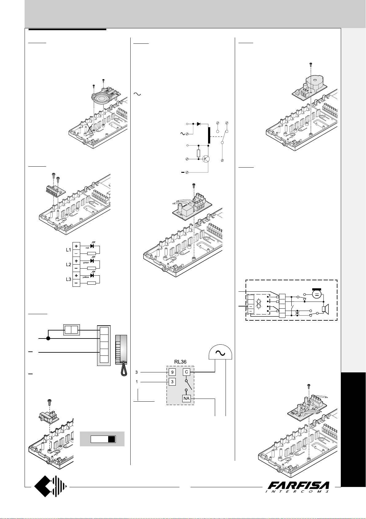
EX304. Additional loudspeaker. It allows
to receive calls with off-hook handset, or in
systems with 2 calls, with 1 single call and 1 call
in common to other intercoms.
To install the module the last module holder on
the intercom base must be removed (see drawing). The article
takes the space
of 2 modules and
therefore reduces the number of additional
buttons to 4.
EX332. Module with 3 LED.
RL 36. Relay module. When installed inside
intercoms it allows to activate additional bells.
Maximum switching current is 1A (24V).
Terminals
C common terminal of relay
NA normally open contact of relay
NC normally closed contact of relay
- ground
13Vac/dc voltage input
EC relay activation input (ground command)
Wires
9 electronic call in-
put without resistive load
3 ground
9
3
EC
NA
NC
C
SR41. Electronic buzzer module. In the
intercoms can be added for having a further call
signal.
Terminals
4 power supply input
(13Vac-70mA; 9÷20Vdc-15mA)
3 ground
SM50. Private conversation module.
To have complete audio privacy between users it is necessary to add to each intercom the
private conversation module.
The intercom can communicate with the outside (for an unlimited period) only after having
received the call. The intercom becomes
disactived when there is a call from another
intercom or the door release push-button is
pressed.
1+1
INTERCOMS *
4+1
VIDEOINTERCOMS
L1, L2, L3
terminals input + / - : max 13Vac / 24Vdc
ST703. Ringing volume adjustment
switch.
C
9
P
P = audio and call conduc-
tor
= ground conductor
Note
Do not use this connection
in intercoms where is
already installed the module
SM50.
A1
6
1
3
7
EX321
Additional bell connection
If the ringing volume is not sufficient or if you
need to chime the call in a different place, you
can add an additional bell enabled by a relay.
intercom
terminals
13÷48Vac/dc
Terminals
C audio line receiver
B audio line transmitter
- ground
Note
B and C terminals are unused in an 1+1 intercom
system.
CT
C
B
R1
Notes
In each intercom EX311 or EX321 it is neces-
sary:
- to cut the jumper (W1) that links the terminals 3 and 7;
- to make the connection between terminal 7 of
the intercom and the - (minus) of the private
conversation module.
In all SM50 private conversation modules cut
the resistance R1.
EX311 + SM50
EX321 + SM50
1
6
2
3
1
6
3
7
W1
E
X
H
I
OFF MED. MAX.
3 levels to adjust ring-
ing volume (off, me-
dium and maximum)
T
O
13
(MT11 - Gb2012)
Page 16
INTERNAL STATIONS
1+1
VIDEOINTERCOMS
88
7
"
/
INTERCOMS *
229
"
9
3
16
4+1
VIDEOINTERCOMS
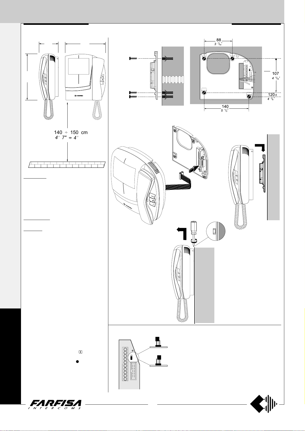
140 150 cm÷
47"
COMPACT SERIES
201
15
"
/
7
16
11"
4
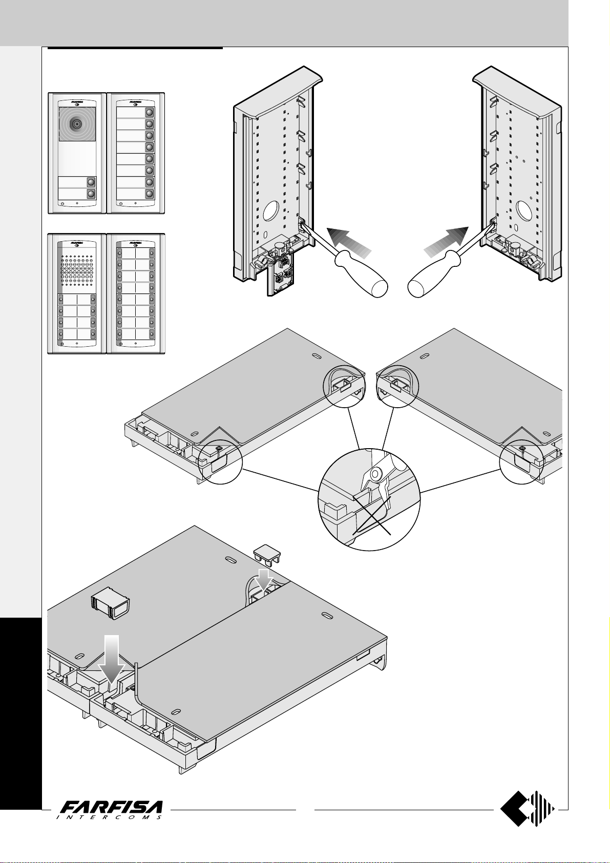
Installation
Fix the wall bracket by using 4 expansion plugs
KM8111W. White flat video intercom with
two buttons, one for control switch ON and one
for door lock release, audio-video privacy, electronic microphone, electronic modulated call
note, terminal board for the connection to the
wall-bracket. It can be installed on the wall (with
no built-in) by using the art.WB8111.
KM8111CW. Version with colour LCD.
WB8111. Wall-bracket for the KM8111W
and KM8111CW video intercoms. It includes a
terminal board for connection to the system.
Technical data
Power Supply 18÷24Vdc
Operating current 0.5A
Video tube (KM8111W) 4" FLAT CRT
Screen (KM8111CW) 4" LCD
Television standard (KM8111W) CCIR-625 lines
Television standard (KM8111CW) PAL
Horizontal frequency 15625Hz
Vertical frequency 50Hz
Bandwidth >5MHz
Video signal balanced
Starting up time (KM8111W) 2÷4 seconds
Starting up time (KM8111CW) 1 second
Operating temperature 0°÷+50°C
Max. permissible humidity 90%RH
C
Terminals
H Positive power supply input 18÷24Vdc-0.5A
F Ground
O
X and Y Video signal input
10 Call, audio reception/transmission, door re-
M
P
leasing
4 Control switch ON - button
A1 Floor call input
PC - P Service push-buttons
A
C
(max 0.3A)
Plugging in of videointercom connectors to the terminal boards of wall
bracket.
Dismounting of videointercom from the wall bracket.
Choosing the private conversation
A
X
Y
3
A1
2
1
J1
F
F
H
10
4
P
PC
123
123
J1
1-2 = Videointercom with-
B
J1
2-3 = Videointercom with
Installation of videointercom onto the wall
bracket.
out audio privacy
audio privacy
T
14
(MT11 - Gb2012)
Page 17
INTERNAL STATIONS
3
"
16
/
1
2
8
"
"
16
16
/
/
13
1
77.572
214
COMPACT SERIES
PROJECT SERIES
INTERCOMS
2
65
9
"
/
16
3
86
3
"
/
8
211
5
"
/
8
16
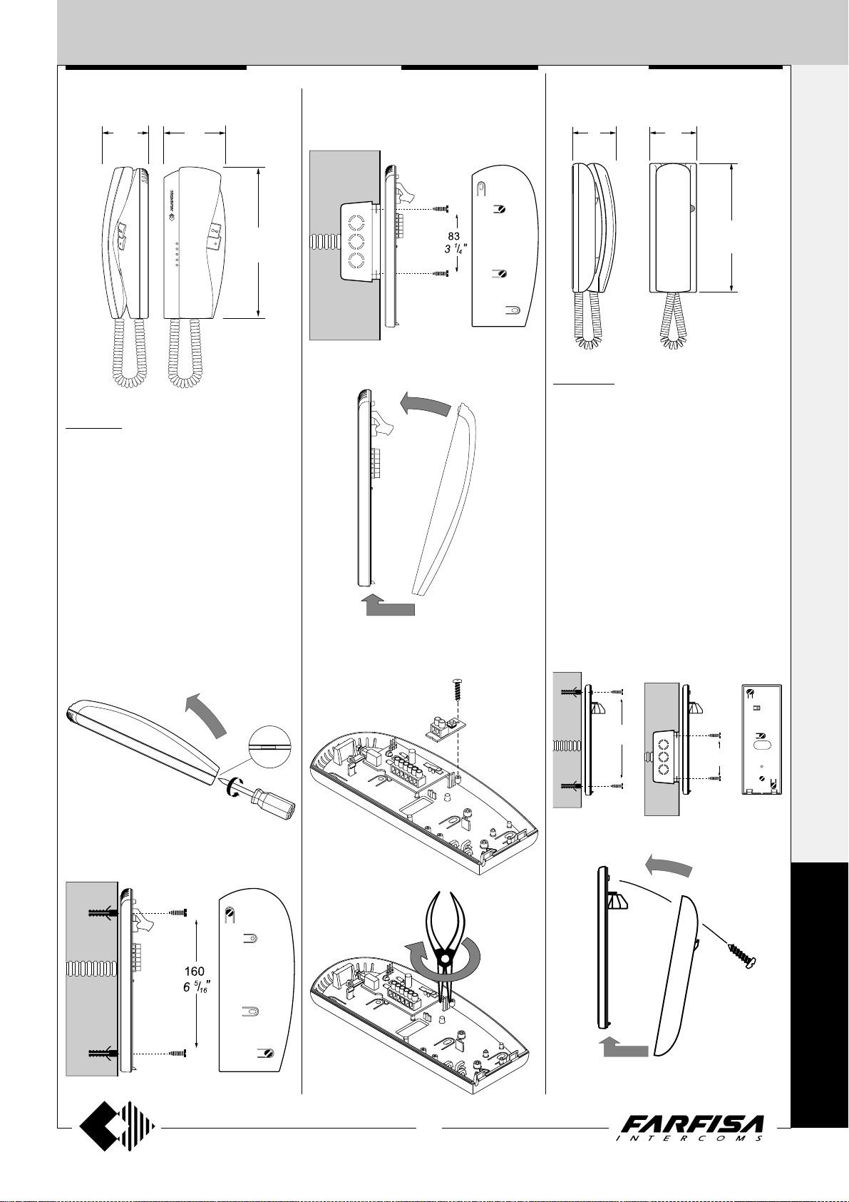
KM811W. White electronic intercom with 1
push-button, spiral cord, electronic microphone
and possibility to insert an additional ST701
push-button and a SR41 or SM50 module
(description and characteristics of the modules on page 13). Wall-mountable with expan-
sion plugs or wall box.
Terminals
1 audio line, bell and door release control
3 ground
6 output electronic bell *
7 ground. Connected to terminal 3 with jumper
W1 *
A1 floor call input
INTERCOMS
PT511EW. White electronic intercom with 1
push-button, spiral cord, electronic microphone
and possibility to insert SR41 or SM50 module
(description and characteristics of the modules on page 13). Wall-mountable with expan-
sion plugs or wall box.
Terminals
1 audio line, bell and door release control
3 ground
6 output electronic bell *
7 ground. Connected to terminal 3 with jumper
W1 *
A1 floor call input
* terminals to be used when installing the private
conversation module SM50 in the intercom.
1+1
INTERCOMS *
4+1
VIDEOINTERCOMS
* terminals to be used when installing the private
conversation module SM50 in the intercom.
Mounting of the additional button ST701.
ST701
182
7
3
"
/
16
83
1
"
/
3
4
K
M
P
T
15
(MT11 - Gb2012)
Page 18
EXTERNAL DOOR ST ATIONS
External door station
1+1 INTERCOMS * 4+1 VIDEOINTERCOMS
30
1
3
/
16
"
208
8
99
"
7
8
/
3
3
"
/
16
AG100A. Audio Door Station composed of an
ABS box for surface mounting, front plate in aluminium and electronic board with diodes and LED’s
for lighting the nameplates. Suitable for the AG30ED
door speaker and maximum 4 AG21 single pushbuttons or 4 AG222 double push-buttons.
AGL100A. Light grey version.
Surface mounting Door Stations
with reduced width and thickness.
Installation is easy and quick
because no recessed box is
required. Front plate is in extruded
anodized aluminium. Name plates
are backlighted with blue LED’s
for a better reading even in dark
places. Reduced dimensions and
surface mounting features make
the product particularly suitable
for the installations on the entry
gate’s post.
x 1
x 4
x 1
AGORA' SERIES
AG20. Blank module
AGL20. Light grey version.
AG21. Single button module with name plate
holder.
AGL21. Light grey version.
AG222. Double button unit with name plate
holder.
AGL222. Light grey version.
AG30ED. Audio Door Speaker to fit inside
the Door Stations AG100A and AGL100A.
Terminals
A Alternated power supply input for audio and
name-plate Led (13Vac-0.1A)
- Ground
1 Reception-transmission / door releasing / call
S Electric lock
A
G
O
R
À
AG100V. Video Door Station composed of an
ABS box for surface mounting, front plate in aluminium and electronic board with diodes and LED’s
for lighting the nameplates. Suitable for AG40CED
colour camera with door speaker and maximum 2
AG21 single push-button or 2 AG222 double push-
buttons.
AGL100V. Light grey version.
x 1
x 2
x 1
AG100T. Push-buttons Door Station com-
posed of an ABS box for surface mounting, front
plate in aluminium and electronic board with diodes
and LED’s for lighting the nameplates. Suitable for
8 AG21 single push-button or 8 AG222 double
Push-buttons.
AGL100T. Light grey version.
x 2
x 8
AG40CED. Colour camera with integrated door speaker to fit
inside the Door Stations AG100V and AGL100V.
Technical data
Video power supply 18÷24VDC-0.21A
Audio power supply 13VAC-0,15A
Video signal output balanced
Video signal standard PAL
Minimum lighting 2.5 Lux
LED's 4 white
Sensor CCD 1/3"
Number of pixel 291,000
Lens 3.6mm
Focusing 0.6m ÷ ∞
Horizontal/vertical sweep ±10°
Operating temperature -10° ÷ +40°C
Maximum permitted humidity 80% RH
Terminals
H Positive voltage input for camera (18÷24Vdc)
F Ground
X Balanced negative video signal output
Y Balanced positive video signal output
A Alternated power supply input for audio and name-plate Led (13Vac)
- Ground
1 Reception-transmission / door releasing / call
S Electric lock
16
(MT11 - Gb2012)
Page 19
EXTERNAL DOOR STA TIONS
Installation and Assembly of AGORA’ door stations.
1
2a
AG100V
AGL100V
AG40...
2b
AG100A
AGL100A
AG30...
1+1
INTERCOMS *
4+1
VIDEOINTERCOMS
3a 3b
AG100V
AGL100V
max.2
AG100A
AGL100A
max.4
3c
AG100T
AGL100T
max.8
A
G
O
R
17
(MT11 - Gb2012)
À
Page 20
AS1
Anti-feedback (Larsen
effect) adjustment
Receiver adjustable
volume (loudspeaker)
Transmitter adjustable
volume (microphone)
EXTERNAL DOOR ST ATIONS
1+1
INTERCOMS *
4+1
VIDEOINTERCOMS
4a
The wires of connection
cable must be connected
to the calling terminal (not
to the common terminal)
5a
4b
.
Cut and keep insulated not
used wire.
5b
Adjustments AG30ED and AG40CED
Adjustments are carried out in the factory; should any be
necessary they can be re-adjusted from the outside with a
screwdriver with the trimmers identified by the symbols
"
" and .
Adjustment of volume
Rotate trimmer
ing channel (loudspeaker).
Rotate trimmer
transmitting channel (microphone).
Anti-feedback adjustment
A
- Make a call from the door station and pick up the handset
G
O
R
À
of one of the videointercoms.
- Remove the microphone from its housing inside the
push-button panel, place it on the loudspeaker of the
electric door answering system and adjust the
trimmer until the feedback stops (Larsen effect).
- Replace the microphone in its housing.
Sweeps
If necessary, you can manually change the camera framing
by adjusting the horizontal and vertical levers in the desired direction (see figure).
to change the volume of the receiv-
to change the amplification of
±10°
±10°
HXASFY1
18
(MT11 - Gb2012)
Anti-feedback (Larsen
effect) adjustment
Transmitter adjustable
volume (microphone)
Receiver adjustable
volume (loudspeaker)
AG40CED
"E" terminal.
Cut the red wire to get "E"
terminal only if required by
the installation diagram.
AG30ED
Page 21
EXTERNAL DOOR STA TIONS
ASSEMBLY MODULE SEQUENCE
Insert the Push-buttons or blank modules starting
from the top of the frontal plate
6
AG21
AG222
AG100T
AGL100T
7b
AG20
AG21
AG222
AG100T
AGL100T
7a 8a
AG100V
AGL100V
AG100A
AGL100A
AG20
AG21
AG222
AG100T
AGL100T
8b
AG100V
AGL100V
AG100A
AGL100A
9b
1+1
INTERCOMS *
4+1
VIDEOINTERCOMS
10
11
12
A
G
O
R
À
19
(MT11 - Gb2012)
Page 22
EXTERNAL DOOR STA TIONS
1+1
ASSEMBLING DOOR STA TIONS SIDE BY SIDE
INTERCOMS *
AG100V
AGL100V
AG100A
AGL100A
AG100T
AGL100T
4+1
VIDEOINTERCOMS
Remove the side plastic caps
(only from the interested side)
to insert the spacers.
AG100V
AG100T
AGL100T
AGL100V
AG100A
AGL100A
A
G
O
R
À
AG100T
AGL100T
AG100V
AGL100V
AG100A
AGL100A
20
(MT11 - Gb2012)
Page 23
EXTERNAL DOOR STA TIONS
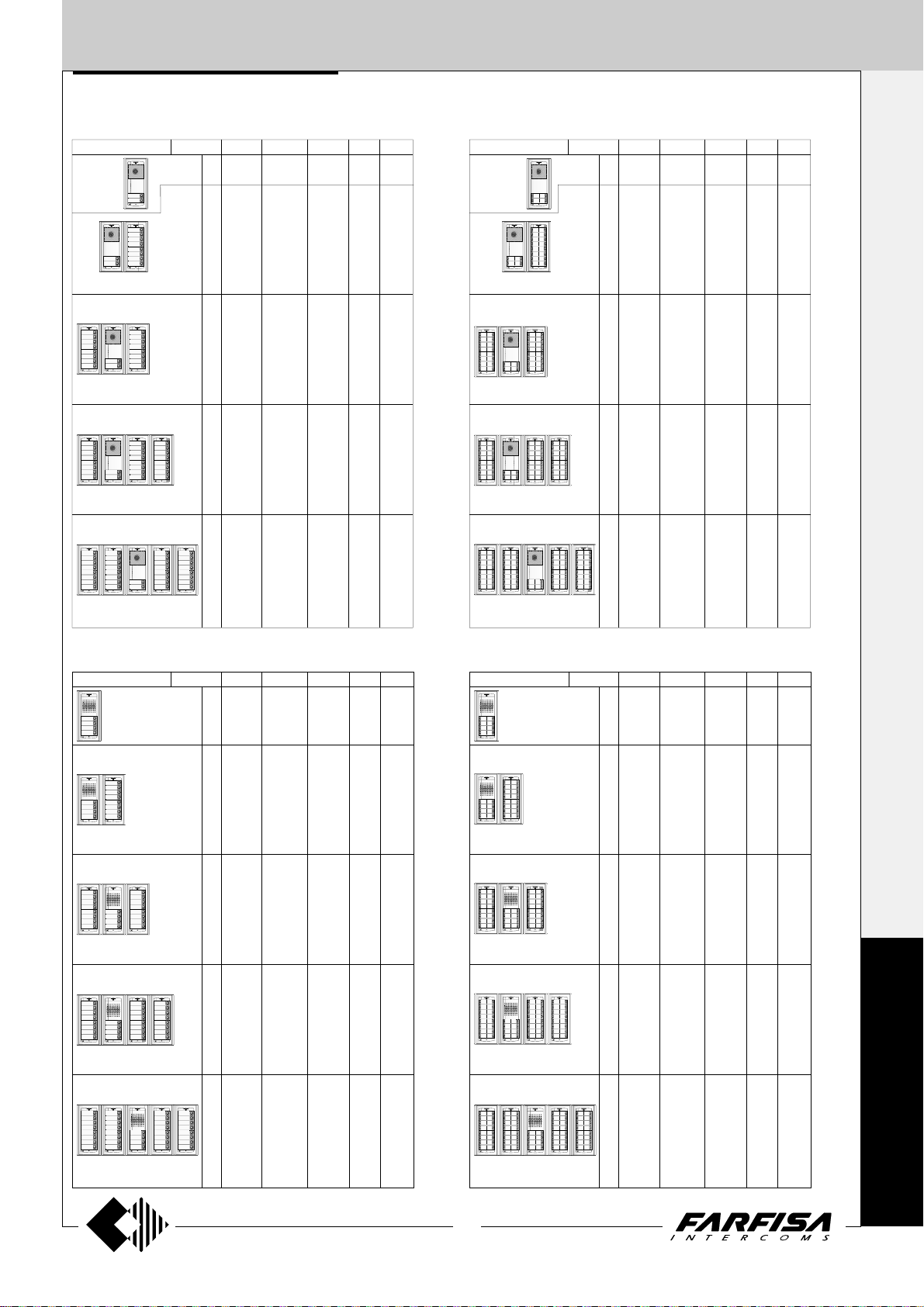
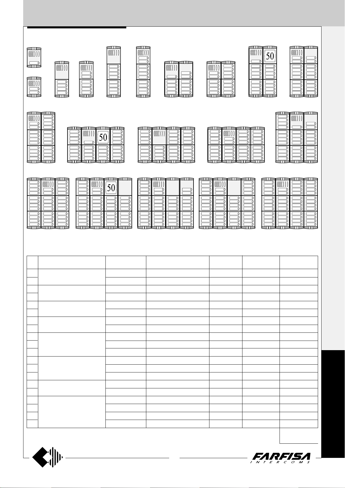
Composition of door stations and requested quantities of modules
1 ROW VIDEOINTERCOM push-button panels 2 ROW VIDEOINTERCOM push-button panels
AG100V AG100T AG20
N. buttons
AG40CED
1
1
2
3
4
5
6
7
8
9
10
11
12
13
14
15
16
17
18
19
20
21
22
23
24
25
26
27
28
29
30
31
32
33
34
1
1
1
1
1
1
1
1
1
1
1
1
1
1
1
1
1
1
1
1
1
1
1
1
1
1
1
1
1
1
1
1
1
1
1
1
1
1
1
1
1
1
1
1
1
1
1
1
1
1
1
1
1
1
1
1
1
1
1
1
1
1
1
1
1
1
1
-
-
1
1
1
1
1
1
1
1
2
2
2
2
2
2
2
2
3
3
3
3
3
3
3
3
4
4
4
4
4
4
4
4
AG21
1
1
2
-
3
7
4
6
5
5
6
4
7
3
8
2
9
1
10
-
11
7
12
6
13
5
14
4
15
3
16
2
17
1
18
-
19
7
20
6
21
5
22
4
23
3
24
2
25
1
26
-
27
7
28
6
29
5
30
4
31
3
32
2
33
1
34
-
N. buttons
AG100V AG100T AG20
AG40CED
2
1
4
6
8
10
12
14
16
18
20
22
24
26
28
30
32
34
36
38
40
42
44
46
48
50
52
54
56
58
60
62
64
66
68
1
1
1
1
1
1
1
1
1
1
1
1
1
1
1
1
1
1
1
1
1
1
1
1
1
1
1
1
1
1
1
1
1
1
1
1
1
1
1
1
1
1
1
1
1
1
1
1
1
1
1
1
2
1
2
1
2
1
2
1
2
1
2
1
2
1
2
1
3
1
3
1
3
1
3
1
3
1
3
1
3
1
3
1
4
1
4
1
4
1
4
1
4
1
4
1
4
1
4
AG222
1
-
-
-
7
6
5
4
3
2
1
10
-
11
7
12
6
13
5
14
4
15
3
16
2
17
1
18
-
19
7
20
6
21
5
22
4
23
3
24
2
25
1
26
-
27
7
28
6
29
5
30
4
31
3
32
2
33
1
34
-
1+1
INTERCOMS *
1
2
3
4
5
6
7
8
9
4+1
VIDEOINTERCOMS
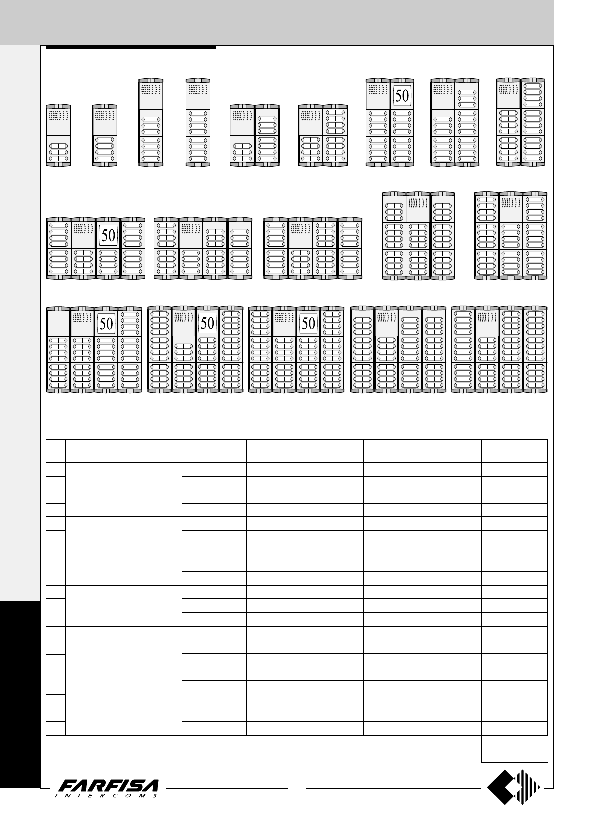
1 ROW INTERCOM push-button panels 2 ROW INTERCOM push-button panels
AG100A AG100T AG20
N. buttons
AG30ED
1
1
2
3
4
5
6
7
8
9
10
11
12
13
14
15
16
17
18
19
20
21
22
23
24
25
26
27
28
29
30
31
32
33
34
35
36
1
1
1
1
1
1
1
1
1
1
1
1
1
1
1
1
1
1
1
1
1
1
1
1
1
1
1
1
1
1
1
1
1
1
1
1
1
1
1
1
1
1
1
1
1
1
1
1
1
1
1
1
1
1
1
1
1
1
1
1
1
1
1
1
1
1
1
1
1
1
1
-
-
-
-
1
1
1
1
1
1
1
1
2
2
2
2
2
2
2
2
3
3
3
3
3
3
3
3
4
4
4
4
4
4
4
4
AG21
1
3
2
2
3
1
4
-
5
7
6
6
7
5
8
4
9
3
10
2
11
1
12
-
13
7
14
6
15
5
16
4
17
3
18
2
19
1
20
-
21
7
22
6
23
5
24
4
25
3
26
2
27
1
28
-
29
7
30
6
31
5
32
4
33
3
34
2
35
1
36
-
N. buttons
AG100A AG100T AG20
AG30ED
2
1
4
6
8
10
12
14
16
18
20
22
24
26
28
30
32
34
36
38
40
42
44
46
48
50
52
54
56
58
60
62
64
66
68
70
72
1
1
1
1
1
1
1
1
1
1
1
1
1
1
1
1
1
1
1
1
1
1
1
1
1
1
1
1
1
1
1
1
1
1
1
1
1
1
1
1
1
1
1
1
1
1
1
1
1
1
1
1
1
1
1
1
2
1
2
1
2
1
2
1
2
1
2
1
2
1
2
1
3
1
3
1
3
1
3
1
3
1
3
1
3
1
3
1
4
1
4
1
4
1
4
1
4
1
4
1
4
1
4
-
-
-
-
AG222
1
3
2
2
3
1
4
-
5
7
6
6
7
5
8
4
9
3
10
2
11
1
12
-
13
7
14
6
15
5
16
4
17
3
18
2
19
1
20
-
21
7
22
6
23
5
24
4
25
3
26
2
27
1
28
-
29
7
30
6
31
5
32
4
33
3
34
2
35
1
36
-
A
G
O
R
À
21
(MT11 - Gb2012)
Page 24
EXTERNAL DOOR STA TIONS
1+1
Push-button panels in extruded aluminium and
steel push-buttons made up of modular ele-
INTERCOMS *
ments. Suitable for the most diverse installation requirements. The careful selection of
modules allows for multiple application opportunities; from one-way installations to blocks of
flats; from intercom to video intercom installations.
The optimized size of modules allows for easy
installation on the gage jamb.
4+1
VIDEOINTERCOMS
Hood covers
PROFILO SERIES
Module frames complete with back box
PL 71 PL 72 PL 73
PL 81 PL 83PL 82 PL 84 PL 86 PL 89
Rain shelters with module frames
P
R
O
F
I
PL 91 PL 93PL 92 PL 94 PL 96 PL 99
L
O
22
(MT11 - Gb2012)
Page 25
EXTERNAL DOOR STA TIONS
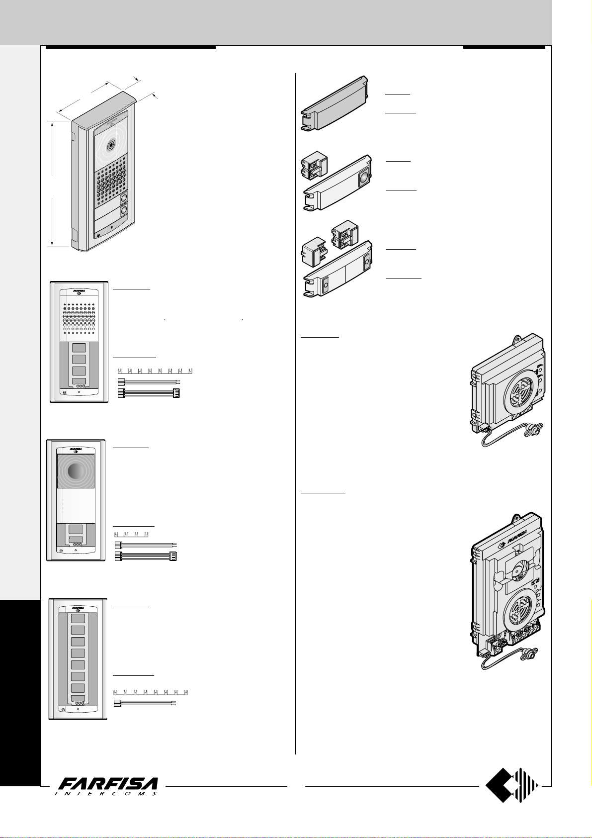
PROFILO push-button panel
Modules with integrated door speaker
PL10PED
without call buttons
PL 50
number module
PL11PED
with 1 call button
PL 20
blank module
PL12PED
with 2 call buttons
Push-button modules
Video modules with integrated door speaker
PL40PED
without call buttons and
with B\W camera
PL40PCED
colour version
For specifications see page 24.
PL41PED
with 1 call button and B\W
camera
PL41PCED
colour version
PL42PED
with 2 call buttons and
B\W camera
PL42PCED
colour version
1+1
INTERCOMS *
4+1
VIDEOINTERCOMS
PL 21
with 1 call button
Access control modules
FC 52PL
Keypad module
for access control
(see characteristics on page 25).
Technical characteristics and terminal boards of the audio-video modules
PL10PED PL11PED PL12PED PL40PED PL41PED PL42PED
1111 1 1
EEEE E E
SSSS S S
AAAA A A
---- - CC C C
P1 P1 P1 P1
L+ L+ L+ L+ L+ L+
PL 22
with 2 call buttons
FP 52PL
Proximity reader for
access control (see
characteristics on
page 25).
PL40PCED PL41PCED PL42PCED
P2 P2
XXX
YYY
HHH
FFF
PL 23
with 3 call buttons
Technical characteristics and terminal boards of the button modules
PL21 PL22 PL23 PL24 PL226 PL228 PL50
AAAAAAA
(25mA) (50mA) (0.1A)
------C C C C C/C2 C/C2
P1 P1 P1 P1 P1 P1
PL 24
with 4 call buttons
P2 P2 P2 P2 P2
P3 P3 P3 P3
P4 P4
Reception-transmission; electric lock release; call
Reception-transmission; electric lock release
Electric lock
DC power supply input for door speaker and name-plate Led (13Vac-70mA)
Ground
Call push-buttons common
Call push-button
Call push-button
Negative video signal output
Positive video signal output
Positive voltage input for camera (18÷24Vdc)
Video ground
DC power supply input for service Led (12Vdc)
P5÷P7 P5÷P7
P8
PL226
with 6 call buttons (2 row)
AC power supply input for nameplate
Led (13Vac)
Ground
Call push-buttons common
Call push-button
Call push-button
Call push-button
Call push-button
Call push-buttons (C2 common)
Call push-button (C2 common)
PL228
with 8 call buttons (2 row)
P
R
O
F
I
L
O
23
(MT11 - Gb2012)
Page 26
EXTERNAL DOOR ST ATIONS
1+1
Video modules with integrated door speaker
INTERCOMS *
Testing and adjustments
Adjustments are carried out in the factory; should
any be necessary they can be readjusted from
the outside with a screwdriver with the trimmers
identified by the symbols "
Volumes adjustment
To adjust the volume of microphone and loudspeaker, turn the trimmers
" and .
and .
4+1
PL40PED. Modules complete with:
- CCD color camera with autoiris and fixed
3.6mm lens.
VIDEOINTERCOMS
- amplified speaker unit with volume
adjustment of 2 channels (reception and
transmission)
- aluminium front plate with transparent
screen
- horizontal and vertical adjustments
- red operation LED
PL40PCED.
Colour version of the PL40PED model.
PL41PED.
Same as PL40PED, with 1 call button and
name plate panel with transparent screen
and green LED backlighting.
PL41PCED.
Colour version of the PL41PED model.
PL42PED.
Same as PL40PED, with 2 call buttons
and name plate panel with transparent
screen and green LED backlighting.
PL42PCED.
Colour version of the PL42PED model.
241DMA. Module with diodes for 4 users.
It allows for the use of the button modules PL21,
PL22, PL23, PL24, PL226 and PL228 in the 1+1
intercom systems and 4+1 video intercom systems. It is fixed on the back of the button modules
using the 2 supplied screws. Connect the conductors of the diode module to the corresponding
terminal on button module; if modules with a reduced number of Push-buttons are used (PL21,
PL22, PL23, PL226) do not connect and insulate
the excess of wires.
Cut a portion of the metal terminals to connect the
conductors to the terminal board of push buttons
modules.
Antilocale adjustment
In case of "feedback" (Larsen effect) in the
external unit it is necessary to operate as follow:
- make the call from the door station and lift the
handset of an intercom or videointercom
(press
- adjust the trimmer
(Larsen effect).
Receiver
adjustable volume
Receiver
adjustable volume
for Echos series);
until the whistling stops
Transmitter
PL40P...
S
FHX
L+
Y
Transmitter
volumeadjustable
Anti-feedback
(Larsen effect)
adjustment
volumeadjustable
PL21
PL22
Technical data PL40PED-PL41PED- PL40PCED-PL41PCED-
Camera power supply 18÷24Vdc-0.3A 18÷24Vdc-0.4A
Audio power supply 13Vac-0.07A 13Vac-0.07A
Video signal output balanced balanced
Video signal standard CCIR PAL
Minimum illumination 2 Lux 2.5 Lux
White balanced - auto
P
Led's 6 infrared 6 white
Sensor CCD 1/4" B/W CCD 1/3" colour
R
Number of pixels 291,000 291,000
Horizontal frequency 15,625Hz 15,625Hz
O
Vertical frequency 50Hz 50Hz
Lens 3.6mm 3.6mm
Focus 0.1m ÷ ∞ 0.6m ÷ ∞
F
Autoiris electronic electronic
Horizontal adjustment ± 15° ± 15°
I
Vertical adjustment ± 15° ± 15°
Operating temperature -10°÷+40°C -10°÷+40°C
L
Maximum permissible humidity 80%RH 80%RH
PL42PED PL42PCED
PL23
PL24
PL226
PL228
O
PL10P...
S
L+
Anti-feedback
(Larsen effect)
adjustment
Adjustments
You can manually change the camera framing
by unloosening and adjusting the horizontal
and vertical screws in the desired direction.
±15°
24
(MT11 - Gb2012)
Page 27
EXTERNAL DOOR STA TIONS
PROXIMITY READER FOR ACCESS
CONTROL
FP52PL.
This article allows for the activation of 2 relays
by means of keytags or electronic ISO cards
based on transponder technology.
Programmable activation time from 1 to 63
seconds for every relay. 4 user cards and 1
master card supplied with the product. Acoustic
and visual control signals and 3-digit display to
view numbers and codes during set-up and
operation.
Technical data
Power supply 12Vac/dc ±10%
Stand-by current 0.1A
Maximum current consumption 0.25A
Contact ratings 24Vac - 2A
Max. number of cards 490
Max. number of Master cards 10
Number of relays 2
Relay time 1 to 63 sec.
Minimum recognition distance 3 cm
Maximum recognition time 1 sec.
Operating temperature 0° ÷ +40°C
Maximum permitted humidity 85% RH
Terminals
+/A positive or alternate current input
-/A ground or alternate current input
PB door open button
NC2 normally closed contact of relay 2
NA2 normally open contact of relay 2
C2 common terminal of relay 2
NC1 normally closed contact of relay 1
NA1 normally open contact of relay 1
C1 common terminal of relay 1
ACCESS CONTROL KEYPAD
FC 52PL.
Access control keypad with 12 digits and 2
relays for lock release. 4 programmable access codes for each relay. Programmable door
opening time from 1 up 99 sec. for each relay
(or bistable operation of relay 1). Acoustic and
visual confirmation for entered keys, accepted
programming and for wrong codes.
Technical data
Power supply: 12Vac/dc ±10%
Stand-by current: 0.06A
Maximum current consumption: 0.15A
Contact ratings: 12Vac-2A
Numbers of codes for relays 1: 12 or direct
activation
Numbers of codes for relays 2: 12 or direct
activation
Activation time for each relay: from 1 to 99 sec.
(or bistable relay 1)
Operating temperature: 0° ÷ +40°C
Maximum permissible humidity: 85% RH
Terminals
NC2 normally closed contact of relay 2
NA2 normally open contact of relay 2
C2 common contact of relay 2
NC1 normally closed contact of relay 1
NA1 normally open contact of relay 1
C1 common contact of relay 1
ground or alternate voltage input
positive or alternate voltage input
P2 activation of the relay 2; if momentarily
connected to ground it allows the activation for the programmed time
P1 activation of the relay 1; if momentarily
connected to ground it allows the activation for the programmed time
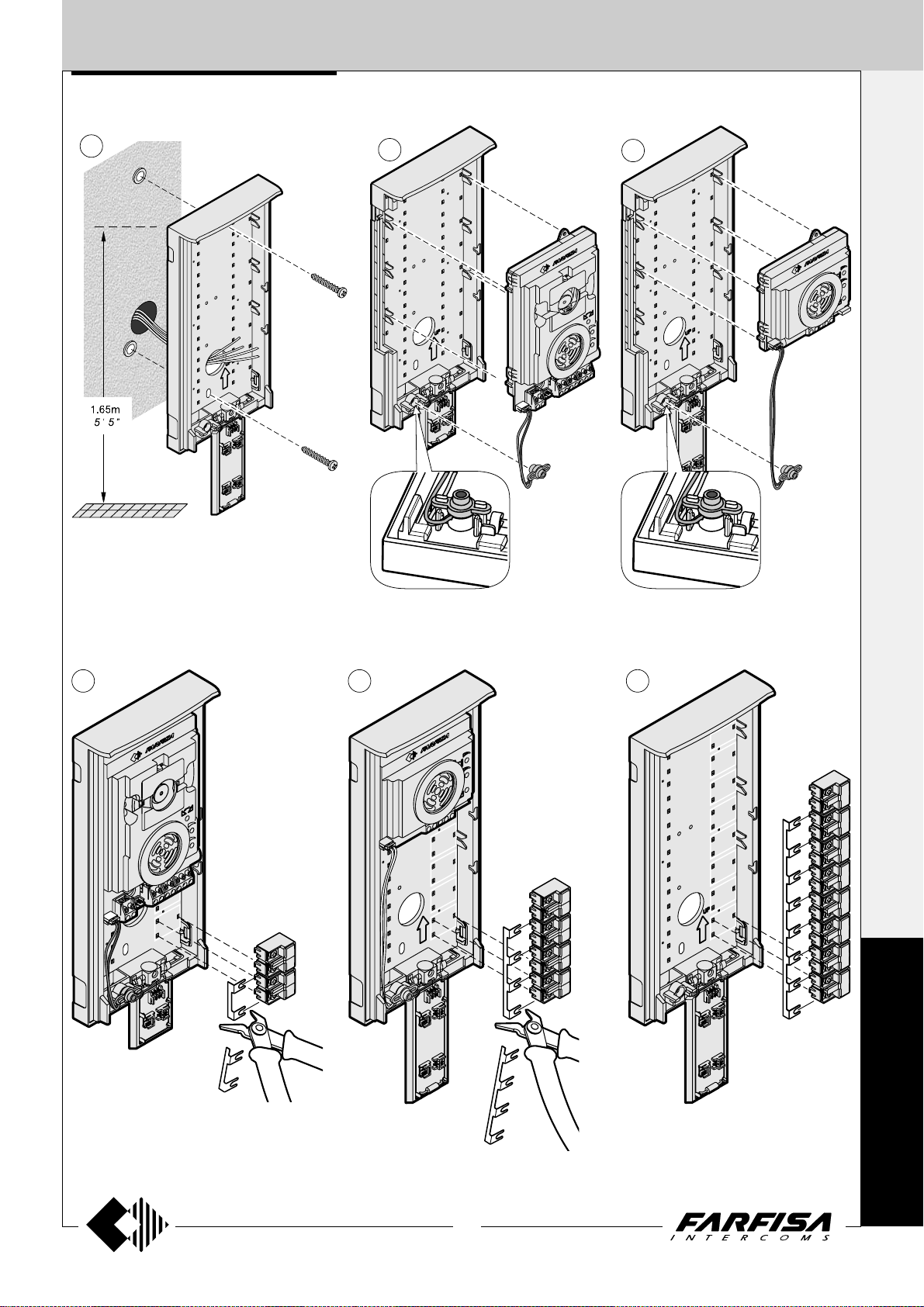
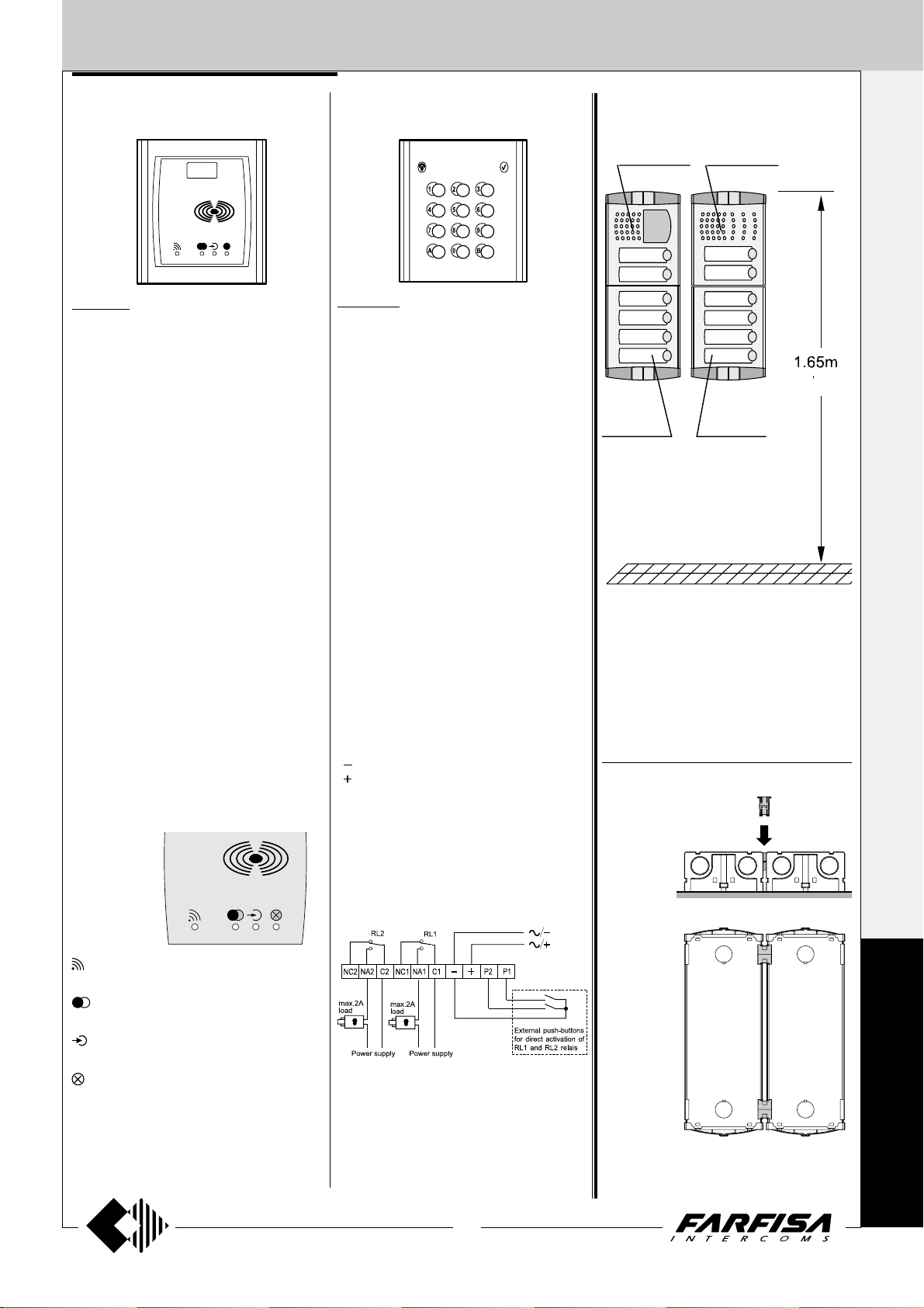
INSTALLATION
PL42PED
PL24
Place the push-button panel back box at a
height of about 1.65m (5' 5") from the floor
keeping the front edges flush-mounted and vertical to the finished plaster.
Position the camera in such a way that
sunlight or other direct or reflected light
sources with high intensity do not hit the
camera lens.
PL12PED
PL24
"
5
5
Assembling modules side by side
1+1
INTERCOMS *
4+1
VIDEOINTERCOMS
Card recognition LED. It turns ON during card recognition.
Relay activation LED. It indicates relay
deactivation (red) or activation (green).
Program LED. It turns ON during system
programming.
Card cancellation and system setup
LED. It turns ON during Master or user
card cancellation and system setup.
25
(MT11 - Gb2012)
Insertion of spacers between back boxes.
Spacers and cable bushing (not supplied with
the products) must be inserted before brick
work.
P
R
O
F
I
L
O
Page 28
EXTERNAL DOOR ST ATIONS
1+1
INTERCOMS *
4+1
VIDEOINTERCOMS
Openings for cables.
Fix lower part of the
frame to the back box
and make the electrical connections.
Rain shelter
Fix lower part of the
frame to the rain shelter
and make the electrical
connections.
P
R
O
F
I
L
Flush mounting and cables placing.
Mounting of
module.
Fixing of module frames to the upper side by the
2 small screws included in the back boxes.
Fixing of frame to back box.
Align the frame before tightening the screws.
Fixing of module frames to the upper side by
the 2 small screws included in the rain shelter.
Fixing of frame to rain shelter.
Align the frame before tightening the screws.
O
26
(MT11 - Gb2012)
Page 29
EXTERNAL DOOR STA TIONS
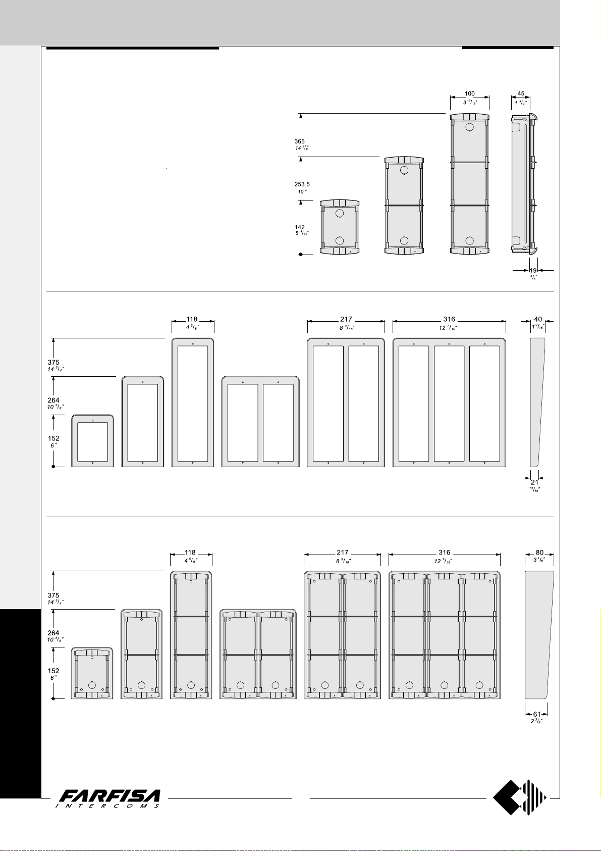
1 row push button
1 ROW PUSH BUTTON PANELS
1 call button
2 call
buttons
22 call buttons
4 call
buttons
6 call
buttons
25 call buttons 28 call buttons 30 call buttons
buttons
8 call
10 call
buttons
Examples of compositions in intercom systems
11 call buttons 14 call buttons
17 call buttons
20 call buttons
31 call buttons
1+1
INTERCOMS *
4+1
VIDEOINTERCOMS
34 call buttons
N°
Dimensions
calls
1
2
4
6
8
10
11
14
100x142x19
15
/16" x 5 9/16" x 3/4")
(3
100x253,5x19
15
/16" x 10" x 3/4")
(3
100x365x19
15
(3
/16" x 14 3/8" x 3/4")
200x253,5x19
7
/8" x 10" x 3/4")
(7
17
20
200x365x19
7
(7
/8" x 14 3/8" x 3/4")
22
25
28
400x253,5x19
3
/4" x 10" x 3/4")
(15
30
31
34
300x365x19
13
/16" x 14 3/8" x 3/4")
(11
38
40
42
400x365x19
3
/4" x 14 3/8" x 3/4")
(15
46
(**) If requested the hood covers can be added (see
on page 22)
Door speaker
module (ampl.)
1 PL11PED
1 PL12PED
1 PL10PED
1 PL12PED
1 PL10PED
1 PL12PED
1 PL11PED
1 PL12PED
1 PL11PED
1 PL12PED
1 PL12PED
1 PL11PED
1 PL10PED
1 PL12PED
1 PL11PED
1 PL12PED
1 PL12PED
1 PL10PED
1 PL12PED
1 PL12PED
40 call buttons
42 call buttons
46 call buttons38 call buttons
Composition board of Profilo push-button panels.
Button, blank or informa-
tion modules
-
1 PL24
1 PL24
2 PL24
2 PL24
2 PL24
3 PL24
4 PL24
4 PL24
5 PL24
6 PL24
7 PL24
7 PL24
7 PL24
8 PL24
9 PL24
10 PL24
10 PL24
11 PL24
-
-
-
-
-
-
1 PL22
-
(*)
1 PL20
1 PL22
-
(*)
1 PL20
-
-
1 PL22
-
(*)
2 PL20
1 PL20 (*)
1 PL20 (*)
-
(*) or PL50
4 diode
module
-
1 241DMA
1 241DMA
2 241DMA
2 241DMA
3 241DMA
3 241DMA
4 241DMA
5 241DMA
5 241DMA
6 241DMA
7 241DMA
7 241DMA
8 241DMA
8 241DMA
9 241DMA
10 241DMA
10 241DMA
11 241DMA
Back box and
module frame
(**)
1 PL71
1 PL71 (**)
1 PL72 (**)
1 PL72 (**)
1 PL73 (**)
1 PL73 (**)
2 PL72 (**)
2 PL72 (**)
2 PL73 (**)
2 PL73 (**)
2 PL73 (**)
4 PL72
4 PL72
4 PL72
(**)
3 PL73
3 PL73 (**)
4 PL73
4 PL73
4 PL73
4 PL73
Rain
shelters
1 PL91
1 PL91
1 PL92
1 PL92
1 PL93
1 PL93
1 PL94
1 PL94
1 PL96
1 PL96
1 PL96
-
-
1 PL99
1 PL99
-
-
-
-
It replaces
PL71, PL72 or PL73
P
R
O
F
I
L
O
27
(MT11 - Gb2012)
Page 30
EXTERNAL DOOR STA TIONS
2 ROW PUSH BUTTON PANELS
1+1
INTERCOMS *
2 row push button
Examples of compositions in intercom systems
6 call
4+1
buttons
8 call
buttons
14 call
buttons
VIDEOINTERCOMS
48 call buttons 52 call buttons 56 call buttons
72 call buttons
N°
Dimensions
calls
6
8
14
16
20
24
100x253,5x19
15
/16" x 10" x 3/4")
(3
100x365x19
15
/16" x 14 3/8" x 3/4")
(3
200x253,5x19
7
/8" x 10" x 3/4")
(7
32
200x365x19
36
7
(7
/8" x 14 3/8" x 3/4")
40
P
48
52
56
400x253,5x19
3
(15
/4" x 10" x 3/4")
60
R
62
300x365x19
13
/16" x 14 3/8" x 3/4")
(11
64
O
F
I
72
78
80
82
400x365x19
3
(15
/4" x 14 3/8" x 3/4")
88
L
(**) If requested the hood covers can be added (see on
page 22)
O
16 call
buttons
Door speaker
module (ampl.)
1 PL10PED
1 PL10PED
1 PL10PED
1 PL10PED
1 PL10PED
1 PL10PED
1 PL10PED
1 PL10PED
1 PL10PED
1 PL10PED
1 PL10PED
1 PL10PED
1 PL10PED
1 PL10PED
1 PL10PED
1 PL10PED
1 PL10PED
1 PL10PED
1 PL10PED
1 PL10PED
20 call buttons 24 call buttons 40 call buttons
60 call buttons
80 call buttons
82 call buttons
36 call buttons32 call buttons
64 call buttons
88 call buttons78 call buttons
Composition board of Profilo push-button panels.
Button, blank or information
modules
1 PL226
1 PL228
1 PL228
2 PL228
1 PL228
3 PL228
4 PL228
3 PL228
5 PL228
6 PL228
5 PL228
7 PL228
6 PL228
7 PL228
8 PL228
9 PL228
9 PL228
10 PL228
8 PL228
11 PL228
-
-
1 PL226
-
2 PL226
-
1 PL20
2 PL226
-
1 PL20
2 PL226
2 PL226
1 PL226
-
2 PL20
1 PL226
1 PL20
3 PL226
-
(*)
(*)
(*)
1 PL20 (*)
(*)
(*) or PL50
4 diode
module
2 241DMA
2 241DMA
4 241DMA
4 241DMA
6 241DMA
6 241DMA
8 241DMA
10 241DMA
10 241DMA
12 241DMA
14 241DMA
14 241DMA
16 241DMA
16 241DMA
16 241DMA
18 241DMA
20 241DMA
20 241DMA
22 241DMA
22 241DMA
Back box and
module frame
(**)
1 PL72
1 PL72 (**)
1 PL73 (**)
1 PL73 (**)
2 PL72 (**)
2 PL72 (**)
2 PL73 (**)
2 PL73 (**)
2 PL73 (**)
4 PL72
4 PL72
4 PL72
(**)
3 PL73
3 PL73 (**)
3 PL73 (**)
4 PL73
4 PL73
4 PL73
4 PL73
4 PL73
Rain
shelters
1 PL92
1 PL92
1 PL93
1 PL93
1 PL94
1 PL94
1 PL96
1 PL96
1 PL96
-
-
1 PL99
1 PL99
1 PL99
-
-
-
-
-
It replaces
PL72 or PL73
28
(MT11 - Gb2012)
Page 31

EXTERNAL DOOR STA TIONS
1 row push button
1 ROW PUSH BUTTON PANELS
1 call button
2 call
buttons
22 call buttons
4 call
buttons
6 call
buttons
25 call buttons 28 call buttons 30 call buttons
buttons
8 call
10 call
buttons
Examples of compositions in videointercom systems
11 call buttons 14 call buttons
17 call buttons
20 call buttons
31 call buttons
1+1
INTERCOMS *
4+1
VIDEOINTERCOMS
34 call buttons
N°
Dimensions
calls
1
2
4
6
8
10
11
14
100x142x19
15
/16" x 5 9/16" x 3/4")
(3
100x253,5x19
15
/16" x 10" x 3/4")
(3
100x365x19
15
/16" x 14 3/8" x 3/4")
(3
200x253,5x19
7
/8" x 10" x 3/4")
(7
17
20
200x365x19
7
/8" x 14 3/8" x 3/4")
(7
22
25
28
400x253,5x19
3
(15
/4" x 10" x 3/4")
30
31
34
300x365x19
13
/16" x 14 3/8" x 3/4")
(11
38
40
42
400x365x19
3
/4" x 14 3/8" x 3/4")
(15
46
(**) If requested the hood covers can
be added (see on page 22)
Camera and door
speaker module
1 PL41PED
1 PL42PED
1 PL40PED
1 PL42PED
1 PL40PED
1 PL42PED
1 PL41PED
1 PL42PED
1 PL41PED
1 PL42PED
1 PL42PED
1 PL41PED
1 PL40PED
1 PL42PED
1 PL41PED
1 PL42PED
1 PL42PED
1 PL40PED
1 PL42PED
1 PL42PED
or PL40PCED,
PL41PCED,
PL42PCED
40 call buttons
42 call buttons
46 call buttons38 call buttons
Composition board of Profilo push-button panels.
Button, blank or informa-
tion modules
-
1 PL24
1 PL24
2 PL24
2 PL24
2 PL24
3 PL24
4 PL24
4 PL24
5 PL24
6 PL24
7 PL24
7 PL24
7 PL24
8 PL24
9 PL24
10 PL24
10 PL24
11 PL24
-
-
-
-
-
-
1 PL22
-
(*)
1 PL20
1 PL22
-
(*)
1 PL20
-
-
1 PL22
-
(*)
2 PL20
1 PL20 (*)
1 PL20 (*)
-
(*) or PL50
4 diode
module
-
1 241DMA
1 241DMA
2 241DMA
2 241DMA
3 241DMA
3 241DMA
4 241DMA
5 241DMA
5 241DMA
6 241DMA
7 241DMA
7 241DMA
8 241DMA
8 241DMA
9 241DMA
10 241DMA
10 241DMA
11 241DMA
Back box and
module frame
(**)
1 PL71
1 PL71 (**)
1 PL72 (**)
1 PL72 (**)
1 PL73 (**)
1 PL73 (**)
2 PL72 (**)
2 PL72 (**)
2 PL73 (**)
2 PL73 (**)
2 PL73 (**)
4 PL72
4 PL72
4 PL72
(**)
3 PL73
3 PL73 (**)
4 PL73
4 PL73
4 PL73
4 PL73
Rain
shelters
1 PL91
1 PL91
1 PL92
1 PL92
1 PL93
1 PL93
1 PL94
1 PL94
1 PL96
1 PL96
1 PL96
-
-
1 PL99
1 PL99
-
-
-
-
It replaces
PL71, PL72 or PL73
P
R
O
F
I
L
O
29
(MT11 - Gb2012)
Page 32

EXTERNAL DOOR STA TIONS
2 ROW PUSH BUTTON PANELS
1+1
INTERCOMS *
2 row push button
Examples of compositions in videointercom systems
6 call
4+1
buttons
8 call
buttons
14 call
buttons
16 call
buttons
VIDEOINTERCOMS
48 call buttons 52 call buttons 56 call buttons
72 call buttons
Camera and door
speaker module
1 PL40PED
1 PL40PED
1 PL40PED
1 PL40PED
1 PL40PED
1 PL40PED
1 PL40PED
1 PL40PED
1 PL40PED
1 PL40PED
1 PL40PED
1 PL40PED
1 PL40PED
1 PL40PED
1 PL40PED
1 PL40PED
1 PL40PED
1 PL40PED
1 PL40PED
1 PL40PED
P
R
O
F
I
N°
calls
6
8
14
16
20
24
32
36
40
48
52
56
60
62
64
72
78
80
82
88
Dimensions
100x253,5x19
15
/16" x 10" x 3/4")
(3
100x365x19
15
/16" x 14 3/8" x 3/4")
(3
200x253,5x19
7
/8" x 10" x 3/4")
(7
200x365x19
7
/8" x 14 3/8" x 3/4")
(7
400x253,5x19
3
(15
/4" x 10" x 3/4")
300x365x19
13
/16" x 14 3/8" x 3/4")
(11
400x365x19
3
/4" x 14 3/8" x 3/4")
(15
L
(**) If requested the hood covers can be added (see on page 22)
O
20 call buttons 24 call buttons 40 call buttons
80 call buttons
82 call buttons
36 call buttons32 call buttons
60 call buttons
64 call buttons
88 call buttons78 call buttons
Composition board of Profilo push-button panels.
Button, blank or information
modules
1 PL226
1 PL228
1 PL228
2 PL228
1 PL228
3 PL228
4 PL228
3 PL228
5 PL228
6 PL228
5 PL228
7 PL228
6 PL228
7 PL228
8 PL228
9 PL228
9 PL228
10 PL228
8 PL228
11 PL228
-
-
1 PL226
-
2 PL226
-
1 PL20
2 PL226
-
1 PL20
2 PL226
2 PL226
1 PL226
-
2 PL20
1 PL226
1 PL20
3 PL226
-
(*)
(*)
(*)
1 PL20(*)
(*)
(*) or PL50
4 diode
module
2 241DMA
2 241DMA
4 241DMA
4 241DMA
6 241DMA
6 241DMA
8 241DMA
10 241DMA
10 241DMA
12 241DMA
14 241DMA
14 241DMA
16 241DMA
16 241DMA
16 241DMA
18 241DMA
20 241DMA
20 241DMA
22 241DMA
22 241DMA
Back box and
module frame
(**)
1 PL72
1 PL72 (**)
1 PL73 (**)
1 PL73 (**)
2 PL72 (**)
2 PL72 (**)
2 PL73 (**)
2 PL73 (**)
2 PL73 (**)
4 PL72
4 PL72
4 PL72
(**)
3 PL73
3 PL73 (**)
3 PL73 (**)
4 PL73
4 PL73
4 PL73
4 PL73
4 PL73
Rain
shelters
1 PL92
1 PL92
1 PL93
1 PL93
1 PL94
1 PL94
1 PL96
1 PL96
1 PL96
-
-
1 PL99
1 PL99
1 PL99
-
-
-
-
-
It replaces
PL72 or PL73
30
(MT11 - Gb2012)
Page 33

EXTERNAL DOOR STA TIONS
Stainless steel (AISI 316L) anti-vandalism pushbutton panels especially studied to withstand
burglary, penetration of solids and water jets (IP
45 protection degree against the penetration of
external solids and water; IK09 against shocks).
The Matrix push-button panels include back boxes,
module frames, die-cast aluminium decorative
frames, button modules, and modules with built-in
speaker unit (with or without camera).
The careful selection of modules allows for multiple
application opportunities; from one-way
installations to blocks of flats; from intercom to
video intercom installations.
The push-button elements have been developed
to allow both for horizontal and vertical
configuration.
Module frames complete with back box
MA 71 MA 72 MA 73
MATRIX SERIES
1+1
INTERCOMS *
4+1
VIDEOINTERCOMS
Notice! To maintain the brilliance of
door station plates, periodic cleaning
with specific products for stainless steel
is required.
Front frames
MA 61
MAS 61
Rain shelters with module frames
MA 62
MAS 62
MA 63
MAS 63
MA 91 MA 93MA 92
31
(MT11 - Gb2012)
M
A
T
R
I
X
Page 34

EXTERNAL DOOR STA TIONS
1+1
AMPLIFIED DOOR STATIONS
INTERCOMS *
4+1
VIDEOINTERCOMS
MAS10PED. Audio module without
push-buttons. Complete with amplified door
speaker in two channels and control of volume
of "receiver", stainless steel front plate and red
operation LED.
MAS11PED. They are different from the
previous model for the presence of a calling
push-button and nameplate, realized with vandal proof polycarbonate and backlighted with
green LED’s.
MAS12PED. Module with 2 call buttons.
Terminals
A Supply 13VAC-70mA
- Ground
1 Reception-transmission; electric lock release;
call
S Electric lock
E Reception-transmission; electric lock release
P1-P2 Call push-buttons
C Call push-buttons common
L+ DC power supply input for service Led
CAMERAS
MAS43ED.
B/W camera module for 4+1 video systems
without coaxial cable, including:
- solid-state CCD camera, with auto iris, 3.6mm
fixed optics and 6 infrared LED’s;
- stainless steel front plate complete with transparent anti-temper screen, steel call button
with corresponding name plate holder;
- horizontal/vertical adjustment;
- red operation LED;
- amplified door speaker.
MAS43CED.
Colour version of the MAS43ED model.
Terminals
A Supply 13VAC-70mA
- Ground
1 Reception-transmission; electric lock re-
lease; call
S Electric lock
E Reception-transmission; electric lock release
P Call push-button
C Call push-button common
L+ DC power supply input for service Led
Y Positive video signal output
F Ground
X Negative video signal output
H Positive power supply input 21Vdc
Testing and adjustments
Adjustments are carried out in the factory;
should any be necessary they can be re-adjusted from the outside with a screwdriver with
the trimmers identified by the symbols "
and
Volume adjustment
To increase the volume from the amplifier in
the transmission mode, turn the trimmer “
in a clockwise direction.
Antilocale adjustment
In case of "feedback" (Larsen effect) in the
external unit it is necessary to operate as
follow:
- make the call from the door station and lift the
- adjust the trimmer until the whistling
.
handset of an intercom or videointercom
(press
stops (Larsen effect).
MAS10PED MAS11PED MAS12PED
for Echos series);
Feedback
adjustment
L+
CP2P1
E
Receiver adjustable
volume
Receiver adjustable
volume
A
S
1
Feedback
adjustment
"
"
L+
CP2P1
E
Technical data MAS43ED MAS43CED
Power supply 18÷24Vdc 18÷24Vdc
Operating current 0.3A 0.4A
Video signal output balanced balanced
M
Video signal standard CCIR PAL
Minimum illumination 2 Lux 2.5 Lux
White balanced - auto
A
Sensor CCD 1/4" B/W CCD 1/3" colour
Number of pixels 291,000 291,000
T
Horizontal frequency 15,625Hz 15,625Hz
Vertical frequency 50Hz 50Hz
R
Lens 3.6mm 3.6mm
Focus 0,1m ÷ ∞ 0,6m ÷ ∞
Autoiris electronic electronic
I
Horizontal adjustment ± 15° ± 15°
Vertical adjustment ± 15° ± 15°
X
Operating temperature -10°÷+40°C -10°÷+40°C
Maximum permissible humidity 80%RH 80%RH
S
A
1
CPXYHFAS1EL+
CPXYHFAS1EL+
MAS43ED MAS43CED
Adjustments
You can manually change the camera framing
by unloosening and adjusting the horizontal
and vertical screws in the desired direction.
(±15°)
MAS43ED
MAS43CED
32
(MT11 - Gb2012)
Page 35

EXTERNAL DOOR ST ATIONS
P2 P1
RL1
RL2
For direct activation
of RL1 and RL2
Max 2A
load
Max 2A
load
Power
supply
Power
supply
Push-button modules
MAS20. Blank module in stainless steel.
MAS22. Module with 2 call buttons and name plate panel with
breakproof transparent screen and green LED backlight.
MAS24. With 4 call buttons.
241DMA. Module with diodes for 4 users.
It allows for the use of the button modules MAS22 and MAS24 in the 1+1
intercom systems and 4+1 video intercom systems. It is fixed on the
back of the button modules using the 2 supplied screws. Connect the
conductors of the diode module to the corresponding terminal on
MAS24 module; if MAS22 module is used do not connect P3 and P4
conductors and properly insulate them.
ACCESS CONTROL KEYPAD
FC52MAS. Electronic keypad with 12 keys
and 2 relays for lock release and access control
of door stations. 12 programmable access codes
for each relay. Programmable door opening time
from 1 up 99 sec. for each relay (or bistable
operation of relay). Acoustic and visual confirmation for entered keys, accepted programming
and for wrong codes.
Technical data
Power supply: 12Vac/dc ±10%
Stand-by current: 0.02A
Max. current consumption: 0.1A
Contact ratings: 12Vac - 2A
Numbers of codes for relay 1: 12 + direct activation
Numbers of codes for relay 2: 12 + direct activation
Activation time for each relay: from 1 to 99 seconds (or bistable)
Operating temperature: 0° ÷ +40°C
Maximum permissible humidity: 85% RH
Degree of protection IP 45
Terminals
normally closed contact of relay 2
2 normally open contact of relay 2
common contact of relay 2
normally closed contact of relay 1
1 normally open contact of relay 1
common contact of relay 1
ground or alternating voltage input
positive or alternating voltage input
P2 activation of the relay 2; if momentarily connected to ground it allows the
activation for the programmed time
P1 activation of the relay 1; if momentarily connected to ground it allows the
activation for the programmed time
1+1
INTERCOMS *
4+1
VIDEOINTERCOMS
Technical characteristics of MA TRIX modules terminal boards
MAS10PED MAS11PEDMAS12PED MAS22 MAS24 MAS43ED
111 1
EEE E
SSS S
AAAAAA
-----C C CCC
P1 P1 P1 P1 P
P2 P2 P2
P3
P4
L+ L+ L+ L+
MAS43CED
X
Y
H
F
(MT11 - Gb2012)
Reception-transmission; electric lock release; call
Reception-transmission; electric lock release
Electric lock
Alternated power supply input for door speaker and name-plate Led (13Vac-70mA)
Ground
Call push-buttons common
Call push-button
Call push-button
Call push-button
Call push-button
Negative video signal output
Positive video signal output
Positive voltage input for camera (18÷24Vdc)
Video ground
DC power supply input for service Led (12Vdc)
33
M
A
T
R
I
X
Page 36

EXTERNAL DOOR STA TIONS
1+1
INSTALLATION
INTERCOMS *
4+1
VIDEOINTERCOMS
Assembling modules side by side
Flush mounting and cables placing.
Place the push-button panel back box at a
height of about 1.65m (5' 5") from the floor
keeping the front edges flush-mounted and
vertical to the finished plaster.
Position the camera in such a way that
sunlight or other direct or reflected light
sources with high intensity do not hit
the camera lens.
Insertion of spacers between back
boxes. Spacers and cable bushing
(not supplied with the products) must
be inserted before brick work.
Mounting modules.
M
A
Openings for cables.
T
R
I
X
For easier connection to the electrical system, it is
recommended to insert the metal plate supplied
with the product in the back box opening, as
shown in the figure. The plate is used to hook the
frame with pre-assembled modules.
Leave the plate in the box to reuse it for
maintenance operations.
34
(MT11 - Gb2012)
Page 37

EXTERNAL DOOR STA TIONS
a
a
a
a
a
a
a
a
a
a
a
a
a
a
a
a
a
a
a
a
a
a
a
a
a
a
a
a
a
a
a
a
a
a
a
a
a
a
aaaaaaaaaaaaaa
Connection of wires to module terminal boxes.
1+1
INTERCOMS *
4+1
VIDEOINTERCOMS
Fixing of frame to module frame.
Apply the protection gaskets supplied with the product
on the internal part of the frame openings.
Rain shelters
aaaaaaaaaaaa
aaaaaaaaaaaa
aaaaaaaaaaaa
aaaaaaaaaaaa
aaaaaaaaaaaa
aaaaaaaaaaaa
aaaaaaaaaaaa
aaaaaaaaaaaa
aaaaaaaaaaaa
aaaaaaaaaaaa
aaaaaaaaaaaa
aaaaaaaaaaaa
aaaaaaaaaaaa
aaaaaaaaaaaa
Fixing of frame to back
box.
Align the frame before
tightening the screws.
aaaaaaaaaaaa
aaaaaaaaaaaa
aaaaaaaaaaaa
aaaaaaaaaaaa
aaaaaaaaaaaa
M
A
Fixing of frame to rain shelter.
Align the frame before tightening
* Long screws can be used to anchor
the frame during wire connection tp
modules.
35
(MT11 - Gb2012)
the screws.
T
R
I
X
Page 38

EXTERNAL DOOR ST ATIONS
1+1
INTERCOMS *
1 call button
2 call buttons
4+1
VIDEOINTERCOMS
4 call buttons 10 call buttons6 call buttons 6 call buttons
14 call buttons
3 call buttons
Examples of compositions in intercom systems
7 call buttons
9 call buttons
22 call buttons16 call buttons 19 call buttons
10 call buttons8 call buttons
30 call buttons12 call buttons
M
A
T
R
I
X
N°
calls
1
2
3
4
6
8
9
10
12
14
16
19
22
27
30
31
34
38
40
43
46
Dimensions
140x140x19
1
/2" x 5 1/2" x 3/4")
(5
140x256x19
1
/2" x 10 1/16" x 3/4")
(5
140x374x19
1
/2" x 14 3/4" x 3/4")
(5
280x256x19
(11" x 10
280x374x19
(11" x 14
560x256x19
1
/16" x 10 1/16" x 3/4")
(22
420x374x19
9
/16" x 14 3/4"x 3/4")
(16
560x374x19
1
/16" x 14 3/4" x 3/4")
(22
1
/16" x 3/4")
3
/4" x 3/4")
Module with
door speaker
1 MAS11PED
1 MAS12PED
1 MAS11PED
1 MAS10PED
1 MAS12PED
1 MAS10PED
1 MAS11PED
1 MAS12PED
1 MAS12PED
1 MAS12PED
1 MAS10PED
1 MAS11PED
1 MAS12PED
1 MAS11PED
1 MAS12PED
1 MAS11PED
1 MAS12PED
1 MAS12PED
1 MAS10PED
1 MAS11PED
1 MAS12PED
4 diode
module
-
1 241DMA
1 241DMA
1 241DMA
2 241DMA
2 241DMA
2 241DMA
3 241DMA
3 241DMA
4 241DMA
5 241DMA
5 241DMA
7 241DMA
7 241DMA
8 241DMA
8 241DMA
9 241DMA
10 241DMA
11 241DMA
11 241DMA
40 call buttons31 call buttons 34 call buttons
Composition board of Matrix push-button panels.
Button and blank modules
-
1 MAS22
1 MAS24
1 MAS24
2 MAS24
2 MAS24
2 MAS24
2 MAS24
3 MAS24
4 MAS24
4 MAS24
5 MAS24
6 MAS24
7 MAS24
7 MAS24
8 MAS24
9 MAS24
10 MAS24
10 MAS24
11 MAS24
-
-
-
-
-
-
-
-
1 MAS22
-
-
1 MAS22
-
1 MAS22
-
1 MAS22
2 MAS20
1 MAS20
1 MAS22
-
(*) Rain shelters are used in replacementof back boxes
Front
frames
1 MAS61
1 MAS61
1 MAS62
1 MAS62
1 MAS62
1 MAS63
1 MAS63
1 MAS63
2 MAS62
2 MAS62
2 MAS63
2 MAS63
2 MAS63
4 MAS62
4 MAS62
3 MAS63
3 MAS63
4 MAS63
4 MAS63
4 MAS63
4 MAS63
46 call buttons
Back box and
module frame
1 MA71
1 MA71
1 MA72
1 MA72
1 MA72
1 MA73
1 MA73
1 MA73
2 MA72
2 MA72
2 MA73
2 MA73
2 MA73
4 MA72
4 MA72
3 MA73
3 MA73
4 MA73
4 MA73
4 MA73
4 MA73
Rain
shelters (*)
1 MA91
1 MA91
1 MA92
1 MA92
1 MA92
1 MA93
1 MA93
1 MA93
-
-
-
-
-
-
-
-
-
-
-
-
-
36
(MT11 - Gb2012)
Page 39

EXTERNAL DOOR STA TIONS
11 call buttons
3 call buttons
3 call buttons 9 call buttons5 call buttons 5 call buttons
13 call buttons
Examples of compositions in video intercom systems
7 call buttons
7 call buttons
9 call buttons1 call button
21 call buttons17 call buttons 19 call buttons
29 call buttons
1+1
INTERCOMS *
4+1
VIDEOINTERCOMS
31 call buttons 33 call buttons
N°
calls
1
3
5
7
9
11
13
15
17
19
21
23
27
29
31
33
37
39
41
43
45
Dimensions
140x140x19
1
/2" x 5 1/2" x 3/4")
(5
140x256x19
1
/2" x 10 1/16" x 3/4")
(5
140x374x19
1
/2" x 14 3/4" x 3/4")
(5
280x256x19
(11" x 10
280x374x19
(11" x 14
560x256x19
1
(22
/16" x 10 1/16" x 3/4")
420x374x19
9
/16" x 14 3/4"x 3/4")
(16
560x374x19
1
/16" x 14 3/4" x 3/4")
(22
1
/16" x 3/4")
3
/4" x 3/4")
Camera
module
1 MAS43ED
1 MAS43ED
1 MAS43ED
1 MAS43ED
1 MAS43ED
1 MAS43ED
1 MAS43ED
1 MAS43ED
1 MAS43ED
1 MAS43ED
1 MAS43ED
1 MAS43ED
1 MAS43ED
1 MAS43ED
1 MAS43ED
1 MAS43ED
1 MAS43ED
1 MAS43ED
1 MAS43ED
1 MAS43ED
1 MAS43ED
or MAS43CED
4 diode
module
1 241DMA
1 241DMA
2 241DMA
2 241DMA
3 241DMA
3 241DMA
4 241DMA
4 241DMA
5 241DMA
5 241DMA
6 241DMA
7 241DMA
7 241DMA
8 241DMA
8 241DMA
9 241DMA
10 241DMA
10 241DMA
11 241DMA
11 241DMA
39 call buttons
Composition board of Matrix push-button panels.
Button and blank modules
1 MAS22
1 MAS24
1 MAS24
2 MAS24
2 MAS24
3 MAS24
3 MAS24
4 MAS24
4 MAS24
5 MAS24
5 MAS24
6 MAS24
7 MAS24
7 MAS24
8 MAS24
9 MAS24
9 MAS24
10 MAS24
10 MAS24
11 MAS24
-
-
-
1 MAS22
-
1 MAS22
-
1 MAS22
-
1 MAS22
1 MAS22
1 MAS22
1 MAS22
-
1 MAS22
1 MAS22
-
1 MAS20
1 MAS20
1 MAS20
2 MAS20
1 MAS20
1 MAS20
(*) Rain shelters are used in replacementof back boxes
45 call buttons
Front
frames
-
-
-
-
-
-
-
-
-
-
-
-
-
-
-
1 MAS61
1 MAS62
1 MAS62
1 MAS63
1 MAS63
2 MAS62
2 MAS62
2 MAS63
2 MAS63
2 MAS63
2 MAS63
4 MAS62
4 MAS62
4 MAS62
3 MAS63
3 MAS63
4 MAS63
4 MAS63
4 MAS63
4 MAS63
4 MAS63
Back box and
module frame
1 MA71
1 MA72
1 MA72
1 MA73
1 MA73
2 MA72
2 MA72
2 MA73
2 MA73
2 MA73
2 MA73
4 MA72
4 MA72
4 MA72
3 MA73
3 MA73
4 MA73
4 MA73
4 MA73
4 MA73
4 MA73
Rain
shelters (*)
1 MA91
1 MA92
1 MA92
1 MA93
1 MA93
-
-
-
-
-
-
-
-
-
-
-
-
-
-
M
A
T
R
I
X
37
(MT11 - Gb2012)
Page 40

EXTERNAL DOOR STA TIONS
1+1
Module frames complete with back box
INTERCOMS *
395
9
"
/
15
16
304.5
"
12
213
3
"
/
8
4+1
VIDEOINTERCOMS
8
121.5
13
"
/
4
16
MD 71 MD 72 MD 73
124
7
"
/
4
8
MD 74
MODY SERIES
64
1
"
/
2
2
19
3
Push-button panels in extruded aluminium made up
of modular elements. Suitable for the most diverse
installation requirements.
MD71. 72. 73. 74. Plastic back boxes complete
with module frames.
MD81.82.83.804.84.86.808.89.812. Alu-
minium hood covers. To be added to MD71.72.73.74
back boxes.
MD91.92.93.904.94.96.908.99.912. Anod-
ized aluminium rain shelters with module frames.
Used for wall mounting.
"
/
4
Hood covers
5
"
/
16
414.5
323
231.5
140
16
11
"
/
12
16
1
"
/
9
8
1
"
/
5
2
MD 81 MD 83 MD 804MD 82
Rain shelter with module frames
5
"
/
16
414.5
16
11
"
/
12
323
16
1
"
/
9
8
231.5
140
1
"
/
5
2
151
5
15
"
/
16
276
7
"
/
10
8
MD 86 MD 808MD 84
40
9
"
/
1
16
25
"
1
151
5
401
13
"
/
15
16
15
"
/
16
414.5
323
12
5
"
/
16
16
11
"
/
16
MD 812MD 89
MD 904MD 93MD 92MD 91
M
O
D
Y
414.5
323
231.5
1
9
276
7
"
/
10
8
5
"
/
16
16
11
"
/
12
16
"
/
8
401
13
"
/
15
16
MD 94 MD 96 MD 908 MD 99 MD 912
80
1
"
/
3
8
65
9
"
/
2
16
38
(MT11 - Gb2012)
Page 41

EXTERNAL DOOR STA TIONS
"
16
/
1
4
"
8
/
7
52
124
90
2
"
16
/
9
"
4
/
3
19
3
1 row push-button modules
Modules for electric door speaker (amplifier)
MD10ED
without call buttons
MD11ED
1 call button
MD12ED
2 call buttons
Button modules
MD 21
1 call button
MD 22
2 call buttons
MD 23
3 call buttons
MD 24
4 call buttons
2 row push-button modules
MD 222
2 call buttons
MD 224
4 call buttons
MD 226
6 call buttons
MD 228
8 call buttons
Modules: blank, number, access control and cameras
CAMERA
MD 41D.
B/W camera module for 4+1 video systems
without coaxial cable, including:
-solid-state CCD camera, with auto iris, 3.6mm
fixed optics and 6 infrared LED’s;
-front plate in anodized aluminium with breakproof transparent screen;
-horizontal/vertical sweep.
Technical data
Power supply 21±3Vdc
Operating current 0.3A
Output of balanced video signal
Minimum illumination 2 lux
Sensor CCD 1/4 B/W
Pixel number 2910 00
Horizontal frequency 15625Hz
Vertical frequency 50Hz
Lens 3.6mm; F5
Adjustable focus 0,1m ÷
Auto-iris electronic
Horizontal adjustment 15°
Vertical adjustment 15°
Operating temperature -10°÷+40°C
Maximum permissible humidity 80%RH
∞
1+1
INTERCOMS *
4+1
VIDEOINTERCOMS
MD20
blank module
2
3
1
5
6
4
8
9
7
0
B
A
FC52P. Keypad
module for access
control (same features of the model
FC52PL - see page
25).
50
MD50
number module
FP52. Proximity
reader for access control (same features of
the model FP52PL -
see page 25).
MD41D. Black and
white camera.
Y
F
X
H
Terminals
Y positive video signal output
F ground
X negative video signal output
H positive power supply input 21Vdc
M
O
D
Y
39
(MT11 - Gb2012)
Page 42

P E P
P E P
P E P
P E P
EXTERNAL DOOR STA TIONS
1+1
AMPLIFIED DOOR STATIONS
INTERCOMS *
90
9
"
/
3
16
124
4
7
"
/
8
52
1
"
/
2
16
Dismounting and protection of name labels
4+1
MD10ED. Module without call buttons, with
VIDEOINTERCOMS
front plate in anodized aluminium, amplified
door speaker in two channels and control of
volume of "receiver".
MD11ED. Module with 1 call button.
MD12ED. Module with 2 call buttons..
Testing and adjustments
Adjustments are carried out in the factory; should
any be necessary they can be readjusted from
the outside with a screwdriver with the trimmers
identified by the words “antilocale” and “volume”(
Volume adjustment
To increase the volume from the amplifier in the
transmission mode, turn the trimmer “
clockwise direction.
Antilocale adjustment
In case of "feedback" (Larsen effect) in the
external unit it is necessary to operate as follow:
- make the call from the door station and lift the
handset of an intercom;
- adjust the trimmer “antilocale” until the whistling stops (Larsen effect).
7
).
ANTILOCALE
1
4
A1S
2
PEP
19
3
"
/
4
Terminals
A Supply 13VAC-70mA
- Ground
1 Reception-transmission; electric lock
release; call
S Electric lock
E Reception-transmission; electric lock release
P Call button
241D. Module with diodes for 2 users.
It allows for the use of the button modules
MD21, MD22, MD23, MD24, MD222, MD224,
MD226, MD228 in the 1+1 intercom systems
and 4+1 video intercom systems.
It is applied inside the button modules.
” in a
PEP
4.75.C091.01
3
4
PEP
PEP
PEP
Dismounting of name holder to insert name
label.
In any button module, in order to avoid the
dismounting of name holder, insert a 3MAx12
screw in the holes shown in the picture for each
name plate to be blocked. Screws are not supplied by the manufacturer.
Adjustments
If necessary, you can manually modify the camera position by means of the horizontal and
vertical adjustments located on the back of the
camera.
To do this, you must:
- remove the upper screw of the push-button
panel to access the back of the camera;
- loosen the screw of the horizontal or vertical
adjustment (or both screws, if you want to
adjust the image in all the directions);
- move the camera in the desired direction;
- tighten the screw to block the camera in the
desired position;
- fix the push-button panel.
M
1 Lamp terminals
O
2 Button terminal board
3 Call buttons common (terminal C)
4 Stair light button terminals
D
5 External volume adjustment
6 Feedback adjustment
Y
7 Terminal board for audio/powering/electric lock
6
5
Horizontal (± 15°)
Vertical (± 15°)
40
(MT11 - Gb2012)
Page 43

EXTERNAL DOOR ST ATIONS
1+1
INTERCOMS *
4+1
"
5'5
Place the push-button panel back box at a
height of about 1.65m from the floor keeping
the front edges flush-mounted and vertical to
the finished plaster.
Position the camera in such a way that
sunlight or other direct or reflected light
sources with high intensity do not hit the
camera lens.
Assembling modules side by side
VIDEOINTERCOMS
Openings for cables.
Mounting of button module.
Flush mounting and cables placing.
Insertion of cable bush between back boxes.
The cable bushes must be inserted before
brickwork.
Lower fixing of the module frame.
41
(MT11 - Gb2012)
(a)
Lower fixing of the module frame on back box.
It is advised to insert a protection (a) between
panel and wall while fixing.
M
O
D
Y
Page 44

EXTERNAL DOOR ST ATIONS
1+1 INTERCOMS * 4+1 VIDEOINTERCOMS
Alignment of the panel.
Hood covers
Mounting of frame bottom and door speaker
(amplifier).
M
O
Modules insertion and wall fixing of rain shelter.
Fixing of the hood cover between the back box
and the module frame.
Rain shelter
D
Y
Top fixing of the panel.
Dismounting of the frame top side from the rain
shelter.
42
(MT11 - Gb2012)
Mounting of the frame top to the rain shelter.
Page 45

EXTERNAL DOOR ST ATIONS
1 row push-button
N°
calls
1
2
4
6
7
10
12
14
16
19
22
24
27
30
32
34
37
40
42
46
48
52
57
62
Dimensions
(mm / inches)
124x121.5x19
7
/8"x 413/16"x 3/4")
(4
124x213x19
7
/8"x 83/8"x 3/4")
(4
124x304.5x19
7
/8" x 12" x
(4
248x213x19
3
/4" x 8 3/8" x
(9
248x304.5x19
3
/4" x 12" x
(9
248x395x19
3
/4" x 15 9/16" x
(9
372x304.5x19
5
/8" x 12" x
(14
372x395x19
5
/8" x 15 9/16" x
(14
496x395x19
1
/2" x 15 9/16" x
(19
Composition board of INTERCOM push-button panels.
Module with
door speaker
1 MD11ED
1 MD12ED
1 MD10ED
1 MD12ED
/4")
/4")
1 MD10ED
1 MD12ED
1 MD10ED
1 MD12ED
1 MD10ED
1 MD11ED
1 MD12ED
1 MD10ED
1 MD11ED
1 MD12ED
1 MD12ED
1 MD12ED
1 MD11ED
1 MD12ED
1 MD12ED
1 MD12ED
1 MD10ED
1 MD10ED
1 MD11ED
1 MD12ED
3
/4")
3
/4")
3
/4")
3
/4")
3
/4")
3
3
2 diode
module
-
2 241D
2 241D
4 241D
4 241D
6 241D
6 241D
8 241D
9 241D
10 241D
12 241D
13 241D
14 241D
15 241D
16 241D
18 241D
19 241D
20 241D
22 241D
24 241D
26 241D
28 241D
30 241D
or MD74 or MD804 or MD904
Button and info or
-
1 MD24
1 MD24
1 MD24
2 MD24
3 MD24
3 MD24
4 MD24
4 MD24
5 MD24
6 MD24
6 MD24
7 MD24
7 MD24
8 MD24
9 MD24
9 MD24
10 MD24
11 MD24
12 MD24
13 MD24
14 MD24
15 MD24
blank modules
-
-
-
-
1 MD23
-
-
-
-
1 MD22
-
-
1 MD22
-
1 MD22
-
-
1 MD22
-
-
-
-
-
-
* MD20 or MD50 or FC52P
-
-
-
-
-
-
-
-
1*
-
-
1*
-
-
-
2*
1*
1*
3*
2*
1*
-
Back box and
module frame
1 MD71
1 MD71
1 MD72
1 MD72
1 MD73
1 MD73
2 MD72
2 MD72
2 MD73
2 MD73
2 MD73
2 MD74
2 MD74
2 MD74
3 MD73
3 MD73
3 MD74
3 MD74
3 MD74
3 MD74
4 MD74
4 MD74
4 MD74
4 MD74
Hood
covers
1 MD81
1 MD81
1 MD82
1 MD82
1 MD83
1 MD83
1 MD84
1 MD84
1 MD86
1 MD86
1 MD86
1 MD808
1 MD808
1 MD808
1 MD89
1 MD89
1 MD812
1 MD812
1 MD812
1 MD812
Optional
-
-
-
-
Rain
shelters
1 MD91
1 MD91
1 MD92
1 MD92
1 MD93
1 MD93
1 MD94
1 MD94
1 MD96
1 MD96
1 MD96
1 MD908
1 MD908
1 MD908
1 MD99
1 MD99
1 MD912
1 MD912
1 MD912
1 MD912
It replaces
-
-
-
-
-
1+1 INTERCOMS * 4+1 VIDEOINTERCOMS
MD71, 72, 73, 74
Example of Intercom push-button panel installations.
1 call button
2 call
buttons
22 call buttons
4 call
buttons
6 call
buttons
24 call buttons
7 call
buttons
27 call buttons
10 call
buttons
14 call
buttons
30 call buttons
12 call
buttons
14 call
buttons
32 call buttons
16 call
buttons
19 call
buttons
34 call buttons
M
O
D
Y
37 call buttons
40 call buttons
46 call buttons
(MT11 - Gb2012)
43
52 call buttons
62 call buttons
Page 46

EXTERNAL DOOR ST ATIONS
1 row push-button
1+1
N°
calls
INTERCOMS *
1
2
4
6
7
10
12
4+1
15
18
VIDEOINTERCOMS
20
23
25
26
28
30
33
36
38
40
42
45
50
54
58
Dimensions
(mm / inches)
124x213x19
7
(4
/8"x 83/8"x 3/4")
124x304.5x19
7
/8" x 12" x
(4
248x213x19
3
/4" x 8 3/8" x
(9
248x304.5x19
3
(9
/4" x 12" x
248x395x19
3
/4" x 15 9/16" x
(9
372x304.5x19
5
/8" x 12" x
(14
372x395x19
5
/8" x 15 9/16" x
(14
496x395x19
1
/2" x 15 9/16" x
(19
Camera
module
1 MD41D
1 MD41D
3
/4")
3
/4")
3
/4")
3
3
/4")
3
3
1 MD41D
1 MD41D
1 MD41D
1 MD41D
1 MD41D
1 MD41D
1 MD41D
1 MD41D
1 MD41D
/4")
1 MD41D
1 MD41D
1 MD41D
1 MD41D
1 MD41D
1 MD41D
1 MD41D
/4")
1 MD41D
1 MD41D
1 MD41D
1 MD41D
/4")
1 MD41D
1 MD41D
Module with
door speaker
1 MD11ED
1 MD12ED
1 MD10ED
1 MD12ED
1 MD10ED
1 MD12ED
1 MD10ED
1 MD11ED
1 MD12ED
1 MD10ED
1 MD11ED
1 MD11ED
1 MD12ED
1 MD10ED
1 MD12ED
1 MD11ED
1 MD12ED
1 MD12ED
1 MD12ED
1 MD12ED
1 MD11ED
1 MD12ED
1 MD12ED
1 MD12ED
Composition board of VIDEOINTERCOM push-button panels.
2 diode
module
-
2 241D
2 241D
4 241D
4 241D
6 241D
7 241D
8 241D
10 241D
11 241D
12 241D
12 241D
14 241D
14 241D
16 241D
17 241D
18 241D
19 241D
20 241D
22 241D
24 241D
26 241D
28 241D
or MD74 or MD804 or MD904
Example of Videointercom push-button panel installations.
Button and info or
blank modules
-
1 MD24
1 MD24
1 MD24
2 MD24
3 MD24
3 MD24
4 MD24
5 MD24
5 MD24
6 MD24
6 MD24
7 MD24
7 MD24
8 MD24
8 MD24
8 MD24
9 MD24
10 MD24
10 MD24
11 MD24
13 MD24
14 MD24
* MD20 or MD50 or FC52P
-
-
-
-
1 MD23
-
-
1 MD22
-
-
1 MD22
-
-
-
-
1 MD22
2 MD22
1 MD22
2 MD22
2 MD22
-
-
-
-
-
-
-
-
1*
-
-
1*
-
-
-
-
2*
1*
-
-
2*
1*
1*
-
Back box and
module frame
1 MD72
1 MD72
1 MD73
1 MD73
2 MD72
2 MD72
2 MD73
2 MD73
2 MD73
2 MD74
2 MD74
2 MD74
2 MD74
3 MD73
3 MD73
3 MD74
3 MD74
3 MD74
3 MD74
3 MD74
4 MD74
4 MD74
4 MD74
4 MD74
Hood
covers
1 MD82
1 MD82
1 MD83
1 MD83
1 MD84
1 MD84
1 MD86
1 MD86
1 MD86
1 MD808
1 MD808
1 MD808
1 MD808
1 MD89
1 MD89
1 MD812
1 MD812
1 MD812
1 MD812
1 MD812
Optional
-
-
-
-
Rain
shelters
1 MD92
1 MD92
1 MD93
1 MD93
1 MD94
1 MD94
1 MD96
1 MD96
1 MD96
1 MD908
1 MD908
1 MD908
1 MD908
1 MD99
1 MD99
1 MD912
1 MD912
1 MD912
1 MD912
1 MD912
-
-
-
-
It replaces
MD72, 73, 74
M
O
D
Y
18 call buttons
33 call buttons
2 call
buttons
4 call
buttons
20 call buttons
38 call buttons
buttons
23 call buttons
10 call buttons
42 call buttons
(MT11 - Gb2012)
7 call
buttons
26 call buttons
44
10 call
buttons
28 call buttons
50 call buttons
12 call buttons1 call button 6 call
15 call buttons
30 call buttons
58 call buttons
Page 47

EXTERNAL DOOR STA TIONS
2 row push-button
Composition board of INTERCOM push-button panels.
2 diode
module
4 241D
5 241D
6 241D
7 241D
8 241D
9 241D
10 241D
12 241D
13 241D
14 241D
15 241D
16 241D
17 241D
19 241D
20 241D
23 241D
25 241D
28 241D
30 241D
32 241D
34 241D
38 241D
41 241D
44 241D
1 MD228
1 MD228
1 MD228
1 MD228
2 MD228
2 MD228
2 MD228
3 MD228
3 MD228
3 MD228
3 MD228
4 MD228
4 MD228
4 MD228
5 MD228
5 MD228
6 MD228
7 MD228
7 MD228
8 MD228
8 MD228
9 MD228
10 MD228
11 MD228
/4")
Module with
door speaker
1 MD10ED
1 MD10ED
1 MD10ED
1 MD10ED
1 MD10ED
1 MD10ED
1 MD10ED
1 MD10ED
1 MD10ED
1 MD10ED
1 MD10ED
1 MD10ED
1 MD10ED
1 MD10ED
1 MD10ED
1 MD10ED
1 MD10ED
1 MD10ED
1 MD10ED
1 MD10ED
1 MD10ED
1 MD10ED
1 MD10ED
1 MD10ED
N°
calls
8
10
12
14
16
18
20
24
26
28
30
32
34
38
40
46
50
56
60
64
68
76
82
88
Dimensions
(mm / inches)
124x213x19
7
/8"x 83/8"x 3/4")
(4
124x304.5x19
7
/8" x 12" x
(4
124x395x19
(4 7/8" x 15 9/16" x
248x213x19
3
/4" x 8 3/8" x
(9
248x304.5x19
3
(9
/4" x 12" x
248x395x19
3
/4" x 15 9/16" x
(9
372x304.5x19
5
/8" x 12" x
(14
372x395x19
5
/8" x 15 9/16" x
(14
3
/4")
3
/4")
3
/4")
3
/4")
3
/4")
3
/4")
3
or MD74 or MD804 or MD904
Example of Intercom push-button panel installations.
Button and info or
blank modules
1 MD222
1 MD224
1 MD226
1 MD222
1 MD224
1 MD222
1 MD224
1 MD226
1 MD222
1 MD226
1 MD226
1 MD222
1 MD224
1 MD224
1 MD224
1 MD222
-
* MD20 or MD50 or FC52P
1*
1*
1*
1*
1*
2*
1*
-
-
-
-
-
-
-
-
-
-
-
-
-
-
-
-
-
Back box and
module frame
1 MD72
1 MD73
1 MD73
1 MD73
1 MD73
2 MD72
2 MD72
2 MD72
2 MD73
2 MD73
2 MD73
2 MD73
2 MD73
2 MD73
2 MD73
2 MD74
2 MD74
2 MD74
3 MD73
3 MD73
3 MD74
3 MD74
3 MD74
3 MD74
Hood
covers
1 MD82
1 MD83
1 MD83
1 MD83
1 MD83
1 MD84
1 MD84
1 MD84
1 MD86
1 MD86
1 MD86
1 MD86
1 MD86
1 MD86
1 MD86
1 MD808
1 MD808
1 MD808
1 MD89
1 MD89
1 MD812
1 MD812
1 MD812
1 MD812
Optional
Rain
shelters
1 MD92
1 MD93
1 MD93
1 MD93
1 MD93
1 MD94
1 MD94
1 MD94
1 MD96
1 MD96
1 MD96
1 MD96
1 MD96
1 MD96
1 MD96
1 MD908
1 MD908
1 MD908
1 MD99
1 MD99
1 MD912
1 MD912
1 MD912
1 MD912
It replaces
MD71, 72, 73, 74
1+1
INTERCOMS *
4+1
VIDEOINTERCOMS
buttons
30 call buttons
64 call buttons
10 call
buttons
12 call
buttons
34 call buttons
14 call
button
68 call buttons
16 call
buttons
18 call
buttons
46 call buttons
76 call buttons
45
(MT11 - Gb2012)
20 call
buttons
50 call buttons40 call buttons
24 call
buttons
56 call buttons
82 call buttons
24 call buttons
28 call buttons8 call
60 call buttons
88 call buttons
M
O
D
Y
Page 48

EXTERNAL DOOR STA TIONS
2 row push-button
1+1
N°
calls
INTERCOMS *
8
10
12
14
16
18
20
4+1
24
26
VIDEOINTERCOMS
28
30
32
34
38
42
48
52
56
60
64
68
72
74
80
Dimensions
(mm / inches)
124x304.5x19
7
/8" x 12" x
(4
124x395x19
(4 7/8" x 15 9/16" x
248x213x19
3
/4" x 8 3/8" x
(9
248x304.5x19
3
/4" x 12" x
(9
248x395x19
3
/4" x 15 9/16" x
(9
372x304.5x19
5
/8" x 12" x
(14
372x395x19
5
/8" x 15 9/16" x
(14
Camera
module
3
/4")
3
3
/4")
3
/4")
3
3
/4")
1 MD41D
1 MD41D
1 MD41D
/4")
1 MD41D
1 MD41D
1 MD41D
1 MD41D
1 MD41D
1 MD41D
1 MD41D
1 MD41D
1 MD41D
1 MD41D
1 MD41D
/4")
1 MD41D
1 MD41D
1 MD41D
1 MD41D
1 MD41D
1 MD41D
3
1 MD41D
/4")
1 MD41D
1 MD41D
1 MD41D
Module with
door speaker
1 MD10ED
1 MD10ED
1 MD10ED
1 MD10ED
1 MD10ED
1 MD10ED
1 MD10ED
1 MD10ED
1 MD10ED
1 MD10ED
1 MD10ED
1 MD10ED
1 MD10ED
1 MD10ED
1 MD10ED
1 MD10ED
1 MD10ED
1 MD10ED
1 MD10ED
1 MD10ED
1 MD10ED
1 MD10ED
1 MD10ED
1 MD10ED
Composition board of VIDEOINTERCOM push-button panels.
2 diode
module
4 241D
5 241D
6 241D
7 241D
8 241D
9 241D
10 241D
12 241D
13 241D
14 241D
15 241D
16 241D
17 241D
19 241D
21 241D
22 241D
26 241D
28 241D
30 241D
32 241D
34 241D
36 241D
37 241D
40 241D
or MD74 or MD804 or MD904
Example of Videointercom push-button panel installations.
Button and info or
blank modules
1 MD228
1 MD228
1 MD228
1 MD228
2 MD228
2 MD228
2 MD228
3 MD228
3 MD228
3 MD228
3 MD228
4 MD228
4 MD228
4 MD228
5 MD228
6 MD228
6 MD228
7 MD228
7 MD228
8 MD228
8 MD228
9 MD228
9 MD228
10 MD228
* MD20 or MD50 or FC52P
1 MD222
1 MD224
1 MD226
1 MD222
1 MD224
1 MD222
1 MD224
1 MD226
1 MD222
1 MD226
1 MD222
1 MD224
1 MD224
1 MD224
1 MD222
-
-
-
-
-
1 *
1 *
1 *
-
-
-
1 *
1 *
-
-
-
2 *
2 *
1 *
1 *
-
-
Back box and
module frame
1 MD73
2 MD72
2 MD72
2 MD72
2 MD72
2 MD73
2 MD73
2 MD73
2 MD73
2 MD73
2 MD73
2 MD73
2 MD74
2 MD74
2 MD74
2 MD74
3 MD73
3 MD73
3 MD74
3 MD74
3 MD74
3 MD74
3 MD74
3 MD74
Hood
covers
1 MD83
1 MD84
1 MD84
1 MD84
1 MD84
1 MD86
1 MD86
1 MD86
1 MD86
1 MD86
1 MD86
1 MD86
1 MD808
1 MD808
1 MD808
1 MD808
1 MD89
1 MD89
1 MD812
1 MD812
1 MD812
1 MD812
1 MD812
1 MD812
Optional
Rain
shelters
1 MD93
1 MD94
1 MD94
1 MD94
1 MD94
1 MD96
1 MD96
1 MD96
1 MD96
1 MD96
1 MD96
1 MD96
1 MD908
1 MD908
1 MD908
1 MD908
1 MD99
1 MD99
1 MD912
1 MD912
1 MD912
1 MD912
1 MD912
1 MD912
It replaces
MD72, 73, 74
M
O
D
Y
buttons
26 call buttons
56 call buttons
10 call
buttons
12 call
buttons
30 call buttons
14 call
buttons
64 call buttons
16 call
buttons
10 call buttons
38 call buttons
68 call buttons
46
(MT11 - Gb2012)
42 call buttons32 call buttons
16 call buttons
74 call buttons
20 call buttons
48 call buttons
24 call buttons8 call
52 call buttons
80 call buttons
Page 49

POWER SUPPLIES AND SERVICE MODULES
1P
A
IV
H
1M
NA
C
NC
CP
Timed power supply
140
1
"
/
5
2
1181E. Timed supply for videointercoms,
CCD cameras, electric lock and name-plate
lights, etc.
Technical data
Input voltage: 127 or 220-230Vac
Frequency: 50/60Hz
Power: 48VA
Switch-ON time: 100 sec.
Ringing frequency: 450Hz modulated
Housing: DIN 8 modules A
Weight: 0.95Kg.
Approved by: VDE according to the safety
Operating temperature: 0°÷40°C
89
1
"
/
3
2
standard EN60065
Transformers
74
15
"
/
2
16
70
3
"
/
2
4
PRS210ED.
Transformer with electronic bell used to power
the 1+1 intercom system with electronic call.
Technical data
Input voltage 127 or 220-230Vac
Power: 15VA
Output voltage: 13Vac
Ringing frequency: 450Hz modulated
Maximum load: 0.6A
Maximum of intermittent load: 1A
Housing: DIN 4 modules A
Weight: 0.42Kg
Operating temperature: 0°÷40°C
Maximum permissible humidity: 90%RH
89
1
"
/
3
2
2
Maximum permissible humidity: 90%RH
Output terminals
Output terminals
A Output voltage 13Vac for:
-name plate light, exchangers and climatized
camera (continuous service 0.6A)
-electric door lock and bells (intermittent
service 1A)
- Ground for AC power supply
A Output voltage 13Vac for:
-name plate light, exchangers and climatized
camera (continuous service 0.6A)
-electric door lock and bells (intermittent
service 1A)
- Ground
C- Negative electronic bell output 10Vpp-0.25A
F Ground for DC power supply
Continuous output 21Vdc-1A (timed op-
H
eration)
C- Electronic bell output for external calls 0.25A
4 Control switch-ON input from monitors
X Positive voltage output not stabilized 12Vdc-
0.2A
3+ Stabilized positive voltage output 8Vdc-
PRS210.
It can replace PRS210ED in all the applications where the electronic call generation is not
required. Used to power 13Vac devices;
supplementary amplified door stations, name
plate light, additional door locks, etc.
0.1A
Technical data
Input voltage 127 or 220-230Vac
Power: 15VA
Output voltage: 13Vac
Maximum load: 0.7A
Maximum of intermittent load: 1A
Housing: DIN 3 modules A
Notes for power supplies and transformers
- The power supplies and the transformers
are not provided with fuses, but all of its
outputs are protected against overloading
and short circuiting by temperature sensors. To reset the power supply, pow-er
must be cut off for about one minute and
can be restored after having eliminated the
defect.
- The power supply must be installed in a dry
place and can be fixed on DIN bar or on a
Weight: 0.42Kg
Approved by: VDE according to the safety
standard EN60065
Operating temperature: 0°÷40°C
Maximum permissible humidity: 90%RH
Output terminals
/ Output voltage 13Vac for:
-name plate light, exchangers and climatized
camera (continuous service 0.6A)
-electric door lock and bells (intermittent
service 1A)
wall by using the expansion plugs.
47
(MT11 - Gb2012)
Service module
65
9
"
/
16
70
3
"
/
2
4
RL37D.
When installed in 1+1 intercom and 4+1 video
intercom systems with electronic call, it provides a supplementary input for external calls,
enables supplementary video power supply
and provide a second ringer for floor calls.
Technical data
Power supply: 13Vac
Stand-by current: 40mA
Max. switching current: 1A (24V)
Housing: DIN 4 A modules
Operating temperature: 0° ÷ 50°C
Max. permissible humidity: 90% RH
Terminals
A 13Vac alternate voltage input
- ground
H timed positive continuous voltage input
21Vdc
IV supplementary power supply enabling
C common contact of relay
NA normally open contact of relay
NC normally closed contact of relay
1P electronic call input
1M electronic call output enabled from termi-
nal 1P
CP electronic call output
Note: Remove the cover and move jumper J2
to change the sounds of electronic ringer.
Position 1-2: modulated note
Position 2-3: continuous note
3
89
1
"
/
2
INTERCOMS *
65
9
"
/
2
16
4+1
VIDEOINTERCOMS
1+1
Page 50

SERVICE MODULES
MEMORYMEMORY
ON (b)
OFF (a)
1
2
3
1
2
3
7b
7
454
5
6
11
12
13
11
12
13
8
9
10
7a 8b
8a
9b
9a
10b
10a
3
"
2
/
1
89
2
"
16
/
15
74
5
"
2
/
1
140
1+1
Switcher module for intercommunicating systems
INTERCOMS *
65
9
"
/
2
16
107.5
4+1
VIDEOINTERCOMS
1
"
/
4
4
3
89
1
"
/
2
1443ED.
It can be mainly used in videointercom systems
4+1 or intercom systems 1+1 were the intercommunicating functions, within the same apartment
or between different apartments, are required.
Privacy is guaranteed while intercommunicating, no privacy during communication with
door station.
Technical characteristics
Power supply: 13Vac
Stand-by current: 0.2A
Current with enabled bell: 0.4A
Housing: DIN 6 modules A
Operating temperature: 0° ÷ +50°C
Maximum permissible humidity: 90% RH
Terminals of connection
1P Call, reception-transmission, electric lock
release to external door stations
1M Call, reception-transmission, electric lock
release to internal stations
4P Control switching ON to external door
stations or power supply
4M Control switching ON to videointercoms
HM Timed positive voltage output
HP Timed positive voltage input
A 13Vac power supply input
- Ground
F Ground
X 12Vdc-0,2A output power supply for
auxiliary services
C- Modulated electronic call output
7 Continuous electronic call output for
intercommunication
Operating note
The switch between door station or
intercommunicating devices is automatic
after receiving a call (from door station or
from another intercommunicating device)
or by pressing the button “
intercoms.
By pressing the button “
coms or videointercoms electric look release is operated and automatically the
system switches to the door station side.
During an intercommunicating conversation between two devices, it would be possible from the external door station to call
other apartments.
During an intercommunicating conversation between two devices an incoming call
from the door station to one of the two
devices will automatically switch the communication to the door station.
All the devices with intercommunicating
features, when they are in communication
with the door station, do not have privacy
between them. On the contrary, the privacy
with other apartments is guaranteed.
Installing several art. 1443ED in a multi
ways installations allows to have the intercommunicating service between apartments with privacy towards the door station.
At the end of a communication art.1443ED
remains switched to the side from which the
last call has been originated.
Red LED shows that the switching module:
- is switched to the side of door station
when it lights-ON
- is switched to the intercommunicating side
or there is no power when it lights-OFF.
” from video-
” from inter-
4-contact analog exchanger
1473.
Used in systems with 2 or more door stations to
automatically switch audio lines and door lock
release on the calling station.
Both 3-4 terminals and 11 (side b) or 5-6 terminals
and 12 (side a) can be used to activate switching.
Can be fixed on DIN bar or screwed to the wall with
2 expansion plugs.
Technical data
Power supply
Current consumption: 0.1A
Number of exchanges: 4
Max. switching current: 5A (50V)
Housing: DIN 8 modules A
Operating temperature: 0° ÷ 50°C
Maximum permissible humidity: 90% RH
Terminals
1 Power supply 13Vac-0.1A
2 Ground
3 and 4 Driver to switch the relay to “b” position
- ON position
5 and 6 Driver to switch the relay to “a” position
- OFF position
7, 8, 9 and 10 Common contact of relays
7a, 8a, 9a and 10a OFF position of the relay
contacts
7b, 8b, 9b and 10b ON position of the relay
contacts
11 Ground command to switch the relay to “a”
position - OFF position
12 Ground command to switch the relay to “b”
position - ON position
13 Electronic call input
: 13Vac; 15÷21Vdc
Position of J1 jumper (inside the article)
J1=2-3
-intercommunicating service
inside the same apartment
J1 = 1-2
- intercommunicating service
between different apartments
(from factory)
48
(MT11 - Gb2012)
Page 51

SERVICE MODULES
1+1
INTERCOMS *
65
9
"
/
2
16
2
70
3
"
/
4
89
1
"
/
3
2
1471E. RELAY UNIT.
It is used when it is not possible to actuate
commands directly. For example:
- stair light switching ON,
- activation of additional bells,
- additional door lock release, etc.
Can be fixed on DIN bar or screwed to the wall
with 2 expansion plugs.
Technical data
Power supply: 13Vac; 12÷24Vdc
Current consumption: 0,05A
Number of exchanges: 1
Switching current: 1A (24V)
Housing: DIN 4 modules A
Operating temperature: 0° ÷ 50°C
Maximum permissible humidity: 90% RH
Terminals
1 Alternate current input 13Vac-dc
2 Continuous current input 21Vdc
3 Negative half-wave input or ground
5 Common contact of relay
6 Normally open contact of relay
7 Normally closed contact of relay
9P Electronic call input without resistive load
9S Electronic call input with resistive load
9T Electronic call input timed operation (1 sec.)
- Ground
65
9
"
/
2
16
54
1
"
/
2
8
3
89
1
"
/
2
1471. RELAY UNIT.
As 1471E, with lower number of terminals and
in a small housing.
Technical data
Power supply: 13Vac; 12÷24Vdc
Current consumption: 0.05A
Number of exchanges: 1
Switching current: 5A (50V)
Housing: DIN 3 modules A
Operating temperature: 0° ÷ 50°C
Maximum permissible humidity: 90% RH
Terminals
1 Alternate current input 13Vac-dc
2 Continuous current input 21Vdc
3 Negative half-wave input or ground
5 Common relay contact
6 Normally open contact of relay
7 Normally closed contact of relay
1
2
3
6
7
5
65
9
"
/
2
16
70
3
"
/
2
4
3
89
1
"
/
2
1472. 2- CONTACT RELAY UNIT.
As 1471E, with higher number of exchanges
and without terminals 9P and 9T.
Technical data
Power supply: 13Vac; 12÷24Vdc
Current consumption: 0.05A
Number of exchanges: 2
Switching current: 1A (24V)
Housing: DIN 4 modules A
Operating temperature: 0° ÷ 50°C
Maximum permissible humidity: 90% RH
Terminals
1 Alternate current input 13Vac-dc
2 Continuous current input 21Vdc
3 Negative half-wave input or ground
5 Common contact of exchange 1
6 Normally open contact of exchange 1
7 Normally closed contact of exchange 1
11 Common contact of exchange 2
12 Normally open contact of exchange 2
13 Normally closed contact of exchange 2
9S Electronic call input with resistive load
- Ground
6 12
1
2
7 13
4+1
VIDEOINTERCOMS
49
(MT11 - Gb2012)
3
9S
5 11
Page 52

INSTALLATION INSTRUCTIONS
X
X
Y
Y
1+1
- The cable runs of intercom and video intercom installations must be kept separate from
INTERCOMS *
the mains or any other electrical installation
as required by the International Safety Stan-
dards and the entire installation must be
realized in compliance with the safety rules in
force in any specific Country.
- It is necessary to provide a disconnecting
and safety switch before the power supply.
Use a single general switch in case of several
power supplies (also in multiple entrance).
4+1
- Before connecting the power supply make
sure that its rating data corresponds to this of
the mains.
VIDEOINTERCOMS
- For electromagnetic reasons, all service
modules must be installed near their power
supply.
WIRE CROSS SECTION
Wires
1) For the correct operation of the intercom
and videointercom system you must choose
the correct type of cable.
2) Wires must be dimensioned according to
the distance of the different devices and
their current consumption.
3) Do not connect wires in parallel to reach the
required cross-section (for example multipair telephone cables). Only use a single
wire with suitable cross-section. When using multi-core cables you must select them
with low parasite parameters (low capacitance per meter, low inductance over Ohm).
4) If the installation includes additional power
supplies you must place them near the device to be powered.
Background noise
To avoid possible background noise over the
speech line, it is advisable:
5) not to lay intercom or telephone cables in the
same runaway as the wires used to power
alternate current loads;
6) to avoid using the same multi-core cable to
transmit audio signals and alternate current
power supplies (lamps, amplified external
door stations, electrical door locks). Always
use separate wires for alternate current
power supplies;
7) for name-plate lamps, to use an additional
12Vac transformer (PRS210 type) with suitable power (consumption is 75mA for each
lamp) with 2 power supply wires separate
from audio wires;
8) in case of long distances between the external door station and the last videointercom,
to place the power supply near by the external door station.
Distance
m.
50
165
100
200
Note. For distances longer than 100m (330ft)
max 200m (660ft) use twisted pair wire for
conductores X and Y.
For the video connection see page 51.
1 . 3 . C- . 7 . E
10 . 4 . 1 . C- . 7 . E . V+
330
660
mm²
S
0.5
0.75
1
feet
mm
Ø
0.8
1
1.2
AWG
20
18
16
A . S. (*)
F . H . A . S. (*)
mm²
S
0.75
1
2
mm
Ø
1
1.2
1.6
AWG
18
16
14
X . Y
mm²
S
0.35
0.35
0.35
mm
Ø
0.6
0.6
0.6
Intercom installation terminals
Videointercom installation terminals
AWG
22
22
22
50
(MT11 - Gb2012)
Page 53

INSTALLATION INSTRUCTIONS
VIDEO SIGNAL DISTRIBUTION WITH TWISTED PAIR
If the distance between the camera and the last video intercom in the
system is lower than 200m (660ft), the connection can be made with
2x0.35mm² wires (Ø=0.6mm; AWG22) instead of the coaxial cable.
For distances from 100m (330ft) to 200m (660ft) a twisted pair must
be used.
X
Y
For the connection of the video signal you can choose from:
- connection with junction box
- serial connection (input and output)
- connection with floor distributors
CONNECTION WITH JUNCTION BOX
All wires are distributed in the floor junction box.
Due to the signal loss introduced by each connection, the maximum
number of video intercoms that can be connected in serial mode is 20.
Two 75Ω resistances must be inserted between X and F and between
Y and F in the last video intercom. The maximum distance between the
video intercoms and the connector block is 2.5 metres.
X
Y
CONNECTION WITH FLOOR DISTRIBUTORS
The video wires of each video intercom are insulated from the riser.
Connections are made on the DV2D or DV4D floor video signal distribu-
tor box.
DV2D-DV4D. FLOOR VIDEO SIGNAL DISTRIBUTORS.
They allow for the distribution of the video signal taken from the riser on
2 or 4 outputs. They can be installed on the wall on a wall box, with
expansion plugs or it can be placed in the junction box.
Technical data
Power supply 15÷21Vdc
Operating current 60mA
Max. input video signal 2Vpp
122
4
13
"
/
16
Insertion loss 0.8dB
Bandwidth >5MHz
83
1
"
/
3
4
XYHF
33
FHYX
FHY X
22
XYHF
44
FHY X
11
FHYX
Connection of the video signal on a single riser
Terminals X and Y of the last distributor must be terminated with the 75Ω
resistances supplied with the article. It is not necessary to terminate the
unused outputs.
25
"
1
2
1+1
INTERCOMS *
4+1
VIDEOINTERCOMS
68
11
"
/
16
SERIAL CONNECTION
Connections are made on the video intercom brackets, and not in the
junction box. Due to the signal loss introduced by each connection, the
maximum number of video intercoms that can be connected in serial
mode is 20. Two 75Ω resistances must be inserted between X and F
and between Y and F in the last video intercom.
(MT11 - Gb2012)
Connection of the video signal with distribution on several risers
In video systems with different risers you must use 1 or more video
distributors art. DV2D or DV4D.
Terminals X and Y of the last distributor must be terminated with the 75Ω
resistances supplied with the article. It is not necessary to terminate the
unused outputs.
Example of connection on 8 risers
51
Page 54

WORKING INSTRUCTIONS
1+1
Videointercom systems
INTERCOMS *
Check that the connections of the system are
carried out correctly.
Put the system in use by connecting the power
supply to the mains.
By pushing a call button from the external pushbutton panel, it activates the bell of the corresponding video intercom and it activates the
system for a time of about 100 seconds. The
images appear on the video intercom a few
4+1
seconds after the call.
If in the meantime another call occurs, the video
intercom shuts itself OFF and connects the last
VIDEOINTERCOMS
call. The system switches OFF automatically
after 100 seconds.
In case more calls occur simultaneously, a
protection circuit against overloading and short
circuiting is provided to disable the timer and
therefore to shut OFF the system.
In the absence of calls from the door station,
from any video intercom (if provided in the
system) it is possible to control the entrance by
pressing the
To work the electric door lock release press the
button from video intercoms.
In the two or more entrance systems all the
audio and video communications and door
lock release, from one entrance to the other,
are automatically switched with the call or the
control switch ON.
In these systems the control switch ON from the
video intercoms can interrupt a running communication, for this reason it is advisable to
interrupt, by means of a relay. This function
when the video system is active, giving the
priority of the communication to the door stations for some examples from page 68 onwards.
button (control switch ON).
Intercommunicating systems
The switch between door station or
intercommunicating devices is automatic after
receiving a call (from door station or from
another intercommunicating device) or by
pressing the button “
By pressing the button “
videointercoms electric look release is operated and automatically the system switches to
the door station side. During an intercommunicating conversation between two devices, it
would be possible from the external door station to call other apartments.
During an intercommunicating conversation
between two devices an incoming call from the
door station to one of the two devices will
automatically switch the communication to the
door station.
All the devices with intercommunicating
features, when they are in communication with
the door station, do not have privacy between
them. On the contrary, the privacy with other
apartments is guaranteed.
Installing several art. 1443ED in a multi ways
installations allows to have the intercommunicating service between apartments with privacy towards the door station.
At the end of a communication art.1443ED
remains switched to the side from which the
last call has been originated.
Red LED shows that the switching module:
- is switched to the side of door station when it
lights-ON
- is switched to the intercommunicating side or
there is no power when it lights-OFF.
” from video-intercoms.
” from intercoms or
Intercom systems
For all the intercom systems, simply lift the
handset to speak to the door station.
The call is indicated by a sound signal on the
loudspeaker of the handset. If the handset of
the intercom is not properly hung-up the sound
is not reproduced.
To activate the door release, press the pushbutton with the key symbol.
In systems with two or more entrances the
communication and door release are switched
automatically on the entrance from which the
call is made while the other entrances are
isolated.
Adjustments
All the regulations are carried out in the factory.
For possible corrections the intervention of a
specialized technician is advisable.
The Contrast, Colour and Brightness adjustments, being subject to the environmental lighting conditions, are accessible from the underneath by means of a screw driver.
52
(MT11 - Gb2012)
Page 55

INTERCOMS AND VIDEOINTERCOMS
REDUCED WIRES TECHNOLOGY
INSTALLATION DIAGRAMS
1+1 INTERCOMS
- Si 21MR/1 Intercoms connected to 1 external door station
- Si 21MR/2 Intercoms with private conversation connected to 1 external door station
- Si 22MR/1 Intercoms connected to 2 automatically switched external door stations
- Si 26MR/1 Intercom system with secondary door stations and 1 main common station (multiple entrance)
- Si 26MR/2 One-way intercom system with secondary door stations and 1 main common station (multiple entrance)
- Si 27MR/1 Intercom system with secondary door stations and 2 main common stations (multiple entrance)
- Si 211R/1 One-way intercom system
- Si 211R/5 One-way intercom system with intercommunicating service between 2 intercoms
- Si 212R/1 Two-way intercom system with intercommunicating service between 2 apartments
- Si 212R/3 Two-way intercom system with intercommunicating service in an apartment
- Si 214R/1 Multi-way intercom system with a door station and some apartments with intercommunicating service
Page
54
55
55
57
59
61
63
64
64
65
65
67
4+1 VIDEOINTERCOMS
- Si 41MR/2 Multi-way mixed intercom and video intercom system connected to one external door station
- Si 41MR/28 Multi-way video intercom system connected to one external door station with surveillance camera
- Si 42MR/1 Multi-way video intercom system connected to two external door stations, one of which only audio
- Si 42MR/2 Multi-way video intercom system connected to two external door stations
- Si 46MR/1 Multi-way video intercom system with secondary video stations and 1 main common video station (multiple entrance)
- Si 46MR/2 Multi-way video intercom system with secondary door stations only audio and 1 main common video station (multiple
entrance)
- Si 46MR/9 One-way video intercom system with secondary video stations and 1 main common video station
- Si 46MR/15One-way video intercom system with secondary door stations only audio and 1 main common video station
- Si 47MR/1 Multi-way video intercom system with secondary video stations and 2 main common video stations (multiple entrance)
- Si 411R/1 One-way video intercom system
- Additional diagrams for systems NOT intercommunicating
- Si 411R/41 One-way videointercom system with intercommunicating service between 2 videointercoms
- Si 412R/18 Two-way videointercom system with intercommunicating service between 2 apartments
- Si 414R/8 Multi-way videointercom system with a door station and some apartments with intercommunicating service
Notes.
For a clearer understanding of the diagrams, the sequence of terminals in each individual article has not been followed. Only the
terminal code (letter and/or number) is valid, not the graphic sequence.
Terminals with the same letter or number have the same functions.
68
69
71
73
75
77
79
81
83
85
86
87
88
89
91
The items may have more terminals than the ones shown in the installation diagrams. The excess terminals must not be connected.
53
(MT11 - Gb2012)
Page 56

Si 21MR/1-21MR/2
1+1
INTERCOMS WITH OR WITHOUT PRIVATE CONVERSATION CONNECTED TO 1 EXTERNAL DOOR STATION
INTERCOMS *
EXTERNAL DOOR STATIONS
AGORA' series PROFILO series MATRIX series MODY series
1 AG100A ... PL71÷PL73 ... MA71÷MA73 ... MD71÷MD74
... AG100T 1 PL81÷PL89 1 MAS61÷MAS63 (
... AG20 1 PL91÷PL99 * 1 MA91÷MA93 * 1 MD94÷MD912 *
... AG21 1 PL10PED÷PL12PED 1 MAS10PED÷MAS12PED 1 MD10ED÷MD12ED
... AG222 ... PL21÷PL228 ... MAS22, MAS24 ... MD21÷MD228
4+1
1 AG30ED ... PL20, PL50 ... MAS20 ... MD20, MD50
VIDEOINTERCOMS
INTERNAL STATIONS
... EX311 Exhito series with 2 call buttons
... EX321 Exhito series modular intercom
... KM811W Compact series intercom with 1 call button
... PT511EW Project series intercom with 1 call button
... SM50 *** Private conversation module
VARIOUS ARTICLES
1 PRS210ED Transformer with electronic ringing generator
1 PA ** Door release push-button (optional)
1 SE ** Electric door lock (12VAC-1A)
... Refers to number of users.
1
(
) Or MA61÷MA63.
* Rain shelters are used instead of back boxes and hood covers.
** Articles not supplied by ACI Farfisa.
*** Only for diagram "b"; system with private conversation.
Working instructions. See page 52.
Notes
- For the connection of name-plate lamps, read notes 6, 7 and 8 of the installation instructions on page 50.
- For wires dimensioning refer to the installation recommendations and table on page 50.
... 241DMA ... 241DMA ... 241D
1
)1MD84÷MD812
Agorà door station
Note. Door station AG100A do not have the terminal "E" because the requested connection is automatically done inserting the pre-assembled
cable which comes with the product (see drawing 5a on page 18). On the contrary, do not forget to make the connection between the terminal "1"
of art. AG100A and terminal "E" of the additional door stations AG100T’s (if any).
54
(MT11 - Gb2012)
Page 57

Si 21MR/2Si 21MR/1
a) INTERCOMS CONNECTED TO 1 EXTERNAL DOOR
STATION
PT511E
PT511E
EX321
EX311
EX321
EX311
Xn
KM811
1
6
3
7
KM811
1
6
3
7
b) INTERCOMS WITH PRIVATE CONVERSATION CONNECTED TO 1 EXTERNAL DOOR STATION
Note
- In all SM50 cut the resistance R1 and in the intercom the jumper W1.
Xn
SM50
B
C
SM50
B
C
R1
R1
1
1
6
6
2
3
3
7
1
1
6
6
2
3
3
7
W1
W1
EX321
KM811
EX321
KM811
EX311
PT511E
EX311
PT511E
1+1
INTERCOMS *
4+1
VIDEOINTERCOMS
PA
X2
X3
Xn
Agorà
Profilo
P
P
C
E
P
P
C
E
1
A
S
SE (12Vac-1A max)
Matrix
AG 00A
AG301ED
PL P1. ED
MAS1.PED
MD1.ED
Mody
AG100T
PL2..
241DMA
MAS2..
241DMA
MD2..
241D
PA
X2
X3
Xn
Agorà
P
P
C
E
P
P
C
E
1
A
S
SE (12Vac-1A max)
Profilo
AG 00A
AG301ED
PL P1. ED
MAS1.PED
MD1.ED
Matrix
Mody
AG100T
PL2..
241DMA
MAS2..
241DMA
MD2..
241D
PRS210ED
A
C-
230V
127V
0
A
C-
PRS210ED
230V
127V
0
55
(MT11 - Gb2012)
Page 58

Si 22MR/1
B
C
1
6
2
3
SM50
W1
1
6
3
7
R1
EX321
EX311
KM811
PT511E
1+1
INTERCOMS CONNECTED TO 2 AUTOMATICALLY SWITCHED EXTERNAL DOOR STATIONS
INTERCOMS *
EXTERNAL DOOR STATIONS
AGORA' series PROFILO series MATRIX series MODY series
2 AG100A ... PL71÷PL73 ... MA71÷MA73 ... MD71÷MD74
... AG100T 2 PL81÷PL89 2 MAS61÷MAS63 (
1
)2MD84÷MD812
... AG20 2 PL91÷PL99 * 2 MA91÷MA93 * 2 MD94÷MD912 *
... AG21 2 PL10PED÷PL12PED 2 MAS10PED÷MAS12PED 2 MD10ED÷MD12ED
... AG222 ... PL21÷PL228 ... MAS22, MAS24 ... MD21÷MD228
2 AG30ED ... PL20, PL50 ... MAS20 ... MD20, MD50
4+1
... 241DMA ... 241DMA ... 241D
INTERNAL STATIONS
VIDEOINTERCOMS
... EX311 Exhito series with 2 call buttons
... EX321 Exhito series modular intercom
... KM811W Compact series intercom with 1 call button
... PT511EW Project series intercom with 1 call button
VARIOUS ARTICLES
1 1473 Exchanger
1 PRS210ED Transformer with electronic ringing generator
1 PRS210 Transformer
2 PA ** Door release push-button (optional)
2 SE ** Electric door lock (12VAC-1A)
... Refers to number of users.
1
(
) Or MA61÷MA63.
* Rain shelters are used instead of back boxes and hood covers.
** Articles not supplied by ACI Farfisa.
Working instructions. See page 52.
Notes
- For the connection of name-plate lamps, read notes 6, 7 and 8 of the installation instructions on page 50.
- For wires dimensioning refer to the installation recommendations and table on page 50.
Agorà door stations
Attention. To create the terminal "E" in the
door stations AG100A it is necessary to cut
the red wire which connects the door speaker
amplifier AG30ED to the backlighting board
with diodes and LED’s (see figure).
The terminal "E" of the entrance “a” must
remain disconnected and insulated, on the
contrary that of entrance “b” must be
connected to the terminals "E" of additional
AG100T’s (if any).
Install the privacy module.
If privacy feature is requested, SM50
module must be installed inside all the
intercoms.
In all SM50 cut the resistance R1 and in the intercom
the jumper W1.
56
(MT11 - Gb2012)
Page 59

Si 22MR/1
INTERCOMS CONNECTED TO 2 AUTOMATICALLY SWITCHED EXTERNAL DOOR STATIONS
Xn
1
6
3
7
1
6
3
7
EX321
KM811
EX321
KM811
1+1
INTERCOMS *
EX311
4+1
PT511E
VIDEOINTERCOMS
EX311
PT511E
X2
X3
Agorà Agorà
Profilo Profilo
Mody Mody
Matrix Matrix
Xn
AG100T
PL2..
MAS2..
P
P
MD2..
P
C
E
P
P
C
EE
1
A
S
entrance "b"
AG 00A
AG301ED
PL P1. ED
MAS1.PED
MD1.ED
entrance "a"
P
C
P
P
C
1
A
S
PA
6
7a
1473
3
7
7b
2
1
4
5
PA
SE
SE
AG 00A
AG301ED
PL P1. ED
MAS1.PED
MD1.ED
AG100T
PL2..
241DMA
MAS2..
241DMA
MD2..
241D
230V
127V
PRS210
A
0
C-
PRS210ED
230V
127V
0
57
(MT11 - Gb2012)
Page 60

Si 26MR/1
B
C
1
6
2
3
SM50
W1
1
6
3
7
R1
EX321
EX311
KM811
PT511E
1+1
INTERCOM SYSTEM WITH SECONDARY DOOR STATIONS AND 1 MAIN COMMON STATION (multiple entrance)
INTERCOMS *
EXTERNAL DOOR STATIONS
AGORA' series PROFILO series MATRIX series MODY series
1+X AG100A ... PL71÷PL73 ... MA71÷MA73 ... MD71÷MD74
... AG100T 1+X PL81÷PL89 1+X MAS61÷MAS63 (
1
) 1+X MD81÷MD812
... AG20 1+X PL91÷PL99 * 1+X MA91÷MA93 * 1+X MD91÷MD912 *
... AG21 1+X PL10PED÷PL12PED 1+X MAS10PED÷MAS12PED 1+X MD10ED÷MD12ED
... AG222 ... PL21÷PL228 ... MAS22, MAS24 ... MD21÷MD228
1+X AG30ED ... PL20, PL50 ... MAS20 ... MD20, MD50
4+1
INTERNAL STATIONS
VIDEOINTERCOMS
... 241DMA ... 241DMA ... 241D
... EX311 Exhito series with 2 call buttons
... EX321 Exhito series modular intercom
... KM811W Compact series intercom with 1 call button
... PT511EW Project series intercom with 1 call button
VARIOUS ARTICLES
X 1473 Exchanger
X PRS210ED Transformer with electronic ringing generator
1 PRS210 Transformer
1+X PA ** Door release push-button (optional)
1+X SE ** Electric door lock (12VAC-1A)
Install the privacy module.
If privacy feature is requested, SM50 module must be
installed inside all the intercoms.
... Refers to number of users.
X Refers to the number of stairways.
1
(
) Or MA61÷MA63.
* Rain shelters are used instead of back boxes and hood covers.
** Articles not supplied by ACI Farfisa.
Notes
- For the connection of name-plate lamps, read notes 6, 7 and 8 of the
installation instructions on page 50.
- For wires dimensioning refer to the installation recommendations and
In all SM50 cut the resistance R1 and in the intercom the jumper W1.
table on page 50.
Working instructions.
As the basic system described on page 52, with the following variations:
- The audio functions and door lock opening are automatically switched
to the door station which has made the call and remain in this state until
a call from another entrance is received.
- Services to secondary door stations are independent and can be
operated at the same time.
Agorà door stations
Attention. In the door station AG100A of the
secondary entrances create the terminal
"E" cutting the red wire which connects the
door speaker AG30ED to the backlighting
board (see figure), than connect it to the
terminals "E" of additional AG100T’s (if
any).
In the door station AG100A of the main
entrance only cut and insulate the conductor
“E” (red wire).
The main entrance push-button panel must have separate common
terminals. One common terminal for each secondary door station. The
common terminals of push-buttons Profilo and Matrix series can be
Common buttons
building “a”
Common buttons
building “b”
separated only module by module.
The common terminals of push-button
Agorà series can be separated according
to the requirements, by cutting
opportunely the common rail or just do
not using it.
In Mody series the common terminals
of push-buttons can be separated
module by module or every 2 pushbuttons by cutting opportunely the
common rail which connects the
common terminals of push-buttons.
Common of
button 1 and 2
To separate
common of
buttons cut here
Common of
button 3 and 4
58
(MT11 - Gb2012)
Page 61

Si 26MR/1
INTERCOM SYSTEM WITH SECONDARY DOOR STATIONS AND 1 MAIN COMMON STATION (multiple entrance)
“A” “B”
3
1
3
1
secondary entrance "a" secondary entrance "b"
PL2..
241DMA
MAS2..
241DMA
MD2..
241D
Agorà Agorà
AG 00A
AG301ED
PL P1. ED PL P1. ED
MAS1.PED MAS1.PED
Profilo Profilo
MD1.ED MD1.ED
Xn(A) Xn(B)
Xn(A) Xn(B)
X2(A) X2(B)X3(A) X3(B)
P P
P P
C C
E E
P P
P P
C C
E E
1 1
A
S
PA PA
3
10
10b 10b
1473 1473
2
1
5 5
10a 10a
4 46 6
KM811KM811
KM811KM811
AG100TAG100T
PL2..
241DMA
MAS2..
241DMA
MD2..
241D
EX321EX321
3
1
PT511EPT511E
EX311EX311
EX321EX321
3
1
PT511EPT511E
EX311EX311
3
AG 00A
AG301ED
A
S
10
2
1
“C-D..”
1+1
INTERCOMS *
4+1
VIDEOINTERCOMS
Mody Mody
Matrix Matrix
SE
0 0
127V 127V
230V 230V
A
C-
PRS210ED PRS210ED
main entrance
Matrix
Agorà
Profilo
MD2.
MAS2.
MD2.
MAS2.
Mody
AG 00A
AG301ED
PL P1. ED
MA1S.PED
MD1.ED
0
127V
230V
P
P
P
C
P
P
P
C
P
P
C
1
A
S
SE
PRS210
Xn (C)
X1 (C)
Xn (B)
Xn (A)
PA
SE
A
C-
“C-D..”
59
(MT11 - Gb2012)
Page 62

Si 26MR/2
ONE-WAY INTERCOM SYSTEM WITH SECONDARY DOOR STATIONS AND 1 MAIN COMMON DOOR STATION
1+1
Main DOOR STATION
INTERCOMS *
AGORA' series PROFILO series MATRIX series MODY series
1 AG100A ... PL71÷PL73 ... MA71÷MA73 ... MD71÷MD74
... AG100T 1 PL81÷PL89 1 MAS61÷MAS63 (
... AG20 1 PL91÷PL99 * 1 MA91÷MA93 * 1 MD91÷MD912 *
... AG21 1 PL10PED÷PL12PED 1 MAS10PED÷MAS12PED 1 MD10ED÷MD12ED
... AG222 ... PL21÷PL228 ... MAS22, MAS24 ... MD21÷MD228
1 AG30ED ... PL20, PL50 ... MAS20 ... MD20, MD50
1
)1MD81÷MD812
4+1
Secondary DOOR STATIONS
VIDEOINTERCOMS
AGORA' series PROFILO series MATRIX series MODY series
X AG100A X PL71 X MA71 X MD71
X AG21 X PL81 X MAS61 (
3xX AG20 X PL91 * X MA91 * X MD91 *
X AG30ED X PL11PED X MAS11PED X MD11ED
X 241DMA X 241DMA X 241D
INTERNAL STATIONS
... EX311 Exhito series with 2 call buttons
... EX321 Exhito series modular intercom
... KM811W Compact series intercom with 1 call button
... PT511EW Project series intercom with 1 call button
VARIOUS ARTICLES
X 1473 Exchanger
X PRS210ED Transformer with electronic ringing generator
1 PRS210 Transformer
1+X PA ** Door release push-button (optional)
1+X SE ** Electric door lock (12VAC-1A)
X D ** 100V-1A diode (type 1N4007)
1
)XMD81
... Refers to number of users.
X Refers to the number of stairways.
1
(
) Or MA61÷MA63.
* Rain shelters are used instead of back boxes and hood covers.
** Articles not supplied by ACI Farfisa.
Notes
- For the connection of name-plate lamps, read notes 6, 7 and 8 of the
installation instructions on page 50.
- For wires dimensioning refer to the installation recommendations and
table on page 50.
Working instructions.
As the basic system described on page 52, with the following variations:
- The audio functions and door lock opening are automatically switched
to the door station which has made the call and remain in this state until
a call from another entrance is received.
- Services to secondary door stations are independent and can be
operated at the same time.
Agorà door stations
Attention. In the door stations AG100A it is
necessary to cut and insulate the red wire
which connects the door speaker amplifier
AG30ED to the backlighting board with diodes
and LED’s (see figure).
60
(MT11 - Gb2012)
Page 63

Si 26MR/2
ONE-WAY INTERCOM SYSTEM WITH SECONDARY DOOR STATIONS AND 1 MAIN COMMON DOOR STATION
(multiple entrance)
KM811KM811
1
3
D D
10
5 5
P P
Agorà Agorà
AG 00A
AG301ED
PL11PED PL11PED
Profilo Profilo
MAS11PED MAS11PED
MD11ED MD11ED
Mody Mody
C C
E E
1 1
A
S
PA PA
4 4
3
10b 10b
2
1473 1473
1
10a 10a
6 6
PT511EPT511E
EX321EX321
AG 00A
AG301ED
“B”“A”
1
3
EX311EX311
10
3
A
S
2
1
“C-D..”
1+1
INTERCOMS *
4+1
VIDEOINTERCOMS
Matrix Matrix
AG100T
PL2.
MAS2.
MD2.
Agorà
Profilo
Matrix
SE SE
0 0
127V 127V
230V 230V
AG 00A
AG301ED
PL P1. ED
MAS1.PED
MD1.ED
Mody
A A
C- C-
PRS210ED PRS210ED
PA
PRS210ED
Xn
X3
230V
127V
0
A
C-
P
P
P
C
P
P
C
1
A
S
SE
“C-D..”
61
(MT11 - Gb2012)
Page 64

Si 27MR/1
B
C
1
6
2
3
SM50
W1
1
6
3
7
R1
EX321
EX311
KM811
PT511E
INTERCOM SYSTEM WITH SECONDARY DOOR STATIONS AND 2 MAIN COMMON STATIONS (multiple
1+1
entrance)
INTERCOMS *
EXTERNAL DOOR STATIONS
AGORA' series PROFILO series MATRIX series MODY series
2+X AG100A ... PL71÷PL73 ... MA71÷MA73 ... MD71÷MD74
... AG100T 2+X PL81÷PL89 2+X MAS61÷MAS63 (
1
) 2+X MD81÷MD812
... AG20 2+X PL91÷PL99 * 2+X MA91÷MA93 * 2+X MD91÷MD912 *
... AG21 2+X PL10PED÷PL12PED 2+X MAS10PED÷MAS12PED 2+X MD10ED÷MD12ED
... AG222 ... PL21÷PL228 ... MAS22, MAS24 ... MD21÷MD228
4+1
2+X AG30ED ... PL20, PL50 ... MAS20 ... MD20, MD50
... 241DMA ... 241DMA ... 241D
VIDEOINTERCOMS
INTERNAL STATIONS
... EX311 Exhito series with 2 call buttons
... EX321 Exhito series modular intercom
... KM811W Compact series intercom with 1 call button
... PT511EW Project series intercom with 1 call button
VARIOUS ARTICLES
2xX 1473 Exchanger
X PRS210ED Transformer with electronic ringing generator
2 PRS210 Transformer
2+X PA ** Door release push-button (optional)
2+X SE ** Electric door lock (12VAC-1A)
Install the privacy module.
If privacy feature is requested, SM50 module must be
installed inside all the intercoms.
... Refers to number of users.
X Refers to the number of stairways.
1
(
) Or MA61÷MA63.
* Rain shelters are used instead of back boxes and hood covers.
** Articles not supplied by ACI Farfisa.
Notes
- For the connection of name-plate lamps, read notes 6, 7 and 8 of the
installation instructions on page 50.
In all SM50 cut the resistance R1 and in the intercom the jumper W1.
- For wires dimensioning refer to the installation recommendations and
table on page 50.
Working instructions.
As the basic system described on page 52, with the following variations:
- The audio functions and door lock opening are automatically switched
to the door station which has made the call and remain in this state until
a call from another entrance is received.
- Services to secondary door stations are independent and can be
operated at the same time.
Agorà door stations
Attention. In the door station AG100A of the
secondary entrances create the terminal
"E" cutting the red wire which connects the
door speaker AG30ED to the backlighting
board (see figure), than connect it to the
terminals "E" of additional AG100T’s (if
any).
In the door station AG100A of the main
entrances only cut and insulate the conductor
“E” (red wire).
The main entrance push-button panel must have separate common
terminals. One common terminal for each secondary door station. The
common terminals of push-buttons Profilo and Matrix series can be
Common buttons
building “a”
Common buttons
building “b”
separated only module by module.
The common terminals of push-button
Agorà series can be separated according
to the requirements, by cutting
opportunely the common rail or just do
not using it.
In Mody series the common terminals
of push-buttons can be separated
module by module or every 2 pushbuttons by cutting opportunely the
common rail which connects the
common terminals of push-buttons.
Common of
button 1 and 2
To separate
common of
buttons cut here
Common of
button 3 and 4
62
(MT11 - Gb2012)
Page 65

Si 27MR/1
INTERCOM SYSTEM WITH SECONDARY DOOR STATIONS AND 2 MAIN COMMON STATIONS (multiple
entrance)
“A” “B”
3
1
3
1
secondary entrance "a" secondary entrance "b"
MD2..
241D
MAS2..
241DMA
Agorà Agorà
AG 00A
AG301ED
PL P1. ED PL P1. ED
MAS1.PED MAS1.PED
Profilo Profilo
MD1.ED MD1.ED
Xn(A) Xn(B)
Xn(A) Xn(B)
X2(A) X2(B)X3(A) X3(B)
P P
P P
C C
E E
P P
P P
C C
E E
1 1
A
S
PA PA
3
10
10b 10b
1473 1473
2
1
4
5
10a 10a
6 6
EX321EX321
KM811KM811
3
1
PT511EPT511E
EX311EX311
EX321EX321
KM811KM811
3
1
PT511EPT511E
EX311EX311
MD2..
241D
MAS2..
241DMA
3
AG 00A
AG301ED
A
S
10
2
1
4
5
“C-D..”
1+1
INTERCOMS *
4+1
VIDEOINTERCOMS
Matrix Matrix
0 0
127V 127V
230V 230V
A A
C- C-
PRS210ED PRS210ED
10 10
4 4
5 5
2
1
1473 1473
6
10b
10a
3
SE SE
Mody Mody
main entrance "1" main entrance "2"
MD2.
MAS2.
MD2.
MAS2.
Agorà Agorà
AG 00A
AG301ED
PL P1. ED
MAS1.PED
Profilo Profilo
MD1.ED
Mody Mody
Matrix Matrix
127V 127V
230V 230V
P P
P P
P P
C C
P P
P
P
C
P P
P P
C C
1
A
S
SE SE
0 0
PRS210 PRS210
Xn (C) Xn (C)
X1 (C) X1 (C)
3(C)
Xn (B) Xn (B)
Xn (A) Xn (A)
PA
MD2.
MAS2.
MD2.
MAS2.
PA
6(C)
PP
C
AG 00A
AG301ED
1
PL P1. ED
MAS1.PED
A
MD1.ED
S
2
1
10b
3 10a
“C-D..”
6
63
(MT11 - Gb2012)
Page 66

Si 211R/1
ONE-WAY INTERCOM SYSTEM
1+1
One-way system diagrams
Agorà
INTERCOMS *
AG 00A
AG301ED
P2
P1
C
E
1
PL11PED
4+1
MAS11PED
MD11ED
A
S
PA
VIDEOINTERCOMS
Profilo
Matrix
Mody
SE
0
127V
230V
A
C
PRS210ED
EX311
Si 211R/5
ONE-WAY INTERCOM SYSTEM WITH INTERCOMMUNICATING SERVICE BETWEEN 2 INTERCOMS
Agorà
P2
AG 00A
AG301ED
PL11PED
MAS11PED
MD11ED
Profilo
Matrix
P1
C
E
1
A
S
Mody
SE
PA
127V
230V
A
0
C
PRS210ED
PRS210
J1=2-3
1P
1M
F
7
A
1443ED
0
127V
230V
EX321 KM811
1
3
C
A1
P
EX321 KM811
EX311
1
3
PT511E
1
3
C
P
A1
EXTERNAL DOOR STATIONS for Si 211R/1 and Si 211R/5
AGORA' series PROFILO series MATRIX series MODY series
1 AG100A 1 PL71 1 MA71 1 MD71
1
1 AG21 1 PL81 1 MAS61 (
)1MD81
3 AG20 1 PL91 * 1 MA91 * 1 MD91 *
1 AG30ED 1 PL11PED 1 MAS11PED 1 MD11ED
INTERNAL STATIONS for Si 211R/1 INTERNAL STATIONS for Si 211R/5
1 EX311 Exhito series with 2 call buttons 2 EX311 Exhito series with 2 call buttons
1 EX321 Exhito series modular intercom 2 EX321 Exhito series modular intercom
1 KM811W Compact series intercom with 1 call button 2 KM811W Compact series intercom with 1 call button
1 PT511EW Project series intercom with 1 call button 2 ST701 Additional push-button for intercom KM811W
VARIOUS ARTICLES for Si 211R/1 VARIOUS ARTICLES for Si 211R/5
1 PRS210ED Transformer with electronic ringing generator 1 PRS210ED Transformer with electronic ringing generator
1 PA ** Door release push-button (optional)1PRS210 Transformer
1 SE ** Electric door lock (12VAC-1A) 1 1443ED Switcher module for intercommunicating system
1 PA ** Door release push-button (optional)
1 SE ** Electric door lock (12VAC-1A)
(1) Or MA61.
* Rain shelters are used instead of back boxes and hood
covers.
** Articles not supplied by ACI Farfisa.
Notes
- In art. 1443ED it is necessary to move the jumper J1 in the position indicated
in the installation diagram (see also on page 48).
- Do not forget to connect the terminal E with the terminal 1 of the door stations
Profilo, Matrix and Mody (no connection it is required in the Agorà series).
Working instructions. See page 52.
- For wires dimensioning refer to the installation recommendations and table
on page 50.
64
(MT11 - Gb2012)
Page 67

Two-way intercommunicating system diagrams
Si 212R/1
TWO-WAY INTERCOM SYSTEM WITH INTERCOMMUNICATING SERVICE BETWEEN 2 APARTMENTS
Agorà
P2
P1
C
AG 00A
AG301ED
PL12PED
MA12SPED
MD12ED
Profilo
Matrix
E
1
A
S
Mody
SE
PA
127V
230V
A
0
C
PRS210ED
PRS210
1M
1P
A
F
7
J1=1-2
1443ED
0
127V
230V
1
3
C
A1
P
EX311
1
3
C
P
A1
EX321 KM811
Note.
In the door station AG100A cut the red wire to create the terminal “E” (see drawing 5b on page 18).
Si 212R/3
TWO-WAY INTERCOM SYSTEM WITH INTERCOMMUNICATING SERVICE BETWEEN IN AN APARTMENT
Agorà
P2
P1
1
3
EX311
EX321 KM811
PT511E
1+1
INTERCOMS *
4+1
VIDEOINTERCOMS
A
1P
1M
F
7
J1=2-3
1443ED
0
127V
230V
1
3
C
A1
P
EX311
EX321 KM811
AG 00A
AG301ED
PL12PED
MA12PED
MD12ED
Profilo
Matrix
C
E
1
A
S
Mody
SE
PA
127V
230V
A
0
C
PRS210ED
PRS210
EXTERNAL DOOR STATIONS for Si 212R/1 and Si 212R/3
AGORA' series PROFILO series MATRIX series MODY series
1 AG100A 1 PL71 1 MA71 1 MD71
1
2 AG21 1 PL81 1 MAS61 (
)1MD81
2 AG20 1 PL91 * 1 MA91 * 1 MD91 *
1 AG30ED 1 PL12PED 1 MAS12PED 1 MD12ED
INTERNAL STATIONS for Si 212R/1 INTERNAL STATIONS for Si 212R/3
2 EX311 Exhito series with 2 call buttons 3 EX311 Exhito series with 2 call buttons
2 EX321 Exhito series modular intercom 3 EX321 Exhito series modular intercom
2 KM811W Compact series intercom with 1 call button 3 KM811W Compact series intercom with 1 call button
2 ST701 Additional push-button for intercom KM811W 2 ST701 Additional push-button for intercom KM811W
1 PT511EW Project series intercom with 1 call button
VARIOUS ARTICLES for Si 212R/1 and Si 212R/3
1 PRS210ED Transformer with electronic ringing generator
1 PRS210 Transformer
1 1443ED Switcher module for intercommunicating system
1 PA ** Door release push-button (optional)
1 SE ** Electric door lock (12VAC-1A)
1
3
C
P
A1
(1) Or MA61.
* Rain shelters are used instead of back boxes and hood
covers.
** Articles not supplied by ACI Farfisa.
Working instructions. See page 52.
Notes
- In art. 1443ED it is necessary to move the jumper J1 in the position indicated
in the installation diagram (see also on page 48).
- Do not forget to connect the terminal E with the terminal 1 of the door stations
Profilo, Matrix and Mody (no connection it is required in the Agorà series).
- For wires dimensioning refer to the installation recommendations and table
on page 50.
65
(MT11 - Gb2012)
Page 68

Si 214R/1
1+1
MULTI-WAY INTERCOM SYSTEM WITH A DOOR STATION AND SOME APARTMENTS WITH INTERCOMMUNICATING SERVICE
INTERCOMS *
EXTERNAL DOOR STATIONS
AGORA' series PROFILO series MATRIX series MODY series
1 AG100A ... PL71÷PL73 ... MA71÷MA73 ... MD71÷MD74
... AG100T 1 PL81÷PL89 1 MAS61÷MAS63 (
... AG20 1 PL91÷PL99 * 1 MA91÷MA93 * 1 MD91÷MD912 *
... AG21 1 PL10PED÷PL12PED 1 MAS10PED÷MAS12PED 1 MD10ED÷MD12ED
4+1
... AG222 ... PL21÷PL228 ... MAS22, MAS24 ... MD21÷MD228
1 AG30ED ... PL20, PL50 ... MAS20 ... MD20, MD50
VIDEOINTERCOMS
INTERNAL STATIONS WITHOUT INTERCOMMUNICATING SERVICE (for the details of the internal intercommunicating devices which can
be installed see the list on the bottom of this page)
... EX311 Exhito series with 2 call buttons
... EX321 Exhito series modular intercom
... KM811W Compact series intercom with 1 call button
... PT511EW Project series intercom with 1 call button
VARIOUS ARTICLES (for all the specific devices to be installed in the intercommunicating apartments see the detailed list on the bottom of
this page)
1 PRS210ED Transformer with electronic ringing generator
1 PA ** Door release push-button (optional)
1 SE ** Electric door lock (12VAC-1A)
... Refers to number of users.
1
(
) Or MA61÷MA63.
* Rain shelters are used instead of back boxes and hood covers.
** Articles not supplied by ACI Farfisa.
Working instructions. See page 52.
Notes
- For the connection of name-plate lamps, read notes 6, 7 and 8 of the
installation instructions on page 50.
- For wires dimensioning refer to the installation recommendations and
table on page 50.
... 241DMA ... 241DMA ... 241D
Agorà door station
Attention. In the door station
AG100A of the secondary en-
trances create the terminal "E"
cutting the red wire which connects the door speaker
AG30ED to the backlighting
board (see figure).
1
)1MD81÷MD812
In the multi-apartment diagram are shown 3 different examples of connection for the intercommunicating
service.
(A) Intercommunicating service between 2
apartments each of them with 2 parallel
intercoms (Exhito and/or Compact series)
Exhito Compact
4 EX311 4 KM811W
EX321 1 1443ED
1 1443ED 1 PRS210
1 PRS210 4 ST701
Notes:
- In the art. 1443ED move the jumper J1 from the
position 2-3 to the position 1-2.
- In each of the 2 apartments it is be possible to
connect at maximum 3 intercoms in parallel, but
the intercommunicating calls are between apartments (and not among the intercoms in the same
apartment).
(B) Intercommunicating service in the
same apartment between 2 intercoms
(Exhito and/or Compact series)
Exhito Compact
2 EX311 2 KM811W
EX321 2 ST701
1 1443ED 1 1443ED
1 PRS210 1 PRS210
Notes:
- Verify that in the art. 1443ED the jumper J1
has been set in the position 2-3.
- To make an intercommunicating call, pick
up the handset, be sure that there are not
any other communication in progress, and
press the push-button 1. The called intercom, to receive the ringing tone, must have
the handset correctly hooked in its place
(not unhooked).
(C) Intercommunicating service in the
same apartment with 3 intercoms
Exhito series
Exhito
3 EX311 3 EX321
3 EX301 3 EX301
1 1443ED 1 1443ED
1 PRS210 1 PRS210
Notes:
- Verify that in the art. 1443ED the jumper J1
has been set in the position 2-3.
- To make an intercommunicating call, pick
up the handset, be sure that there are not any
other communication in progress, and press
the push-button 1 or 2. The called intercom,
to receive the ringing tone, must have the
handset correctly hooked in its place (not
unhooked).
66
(MT11 - Gb2012)
Page 69

Multi-way intercommunicating system diagrams
Si 214R/1
MULTI-WAY INTERCOM SYSTEM WITH A DOOR STATION AND SOME APARTMENTS WITH INTERCOMMUNICATING SERVICE
1
1
3
C
A1
P
KM811
ST701
1
3
C
A1
P
KM811
ST701
+
+
EX311
EX311
1
3
C
A1
P
EX321
1
3
C
A1
P
EX321
Xn
X4
X3
1
3
J1=2-3
1M
F
7
1P
A
J1=2-3
1M
F
7
1P
A
EX311
1443ED
PRS210
1443ED
PRS210
EX321 KM811
0
127V
230V
0
127V
230V
(C)
EX321
PT511E
1
3
C
A1
P
C
P2
1
3
C
A1
P
EX321+
EX301
EX311
1
3
C
P
A1
C
P2
1
3
C
P
A1
KM811
ST701
EX311+
EX301
11
+
1
3
1
C
P
2
P2
C
A1
1+1
INTERCOMS *
4+1
VIDEOINTERCOMS
127V
230V
PRS210
0
(A)
230V
127V
1443ED
A
0
PRS210ED
(B)
J1=1-2
1P
F1M
7
X3 Xn
AG100T
P
P
C
E
P
P
C
E
1
C-
A
PA
AG 00A
AG301ED
PL P1. ED
A
S
MA1.PED
MD1.ED
PL2..
241DMA
MA2..
241DMA
MD2..
241D
Agorà
Matrix
Profilo
Mody
SE
67
(MT11 - Gb2012)
Page 70

Si 41MR/2
1+1
MULTI-WAY MIXED INTERCOM AND VIDEOINTERCOM SYSTEM CONNECTED TO ONE EXTERNAL DOOR
STATION
INTERCOMS *
EXTERNAL DOOR STATIONS
AGORA' series PROFILO series MATRIX series MODY series
1 AG100V ... PL71÷PL73 ... MA71÷MA73 ... MD72÷MD74
... AG100T 1 PL81÷PL89 ... MAS61÷MAS63 (
... AG20 1 PL91÷PL99 * 1 MA91÷MA93 * 1 MD92÷MD912 *
... AG21 1 PL40PCED÷PL42PCED 1 MAS43CED 1 MD10ED÷MD12ED
... AG222 PL40PED÷PL42PED MAS43ED 1 MD41D
4+1
1 AG40CED ... PL21÷PL228 ... MAS22, MAS24 ... MD21÷MD228
VIDEOINTERCOMS
VIDEOINTERCOMS
ECHOS series EXHITO series COMPACT series
... EH9161CT ... EX3100C ... KM8111CW
... EH9161CW ... EX3160C ... KM8111W
... 9083 ... EX3160 ... WB8111
... WA9100T-W ... WB3161
... TA9160 ... TA3160
INTERCOMS
EXHITO series COMPACT series PROJECT series
... EX311 ... KM811W ... PT511EW
... EX321 ... SM50 *** ... SM50 ***
... SM50 ***
... PL20, PL50 ... MAS20 ... MD20, MD50
... 241DMA ... 241DMA ... 241D
1
)1MD82÷MD812
VARIOUS ARTICLES
1 1181E Timed power-supply
... DV2D-DV4D Video distributors
1 PA ** Door release push-button (optional)
1 SE ** Electric door lock (12VAC-1A)
... Refers to number of users.
1
(
) Or MA61÷MA63.
* Rain shelters are used instead of back boxes and hood covers.
** Articles not supplied by ACI Farfisa.
*** Use only for privacy feature.
Working instructions. See page 52.
Notes
- For audio compatibility we do not suggest to connect door stations MODY series with internal devices ECHOS series.
- For the connection of name-plate lamps, read notes 6, 7 and 8 of the installation instructions on page 50.
- For wires dimensioning and video connection refer to the installation instructions and table on pages 50 and 51.
Agorà door stations
Note. Door station AG100V do not have the terminal "E" because the requested
connection is automatically done inserting the pre-assembled cable which
comes with the product (see drawing 5a on page 18). On the contrary, do not
forget to make the connection between the terminal "1" of art. AG100V and
terminal "E" of the additional door stations AG100T’s (if any).
Control switching ON deactivation
To activate the control switching ON from the
videointercoms only when the system is in stand-by,
it is necessary to install a relay (type 1471 or 1472)
and connect it as shown on the diagram.
to the videointercoms
68
(MT11 - Gb2012)
Page 71

Si 41MR/2
MULTI-WAY MIXED INTERCOM AND VIDEOINTERCOM SYSTEM CONNECTED TO ONE EXTERNAL DOOR
STATION
2x
75W
Y
DV2D
DV4D
Y
DV2D
DV4D
XXFFH
XFHY
XFHY
H
X1
Y1
H
F
Xn
KM811
PT511E
1
3
Intercom without
private conversation
X1
Y1
H
F
X
Y
H
F
10
4
EX321
X
Y
H
F
10
4
Echos
Exhito
EX311
Echos
Exhito
Compact
Exhito
KM811
PT511E
B
C
R1
SM50
Intercom with private
conversation
Compact
Exhito
EX311
EX321
1
1
6
2
3
Conversation privacy
W1
6
In case of conversation privacy function, jumper W1 of the intercom and
3
7
resistance R1 of module SM50 must
be cut.
1+1
INTERCOMS *
4+1
VIDEOINTERCOMS
230V
127V
1181E
0
H
F
A
4
C
X3 Xn
AG100T
Mody
PL2..
241DMA
MAS2..
241DMA
MD2..
241D
Agorà
Profilo
Matrix
P
P
C
E
P
P
C
E
1
A
PA
SE
S
AG 00V
AG40C1ED
PL4 P.ED
H
MAS43.ED
F
X
MD1.ED
MD41D
Y
69
(MT11 - Gb2012)
Page 72

Si 41MR/28
1+1
MULTI-WAY VIDEOINTERCOM SYSTEM CONNECTED TO ONE EXTERNAL DOOR STATION WITH SURVEILLANCE CAMERA
INTERCOMS *
EXTERNAL DOOR STATIONS
AGORA' series PROFILO series MATRIX series MODY series
1 AG100A ... PL71÷PL73 ... MA71÷MA73 ... MD71÷MD74
... AG100T 1 PL81÷PL89 ... MAS61÷MAS63 (
... AG20 1 PL91÷PL99 * 1 MA91÷MA93 * 1 MD91÷MD912 *
... AG21 1 PL10PED÷PL12PED 1 MAS10PED÷MAS12PED 1 MD10ED÷MD12ED
... AG222 ... PL21÷PL228 ... MAS22, MAS24 ... MD21÷MD228
4+1
1 AG30ED ... PL20, PL50 ... MAS20 ... MD20, MD50
VIDEOINTERCOMS
INTERNAL STATIONS
ECHOS series EXHITO series COMPACT series
... EH9161CT ... EX3100C ... KM8111CW
... EH9161CW ... EX3160C ... KM8111W
... 9083 ... EX3160 ... WB8111
... WA9100T-W ... WB3161
... TA9160 ... TA3160
VARIOUS ARTICLES
1 1181E Timed power-supply
... DV2D-DV4D Video distributors
1 CV01 Video signal converter
1 TVT.. CCTV camera
1 H.. Lens with or without autoiris
1 CU.. Outdoor heated housing
1 AST.. Bracket for camera or housing
1 APS.. Power supply for camera
1 PA ** Door release push-button (optional)
1 SE ** Electric door lock (12VAC-1A)
... 241DMA ... 241DMA ... 241D
1
)1MD81÷MD812
... Refers to number of users.
1
(
) Or MA61÷MA63.
* Rain shelters are used instead of back boxes and hood covers.
** Articles not supplied by ACI Farfisa.
Working instructions. See page 52.
Notes
- For audio compatibility we do not suggest to connect door stations MODY series with internal devices ECHOS series.
- For the connection of name-plate lamps, read notes 6, 7 and 8 of the installation instructions on page 50.
- For wires dimensioning and video connection refer to the installation instructions and table on pages 50 and 51.
Agorà door station
Note. Door station AG100A do not have the terminal "E" because the requested
connection is automatically done inserting the pre-assembled cable which comes
with the product (see drawing 5a on page 18). On the contrary, do not forget to make
the connection between the terminal "1" of art. AG100A and terminal "E" of the
additional door stations AG100T’s (if any).
Control switching ON deactivation
To activate the control switching ON from the
videointercoms only when the system is in standby,
it is necessary to install a relay (type 1471 or 1472)
and connect it as shown on the diagram.
to the videointercoms
70
(MT11 - Gb2012)
Page 73

Si 41MR/28
MULTI-WAY VIDEOINTERCOM SYSTEM CONNECTED TO ONE EXTERNAL DOOR STATION WITH SURVEILLANCE CAMERA
2x
75W
XXFFH
XFHY
XFHY
H
X1
Y1
H
F
X1
Y1
H
F
Xn
Echos
X
Y
H
F
10
4
X
Y
H
F
10
4
Exhito
Echos
Exhito
Compact
Exhito
Compact
Exhito
Y
DV2D
DV4D
Y
DV2D
DV4D
1+1
INTERCOMS *
4+1
VIDEOINTERCOMS
230V
1181E
0
127V
CU..
CV01
X
Y
Red
+H
Black
-F
ADDITIONAL TERMINALS
H
F
A
4
C
Xn
X3
X2
123
White
V
Green
M
AST..
APS..
J1
TVT..
H..
230V
AG100T
P
P
C
E
P
P
C
E
1
AG 00A
AG301ED
A
PL1 P.ED
PA
SE
71
(MT11 - Gb2012)
S
MA1.PED
MD1.ED
PL2..
241DMA
MA2..
241DMA
MD2..
241D
Agorà
Matrix
Profilo
Mody
Page 74

Si 42MR/1
1+1
MULTI-WAY VIDEOINTERCOM SYSTEM CONNECTED TO TWO EXTERNAL DOOR STATIONS, ONE OF WHICH
ONLY AUDIO
INTERCOMS *
EXTERNAL DOOR STATIONS
AGORA' series PROFILO series MATRIX series MODY series
1 AG100V ... PL71÷PL73 ... MA71÷MA73 ... MD72÷MD74
1 AG100A 2 PL81÷PL89 ... MAS61÷MAS63 (
... AG100T 2 PL91÷PL99 * 2 MA91÷MA93 * 2 MD92÷MD912 *
... AG20 1 PL40PCED÷PL42PCED 1 MAS43CED 2 MD10ED÷MD12ED
... AG21 PL40PED÷PL42PED MAS43ED 1 MD41D
4+1
... AG222 1 PL10PED÷PL12PED 1 MAS10PED÷MAS12PED ... MD21÷MD228
1 AG30ED ... PL21÷PL228 ... MAS22, MAS24 ... MD20, MD50
1 AG40CED ... PL20, PL50 ... MAS20 ... 241D
VIDEOINTERCOMS
INTERNAL STATIONS
ECHOS series EXHITO series COMPACT series
... EH9161CT ... EX3100C ... KM8111CW
... EH9161CW ... EX3160C ... KM8111W
... 9083 ... EX3160 ... WB8111
... WA9100T-W ... WB3161
... TA9160 ... TA3160
VARIOUS ARTICLES
1 1473 Exchanger
1 1181E Timed power-supply
1 PRS210 Transformer
... DV2D-DV4D Video distributors
2 PA ** Door release push-button (optional)
2 SE ** Electric door lock (12VAC-1A)
... 241DMA ... 241DMA
1
)2MD82÷MD812
... Refers to number of users.
1
(
) Or MA61÷MA63.
* Rain shelters are used instead of back boxes and hood covers.
** Articles not supplied by ACI Farfisa.
Working instructions.
As the basic system described on page 52, with the following variations:
- The audio-video functions and door lock opening are automatically switched to the door station which has made the call and remain in this state
until a call from another entrance is received.
Notes
- For audio compatibility we do not suggest to connect door stations MODY series with internal devices ECHOS series.
- For the connection of name-plate lamps, read notes 6, 7 and 8 of the installation instructions on page 50.
- For wires dimensioning and video connection refer to the installation instructions and table on pages 50 and 51.
Agorà door stations
Attention. To create the terminal "E" in the
door station AG100A and AG100V it is
necessary to cut the red wire which connects
the door speaker amplifier AG30ED or
AG40CED to the backlighting board with
diodes and LED’s (see figure).
The terminal "E" of the entrance “b” must
remain disconnected and insulated, on the
contrary that of entrance “a” must be
connected to the terminals "E" of additional
AG100T’s (if present).
Control switching ON deactivation
To activate the control switching ON from the
videointercoms only when the system is in standby,
it is necessary to install a relay (type 1471 or 1472)
and connect it as shown on the diagram.
to the videointercoms
72
(MT11 - Gb2012)
Page 75

Si 42MR/1
MULTI-WAY VIDEOINTERCOM SYSTEM CONNECTED TO TWO EXTERNAL DOOR STATIONS, ONE OF WHICH
ONLY AUDIO
2x
75
H
Y
DV2D
DV4D
Y
DV2D
DV4D
XXFFH
XFHY
XFHY
X1
Y1
H
F
X1
Y1
H
F
Xn
Echos
X
Compact
Y
H
F
10
4
X
Y
H
F
10
4
Exhito
Echos
Exhito
Exhito
Compact
Exhito
1+1
INTERCOMS *
4+1
VIDEOINTERCOMS
Agorà
Profilo
Matrix
Mody
entrance "b"
AG100T
PL2..
MA2..
MD2..
AG 00A
AG301ED
PL P1. ED
MA1.PED
MD1.ED
PRS210
0
230V
127V
P
P
C
10b
87
4
1473
9b
8b
7b
P
P
C
E
1
A
S
SE
PA
10a
1181E
X
H
F
0
230V
127V
1
2
9
3
5
6
10
9a
8a
7a
4
A
C
X2X2 X3X3 XnXn
PA
SE
entrance "a"
P
P
C
E
P
P
C
E
1
A
S
F
H
X
Y
AG 00V
AG40C1ED
PL4 P.ED
MA43.ED
MD1.ED
MD41D
Mody
AG100T
PL2..
241DMA
MA2..
241DMA
MD2..
241D
Agorà
Profilo
Matrix
73
(MT11 - Gb2012)
Page 76

Si 42MR/2
1+1
MULTI-WAY VIDEOINTERCOM SYSTEM CONNECTED TO TWO EXTERNAL DOOR STATIONS
INTERCOMS *
EXTERNAL DOOR STATIONS
AGORA' series PROFILO series MATRIX series MODY series
2 AG100V ... PL71÷PL73 ... MA71÷MA73 ... MD72÷MD74
... AG100T 2 PL81÷PL89 ... MAS61÷MAS63 (
... AG20 2 PL91÷PL99 * 2 MA91÷MA93 * 2 MD92÷MD912 *
... AG21 2 PL40PCED÷PL42PCED 2 MAS43CED 2 MD10ED÷MD12ED
... AG222 PL40PED÷PL42PED MAS43ED 2 MD41D
2 AG40CED ... PL21÷PL228 ... MAS22, MAS24 ... MD21÷MD228
4+1
VIDEOINTERCOMS
INTERNAL STATIONS
ECHOS series EXHITO series COMPACT series
... EH9161CT ... EX3100C ... KM8111CW
... EH9161CW ... EX3160C ... KM8111W
... 9083 ... EX3160 ... WB8111
... WA9100T-W ... WB3161
... TA9160 ... TA3160
VARIOUS ARTICLES
1 1473 Exchanger
1 1181E Timed power-supply
1 PRS210 Transformer
... DV2D-DV4D Video distributors
2 PA ** Door release push-button (optional)
2 SE ** Electric door lock (12VAC-1A)
... PL20, PL50 ... MAS20 ... MD20, MD50
... 241DMA ... 241DMA ... 241D
1
)2MD82÷MD812
... Refers to number of users.
1
(
) Or MA61÷MA63.
* Rain shelters are used instead of back boxes and hood covers.
** Articles not supplied by ACI Farfisa.
Working instructions.
As the basic system described on page 52, with the following variations:
- The audio-video functions and door lock opening are automatically switched to the door station which has made the call and remain in this state
until a call from another entrance is received.
Notes
- For audio compatibility we do not suggest to connect door stations MODY series with internal devices ECHOS series.
- For the connection of name-plate lamps, read notes 6, 7 and 8 of the installation instructions on page 50.
- For wires dimensioning and video connection refer to the installation instructions and table on pages 50 and 51.
- With Echos videointercoms series it is possible to monitor also the “b” entrance by connecting the terminal P1 of the Echos videointercoms
to the terminal “4” of the exchanger art.1473 and by moving the jumper J2 on the back of the videointercom to the position 2-3 (see page 4).
Agorà door stations
Attention. To create the terminal "E" in the
door station AG100V it is necessary to cut
the red wire which connects the door speaker
amplifier AG40CED to the backlighting
board with diodes and LED’s (see figure).
The terminal "E" of the entrance “b” must
remain disconnected and insulated, on the
contrary that of entrance “a” must be
connected to the terminals "E" of additional
AG100T’s (if present).
Control switching ON deactivation
To activate the control switching ON from the
videointercoms only when the system is in stand-by,
it is necessary to install a relay (type 1471 or 1472)
and connect it as shown on the diagram.
to the videointercoms
74
(MT11 - Gb2012)
Page 77

Si 42MR/2
MULTI-WAY VIDEOINTERCOM SYSTEM CONNECTED TO TWO EXTERNAL DOOR STATIONS
2x
75
H
Y
DV2D
DV4D
Y
DV2D
DV4D
XXFFH
XFHY
XFHY
X1
Y1
H
F
X1
Y1
H
F
Xn
Echos
X
Y
H
F
10
4
X
Y
H
F
10
4
Compact
Echos
Compact
Exhito
Exhito
1+1
INTERCOMS *
4+1
VIDEOINTERCOMS
Agorà
Profilo
Matrix
Mody
entrance "b"
AG100T
PL2..
MA2..
MD2..
AG 00V
AG40C1ED
PL4 P.ED
MA43.ED
MD1.ED
MD41D
PRS210
0
230V
127V
X2X3Xn
P
P
C
10b
87
4
1473
9b
8b
7b
P
P
C
E
1
A
S
PA
SE
F
H
X
Y
10a
1181E
X
H
F
0
230V
127V
1
2
9
3
5
6
10
9a
8a
7a
4
A
C
P
P
C
E
P
P
C
E
1
A
S
F
H
X
Y
entrance "a"
AG 00V
AG40C1ED
PL4 P.ED
MA43.ED
MD1.ED
MD41D
Mody
AG100T
PL2..
241DMA
MA2..
241DMA
MD2..
241D
Agorà
Profilo
Matrix
X2 X3 Xn
PA
SE
75
(MT11 - Gb2012)
Page 78

Si 46MR/1
1+1
MULTI-WAY VIDEOINTERCOM SYSTEM WITH SECONDARY VIDEO STATIONS AND 1 MAIN COMMON VIDEO
STATION (multiple entrance)
INTERCOMS *
EXTERNAL DOOR STATIONS
AGORA' series PROFILO series MATRIX series MODY series
1+X AG100V ... PL71÷PL73 ... MA71÷MA73 ... MD72÷MD74
... AG100T 1+X PL81÷PL89 ... MAS61÷MAS63 (
... AG20 1+X PL91÷PL99 * 1+X MA91÷MA93 * 1+X MD92÷MD912 *
... AG21 1+X PL40PCED÷PL42PCED 1+X MAS43CED 1+X MD10ED÷MD12ED
... AG222 PL40PED÷PL42PED MAS43ED 1+X MD41D
4+1
1+X AG40CED ... PL21÷PL228 ... MAS22, MAS24 ... MD21÷MD228
... PL20, PL50 ... MAS20 ... MD20, MD50
VIDEOINTERCOMS
... 241DMA ... 241DMA ... 241D
INTERNAL STATIONS
ECHOS series EXHITO series COMPACT series
... EH9161CT ... EX3100C ... KM8111CW
... EH9161CW ... EX3160C ... KM8111W
... 9083 ... EX3160 ... WB8111
... WA9100T-W ... WB3161
... TA9160 ... TA3160
VARIOUS ARTICLES
X 1473 Exchanger
1+X 1181E Timed power-supply
1+... DV2D-DV4D Video distributors
1+X PA ** Door release push-button (optional)
1+X SE ** Electric door lock (12VAC-1A)
... Refers to number of users.
X Refers to number of stairways.
1
(
) Or MA61÷MA63.
* Rain shelters are used instead of back boxes and hood covers.
** Articles not supplied by ACI Farfisa.
1
) 1+X MD82÷MD812
Control switching ON deactivation
To activate the control switching ON from the
videointercoms only when the system is in stand-by,
it is necessary to install a relay (type 1471 or 1472)
and connect it as shown on the diagram.
to the videointercoms
Notes
- For audio compatibility we do not suggest to connect door stations
MODY series with internal devices ECHOS series.
- For the connection of name-plate lamps, read notes 6, 7 and 8 of the
installation instructions on page 50.
- For wires dimensioning and video connection refer to the installation
instructions and table on pages 50 and 51.
- With Echos videointercoms series it is possible to monitor also the
main entrance by connecting the terminal P1 of the Echos
videointercoms to the terminal “5” of the exchanger art.1473 connected to its own riser and by moving the jumper J2 on the back of the
videointercoms to the position 2-3 (see on page 4).
Working instructions.
As the basic system described on page 52, with the following variations:
- The audio-video functions and door lock opening are automatically
switched to the door station which has made the call and remain in this
state until a call from another entrance is received.
- Services to secondary door stations are independent and can be
operated at the same time.
Agorà door stations
Attention. In the door station AG100V of the
secondary entrances create the terminal
"E" cutting the red wire which connects the
door speaker AG40CED to the backlighting
board (see figure), than connect it to the
terminals "E" of additional AG100T’s (if
any).
In the door station AG100V of the main
entrance only cut and insulate the conductor
“E” (red wire).
The main entrance push-button panel must have separate common
terminals. One common terminal for each secondary door station. The
common terminals of push-buttons Profilo and Matrix series can be
Common buttons
building “a”
Common buttons
building “b”
separated only module by module.
The common terminals of push-button
Agorà series can be separated according
to the requirements, by cutting
opportunely the common rail or just do
not using it.
In Mody series the common terminals
of push-buttons can be separated
module by module or every 2 pushbuttons by cutting opportunely the
common rail which connects the
common terminals of push-buttons.
Common of
button 1 and 2
To separate
common of
buttons cut here
Common of
button 3 and 4
76
(MT11 - Gb2012)
Page 79

Si 46MR/1
MULTI-WAY VIDEOINTERCOM SYSTEM WITH SECONDARY VIDEO STATIONS AND 1 MAIN COMMON VIDEO
STATION (multiple entrance)
2x
“A” “B”
Echos Echos
Exhito Exhito
Echos Echos
Exhito Exhito
secondary entrance "a"
AG100T AG100T
PL2..
241DMA
MAS2..
241DMA
MD2..
241D
X
Y
Compact Compact
F
H
10
xn(A) xn(B)
4
Exhito Exhito
X
Y
Compact Compact
F
H
10
4
Exhito Exhito
127V
230V
0
1181E 1181E
xn(A) xn(B)
x3(A) x3(B)
P P
P P
x2(A) x2(B)
C C
E E
H H
F F
4 4
C C
A A
75W
X X
Y Y
F F
H H
X1
Y1
F
H
DV2D
DV4D
X X
Y Y
F F
H H
X XY YF FH H
X1
Y1
F
H
DV2D
DV4D
X XY YF FH H
secondary entrance "b"
PL2..
241DMA
MAS2..
241DMA
MD2..
241D
X
Y
F
H
10
4
X
Y
F
H
10
4
230V
127V
0
2x
75W
X1
Y1
F
H
DV2D
DV4D
X1
Y1
F
H
DV2D
DV4D
“C-D-..”
1+1
INTERCOMS *
4+1
VIDEOINTERCOMS
P P
3 3
10 109 9
P P
Mody Mody
Profilo Profilo
Matrix Matrix
AG 00V
AG40C1ED
PL4 P.ED PL4 P.ED
MAS43.ED MAS43.ED
MD1.ED
MD41D
Agorà Agorà
C C
E E
1 1
A
S
F
H
X
Y
PA PA
SE SE
8 8
4
7
7b
1473 1473
2
1
8b
9b
10b
6 67a 7a8a 8a9a 9a10a 10a
5 5
main entrance
AG100T
PL2..
MAS2..
MD2..
Agorà
AG 00V
AG40C1ED
PL4 P.ED
MAS43.ED
MD1.ED
MD41D
Profilo
Matrix
xn(C)
x1(C)
6(C)
xn(B)
xn(A)
1
A
S
H
F
X
Y
Mody
PA
SE
1181E
AF
X
3+ 4
0
C
H
127V
230V
Y1
X1
F
H
DV2D
X
Y
DV4D
AG 00V
AG40C1ED
MD1.ED
MD41D
X2
Y2
X
Y
4
7
7b
A
S
F
H
X
Y
2
1
8b
9b
10b
“C-D-..”
77
(MT11 - Gb2012)
Page 80

Si 46MR/2
1+1
MULTI-WAY VIDEOINTERCOM SYSTEM WITH SECONDARY DOOR STATIONS ONLY AUDIO AND 1 MAIN
COMMON VIDEO STATION (multiple entrance)
INTERCOMS *
EXTERNAL DOOR STATIONS
AGORA' series PROFILO series MATRIX series MODY series
1 AG100V ... PL71÷PL73 ... MA71÷MA73 ... MD72÷MD74
X AG100A 1+X PL81÷PL89 ... MAS61÷MAS63 (
... AG100T 1+X PL91÷PL99 * 1+X MA91÷MA93 * 1+X MD92÷MD912 *
... AG20 1 PL40PCED÷PL42PCED 1 MAS43CED 1+X MD10ED÷MD12ED
... AG21 PL40PED÷PL42PED MAS43ED 1 MD41D
4+1
... AG222 X PL10PED÷PL12PED X MAS10PED÷MAS12PED ... MD21÷MD228
X AG30ED ... PL21÷PL228 ... MAS22, MAS24 ... MD20, MD50
1 AG40CED ... PL20, PL50 ... MAS20 ... 241D
VIDEOINTERCOMS
... 241DMA ... 241DMA
INTERNAL STATIONS
ECHOS series EXHITO series COMPACT series
... EH9161CT ... EX3100C ... KM8111CW
... EH9161CW ... EX3160C ... KM8111W
... 9083 ... EX3160 ... WB8111
... WA9100T-W ... WB3161
... TA9160 ... TA3160
VARIOUS ARTICLES
X 1473 Exchanger
1+X 1181E Timed power-supply
1+... DV2D-DV4D Video distributors
1+X PA ** Door release push-button (optional)
1+X SE ** Electric door lock (12VAC-1A)
... Refers to number of users.
1
(
) Or MA61÷MA63.
* Rain shelters are used instead of back boxes and hood covers.
** Articles not supplied by ACI Farfisa.
1
) 1+X MD82÷MD812
Notes
- For audio compatibility we do not suggest to connect door stations
MODY series with internal devices ECHOS series.
- For the connection of name-plate lamps, read notes 6, 7 and 8 of the
installation instructions on page 50.
- For wires dimensioning and video connection refer to the installation
instructions and table on pages 50 and 51.
- If it is requested to monitor the main entrance it is necessary to
connect the terminal “4” of the videointercoms to the terminal “5” of
the exchanger art. 1473 connected to its own riser.
Working instructions.
As the basic system described on page 52, with the following variations:
- The audio-video functions and door lock opening are automatically
switched to the door station which has made the call and remain in this
state until a call from another entrance is received.
- Services to secondary door stations are independent and can be
operated at the same time.
Agorà door stations
Attention. In the door station AG100A of the
secondary entrances create the terminal
"E" cutting the red wire which connects the
door speaker AG30ED to the backlighting
board (see figure), than connect it to the
terminals "E" of additional AG100T’s (if
any).
In the door station AG100V of the main
entrance only cut and insulate the conductor
“E” (red wire).
The main entrance push-button panel must have separate common
terminals. One common terminal for each secondary door station. The
common terminals of push-buttons Profilo and Matrix series can be
Common buttons
building “a”
Common buttons
building “b”
separated only module by module.
The common terminals of push-button
Agorà series can be separated according
to the requirements, by cutting
opportunely the common rail or just do
not using it.
In Mody series the common terminals
of push-buttons can be separated
module by module or every 2 pushbuttons by cutting opportunely the
common rail which connects the
common terminals of push-buttons.
Common of
button 1 and 2
To separate
common of
buttons cut here
Common of
button 3 and 4
78
(MT11 - Gb2012)
Page 81

Si 46MR/2
MULTI-WAY VIDEOINTERCOM SYSTEM WITH SECONDARY DOOR STATIONS ONLY AUDIO AND 1 MAIN
COMMON VIDEO STATION (multiple entrance)
2x
“A” “B”
Echos Echos
Exhito Exhito
Echos Echos
Exhito Exhito
secondary entrance "a"
AG100T AG100T
PL2..
241DMA
MAS2..
241DMA
MD2..
241D
X
Y
Compact Compact
F
H
10
xn(A) xn(B)
4
Exhito Exhito
X
Y
Compact Compact
F
H
10
4
Exhito Exhito
230V
127V
0
1181E 1181E
xn(A) xn(B)
x3(A) x3(B)
P P
P P
x2(A) x2(B)
C C
E E
H H
F F
4 4
C C
A A
75W
X X
Y Y
F F
H H
X1
Y1
F
H
DV2D
DV4D
X X
Y Y
F F
H H
X XY YF FH H
X1
Y1
F
H
DV2D
DV4D
X XY YF FH H
secondary entrance "b"
PL2..
241DMA
MAS2..
241DMA
MD2..
241D
X
Y
F
H
10
4
X
Y
F
H
10
4
127V
230V
0
2x
75W
X1
Y1
F
H
DV2D
DV4D
X1
Y1
F
H
DV2D
DV4D
“C-D-..”
1+1
INTERCOMS *
4+1
VIDEOINTERCOMS
P P
3 3
10 109 9
P P
C C
AG 00A
AG301ED
PL1 P.ED PL1 P.ED
MAS1.PED
MD1.ED MD1.ED
Agorà Agorà
Profilo Profilo
E E
1 1
A
S
Mody Mody
Matrix Matrix
PA PA
SE SE
8 8
4
7
7b
1473 1473
2
1
8b
9b
10b
6 67a 7a8a 8a9a 9a10a 10a
5 5
main entrance
AG100T
PL2..
MAS2..
MD2..
Agorà
AG 00V
AG40C1ED
PL4 P.ED
MAS43.ED
MD1.ED
MD41D
Profilo
Matrix
xn(C)
x1(C)
6(C)
xn(B)
xn(A)
1
A
S
H
F
X
Y
Mody
PA
SE
1181E
AF
X
3+ 4
0
C
H
127V
230V
Y1
X1
F
H
DV2D
X
Y
DV4D
AG 00A
AG301ED
MAS1.PED
X2
Y2
X
Y
4
7
7b
A
S
2
1
8b
9b
10b
“C-D-..”
79
(MT11 - Gb2012)
Page 82

Si 46MR/9
1+1
ONE-WAY VIDEOINTERCOM SYSTEM WITH SECONDARY VIDEO STATIONS AND 1 MAIN COMMON VIDEO
STATION
INTERCOMS *
MAIN DOOR STATION
AGORA' series PROFILO series MATRIX series MODY series
1 AG100V ... PL71÷PL73 ... MA71÷MA73 ... MD72÷MD74
... AG100T 1 PL81÷PL89 ... MAS61÷MAS63 (
... AG20 1 PL91÷PL99 * 1 MA91÷MA93 * 1 MD92÷MD912 *
... AG21 1 PL40PCED÷PL42PCED 1 MAS43CED 1 MD10ED÷MD12ED
... AG222 PL40PED÷PL42PED MAS43ED 1 MD41D
4+1
1 AG40CED ... PL21÷PL228 ... MAS22, MAS24 ... MD21÷MD228
VIDEOINTERCOMS
SECONDARY DOOR STATIONS
AGORA' series PROFILO series MATRIX series MODY series
... PL20, PL50 ... MAS20 ... MD20, MD50
... 241DMA ... 241DMA ... 241D
1
)1MD82÷MD812
X AG100V X PL71 X MA71 X MD72
X AG21 X PL81 X MAS61 (
X AG20 X PL91 * X MA91 * X MD91 *
X AG40ED X PL41PCED X MAS43CED X MD41D
INTERNAL STATIONS
ECHOS series EXHITO series COMPACT series
... EH9161CT ... EX3100C ... KM8111CW
... EH9161CW ... EX3160C ... KM8111W
... 9083 ... EX3160 ... WB8111
... WA9100T-W ... WB3161
... TA9160 ... TA3160
VARIOUS ARTICLES
X 1473 Exchanger
1+x 1181E Timed power-supply
1+... DV2D-DV4D Video distributors
1+X PA ** Door release push-button (optional)
1+X SE ** Electric door lock (12VAC-1A)
X D ** 100V-1A diode (type 1N4007)
... Refers to number of users.
X Refers to number of stairways.
1
(
) Or MA61÷MA63.
* Rain shelters are used instead of back boxes and hood covers.
** Articles not supplied by ACI Farfisa.
PL41PED MAS43ED X MD11ED
1
)XMD81
Notes
- For audio compatibility we do not suggest to connect door stations
MODY series with internal devices ECHOS series.
- For the connection of name-plate lamps, read notes 6, 7 and 8 of the
installation instructions on page 50.
- For wires dimensioning and video connection refer to the installation
instructions and table on pages 50 and 51.
Working instructions.
As the basic system described on page 52, with the following variations:
- The audio-video functions and door lock opening are automatically
switched to the door station which has made the call and remain in this
state until a call from another entrance is received.
- Services to secondary door stations are independent and can be
operated at the same time.
(MT11 - Gb2012)
Agorà door stations
Attention. In the door station AG100V it is
necessary to cut and insulate the red wire
which connects the door speaker amplifier
AG40CED to the backlighting board with
diodes and LED’s (see figure).
80
Page 83

Si 46MR/9
ONE-WAY VIDEOINTERCOM SYSTEM WITH SECONDARY VIDEO STATIONS AND 1 MAIN COMMON VIDEO
STATION
“A”
X
Y
F
H
10
4
230V
127V
0
1181E 1181E
H H
A A
C C
Matrix Matrix
Agorà Agorà
AG 00V
AG40C1ED
PL41P.ED PL41P.ED
MAS43.ED MAS43.ED
MD11ED
MD41D
Profilo Profilo
Mody Mody
C C
P P
1 1
A
S
F
H
Y
X
PA PA
SE SE
4 4
F F
D D
4 47 713 135 512 128 89 910 10
3 3
7b
2
1
8b
9b
10b
1473 1473
6 67a 7a8a 8a9a 9a10a 10a
AG 00V
AG40C1ED
MD11ED
MD41D
“B”
EchosEchos
CompactCompact
A
S
F
H
Y
X
X
Y
F
H
10
4
ExhitoExhito ExhitoExhito
230V
127V
0
7b
2
1
8b
9b
10b
“C-D-..”
“C-D-..”
1+1
INTERCOMS *
4+1
VIDEOINTERCOMS
1
AG 00V
AG40
AG100T
PL4 P
.ED
PL2..
MAS4.PED
MAS2..
MD1.ED
MD41D
MD2..
Agorà
ED
Profilo
1
A
S
H
F
X
Y
Matrix
Mody
X1
Y1
F
H
X
Y
PA
SE
230V
1181E
AF
4
C-
3+ X
127V
0
H
DV2D
DV4D
Y2
X2
Y3
X3
Y
X
81
(MT11 - Gb2012)
Page 84

Si 46MR/15
1+1
ONE-WAY VIDEOINTERCOM SYSTEM WITH SECONDARY DOOR STATIONS ONLY AUDIO AND 1 MAIN COMMON VIDEO STATION
INTERCOMS *
MAIN DOOR STATION
AGORA' series PROFILO series MATRIX series MODY series
1 AG100V ... PL71÷PL73 ... MA71÷MA73 ... MD71÷MD74
... AG100T 1 PL81÷PL89 ... MAS61÷MAS63 (
... AG20 1 PL91÷PL99 * 1 MA91÷MA93 * 1 MD91÷MD912 *
... AG21 1 PL40PCED÷PL42PCED 1 MAS43CED 1 MD10ED÷MD12ED
... AG222 PL40PED÷PL42PED MAS43ED 1 MD41D
4+1
1 AG40CED ... PL21÷PL228 ... MAS22, MAS24 ... MD21÷MD228
VIDEOINTERCOMS
SECONDARY DOOR STATIONS
AGORA' series PROFILO series MATRIX series MODY series
... PL20, PL50 ... MAS20 ... MD20, MD50
... 241DMA ... 241DMA ... 241D
1
)1MD81÷MD812
X AG100A X PL71 X MA71 X MD71
X AG21 X PL81 X MAS61 (
3xX AG20 X PL91 * X MA91 * X MD91 *
X AG30ED X PL11PED X MAS11PED X MD11ED
INTERNAL STATIONS
ECHOS series EXHITO series COMPACT series
... EH9161CT ... EX3100C ... KM8111CW
... EH9161CW ... EX3160C ... KM8111W
... 9083 ... EX3160 ... WB8111
... WA9100T-W ... WB3161
... TA9160 ... TA3160
VARIOUS ARTICLES
X 1473 Exchanger
1+x 1181E Timed power-supply
1+... DV2D-DV4D Video distributors
1+X PA ** Door release push-button (optional)
1+X SE ** Electric door lock (12VAC-1A)
X D ** 100V-1A diode (type 1N4007)
... Refers to number of users.
X Refers to number of stairways.
1
(
) Or MA61÷MA63.
* Rain shelters are used instead of back boxes and hood covers.
** Articles not supplied by ACI Farfisa.
Notes
- For audio compatibility we do not suggest to connect door stations
MODY series with internal devices ECHOS series.
- For the connection of name-plate lamps, read notes 6, 7 and 8 of the
installation instructions on page 50.
- For wires dimensioning and video connection refer to the installation
instructions and table on pages 50 and 51.
Working instructions.
As the basic system described on page 52, with the following variations:
- The audio-video functions and door lock opening are automatically
switched to the door station which has made the call and remain in this
state until a call from another entrance is received.
- Services to secondary door stations are independent and can be
operated at the same time.
Agorà door stations
Attention. In the door stations AG100A and
AG100V it is necessary to cut and insulate
the red wire which connects the door speaker
amplifier AG30ED or AG40CED to the
backlighting board with diodes and LED’s
(see figure).
1
)XMD81
82
(MT11 - Gb2012)
Page 85

Si 46MR/15
ONE-WAY VIDEOINTERCOM SYSTEM WITH SECONDARY DOOR STATIONS ONLY AUDIO AND 1 MAIN COMMON VIDEO STATION
“A”
X
Y
F
H
10
4
230V
127V
0
1181E 1181E
H H
A A
C C
Mody Mody
Profilo Profilo
Matrix Matrix
C C
P P
Agorà Agorà
1 1
A
S
AG 00A
AG301ED
PL11PED PL11PED
MAS11PED MAS11PED
MD11ED MD11ED
PA PA
SE SE
4 4
F F
D D
4 47 75 511 118 89 910 10
3 3
7b
2
1
8b
9b
10b
1473 1473
13 136 67a 7a8a 8a9a 9a10a 10a
AG 00A
AG301ED
“B”
EchosEchos
CompactCompact
A
S
X
Y
F
H
10
4
ExhitoExhito ExhitoExhito
230V
127V
0
7b
2
1
8b
9b
10b
“C-D-..”
“C-D-..”
1+1
INTERCOMS *
4+1
VIDEOINTERCOMS
1
AG 00V
AG40
AG100T
PL4 P
.ED
PL2..
MAS4.PED
MAS2..
MD1.ED
MD41D
MD2..
Agorà
ED
Profilo
1
A
S
H
F
X
Y
Matrix
Mody
X1
Y1
F
H
X
Y
PA
SE
230V
1181E
AF
4
C-
3+ X
127V
0
H
DV2D
DV4D
Y2
X2
Y3
X3
Y
X
83
(MT11 - Gb2012)
Page 86

Si 47MR/1
1+1
MULTI-WAY VIDEOINTERCOM SYSTEM WITH SECONDARY VIDEO STATIONS AND 2 MAIN COMMON VIDEO
STATIONS (multiple entrance)
INTERCOMS *
EXTERNAL DOOR STATIONS
AGORA' series PROFILO series MATRIX series MODY series
2+X AG100V ... PL71÷PL73 ... MA71÷MA73 ... MD72÷MD74
... AG100T 2+X PL81÷PL89 ... MAS61÷MAS63 (
... AG20 2+X PL91÷PL99 * 2+X MA91÷MA93 * 2+X MD92÷MD912 *
... AG21 2+X PL40PCED÷PL42PCED 2+X MAS43CED 2+X MD10ED÷MD12ED
... AG222 PL40PED÷PL42PED MAS43ED 2+X MD41D
4+1
2+X AG40CED ... PL21÷PL228 ... MAS22, MAS24 ... MD21÷MD228
... PL20, PL50 ... MAS20 ... MD20, MD50
VIDEOINTERCOMS
... 241DMA ... 241DMA ... 241D
INTERNAL STATIONS
ECHOS series EXHITO series COMPACT series
... EH9161CT ... EX3100C ... KM8111CW
... EH9161CW ... EX3160C ... KM8111W
... 9083 ... EX3160 ... WB8111
... WA9100T-W ... WB3161
... TA9160 ... TA3160
VARIOUS ARTICLES
2xX 1473 Exchanger
1+X 1181E Timed power-supply
1 PRS210 Transformer
2+... DV2D-DV4D Video distributors
2+X PA ** Door release push-button (optional)
2+X SE ** Electric door lock (12VAC-1A)
... Refers to number of users.
X Refers to number of stairways.
1
(
) Or MA61÷MA63.
* Rain shelters are used instead of back boxes and hood covers.
** Articles not supplied by ACI Farfisa.
1
) 2+X MD82÷MD812
Control switching ON deactivation
To activate the control switching ON from the
videointercoms only when the system is in stand-by,
it is necessary to install a relay (type 1471 or 1472)
and connect it as shown on the diagram.
to the videointercoms
Notes
- For audio compatibility we do not suggest to connect door stations
MODY series with internal devices ECHOS series.
- For the connection of name-plate lamps, read notes 6, 7 and 8 of the
installation instructions on page 50.
- For wires dimensioning and video connection refer to the installation
instructions and table on pages 50 and 51.
- With Echos videointercoms series it is possible to monitor also the
main entrances by connecting the terminals P1 and P2 of the Echos
videointercoms respectively to the terminals “6” and “3” of the
exchanger art. 1473 (DS2) connected to its own riser and by moving
the jumper J2 on the back of the videointercoms to the position 2-3
(see on page 4).
Working instructions.
As the basic system described on page 52, with the following variations:
- The audio-video functions and door lock opening are automatically
switched to the door station which has made the call and remain in this
state until a call from another entrance is received.
- Services to secondary door stations are independent and can be
operated at the same time.
Agorà door stations
Attention. In the door station AG100V of the
secondary entrances create the terminal "E"
cutting the red wire which connects the door
speaker AG40CED to the backlighting board
(see figure), than connect it to the terminals
"E" of additional AG100T’s (if any).
In the door station AG100V of the main
entrances only cut and insulate the conductor
“E” (red wire).
(DS1)
The main entrance push-button panel must have separate common
terminals. One common terminal for each secondary door station. The
common terminals of push-buttons Profilo and Matrix series can be
Common buttons
building “a”
Common buttons
building “b”
separated only module by module.
The common terminals of push-button
Agorà series can be separated according
to the requirements, by cutting
opportunely the common rail or just do
not using it.
In Mody series the common terminals
of push-buttons can be separated
module by module or every 2 pushbuttons by cutting opportunely the
common rail which connects the
common terminals of push-buttons.
Common of
button 1 and 2
To separate
common of
buttons cut here
Common of
button 3 and 4
84
(MT11 - Gb2012)
Page 87

Si 47MR/1
MULTI-WAY VIDEOINTERCOM SYSTEM WITH SECONDARY VIDEO STATIONS AND 2 MAIN COMMON VIDEO
STATIONS (multiple entrance)
“A” “B”
Echos Echos
Exhito Exhito
Echos Echos
Exhito Exhito
secondary entrance
"a"
AG100T
PL2..
MA2..
MD2..
241D..
X
Y
Compact Compact
F
H
10
xn(A) xn(B)
4
Exhito Exhito
X
Y
Compact Compact
F
H
10
4
Exhito Exhito
xn(A) xn(B)
x3(A) x3(B)
P P
P P
x2(A) x2(B)
C C
E E
230V
127V
0
1181E 1181E
F F
A
4 4
C C
H
2x
75W
X X
Y Y
F F
H H
X1
Y1
F
H
DV2D
DV4D
X X
Y Y
F F
H H
X XY YF FH H
X1
Y1
F
H
DV2D
DV4D
X XY YF FH H
X
Y
F
H
10
4
X
Y
F
H
10
4
127V
230V
0
secondary entrance
AG100T
PL2..
MAS2..
MD2..
241D..
"b"
H
A
2x
75W
X1
Y1
F
H
DV2D
DV4D
X1
Y1
F
H
DV2D
DV4D
“C-D-..”
1+1
INTERCOMS *
4+1
VIDEOINTERCOMS
P P
3 3
10 109 9
P P
Profilo Profilo
AG100V
AG40CED
PL4.PED
MAS43.ED
MD1.ED
MD41D
Matrix Matrix
Mody Mody
Agorà Agorà
C C
E E
1 1
A
S
F
H
X
Y
PA PA
SE SE
main entrance "1"
xn(C)
x1(C)
6(C)
xn(B)
AG100T
PL2..
MAS2..
MD2..
AG100V
AG40CED
PL4.PED
MAS43.ED
MD1.ED
MD41D
Matrix Matrix
Profilo Profilo
Agorà Agorà
xn(A) xn(A)
1
A
S
H
F
X
Y
Mody Mody
PA
SE
1181E
A
-
C
H
F
43+
8 8
4
7
7b
1473
2
(DS1)
1
8b
9b
10b
5 7a8a9a10a
6
5 54 4
7 7
8 8
9 910 10
1
2
7a 7a8a 8a9b 9b9a 9a
6 6
X
1473
(DS2)
8b 8b
10a 10a7b 7b10b 10b3 3
230V
127V
0
AG100V
AG40CED
PL4.PED
MAS43.ED
MD1.ED
MD41D
Y1
X1
F
H
DV2D
X
Y
DV4D
X1
Y1
F
H
DV2D
Y
X
DV4D
A
S
F
H
X
Y
21
X2
Y2
X3
Y3
X
Y
Y2
X2
Y3
X3
Y
X
PRS210
main entrance "2"
PA
SE
230V
127V
0
1
A
S
H
F
X
Y
4
7
7b
2
1
8b
9b
10b
6
1473
(DS2)
AG100T
PL2..
MAS2..
MD2..
AG100V
AG40CED
PL4.PED
MAS43.ED
MD1.ED
MD41D
1473
(DS1)
5 7a8a9a10a
xn(C)
x1(C)
3(C)
xn(B)
“C-D-..”
85
(MT11 - Gb2012)
Page 88

Si 411R/1
ONE-WAY VIDEOINTERCOM SYSTEM
1+1
INTERCOMS *
4+1
VIDEOINTERCOMS
Mody
X
Y
H
F
Matrix
Profilo
P
C
E
1
A
S
SE
Agorà
PA
A
1181E
F
4
H
C
0
230V
127V
EXTERNAL DOOR STATIONS
AGORA' series PROFILO series MATRIX series MODY series
1 AG100V 1 PL71 1 MA71 1 MD72
1
1 AG21 1 PL81 1 MAS61 (
)1MD82
1 AG20 1 PL91 * 1 MA91 * 1 MD92 *
1 AG40CED 1 PL41PCED 1 MAS43CED 1 MD11ED
PL41PED MAS43ED 1 MD41D
Echos
Compact
X
Y
H
F
10
4
ExhitoExhito
INTERNAL STATIONS
ECHOS series EXHITO series COMPACT series
1 EH9161CT 1 EX3100C 1 KM8111CW
EH9161CW EX3160C KM8111W
1 9083 EX3160 1 WB8111
1 WA9100T-W 1 WB3161
1 TA9160 1 TA3160
VARIOUS ARTICLES
1 1181E Timed power-supply
1 PA ** Door release push-button (optional)
1 SE ** Electric door lock (12VAC-1A)
1
(
) Or MA61.
* Rain shelters are used instead of back boxes and hood covers.
** Articles not supplied by ACI Farfisa.
Working instructions. See page 52.
Notes
- For audio compatibility we do not suggest to connect door stations MODY series with internal devices ECHOS series.
- For wires dimensioning refer to the installation instructions and table on pages 50.
Agorà door station
Note. Door station AG100V do not have the terminal "E" because the requested connection is automatically done inserting the pre-assembled
cable which comes with the product (see drawing 5a on page 18).
86
(MT11 - Gb2012)
Page 89

Additional diagrams for systems NOT intercommunicating
3
1
VC1 VC2
CT
X
Y
H
F
10
4
X
Y
H
F
10
4
Compact
Echos
EX321
KM811
PT511E
EX311
ExhitoExhito
All videointercom installation diagrams in this technical manual are drawn with only one video intercom for each user. It is possible to “personalise”
the installation by properly matching the applications on the following pages to the basic diagrams. To obtain the requested wiring diagram it is
necessary overlay the desired application diagram on the “basic” diagram in order to cover the existing videointercom (VC1 will replace the
videointercom of the basic diagram). More than one application diagram can be overlaid on a multi-ways diagram.
a) Application of 3 videointercoms and 1 intercom in parallel
b) Application of 2 videointercoms and 1 intercom in parallel
VC1 VC2 VC3
A
I
1281
X
Y
H
F
10
4
0
127V
230V
Echos
Exhito
X
Y
H
F
10
4
Compact
Exhito
EX311
EX321
CT
3
1
KM811
PT511E
d) Application of 1 videointercom and 2 intercoms in parallel
VC1
CT3CT2CT1
3
1
3
1
3
1
X
Y
H
F
10
4
3
1
CT2CT1
3
1
X
Y
H
F
10
4
H
1P
1M
A
RL37D
IV
c) Application of 1 videointercom and 3 intercoms in parallel
VC1
X
Y
H
F
10
4
1+1
INTERCOMS *
4+1
VIDEOINTERCOMS
Echos
Compact
ExhitoExhito
1P
1M
RL37D
A
PRS210
0
127V
230V
EX311
EX321 KM811
PT511E
List of the additional devices needed to carry out the installation diagrams
reported in this page
Diagram Videointercoms + Intercoms Power Supplementary
accessories supplies call module
2 EH9161 + 2 9083 1 EX311
"a" 2 EX3100 + 2 WB3161 1 EX321 1 1281 1 RL37D
2 EX3160 + 2 WB3161 1 KM811
2 KM8111 + 2 WB8111 1 PT511E
1 EH9161 + 1 9083 1 EX311
"b" 1 EX3100 + 1 WB3161 1 EX321
1 EX3160 + 1 WB3161 1 KM811
1 KM8111 + 1 WB8111 1 PT511E
3 EX311
"c" 3 EX321 1 PRS210 1 RL37D
3 KM811
3 PT511E
2 EX311
"d" 2 EX321
2 KM811
2 PT511E
"e" 1 PRS210 1 RL37D
Select the desired model among those listed
87
(MT11 - Gb2012)
Echos
Compact
ExhitoExhito
EX311
EX321 KM811
PT511E
e) Floor call (for intercom and videointercom systems)
In all the diagrams
shown in this manual
(except intercommunicating devices
Exhito and Compact
series) it is possible
to have a floor call
feature with different
ringing tone from the
door station call,
using the art. RL37D.
RL37D
floor pushbutton
floor pushbutton
CP
A
FP
FP
PRS210
Echos
A1
A1
230V
127V
0
Compact
ExhitoExhito
Note.
To get a different ringing tone, move the jumper J2,
located inside the art. RL37D, from position 1-2 to
position 2-3.
Page 90

230V
127V
0
PRS210
1443ED
A
1P
HP
4P
1M
HM
F
4M
7
X
10
X
Y
H
F
4
1C
A1
P1
10
X
Y
H
F
4
1C
P1
A1
Exhito
Exhito
Si 411R/41 Additional diagrams for one-way intercommunicating systems
230V
127V
0
PRS210
1443ED
A
1P
HP
4P
1M
HM
F
4M
7
X
10
X
Y
H
F
4
1C
A1
P1
1
3
C
P
A1
ExhitoExhito
1+1
ONE-WAY VIDEOINTERCOM SYSTEM WITH INTERCOMMUNICATING SERVICE BETWEEN 2 VIDEOINTERCOMS
INTERCOMS *
P1
X
Y
H
F
C
E
1
4+1
A
Matrix
S
Agorà
SE
Profilo
VIDEOINTERCOMS
Mody
EXTERNAL DOOR STATIONS
series
AGORA' PROFILO MATRIX MODY
1 AG100V 1 PL71 1 MA71 1 MD72
1 AG21 1 PL81 1 MAS61 (
1 AG20 1 PL91 * 1 MA91 * 1 MD92 *
1 AG40CED 1 PL41PCED 1 MAS43CED 1 MD11ED
PL41PED MAS43ED 1 MD41D
INTERNAL STATIONS
series
ECHOS EXHITO COMPACT
2 EH9161CT 2 EX3100C 2 KM8111CW
EH9161CW EX3160C KM8111W
2 9083 EX3160 2 WB8111
2 WA9100T-W 2 WB3161
2 TA9160 2 TA3160
PA
127V
230V
0
A
1
)1MD82
1181E
J1=2-3
1P
1M
HP
HM
F
4P
4M
7
X
A
1443ED
0
PRS210
127V
230V
F
4
H
C
J1=2-3
1P
1M
HP
HM
F
4P
4M
7
X
A
1443ED
0
127V
230V
PRS210
J1=2-3
Echos series
10
X
Y
H
F
4
C
9R
P1
V+
Echos Echos
J12 = 1-2
Compact series
10
X
Y
H
F
4
PC
A1
P
CompactCompact
J1=1-2
Exhito series
10
X
Y
H
F
4
C
P1
9R
V+
10
X
Y
H
F
4
PC
P
A1
VARIOUS ARTICLES
1 1181E Timed power-supply
1 1443ED Switcher module for intercommunicating system
1 PRS210 Transformer
1 PA ** Door release push-button (optional)
1 SE ** Electric door lock (12VAC-1A)
1
(
) Or MA61.
* Rain shelters are used instead of back boxes and hood covers.
** Articles not supplied by ACI Farfisa.
Working instructions. See page 52.
Notes
- Move jumper J1, on the wall brackets WB3161 and WB8111 from position 2-3 to
position 1-2
- Move jumper J12, on the back of Echos videointercoms to short circuits pin 1-2.
- Set jumper J1, inside art.1443ED to position 2-3.
- Instead a videointercom it is possible to install an intercom EX311, EX321 or
KM811 wired as reported in the last example of this page.
- Door station AG100V do not have the terminal "E" because the requested
connection is automatically done inserting the pre-assembled cable which comes
with the product (see drawing 5a on page 18)
- For audio compatibility we do not suggest to connect door stations MODY series
with internal devices ECHOS series.
- For wires dimensioning refer to the installation instructions and table on page 50.
88
(MT11 - Gb2012)
J1=2-3
J1=1-2
Exhito series
J1=1-2
Page 91

Si 412R/18Additional diagrams for two-way intercommunicating systems
230V
127V
0
PRS210
1443ED
A
HP
4P
1M
1P
HM
F
4M
7
X
10
X
Y
H
F
4
PC
A1
P
10
X
Y
H
F
4
PC
P
A1
CompactCompact
TWO-WAY VIDEOINTERCOM SYSTEM WITH INTERCOMMUNICATING SERVICE BETWEEN 2 APARTMENTS
J1=1-2
P2
P1
X
Y
H
F
C
E
1
A
Matrix
Agorà
S
Mody
SE
Profilo
PA
127V
230V
A
F
H
0
C
1181E
EXTERNAL DOOR STATIONS
series
AGORA' PROFILO MATRIX MODY
1 AG100V 1 PL71 1 MA72 1 MD72
1
2 AG21 1 PL81 1 MAS62 (
)1MD82
1 AG40CED 1 PL91 * 1 MA92 * 1 MD92 *
1 PL42PCED 1 MAS43CED 1 MD12ED
PL42PED MAS43ED 1 MD41D
1 MAS22
1 241DMA
4
HP
HM
F
4P
4M
1M
7
1P
X
A
1443ED
J1=1-2
PRS210
0
127V
230V
Echos series
10
X
Y
H
F
4
C
9R
P1
V+
Echos Echos
J12 = 1-2
Compact series
1+1
INTERCOMS *
10
X
Y
H
F
4
C
P1
9R
4+1
V+
VIDEOINTERCOMS
INTERNAL STATIONS
ECHOS EXHITO COMPACT
series
2 EH9161CT 2 EX3100C 2 KM8111CW
EH9161CW EX3160C KM8111W
2 9083 EX3160 2 WB8111
2 WA9100T-W 2 WB3161
2 TA9160 2 TA3160
VARIOUS ARTICLES
1 1181E Timed power-supply
1 1443ED Switcher module for intercommunicating system
1 PRS210 Transformer
1 PA ** Door release push-button (optional)
1 SE ** Electric door lock (12VAC-1A)
1
(
) Or MA62.
* Rain shelters are used instead of back boxes and hood covers.
** Articles not supplied by ACI Farfisa.
Working instructions. See page 52.
Notes
- Move jumper J1, on the wall brackets WB3161 and WB8111 from position 2-3 to
position 1-2
- Move jumper J12, on the back of Echos videointercoms to short circuits pin 1-2.
- Set jumper J1, inside art.1443ED to position 1-2.
- In the door station AG100V cut the red wire to create the terminal “E” (see drawing
5b on page 18).
- For audio compatibility we do not suggest to connect door stations MODY series
with internal devices ECHOS series.
- For wires dimensioning refer to the installation instructions and table on page 50.
J1=1-2
HP
HM
F
4P
4M
1M
7
1P
X
A
1443ED
PRS210
0
127V
230V
Exhito
J1=1-2
Exhito series
10
X
Y
H
F
4
1C
A1
P1
J1=1-2
10
X
Y
H
F
4
1C
P1
A1
Exhito
89
(MT11 - Gb2012)
Page 92

Si 414R/8
1+1
MULTI-WAY VIDEOINTERCOM SYSTEM WITH A DOOR STATION AND SOME APARTMENTS WITH INTERCOM-
Multi-way intercommunicating systems
MUNICATING SERVICE
INTERCOMS *
EXTERNAL DOOR STATIONS
AGORA' series PROFILO series MATRIX series MODY series
1 AG100V ... PL71÷PL73 ... MA71÷MA73 ... MD71÷MD74
... AG100T 1 PL81÷PL89 1 MAS61÷MAS63 (
... AG20 1 PL91÷PL99 * 1 MA91÷MA93 * 1 MD91÷MD912 *
... AG21 1 PL40PCED÷PL42PCED 1 MAS43ED÷MAS43CED 1 MD10ED÷MD12ED
... AG222 PL40PED÷PL42PED ... MAS22, MAS24 1 MD41D
4+1
1 AG40CED ... PL21÷PL228 ... MAS20 ... MD21÷MD228
VIDEOINTERCOMS
INTERNAL STATIONS (see the list on the bottom of this page)
COMMON VARIOUS ARTICLES (for all the specific devices to be installed in the intercommunicating apartments see the detailed list on the
bottom of this page)
1 1181E Timed power-supply
... DV2D-DV4D Video distributors
1 PA ** Door release push-button (optional)
1 SE ** Electric door lock (12VAC-1A)
... Refers to number of users.
1
) Or MA61÷MA63.
(
* Rain shelters are used instead of back boxes and hood covers.
** Articles not supplied by ACI Farfisa.
... PL20, PL50 ... 241DMA ... MD20, MD50
... 241DMA ... 241D
1
)1MD81÷MD812
Working instructions. See page 52.
Notes
- For audio compatibility we do not suggest to connect door stations
MODY series with internal devices ECHOS series.
- For the connection of name-plate lamps, read notes 6, 7 and 8 of the
installation instructions on page 50.
- For wires dimensioning and video connection refer to the installation
instructions and table on pages 50 and 51.
In the multi-apartment diagram are shown 3 different examples of connection for the intercommunicating
service.
(A) Intercommunicating service between
2 apartments with videointercoms
Echos, Exhito and/or Compact series
Echos Exhito Compact
2 EH9161 2 EX3100 2 KM8111W
2 9083 EX3160 2 WB8111
2 WA9100 2 WB3161 1 1443ED
2 TA9160 2 TA3160 1 PRS210
1 1443ED 1 1443ED
1 PRS210 1 PRS210
Notes:
- In the art. 1443ED move the jumper J1 from
the position 2-3 to the position 1-2.
- Move jumper J1, on the wall brackets WB3161
and WB8111 from position 2-3 to position 1-
2
- Move jumper J12, on the back of ECHOS
videointercoms to short circuits pin 1-2.
(B)Intercommunicating service in the
same apartment among 2 videointercoms and 1 intercom Exhito series
Exhito
2 EX3160 1 EX321
2 WB3161 1 EX301
2 TA3160
1 1443ED
1 PRS210
Notes:
- Set jumper J1, inside art.1443ED to position
2-3.
- Move jumper J1, on the wall brackets WB3161
from position 2-3 to position 1-2
(C)Intercommunicating service in the
same apartment between 2 videointercoms Echos
Echos
2 EH9161
2 9083
1 1443ED
1 PRS210
Notes:
- Set jumper J1, inside art.1443ED to position
2-3.
- Move jumper J12, on the back of ECHOS
videointercoms to short circuits pin 1-2.
Notes for intercommunicating functions
To make an intercommunicating call it is necessary:
- with the videointercom switched OFF, pick up the handset (or press the
communications in progress;
- press the push-button related to the videointercom or intercom to be called.
To hear the ringing tone, the called videointercom or intercom must have the handset correctly hooked in its place (no unhooked).
Read also the operating notes on page 52.
button for Echos series) and be sure that there are not any other
90
(MT11 - Gb2012)
Page 93

Si 414R/8
MULTI-WAY VIDEOINTERCOM SYSTEM WITH A DOOR STATION AND SOME APARTMENTS WITH INTERCOMMUNICATING SERVICE
KM8111+
WB8111
X
Y
H
F
10
4
PC
A1
P
J1 =
1-2
KM8111+
WB8111
X
Y
H
F
10
4
PC
A1
P
J1 =
1-2
EX3160+
WB3161
X
Y
H
F
10
4
1C
A1
P1
EX3100+
WB3161
EX3160+
WB3161
X
Y
H
F
10
4
1C
A1
P1
EX3100+
WB3161
EH9161+
9083
(WA9100)
(TA9160)
X
Y
H
F
10
4
C
9R
P1
V+
J12=1-2
EH9161+
9083
(WA9100)
(TA9160)
X
Y
H
F
10
4
C
9R
P1
V+
J12=1-2
2x
75W
Y
X1
Y1
H
X4
DV2D
DV4D
F
Y
H
X1
Y1
H
F
H
J1=2-3
HP
HM
F
4P
4M
1P
1M
7
X
A
1443ED
0
127V
230V
(B)
X
Y
H
F
4
10
1C
A1
P1
P2
EX3160+
WB3161
J1 = 1-2
EX3160+
WB3161
X
Y
H
F
4
10
1C
P1
A1
P2
3
1
C
P
P2
A1
EX321+
EX301
PRS210
(C)
XXFFH
Y
H
F
Y
XXFFH
X1
Y1
H
F
X1
Y1
X3
DV2D
DV4D
J1=2-3
HP
HM
F
4P
4M
1P
1M
7
X
A
1443ED
0
127V
230V
J12=1-2
X
Y
H
F
4
10
C
V+
9R
P1
EH9161+
9083
(WA9100)
(TA9160)
X
Y
H
F
4
10
C
V+
P1
9R
EH9161+
9083
(WA9100)
(TA9160)
PRS210
1+1
INTERCOMS *
4+1
VIDEOINTERCOMS
127V
230V
0
PRS210
(A)
A4P
X
HM7
4M
HP
F
1P
1M
1443ED
J1=1-2
1181E
230V
127V
X3 X4
4
C
A
H
F
0
PA
SE
P
P
C
E
P
P
C
E
1
A
S
AG 00V
AG401ED
PL4 P.ED
H
MAS4.PED
F
MD1.ED
X
MD41D
Y
AG100T
PL2..
241DMA
MAS2..
241DMA
MD2..
241D
Mody
Matrix
Agorà
Profilo
91
(MT11 - Gb2012)
Page 94

92
(MT11 - Gb2012)
Page 95

INTERCOMS AND VIDEOINTERCOMS
TRADITIONAL
INDEX
Internal stations
- Echos series videointercoms
- Exhito series videointercoms
- Exhito series intercoms
- Compact series videointercoms
- Compact series intercoms
- Project series intercoms
- Studio series intercoms
- Studio series videointercoms
External door stations
- Profilo series push-button panels
- Matrix series push-button panels
- Mody series push-button panels
- UP series push-button panels
- ErreP/R series push-button panels
Power supplies
Service modules
Installation instructions
Page
94
94
97
98
100
102
102
103
107
113
113
122
129
139
140
141
142
146
Intercom installation diagrams
- Working instructions
- Troubleshooting
Videointercom installation diagrams
- Working instructions
- Troubleshooting
151
183
184
185
218
218
93
(MT11 - Gb2012)
Page 96

INTERNAL STATIONS
VIDEOINTERCOMS
4+1
16
5
”
/
8
INTERCOMS *
7+1
208
3
”
/
8
VIDEOINTERCOMS
EH9100CW. Hands Free Colour Video Intercom with audio-
video privacy, 4 types of calls, 14 differentiated programmable ring
tones, audio, contrast, and brightness adjustment. White colour. Complete with 6 keys for monitor control switching-on, door lock opening,
intercom calls and supplementary services. It can be installed on the wall
by using the back box art.9083 or wall adaptor WA9100W.
EH9160CW. It differs from the model EH9100CW for the presence
of additional 4 buttons and the possibility to realize systems with
intercommunicating service.
EH9160CT. Hands-free videointercom with same features of the
model EH9160CW but in metallized grey colour finish. It can be installed
on the wall by using the back box art.9083 or wall adaptor WA9100T.
Technical characteristics
Power supply: 18÷24Vdc
Operating current: 0.3A
Screen: 3.5" LCD
Television standard: PA L
Horizontal frequency: 15625Hz
Vertical frequency: 50Hz
Band width: >5MHz
Video signal on 75Ω: 0.8÷1.5Vpp
Starting up time: 1 second
Number of bell rings: 2 (programmable)
Operating temperature: 0°÷+50°C
Maximum admissible humidity: 90%RH
Terminals
X Video signal input-output
M Video ground (shielded coaxial)
F General ground
H Positive voltage input (18÷24Vdc)
1 Microphone output
2 Speaker and automatic switching OFF input
3 Audio ground
4 Control switching ON – button
5 Door lock release - button
8 Positive power supply output for video distributors 12Vdc
9M Call input from external door station
9R* Electronic call input from other intercommunicating devices
X* Positive voltage input for intercommunicating devices (15÷18Vdc)
CP Electronic floor-call input
L+ LED for open-door signalling or other functions
1C Common contact for buttons P1 and P2
P1 - P2 Service buttons (max 50mA)
2C* Common contact for buttons P3, P4, P5 and P6
E
P3 ÷ P6* Service buttons (max 50mA)
C* Common contact for P1÷P6; only for intercommunicating service)
C
* Terminals only on the models EH9160CT and EH9160CW
16
26
1
ECHOS SERIES
How to select the function for buttons from 1 to 6
Buttons from 1 to 6 can be used for several functions, that is:
- intercommunicating calls;
- control switching ON of the video intercom when more than one
external door station or extra surveillance cameras are present on the
103
4
”
system;
1
”
- free voltage contacts for supplementary functions.
/
16
ATTENTION. The common contacts of the buttons are only two: one for
the buttons 1 and 2, the other for the buttons 3,4,5 and 6, so at least only
two of the three possible different operations described before can be
achieved at the same time. When the buttons are used for
intercommunicating calls or videointercom control switching ON the
terminals 1C and 2C must remain unconnected.
Model Buttons Jumpers Position Function
1-2 not used
EH9100C 1, 2 J5 2-3 (*) control switching ON
free free contacts (common 1C)
1, 2 J5 1-2 (*) intercommunicating calls
EH9160C 2-3 control switching ON
3, 4, 5, 6 J6 free free contacts (common 2C)
(*) Factory setting
J5J6
1 - 2
Intercommunicating calls
11
22
33
2 - 3
Control switching ON
11
22
33
Free
Free contacts commons 1C and 2C
11
22
33
Installation and settings
For installation and display adjustment see the pages 5 and 6.
Supplementary functions
Floor call
For floor call feature make the connection as reported on page 221.
Door-open’s warning and other functions
For door-open’s warning or other similar functions connect a normally
closed contact (NC) of a sensor or a relay between the terminal L+ of the
videointercom and terminal X of power supply 1282E or 1281E .
Orange
F
EH9100
EH9160
XL+
Closed contact the orange LED is
ON.
Open contact the orange LED is
1281E
OFF.
1282E
3
3
2
2
1
1
J6
J5
H
O
S
P
P
1
L
C
6
2
CXX99
1
C
+
PRR
8
5
4
3
2
1
9
M
H
V
F
M
V
R45
9083. Back-box for video intercoms EH9160CT and EH9160CW.
WA9100T. Wall adaptor for the EH9160CT videointercom.
WA9100W. W all adaptor for the EH9160CW videointercom.
PPPPPPC
44556
PP22P
33CC2
P
1
L
C
1
C
+
P
P
P
1
L
2
C
1
C
+
P
8
5
4
3
2
1
9
M
8
5
4
9
M
H
F
M
V
V
EH9160C
3
2
1
H
F
M
V
V
EH9100C
TA9160.Table adapter for Echos videointercoms. Complete with
junction box and 2.4m connection cable with 20 wires.
94
(MT11 - Gb2012)
Page 97

P
INTERNAL STATIONS
Characteristics
4+1
INTERCOMS *
7+1
VIDEOINTERCOMS
1
Image brightness adjustment .
2
Loudspeaker. It allows to hear the conversation and to receive the calls from the
external door station, from other intercommunicating equipments or from local door
station.
3
Call and communication volume adjust-
ment
4
Microphone. It allows to talk with the door
.
station or with other intercommunicating
equipments
5
Green LED. The LED shows:
- a communication in progress when it
lights up continuously;
- an intercommunicating call when it flashes.
6
Control switching ON button . It allows to power ON the video intercom and
monitoring the entrance.
7
Mute button . It allows to:
- enable/disable the audio (microphone)
to the door station during a conversation;
- enable/disable the bell rings if pressed
for less then 2 seconds after receiving a
call or making a control switching ON function;
- enter/exit the programming mode if
pressed for more than 2 seconds.
8
Red LED. The LED shows:
- temporary disabling of audio when it continuously lights-up. If audio is enabled again
the LED recover the previous operating
mode;
- bell rings disabling. The LED flashes
when a call is received and during the
conversation with an external door station
or another intercommunicating equipment;
- the videointercom is in programming operation mode when it is continuously lit-up.
9
Audio communication button . It al-
lows to enable the audio communication
with the door station or another intercom
after receiving a call or a control switching
ON operation (
). The audio communication is end pressing again the button or if
the communication time expires.
10
Buttons 3,4,5 and 6 are available for supple-
mentary services. These buttons are
present only on the model EH9160C.
After positioning properly the jumper J6
they can be used for:
- intercommunicating calls;
- control switching ON function for multiple
entrance systems;
- as free voltage contacts (max 50mA).
These four buttons, having a shared common contact (terminal 2C), can be only
used for one of the functions listed above at
time.
11
Lock release button . It allows to operate the electric lock release either with the
video intercom in ON or OFF state.
12
Buttons 1 and 2 are available for supplementary services. After positioning properly the jumper J5 they can be used for:
- intercommunicating calls (only for
EH9160C);
- control switching ON function for multiple
entrance systems;
- as free voltage contacts (max 50mA).
These four buttons, having a shared common contact (terminal 1C), can be only
used for one of the functions listed above at
time.
13
Orange LED. The LED lights-up when at
the terminal L+ is connected a positive
voltage (8÷12Vdc). To signal an open-door
state it is necessary to install to the door a
proper sensor whose contacts must be a
normally closed type (see page 94).
14
3.5" Colour LCD Display.
15
Jumpers for programming buttons 1 to
6.
16
Microphone sensitivity adjustment
MIC.SENS.
17
Colour adjustment .
18
Contrast adjustment .
Adjustment of the microphone ampli-
.
fier
16 17 1815
3
3
2
2
1
1
J6 J5
PPPC
P2 P
3C 2 1456
E
C
H
O
S
95
(MT11 - Gb2012)
Page 98

INTERNAL STATIONS
4+1
ADJUSTMENTS
Brightness adjustment.
INTERCOMS *
With the video intercom switched ON, press
left and right the button
brightness of the image. T o store the current
setting press the button
this button switches OFF the video intercom.
Colour
7+1
The trimmers are located on the back of the
video intercom and can be operated by
means of a small screwdriver. T o adjust the
VIDEOINTERCOMS
trimmers is required:
-dismount the video intercom from the wall to
accede to the adjustment points;
-power ON the video intercom;
-insert the screwdriver in the hole marked
with the symbol of the adjustment required;
-rotate the screwdriver clock or anti-clock
wise to find the desired image quality;
-fix again the video intercom to the wall.
Enabling, disabling and volume of the
ringing sound.
When you receive a call from the door station
or from another intercommunicating
equipment it is possible to adjust the level of
the ringing sound pressing left and right the
button
the button
T o disable the ringing sound it is necessary,
during a receiving call, to press momentarily
the button
call and the conversation.
The status (enabled or disabled) and the level
of the ringing sound are stored and they are
used for next calls. If the ringing sound is
disabled during a receiving call or during a
communication the red LED will flash to
indicate this status, but no LED indication will
be present in stand-by mode. With the model
EH9160, after connecting a positive 1518Vdc to the terminal X it will be possible to
have the LED indication of the disabled
ringing sound also with the video intercom in
stand-by mode.
Setting of the audio volume
-With the video intercom switched ON, press
E
C
H
O
S
the button
T o set the receiving audio level (loudspeaker)
press left and right the button
the selected level press the button
pressure of this button switches OFF the
video intercom.
-If required the communication the audio is
intermittent or distorted it is advisable to
adjust the microphone sensitivity by acting
on the trimmer
video intercom.
-In case of incorrect automatic switching of
the video intercom between talk and listening
function decrease the level of the preferred
and Contrast adjustment.
. T o store the current setting press
.
; the red LED flashes during the
to enable the communication.
located on the back of the
to adjust the
. The pressure of
. T o store
. The
function and increase the other one by
acting on the button
of the videointercom.
-Attention. For a better setting of the audio
levels on the video intercom adjust the
microphone sensitivity of the door station to
the minimum value and the loudspeakers
volume to an intermediate value.
- If there are intercommunicating devices
adjust also their audio levels.
or on the trimmer
PROGRAMMING
T o enter the programming mode it is required:
-to switch ON the video intercom pressing the
button
-to keep pressed for more than 2 seconds the
buttons
operation and the red LED lights up.
Number of rings of the bell (external and
intercommunicating calls)
After entering the programming mode it is
necessary:
- to press the button
of the rings currently programmed;
- to press left and right the button
respectively increase or decrease the
number of rings. After each pressure of the
button the selected number of rings will be
heard;
- please keep the button pushed for more
than 2 seconds or wait for the end of the
programming time in order to make the
changes confirmed and exit from the operation.
Ringer tone selection (call from door station)
Once entering into programming mode, it is
necessary:
- to push the
ringer tone now programmed;
- to push laterally (left or right side) the
button to select the previous or next ringer
tone;
- after having selected the favourite ringer
tone, keep the
than 2 seconds or wait for the end of the
programming time to make the changes
confirmed and exit from the operation.
.
; a beep will confirm the correct
to verify the number
to
button in order to check the
button pushed for more
OPERA TIONS
Call from the door station
Making a call from the door station the video
intercom will ring (according to the
programming) or the red LED starts flashing
if the bell rings has been disabled; on the
display appears the image of the calling
station. T o start the communication press the
button
. If it is desired to disable the audio
to the door station, but continuing hearing the
audio from the door station press shortly the
button
up continuously . To restore the audio to the
door station press again the button
red LED will recover the previous status. T o
end the communication and switch OFF the
video intercom press the button
video intercom switches OFF automatically
when the communication time expires or if
from the door station a call to another user is
made.
Control switching ON
The button
from 1 to 6, if present and correctly
programmed (see table on the previous
pages), allow to display the images (without
audio) of the entrances presents in the system.
T o get also the audio it is sufficient to press the
button
video intercom.
Control switching ON is allowed only when the
system is in stand-by mode (no running
communications); if, pressing the control
switching ON buttons, the video intercom
doesn’t switch ON a communication between
another user and the door station could be
active.
Door lock release
To operate the electric door lock release
press the button
video intercom is switched ON or OFF . If the
system has more door stations the electric
door lock release of the door station from
which the last call has been made or to which
a control switching ON has been directed will
be activated.
Intercommunicating Call (only EH9160C)
Pressing one of the buttons set to make
intercommunicating calls the audio of the
calling video intercom will be enabled and the
green LED lights UP , the called video intercom
rings with a different sound with respect to the
call received from the external door station;
the green LED flashes for all the call time and
lights up continuously when the
communication is enabled. If the ringing
sound has been disabled also the red LED will
flash. Press the button
communication with the calling equipment. T o
end the communication press the button
The communication will also end when the
communication time expires or if there is a
call from the external door station.
; in this status the red LED will light
; the
. The
and the buttons numbered
. Press it again to switch OFF the
independently if the
to enable the
.
96
(MT11 - Gb2012)
Page 99

INTERNAL STATIONS
EXHITO SERIES
VIDEOINTERCOMS
62
7
"
/
2
16
EX3160. White Flat video intercom with private
audio-video function, electronic microphone, differentiated double electronic ringing sounds
(modulated and continuous) and terminal board
for the connection to the wall bracket. Equipped
with led's and 2 buttons for camera control switch
ON and door-open. Together with the videointercom there are 5 extra buttons which can be
assembled in the proper slots (see page 10).
The video intercom can be fixed to the wall (flushmounted) with the WB3160 bracket.
Technical data
Power supply 12÷15Vdc
Operating current 0.4A
Monitor 4" FLAT CRT
TV standard CCIR-625 lines
Line frequency 15625Hz
Frame frequency 50Hz
Bandwidth >5MHz
Video signal on 75Ω 0.8÷1.5Vpp
Switching ON time 2 seconds
Operating temperature 0°÷+50°C
Maximum permissible humidity 90%RH
211
8
5
"
/
16
218
9
"
/
8
16
WB3160. Wall bracket for EX3100C, EX3160 and EX3160C
video intercoms with terminal boards for connection to the system.
Terminals
V Video signal input-output
M Video ground (shielded coaxial)
F General ground
H Positive voltage input (18÷24Vdc)
1 Microphone output
2 Speaker and automatic switching OFF input
3 Audio ground
4 Control switching ON (button
5 Door lock release - button
8 Positive power supply output for video distributors 12Vdc
9M Call input from external door station
9R Electronic call input from other intercommunicating devices
1C Common contact for P1, P2, P3 (P2-P3 only for EX3160, EX3160C)
P1 Service button (max 0.3A)
P2 ÷ P5 (*) Service buttons (max 0.3A)
2C (*) Common contact for buttons P4 and P5
L1+ (*) Positive power supply input for red Led (+12Vdc)
L1- (*) Negative power supply input for red Led
L+ Not connected
(*) Not connected in EX3100C videointercom.
Installation
)
152
"
6
3
2
1
4+1
INTERCOMS *
7+1
VIDEOINTERCOMS
J1
R1
V
M
V
9R
8
5
4
3
2
1
9M
F
H
P1
1C
P2
P3
P4
P5
2C
L1+
P6
L1-
P6
L+
L2+
L2L3+
L3R+
R-
186
7
5
"
/
16
EX3160C. Version of EX3160 video intercom
with colour LCD.
EX3100C. It is differ-
ent from the model
EX3160C because of
the lack of LED’s and
for the reduced number
of buttons (only 3 for
electrical lock release,
monitoring and supplementary functions).
Technical data
Power supply 12÷15Vdc
Operating current 0.4A
Screen 4" LCD
TV standard PAL
Line frequency 15625Hz
Frame frequency 50Hz
Bandwidth >5MHz
Video signal on 75Ω 0.8÷1.5Vpp
Switching ON time 1 second
Operating temperature 0°÷+50°C
Maximum permissible humidity 90%RH
-This area has to be free; remove possible
140 150 cm÷
47"
11"
4
present cables.
Fix the wall bracket by using 3 expansion plugs.
Don't shut the 3 screws of fixing if the wall is
irregular.
It is suggested to use a wall box to contain the
extra wires.
TA3160.Table adaptor for Exhito video-
intercoms with weighted base, junction box
and 2.4m connection cable with 20 wires.
Note.
For the installation of the videointercom and
mounting of additional buttons, see pages 9
and 10.
Choosing the private conversation or intercommunicating service
1-2 = Video intercom without audio pri-
vacy
2-3 = Video intercom with audio privacy
E
X
H
I
T
O
97
(MT11 - Gb2012)
Page 100

INTERCOMS
4+1
INTERCOMS *
2
62
7
EXHITO SERIESINTERNAL STATIONS
65
9
"
/
16
"
/
2
16
Wall version
7+1
VIDEOINTERCOMS
EX310. White electronic intercom with two
push-buttons, spiral cord, electronic microphone and possibility to insert an additional
EX301 push-button and a SR41, RL36 or
EX304 module (description and characteris-
tics of the modules on page 13). Wall-mountable with expansion plugs or wall box.
Terminals
1 Microphone
2 Loudspeaker
3 Ground
5 Door release button (max 1A)
0 Common button
3 with jumper W1)
C Common contact for 1 push-button
9 Electronic call input
P Service push-button (max 1A)
(connected to terminal
218
9
/
8
172.5
13
"
/
6
"
16
172.5
13
"
/
6
16
16
Accessories
EX301. Single button module for Exhito
intercoms. Maximum contact current is 0.1A.
For higher currents use a relay.
Note. For easier reference the 2 terminals of
the module are defined as C and P, but they
have no polarity and can be inverted.
EX304. Additional loudspeaker module.
See page 13.
E
RL 36. Relay module. See page 99.
X
SR41. Electronic buzzer module.
See page 13.
H
I
T
O
EX301
98
(MT11 - Gb2012)
SR41 or
RL36 or
EX304
P
C
3
3
7
1
6
A1
 Loading...