


KSE13003
High Voltage Switch Mode Applications
• High Speed Switching
• Suitable for Switching Regulator and Motor Control
KSE13003
1
TO-126
1. Emitter 2.Collector 3.Base
NPN Silicon Transistor
Absolute Maximum Ratings
Symbol Parameter Value Units
V
CBO
V
CEO
V
EBO
I
C
I
CP
I
B
P
C
T
J
T
STG
Collector-Base Voltage 700 V
Collector-Emitter Voltage 400 V
Emitter-Base Voltage 9 V
Collector Current (DC) 1.5 A
Collector Current (Pulse) 3 A
Base Current 0.75 A
Collector Dissipation (TC=25°C) 20 W
Junction Temperature 150 °C
Storage T emperature - 65 ~ 150 °C
Electrical Characteristics
Symbol Parameter Test Condition Min. Typ. Max. Units
BV
CEO
I
EBO
h
FE
(sat) *Collector Emitter Saturation Voltage IC = 0.5A, IB = 0.1A
V
CE
(sat) *Base Emitter Saturation Voltage
V
BE
C
ob
f
T
t
ON
t
STG
t
F
* Pulse Test: Pulse Width=5ms, Duty Cycle≤10%
Collector-Emitter Breakdown Voltage IC = 5mA, IB = 0 400 V
Emitter Cut-off Cu rr e nt V
*DC Current Gain V
Output Capacitance V
Current Gain Bandwidth Product V
Turn On Time V
Storage Time 4.0 µs
Fall Time 0.7 µs
TC=25°C unless otherwise noted
TC=25°C unless otherwise noted
= 9V, IC = 0 10 µA
EB
= 2V, IC = 0.5A
CE
V
= 2V, IC =1A
CE
= 1A, IB = 0.25A
I
C
= 1.5A, IB = 0.5A
I
C
IC = 0.5A, IB = 0.1A
I
= 1A, IB = 0.25A
C
= 10V , f = 0.1MHz 21 pF
CB
= 10V, IC = 0.1A 4 MHz
CE
=125V, IC = 1A
CC
= 0.2A, IB2 = - 0.2A
I
B1
= 125Ω
R
L
8
40
5
0.5
1
3
1
1.2
1.1 µs
V
V
V
V
V
©2002 Fairchild Semiconductor Corporation Rev. B1, December 2002
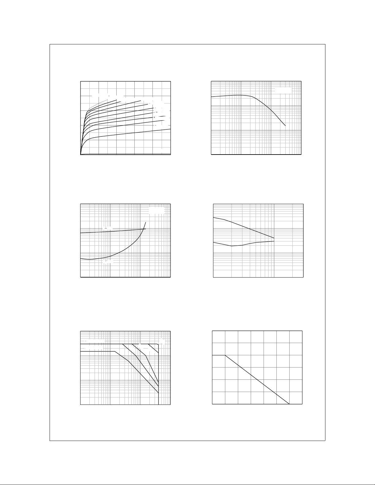
Typical Characteristics
KSE13003
IB = 450mA
IB = 400mA
IB = 350mA
IB = 300mA
IB = 250mA
IB = 200mA
IB = 150mA
IB = 100mA
IB = 50mA
IB = 0mA
2.0
IB = 500mA
1.6
1.2
0.8
[A], COLLECTOR CURRENT
C
0.4
I
0.0
012345
VCE[V], COLLECTOR-EMITTER VOLTAGE
100
10
1
, DC CURRENT GAIN
FE
h
0.1
0.01 0.1 1 10
IC[A], COLLECTOR CURRENT
Figure 1. Static Characteristic Figure 2. DC current Gain
10
1
0.1
(sat)[V], SATURATION VOLTAGE
CE
(sat), V
BE
V
0.01
0.01 0.1 1 10
VBE(sat)
VCE(sat)
IC[A], COLLECTOR CURREN T
IC = 4 I
B
10
1
s], TIME
µ
[
F
, t
0.1
STG
t
0.01
0.1 1
t
t
F
IC[A], COLLECTOR CURRENT
VCE = 2V
STG
Figure 3. Base-Emitter Saturation Voltage
Collector-Emitter Saturation Voltage
10
ICMAX. (pulse)
IC MAX. (DC)
1
0.1
[A], COLLECTO R CURRENT
C
I
0.01
1 10 100 1000
VCE[V], COLLECTOR-E MI T TE R VOLT A GE
Figure 5. Safe Operating Area Figure 6. Power Derating
©2002 Fairchild Semiconductor Corporation
Figure 4. Switching Time
10
µ
1ms
5ms
s
100
µ
s
30
25
20
15
10
[W], POWER DISSIPATION
C
P
5
0
0 255075100125150175
TC[oC], CASE TEMPERATURE
Rev. B1, December 2002
 Loading...