

Fairchild Semiconductor DM74AS161N, DM74AS161M Datasheet
April 1984
Revised March 2000
DM74AS161 • DM74AS163
Synchronous 4-Bit Counter with Asynchronous Clear •
Synchronous 4-Bit Counter
DM74AS161 • DM74AS163 Synchronous 4-Bit Counter with Asynchronous Clear • Synchronous 4-Bit Counter
General Description
These synchronous presetta ble counters feature an internal carry look ahead for app lication in hig h speed co unting
designs. The DM74AS161 and DM74AS163 are 4-bit
binary counters. The DM74AS161 clear asynchronously,
while the DM74AS163 cle ar synchron ously. The carry output is decoded to pr event spikes during normal count ing
mode of operation. Synchronous operati on is provided by
having all flip-flop s clocked simultane ously so that o utputs
change coincident wit h each other when so inst ructed by
count enable inputs and internal gating. This mode of operation eliminates the output counting spikes which are normally associated with asynchronous (ripple clock)
counters. A buffered clock inpu t triggers the four flip-f lops
on the rising (positive-going) edge of the clock input waveform.
These counters are fully programmable, that is, the outputs
may each be preset to either level. As presetting is synchronous, setting up a low level at the LOAD
the counter and ca uses the outputs to agre e with set up
data after the next clock pulse regard less of the levels of
enable input. LOW-to-HIG H transitions at the L OAD
are perfectly accepta ble regardless of the l ogic levels on
the clock or enable inputs.
The DM74AS161 clear function is asynchronous. A low
level at the clear input sets all four of the flip-flop outputs
LOW regardless of the levels of clock, load or enable
inputs. This counter is provi ded with a clear on power-up
feature. The DM74AS163 clear function is synchronous;
and a low level at the clear input sets all four of the flip-flop
outputs LOW after the next cl ock pulse, regardless of the
levels of enable in puts. This sync hronous c lear allows t he
count length to be m odified easily, as decoding the maximum count desired can be accomplished with one external
NAND gate. The gate output is connected to the clear input
to synchronously clear the counter to all LOW outputs.
LOW-to-HIGH transitions at the clear input of the
DM74AS163 is also permissible regardless of the levels of
logic on the clock, enable or load inputs.
input disables
input
The carry look ahead circuitry provides for cascading
counters for n bit synchronous application without additional gating. Instrumental in accomplishing this function
are two count-enabl e inputs (P and T) and a ripple carr y
output. Both count-enable in puts must be HIGH to count.
The T input is fed forward to ena ble th e ripp l e carr y out put .
The ripple carry output thus enabled will produce a high
level output pulse w ith a duration approxim ately equal to
the high level portion of QA output. This high level overflow
ripple carry pulse can be used to enable successive cascaded stages. HIGH-to-LOW level transitions at the enable
P or T inputs of the DM74AS16 1 and DM74AS163, may
occur regardless of the logic level on the clock.
The DM74AS1 61 and DM74AS163 feature a fully independent clock circuit. Change s made to con trol inputs (en able
P or T, or load) that will modify the operating mode will
have no effect until clo cking occurs. The function of the
counter (whether enab led, disabled, loading or counting)
will be dictated solely by the conditions meeting the stable
set-up and hold times.
Features
■ Switching specifications at 50 pF
■ Switching specifications guaranteed over full tempera-
ture and V
■ Advanced oxide-isolated, ion-implanted Schottky TTL
process
■ Functionally and pin-for-pin compatible with Schottky
and low power Schottky TTL counterpart
■ Improved AC performance over Scho ttky and low power
Schottky counterparts
■ Synchronously programmable
■ Internal look ahead for fast counting
■ Carry output for n-bit cascading
■ Synchronous counting
■ Load control line
■ ESD inputs
CC
range
Ordering Code:
Order Number Package Number Package Description
DM74AS161M M16A 16-Lead Small Outline Integrated Circuit (SOIC), JEDEC MS-012, 0.150 Narrow
DM74AS161N N16E 16-Lead Plastic Dual-In-Line Package (PDIP), JEDEC MS-001, 0.300 Wide
DM74AS163M M16A 16-Lead Small Outline Integrated Circuit (SOIC), JEDEC MS-012, 0.150 Narrow
DM74AS163N N16E 16-Lead Plastic Dual-In-Line Package (PDIP), JEDEC MS-001, 0.300 Wide
Devices also availab le in Tape and Reel. Specify by appending th e s uffix let t er “X” to the ordering cod e.
© 2000 Fairchild Semiconductor Corporation DS006291 www.fairchildsemi.com
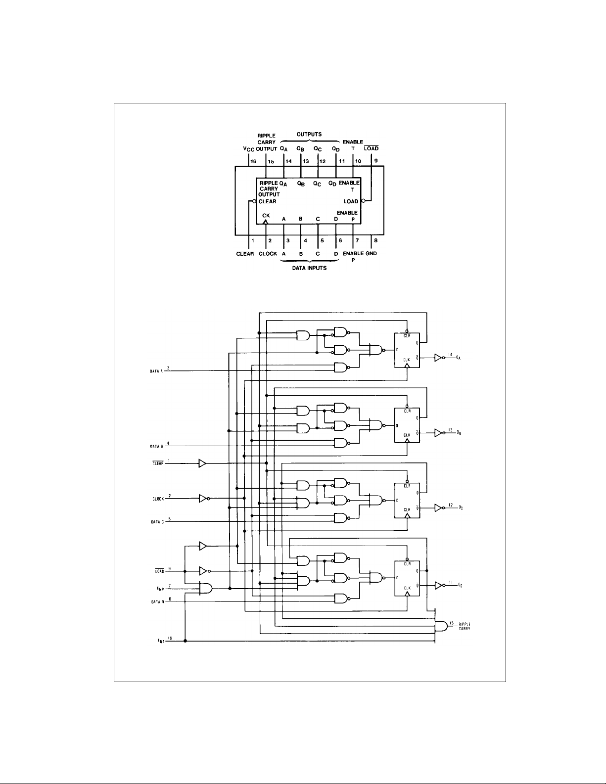
Connection Diagram
DM74AS161 • DM74AS163
Logic Diagrams
DM74AS161
www.fairchildsemi.com 2
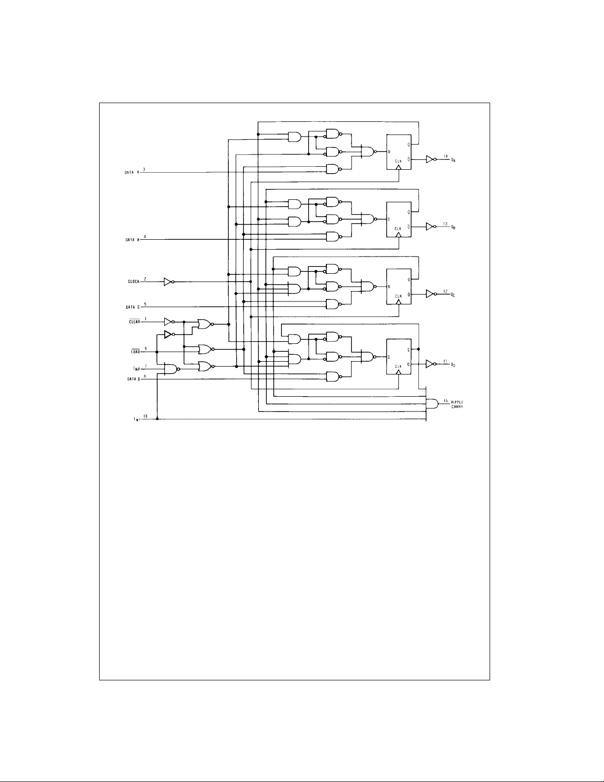
DM74AS163
DM74AS161 • DM74AS163
3 www.fairchildsemi.com
 Loading...