

Page 1
AMPLIFICADOR MULTICANAL
MEHRKANALVERSTÄRKER
AMPLIFICATEUR MULTICANAL
MULTICHANNEL AMPLIFIER
AMPLIFICATORE MULTICANALE
AMPLIFICADOR MULTI-CHANNEL
E
D
F
GB
I
P
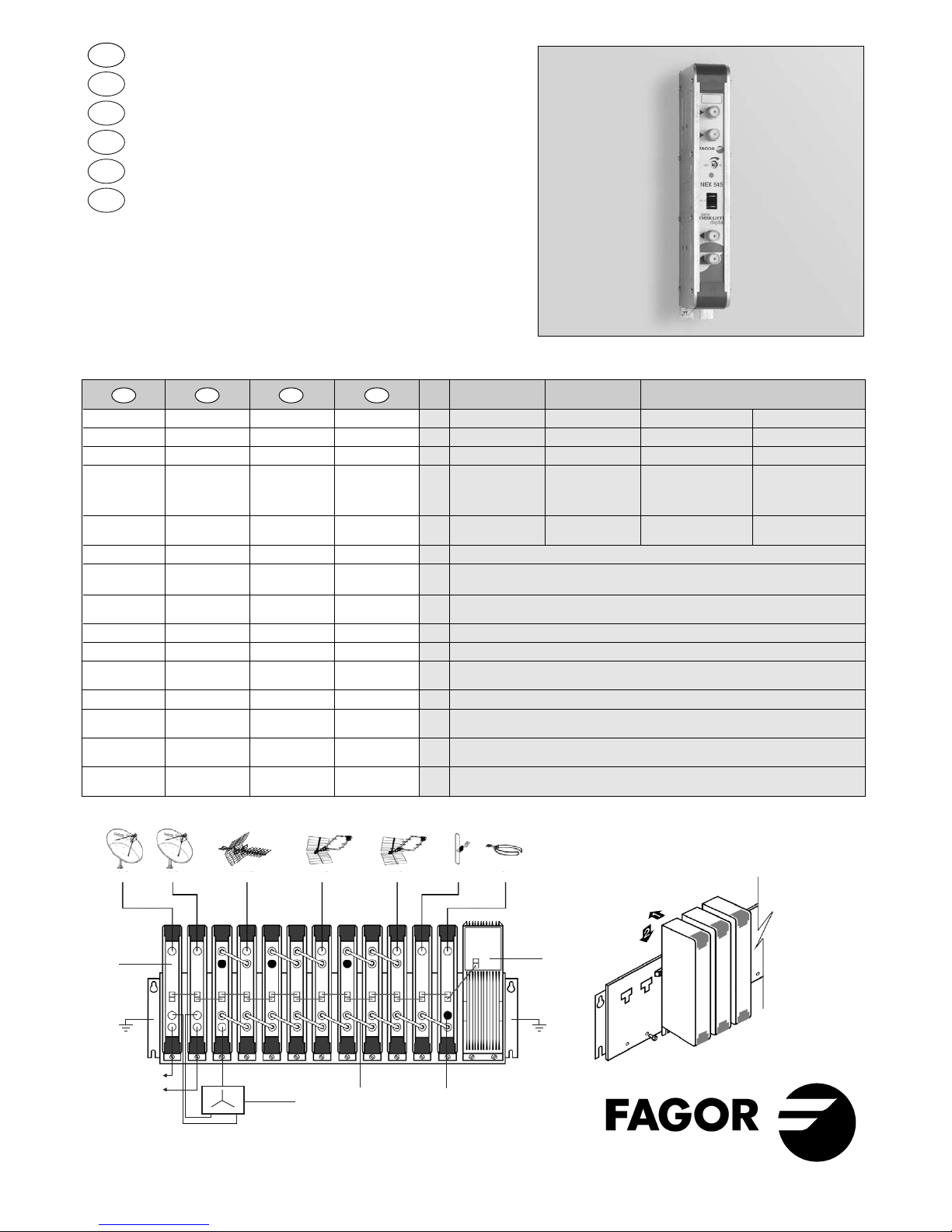
NEX 545 MULTICANAL
SAT
IFA IFA NEX NEX NEX NEX NEX NEX NEX NEX NEX NEX
SPS
Ref. 69523
SAT UHF UHF UHF DAB FM
Ref. 39204
OUTPUT 1
OUTPUT 2
Ref. 85028 Ref. 84034 Ref. 84011
* B/G standard
E
D
F
GB
Referencia Reeferenz Réference Reference Bicanal Tricanal Tetracanal Pentacanal
Canales Känale Canaux Channels — —
66 ÷ 69 65 ÷ 69
Ancho de banda
Frequenzbereich
Bandes couvertes Bandwidth
MHz 16 24 32 40
Selectividad *
Selektivität * Sélectivité * Selectivity *
@ N = ch 65 @ N = ch 64
PVN÷PAN-1 PVN÷PAN-1 PVN÷PAN-1 PVN÷PAN-1 — — 16 16
PV
N
÷PAN-2 PVN÷PAN-2 PVN÷PAN-2 PVN÷PAN-2
dB
30 30 — —
PA
N
÷PVN+2 PAN÷PVN+2 PAN÷PVN+2 PAN÷PVN+2 30 30 — —
Nivel máx. de Max. Niveau
de
Max. output
112 (2 Ch AM-TV) 111 (3 Ch AM-TV) 109 (4 Ch AM-TV) 108 (5 Ch AM-TV)
salida
Ausgangspegel sortie max. level
dBμV
109
(2 Ch COFDM)
107
(3 Ch COFDM)
106
(4 Ch COFDM)
105
(5 Ch COFDM)
Ganancia Verstärkung Gain Gain dB 50
Regulación de Regulierung der
Plage de Gain
ganancia Verstärkung
réglage de gain adjustment
dB 30
Pérdidas de
Rückflussdämpfung Adaptation Return losses
retorno
dB 9
Figura de ruido Rauschmaß
Facteur de bruit
Noise figure
dB 11
Consumo (24 V
DC
) Stromverbrauch
Consommation Current Drawn
mA 110
Dimensiones de
Ausmasse
Dimensions du Packing
embalaje conditionnement dimensions
mm 195 x 70 x 32
Peso Gewicht Poid Weight Kg 0,45
Impedancia de
Eingangs-/Ausgangs Impédance Input-Output
entrada y salida impedanz
d’entrée-
sortie impedance
Ω 75
Conectores de
Eingangs-/Ausgangs Connecteurs Input-Output
entrada y salida stecker
d’entrée-
sortie connectors
F (h)
Temperatura de
Betriebstemperatur
Température de Operating
funcionamiento fonctionnement temperature
ºC 0 ÷ 50
NEX 545 NEX 545 NEX 545
Page 2

INSTALACIÓN Y PUESTA EN MARCHA
•
Sujetar los módulos en el bastidor según el
ejemplo de aplicación, colocando los módulos
de frecuencias más bajas cerca de la fuente de
alimentación, y los módulos de mayor frecuencia
cerca de la salida de señal.
•
Realizar la distribución de señal en la(s) entradas
mediante el puente coaxial F-F (Ref. 84034) y
cargar la(s) salida(s) libre(s) con 75 Ω (Ref. 84011).
•
Unir las Salidas de RF (5) mediante el puente
coaxial F-F, y cargar con 75 Ω la salida libre.
•
Conectar los cables de bajada de las antenas en
las entradas correspondientes (1).
•
Conectar la Alimentación entre los módulos y la
Fuente de alimentación SPS.
•
Ajustar el nivel de salida de cada amplificador
mediante el regulador de nivel de salida (2).
INSTALLATION UND INBETRIEBNAHME
•
Die Module am Rahmen befestigen, wie im
Anwendungsbeispiel angegeben: Beginnend von
rechts nach links, zuerst das Netzteil, dann die
Module der niedrigen Frequenzen, und die Module
der höheren Frequenzen in der Nähe des.
•
Die Signalverteilung am Eingang (an den
Eingängen) wird mit Hilfe des koaxialen Bügels
F-F (Ref. 84034) vorgenommen. Jeder nicht
belegte Ausgang wird mit 75 Ohm. (Ref. 84011)
abgeschlossen.
•
Die RF-Ausgänge (5) mit Hilfe des koaxialen
Bügels F-F miteinander verbinden und den freien
Ausgang mit 75 Ohm abschließen.
•
Die Ableitungskabel der Antennen werden an die
entsprechenden Eingänge (1) angeschlossen.
•
Die Stromversorgung zwischen den Modulen und
dem Netzteil SPS anbringen.
•
Der Ausgangspegel jedes einzelnen Verstärkers
wird mit Hilfe des Reglers für den Ausgangspegel
eingestellt.
INSTALLATION ET MISE EN MARCHE
•
Fixer les modules au bâti selon l’exemple
d’application en plaçant les modules correspndants
aux fréquences les plus bas a cote l’alimentation et
ceux des fréquences le plus hauts a coté de la sortie.
•
Faire la distribution de signal de l’entrée (des
entrées) à l’aide du pont coaxial F-F (Ref. 84034)
et charger la(les) sortie(s) libre(s) à 75 Ω
(Ref. 84011).
•
Unir les sorties de RF (5) à l’aide du pont coaxial
F-F et charger à 75 Ω la sortie libre.
•
Brancher les câbles de descente des antennes aux
entrées correspondantes (1).
•
Raccorder l’alimentation entre les modules et la
source d’alimentation SPS.
•
Régler son niveau de sortie à l’aide du régulateur
de Niveau de Sortie (2).
INSTALLATION AND SETUP
•
Fix the modules on the frame following the
application example by placing the lower frequency
modules near to the power supply and the higher
frequency modules near to the signal output.
•
Carry out the signal distribution form the input(s)
by means of the F-F coaxial bridge (Ref. 84034)
and load the free output(s) with 75 Ω (Ref. 84011).
•
Join the RF Outputs (5) by means of the F-F coaxial
bridge and load with 75 Ω the free output.
•
Connect the leads from the antennas to the
corresponding inputs (1).
•
Connect the Supply between the modules and the
SPS Power Supply.
•
Adjust the output level of each amplifier by means
of the output level control (2).
E
D
GB
GB
D
I
F
P
E
F
JJK / FAGOR . NEX 500 MULTICANAL 4 I / 01-07 • 02175064
1
2
3
4
5
1. Entrada RF
2. Nivel
3. LED de Alimentación
4. Alimentación +24v
5. Salida RF
1. Entrée RF
2. Niveau
3. Témoin d’alimentation
4. Alimentation +24v
5. RF sortie
1. RF input
2. Level
3. Supply LED
4. Supply +24v
5. RF Output
1. Ingresso RF
2. Livello
3. LED di alimentazione
4. Alimentazione +24v
5. Uscita RF
1. Entrada RF
2. Nivel
3. LED de Alimentação
4. Alimentação +24v
5. Saida RF
1. RF-Eingang
2. Stand
3. LED Stromversorgung
4. Stromversorgung +24v
5. RF-Ausgang
CONTROLES / REGLER / COMMANDES / CONTROLS / CONTROLLI / CONTROLES
Fagor Electrónica, S.Coop.
San Andrés, s/n.
E-20500 Mondragón (Spain)
Tel. +34 43 712526
Fax +34 43 712893
E- mail: rf.sales@fagorelectronica.es
www.fagorelectronica.com
 Loading...