

Page 1

FAGOR 8025/8030 CNC
Models: T, TG, TS
INSTALLATION MANUAL
Ref. 9707 (in)
Page 2

ABOUT THE INFORMATION IN THIS MANUAL
This manual is addressed to the machine manufacturer.
It includes the necessary information for new users as well as advanced subjects for
those who are already familiar with the 8025 CNC.
It may not be necessary to read this whole manual. Consult the list of "New Features
and Modifications" and the appendix related to the machine parameters. Practically
all of them are cross referenced indicating the chapter and section of the manual
where they are described.
This manual explains all the functions of the 8025 CNC family. Consult the
Comparison Table for the models in order to find the specific ones offered by your
CNC.
To install the CNC onto your machine, we suggest that you consult the appendix
regarding the enclosures required to mount the CNC as well as chapter 1 (CNC
configuration) which indicates the CNC dimensions and details the pin-out of its
connectors.
If your CNC has an integrated PLC (PLCI), the I/O pin-out is different. Therefore,
the PLCI manual must also be consulted.
Chapter 2 (Power and Machine Interface) shows how to connect the CNC to A.C.
power (Mains) and to the electrical cabinet.
To adapt the CNC to the machine, set the CNC machine parameters. Consult chapters
3, 4 and 5 as well as the appendix concerning machine parameters.
There are 2 appendices; one where the parameters are ordered by subject and the
other one where the parameters are in numerical order.
Both appendices offer cross references indicating the section of the manual describing
each parameter.
When explaining each parameter in detail, chapters 3, 4 and 5, they sometimes refer
to chapter 6 (Concepts) where some of them are dealt with in further detail indicating
how to perform various adjustments of the CNC-machine interface.
Once all machine parameters are set, we suggest that you write their settings down
on the charts provided for this purpose in the appendix on "Machine Parameter Setting
Chart".
There is also an appendix on error codes which indicates some of the probable reasons
which could cause each one of them.
Also, if you wish this CNC to communicate with other FAGOR products, you must
use the Fagor Local Area Network (LAN). To do that, refer to the manual on FAGOR
LAN.
Notes
: The information described in this manual may be subject to variations due
to technical modifications.
FAGOR AUTOMATION, S. Coop. Ltda. reserves the right to modify the
contents of this manual without prior notice.
Page 3

INDEX
Section Page
Comparison Table for lathe model 8025 CNCs ........................................................ix
New features and modifications ...............................................................................xiii
INTRODUCTION
Declaration of Conformity ........................................................................................3
Safety Conditions ...................................................................................................... 4
Warranty Terms ........................................................................................................7
Material Returning Terms .........................................................................................8
Additional Remarks .................................................................................................. 9
Fagor Documentation for the 800T CNC .................................................................11
Manual Contents ....................................................................................................... 12
Chapter 1 CONFIGURATION OF THE CNC
1.1 8025 CNC ..................................................................................................................1
1.2 Dimensions and installation of the 8025 CNC ........................................................ 2
1.2 8030 CNC ..................................................................................................................3
1.2.1 Central Unit of the 8030 CNC .................................................................................4
1.2.1.1 Keyboard connector ..................................................................................................6
1.2.1.2 Video connector ........................................................................................................8
1.2.2 Monitor/Keyboard of the 8030 CNC........................................................................9
1.2.2.1 Dimensions of the monitor/keyboard .......................................................................9
1.2.2.2 Elements of the monitor/keyboard ...........................................................................10
1.2.2.3 Connector and and monitor/keyboard interface ....................................................... 11
1.2.3 Operator Panel of the 8030 CNC ............................................................................. 12
1.3 Connectors and 8025/8030 interface ........................................................................13
1.3.1 Connectors A1, A2, A3, A4 .....................................................................................15
1.3.1.1 Dip-switches for connectors A1, A2, A3, A4 ..........................................................17
1.3.2 Connector A5 ............................................................................................................18
1.3.2.1 Dip-switches for connector A5 ................................................................................. 19
1.3.3 Connector A6 ............................................................................................................20
1.3.4 RS232C connector .....................................................................................................21
1.3.5 RS485 connector .......................................................................................................24
1.3.5.1 Recommended cable for the RS485 .........................................................................24
1.3.6 Connector I/O 1 .........................................................................................................25
1.3.6.1 Inputs of connector I/O 1 .........................................................................................26
1.3.6.2 Outputs of connector I/O 1 ....................................................................................... 29
1.3.7 Connector I/O 2 .........................................................................................................31
1.3.7.1 Outputs of connector I/O 2 ....................................................................................... 32
Page 4

Section
Chapter 2 POWER AND MACHINE INTERFACE
2.1 Power interface .........................................................................................................1
2.1.1 Internal power supply ................................................................................................ 1
2.2 Machine interface ......................................................................................................2
2.2.1 General considerations ..............................................................................................2
2.2.2 Digital outputs ...........................................................................................................4
2.2.3 Digital inputs .............................................................................................................4
2.2.4 Analog outputs...........................................................................................................5
2.2.5 Feedback inputs .........................................................................................................5
2.3 Set-up.........................................................................................................................6
2.3.1 General considerations ..............................................................................................6
2.3.2 Precautions.................................................................................................................6
2.3.3 Connection ................................................................................................................. 7
2.3.4 System input/output test ............................................................................................8
2.4 Emergency input/output connection ......................................................................... 10
Chapter 3 MACHINE PARAMETERS
3.1 Introduction ...............................................................................................................1
3.2 Operation with parameter tables................................................................................3
3.3 General machine parameters .....................................................................................4
3.3.1 Machine parameters related to axes configuration....................................................5
3.3.2 Input/output parameters ............................................................................................. 7
3.3.3 Handwheel parameters...............................................................................................10
3.3.4 Touch probe parameters ............................................................................................12
3.3.5 Tool parameters .........................................................................................................13
3.3.6 Parameters related to the emergency subroutine.......................................................15
3.3.7 Machine parameters for the RS232C serial line .......................................................16
3.3.8 Display related parameters ........................................................................................18
3.3.9 Jog-mode related parameters .....................................................................................19
3.3.10 Operating-mode related parameters...........................................................................21
Page
Chapter 4 MACHINE PARAMETERS FOR THE AXES
4.1 Parameters related to axis resolution.........................................................................2
4.2 Parameters for axis analog outputs ...........................................................................5
4.3 Parameters for the travel limits of the axes ..............................................................6
4.4 Machine parameters for the leadscrews ....................................................................7
4.4.1 Leadscrew backlash ...................................................................................................7
4.4.2 Leadscrew error .........................................................................................................8
4.5 Machine parameters for axis feedrates ...................................................................... 11
4.6 Machine parameters for axis control ......................................................................... 13
4.7 Machine parameters for machine reference zero ......................................................15
4.8 Parameters for acc/dec of the axes ............................................................................ 18
4.8.1 Linear acc./dec...........................................................................................................18
4.8.2 Bell-shaped acc./dec. .................................................................................................19
4.8.3 Feed-forward gain .....................................................................................................20
4.9 Parameters for the live or synchronized tool ............................................................ 21
4.10 Special machine parameters ......................................................................................23
Page 5

Section Page
Chapter 5 SPINDLE MACHINE PARAMETERS
5.1 Machine parameters for spindle speed range change ..............................................2
5.2 Machine parameters for analog spindle speed output .............................................4
5.3 Machine parameters for spindle speed output in BCD ............................................5
5.4 Machine parameters for spindle control ...................................................................7
5.4.1 Parameters related to spindle orientation (M19) ..................................................... 9
Chapter 6 CONCEPTS
6.1 Axes and coordinate systems ....................................................................................1
6.1.1 Nomenclature and selection of the axes .................................................................. 1
6.2 Feedback systems ......................................................................................................2
6.2.1 Counting frequency limits ........................................................................................3
6.3 Axis resolution ..........................................................................................................4
6.4 Adjustment of the axes .............................................................................................13
6.4.1 Adjustment of the drift (offset) and maximum feedrate (G00)...............................14
6.4.2 Gain adjustment ........................................................................................................ 16
6.4.3 Proportional gain adjustment....................................................................................17
6.4.3.1 Calculation of K1, K2 and gain break-point ............................................................19
6.4.4 Feed-Forward gain adjustment .................................................................................21
6.4.4.1 Calculation of feed-forward gain .............................................................................21
6.4.5 Leadscrew error compensation .................................................................................22
6.5 Reference systems.....................................................................................................25
6.5.1 Reference points ........................................................................................................25
6.5.2 Machine reference (home) search .............................................................................26
6.5.3 Adjustment on systems without coded Io ................................................................27
6.5.3.1 Machine reference point (Home) adjustment ...........................................................27
6.5.3.2 Considerations ........................................................................................................... 28
6.5.4 Adjustment on axis with coded Io ............................................................................29
6.5.4.1 Scale offset adjustment.............................................................................................29
6.5.4.2 Considerations ........................................................................................................... 30
6.5.5 Software travel limits for the axes ...........................................................................31
6.6 Auxiliary functions M, S, T ..................................................................................... 32
6.6.1 Decoded M function table ........................................................................................33
6.6.2 M, S, T function transfer ..........................................................................................35
6.6.3 M, S, T function transfer using the M-done signal .................................................36
6.7 Spindle.......................................................................................................................38
6.8 Spindle speed range change ......................................................................................41
6.9 Spindle control ..........................................................................................................43
6.10 Tools..........................................................................................................................44
6.11 Live/synchronized tool ..............................................................................................45
6.11.1 Live tool ....................................................................................................................45
6.11.2 Synchronized tool .....................................................................................................46
6.11.2.1 Application examples for the synchronized tool ..................................................... 47
6.12 "C" axis .....................................................................................................................48
6.12.1 Adjustment of the "C" axis .......................................................................................48
Page 6

Section Page
APPENDICES
A Technical characteristics of the CNC ...................................................................... 2
B Enclosures................................................................................................................. 5
C Recommended Probe connection diagrams .............................................................. 6
D CNC inputs and outputs........................................................................................... 7
E 2-digit BCD coded "S" output conversion table ..................................................... 8
F Machine parameter summary chart .......................................................................... 9
G Sequential machine parameter list ........................................................................... 14
H Machine parameter setting chart .............................................................................. 20
I Decoded "M" function setting chart......................................................................... 22
J Leadscrew error compensation setting chart ........................................................... 23
K Maintenance ............................................................................................................. 24
ERROR CODES
Page 7

COMPARISON TABLE
FOR
LATHE MODEL
FAGOR 8025/8030 CNCs
Page 8
TECHNICAL DESCRIPTION
T TG TS
INPUTS/OUTPUTS
Feedback inputs. ............................................................................................. 6 6 6
Probe input .................................................................................................. x x x
Square-wave feedback signal multiplying factor, x2/x4 ................................... x x x
Sine-wave feedback signal multiplying factor, x2/x4/10/x20........................... x x x
Maximum counting resolution 0.001mm/0.001°/0.0001inch........................... x x x
Analog outputs (±10V) for axis servo drives .................................................... 4 4 4
Spindle analog output (±10V) ......................................................................... 1 1 1
Live tool .................................................................................................. 1 1 1
AXIS CONTROL
Axes involved in linear interpolations ............................................................. 3 3 3
Axes involved in circular interpolations .......................................................... 2 2 2
Electronic threading ........................................................................................ x x x
Spindle control ................................................................................................ x x x
Software travel limits....................................................................................... x x x
Spindle orientation .......................................................................................... x x x
PROGRAMMING
Part Zero preset by user.................................................................................... x x x
Absolute/incremental programming................................................................. x x x
Programming in cartesian coordinates.............................................................. x x x
Programming in polar coordinates ................................................................... x x x
Programming by angle and cartesian coordinate .............................................. x x x
Linear axes ................................................................................ 4 4 4
Rotary axes................................................................................ 2 2 2
Spindle encoder ......................................................................... 1 1 1
Electronic handwheel ................................................................ 1 1 1
Third axis as "C" axis ................................................................. x
Synchronized tool ...................................................................... x
COMPENSATION
Tool radius compensation ............................................................................... x x x
Tool length compensation............................................................................... x x x
Leadscrew backlash compensation .................................................................. x x x
Leadscrew error compensation......................................................................... x x x
DISPLAY
CNC text in Spanish, English, French, German and Italian ............................... x x x
Display of execution time................................................................................ x x x
Piece counter .................................................................................................. x x x
Graphic movement display and part simulation ............................................... x x
Tool tip position display ................................................................................. x x x
Geometric programming aide........................................................................... x x x
COMMUNICATION WITH OTHER DEVICES
Communication via RS232C........................................................................... x x x
Communication via DNC ................................................................................ x x x
Communication via RS485 (FAGOR LAN)...................................................... x x x
ISO program loading from peripherals.............................................................. x x x
OTHERS
Parametric programming.................................................................................. x x x
Model digitizing ............................................................................................. x
Possibility of an integrated PLC ...................................................................... x x x
Page 9
PREPARATORY FUNCTIONS
T TG TS
AXES AND COORDINATES SYSTEMS
Part measuring units. Millimeters or inches (G70,G71)..................................... x x x
Absolute/incremental programming (G90,G91)................................................ x x x
Independent axis (G65) ................................................................................... x x x
REFERENCE SYSTEMS
Machine reference (home) search (G74) ........................................................... x x x
Coordinate preset (G92)................................................................................... x x x
Zero offsets (G53...G59)................................................................................... x x x
Polar origin offset (G93) .................................................................................. x x x
Store current part zero (G31) ............................................................................ x x x
Recover stored part zero (G32)......................................................................... x x x
PREPARATORY FUNCTIONS
Feedrate F .................................................................................................. x x x
Feedrate in mm/min. or inches/min. (G94)........................................................ x x x
feedrate in mm/revolution or inches/revolution (G95)...................................... x x x
Programmable feed-rate override (G49)............................................................ x x x
Spindle speed (S)............................................................................................. x x x
Spindle speed in rpm (G97) ............................................................................. x x x
Constant Surface Speed (G96) ......................................................................... x x x
S value limit when working at constant surface speed (G92)............................ x x x
Tool and tool offset selection (T) ..................................................................... x x x
Activate "C" axis in degrees (G14) ................................................................... x
Main plane C-Z (G15) ..................................................................................... x
Main plane C-X (G16) ..................................................................................... x
AUXILIARY FUNCTIONS
Program stop (M00)......................................................................................... x x x
Conditional program stop (M01) ..................................................................... x x x
End of program (M02) ..................................................................................... x x x
End of program with return to first block (M30) ............................................... x x x
Clockwise spindle start (M03) ......................................................................... x x x
Counter-clockwise spindle start (M04) ............................................................ x x x
Spindle stop (M05).......................................................................................... x x x
Spindle orientation (M19) ............................................................................... x x x
Spindle speed range change (M41, M42, M43, M44)....................................... x x x
Tool change with M06 .................................................................................... x x x
Live tool (M45 S) ............................................................................................ x x x
Synchronized tool (M45 K) ............................................................................. x
PATH CONTROL
Rapid traverse (G00)........................................................................................ x x x
Linear interpolation (G01)............................................................................... x x x
Circular interpolation (G02,G03) ..................................................................... x x x
Circular interpolation with absolute center coordinates (G06).......................... x x x
Circular path tangent to previous path (G08) ................................................... x x x
Arc defined by three points (G09) .................................................................... x x x
Tangential entry (G37) .................................................................................... x x x
Tangential exit (G38) ...................................................................................... x x x
Controlled radius blend (G36) ......................................................................... x x x
Chamfer (G39)................................................................................................. x x x
Electronic threading (G33) .............................................................................. x x x
ADDITIONAL PREPARATORY FUNCTIONS
Dwell (G04 K) ................................................................................................. x x x
Round and square corner (G05, G07) ............................................................... x x x
Scaling factor (G72)......................................................................................... x x x
Single block treatment (G47, G48)................................................................... x x x
User error display (G30)................................................................................... x x x
Automatic block generation (G76)................................................................... x
Communication with FAGOR Local Area Network (G52)................................. x x x
Page 10

T TG TS
COMPENSATION
Tool radius compensation (G40,G41,G42) ....................................................... x x x
Loading of tool dimensions into internal tool table (G50, G51) ....................... x x x
CANNED CYCLES
Pattern repeat (G66)......................................................................................... x x x
Roughing along X (G68) ................................................................................. x x x
Roughing along Z (G69) ................................................................................. x x x
Straight section turning (G81) ......................................................................... x x x
Straight section facing (G82) ........................................................................... x x x
Deep hole drilling (G83).................................................................................. x x x
Circular section turning (G84) ......................................................................... x x x
Circular section facing (G85)........................................................................... x x x
Longitudinal threadcutting (G86).................................................................... x x x
Face threadcutting (G87) ................................................................................. x x x
Grooving along X (G88) .................................................................................. x x x
Grooving along Z (G89) .................................................................................. x x x
PROBING
Probing (G75).................................................................................................. x x x
Tool calibration canned cycle (G75N0) ........................................................... x
Probe calibration canned cycle (G75N1).......................................................... x
Part measuring canned cycle along X (G75N2) ................................................ x
Part measuring canned cycle along Z (G75N3)................................................. x
Part measuring canned cycle with tool compensation along X (G75N4) ........... x
Part measuring canned cycle with tool compensation along Z (G75N5)............ x
SUBROUTINES
Number of standard subroutines....................................................................... 99 99 99
Definition of a standard subroutine (G22) ........................................................ x x x
Call to a standard subroutine (G20) ................................................................. x x x
Number of parametric subroutines ................................................................... 99 99 99
Definition of a parametric subroutine (G23) ..................................................... x x x
Call to a parametric subroutine (G21) .............................................................. x x x
End of standard or parametric subroutine (G24) ............................................... x x x
JUMP OR CALL FUNCTIONS
Unconditional jump/call (G25)........................................................................ x x x
Jump or call if zero (G26)................................................................................. x x x
Jump or call if not zero (G27)........................................................................... x x x
Jump or call if smaller (G28) ............................................................................ x x x
Jump or call if greater (G29)............................................................................. x x x
Page 11
NEW FEATURES
AND
MODIFICATIONS
Date: March 1991 Software Version: 2.1 and newer
FEATURE MODIFIED MANUAL & SECTION
The home searching direction is set by machine Installation Manual Section 4.7
parameter P618(5,6,7,8)
The 2nd home searching feedrate is set by Installation Manual Section 4.7
machine parameter P807...P810
New resolution values 1, 2, 5 and 10 for sine-wave Installation Manual Section 4.1
feedback signals P619(1,2,3,4)
Access to PLCI registers from the CNC Programming Manual G52
Date: June 1991 Software Version: 3.1 and newer
FEATURE MODIFIED MANUAL AND SECTION
New function: F36. It takes the value of the Programming Manual Chapter 13
selected tool number
G68 and G69 canned cycles modified. if P9=0 Programming Manual Chapter 13
it runs another final roughing pass
Date: September 1991 Software Version: 3.2 and newer
FEATURE MODIFIED MANUAL AND SECTION
Subroutine associated with the T function Installation Manual Section 3.3.5
G68 and G69 canned cycles modified. Programming Manual Chapter 13
P9 can now have a negative value
Page 12

Date: March 1992 Software Version: 4.1 and newer
FEATURE MODIFIED MANUAL AND SECTION
Bell-shaped ACC./DEC. Installation Manual Section 4.8
It is now possible to enter the sign of the Installation Manual Section 4.4
leadscrew backlash for each axis P620(1,2,3,4)
Independent axis movement execution Programming Manual G65
It is now possible to work at Constant Surface Installation Manual Section 3.3.9
Speed in JOG mode P619(8)
Date: July 1992 Software Version: 4.2 and newer
FEATURE MODIFIED MANUAL AND SECTION
Synchronisation with independent axis P621(4) Installation Manual Section 3.3.10
Date: July 1993 Software Version: 5.1 and newer
FEATURE MODIFIED MANUAL AND SECTION
Linear & Bell-shaped acc./dec. ramp combination Installation Manual Section 4.8
Spindle acc/dec control. P811 Installation Manual Section 5.
The subroutine associated with the tool Installation Manual Section 3.3.5
is executed before the T function. P617(2)
G68 and G69 cycles modified. If P10 <> 0, Programming Manual Chapter 13
it runs a final roughing pass before the
finishing pass
When having only one spindle range, if G96 is Programming Manual Chapter 6
executed without any range being selected, the
CNC will automatically select it.
8030 CNC with VGA Monitor Installation Manual Chapter 1
Date: March1995 Software Version: 5.3 and newer
FEATURE MODIFIED MANUAL AND SECTION
Management of semi-absolute feedback devices Installation Manual Sections 4.7 & 6.5.
(with coded Io)
Spindle inhibit by PLC Installation Manual Section 3.3.10
Handwheel managed by PLC Installation Manual Section 3.3.3
Simulation of the "rapid JOG" key from PLC PLCI Manual
Initialization of machine parameters in case of
memory loss.
Page 13
Atention:
INTRODUCTION
Before starting up the CNC, carefully read the instructions of Chapter
2 in the Installation Manual.
The CNC must not be powered-on until verifying that the machine
complies with the "89/392/CEE" Directive.
Introduction - 1
Page 14

DECLARATION OF CONFORMITY
Manufacturer: Fagor Automation, S. Coop.
Barrio de San Andrés s/n, C.P. 20500, Mondragón -Guipúzcoa- (ESPAÑA)
We hereby declare, under our responsibility that the product:
Fagor 8025 T CNC
meets the following directives:
SAFETY:
EN 60204-1 Machine safety. Electrical equipment of the machines.
ELECTROMAGNETIC COMPATIBILITY:
EN 50081-2 Emission
EN 55011 Radiated. Class A, Group 1.
EN 55011 Conducted. Class A, Group 1.
EN 50082-2 Immunity
EN 61000-4-2 Electrostatic Discharges.
EN 61000-4-4 Bursts and fast transients.
EN 61000-4-11Voltage fluctuations and Outages.
ENV 50140 Radiofrequency Radiated Electromagnetic Fields.
ENV 50141 Conducted disturbance induced by radio frequency fields.
As instructed by the European Community Directives on Low Voltage: 73/23/EEC,
on Machine Safety 89/392/EEC and 89/336/EEC on Electromagnetic Compatibility.
In Mondragón, on January 2nd, 1997
Introduction - 3
Page 15

SAFETY CONDITIONS
Read the following safety measures in order to prevent damage to personnel, to
this product and to those products connected to it.
This unit must only be repaired by personnel authorized by Fagor Automation.
Fagor Automation shall not be held responsible for any physical or material
damage derived from the violation of these basic safety regulations.
Precautions against personal damage
Module interconnection
Use the cables supplied with the unit.
Use proper Mains AC power cables
To avoid risks, use only the Mains AC cables recommended for this unit.
Avoid electrical overloads
In order to avoid electrical discharges and fire hazards, do not apply electrical voltage
outside the range selected on the rear panel of the Central Unit.
Ground connection
In order to avoid electrical discharges, connect the ground terminals of all the
modules to the main ground terminal. Before connecting the inputs and outputs of this
unit, make sure that all the grounding connections are properly made.
Before powering the unit up, make sure that it is connected to ground
In order to avoid electrical discharges, make sure that all the grounding connections
are properly made.
Do not work in humid environments
In order to avoid electrical discharges, always work under 90% of relative humidity
(non-condensing) and 45º C (113º F).
Do not work in explosive environments
In order to avoid risks, damage, do not work in explosive environments.
Precautions against product damage
Working environment
This unit is ready to be used in Industrial Environments complying with the directives
and regulations effective in the European Community
Fagor Automation shall not be held responsible for any damage suffered or caused
when installed in other environments (residential or homes).
Install the unit in the right place
Introduction - 4
It is recommended, whenever possible, to instal the CNC away from coolants,
chemical product, blows, etc. that could damage it.
Page 16

This unit complies with the European directives on electromagnetic compatibility.
Nevertheless, it is recommended to keep it away from sources of electromagnetic
disturbance such as.
- Powerful loads connected to the same AC power line as this equipment.
- Nearby portable transmitters (Radio-telephones, Ham radio transmitters).
- Nearby radio / TC transmitters.
- Nearby arc welding machines
- Nearby High Voltage power lines
- Etc.
Enclosures
The manufacturer is responsible of assuring that the enclosure involving the equipment
meets all the currently effective directives of the European Community.
Avoid disturbances coming from the machine tool
The machine-tool must have all the interference generating elements (relay coils,
contactors, motors, etc.) uncoupled.
Use the proper power supply
Use an external regulated 24 Vdc power supply for the inputs and outputs.
Grounding of the power supply
The zero volt point of the external power supply must be connected to the main ground
point of the machine.
Analog inputs and outputs connection
It is recommended to connect them using shielded cables and connecting their shields
(mesh) to the corresponding pin (See chapter 2).
Ambient conditions
The working temperature must be between +5° C and +45° C (41ºF and 113º F)
The storage temperature must be between -25° C and 70° C. (-13º F and 158º F)
Monitor enclosure
Assure that the Monitor is installed at the distances indicated in chapter 1 from the
walls of the enclosure.
Use a DC fan to improve enclosure ventilation.
Main AC Power Switch
This switch must be easy to access and at a distance between 0.7 m (27.5 inches) and
1.7 m (5.6 ft) off the floor.
Protections of the unit itself
It carries two fast fuses of 3.15 Amp./ 250V. to protect the mains AC input.
All the digital inputs and outputs have galvanic isolation via optocouplers between
the CNC circuitry and the outside.
They are protected by an external fast fuse (F) of 3.15 Amp./ 250V. against over
voltage and reverse connection of the power supply.
The type of fuse depends on the type of monitor. See the identification label of the
unit.
Introduction - 5
Page 17
Precautions during repair
Do not manipulate the inside of the unit
Only personnel authorized by Fagor Automation may manipulate the
inside of this unit.
Do not manipulate the connectors with the unit connected to AC
power.
Before manipulating the connectors (inputs/outputs, feedback, etc.)
make sure that the unit is not connected to AC power.
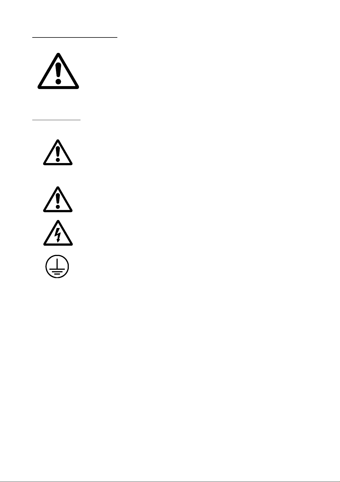
Safety symbols
Symbols which may appear on the manual
WARNING. symbol
It has an associated text indicating those actions or operations may hurt
people or damage products.
Symbols that may be carried on the product
WARNING. symbol
It has an associated text indicating those actions or operations may hurt
people or damage products.
"Electrical Shock" symbol
It indicates that point may be under electrical voltage
"Ground Protection" symbol
It indicates that point must be connected to the main ground point of the
machine as protection for people and units.
Introduction - 6
Page 18

WARRANTY
All products manufactured or marketed by Fagor Automation has a warranty period
of 12 months from the day they are shipped out of our warehouses.
The mentioned warranty covers repair material and labor costs, at FAGOR facilities,
incurred in the repair of the products.
Within the warranty period, Fagor will repair or replace the products verified as being
defective.
FAGOR is committed to repairing or replacing its products from the time when the
first such product was launched up to 8 years after such product has disappeared from
the product catalog.
It is entirely up to FAGOR to determine whether a repair is to be considered under
warranty.
WARRANTY TERMS
EXCLUDING CLAUSES
The repair will take place at our facilities. Therefore, all shipping expenses as well
as travelling expenses incurred by technical personnel are NOT under warranty even
when the unit is under warranty.
This warranty will be applied so long as the equipment has been installed according
to the instructions, it has not been mistreated or damaged by accident or negligence
and has been manipulated by personnel authorized by FAGOR.
If once the service call or repair has been completed, the cause of the failure is not to
be blamed the FAGOR product, the customer must cover all generated expenses
according to current fees.
No other implicit or explicit warranty is covered and FAGOR AUTOMATION shall
not be held responsible, under any circumstances, of the damage which could be
originated.
SERVICE CONTRACTS
Service and Maintenance Contracts are available for the customer within the
warranty period as well as outside of it.
Introduction - 7
Page 19

MATERIAL RETURNING TERMS
When returning the CNC, pack it in its original package and with its original packaging
material. If not available, pack it as follows:
1.- Get a cardboard box whose three inside dimensions are at least 15 cm (6 inches) larger
than those of the unit. The cardboard being used to make the box must have a
resistance of 170 Kg (375 lb.).
2.- When sending it to a Fagor Automation office for repair, attach a label indicating the
owner of the unit, person to contact, type of unit, serial number, symptom and a brief
description of the problem.
3.- Wrap the unit in a polyethylene roll or similar material to protect it.
When sending the monitor, especially protect the CRT glass.
4.- Pad the unit inside the cardboard box with poly-utherane foam on all sides.
5.- Seal the cardboard box with packing tape or industrial staples.
Introduction - 8
Page 20
ADDITIONAL REMARKS
* Mount the CNC away from coolants, chemical products, blows, etc. which could
damage it.
* Before turning the unit on, verify that the ground connections have been properly
made. See Section 2.2 of this manual.
* To prevent electrical shock at the Central Unit, use the proper mains AC connector at
the Power Supply Module. Use 3-wire power cables (one for ground connection)
* To prevent electrical shock at the Monitor, use the proper mains AC connector at the
Power Supply Module. Use 3-wire power cables (one for ground connection)
* Before turning the unit on, verify that the external AC line fuse, of each unit, is the right
one.
Central Unit
Must be 2 fast fuses (F) of 3.15 Amp./ 250V.
Introduction - 9
Page 21

Monitor
Depends on the type of monitor. See identification label of the unit itself.
* In case of a malfunction or failure, disconnect it and call the technical service. Do not
manipulate inside the unit.
Introduction - 10
Page 22

FAGOR DOCUMENTATION
FOR THE 8025/30 T CNC
8025 T CNC OEM Manual Is directed to the machine builder or person in charge of installing and starting
up the CNC.
It contains 2 manuals:
Installation Manual describing how to isntall and set-up the CNC.
LAN Manual describing how to instal the CNC in the Local
Sometimes, it may contain an additional manual describing New Software
Features recently implemented.
8025 T CNC USER Manual Is directed to the end user or CNC operator.
It contains 2 manuals:
Operating Manual describing how to operate the CNC.
Programming Manual describing how to program the CNC.
Sometimes, it may contain an additional manual describing New Software
Features recently implemented.
DNC 25/30 Software Manual Is directed to people using the optional DNC communications software.
Area Network.
DNC 25/30 Protocol Manual Is directed to people wishing to design their own DNC communications
software to communicate with the 800 without using the DNC25/30 software..
PLCI Manual To be used when the CNC has an integrated PLC.
Is directed to the machine builder or person in charge of installing and starting
up the PLCI.
DNC-PLC Manual Is directed to people using the optional communications software: DNC-PLC.
FLOPPY DISK Manual Is directed to people using the Fagor Floppy Disk Unit and it shows how to use
it.
Introduction - 11
Page 23

MANUAL CONTENTS
The installation manual consists of the following chapters:
Index
Comparison table of FAGOR models: 8025 T CNCs
New Features and modifications.
Introduction Warning sheet prior to start-up:
Declaration of Conformity.
Safety conditions.
Warranty terms.
Material returning conditions.
Additional remarks.
FAGOR documentation for the 8025 T CNC.
Manual contents.
Chapter 1 CNC configuration.
Indicates the possible compositions: modular and compact.
Description and dimensions of the Central Unit.
Description and dimensions of the Monitor.
Description and dimensions of the Operator Panel.
Detailed description of all the connectors.
Chapter 2 Machine and Power connection
Indicates how to connect the main AC power
The ground connection.
The characteristics of the digital inputs and outputs.
The characteristics of the analog output.
The characteristics of the feedback inputs.
CNC set-up and start-up.
System input/output test.
Emergency input and output connection.
Chapter 3 Machine parameters.
How to operate with the machine parameters.
How to set the machine parameters.
Detail description of the general machine parameters.
Chapter 4 Machine parameters for the axes.
Detail description of the machine parameters for the axes.
Chapter 5 Machine Parameters for the spindle.
Detail description of the machine parameters for the spindle.
Chapter 6 Concepts.
Axes and coordinate systems. Nomenclature and selection.
Feedback systems, resolution.
Axis and gain adjustment.
Reference systems; Reference points, search and adjustment.
Software axis travel limits.
Acceleration / deceleration.
Unidirectional approach.
Spindle: speed control, range change.
Tools and tool magazine.
Treatment of the «Feed-hold» and «M-done» signals.
M, S, T auxiliary function transfer.
Live tool and synchronized tool.
«C» axis.
Appendix Technical characteristics of the CNC. Enclosures.
Recommended probe connection circuits.
CNC inputs and outputs.
2-digit BCD spindle output conversion table.
Machine parameters. Summary chart, sequential list and setting chart.
Auxiliary «M» functions. Setting chart.
Leadscrew error compensation and cross compensation tables.
Maintenance.
Error codes.
Introduction - 12
Page 24
1. CONFIGURATION OF THE CNC
Atention:
The CNC is prepared to be used in Industrial Environments, especially
on milling machines, lathes, etc. It can control machine movements and
devices.
It can control machine movements and devices.
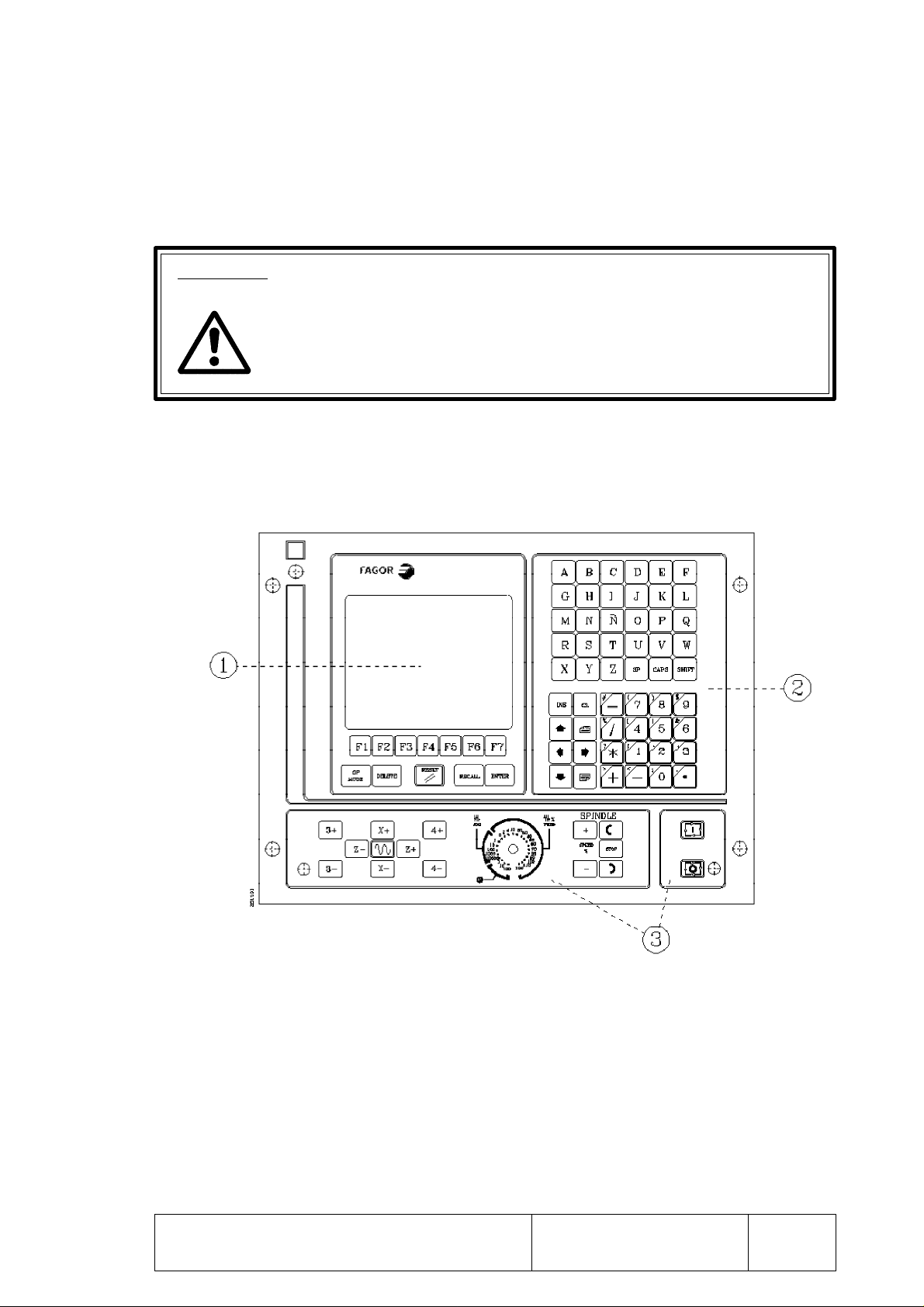
1.1 8025 CNC
The 8025 CNC is an enclosed compact module whose front view offers:
1. An 8" monochrome amber monitor or CRT screen used to display the required
system information.
2. A keyboard which permits communications with the CNC; being possible to
request information or change the CNC status by generating new instructions.
3. An operator panel containing the necessary keys to work in JOG mode as well
as the Cycle Start/Stop keys.
PageChapter: 1 Section:
CONFIGURATION OF THE CNC
8025 CNC
1
Page 25
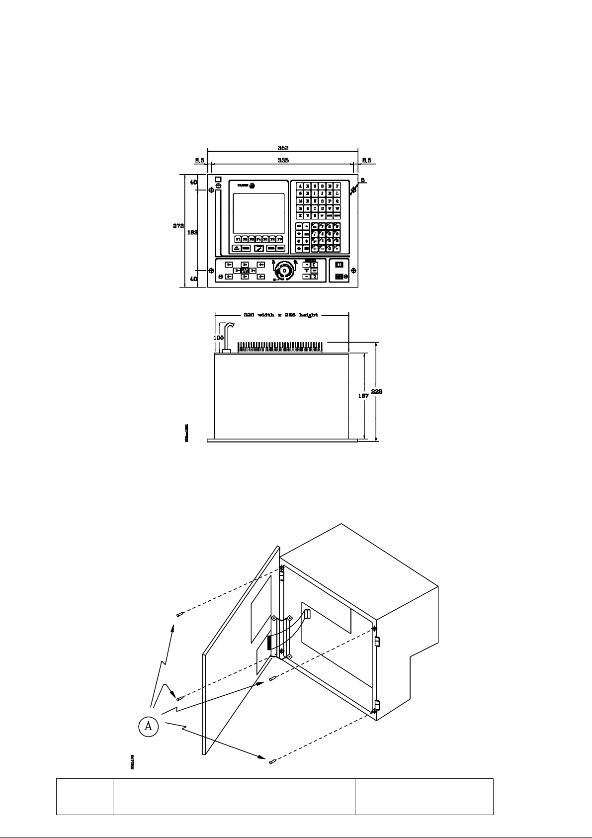
1.2 DIMENSIONS AND INSTALLATION OF THE 8025 CNC
This CNC, usually mounted on the machine pendant, has 4 mounting holes.
When installing it, leave enough room to swing the FRONT PANEL open in order
to allow future access to its interior.
To open it, undo the 4 allen-screws located next to the CNC mounting holes.
Page
2
CONFIGURATION OF THE CNC
Section:Chapter: 1
8025 CNC
Page 26
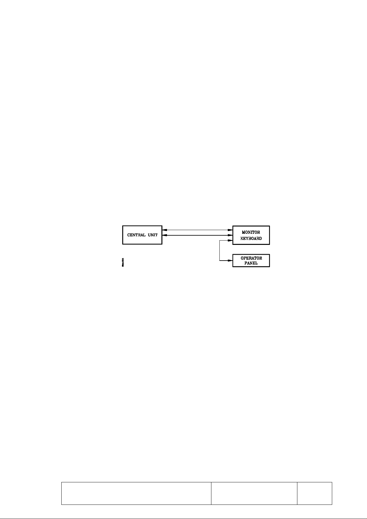
1.2 8030 CNC
This model CNC consists of 3 independent interconnected modules. These modules can be
mounted on different locations and they are:
- CENTRAL UNIT
- MONITOR/KEYBOARD
- OPERATOR PANEL
The OPERATOR PANEL module is connected to the MONITOR/KEYBOARD module
via a cable supplied with that module.
These two modules will be placed next to each other and must be connected with the
CENTRAL UNIT module which could be located somewhere else. The two cables used
to connect them together are also supplied with these modules. Their maximum length is 25
meters (82 feet) and they are referred to as:
- Video cable.
- Keyboard cable.
CONFIGURATION OF THE CNC
8030 CNC
PageChapter: 1 Section:
3
Page 27
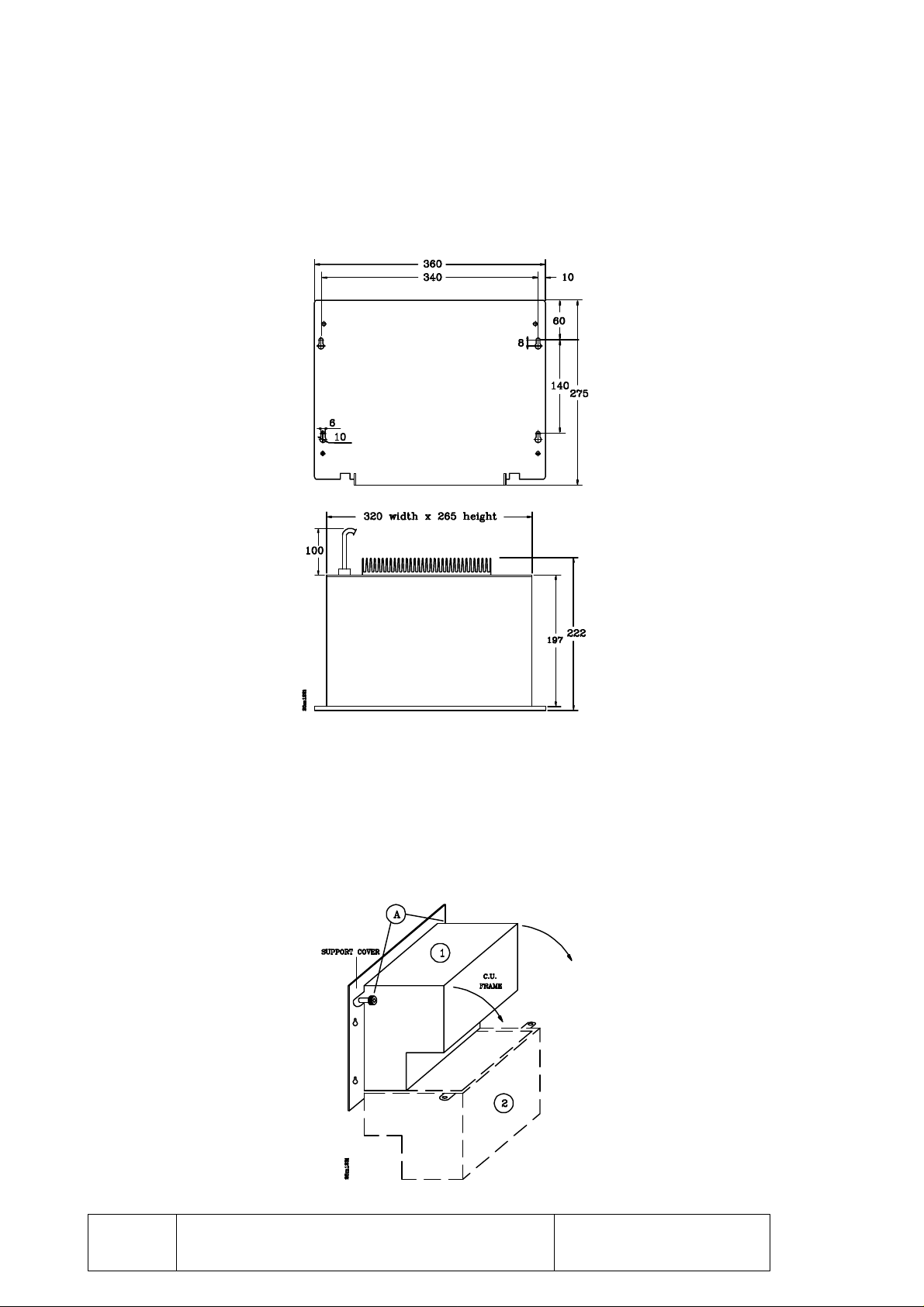
1.2.1 CENTRAL UNIT OF THE 8030 CNC
The CENTRAL UNIT is usually mounted in the electrical cabinet (machine enclosure) and
it is secured by means of the mounting holes located on the support cover.
When installing it, observe enough clearance to swing the CENTRAL UNIT open in case
of future inside manipulation.
To swing it open, once the support cover is secured on the machine enclosure, undo the two
knurled nuts on top and swing it open while holding the body of the CENTRAL UNIT.
Page
4
CONFIGURATION OF THE CNC
Section:Chapter: 1
CENTRAL UNIT
8030 CNC
Page 28
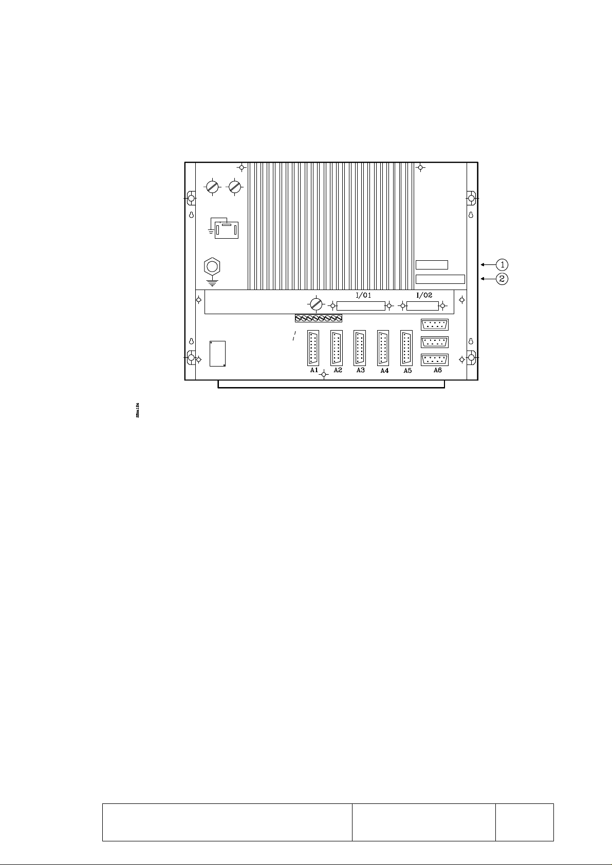
The CENTRAL UNIT has two connectors to connect it with the MONITOR/KEYBOARD
module by means of the video and keyboard signal cables.
1.- 15-pin SUB-D type female connector for for video signals.
2.- 25-pin SUB-D type female connector for keyboard signals.
CONFIGURATION OF THE CNC
CENTRAL UNIT
8030 CNC
PageChapter: 1 Section:
5
Page 29
1.2.1.1KEYBOARD CONNECTOR
It is a 25-pin SUB-D type female connector to connect the CENTRAL UNIT module to
the MONITOR/KEYBOARD module.
FAGOR AUTOMATION provides the cable required for this connection. It comes with
a 25-pin SUB-D type male connector at each end.
Both connectors have a latching system UNC4.40 by means of two screws.
PIN SIGNAL
1 GND
2 C9
3 C11
4 C13
5 C15
6 C1
7 C3
8 C5
9 C7
10 D1
11 D3
12 D5
13 D7
14 C8
15 C10
16 C12
17 C14
18 C0
19 C2
20 C4
21 C6
22 D0
23 D2
24 D4
25 D6
Metal hood Shield
The supplied cable has 25 wires (25 x 0.14mm²) with overall shield and acrylic cover. Its
maximum length must be 25 meters (82 feet).
Page
6
CONFIGURATION OF THE CNC
Section:Chapter: 1
CENTRAL UNIT
8030 CNC
Page 30
The cable shield is soldered to the metal hoods (housings) of both connectors and connected
to pin 1 at both the CENTRAL UNIT and the MONITOR/KEYBOARD connectors.
CONFIGURATION OF THE CNC
CENTRAL UNIT
8030 CNC
PageChapter: 1 Section:
7
Page 31

1.2.1.2VIDEO CONNECTOR
It is a 15-pin SUB-D type female connector used to interconnect the CENTRAL UNIT
module and the MONITOR/KEYBOARD module.
FAGOR AUTOMATION provides the cable required for this connection. It comes with
a 15-pin SUB-D type male connector at one end and a 15-pin SUB-D type female connector
at the other.
Both connectors have a latching system UNC4.40 by means of two screws.
PIN SIGNAL
1 GND
2 H
3 V
4 I
5 R
6 G
7 B
8 not connected
9 not connected
10 H
11 V
12 I
13 R
14 G
15 B
Metal hood shield
The supplied cable has 6 twisted-pairs of wires (6 x 2 x 0.34mm²) with overall shield and
acrylic cover. It has a specific impedance of 120 Ohm. Its maximum length must be 25
meters (82 feet).
The cable shield is soldered to the metal hoods (housings) of both connectors and connected
to pin 1 at both the CENTRAL UNIT and MONITOR/KEYBOARD connectors.
Page
8
CONFIGURATION OF THE CNC
Section:Chapter: 1
CENTRAL UNIT
8030 CNC
Page 32

1.2.2 MONITOR/KEYBOARD OF THE 8030 CNC
This module can be mounted on the machine pendant and it lets the operator get the
necessary information at the MONITOR as well as operate the CNC by means of its
KEYBOARD and OPERATOR PANEL.
This module has the connectors to connect it with the CENTRAL UNIT module.
1.2.2.1 DIMENSIONS OF THE MONITOR/KEYBOARD
CONFIGURATION OF THE CNC
MONITOR/KEYBOARD
8030 CNC
PageChapter: 1 Section:
9
Page 33

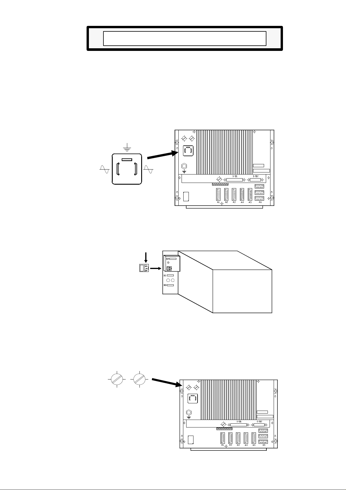
1.2.2.2 ELEMENTS OF THE MONITOR/KEYBOARD
X1 25-pin SUB-D type female connector for keyboard signals.
X2 15-pin SUB-D type male connector for video signals.
X3 15-pin SUB-D type female connector to connect the MONITOR/KEYBOARD
module to the OPERATOR PANEL module.
1.- A.C. power plug. Use the plug supplied with the unit to connect it to A.C. power and
ground.
2.- Ground terminal. Used for general machine ground connection. Metric 6 screw.
3.- Buzzer
Atention:
Do not manipulate inside this unit
Only personnel authorized by Fagor Automatin may manipulate inside
this module.
Do not manipulate the connectors with the unit connected to main AC
power
Before manipulating these connectors, make sure that the unit is not
connected to main AC power.
Page
10
CONFIGURATION OF THE CNC
Section:Chapter: 1
MONITOR/KEYBOARD
8030 CNC
Page 34

1.2.2.3 CONNECTORS AND MONITOR/KEYBOARD INTERFACE
Connectors X1, X2
They are described in the chapter corresponding to the CENTRAL UNIT.
Connector X3
It is a 15-pin SUB-D type female connector used to connect the MONITOR/
KEYBOARD with the OPERATOR PANEL.
FAGOR AUTOMATION supplies the cable required for this connection. It is a
250mm-long 15-wire ribbon cable.
To obtain a greater distance between the Monitor/Keyboard and the Operator Panel,
replace this cable with a round 15-conductor cable (15 x 0.14 mm²) with overall shield
and acrylic rubber cover. The length of this cable plus the length of the one used
between the Central Unit and the Keyboard (X1) must not exceed 25 meters (82 feet).
PIN SIGNAL
1
2 uC13
3 uC12
4 jC11
5 jC10
6 jC9
7 D7
8 D6
9 D5
10 D4
11 D3
12 D2
13 D1
14 D0
15 C14
CONFIGURATION OF THE CNC
MONITOR/KEYBOARD
8030 CNC
PageChapter: 1 Section:
11
Page 35

1.2.3 OPERATOR PANEL OF THE 8030 CNC
This module is connected to the MONITOR/KEYBOARD module via a ribbon cable and
it contains the JOG keys, Feedrate Override knob, Cycle Start and Stop keys, spindle keys
as well as an Emergency-stop push-button (mushroom) or an optional electronic handwheel.
X1 15-pin SUB-D type female connector to connect the MONITOR/KEYBOARD
module to the OPERATOR PANEL module.
It is described in the chapter corresponding to the MONITOR/KEYBOARD.
1.- Not being used at this time.
2.- Optional mounting location for the E-Stop button or Electronic handwheel.
Page
12
CONFIGURATION OF THE CNC
OPERATOR PANEL
Section:Chapter: 1
8030 CNC
Page 36

1.3 CONNECTORS AND 8025/8030 INTERFACE
A1 15-pin SUB-D type female connector to connect the X axis feedback system. It
accepts sine-wave signal.
A2 15-pin SUB-D type female connector to connect the feedback system for the
synchronized tool or the 4th axis. It accepts sine-wave signal.
A3 15-pin SUB-D type female connector to connect the Z axis feedback system. It
accepts sine-wave signal.
A4 15-pin SUB-D type female connector to connect the feedback system for the C
or 3rd axis. It accepts sine-wave signal.
A5 15-pin SUB-D type female connector to connect the spindle feedback system.
It does not accept sine-wave signal.
When using the spindle encoder and an electronic handwheel, the CNC will only
control up to 4 axes. This connector will then be used for the spindle encoder or
the electronic handwheel (the other device will be connected to A6).
A6 9-pin SUB-D type female connector to connect the spindle encoder or an electronic
handwheel and a touch probe. It does not accept sine-wave signal.
RS485 9-pin SUB-D type female connector to connect the RS485 serial line.
RS232C 9-pin SUB-D type female connector to connect the RS232C serial line.
CONFIGURATION OF THE CNC
CONNECTORS AND
INTERFACE
PageChapter: 1 Section:
13
Page 37

I/O1 37-pin SUB-D type female connector to interface with the electrical cabinet
offering 10 digital inputs, 16 digital outputs and 4 analog outputs for servo
drives (range: ±10 V.).
I/O2 25-pin SUB-D type female connector to interface with the electrical cabinet
offering 16 digital outputs and 2 analog outputs for servo drives (range:
±10V.).
1- Main AC fuse. It has two 3.15Amp./250V. fast fuses (F), one per AC line, to
protect the main AC input.
2- AC power connector To power the CNC. It must be connected to the power
transformer and to ground.
3- Ground terminal. It must be connected to the general machine ground point.
Metric 6.
4- Fuse. 3.15Amp./250V fast fuse (F) to protect the internal I/O circuitry of the CNC.
5- Lithium battery. Maintains the RAM data when the system's power disappears.
6- Adjustment potentiometers for the analog outputs. ONLY TO BE USED BY
THE TECHNICAL SERVICE DEPARTMENT.
7- 10 dip-switches. There are 2 under each feedback connector (A1 thru A5) and
they are utilized to set the CNC according to the type of feedback signal being
used.
8 CRT brightness adjustment potentiometer
9 Heat-sink.
Atention:
Do not manipulate the connectors with the unit connected to main AC power
Before manipulating these connectors, make sure that the unit is not
connected to main AC power.
Page
14
CONFIGURATION OF THE CNC
Section:Chapter: 1
CONNECTORS AND
INTERFACE
Page 38

1.3.1 CONNECTORS A1, A2, A3, A4
They are 15-pin SUB-D type female connectors used to connect the feedback signals.
* Connector A1 for X axis feedback signals.
* Connector A2 for the feedback signals from the live or synchronized tool.
When using a 4th axis, machine parameter "P614(1)" must be set to "1"
using feedback input A6 for the live or synchronized tool.
When not using a 4th axis, "P614(1)" must be set to "0" using this connector
for the live or synchronized tool.
Also, when using a live tool, machine parameter "P802" must be assigned
a value other than "0" and when using a synchronized tool, "P802" and
"P803" must be set to a value other than "0".
* Connector A3 for Z axis feedback signals.
* Connector A4 for the "C" or 3rd axis feedback signals.
In both cases, machine parameter "P612(1)" must be set to "1" indicating
that the machine has a 3rd axis.
When the 3rd axis is a "C" axis, "P613(5)" must be set to "1" indicating that
it is a "C" axis
The cable must have overall shield. The rest of the specifications depend on the feedback
system utilized and the cable length required.
It is highly recommended to run these cables as far as possible from the power cables
of the machine.
CONFIGURATION OF THE CNC
CONNECTORS
A1, A2, A3 & A4
PageChapter: 1 Section:
15
Page 39

PIN SIGNAL AND FUNCTION
1 A
2 A Differential square-wave feedback signals
3 B
4 B
5 Io Machine Reference Signals (marker pulses)
6 Io
7 Ac Sine-wave feedback signals
8 Bc
9 +5V. Power to feedback system.
10 Not connected.
11 0V. Power to feedback system.
12 Not connected.
13 -5V. Power to feedback system.
14 Not connected.
15 CHASSIS Shield
Atention:
When using square-wave rotary encoders, their signals must be TTL
compatible. Encoders with open collector outputs MUST NOT be used.
Do not manipulate the connectors with the unit connected to main AC
power
Before manipulating these connectors, make sure that the unit is not
connected to main AC power.
Page
16
CONFIGURATION OF THE CNC
Section:Chapter: 1
CONNECTORS
A1, A2, A3 & A4
Page 40

1.3.1.1 DIP-SWITCHES FOR CONNECTORS A1, A2, A3, A4
There are 2 dip-switches below each feedback input connector (A1 thru A4) to set the
CNC according to the type of feedback signal being used.
Switch 1 indicates whether the feedback signal is sine-wave or square-wave and switch
2 indicates whether the feedback signal is single- or double-ended (differential).
The possible types of feedback signals to be used at connectors A1 thru A4 are:
* Sine-wave (Ac, Bc, Io)
* Single-ended square-wave (A, B, Io)
* Double-ended (differential) square-wave (A, A, B, B, Io, Io)
To select the type of signal for each axis, use the switch combinations below:
Dip-switch SIGNAL AND FUNCTION
1 2
ON ON Single-ended sine-wave signal (Ac,Bc,Io)
ON OFF Double-ended sine-wave signal "Not allowed"
OFF ON Single-ended square-wave signal (A,B,Io)
OFF OFF Double-ended square-wave (A, A,B, B, Io, Io)
There is a label next to each dip-switch pair indicating the meaning of each switch.
CONFIGURATION OF THE CNC
CONNECTORS
A1, A2, A3 & A4
PageChapter: 1 Section:
17
Page 41

1.3.2 CONNECTOR A5
It is a 15-pin SUB-D type female connector for the spindle feedback signal.
It does not accept sine-wave signals.
The cable must have overall shield. The rest of the specifications depend on the feedback
system utilized and the cable length required.
It is highly recommended to run these cables as far as possible from the power cables
of the machine.
PIN SIGNAL AND FUNCTION
1 A
2 A Double-ended square-wave signal.
3 B
4 B
5 Io Machine Reference signals (marker pulse)
6 Io
7 Micro Io Spindle home switch signal input.
8 0V. Spindle home switch 0V input. (elec.cabinet)
Atention:
When using square-wave rotary encoders, their signals must be TTL
compatible. Encoders with open collector outputs MUST NOT be used.
Do not manipulate the connectors with the unit connected to main AC
power
9 +5V. Power to feedback system.
10 Not connected.
11 0V. Power to feedback system.
12 Not connected.
13 -5V. Power to feedback system.
14 Not connected.
15 CHASSIS Shield.
Before manipulating these connectors, make sure that the unit is not
connected to main AC power.
Page
18
CONFIGURATION OF THE CNC
Section:Chapter: 1
CONNECTOR A5
Page 42

1.3.2.1 DIP-SWITCHES FOR CONNECTOR A5
There are 2 dip-switches below this feedback input connector to set the CNC according
to the type of feedback signal being used.
Switch 1 indicates whether the feedback signal is sine-wave or square-wave and switch
2 indicates whether the feedback signal is single- or double-ended (differential).
The possible types of feedback signals to be used at connector A5 are:
* Single-ended square-wave (A, B, Io)
* Double-ended (differential) square-wave (A, A, B, B,Io, Io)
To select the type of signal for each axis, use the switch combinations below:
Dip-switch SIGNAL AND FUNCTION
1 2
ON ON Single-ended sine-wave signal "Not allowed"
ON OFF Double-ended sine-wave signal "Not allowed"
OFF ON Single-ended square-wave signal (A,B,Io)
OFF OFF Double-ended square-wave (A, A,B, B, Io, Io)
There is a label next to each dip-switch pair indicating the meaning of each switch.
CONFIGURATION OF THE CNC
CONNECTOR A5
PageChapter: 1 Section:
19
Page 43

1.3.3 CONNECTOR A6
It is a 9-pin SUB-D type female connector to connect the synchronized tool encoder
or the electronic handwheel and a touch probe. It does not take sine-wave signals.
The cable must have overall shield. The rest of the specifications depend on the feedback
system utilized and the cable length required.
It is highly recommended to run these cables as far as possible from the power cables
of the machine.
There are two probe inputs (5V and 24V) and the 0V of the external power supply
must be connected to the "probe 0V input" (pin 8).
The appendix of the manual includes information about these probe inputs as well as
recommended probe connection diagrams.
All cable shields must be connected to ground ONLY at the CNC end through the
connector leaving the other end of the cable not connected. The wires of a shielded
cable must not be unshielded (sticking out) for more than 75mm (about 3 inches).
PIN SIGNAL AND FUNCTION
Atention:
When using square-wave rotary encoders, their signals must be TTL
compatible. Encoders with open collector outputs MUST NOT be used.
When using a FAGOR 100P model handwheel, the axis selector signal must
be connected to pin 3.
1 A Square-wave signals
2 B Square-wave signals
3 Io Home marker pulse (Machine Reference)
4 +5V. Power to feedback system
5 0V. Power to feedback system
6 PROB 5 Probe input: 5 V. TTL
7 PROB 24 Probe input: 24 Vcc
8 0 PROB Probe input: 0 V.
9 CHASSIS Shield.
Page
20
Do not manipulate the connectors with the unit connected to main AC
power
Before manipulating these connectors, make sure that the unit is not
connected to main AC power.
Section:Chapter: 1
CONFIGURATION OF THE CNC
CONNECTOR A6
Page 44

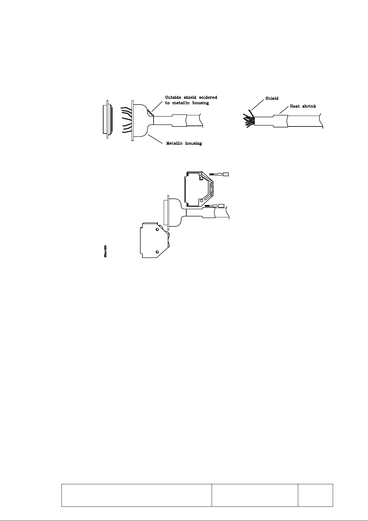
1.3.4 RS232C CONNECTOR
9-pin SUB-D type female connector to connect the RS 232 C serial port.
The cable shield must be soldered to pin 1 at the CNC end and to the metallic housing
at the peripheral end.
PIN SIGNAL FUNCTION
1 FG Shield
2 TxD Transmit Data
3 RxD Receive Data
4 RTS Request To Send
5 CTS Clear To Send
6 DSR Data Send Ready
7 GND Ground
8 —- Not connected
9 DTR Data Terminal Ready
SUGGESTIONS FOR THE RS232C INTERFACE
* Connect/disconnect peripheral.
The CNC must be powered off when connecting or disconnecting
any peripheral through this connector.
* Cable length. EIA RS232C standards specify that the capacitance of the cable
must not exceed 2500pF; therefore, since average cables have a capacitance between
130pF and 170pF per meter, the maximum length of the cable should not be greater
than 15m (49ft).
For greater distances, it is suggested to intercalate RS232C-to-RS422A signal
converters (and vice-versa). Contact the corresponding distributor.
Shielded cable with twisted-pair wires should be used to avoid communication
interference when using long cables.
Use shielded 7-conductor cable of 7*0.14mm² section.
* Transmission speed (baudrate). The baudrate normally used with peripherals is
9600 baud.
All unused wires should be grounded to avoid erroneous control and data signals.
* Ground connection. It is suggested to reference all control and data signals to the
same ground cable (pin 7 GND) thus, avoiding reference points at different voltages
especially in long cables.
CONFIGURATION OF THE CNC
RS232C CONNECTOR
PageChapter: 1 Section:
21
Page 45

RECOMMENDED CONNECTIONS FOR THE RS232C INTERFACE
* Complete connection
* Simplified connection
To be used when the peripheral or the computer meets one of the following
requirements:
- It does not have the RTS signal.
- It is connected via DNC.
- The receiver can receive data at the selected baudrate.
Nevertheless, it is suggested to refer to the technical manuals of the peripheral
equipment in case there should be any discrepancy.
Page
22
CONFIGURATION OF THE CNC
RS232C CONNECTOR
Section:Chapter: 1
Page 46

CONFIGURATION OF THE CNC
RS232C CONNECTOR
PageChapter: 1 Section:
23
Page 47

1.3.5 RS485 CONNECTOR
Impedance
107± 5% Ohm at 1 MHz.
---
Not connected
It is a 9-pin SUB-D type female connector to connect the RS485 serial line.
This serial line is used to integrate the CNC into the FAGOR LOCAL AREA
NETWORK (LAN) in order to communicate with other FAGOR CNCs and PLCs
(FAGOR PLC 64).
PIN SIGNAL FUNCTION
1 --2 --3 TxD Transmit Data
4 --5 --6 --7 --8 TxD Transmit Data
9
Not connected
Not connected
Not connected
Not connected
Not connected
Not connected
Atention:
Do not manipulate the connectors with the unit connected to main AC
power
Before manipulating these connectors, make sure that the unit is not
connected to main AC power.
For better immunity of the RS485 serial line against conducted electromagnetic
disturbances, it is recommended to solder the cable mesh to the metal hood
of the connector.
1.3.5.1 RECOMMENDED CABLE FOR THE RS485
TECHNICAL CHARACTERISTICS
CABLE “TWINAXIAL”
SPECIFICATIONS
Conductor
Insulator
Shields
Covering
Type:
Material:
Resistance:
Material: Teflon
Material
Type
Cover
Resistance
Material:
Outside diameter
Capacitance
02 AWG twisted 7x28
Copper (only one stained wire)
Max 11 L per every 305m. (1000 ft)
Stained copper
Braid 34 AWG. 8 ends / 16 carriers
Minimum 95%
Maximum 3L per every 305m. (1000 ft)
Teflon
Nominal 7mm. (0.257inches)
Maximum 53,1 pF/m (16.2 pF/ft)
Page
24
CONFIGURATION OF THE CNC
Section:Chapter: 1
RS485 CONNECTOR
Page 48

1.3.6 CONNECTOR I/O 1
It is a 37-pin SUB-D type female connector to interface with the electrical cabinet.
Pin SIGNAL AND FUNCTION
1 0V. Input from external power supply
2 T Strobe Output. The BCD outputs represent a tool code.
3 S Strobe Output. The BCD outputs represent a spindle speed code.
4 M Strobe Output. The BCD outputs represent an M code.
5 Emergency Output.
6 Threading ON Output.
Cycle ON
7 Z Enable Output.
8 Reset Output.
9 X Enable Output.
10 X home switch Input from machine reference switch.
11 3rd axis home switch Input from machine reference switch.
12 Z home switch Input from machine reference switch.
13 4th axis home switch Input from machine reference switch.
Emerg. Subroutine Activate the emergency subroutine.
14 Emergency Stop Input.
15 Feed Hold Input.
Transfer inhibit
M-done
16 Stop Input.
Emergency subrout. Activate the emergency subroutine.
17 Start Input
18 Block Skip Conditional Input
19 DRO Input. The CNC acts as a DRO
20 MST80 BCD coded output, weight: 80
21 MST40 BCD coded output, weight: 40
22 MST20 BCD coded output, weight: 20
23 MST10 BCD coded output, weight: 10
24 MST08 BCD coded output, weight: 8
25 MST04 BCD coded output, weight: 4
26 MST02 BCD coded output, weight: 2
27 MST01 BCD coded output, weight: 1
28 CHASSIS Connect all cable shields to this pin.
29 24V. Input from external power supply.
30 ±10V Analog output for X axis servo drive.
31 0V. Analog output for X axis servo drive.
32 ±10V Analog output for live tool.
33 0V. Analog output for live tool.
34 ±10V Analog output for Z axis servo drive.
35 0V. Analog output for Z axis servo drive.
36 ±10V Analog output for the spindle drive.
37 0V. Analog output for the spindle drive.
Atention:
The machine manufacturer must comply with the EN 60204-1 (IEC-204-1)
regulation regarding the protection against electrical shock derived from
defective input/output connection with the external power supply when this
connector is not connected before turning the power supply on.
Do not manipulate the connectors with the unit connected to main AC power
CONFIGURATION OF THE CNC
Before manipulating these connectors, make sure that the unit is not
connected to main AC power.
PageChapter: 1 Section:
CONNECTOR I/O1
25
Page 49

1.3.6.1 INPUTS OF CONNECTOR I/O 1
X AXIS HOME SWITCH Pin 10
This INPUT must be high (24V) as long as the machine reference switch for the
X axis is pressed.
"C" OR 3rd AXIS HOME SWITCH Pin 11
This INPUT must be high (24V) as long as the machine reference switch for the
"C" or 3rd axis is pressed.
Z AXIS HOME SWITCH Pin 12
This INPUT must be high (24V) as long as the machine reference switch for the
Z axis is pressed.
4th AXIS HOME SWITCH / Activate the emergency subroutine Pin 13
When the machine has a 4th axis, P614(1)=1, this input corresponds to the home
switch for this axis. This input must be high (24V) as long as the machine reference
switch for the 4th axis is pressed.
When the machine does not have a 4th axis, P614(1)=0, and an emergency
subroutine has been programmed, P716<>0, the CNC will activate such subroutine
every time this input is set low (0V).
EMERGENCY STOP Pin 14
This INPUT must be normally high (24V).
When set low (0V), the CNC deactivates the axis enables and analog voltages, it
interrupts the part program execution and it displays ERROR 64 on the CRT.
It does not imply an emergency output (pin 5 of this connector).
Page
26
CONFIGURATION OF THE CNC
Section:Chapter: 1
CONNECTOR I/O1
(inputs)
Page 50

FEED HOLD / TRANSFER INHIBIT / M-DONE Pin 15
This INPUT must be normally high (24V) and its meaning depends on the type
of block or function being executed at the time.
* If while moving the axes this signal (FEED-HOLD) is set low (0V), the CNC
maintains the spindle turning and stops the axes bringing their analog voltages
to 0V while maintaining their enables active.
When this input is brought back high (24V), the axes will resume their
movements.
* If while executing a motionless block this signal (TRANSFER INHIBIT) is set
low (0V), the CNC interrupts the program execution at the end of the block
currently in execution.
When this signal is brought back high, the CNC resumes program execution.
* The "M-DONE" signal is used when machine parameter "P602(7)" is set
to "1".
The CNC waits for the electrical cabinet to execute the requested
miscellaneous M function. In other words, it waits for the "M-done" input
to be set high (24V).
STOP/ Activate the emergency subroutine Pin 16
This INPUT must be normally high (24V) and its meaning depends on the the
system configuration.
* If the machine has a 4th axis, "P614(1)=1", and there is an emergency subroutine
(P716<>0), the CNC will activate the emergency subroutine whose number is
indicated by "P716" every time this input is set low.
* If the machine has neither a 4th axis, "P614(1)=0", nor an emergency subroutine
(P716=0), the CNC considers this input as (Cycle Stop) and acts as follows:
When this input is set low (0V), the CNC interrupts the program execution
just as if the key were pressed at the OPERATOR PANEL.
To resume program execution, it is necessary to bring this input back high
(24V) and press the key at the OPERATOR PANEL.
CONFIGURATION OF THE CNC
CONNECTOR I/O1
(inputs)
PageChapter: 1 Section:
27
Page 51

START Pin 17
This INPUT must be normally low (0V) and its meaning depends on the type of
operation selected.
While inactive, this input must be connected to 0V through a 10KOhm resistor.
When an up-flank (leading edge or low-to-high transition) of this signal (START)
is detected, the CNC considers that the external CYCLE START key is pressed
and it behaves as if the key were pressed at the OPERATOR PANEL.
However, to disable the key of the OPERATOR PANEL in order to only
use this input, set machine parameter P601(5) to "1".
BLOCK SKIP (Conditional input) Pin 18
Every time the CNC executes the miscellaneous function M01 (conditional stop),
it analyzes the status of this input. If high (24V), the CNC will interrupt the execution
of the program.
By the same token, every time the CNC must execute a conditional block, it will
analyze the status of this input and it will execute the block if this input is high
(24V).
DRO (DRO mode) Pin 19
If this input is set high (24V) while in the JOG mode, the CNC acts as a DRO.
Page
28
CONFIGURATION OF THE CNC
Section:Chapter: 1
CONNECTOR I/O1
(inputs)
Page 52

1.3.6.2 OUTPUTS OF CONNECTOR I/O 1
T Strobe Pin 2
The CNC sets this output high (24V) whenever it sends a tool code (T function)
via the BCD outputs (pins 20 thru 27).
S Strobe Pin 3
The CNC sets this output high (24V) whenever it sends a spindle speed code (S
function) via the BCD outputs (pins 20 thru 27).
M Strobe Pin 4
The CNC sets this output high (24V) whenever it sends an M function code via
the BCD outputs (pins 20 thru 27).
EMERGENCY Pin 5
The CNC activates this output whenever it detects an alarm condition or internal
emergency.
This output is normally high (24V) or low (0V) depending on the setting of machine
parameter P604(4).
THREADING ON / CYCLE ON Pin 6
This output is set normally low and its meaning depends on the setting of machine
parameter "P605(4)".
"P605(4)=0" THREADING ON.
The CNC activates this output, setting it high, when a threading operation is
being performed.
"P605(4)=1" CYCLE ON.
The CNC activated this output, setting it high, when executing a program block.
Z AXIS ENABLE Pin 7
The CNC sets this output high (24V) to enable the Z axis servo drive.
RESET Pin 8
The CNC sets this output high (24V) when resetting the CNC by means of the
[RESET] key.
The CNC keeps this signal active for 80 milliseconds.
CONFIGURATION OF THE CNC
CONNECTOR I/O1
(outputs)
PageChapter: 1 Section:
29
Page 53

X AXIS ENABLE Pin 9
The CNC sets this output high (24V) to enable the X axis servo drive.
MST80 Pin 20
MST40 Pin 21
MST20 Pin 22
MST10 Pin 23
MST08 Pin 24
MST04 Pin 25
MST02 Pin 26
MST01 Pin 27
The CNC uses these outputs to indicate to the electrical cabinet the M, S or T
function that has been selected.
This information is BCD coded and the significance (weight) of each output is
expressed by the corresponding mnemonic.
For example, to select the first spindle speed range, the CNC sends the M41 code
out to the electrical cabinet.
MST80 MST40 MST20 MST10 MST08 MST04 MST02 MST01
0 1 0 0 0 0 0 1
Together with these signals, the CNC will activate the "M Strobe", "T Strobe"
or "S Strobe" output to indicate the type of function being selected.
CHASSIS Pin 28
This pin must be used to connect all cable shields to it.
Analog voltage for X ±10V. Pin 30
Analog voltage for X 0V. Pin 31
These outputs provide the analog voltage for the X axis servo drive. The cable
used for this connection must be shielded.
Analog voltage for live tool ±10V. Pin 32
Analog voltage for live tool 0V. Pin 33
These outputs provide the analog voltage for the the live tool. The cable used for
this connection must be shielded.
Analog voltage for Z ±10V. Pin 34
Analog voltage for Z 0V. Pin 35
These outputs provide the analog voltage for the Z axis servo drive. The cable
used for this connection must be shielded.
Spindle analog voltage ±10V. Pin 36
Spindle analog voltage 0V. Pin 37
These outputs provide the analog voltage to govern the spindle when in open loop
(S) and when working as "C" axis. The cable used for this connection must be
shielded.
Page
30
CONFIGURATION OF THE CNC
Section:Chapter: 1
CONNECTOR I/O1
(outputs)
Page 54

1.3.7 CONNECTOR I/O 2
It is a 25-pin SUB-D type female connector to interface with the electrical cabinet.
PIN SIGNAL AND FUNCTION
1 0V. Input from external power supply.
2 0V. Input from external power supply.
3 Output M1 Value of bit 1 of the decoded M function table.
4 Output M2 Value of bit 2 of the decoded M function table.
5 Output M3 Value of bit 3 of the decoded M function table.
6 Output M4 Value of bit 4 of the decoded M function table.
7 Output M5 Value of bit 5 of the decoded M function table.
8 Output M6 Value of bit 6 of the decoded M function table.
9 Output M7 Value of bit 7 of the decoded M function table.
10 Output M8 Value of bit 8 of the decoded M function table.
11 Output M9 Value of bit 9 of the decoded M function table.
12 Output M10 Value of bit 10 of the decoded M function table.
13 Output M11 Value of bit 11 of the decoded M function table.
4th axis Enable
14 0V Analog voltage output for 4th axis servo drive.
15 ±10V. Analog voltage output for 4th axis servo drive.
16 CHASSIS Connect all cable shields to this pin.
17 0V Analog voltage output for 3rd axis servo drive.
18 ±10V. Analog voltage output for 3rd axis servo drive.
19 24V. Input from external power supply.
20 24V. Input from external power supply.
21 JOG Output. JOG mode is selected.
22 Output M15 Value of bit 15 of the decoded M function table.
Spindle lock
"C" axis Enable
23 Output M14 Value of bit 14 of the decoded M function table.
G00
24 Output M13 Value of bit 13 of the decoded M function table.
Turret Rotation
25 Output M12 Value of bit 12 of the decoded M function table.
3rd axis Enable
Atention:
The machine manufacturer must comply with the EN 60204-1 (IEC-204-
1) regulation regarding the protection against electrical shock derived from
defective input/output connection with the external power supply when this
connector is not connected before turning the power supply on.
Do not manipulate the connectors with the unit connected to main AC
power
CONFIGURATION OF THE CNC
Before manipulating these connectors, make sure that the unit is not
connected to main AC power.
PageChapter: 1 Section:
CONNECTOR I/O2
31
Page 55

1.3.7.1 OUTPUTS OF CONNECTOR I/O 2
"Decoded M" outputs Pins 3, 4, 5, 6, 7, 8, 9, 10, 11, 12, 13, 22, 23, 24, 25
These OUTPUTS provide the values indicated at the table corresponding to the
selected M function.
For example: If the table corresponding to function M41 has been set as follows:
M41 100100100100100 (outputs to be activated)
00100100100100100 (outputs to be deactivated)
Every time this M41 function is executed, the CNC will act as follows:
M01 M02 M03 M04 M05 M06 M07 M08 M09 M10 M11 M12 M13 M14 M15
Pin I/O2
at 24V
at 0V
Not
modified
3 4 5 6 7 8 9 10 11 12 13 25 24 23 22
x x x x x
x x x x x
x x x x x
Outputs M11 / 4th axis Enable Pin 13
This output provides the value of bit 11 of the decoded table corresponding to the
selected M function.
When the 4th axis is being used, "P614(1)=1", this output will be utilized as Enable
signal for this axis.
Therefore, When having a 4th axis, be careful not to set the bit of the decoded M
table which corresponds to this M11 output since the CNC will activate it in both
cases.
V axis analog voltage±10V. Pin 15
V axis analog voltage 0V. Pin 14
These outputs provide the analog voltage for the V axis servo drive. The cable
used for this connection must be shielded.
W axis analog voltage±10V. Pin 18
W axis analog voltage 0V. Pin 17
These outputs provide the analog voltage for the W axis servo drive. The cable
used for this connection must be shielded.
JOG Pin 21
The CNC sets this OUTPUT high (24V) whenever the JOG mode is selected.
Page
32
CONFIGURATION OF THE CNC
Section:Chapter: 1
CONNECTOR I/O2
Page 56

Outputs M15 / Spindle lock / "C" axis Enable Pin 22
This OUTPUT provides the value of bit 15 of the decoded M table corresponding
to the selected M function.
When the spindle is working in closed loop (M19), this output is used as the spindle
lock. That is, it will be set to "0" when the spindle has to move and it will return
to "1" when the spindle has reached its programmed position (within the in-position
or dead-band zone).
When the machine has a 3rd axis, "P612(1)=1" working as a "C" axis, "P613(5)=1",
this output will be used as "C" axis Enable.
Care must be taken, when having this option, not to use the bit of the decoded M
table corresponding to this output M15 since the CNC will activate it in both cases.
Outputs M14 / G00 Pin 23
This OUTPUT provides the value of bit 14 of the decoded M table corresponding
to the selected M function.
If machine parameter P604(3) is set to "1" so the CNC provides the status of the
G00 signal, this OUTPUT will be set high (24V) whenever the CNC is executing
a rapid positioning move (G00).
Care must be taken, when having this option, not to use the bit of the decoded M
table corresponding to this output M14 since the CNC will activate it in both cases.
CONFIGURATION OF THE CNC
CONNECTOR I/O2
PageChapter: 1 Section:
33
Page 57

Outputs M13 / Direction of turret rotation Pin 24
This OUTPUT provides the value of bit 13 of the decoded M table corresponding
to the selected M function.
If machine parameter "P609(6)=1", this OUTPUT is set high whenever the turret
turns in the positive direction.
For example, if a 12-tool turret is used and the current tool is number 2, the value
of this output will depend on the next tool being selected:
* When selecting tool 4 (positive direction 2, 3, 4), this output will be set high.
* When selecting tool 10 (negative direction: 2, 1, 12, 11, 10).
Care must be taken, when having one of these options, not to use the bit of the
decoded M table corresponding to this output M13 since the CNC will activate it
in both cases.
Outputs M12 / 3rd axis Enable Pin 25
This OUTPUT provides the value of bit 12 of the decoded M table corresponding
to the selected M function.
When the machine has a 3rd axis "P612(1)=1", this OUTPUT is used as the 3rd
axis Enable.
Care must be taken, when having this option, not to use the bit of the decoded M
table corresponding to this output M12 since the CNC will activate it in both cases.
Page
34
CONFIGURATION OF THE CNC
Section:Chapter: 1
CONNECTOR I/O2
Page 58

2. POWER AND MACHINE INTERFACE
Atention:
Power switch
This power switch must be mounted in such a way that it is esaily
accessed and at a distance between 0.7 meters (27.5 inches) and 1.7
meters (5.5 ft) off the floor.
Intall this unit in the proper place
It is recommended to install the CNC away from coolants, chemical
products, possible blows etc. which could damage it.
2.1 POWER INTERFACE
The rear of the 8025 CNC has a three-prong connector for AC and ground connection.
This connection must be done through an independent shielded 110VA transformer
with an AC output voltage between 100V and 240V +10% -15%.
The power outlet to connect the equipment must be near it and easily accessible.
In case of overload or overvoltage, it is recommended to wait for 3 minutes before
powering the unit back up in order to prevent any possible damage to the power
supply.
2.1.1 INTERNAL POWER SUPPLY
Inside the 8025 CNC there is a power supply providing the required voltages.
Besides the 2 outside AC power fuses (one per line), it has a 5 Amp. fuse inside to
protect it against overcurrent.
POWER AND MACHINE INTERFACE
POWER INTERFACE
PageChapter: 2 Section:
1
Page 59

2.2 MACHINE INTERFACE
2.2.1 GENERAL CONSIDERATIONS
The machine tool must have decoupled all those elements capable of generating
interference (relay coils, contactors, motors, etc.).
* D.C. Relay coils.
Diode type 1N4000.
* A.C. relay coils
RC connected as close as possible to the coils. Their approximate values should
be:
R 220 Ohms/1W
C 0,2 µF/600V
* A.C. motors.
RC connected between phases with values:
R 300 Ohms/6W
C 0,47µF/600V
Ground connection.
It is imperative to carry out a proper ground connection in order to achieve:
* Protection of anybody against electrical shocks caused by a malfunction.
* Protection of the electronic equipment against interference generated by the
proper machine or by other electronic equipment near by which could cause
erratic equipment behavior.
Therefore, it is crucial to install one or two ground points where the above
mentioned elements must be connected.
Use large section cables for this purpose in order to obtain low impedance and
efficiently avoid any interference. This way, all parts of the installation will have
the same voltage reference.
Even when a proper ground connection reduces the effects of electrical
interference (noise), the signal cables require additional protection.
This is generally achieved by using twisted-pair cables which are also covered
with anti-static shielding mesh-wire. This shield must be connected to a specific
point avoiding ground loops that could cause undesired effects. This connection
is usually done at one of the CNC's ground points.
Page
2
POWER AND MACHINE INTERFACE
Section:Chapter: 2
MACHINE INTERFACE
Page 60

Each element of the machine-tool/CNC interface must be connected to ground
via the established main points. These points will be conveniently set close to
the machine-tool and properly connected to the general ground (of the building).
When a second point is necessary, it is recommended to join both points with a
cable whose section is not smaller than 8 mm².
Verify that the impedance between the central point of each connector housing
and the main ground point is less than 1 Ohm.
Ground connection diagram
Chassis
Ground
Ground (for safety)
POWER AND MACHINE INTERFACE
MACHINE INTERFACE
PageChapter: 2 Section:
3
Page 61

2.2.2 DIGITAL OUTPUTS.
The CNC has several optocoupled digital outputs which may be used to activate
relays, deacons, etc.
These digital outputs, with galvanic isolation by optocouplers, can commutate D.C.
voltages supplied by the electrical cabinet of the machine.
The electrical characteristics of these outputs are:
Nominal voltage value +24 V D.C.
Maximum voltage value +30 V D.C.
Minimum voltage value +18 V D.C.
Output voltage Vcc.- 2V
Maximum output current 100 mA.
All outputs are protected by means of:
Galvanic isolation by optocouplers.
External 3A fuse for protection against output overload (greater than 125mA),
external power supply overvoltage (over 33V DC) and against reverse connection
of the external power supply.
2.2.3 DIGITAL INPUTS.
The digital inputs of the CNC are to used to "read" external devices.
All of them are galvanically isolated from the outside world by optocouplers.
The electrical characteristics of these inputs are:
Nominal voltage value +24 V DC
Maximum voltage value +30 V.
Minimum voltage value +18 V.
High threshold voltage (logic state 1) over +18V.
Low threshold voltage (logic state 0) under +5V.
Typical input consumption 5 mA.
Maximum consumption per input 7 mA.
All inputs are protected by means of:
Galvanic isolation by optocouplers.
Protection against reverse connection of the power supply up to -30V.
Atention:
The external 24V power supply used for the digital inputs and outputs
must be regulated.
Page
4
The 0V point of this power supply must be connected to the main ground
point of the electrical cabinet.
Section:Chapter: 2
POWER AND MACHINE INTERFACE
DIGITAL INPUTS/OUTPUTS
Page 62

2.2.4 ANALOG OUTPUTS.
The CNC has 6 analog outputs which could be used to command servo drives, spindle
drives and other devices.
The electrical characteristics of these outputs are:
Analog voltage range: ±10V.
Minimum impedance of the connected drive: 10 KOhm.
Maximum cable length without shield: 75 mm.
It is highly recommended to use the shielded cable connecting the shield to the
corresponding pin of the connector.
Atention:
It is recommended to adjust the servo drives so their maximum feedrate
(G00) is obtained at ±9.5 V.
2.2.5 FEEDBACK INPUTS
The feedback inputs are used to receive sine-wave, single-ended and double-ended
square-wave signals coming from linear or rotary transducers (encoders).
Connector A1 is used for the X axis feedback signals and it accepts sine-wave and
double-ended (differential) square-wave signals.
Connector A2 is used for the feedback signals from the 4th axis or the synchronized
tool and it accepts sine-wave and double-ended (differential) square-wave signals.
Connector A3 is used for the Z axis feedback signals and it accepts sine-wave and
double-ended (differential) square-wave signals.
Connector A4 is used for the feedback signals from the 3rd or "C" axis and it accepts
sine-wave and double-ended (differential) square-wave signals.
Connector A5 is used for the spindle feedback signals and it accepts double-ended
(differential) square-wave signals.
Connector A6 is used for the feedback signals from the probe and the electronic
handwheel or the synchronized tool. It accepts single-ended (not differential) squarewave signals.
The electrical characteristics of these inputs are:
Sine-wave signals Supply voltage ±5V.±5%
Maximum counting frequency 25KHz.
Square-wave signals Supply voltage ±5V.±5%
Maximum counting frequency 200KHz.
It is recommended to use shielded cables for their connection connecting the shield
to the corresponding pin of the connector.
PageChapter: 2 Section:
POWER AND MACHINE INTERFACE
ANALOG OUTPUTS
FEEDBACK INPUTS
5
Page 63

2.3 SET-UP
2.3.1 GENERAL CONSIDERATIONS
Inspect the whole electrical cabinet verifying the ground connections BEFORE
powering it up.
This ground connection must be done at a single machine point (Main Ground Point)
and all other ground points must be connected to this point.
Verify that the 24V external power supply used for the digital inputs and outputs is
REGULATED and that its 0V are connected to the Main Ground Point.
Verify the connection of the feedback system cables to the CNC.
DO NOT connect or disconnect these cables to/from the CNC when the CNC is on.
Look for short-circuits in all connectors (inputs, outputs, axes, feedback, etc.) BEFORE
supplying power to them.
2.3.2 PRECAUTIONS
It is recommended to reduce the axis travel installing the limit switches closer to
each other or detaching the motor from the axis until they are under control.
Verify that there is no power going from the servo drives to the motors.
Verify that the connectors for the digital inputs and outputs are disconnected.
Verify that the feedback dip-switches for each axis are set according to the type of
feedback signal being used.
Verify that the E-STOP button is pressed.
Page
6
POWER AND MACHINE INTERFACE
Section:Chapter: 2
SET-UP
Page 64

2.3.3 CONNECTION
Verify that the AC power is correct.
Being the CNC disconnected, power the electrical cabinet and verify that it responds
properly.
Verify that there is proper voltage between the pins corresponding to 0V and 24V
of the connectors for the digital inputs and outputs.
Apply 24V to each one of the terminals of the electrical cabinet being used that
correspond to the digital outputs of the CNC and verify their correct performance.
With the motors being decoupled from the axes, verify that the system consisting of
drive, motor and tacho is operating properly.
Connect the AC power to the CNC. The CRT will show the model number and the
available software (for example: CNC8025-TS).
After a self-test, the CNC will show the message: "GENERAL TEST PASSED". If
there is any problem, the CNC will display the corresponding error message.
POWER AND MACHINE INTERFACE
SET-UP
PageChapter: 2 Section:
7
Page 65

2.3.4 SYSTEM INPUT/OUTPUT TEST
This CNC offers a work mode which allows the possibility to activate or deactivate
each one of the logic inputs and outputs of the CNC.
To do this, press the following keystroke sequence:
[OP MODE]
[9] (SPECIAL MODES)
[0] (TEST)
After the self-test, the CNC will show at the bottom of the screen a series of options
which may be selected by means of the corresponding softkey.
By pressing the [IN/OUT] softkey, it will show the status of the logic inputs and it
will be possible to change the status of the logic outputs.
Logic inputs
INPUT PIN FUNCTION
A 17 (I/O 1) START
B 16 (I/O 1) STOP
C 15 (I/O 1) FEEDHOLD
D 14 (I/O 1) EMERGENCY STOP
E 13 (I/O 1) 4th axis home switch
F 12 (I/O 1) Z axis home switch
G 11 (I/O 1) 3rd axis home switch
H 10 (I/O 1) X axis home switch
I 19 (I/O 1) DRO mode
J 18 (I/O 1) Block skip (conditional stop)
K To be used only by the technical service
L To be used only by the technical service
M To be used only by the technical service
N To be used only by the technical service
The CNC will show at all times and dynamically the status of all these inputs.
To check a specific one, just actuate on the external push-button or switch
observing its behavior on the CRT.
The value of "1" on the screen indicates that the corresponding input is receiving
24V DC and a "0" indicates that it doesn't.
Page
8
POWER AND MACHINE INTERFACE
Section:Chapter: 2
SET-UP
Page 66

Logic outputs
ROW 1 ROW 2
OUTPUT PIN/FUNCTION PIN/FUNCTION
A (2 I/O 1) T Strobe (3 I/O 2) Output 1, decoded M
B (3 I/O 1) S Strobe (4 I/O 2) Output 2, decoded M
D (5 I/O 1) Emergency (6 I/O 2) Output 4, decoded M
E (6 I/O 1) Threading ON (7 I/O 2) Output 5, decoded M
F (7 I/O 1) Z Enable (8 I/O 2) Output 6, decoded M
G (8 I/O 1) Reset (9 I/O 2) Output 7, decoded M
H (9 I/O 1) X Enable (10 I/O 2) Output 8, decoded M
I (27 I/O 1) MST01 (11 I/O 2) Output 9, decoded M
J (26 I/O 1) MST02 (12 I/O 2) Output 10, decoded M
K (25 I/O 1) MST04 (13 I/O 2) Output 11, decoded M
L (24 I/O 1) MST08 (25 I/O 2) Output 12, decoded M
M (23 I/O 1) MST10 (24 I/O 2) Output 13, decoded M
N (22 I/O 1) MST20 (23 I/O 2) Output 14, decoded M
O (21 I/O 1) MST40 (22 I/O 2) Output 15, decoded M
P (20 I/O 1) MST80 (21 I/O 2) CNC in JOG mode
To check one of these outputs, select it with the cursor which may be moved by
means of the right and left arrow keys.
Once the desired output is selected, press "1" to activate it and "0" to deactivate
it. The CRT will show the status change.
It is possible to have several outputs active at the same time providing 24V at
their corresponding pins.
Once the INPUT/OUTPUT test is completed, disconnect the electrical cabinet and,
then, connect the input/output connectors as well as the feedback systems of the
axes to the CNC.
Then, connect the electrical cabinet and the CNC to AC power and activate the servo
drives.
POWER AND MACHINE INTERFACE
SET-UP
PageChapter: 2 Section:
9
Page 67

2.4 EMERGENCY INPUT/OUTPUT CONNECTION
The Emergency Input of the CNC is called EMERGENCY STOP (E-STOP) and
corresponds to pin 14 of connector I/O1. This input must normally have 24V DC.
The CNC processes this signal directly, therefore, whenever these 24V disappear, it
will issue EXTERNAL EMERGENCY ERROR (Error 64), it will deactivate the
axes enables and cancel the analog voltages for all the axes and the spindle.
It does NOT imply the emergency output (pin5).
The electrical cabinet interface must take into account all the external elements that
could cause this error.
For example, some of these elements may be:
* The E-Stop button has been pressed.
* An axis travel limit switch has been pressed.
* An axis servo drive is not ready.
On the other hand, whenever a CNC detects an internal emergency error, it will
activate the EMERGENCY OUTPUT at pin 5 of connector I/O1.
This output will be normally high or low depending on the setting of machine parameter
P605(8).
There are some of the internal causes that can activate this output:
* An excessive axis following error has occurred.
* An axis feedback error has occurred.
* There is erroneous data on the machine parameter table.
Page
10
POWER AND MACHINE INTERFACE
Section:Chapter: 2
EMERGENCY I/O
CONNECTION
Page 68

The recommended connection when P604(4)= 1 (output normally HIGH) is:
European Style:
USA Style:
POWER AND MACHINE INTERFACE
EMERGENCY I/O
CONNECTION
PageChapter: 2 Section:
11
Page 69

The recommended connection when P604(4)= 0 (output normally LOW) is:
European Style:
USA Style:
Page
12
POWER AND MACHINE INTERFACE
Section:Chapter: 2
EMERGENCY I/O
CONNECTION
Page 70

3. MACHINE PARAMETERS
Atention:
All unused machine parameters must be set to "0" to guarantee the proper
functioning of the 8025T CNC.
It is recommended to save the machine parameters of the CNC at a
peripheral device or computer in order to be able to recover them after
their accidental loss.
Please note that some of the machine parameters mentioned here are
described in greater detail in the chapter on "CONCEPTS" in this manual.
3.1 INTRODUCTION
On power-up, the CNC performs a system hardware test. When completed, it displays
the model name and the message: "GENERAL TEST PASSED" when successful
and the corresponding error message if otherwise.
In order for the machine-tool to be able to properly execute the programmed
instructions and recognize the interconnected elements, the CNC must "know" the
specific data for the machine such as feedrates, acceleration ramps, feedback devices,
etc.
This data is determined by the machine manufacturer and may be input via keyboard
or via the RS232C serial line by setting the machine parameters.
To lock or unlock access to machine parameters, decoded "M" function table and to
the leadscrew error compensation tables, proceed as follows:
* Press the [OP MODE] key.
* Press [6] to select the Editing mode.
* Press the softkey for [LOCK/UNLOCK]. The screen will show the word: "CODE:"
(password).
* Key in "PKAI1" and press [ENTER] to lock the access or key in "PKAI0" and
press [ENTER] to unlock the access.
When access to machine parameters is locked, only
communications via RS232C may be changed.
those regarding serial line
MACHINE PARAMETERS
INTRODUCTION
PageChapter: 3 Section:
1
Page 71

CAUTION when using a CNC with an integrated PLC (CNC+PLCI)
When using this access locking code, the machine parameters, the decoded "M"
function table and the leadscrew error compensation tables are stored in EEPROM
memory.
When using the access unlocking code, it recovers these previously stored tables
from the EEPROM memory.
Therefore, one must be careful and lock these tables before
unlocking them.
Otherwise, the factory set values or other prelocked values, may be restored overwriting
the ones the manufacturer entered but did not lock.
To enter the machine parameter values via the keyboard, press the following keystroke
sequence:
[OP MODE] (SPECIAL FUNCTIONS)
[9] (SPECIAL MODES)
[1] (MACHINE PARAMETERS)
Page
2
MACHINE PARAMETERS
Section:Chapter: 3
INTRODUCTION
Page 72

3.2 OPERATION WITH PARAMETER TABLES
Once the machine parameter table has been selected, the operator may view the
following or previous pages by means of the up and down arrow keys.
To view a particular parameter, key in the desired parameter number and press
[RECALL]. The CNC will display the page corresponding to that parameter.
To EDIT a parameter, key in the desired number, press [=] and key in the value to
be assigned to that parameter.
Depending on the type of machine parameter selected, it could be assigned one of
the following types of values:
* A number P111 = 30000
* A group of 8 bits P602 = 00001111
* A character P105 = Y
Once the value of the parameter has been keyed in, press [ENTER] so it is entered
on the table.
If when pressing [=], the parameter being edited disappears from the screen, it means
that the machine parameters are locked, therefore protected against modifications.
Once all the desired parameters have been set, either press [RESET] or power the
CNC off and back on so the CNC assumes the new values.
Every time a parameter bit is mentioned while describing the different machine
parameters, refer to this nomenclature:
P602 = 0 0 00 1 11 1
Bit 1
Bit 2
Bit 3
Bit 4
Bit 5
Bit 6
Bit 7
Bit 8
MACHINE PARAMETERS
OPERATION WITH
PARAMETER TABLES
PageChapter: 3 Section:
3
Page 73

3.3 GENERAL MACHINE PARAMETERS
P5 AC frequency:
Possible values: 50 Hz. and 60 Hz.
P99 Language
Determines the language used by the CNC to show texts and messages on the
screen.
0 = Spanish.
1 = German.
2 = English.
3 = French.
4 = Italian.
P13 Measuring units (mm/inches)
It determines the measuring units assumed by the CNC for machine parameters,
tool tables and work units at power-up and after emergency or RESET.
0 = Millimeters.
1 = Inches.
P11 X axis display in radius or diameter
0 = Radius
1 = Diameter
P600(1) Orientation of the axes
P600(1) = 0 P600(1) = 1
P801 Protected program
It indicates the number of the program to be protected against being read or
edited.
It is given by an integer between 0 and 9999. If "0" is assigned, the CNC will
interpret that no program is to be protected.
It is recommended to use this parameter to protect a program which contains the
subroutines which should remain unseen by the operator.
The protected program will not be listed on the program directory and when
requesting a subroutine defined in this program, the CNC will show the text:
“P????”.
Page
4
MACHINE PARAMETERS
Section:Chapter: 3
GENERAL
Page 74

3.3.1 PARAMETERS RELATED TO AXES CONFIGURATION
This CNC has 6 feedback inputs for the axes, A1 through A6, and the parameters
below make it possible to adapt the CNC to the type of machine available.
The possible axis combinations are:
Without Synchronized Tool With Synchronized Tool
A1 A2 A3 A4 A5 A6 A1 A2 A3 A4 A5 A6
X - Z - S Handwheel X Sync. Tool Z - S Handwheel
X - Z 3rd S Handwheel X Sync. Tool Z 3rd S Handwheel
X - Z C S Handwheel X Sync. Tool Z C S Handwheel
X 4th Z 3rd S Handwheel X 4th Z 3rd S
X 4th Z C S Handwheel X 4th Z C S
Handwheel
Sync. Tool
Handwheel
Sync. Tool
P612(1), P614(1) The machine has a 3rd, 4th axis
0 = The machine does not have a 3rd or a 4th axis.
1 = The machine has a 3rd or a 4th axis.
P613(5) The 3rd axis is the "C" axis
0 = It is not the C axis.
1 = It is the C axis.
P613(4), P615(4) the 3rd, 4th axis is called Y/W
0 = The 3rd, 4th axis is called Y.
1 = The 3rd, 4th axis is called W.
Obviously, when using both axes, one will be referred to as W and the other one
as Y. The W axis usually corresponds to the tail-stock.
P613(3), P615(3) The 3rd, 4th axis as a DRO axis
Indicates whether the CNC treats the corresponding axis as a normal axis or as
DRO axis.
0 = Normal axis.
1 = DRO axis.
MACHINE PARAMETERS
FOR AXES
CONFIGURATION
PageChapter: 3 Section:
5
Page 75

P613(1), P615(1) The 3rd, 4th axis is rotary
It indicates whether the axis is linear or rotary.
The position of a rotary axis is shown in degrees. Therefore, it is not affected by
the mm/inch unit change. It does not admit tool radius compensation or circular
interpolation.
0 = Linear axis.
1 = Rotary axis.
P613(2), P615(2) The 3rd, 4th axis is rotary ROLLOVER
This parameter is used when the axis is set as rotary, “P613(1)=1, P615(1)=1”
and the count is to roll over to 0° when reaching 360°.
0 = It is not ROLLOVER.
1 = It is ROLLOVER.
P613(6), P615(5) The 3rd, 4th axis is rotary rollover via shortest path
This parameter is used when the axis is set as rotary rollover and the programmed
movements are to be carried out via the shortest path.
0 = It is not positioned via the shortest path.
1 = It is positioned via the shortest path.
P616(8) Connector A6 shared by the handwheel and the synchronized tool
This parameter must be set to "1" when the machine has a 4th axis, synchronized
tool and electronic handwheel (all three).
A2 must be the feedback connector for the 4th axis, A6 must then be shared by
the synchronized tool and the electronic handwheel.
Pin 21 of connector I/O1 (output indicating JOG mode selected) may be used to
switch both feedbacks (synchronized tool and electronic handwheel) since the
electronic handwheel can only be used in JOG mode.
0 = Connector A6 is not shared.
1 = Connector A6 is shared.
Page
6
MACHINE PARAMETERS
Section:Chapter: 3
FOR AXES
CONFIGURATION
Page 76

3.3.2 I/O PARAMETERS
P604(4) Normal status of the Emergency output (pin 5 connector I/O 1)
It determines whether the emergency output is normally low or high.
0 = Normally low (0V). An emergency situation will set this output high
(24V).
1 = Normally high (24V). An emergency situation will set this output low
(0V).
P609(6) Pin 24 of connector I/O 2 indicates turret rotating direction
It determines whether pin 24 of connector I/O 2 is used to indicate the turrret
rotating direction or not.
0 = It is output 13 of the decoded M functions.
1 = It is the output indicating the turret rotating direction and output 13 of
the decoded M functions.
If this machine parameter is set to "1", this OUTPUT is set high (24V) whenever
the turret turns in the positive direction.
For example, if a 12-tool turret is used and the current tool is number 2, the
value of this output will depend on the next tool being selected:
* When selecting tool 4 (positive direction 2, 3, 4), this output will be set high.
* When selecting tool 10 (negative direction: 2, 1, 12, 11, 10).
Care must be taken, when having one of these options, not to use the bit of the
decoded M table corresponding to this output M13 since the CNC will activate
it in both cases.
P604(3) G00 mode indicating output at pin 23 of connector I/O 2
It determines whether pin 23 of connector I/O 2 is used to indicate the G00 mode
or not.
0 = It is output 14 of the decoded M functions.
1 = It is the G00 output and output 14 of the decoded M functions.
This output will stay active (24V) while the CNC is performing a G00 move
(rapid traverse).
It must be borne in mind that the CNC uses the same pin to indicate both concepts
(G00 and M14 output). Therefore, if it is to be used as an indicator for G00, this
bit must not be used when setting decoded M functions.
MACHINE PARAMETERS
I/O PARAMETERS
PageChapter: 3 Section:
7
Page 77

P605(4) Pin 6 of connector I/O 1 as THREADING-ON or CYCLE-ON indicator
0 = This output will be active (24V) when a THREADING cycle is being
executed.
1 = This output will be active (24V) when a program block is being executed
(CYCLE ON) is being executed or when a "BEGIN-START", "ENDSTART" type command is being executed.
P606(7) M function not output in BCD
When executing an M function which has been decoded at the M function table,
the CNC will activate and/or deactivate the corresponding outputs at connector
I/O 2.
This parameter determines whether or not besides activating the outputs set on
the table, the CNC also activates the BCD outputs: "MST01" thru "MST80" (pins
20 thru 27 of connector I/O 1) corresponding to that M function.
0 = The M function is also sent out in BCD.
1 = The M function is not sent out in BCD
P602(7) The CNC waits for a down flank (trailing edge) of the M-done signal.
It indicates whether it is necessary or not to wait for the down flank (change
from 24V to 0V) of the M-DONE signal (at pin 15 of connector I/O 1) in response
to an "S STROBE", "T STROBE" or "M STROBE" so the CNC resumes the
execution of such functions.
“P602(7)=0”
The CNC will send out to the electrical cabinet the BCD signals corresponding
to the M S or T code for a period of 200 milliseconds. Then, if the "M-DONE"
signal is low (0V), it will wait for it to be set high (24V) in order to consider
the M, S or T function done.
Page
8
MACHINE PARAMETERS
Section:Chapter: 3
I/O PARAMETERS
Page 78

“P602(7)=1”
50 milliseconds after having sent the M, S or T BCD signals out to the electrical
cabinet, it sends out the corresponding "Strobe" signal.
Then and if the "M-DONE" is high (24V), it waits for it to be set low (0V).
Once the "M-DONE" signal is set low, the CNC maintains the "Strobe" signal
active for another 100 milliseconds.
After deactivating the Strobe signal, the M, S or T BCD signals are kept active
for another 50 milliseconds.
After that time and if the "M-DONE" signal is low, the CNC will wait until
it becomes high so it can consider the auxiliary function M, S or T completed.
P603(4), P603(3), P603(2), P603(1), P608(1)
Cancellation of feedback alarm for connectors: A1, A2, A3, A4 and A5
The CNC will issue a feedback alarm for an axis when its corresponding feedback
signals are not received properly.
This parameter indicates whether this alarm is to be active or cancelled.
0 = Alarm active.
1 = Alarm cancelled.
This parameter must be set to "1" when the feedback system installed uses
only three square-wave signals (A, B, Io).
MACHINE PARAMETERS
I/O PARAMETERS
PageChapter: 3 Section:
9
Page 79

3.3.3 HANDWHEEL PARAMETERS
P609(1) The electronic handwheel is the FAGOR 100P
Indicates whether the electronic handwheel is or not a FAGOR handwheel model
100P (with axis selector button).
0 = It is not a FAGOR 100P.
1 = It is a FAGOR 100P.
P500 Counting direction of the handwheel
It sets the counting direction of the handwheel. If correct, leave it as is; otherwise,
assign the other value.
0 = NO and 1 = YES.
P602(1) Feedback units for the handwheel
It indicates whether the CNC considers the handwheel pulses to be in mm or in
inches.
0 = Millimeters.
1 = Inches.
P501 Feedback resolution of thehandwheel
It indicates the counting resolution of the handwheel.
Possible values with square-wave signals:
1 = Resolution of 0.001 mm, 0.0001 inch
2 = Resolution of 0.002 mm, 0.0002 inch
5 = Resolution of 0.005 mm, 0.0005 inch
10= Resolution of 0.010 mm, 0.0010 inch
P602(4) Multiplying factor for the feedback signals from the handwheel
It indicates the x2 or x4 multiplying factor to be applied to the feedback signals
supplied by the handwheel.
0 = x4.
1 = x2.
Example:
If the handwheel is set as follows:
P602(1) = 0 Millimeters
P501 = 1 0.001 mm resolution.
P602(4) = 0 x4
Page
10
The feedrate override switch is positioned at x100.
The selected axis will move 0.001mm x4 x100 = 0.4 mm per pulse received.
Section:Chapter: 3
MACHINE PARAMETERS
HANDWHEEL
PARAMETERS
Page 80

P619(7) Electronic handwheel managed by the PLC
It indicates whether the CNC assumes the handwheel positions of the manual
feedrate override switch or the PLCI outputs O44 and O45 or Marks M12, M13
of the PLC64 when jogging the axes with the handwheel.
0 = Assumes the Manual Feedrate Override Switch positions.
1= Assumes the setting of PLCI outputs O44 and O45 or Marks M12 and
M13 of the PLC64.
O44 O45
M12 M13
0 0 Assumes MFO switch settings
1 0 Equivalent to x1 of MFO switch
0 1 Equivalent to x10 of MFO switch
1 1 Equivalent to x100 of MFO switch
MACHINE PARAMETERS
HANDWHEEL
PARAMETERS
PageChapter: 3 Section:
11
Page 81

3.3.4 TOUCH PROBE PARAMETERS
P606(6) Pulse type of the touch probe
It indicates whether the probe functions of the CNC are active high (positive
pulse) or low (negative pulse) with the probe signal received at connector A6.
0 = Negative pulse (0V.).
1 = Positive pulse (5V. or 24V.).
P710 M function associated with the probing movement (G75)
It indicates the M function that is executed when a probing move is carried out
(G75).
It is defined by an integer between 0 and 99. If set to "0", no miscellaneous M
function will be executed.
The CNC executes the selected M function before starting the execution of G75.
The selected M function may be used, for example, to activate an infrared-based
probe.
P806 Probing feedrate in JOG mode
It indicates the probing feedrate used when calibrating and loading the tool length
by means of a touch probe in JOG mode.
Possible values: 1 thru 65.535 mm./minute (degrees/minute).
1 thru 25.800 tenths-of-inch/minute.
P902 Minimum X coordinate of the touch probe
P903 Maximum X coordinate of the touch probe
P904 Minimum Z coordinate of the touch probe
P905 Maximum Z coordinate of the touch probe
They determine the position the table-top probe occupies for tool calibration.
These coordinates are absolute and referred to Machine Reference Zero.
Possible values: ± 8388.607 millimeters.
± 330.2599 inches.
Page
12
MACHINE PARAMETERS
Section:Chapter: 3
PROBE PARAMETERS
Page 82

3.3.5 TOOL PARAMETERS
The section on "tools " in the chapter on "concepts" of this manual describes
how these parameters may be used.
P700 Number of tools
It is given by an integer between 0 and 32.
P730 Subroutine associated with the T function
It indicates the standard subroutine (not parametric) that will be executed when
the block in execution contains a T function. In other words, every time a tool
is selected in the part-program.
It is defined by an integer between 0 and 99. If set to "0", no subroutine will be
executed.
This way, it will be possible to define the corresponding standard subroutine to
select the desired tool.
Atention:
When associating a subroutine to the T function, the T function must be
the last programmed item on the block. Otherwise, the CNC will issue
the corresponding error code.
P617(2) The associated subroutine is executed before the T function
It determines whether the subroutine associated with the T function is executed
before or after the T function.
0 = It is executed after the T function.
1 = It is executed before the T function.
When the subroutine is executed before the T function, remember the following
considerations:
* The T function must be programmed alone in the block.
* If the T function is executed in the JOG or TEACH-IN modes, the CNC will
not execute the associated subroutine.
P604(5) The tool offset values are effective after executing M06
It indicates whether the tool offset is applied right after the T2.2 function is
executed or after M06 is executed.
0 = Tool offset effective after T2.2
1 = Tool offset effective after M06
For example: If every time a new tool is selected, the machine must make some
movements prior to the tool change; it is recommended to set this parameter to
"1" and program an M06 right after the tool change in the subroutine associated
to the T function.
MACHINE PARAMETERS
TOOL PARAMETERS
PageChapter: 3 Section:
13
Page 83

P609(3) The theoretical position corresponds to the tool tip or tool base
It indicates whether the CNC ignores the tool dimensions or not when displaying
the theoretical position. That is, whether the displayed position corresponds to
the tool tip or to the tool base.
0 = The displayed theoretical position value corresponds to the tool tip.
1 = The displayed theoretical position value corresponds to the tool base.
When setting this parameter to "0", the CNC will update the displayed position
after the tool change showing the new position corresponding to the tip of the
new tool.
This way, if an incremental move (G91) is programmed after a tool change, the
target position will be referred to the tip of the new tool.
On the other hand, when setting this parameter to "1", the CNC will not update
the displayed position and if an incremental move (G91) is programmed after a
tool change, the target position will be referred to the last programmed position.
Page
14
Section:Chapter: 3
MACHINE PARAMETERS TOOL PARAMETERS
Page 84

3.3.6 PARAMETERS RELATED TO THE EMERGENCY SUBROUTINE
P716 EMERGENCY subroutine
It indicates the number of the standard subroutine (not parametric) that will be
executed when activating the EMERGENCY SUBROUTINE input (pin 13 or16
of connector I/O1).
It is defined by an integer between 0 and 99. If set to "0", no emergency subroutine
will be executed.
P616(2) The Emergency subroutine executes M00
It indicates whether the CNC must execute an M00 after the Emergency subroutine
or not.
Function M00 interrupts program execution and is not output.
0 = M00 is executed.
1 = M00 is not executed.
P616(1) Coordinate assignment to arithmetic parameter in Emergency
subroutine
It indicates the coordinates to be assigned to an arithmetic parameter when
executing a "P0=X" type block in the emergency subroutine.
0 = It assigns the coordinates of the beginning point of the block interrupted
by the emergency.
1 = It assigns the coordinates of the point where the emergency input was
activated.
If at the beginning of the emergency subroutine we program the block: “P0=X
P2=Z”, and after performing all the emergency operations we program, inside
the emergency subroutine, a block with movement to point "XP0 ZP2", the tool
will return to the point of program interruption or to the beginning point of the
interrupted block.
MACHINE PARAMETERS
RELATED TO EMERGENCY
SUBROUTINE
PageChapter: 3 Section:
15
Page 85

3.3.7 MACHINE PARAMETERS FOR THE RS232C SERIAL LINE
P0 Transmission speed (baudrate)
It determines the transmission baudrate used in communications between the
CNC and the peripheral devices.
It is given by an integer (9600 maximum) and in baud units.
Typical values: 110
150
300
600
1,200
2,400
4,800
9,600
P1 Data bits per transmitted character
It determines the number of data bits used in each transmitted character.
Possible values:
7 = Only the 7 least significant bits (out of 8) are used. Assign this value
when transmitting standard ASCII characters.
8 = All 8 bits of the transmitted character are used. Assign this value when
transmitting special characters (ASCII code over 127).
P2 Parity
It determines the type of parity check used in the transmission.
Possible values:
0 = None.
1 = ODD parity.
2 = EVEN parity.
P3 Stop bits
It determines the number of stop bits used at the end of the transmitted word.
Possible values:
1 = 1 stop bit.
2 = 2 stop bits.
P605(5) DNC active
It indicates whether the CNC can work with the DNC protocol or not.
Page
16
0 = DNC function not available.
1 = DNC function available.
MACHINE PARAMETERS
Section:Chapter: 3
RS232C PARAMETERS
Page 86

P605(6) Type of communication, FAGOR Floppy Disk Unit or Cassette
P605(6) =1 Communication with a FAGOR Floppy Disk Unit. The CNC uses
the settings of machine parameters P0, P1, P2 and P3.
P605(6)=0 Communication with a FAGOR Cassette reader reader/recorder.
The CNC ignores the setting of parameters P0, P1, P2 and P3 and
it uses the following internal setting for the FAGOR Cassette
reader/recorder:
Baudrate = 13,714 Baud
Number of data bits = 7 bits
Parity = Even
Stop bits = 1
Atention:
In DNC communications as well as with peripherals, the CNC uses the
settings of machine parameters: P0, P1, P2 and P3.
P605(7) DNC protocol active on power-up
It indicates whether the DNC protocol is active on CNC power-up or not.
0 = DNC not active on power-up.
1 = DNC active on power-up.
P605(8) The CNC does not abort DNC communication (program debugging)
The CNC offers a safety system that aborts DNC communications whenever:
* More than 30 seconds elapse without receiving a character while in the reception
mode.
* More than 3 incorrect acknowledgments or non-acknowledgments occur in a
row while in transmission mode.
This parameter can be used in order to be able to debug a user communications
program without the CNC aborting the communication.
0 = The CNC aborts communications.
1 = The CNC does not abort communications (Debug mode).
P606(8) Status report by interruption
It indicates whether the "status report by interruption" is active or not while in
DNC mode.
0 = It is not active.
1 = It is active.
A more detailed explanation on this function can be found in the "DNC
COMMUNICATIONS PROTOCOL FOR THE 8025 CNC" manual.
PageChapter: 3 Section:
MACHINE PARAMETERS
RS232C PARAMETERS
17
Page 87

3.3.8 DISPLAY RELATED PARAMETERS
P6 Theoretical or Real display
It determines whether the CNC will display the real axis position or the theoretical
position.
0 (REAL) = The CNC displays the real position values (coordinates).
1 (THEO) = The CNC displays the theoretical position values (ignoring the
following error).
It is recommended to set this parameter to "0" during the adjustment of the machine
axes and then set it to "1" for normal operation.
P606(4,5) Axes orientation in graphic display
They determine the orientation of the axes in the graphic display so they match
the orientation of the machine axes.
P612(8), P614(8) 3rd, 4th axis display
They indicate whether the corresponding axis is or not displayed by the CRT.
0 = It is displayed.
1 = It is not displayed.
P611(7), P611(8) Monitor display color combination
They are used to choose the desired display color combination. The choices are:
P611(8) P611(7) Display color
0 0 Monochrome
0 1 Combination 1
1 0 Combination 2
Page
18
MACHINE PARAMETERS
DISPLAY PARAMETERS
Section:Chapter: 3
Page 88

3.3.9 JOG-MODE RELATED PARAMETERS
P12 Continuous or pulsating axis jog
It determines whether the selected axis moves (jogs) while the corresponding
jog key is pressed or it keeps moving until either the key or another JOG
key is pressed.
N = Continuous mode. The axis starts moving when its corresponding
JOG key is pressed and it stops when the key or any other
JOG key is pressed. When pressing the jog key for another axis,
this new axis will begin to move in the chosen direction until
or another JOG key is pressed.
Y = Pulsating mode. The axis will move while keeping the corresponding
JOG key pressed.
P600(2) JOG key assignment to the X and Z axes.
0 = The keys control the X axis and the keys control
the Z axis (horizontal lathe).
1 = The keys control the Z axis and the keys control
the X axis (vertical lathe).
P603(5) Possibility to execute the "S" function in JOG mode
It indicates whether it is possible or not to execute the "S" function while in JOG
mode.
0 = It is possible.
1 = It is not possible
P603(6) Possibility to execute the "T" function in JOG mode
It indicates whether it is possible or not to execute the "T" function while in JOG
mode.
0 = It is possible.
1 = It is not possible
P603(7) Possibility to execute the "M" function in JOG mode
It indicates whether it is possible or not to execute the "M" function while in
JOG mode.
0 = It is possible.
1 = It is not possible
MACHINE PARAMETERS
JOG-MODE
PARAMETERS
PageChapter: 3 Section:
19
Page 89

P619(8) Possibility to work at Constant Surface Speed while in JOG mode
It indicates whether it is possible or not to work at Constant Surface Speed while
in JOG mode.
0 = It is possible.
1 = It is not possible
P601(7) Recover initial conditions when returning to the standard work mode.
It determines whether or not the CNC must recover the initial conditions set by
machine parameters (spindle status, feedrates, etc.) every time the standard work
mode is accessed.
The standard work mode is accessed in the following cases:
* On CNC power-up, after pressing any key.
* When quitting the tool table.
* When quitting any of the auxiliary modes, general parameters, decoded M
functions, leadscrew compensation table, peripherals or the lock/unlock option.
0 = No, it does not recover the initial conditions.
1 = Yes, it does recover the initial conditions.
If this parameter is set to "1", the CNC will also generate an M30 function.
Page
20
MACHINE PARAMETERS
Section:Chapter: 3
JOG-MODE
PARAMETERS
Page 90

3.3.10 OPERATING-MODE RELATED PARAMETERS
P601(5) Inhibiting the START key.
It indicates whether the key from the front panel is ignored by the CNC
or not.
0 = It is not ignored. Not inhibited.
1 = It is ignored. Inhibited.
P619(6) Spindle inhibit via PLC.
To stop the spindle via PLC, it is possible to:
* Cancel (disable) the drive enable.
* Send the M05 code out to the CNC.
* Use the O43 signal of the PLCI or the M11 signal of the PLC64 to disable
or re-enable the Spindle.
This machine parameter, P619(6), indicates whether or not O43 (at the PLCI) or
M11 (at the PLC64) are used to enable or disable the spindle.
0 = They are not used.
1 = They are used.
When the CNC receives the spindle inhibiting signal, (O43 =1) or (M11=1), it
outputs an analog voltage of 0V; but it does not change the current spindle
conditions such as selected gear, rotating direction, etc.
When the spindle is re-enabled, (O43 =0) or (M11=0), the CNC outputs the
corresponding spindle analog voltage again.
P600(3) Maximum % value of the Feedrate Override Switch applied by the
CNC
It determines the maximum % value to be selected with The Feedrate Override
Switch.
0 = 120% of the programmed feedrate as indicated by the switch.
1 = limited to 100% of the programmed feedrate even when the switch
indicates 110% and 120%.
P4 Feedrate Override Switch active in rapid moves or not
It determines whether the Feedrate Override Switch is active during rapid moves
or not
N = The switch is ignored and the rapid moves are carried out at
100%.
Y = The CNC applies the % override indicated by the switch (between
0% and 100% even when indicating 110% and 120%).
MACHINE PARAMETERS
OPERATING-MODE
PARAMETERS
PageChapter: 3 Section:
21
Page 91

P607(8) G05 or G07 active on power-up
It determines whether the CNC assumes a G05 (round corner) or G07 (square
corner) on power-up.
0 = G07 (square corner)
1 = G05 (round corner)
P607(3) Vectored G00 (interpolated)
It determines whether the G00 moves are vectored (interpolated) or not.
0 = Not vectored G00 moves
1 = Vectored G00 moves.
P616(4) G59 as additive zero offset
It indicates whether function G59 is treated as normal zero offset or as an additive
zero offset.
0 = G59 as normal zero offset.
1 = G59 as additive zero offset.
When setting this parameter to "1", additive, every time a G54-G58 type function
is executed, the CNC applies on to each axis a zero offset equal to the sum of the
programmed offset value plus that of G59.
P609(5) Arithmetic parameters P150 through P254 as read-only
It indicates whether arithmetic parameters P150 through P254 are read/write or
read-only when the machine parameters are locked (code: PKAI1).
0 = Always read/write.
1 = When the machine parameters are locked, these arithmetic parameters
are read-only. When the machine parameters are not locked, these
arithmetic parameters are read/write.
P611(6) Function P1=0X uses the current work units (millimeters or inches)
It indicates whether or not the CNC uses the current work units when executing
a P1=0X type block.
0 = The current units are ignored. The axis position value with respect to
machine reference zero (home) is always considered to be in millimeters.
1 = The current units are used. The axis position value with respect to home
is taken in the currently active work units (millimeters or inches).
Page
22
MACHINE PARAMETERS
OPERATING-MODE
Section:Chapter: 3
PARAMETERS
Page 92

P621(4) Synchronization with independent axis
It indicates whether the independent axis (G65) is synchronized or not with the
next block.
0 = It is not synchronized.
1 = It is synchronized.
For example, When programming: N100 G65 X32
N110 G01 Z100
N120 G01 Z20
Depending on the setting of this machine parameter, the CNC will behave as
follows:
P621(4)=0 The CNC starts executing block N100 and, then, block N110. Once
block N110 is in position, the CNC continues executing the program
regardless of whether Block N100 has reached position or not.
P621(4)=1 The CNC starts executing block N100 and, then, block N110. Once
block N110 is in position, the CNC waits until block N100 reaches
position before going on to execute the rest of the program.
MACHINE PARAMETERS
OPERATING-MODE
PARAMETERS
PageChapter: 3 Section:
23
Page 93

4. MACHINE PARAMETERS FOR THE AXES
Please note that some of the machine parameters mentioned here are described
in greater detail in the chapter on "CONCEPTS" in this manual.
P100, P300, P200, P400 Sign of the analog output for X, Z, 3rd and 4th axes.
They determine the sign of the analog output. If correct, leave them as they are;
if not, change them.
Possible values: "N" and "Y".
IMPORTANT: When changing any of these parameters, also change the
corresponding "P101", "P301", "P201" or "P401" parameter in
order to prevent the axis from running away.
P101, P301, P201, P401 Counting direction of the X, Z, 3rd and 4th axis
feedback devices.
If correct, leave them as they are; if not, change them.
Possible values: "N" and "Y".
IMPORTANT: When changing any of these parameters, also change the
corresponding "P100", "P300", P200 or P400 parameter in order
to prevent the axis from running away.
P102, P302, P202, P402 Jogging direction for the X ,Z, 3rd and 4th axes.
They determine the jogging direction by means of the JOG keys of the operator
panel.
If correct, leave them as they are; if not, change them.
Possible values: "N" and "Y".
MACHINE PARAMETERS FOR THE AXES
PageChapter: 4 Section:
1
Page 94

4.1 PARAMETERS RELATED TO AXIS RESOLUTION
The section on "Axis resolution" in the chapter on "concepts" of this manual
describes how these parameters may be used.
P103, P303, P203, P403 X, Z, 3rd, 4th axis feedback resolution
They indicate the counting resolution for the axis.
Possible values for square-wave signals:
1 = Resolution of 0.001 mm, 0.0001 inch or 0.001°.
2 = Resolution of 0.002 mm, 0.0002 inch or 0.002°.
5 = Resolution of 0.005 mm, 0.0005 inch or 0.005°.
10 = Resolution of 0.010 mm, 0.0010 inch or 0.010°.
P619(1), P619(2), P619(3), P619(4) Counting resolution for X, Z, 3rd, 4th axis
with sine-wave feedback
When using sine-wave feedback signals, the CNC considers these parameters as
well as P103, P203, P303, and P403 to set the axis resolution.
Possible values for P103, P203, P303, and P403 with P619(1), P619(2), P619(3),
P619(4) = 0:
5 = Resolution of 0.001 mm, 0.0001 inch or 0.001°.
10 = Resolution of 0.002 mm, 0.0002 inch or 0.002°.
Possible values for P103, P203, P303, and P403 with P619(1), P619(2), P619(3),
P619(4), = 1:
1 = Resolution of 0.001 mm, 0.0001 inch or 0.001°.
2 = Resolution of 0.002 mm, 0.0002 inch or 0.002°.
5 = Resolution of 0.005 mm, 0.0005 inch or 0.005°.
10 = Resolution of 0.010 mm, 0.0010 inch or 0.010°.
P602(3), P602(2), P612(2), P614(2) X, Z, 3rd, 4th axis feedback units
They indicate the units of the feedback pulses for the corresponding axis.
0 = Millimeters or degrees
1 = Inches.
P106, P306, P206, P406 X, Z, 3rd, 4th axis feedback signal type
They indicate the type of feedback signals being used.
Y = Sine-wave feedback signals
N = Square-wave feedback signals
The CNC always applies a x5 multiplying factor to the sine-wave feedback signals.
Page
2
MACHINE PARAMETERS FOR THE AXES AXIS RESOLUTION
Section:Chapter: 4
Page 95

P602(6), P602(5), P612(5), P614(5) Multiplying factor for X, Z, 3rd, 4th
axis feedback signals
It indicates whether the CNC applies a x2 or x4 multiplying factor to the feedback
signals of the axes.
0 = It applies a x4 factor.
1 = it applies a x2 factor.
When using FAGOR linear transducers (scales), set the corresponding parameters
to "0".
Setting examples for the X axis:
Using square-wave linear transducers (scales):
Since the CNC applies either a x2 or x4 multiplying factor, a linear transducer
must be selected which has a signal period of twice or four times the desired
resolution.
Desired resolution
P602(3)=0 P602(3)=1
0.001 mm 0.0001 inch 1
0.002 mm 0.0002 inch 2
0.005 mm 0.0005 inch 5
0.010 mm 0.0010 inch 10
P103 P602(6)
x2 (=1) 0.002 mm
x4 (=0) 0.004 mm
x2 (=1) 0.004 mm
x4 (=0) 0.008 mm
x2 (=1) 0.010 mm
x4 (=0) 0.020 mm
x2 (=1) 0.020 mm
x4 (=0) 0.040 mm
Feedback
Signal period
FAGOR
Linear transducer
CX, CVX, MX
CX, CVX, MX
CT, CVT, MT, MVT, FT
CT, CVT, MT, MVT, FT
Using sine-wave linear transducers and P619(1)=1:
Besides the x2 or x4 selected by P602(6), the CNC applies an additional x5 factor
to the sinewave signals. Therefore, a transducer must be chosen which has a
feedback signal period 10 or 20 times the desired resolution.
If parameter P619(1)=1, it is possible to obtain resolution of 1, 2, 5 and 10 microns
or ten-thousandths of an inch.
Desired resolution
P602(3)=0 P602(3)=1
0.001 mm 0.0001 inch 1
0.002 mm 0.0002 inch 2
0.005 mm 0.0005 inch 5
0.010 mm 0.0010 inch 10
P103 P602(6)
x2 (=1) 0.010 mm
x4 (=0) 0.020 mm
x2 (=1) 0.020 mm
x4 (=0) 0.040 mm
x2 (=1) 0.050 mm
x4 (=0) 0.100 mm
x2 (=1) 0.100 mm
x4 (=0) 0.200 mm
Feedback
signal period
FAGOR
Linear transducer
CVS,MVS
CVS,MVS
FS
FS
MACHINE PARAMETERS FOR THE AXES AXIS RESOLUTION
PageChapter: 4 Section:
3
Page 96

Using sine-wave linear transducers and P619(1)=0:
Besides the x2 or x4 selected by P602(6), the CNC applies an additional x5 factor
to the sinewave signals. Therefore, a transducer must be chosen which has a
feedback signal period 10 or 20 times the desired resolution.
If parameter P619(1)=0, it is possible to obtain resolution of 1 and 2 microns or
ten-thousandths of an inch.
Desired resolution
P602(3)=0 P602(3)=1
0.001 mm 0.0001 inch 5
0.002 mm 0.0002 inch 10
P103 P602(6)
x2 (=1) 0.010 mm
x4 (=0) 0.020 mm
x2 (=1) 0.020 mm
x4 (=0) 0.040 mm
Feedback
signal period
FAGOR
Linear transducer
CVS,MVS
CVS,MVS
P604(2), P604(1), P612(3), P614(3) Binary encoder on X, Z, 3rd, 4th axis
It indicates whether the corresponding axis has a BINARY encoder (1024/2048
lines per turn) or not.
0 = It is a binary encoder.
1 = It is not a binary encoder.
P604(7), P604(6), P612(4), P614(4) Equivalence of the binary encoder used
for the X, Z, 3rd and 4th axes.
These parameters are used when having binary rotary encoders (of 1024 or 2048
lines /rev.) and the desired resolution requires either 1000, 1250, 2000 or 2500
counts/rev.
These parameters are to be set when using a binary encoder (1024 or 2048 pulses)
in place of one with 1000 or 1250 lines to obtain the desired resolution.
By setting this parameter, the CNC will adapt the encoder pulse-count as follows:
0 = It will treat the 1024-count binary encoder as a 1250-count and the 2048-
count binary encoder as a 2500-count encoder.
1 = It will treat the 1024-count binary encoder as a 1000-count and the 2048-
count binary encoder as a 2000-count encoder.
To calculate the axis resolution (P103, P203, P303, P403, P503) use the equivalent
number of pulses selected here (1000, 1250, 2000, 2500).
The usefulness of the binary encoders is obvious since the same encoder can be
utilized on two different types of leadscrews (for example 4-pitch and 5-pitch)
without having to stock two different encoder models.
Leadscrew pitch 1/4 inch/turn
Encoder = = = 1250 pulses/turn
Multiplying factor x Resolution x4 x 0.0001 inch/pulse
Leadscrew pitch 1/5 inch/turn
Encoder = = = 1000 pulses/turn
Multiplying factor x Resolution x2 x 0.0001 inch/pulse
Page
4
MACHINE PARAMETERS FOR THE AXES
FEEDBACK RESOLUTION
Section:Chapter: 4
Page 97

4.2 MACHINE PARAMETERS FOR AXIS ANALOG OUTPUTS
The section on "Adjustment of the axes" in the chapter on "concepts" of this
manual describes how these parameters may be used.
P117, P317, P217, P417 Minimum analog output for the X, Z, 3rd and 4th
axes
It is given by an integer value between 1 and 255.
Value of 1 = 2.5 mV.
Value of 10 = 25.0 mV. (10 x 2.5)
Value of 255 = 637.5 mV. (255 x 2.5)
P104, P304, P204, P404 Delay between Enable and Analog output for the
X, Z, 3rd and 4th axes
They determine whether a 400 msec. delay must be applied from the time the
Enable signal is activated to the instant the analog output is generated.
N = There is no delay between the two signals
Y = There is a 400 msec. delay between the two signals.
These parameters are to be used when there is no continuous control of the axes.
therefore the 400 msec. delay could be used to deactivate possible axis holding
devices (holding brake and so forth).
P118, P318, P218, P418 In-position zone for the X, Z, 3rd and 4th axes (dead
band)
The In-position zone is the positioning tolerance area around the programmed
position (coordinate) where the CNC considers an axis to be in position.
This area is expressed in microns regardless of the selected work units.
Value range: 0 thru 255 microns.
P105, P305, P205, P405 Continuous control of the X, Z, 3rd and 4th axes
They determine whether there is a continuous control of the axis or not once it
has reached position. That is: whether the Enable signal remains on or not when
the axis is in position.
N = The Enable signal disappears.
Y = The Enable signal is maintained (Continuous control).
The CNC keeps the axes in position when set as continuously controlled axis.
MACHINE PARAMETERS FOR THE AXES
AXIS ANALOG OUTPUT
PageChapter: 4 Section:
5
Page 98

4.3 MACHINE PARAMETERS FOR THE TRAVEL LIMITS OF THE AXES
The section on "Adjustment of the axes" in the chapter on "concepts" of this
manual describes how these parameters may be used.
P107, P307, P207, P407 Positive travel limit for the X, Z, 3rd and 4th axes
P108, P308, P208, P408 Negative travel limit for the X, Z, 3rd and 4th axes
They determine the positive and negative travel limits for the axes. Each one
must indicate the distance from Machine Reference Zero to each travel limit.
Value ranges: ± 8388.607 millimeters or degrees
± 330.2599 inches.
If both limits are set with the same value (for example "0"), the axis will not be
able to move.
For safety reasons, it is only possible to move the axes up to 100 microns from
the travel limits set by these parameters.
Page
6
MACHINE PARAMETERS FOR THE AXES
Section:Chapter: 4
AXIS TRAVEL LIMITS
Page 99

4.4 MACHINE PARAMETERS FOR THE LEADSCREWS
With this CNC, it is possible to compensate leadscrew errors due to the inaccuracy
along the ballscrew or to its backlash when changing the direction of the axis
movement.
4.4.1 LEADSCREW BACKLASH
P109, P309, P209, P409 Amount of leadscrew backlash for the X, Z, 3rd and
4th axes
When using linear scales, set this parameter to 0.
It is always expressed in microns regardless of the selected work units.
Value range: 0 thru 255 microns.
P620(1), P620(2), P620(3), Sign of the backlash for the X, Z, 3rd and 4th axes
Defines the sign of the backlash compensation value set in parameters P109,
P209, P309 and P409.
0 = Positive sign.
1 = Negative sign.
P113, P313, P213, P413 Additional analog pulse for X, Z, 3rd and 4th axis
backlash
Additional 40msec. analog pulse to recover the possible backlash of the leadscrew
when reversing movement direction.
It is given by an integer between 0 and 255.
Value of 0 = No additional pulse being applied.
Value of 1 = 2.5 mV.
Value of 10 = 25.0 mV. (10 x 2.5)
Value of 255 = 637.5 mV. (255 x 2.5)
Every time the movement is reversed, the CNC will apply to this axis its
corresponding analog voltage plus the additional pulse indicated by this parameter.
This additional pulse will last for 40 milliseconds.
When using rotary encoders, set this parameter to "0".
MACHINE PARAMETERS FOR THE AXES
LEADSCREW
PageChapter: 4 Section:
7
Page 100

4.4.2 LEADSCREW ERROR
There are 2 leadscrew compensation tables with 30 points each; one for the X axis
and another one for the Z axis.
For each point, it is required to define the position of the axis and the amount of
error at that point.
To access these tables, press the following keystroke sequence:
[OP MODE] Display of the various operating modes.
[9] Access to special modes.
[3] Access leadscrew error compensation tables.
The operator may view the following or previous pages by using the up and down
arrow keys.
To view a particular parameter, key in its number and press [RECALL]. The CNC
will show the page corresponding to that parameter.
To clear the table by setting all the parameters to 0, key in the following sequence:
[K] [J] [I] [ENTER].
Each parameter pair of this table represents:
Even parameter The position of the error point on the leadscrew. This position is
referred to Machine Reference Zero (home).
Value range: ±8388.607 millimeters
±330.2599 inches
Odd parameter The amount of leadscrew error at that point.
Value range: ±32.766 millimeters
±1.2900 inches
When defining the compensation points on the table, the following rules must be
observed:
* The even parameters are ordered according to their position along the axis. The
first pair of parameters (P0 or P60) must be set for the most negative (least positive)
point of the axis to be compensated.
* If all 30 points of the table are not required, set the unused ones to 0.
* For those sections outside the compensation area, the CNC will apply the
compensation defined for the nearest point.
* The Machine Reference Zero point (home) must be set with an error of 0.
* The maximum difference between the error values of two consecutive
compensation points must be within: ±0.127 mm (±0.0050 inches)
* The inclination of the error graph between two consecutive points cannot be
greater than 3%.
Page
8
MACHINE PARAMETERS FOR THE AXES LEADSCREW RELATED
Section:Chapter: 4
 Loading...