

Page 1

CNC
8065 TC
Operating manual
(Ref: 1201)
Page 2

MACHINE SAFETY
It is up to the machine manufacturer to make su re that the safety of the machine
is enabled in order to prevent personal injury and damage to the CNC or to the
products connected to it. On start-up and while validating CNC parameters, it
checks the status of t he following safety elements. If any of them is disabled, the
CNC shows a warning message.
• Feedback alarm for analog axes.
• Software limits for analog and sercos linear axes.
• Following error monitoring for analog and sercos axes (except the spindle)
both at the CNC and at the drives.
• Tendency test on analog axes.
FAGOR AUTOMATION shall no t be held responsible for any personal injuries or
physical damage cause d or suffered by the CNC resulting from any of the safety
elements being disabled.
HARDWARE EXPANSIONS
FAGOR AUTOMATION shall no t be held responsible for any personal injuries or
physical damage caused or suffered by the CNC resulting from any hardware
manipulation by personnel unauthorized by Fagor Automation.
If the CNC hardware is modified by personnel unauthor ized by Fagor Automation,
it will no longer be under warranty.
COMPUTER VIRUSES
FAGOR AUTOMATION guarantees that the software installed contains no
computer viruses. It is up to the user to keep the unit virus free in order to
guarantee its proper operation.
Computer viruses at the CNC may cause it to malfunction. An antivirus software
is highly recommended if the CNC is connected directly to another PC, it is part
of a computer network or floppy disks or other compute r media is used to transmit
data.
FAGOR AUTOMATION shall no t be held responsible for any personal injuries or
physical damage caused or suffered by the CNC due a computer virus in the
system.
If a computer vir us is found in the syste m, the unit will no longe r be under warranty.
All rights reserved. No part of this documentation may be transmitted,
transcribed, stored in a backup device or translated into another language
without Fagor Automation’s consent. Unauthorized copying or distributing of this
software is prohibited.
The information described in this manual may be changed due to technical
modifications. Fagor Automation reserves the right to make any changes to the
contents of this manual without prior notice.
All the trade marks a ppearing in the manual belong to the c orresponding owners.
The use of these marks by third parties for their own purpose could violate the
rights of the owners.
It is possible that CNC can execute more functions than those described in its
associated documentation; however, Fagor Automation does not guarantee the
validity of those applications. Therefore, except under the express permission
from Fagor Automation, any CNC application that is not described in the
documentation must be considered as "impossible". In any case, Fagor
Automation shall not be held responsible for any personal injuries or physical
damage caused or suffered by the CNC if it is used in any way other than as
explained in the related documentation.
The content of this manual and its validi ty for the product descr ibed here has been
verified. Even so, involuntary errors are possible, thus no absolute match is
guaranteed. Anyway, the contents of the manual is periodically checked making
and including the necessary corrections in a future edition. We appreciate your
suggestions for improvement.
The examples described in this manual are for learning purposes. Before using
them in industrial applications, they must be properly adapted making sure that
the safety regulations are fully met.
Page 3
Operating manual
INDEX
About the product ......................................................................................................................... 7
Declaration of conformity ............................................................................................................ 11
Version history ............................................................................................................................ 13
Safety conditions ........................................................................................................................ 15
Warranty terms ........................................................................................................................... 19
Material returning terms.............................................................................................................. 21
CNC maintenance ...................................................................................................................... 23
CHAPTER 1 GENERAL CONCEPTS
1.1 Accessing the conversational mode .............................................................................. 25
1.2 Keyboard........................................................................................................................ 26
CHAPTER 2 OPERATING IN JOG MODE
2.1 Introduction .................................................................................................................... 30
2.1.1 Standard screen of the conversational mode............................................................. 30
2.1.2 Auxiliary screen of the conversational mode.............................................................. 31
2.1.3 Cycle editing............................................................................................................... 33
2.1.4 Cycle simulation ......................................................................................................... 34
2.1.5 Cycle execution .......................................................................................................... 35
2.2 Operations with the axes. .............................................................................................. 36
2.2.1 Home search.............................................................................................................. 36
2.2.2 Jog ............................................................................................................................. 37
2.2.3 Jogging the axes with handwheels ............................................................................ 39
2.2.4 Moving an axis to a particular position (coordinate)................................................... 41
2.2.5 Coordinate preset....................................................................................................... 41
2.3 Spindle control ............................................................................................................... 42
2.4 Tool selection and tool change ...................................................................................... 43
2.5 Setting the feedrate and spindle speed. ........................................................................ 43
2.6 Setting and activating the zero offsets and the fixture offsets........................................ 44
2.7 Tool calibration............................................................................................................... 45
2.7.1 Manual calibration. Calibration without a probe ......................................................... 47
2.7.2 Semi-automatic calibration. Calibration with a probe ................................................. 50
2.7.3 Automatic calibration with a probe and a canned cycle (“plane” geometric configuration)
2.7.4 Automatic calibration with a probe and a canned cycle (“trihedron” geometric configu-
53
ration)55
CHAPTER 3 WORKING WITH OPERATIONS OR CYCLES
3.1 Canned cycles available in the editor. ........................................................................... 59
3.1.1 Configuring the cycle editor. ...................................................................................... 60
3.1.2 Teach-in mode. ......................................................................................................... 61
3.1.3 Selecting data, profiles and icons .............................................................................. 62
3.1.4 Definition of spindle conditions................................................................................... 63
3.1.5 Definition of machining conditions.............................................................................. 64
3.2 Positioning cycle. ...........................................................................................................65
3.3 Positioning cycle with M functions. ................................................................................ 66
3.4 Simple turning cycle....................................................................................................... 67
3.4.1 Basic operation .......................................................................................................... 69
3.5 Turning cycle with vertex rounding. ............................................................................... 71
3.5.1 Basic operation .......................................................................................................... 73
3.6 Simple facing cycle. ....................................................................................................... 75
3.6.1 Basic operation .......................................................................................................... 77
3.7 Facing cycle with vertex rounding. ................................................................................. 79
3.7.1 Basic operation .......................................................................................................... 81
3.8 Vertex chamfering cycle................................................................................................. 83
3.8.1 Basic operation .......................................................................................................... 86
3.9 "Chamfering between points" cycle. .............................................................................. 88
3.9.1 Basic operation .......................................................................................................... 91
3.10 Vertex chamfering cycle 2.............................................................................................. 93
3.10.1 Basic operation .......................................................................................................... 96
3.11 Vertex rounding cycle. ................................................................................................... 98
3.11.1 Basic operation ........................................................................................................ 101
CNC
8065 TC
(REF: 1201)
·3·
Page 4

Operating m anual
3.12 "Rounding between points" cycle................................................................................. 103
3.12.1 Basic operation ........................................................................................................ 106
3.13 Longitudinal threading cycle. ....................................................................................... 108
3.13.1 Basic operation ........................................................................................................ 111
3.14 Taper threading cycle. ................................................................................................. 112
3.14.1 Basic operation ........................................................................................................ 115
3.15 Face threading cycle.................................................................................................... 116
3.15.1 Basic operation ........................................................................................................ 119
3.16 Thread repair cycle. ..................................................................................................... 120
3.16.1 Basic operation ........................................................................................................ 123
3.17 Multi-entry threading cycle. .......................................................................................... 124
3.17.1 Basic operation ........................................................................................................ 127
3.18 Simple longitudinal grooving cycle. .............................................................................. 128
3.18.1 Basic operation ........................................................................................................ 131
3.18.2 Calibration of the grooving tool ................................................................................ 133
3.19 Simple face grooving cycle. ......................................................................................... 135
3.19.1 Basic operation ........................................................................................................ 138
3.19.2 Calibration of the grooving tool ................................................................................ 140
3.20 Inclined longitudinal grooving cycle. ............................................................................ 141
3.20.1 Basic operation ........................................................................................................ 144
3.21 Inclined face grooving cycle......................................................................................... 146
3.21.1 Basic operation ........................................................................................................ 149
3.22 Cut-off cycle. ................................................................................................................ 151
3.22.1 Basic operation ........................................................................................................ 153
3.23 Drilling cycle................................................................................................................. 154
3.23.1 Basic operation ........................................................................................................ 156
3.24 Tapping cycle...............................................................................................................157
3.24.1 Basic operation ........................................................................................................ 159
3.25 Multiple drilling cycle. ................................................................................................... 160
3.25.1 Basic operation ........................................................................................................ 163
3.26 Multiple tapping cycle. ................................................................................................. 164
3.26.1 Basic operation. ....................................................................................................... 166
3.27 Multiple slot milling cycle. ............................................................................................ 167
3.27.1 Basic operation ........................................................................................................ 170
3.28 Point-to-point turning cycle. ......................................................................................... 171
3.28.1 Basic operation ........................................................................................................ 175
3.28.2 Programming example............................................................................................. 176
3.29 Profile turning cycle. .................................................................................................... 177
3.29.1 Basic operation ........................................................................................................ 181
3.29.2 Programming examples ........................................................................................... 182
3.30 ZC plane profiling cycle. .............................................................................................. 188
3.30.1 Basic operation. ZC profile....................................................................................... 190
3.31 ZC/YZ rectangular pocket cycle................................................................................... 191
3.32 ZC/YZ circular pocket cycle. ........................................................................................ 193
3.33 2D ZC/YZ profile pocket cycle. .................................................................................... 195
3.34 XC plane profiling cycle. .............................................................................................. 197
3.34.1 Basic operation. XC profiles..................................................................................... 199
3.35 XC/XY rectangular pocket cycle. ................................................................................. 200
3.36 XC/XY circular pocket cycle......................................................................................... 202
3.37 2D XC/XY profile pocket cycle. .................................................................................... 204
CNC
8065 TC
(REF: 1201)
·4·
CHAPTER 4 STANDARD THREADS
4.1 Regular pitch metric thread — M (S.I.) ........................................................................ 208
4.2 Fine pitch metric thread — M (S.I.F.) ........................................................................... 209
4.3 Regular pitch Whitworth thread — BSW (W.) .............................................................. 210
4.4 Fin pitch Whitworth thread — BSF .............................................................................. 211
4.5 Regular pitch Unified American thread — UNC (NC, USS) ......................................... 212
4.6 Fine pitch Unified American thread — UNF (NF, SAE) ............................................... 213
4.7 Whitworth gas thread — BSP ...................................................................................... 214
CHAPTER 5 SAVING PROGRAMS
5.1 List of saved programs ................................................................................................ 216
5.2 Edit a new part-program .............................................................................................. 217
5.3 Delete a new part program .......................................................................................... 217
5.4 Save a cycle ................................................................................................................ 217
CHAPTER 6 EXECUTION AND SIMULATION
6.1 Execute a part-program ............................................................................................... 220
6.1.1 Execute a portion of a part-program ........................................................................ 220
6.1.2 Graphics screen in execution................................................................................... 221
Page 5

Operating manual
6.2 Simulating a part-program ........................................................................................... 222
6.2.1 Simulate a portion of a part-program ....................................................................... 222
6.2.2 Graphics screen in simulation. ................................................................................. 223
6.3 Simulating or executing an operation that has been saved ......................................... 224
6.3.1 Simulating a cycle .................................................................................................... 224
6.3.2 Cycle execution ........................................................................................................ 225
CNC
8065 TC
(REF: 1201)
·5·
Page 6

Page 7
Operating manual
ABOUT THE PRODUCT
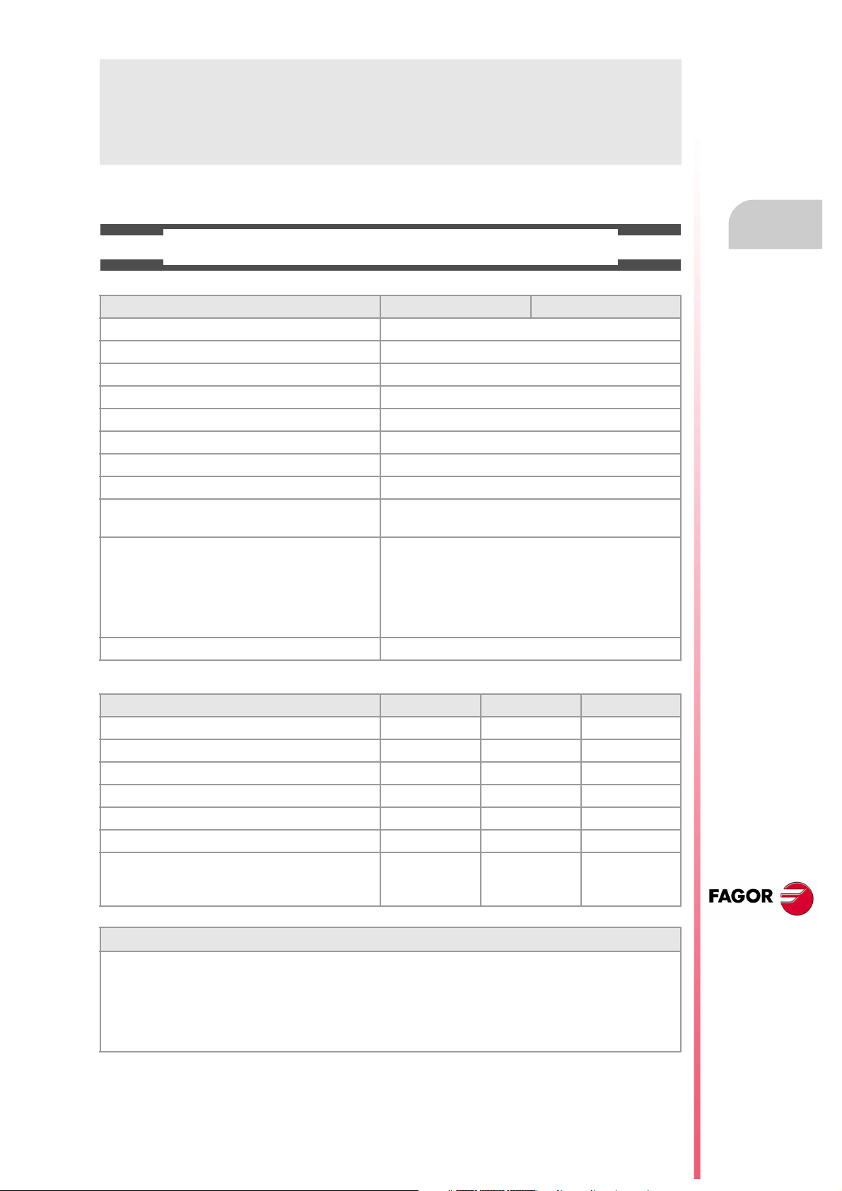
BASIC CHARACTERISTICS.
Basic characteristics. ·M· ·T·
PC-based system. Open system
Operating system. Windows XP
Number of axes. 3 to 28
Number of spindles. 1 to 4
Number of tool magazines. 1 to 4
Number of execution channels. 1 to 4
Number of handwheels. 1 to 12
Type of servo system. Analog / Digital Sercos / Digital Mechatrolink
Communications. RS485 / RS422 / RS232
Ethernet
Integrated PLC.
PLC execution time.
Digital inputs / Digital outputs.
Marks / Registers.
Timers / Counters.
Symbols.
Block processing time. < 1 ms
< 1ms/K
1024 / 1024
8192 / 1024
512 / 256
Unlimited
Remote modules. RIOW RIO5 RIO70
Communication with the remote modules. CANopen CANopen CANfagor
Digital inputs per module. 8 16 or 32 16
Digital outputs per module. 8 24 or 48 16
Analog inputs per module. 4 4 8
Analog outputs per module. 4 4 4
Inputs for PT100 temperature sensors. 2 2 - - -
Feedback inputs. - - - - - - 4
Differential TTL
Sinusoidal 1 Vpp
Customizing.
PC-based open system, fully customizable.
INI configuration files.
FGUIM visual configuration tool.
Visual Basic®, Visual C++®, etc.
Internal databases in Microsoft® Access.
OPC compatible interface
CNC
8065 TC
(REF: 1201)
·7·
Page 8
Operating m anual
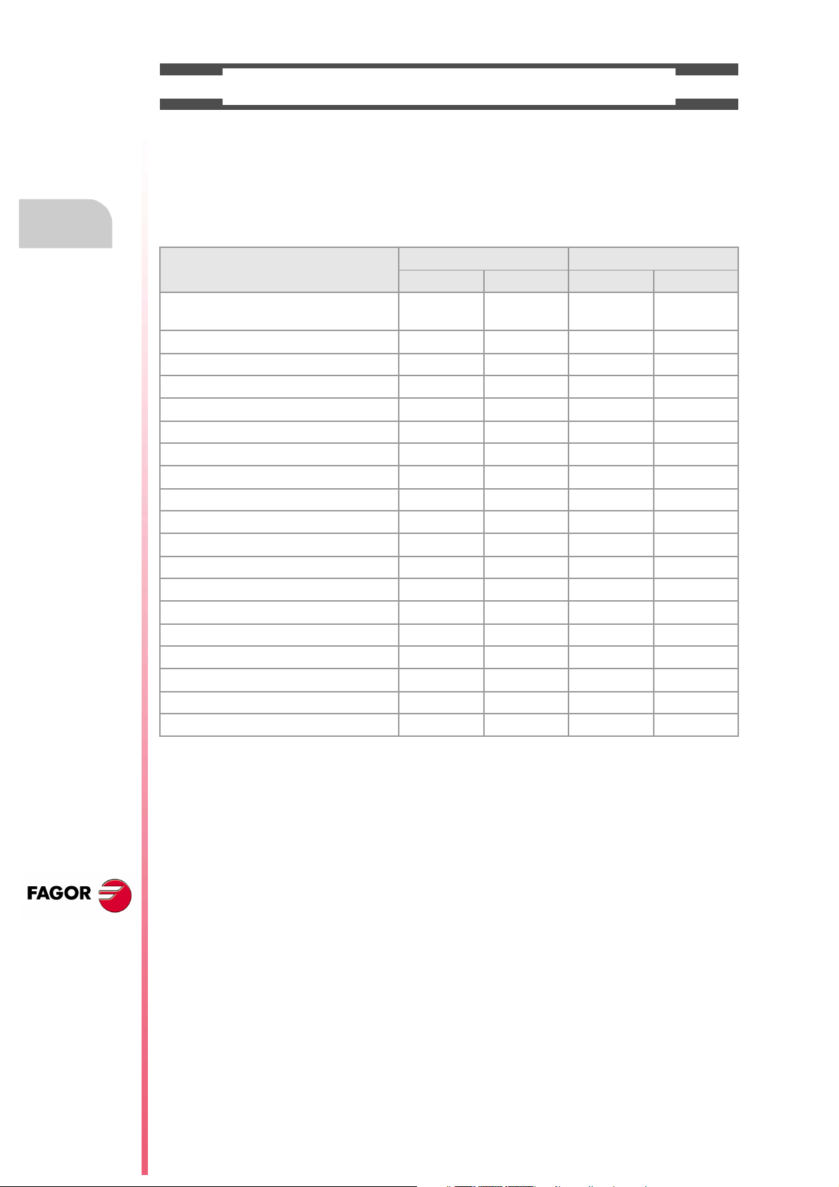
SOFTWARE OPTIONS.
Bear in mind that some of the features described in this manual depend on the software options that are
installed. The information of the following table is informative only; when purchasing the software options,
only the information provided in the ordering handbook is valid.
Software options (·M· model).
8065 M 8065 M Power
Basic Pack 1 Basic Pack 1
Open system.
Access to the administrator mode.
Number of execution channels 1 1 1 1 to 4
Number of axes 3 to 6 5 to 8 5 to 12 8 to 28
Number of spindles 1 1 to 2 1 to 4 1 to 4
Number of tool magazines 1 1 1 to 2 1 to 4
Limited to 4 interpolated axes Option Option Option Option
IEC 61131 language - - - Option Option Option
HD graphics Option Option Standard Standard
Conversational IIP Option Option Option Option
Dual-purpose machines (M-T) - - - - - - Option Standard
"C" axis Standard Standard Standard Standard
Dynamic RTCP - - - Option Option Standard
HSSA machining system. Standard Standard Standard Standard
Probing canned cycles Option Standard Standard Standard
Tandem axes - - - Option Standard Standard
Synchronism and cams - - - - - - Option Standard
Tangential control - - - Standard Standard Standard
Volumetric compensation (up to 10 m³). - - - - - - Option Option
Volumetric compensation (more than 10 m³). - - - - - - Option Option
- - - - - - Option Option
CNC
8065 TC
(REF: 1201)
·8·
Page 9
Operating manual
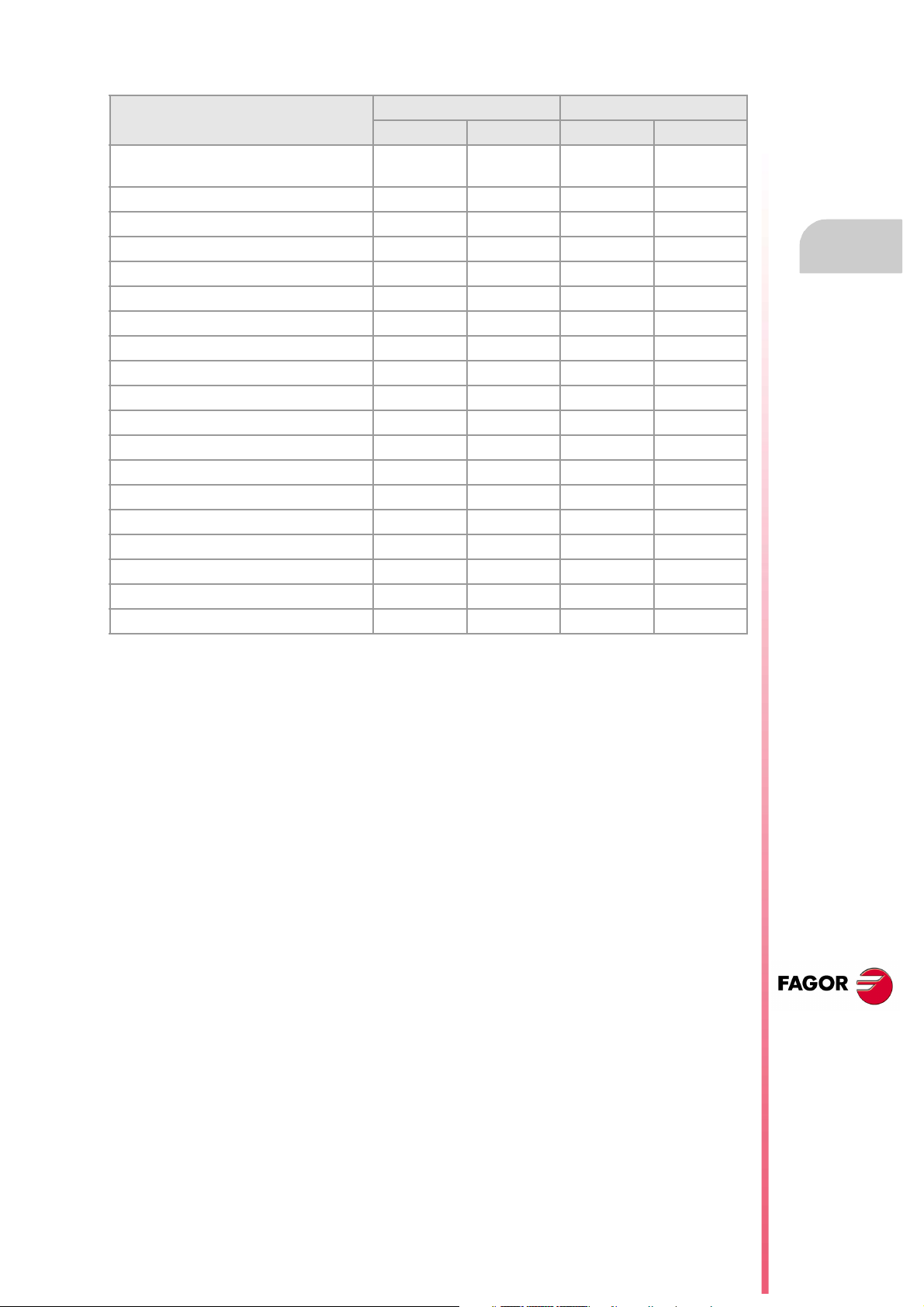
Software options (·T· model).
8065 T 8065 T Power
Basic Pack 1 Basic Pack 1
Open system.
Access to the administrator mode.
Number of execution channels 1 1 to 2 1 to 2 1 to 4
Number of axes 3 to 5 5 to 7 5 to 12 8 to 28
Number of spindles 2 2 3 to 4 3 to 4
Number of tool magazines 1 1 to 2 1 to 2 1 to 4
Limited to 4 interpolated axes Option Option Option Option
IEC 61131 language - - - Option Option Option
HD graphics Option Option Standard Standard
Conversational IIP Option Option Option Option
Dual-purpose machines (T-M) - - - - - - Option Standard
"C" axis Option Standard Standard Standard
Dynamic RTCP - - - - - - Option Standard
HSSA machining system. Option Standard Standard Standard
Probing canned cycles Option Standard Standard Standard
Tandem axes - - - Option Standard Standard
Synchronism and cams - - - Option Option Standard
Tangential control - - - - - - Option Standard
Volumetric compensation (up to 10 m³). - - - - - - Option Option
Volumetric compensation (more than 10 m³). - - - - - - Option Option
- - - - - - Option Option
CNC
8065 TC
(REF: 1201)
·9·
Page 10

Page 11
Operating manual
DECLARATION OF CONFORMITY
The manufacturer:
Fagor Automation S. Coop.
Barrio de San Andrés Nº 19, C.P.20500, Mondragón -Guipúzcoa- (Spain).
Declares:
The manufacturer declares under their exclusive responsibility the conformity of the product:
8065 CNC
Consisting of the following modules and accessories:
8065-M-ICU
8065-T-ICU
MONITOR-LCD-10, MONITOR-LCD-15
HORIZONTAL-KEYB, VERTICAL-KEYB, OP-PANEL
BATTERY
Remote Modules RIOW, RIO5, RIO70
Note.Some additional characters may follow the model references indicated above. They all comply with the
directives listed here. However, compliance may be verified on the label of the unit itself.
Referred to by this declaration with following directives:
Low-voltage regulations.
EN 60204-1: 2006 Electrical equipment on machines — Part1. General requirements.
Regulation on electromagnetic compatibility.
EN 61131-2: 2007 PLC — Part 2. Equipment requirements and tests.
According to the European Community Directives 2006/95/EC on Low Voltage and 2004/108/EC
on Electromagnetic Compatibility and their updates.
In Mondragón, October 1st 2011.
CNC
8065 TC
(REF: 1201)
·11·
Page 12

Page 13
Operating manual
VERSION HISTORY
Here is a list of the features added to each manual reference.
Ref. 1103
Software V04.20
First version.
Ref. 1201
Software V04.22
Canned cycles. Point-to-point turning cycle. The table to define the points of the profile admits 25 points.
Canned cycles. Point-to-point turning cycle. New icon to delete all the points of the table.
Canned cycles. Multiple tapping cycle. The cycle allows programming the dwell at the bottom.
Canned cycles. Multiple slot milling cycle. The cycle allows defining several penetration passes.
Canned cycles. By default, the cycles assume for Xf the value set for Xi.
• Simple turning cycle.
• Turning cycle with vertex rounding.
• Simple facing cycle.
• Facing cycle with vertex rounding.
• "Chamfering between points" cycle.
• "Rounding between points" cycle.
• Taper threading cycle.
• Face threading cycle.
• Thread repair cycle.
• Multi-entry threading cycle.
• Simple longitudinal grooving cycle.
• Simple face grooving cycle.
• Inclined longitudinal grooving cycle.
• Inclined face grooving cycle.
Canned cycles. When selecting it in a constant surface speed cycle, it allows selecting the gear (range) even if the gear change is
automatic.
Canned cycles. The cycles make the approach to the starting point on both axes of the plane at the same time.
Canned cycles. The [DEL] key deletes a profile from the list.
Canned cycles. Pressing [RECALL] on a tool gives access to the tool table.
Keyboard shortcuts [CTRL][C] and [CTRL][V] may be used on the programs list to copy and paste a program.
Selecting a program for e diting no longer involves selecting it a lso for execution. Use the "Execute Program" softkey to select a pr ogram
for execution.
CNC
8065 TC
(REF: 1201)
·13·
Page 14

Page 15
Operating manual
SAFETY CONDITIONS
Read the following safety measures in order to prevent harming people or damage to this product and those
products connected to it. Fagor Automation shall not be held responsible of any physical damage or
defective unit resulting from not complying with these basic safety regulations.
Before start-up, verify that the machine that integrates this CNC meets the 89/392/CEE Directive.
PRECAUTIONS BEFORE CLEANING THE UNIT
If the CNC does not turn on when actuating the start-up switch, verify the connections.
Do not get into the inside of the unit. Only personnel authorized by Fagor Automation may manipulate the
Do not handle the connectors with the unit
connected to AC power.
inside of this unit.
Before manipulating the connectors (inputs/outputs, feedback, etc.)
make sure that the unit is not connected to AC power.
PRECAUTIONS DURING REPAIR
In case of a malfunction or failure, disconnect it and call the technical service.
Do not get into the inside of the unit. Only personnel authorized by Fagor Automation may manipulate the
inside of this unit.
Do not handle the connectors with the unit
connected to AC power.
Before manipulating the connectors (inputs/outputs, feedback, etc.)
make sure that the unit is not connected to AC power.
PRECAUTIONS AGAINST PERSONAL DAMAGE
Interconnection of modules. Use the connection cables provided with the unit.
Use proper cables. To prevent risks, use the proper cables for mains, Sercos and Bus
CAN recommended for this unit.
In order to avoid electrical shock at the central unit, use the proper
power (mains) cable. Use 3-wire power cables (one for ground
connection).
Avoid electrical overloads. In order to avoid electrical discharges and fire hazards, do not apply
Ground connection. In order to avoid electrical discharges, connect the ground terminals
Do not work in humid environments. In order to avoid electrical discharges, always work under 90% of
Do not work in explosive environments. In order to avoid risks or damages, do no work in explosive
electrical voltage outside the range selected on the rear panel of the
central unit.
of all the modules to the main ground terminal. Before connecting the
inputs and outputs of this unit, make sure that all the grounding
connections are properly made.
In order to avoid electrical shock, before turning the unit on verify that
the ground connection is properly made.
relative humidity (non-condensing) and 45 ºC (113 ºF).
environments.
CNC
8065 TC
(REF: 1201)
·15·
Page 16
Operating m anual
PRECAUTIONS AGAINST PRODUCT DAMAGE
Working environment. This unit is ready to be used in industrial environments complying with
the directives and regulations effective in the European Community.
Fagor Automation shall not be held responsible for any damage
suffered or caused by the CNC when installed in other environments
(residential or homes).
Install the unit in the right place. It is recommended, whenever possible, to install the CNC away from
Enclosures. The manufacturer is responsible of assuring that the enclosure
Avoid disturbances coming from the
machine.
Use the proper power supply. Use an external regulated 24 Vdc power supply for the keyboard and
Grounding of the power supply. The zero volt point of the external power supply must be connected
Analog inputs and outputs connection. Use shielded cables connecting all their meshes to the corresponding
Ambient conditions. The storage temperature must be between +5 ºC and +45 ºC (41 ºF
Central unit enclosure. Make sure that the needed gap is kept between the central unit and
Main AC power switch. This switch must be easy to access and at a distance between 0.7 and
coolants, chemical product, blows, etc. that could damage it.
This unit complies with the European directives on electromagnetic
compatibility. Nevertheless, it is recommended to keep it away from
sources of electromagnetic disturbance such as:
Powerful loads connected to the same AC power line as this
equipment.
Nearby portable transmitters (Radio-telephones, Ham radio
transmitters).
Nearby radio/TV transmitters.
Nearby arc welding machines.
Nearby High Voltage power lines.
involving the equipment meets all the currently effective directives of
the European Community.
The machine must have all the interference generating elements
(relay coils, contactors, motors, etc.) uncoupled.
the remote modules.
to the main ground point of the machine.
pin.
and 113 ºF).
The storage temperature must be between -25 ºC and 70 ºC (-13 ºF
and 158 ºF).
each wall of the enclosure.
Use a DC fan to improve enclosure ventilation.
1.7 m (2.3 and 5.6 ft) off the floor.
CNC
8065 TC
(REF: 1201)
·16·
PROTECTIONS OF THE UNIT ITSELF
Remote modules. All the digital inputs and outputs have galvanic isolation via
optocouplers between the CNC circuitry and the outside.
Page 17
Operating manual
SAFETY SYMBOLS
Symbols that may appear on the manual.
Danger or prohibition symbol.
It indicates actions or operations that may hurt people or damage products.
Warning symbol.
It indicates situations that certain operations could cause and the suggested actions to prevent them.
Obligation symbol.
It indicates actions and operations that must be carried out.
Information symbol.
i
Symbols that the product may carry.
It indicates notes, warnings and advises.
Ground protection symbol.
It indicates that that point must be under voltage.
CNC
8065 TC
(REF: 1201)
·17·
Page 18

Page 19
Operating manual
WARRANTY TERMS
INITIAL WARRANTY
All products manufactured or marketed by FAGOR carry a 12-month warranty for the end user which could
be controlled by the our service network by means of the warranty control system established by FAGOR
for this purpose.
In order to prevent the possibility of having the time period from the time a product leaves our warehouse
until the end user actually receives it run against this 12-month warranty, FAGOR has set up a warranty
control system based on having the manufacturer or agent inform FAGOR of the destination, identification
and on-machine installation date, by filling out the document accompanying each FAGOR product in the
warranty envelope. This system, besides assuring a full year of warranty to the end user, enables our service
network to know about FAGOR equipment coming from other countries into their area of responsibility.
The warranty starting date will be the one appearing as the installation date on the above mentioned
document. FAGOR offers the manufacturer or agent 12 months to sell and install the product. This means
that the warranty starting date may be up to one year after the product has left our warehouse so long as
the warranty control sheet has been sent back to us. This translates into the extension of warranty period
to two years since the product left our warehouse. If this sheet has not been sent to us, the warranty period
ends 15 months from when the product left our warehouse.
This warranty covers all costs of material and labour involved in repairs at FAGOR carried out to correct
malfunctions in the equipment. FAGOR undertakes to repair or replace their products within the period from
the moment manufacture begins until 8 years after the date on which it disappears from the catalogue.
It is entirely up to FAGOR to determine whether the repair is or not under warranty.
EXCLUDING CLAUSES
Repairs will be carried out on our premises. Therefore, all expenses incurred as a result of trips made by
technical personnel to carry out equipment repairs, despite these being within the above-mentioned period
of warranty, are not covered by the warranty.
Said warranty will be applied whenever the equipment has been installed in accordance with instructions,
has not be mistreated, has not been damaged by accident or by negligence and has not been tampered
with by personnel not authorised by FAGOR. If, once servicing or repairs have been made, the cause of
the malfunction cannot be attributed to said elements, the customer is obliged to cover the expenses
incurred, in accordance with the tariffs in force.
Other warranties, implicit or explicit, are not covered and FAGOR AUTOMATION cannot be held responsible
for other damages which may occur.
CNC
8065 TC
(REF: 1201)
·19·
Page 20
Operating m anual
WARRANTY ON REPAIRS
In a similar way to the initial warranty, FAGOR offers a warranty on standard repairs according to the
following conditions:
PERIOD 12 months.
CONCEPT Covers parts and labor for repairs (or replacements) at the
network's own facilities.
EXCLUDING CLAUSES The same as those applied regarding the chapter on initial
warranty. If the repair is carried out within the warranty period, the
warranty extension has no effect.
When the customer does not choose the standard repair and just the faulty material has been replaced,
the warranty will cover just the replaced parts or components within 12 months.
For sold parts the warranty is 12 moths length.
SERVICE CONTRACTS
The SERVICE CONTRACT is available for the distributor or manufacturer who buys and installs our CNC
systems.
CNC
8065 TC
(REF: 1201)
·20·
Page 21
Operating manual
MATERIAL RETURNING TERMS
When sending the central nit or the remote modules, pack them in its original package and packaging
material. If the original packaging material is not available, pack it as follows:
1 Get a cardboard box whose three inside dimensions are at least 15 cm (6 inches) larger than those
of the unit. The cardboard being used to make the box must have a resistance of 170 Kg (375 lb.).
2 Attach a label indicating the owner of the unit, person to contact, type of unit and serial number. In case
of malfunction also indicate symptom and a brief description of the problem.
3 Wrap the unit in a polyethylene roll or similar material to protect it. When sending a central unit with
monitor, protect especially the screen.
4 Pad the unit inside the cardboard box with poly-utherane foam on all sides.
5 Seal the cardboard box with packing tape or industrial staples.
CNC
8065 TC
(REF: 1201)
·21·
Page 22

Page 23
Operating manual
CNC MAINTENANCE
CLEANING
The accumulated dirt inside the unit may act as a screen preventing the proper dissipation of the heat
generated by the internal circuitry which could result in a harmful overheating of the unit and, consequently,
possible malfunctions. Accumulated dirt can sometimes act as an electrical conductor and short-circuit the
internal circuitry, especially under high humidity conditions.
To clean the operator panel and the monitor, a smooth cloth should be used which has been dipped into
de-ionized water and /or non abrasive dish-washer soap (liquid, never powder) or 75º alcohol. Do not use
highly compressed air to clean the unit because it could generate electrostatic discharges.
The plastics used on the front panel are resistant to grease and mineral oils, bases and bleach, dissolved
detergents and alcohol. Avoid the action of solvents such as chlorine hydrocarbons, venzole, esters and
ether which can damage the plastics used to make the unit’s front panel.
PRECAUTIONS BEFORE CLEANING THE UNIT
Fagor Automation shall not be held responsible for any material or physical damage derived from the
violation of these basic safety requirements.
• Do not handle the connectors with the unit connected to AC power. Before handling these connectors
(I/O, feedback, etc.), make sure that the unit is not connected to main AC power.
• Do not get into the inside of the unit. Only personnel authorized by Fagor Automation may manipulate
the inside of this unit.
• If the CNC does not turn on when actuating the start-up switch, verify the connections.
CNC
8065 TC
(REF: 1201)
·23·
Page 24

Page 25
GENERAL CONCEPTS
1.1 Accessing the conversational mode
Once the CNC has been started up, press the key sequence [SHIFT] [ESC] to switch to
conversational mode. Press [SHIFT] + [ESC] again to return to T mode.
1
[SHIFT] [ESC]
[SHIFT] [ESC]
The CNC setup must be done in T mode. Likewise, some errors must be eliminated in T mode.
CNC
8065 TC
(REF: 1201)
·25·
Page 26
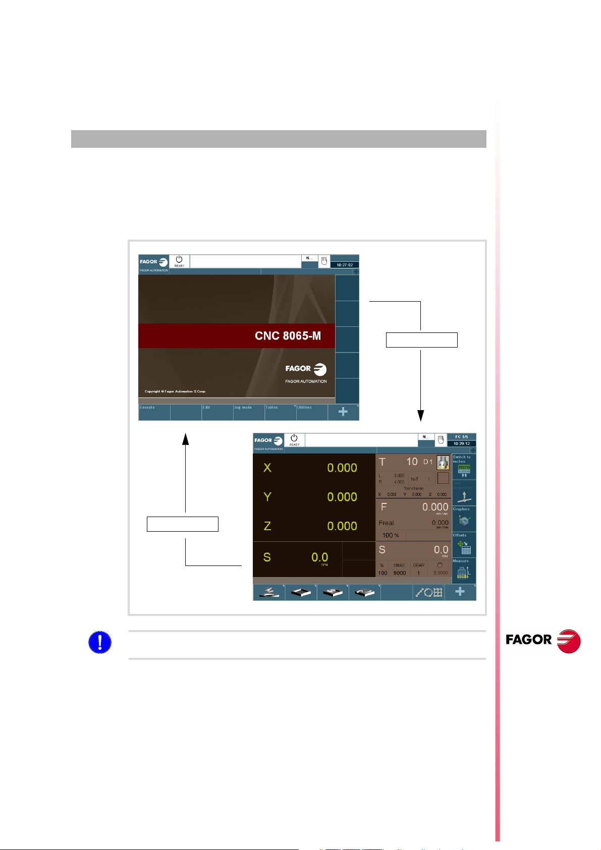
1.2 Keyboard
Vertical and horizontal keyboard
They may be used to select characters, move around various screens and select the various
work modes.
Operating m anual
1.
Keyboard
GENERAL CONCEPTS
A B C D E F
G H I J K L
M N Ñ O P Q
R S T U V W
INS DEL
X Y Z
ENTER
RECALL
ESC
CAPS
SHIFT
CTRL
CUSTOM
789
=
456
/
123
*
_
+
0
HOME
END
SPACE
ALT
EDITMANUALAUTO
TABLES TOOLS UTILITIES
MDI
MAIN
MENU
ESC
Q W E R T Y U I O P
CAPS INS
S D F G H J K L ÑA
ZXCVBNM
<
SPACE
ALTGRALTCTRL
MDI
,.-
RECALL ENTER
UTILITIESTOOLSTABLESEDITM ANUALAUTO
^
.
{}
SHIFTSHIFT
DEL
HOME
END
CUSTOM
=
/
*
+
789
456
123
_
.
0
MAIN
MENU
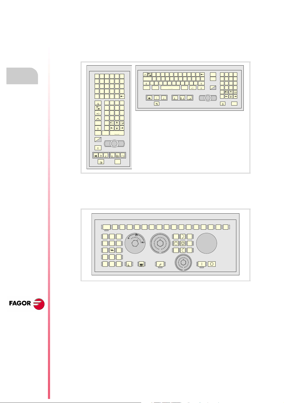
JOG keys
They may be used to move the axes of the machine, govern the spindle, modify the feedrate
of the axes and the spindle speed as well as start and stop the exection.
CNC
8065 TC
(REF: 1201)
CNC
OFF
X+X-Y+ Z+
Y- Z-
7+ 7-
4+ 5+ 6+
4- 5- 6-
jog
1
1
10
10
100
100
1000
10000
ZERO SING LE RESET
70
60
50
40
30
20
10
4
2
0
1009080
+
110
120
130
140
150
160
170
180
190
_
200
FEED
1009080
110
70
120
60
130
50
140
40
150
30
160
20
170
10
180
4
190
2
200
0
SPEED
·26·
Page 27
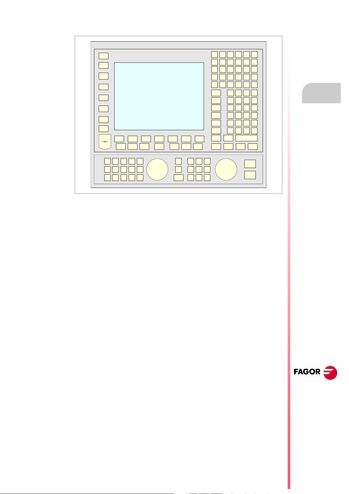
Operating manual
Keyboard set with jog keypad and monitor.
1.
Keyboard
GENERAL CONCEPTS
CNC
8065 TC
(REF: 1201)
·27·
Page 28

1.
Operating m anual
Keyboard
GENERAL CONCEPTS
CNC
8065 TC
(REF: 1201)
·28·
Page 29
OPERATING IN JOG MODE
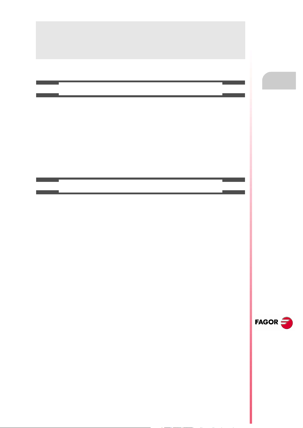
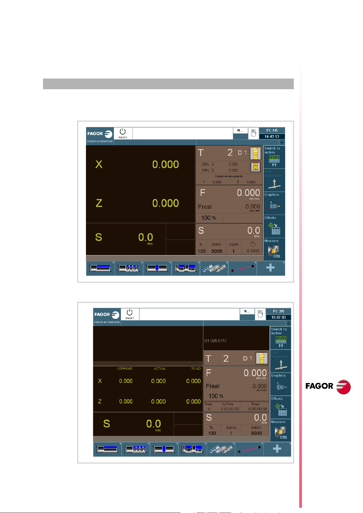
The standard screen of the TC work mode is:
2
When pressing the two-colored key, the CNC shows the auxiliary screen of the TC mode:
CNC
8065 TC
(REF: 1201)
·29·
Page 30
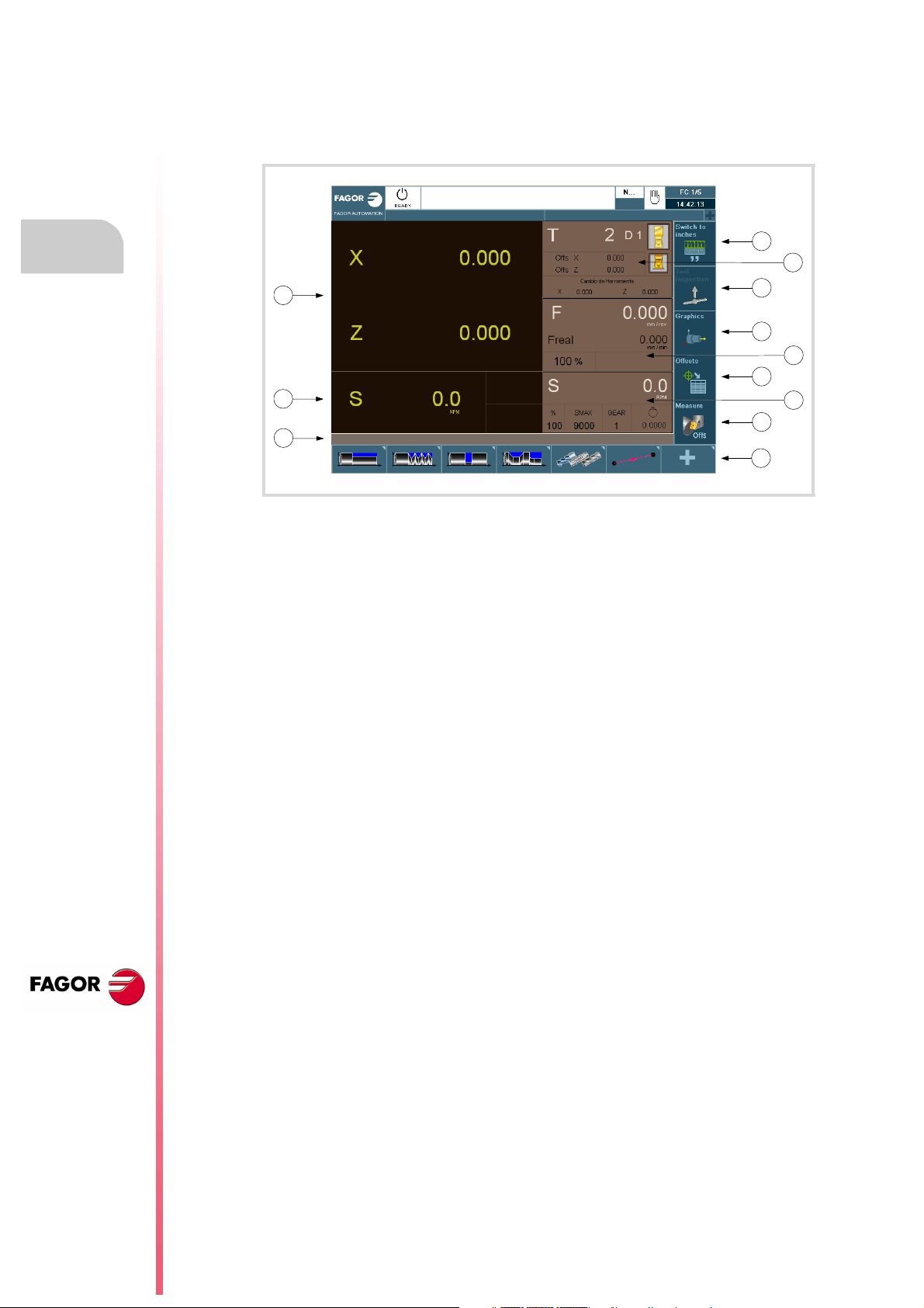
2.1 Introduction
2.1.1 Standard screen of the conversational mode
Operating m anual
2.
OPERATING IN JOG MODE
CNC
8065 TC
(REF: 1201)
Introduction
1
6
12
11
10
1 Softkey for selecting units mm/inches.
2 Softkey to go into tool inspection.
3 Softkey to access the graphics in execution mode.
4 Softkey for selecting OFFSETS.
5 Softkey for tool calibration.
6 Window that shows:
• The selected tool (T).
• Graphic representation of the location code (shape).
• The (D) offset number associated with the selected tool.
• The offset defined for the tool.
• The position values (coordinates) of the tool change point referred to machine
reference zero. If one of these coordinates is selected, it may be assigned the value
of the current position of that axis by pressing [RECALL].
7 Window showing the axis feedrate F currently selected, the % of F being applied and the
real F value. When selecting an incremental jog or a handwheel, this window will also
show the selected % with the corresponding icon and the selected %.
8 Window showing spindle related information:
• The selected theoretical turning speed. S value when working in rpm and CSS value
when working at constant surface speed.
• Spindle status. It is represented with an icon and may be turning clockwise,
counterclockwise or stopped.
• The % of spindle speed being applied.
• Maximum spindle rpm (Smax).
• Active spindle range (gear).
9 Softkeys for cycle editing.
10Message bar.
11Real spindle rpm.
12Position (coordinates) of the axes. The f symbol indicates that the axis is working in
diameter.
2
3
7
4
8
5
9
·30·
If there are more than one spindle in the active channel, S may be pressed repeatedly to
select the spindle whose data is being displayed. If the cell for programmed turning speed
is already selected, every time S is pressed, it will show the data of the next spindle.
Page 31

Operating manual
2.1.2 Auxiliary screen of the conversational mode
14
13
12
11
6
1
7
2
3
8
9
4
10
5
2.
Introduction
1 Softkey for selecting units mm/inches.
2 Softkey to go into tool inspection.
3 Softkey to access the graphics in execution mode.
4 Softkey for selecting OFFSETS.
5 Softkey for tool calibration.
6 Window that shows the status of the G, F, T, D, M functions.
7 Window that shows:
• The selected tool (T).
• Graphic representation of the location code (shape).
• The (D) offset number associated with the selected tool.
8 Window showing the axis feedrate F currently selected, the % of F being applied and the
real F value.
9 Window that shows the value of the variables:
• Partc: It indicates the number of consecutive parts executed with the same partprogram. Every time a new program is selected, this variable is reset to "0".
• CyTime: It indicates the time elapsed while executing the part. It is given in "hours
: minutes : seconds : hundredths of a second" format. Every time a part-program
execution starts, even when repetitive, this variable is reset to "0".
• Timer: It indicates the count of the timer enabled by PLC. It is given in "hours : minutes
: seconds" format.
10Window with spindle related information:
• The selected theoretical turning speed. S value when working in rpm and CSS value
when working at constant surface speed.
• The % of spindle speed being applied.
• Maximum spindle rpm (Smax).
• Active spindle range (gear).
11Message bar.
12Window with spindle related information:
• Theoretical speed.
• Speed in RPM.
• Speed in m/min.
OPERATING IN JOG MODE
CNC
8065 TC
(REF: 1201)
·31·
Page 32

2.
Operating m anual
13Window with axis related information:
• COMMAD: It indicates the programmed coordinate or position that the axis must
reach.
• ACTUAL: It indicates the actual (current) position of the axis.
• TO GO: It indicates the distance which is left to run to the programmed coordinate.
14Window that shows the lines of the program being executed.
Introduction
OPERATING IN JOG MODE
CNC
8065 TC
(REF: 1201)
·32·
Page 33

Operating manual
2.1.3 Cycle editing
To edit a cycle, press the softkey for the desired cycle.
2.
Introduction
OPERATING IN JOG MODE
To select another cycle of the same family as the one selected, press the softkey again to
drop the menu with the available cycles.
Once the cycle to be edited has been selected, enter the data in the windows corresponding
to each parameter of that cycle. To validate each parameter and go on to the next one,
[ENTER].
For further information on editing cycles, see the chapter
cycles"
.
After editing a cycle, it may be simulated, executed or saved using the vertical softkey menu.
For further information on saving cycles, see the chapter
"3 Working with operations or
"5 Saving programs"
.
CNC
8065 TC
(REF: 1201)
·33·
Page 34

2.
Operating m anual
2.1.4 Cycle simulation
To simulate the edited cycle, press the vertical softkey [Simulate cycle].
1
2
3
Introduction
4
OPERATING IN JOG MODE
5
1 Softkey to start cycle simulation.
2 Softkey to stop cycle simulation.
3 Softkey to reset the simulation.
4 Softkey to simulate the cycle block by block.
5 The horizontal softkeys may be used to configure how to display the simulated cycle.
• Type of view.
• Configuration.
• Actions.
• Delete.
• Dimensions.
• Measurement.
CNC
8065 TC
(REF: 1201)
·34·
Page 35

Operating manual
2.1.5 Cycle execution
To execute an edited cycle, press the vertical softkey [Execute cycle]. An icon will then appear
with the start symbol to warn the user that it is going to execute the cycle.
To execute the cycle, press [START]. Otherwise, press [ESC].
2.
Introduction
OPERATING IN JOG MODE
CNC
8065 TC
(REF: 1201)
·35·
Page 36

2.
Operations with the axes.
OPERATING IN JOG MODE
2.2 Operations with the axes.
2.2.1 Home search.
Home search is the operation used to synchronize the system. This operation must be
carried out when the CNC loses the position of the origin point (e.g. by turning the machine
off).
When "searching home", the axes move to the machine reference point and the CNC
assumes the coordinate values assigned to that point by the machine manufacturer, referred
to machine zero. When using distance-coded reference marks or absolute feedback, the
axes will only move the distance necessary to verify their position.
The axes may be homed manually (axis by axis from the operator panel) or automatically
(using a subroutine).
Manual home search (one axis at a time).
The axis-by-axis home search cancels the zero offset, the fixture offset and the measuring offset. The
i
CNC assumes the machine reference zero point (home) as the new part zero.
X Y Z
ZERO
1 Select the axis to be homed using the alphanumeric keyboard. The
CNC will highlight that axis to indicate that it is selected.
To select the numbered axes (e.g. "X1"), select any axis and then move
the selection until positioning on the desired one. The focus moves with
the [©][ª] keys.
2 Press the homing key [ZERO]. The CNC will display the "1" symbol in
the numeric area indicating that a home search will take place.
3 Press [START] to go ahead with the home search or [ESC] to cancel
ESC
the operation.
Operating m anual
CNC
8065 TC
Automatic home search (with subroutine).
This homing method is only available if the machine manufacturer has previously defined
a homing subroutine.
ZERO
1 Press the homing key [ZERO]. The CNC will display a dialog box
requesting confirmation to execute the home search.
2 Press [START] to go ahead with the home search or [ESC] to cancel
ESC
the operation.
(REF: 1201)
·36·
Page 37

Operating manual
2.2.2 Jog
The axes may be jog using the JOG keyboard on the operator panel. The type of jog is
selected with the jog selector switch on the operator panel.
jog
100
1
1
10
jog
10
100
1000
10000
Continuous jog Incremental jog Handwheels
The jog keyboard and the feedrate selector
JOG keypad.
There are two types of jog keyboards depending on the behavior of the keys.
X+X-Y+ Z+
Y- Z-
7+ 7-
X
Y Z
4 5 6
+
The keypad has two keys for each axis. One to jog the axis in the
positive direction and another one to move it in the negative direction.
To move a single axis, press the axis key and the one for its jogging
direction.
The keypad has a key for each axis and two keys for moving direction,
common to all the axes.
To jog an axis requires activating both the axis key and the moving
direction. There are two options, depending on how the jog keyboard
has been configured.
_
• The axis will move while both keys are pressed, the axis key and
the direction key.
• When pressing the axis key, the key remains active. The axis will
move while the direction key is kept pressed. To de-select the axis,
press [ESC] or [STOP].
2.
Operations with the axes.
OPERATING IN JOG MODE
User keys as jog keys
The CNC offers the OEM the possibility to enable the user keys as jog keys. The user keys
defined this way behave like the jog keys.
Feedrate selector.
1009080
70
60
50
40
30
20
10
4
2
200
0
FEED
The movement is carried out at the feedrate defined by the OEM. The
110
feedrate may be varied between 0% and 200% using the feedrate override
120
130
switch on the operator panel.
140
150
160
170
180
190
Movement in continuous jog.
In continuous jog, the axes keep moving while the jog keyboard is acted upon. Continuous
jog allows moving several axes at the same time.
1 Turn the jog selector switch of the operator panel to the continuous jog position on the dial.
2 Jog the desired axis using the JOG panel (keypad). If while moving, a second axis is
selected, the new one will move at the same time and under the same conditions.
If while the axes are moving, the rapid key is pressed, the axes will move at the rapid rate
set by the machine manufacturer. This feedrate will be applied while that key is kept pressed
and, when released, the axes will recover their previous feedrate. This rapid rate may be
varied between 0% and 200% with the feedrate override switch on the operator panel.
CNC
8065 TC
(REF: 1201)
·37·
Page 38

2.
Operating m anual
Movement in incremental jog.
In incremental jog, the axis moves a specific distance every time the key is pressed. In
incremental jog, the axes may be jogged simultaneously.
1 Turn the jog selector switch of the operator panel to one of the incremental jog positions.
Each position will move the axis a fixed distance; the typical values are the following.
Position. Movement for each key push.
1 0.001 mm or 0.0001 inch.
10 0.010 mm or 0.0010 inches.
100 0.100 mm or 0.0100 inches.
1000 1.000 mm or 0.1000 inches.
10000 10.000 mm or 1.0000 inches.
2 Jog the desired axis using the JOG panel (keypad). Every time the JOG panel is acted
upon, the axis will move the distance indicated on the dial of the jog selector switch. If
while moving, a second axis is selected, the new one will move at the same time and
under the same conditions.
Operations with the axes.
OPERATING IN JOG MODE
CNC
8065 TC
(REF: 1201)
·38·
Page 39

Operating manual
2.2.3 Jogging the axes with handwheels
Electronic handwheels may be used to move the axes. Depending on the type of handwheel,
The CNC may have general handwheels to move any axis or individual handwheels that will
only move their associated axes.
To move the axes with the handwheels, turn the jog selector switch of the operator panel to
one of the handwheel positions. Every position indicates the multiplying factor applied to the
handwheel pulses; the typical values are the following.
Position. Movement per revolution of the handwheel.
1 0.100 mm or 0.0100 inches.
10 1.000 mm or 0.1000 inches.
100 10.000 mm or 1.0000 inches.
Once the desired resolution has been selected and depending on the type of handwheel
being used, general or individual, proceed as follows.
2.
General handwheel
The CNC may have several general handwheels. The general handwheel is not associated
with any axis in particular, it may be used to move any axis of the machine even if it has an
individual handwheel associated with it.
• If there are several axes selected in handwheel mode, the general handwheel will move
all of them.
• If an axis has been selected which has an individual handwheel selected with it, this axis
may be moved with the general handwheel, with the individual one or with both at the
same time. When using both handwheels simultaneously, the CNC will add or subtract
the pulses provided by both handwheels depending on which direction they are turned.
• If the CNC has several general handwheels, any of them can move the axes selected
in handwheel mode. When using several handwheels simultaneously, each axis involved
will be applied the sum of the increments of all the handwheels.
These are the steps to follow for moving one or several axes with the general handwheel.
1 Select the axis or axes to be jogged. The CNC will highlight the selected axes. When
selecting an axis or quitting the handwheel mode using the movement selector, the
previous one is automatically deselected.
2 Once the axis has been selected, the CNC will move it as the handwheel is turned
depending on the setting of the selector switch and on the turning direction of the
handwheel.
The feedrate depends on how fast the handwheel is turned.
Selecting the axes to be jogged
Operations with the axes.
OPERATING IN JOG MODE
There are two ways to select the axes.
1 On the JOG keyboard, press one of the keys for the axis to be jogged. Selecting an axis
de-selects the previous one. To select several axes, press one of the keys of each key
at the same time.
An axis needs not belong to the active channel in order to be selected. An axis from one
channel may be set in handwheel mode from another channel, if the channel of the axis
is also in jog mode.
2 When using a handwheel with a push-button, the push-button may be used to select,
sequentially, the axes to be jogged. Pushing the button selects the first one of the axes
being displayed. If an axis has already been selected, it de-selects it and selects the next
one. If it was the last one, it selects the first one again.
Only the axes being displayed in the active channel may be selected, regardless of the
channel they belong to. The axes of another channel cannot be selected if they are not
being displayed.
An axis is de-selected when quitting the handwheel mode using the movement selector and
after a reset. If an axis has been set in handwheel mode from the PLC, it can only be
deactivated from the PLC; a reset does not deactivate it.
CNC
8065 TC
(REF: 1201)
·39·
Page 40

2.
Operations with the axes.
OPERATING IN JOG MODE
Operating m anual
Selecting an axis from the automatic mode
When having only one channel, if while in automatic mode, you set the switch in handwheel
mode and select an axis, when going to jog mode, it maintains the selected axis.
Individual handwheel
The CNC can have several individual handwheels, where each of them is associated with
a particular axis. The CNC moves each axis as its relevant handwheel is turned depending
on the setting of the selector switch and on the turning direction of the handwheel.
In handwheel mode, this symbol next to an axis indicates that the axis has an
individual handwheel associated with it.
When moving several axes simultaneously using handwheels, all the axes having their own
handwheel plus the ones that may be selected with the general handwheel may be involved.
When moving several axes at the same time, the feedrate of each axis depends on how fast
its associated handwheel is turned.
It may happen that depending on the turning speed and the selector position, the CNC be demanded
i
a faster feedrate than the maximum allowed. In that case, the CNC will move the axis the indicated
distance but at the maximum feedrate allowed.
Feed handwheel.
Usually, when machining a part for the first time, the feedrate is controlled by the switch on
the operator panel. The "feed handwheel" allows using one of the handwheels of the machine
to control that feedrate depending on how fast the handwheel is turned.
This feature must be managed from the PLC. Usually, this feature is turned on and off using an external
i
push button or key configured for that purpose.
CNC
8065 TC
(REF: 1201)
·40·
Page 41

Operating manual
2.2.4 Moving an axis to a particular position (coordinate)
X Y Z
ESC
Feedrate behavior
The moving feedrate depends on whether G00 or G01 is active. This feedrate may be varied
between 0% and 200% using the feedrate override switch on the operator panel. The
percentage will be applied on to all the movements carried out in G00 and in G01.
• If G00 is active, the movement is carried out at the rapid rate defined by the machine
manufacturer.
• If G01 is active, the movement is carried out at the active feedrate. If no feedrate is active,
the movement is executed at the feedrate defined by the machine manufacturer.
2.2.5 Coordinate preset
1 Select the axis to be moved using the alphanumeric keyboard. The
CNC will highlight that axis to indicate that it is selected.
To select the numbered axes (e.g. "X1"), select any axis and then move
the selection until positioning on the desired one. The focus moves with
the [©][ª] keys.
2 Enter the coordinate of the target point.
3 Press [START] to execute the movement or [ESC] to cancel the
operation.
2.
Operations with the axes.
OPERATING IN JOG MODE
The coordinates must be preset one axis at a time. The preset may be canceled by homing
the axes one by one or by means of function "G53".
X Y Z
1 Use the alphanumeric keyboard to select the axis whose position value
(coordinate) is to be preset. The CNC will highlight that axis to indicate
that it is selected.
To select the numbered axes (e.g. "X1"), select any axis and then move
the selection until positioning on the desired one. The focus moves with
the [©][ª] keys.
2 Key in the desired preset value.
3 Press [ENTER] to preset the entered value or [ESC] to cancel the
operation.
CNC
8065 TC
(REF: 1201)
·41·
Page 42

2.3 Spindle control
Displaying the data of several spindles.
The screen only shows the data on one spindle. If there are several spindles in the channel,
the data on the next spindle may be displayed by pressing the "S" key. The first push is to
program the turning speed, the second one shows the data on the second spindle and so on.
Operating m anual
2.
Spindle control
OPERATING IN JOG MODE
Spindle control
The spindle may be controlled manually using the following keys of the operator panel. The
keys always refer to the master spindle of the active channel.
The spindle speed should be set (in the MDI mode) before selecting the turning direction,
thus avoiding a sudden start of the spindle when setting an "S" because the turning direction
was active.
Key. Meaning.
Start the spindle clockwise (same as M03 function) at the active speed. The CNC
shows the M03 function in the program history.
Start the spindle counterclockwise (same as M04 function) at the active speed. The
CNC shows the M04 function in the program history.
Stop the spindle (same as M05 function). The CNC shows the M05 function in the
program history.
Orient the spindle (same as M19 function). The CNC shows the M19 function in the
program history.
Vary the speed override from the operator panel.
With the operator panel, it is possible to change the percentage of spindle speed using a
jog keyboard or a switch (depending on model).
Key. Meaning.
Increases or decreases the percentage of spindle speed. The maximum and
_
+
70
60
50
40
30
20
10
4
2
0
SPEED
minimum values as well as the incremental step are set by the OEM, the typical values
being a variation between 50% and 120% with a 5% step.
It sets the percentage of turning speed to be applied. The maximum and minimum
1009080
110
120
values are set by the OEM, the typical values being a variation between 50% and
130
140
120%.
150
160
170
180
190
200
CNC
8065 TC
(REF: 1201)
·42·
Page 43

Operating manual
2.4 Tool selection and tool change
The tool located in the spindle may be changed in manual mode. Proceed as follows.
1 Press [T] at the alphanumeric keyboard. The CNC will highlight the current tool indicating
that it is selected.
2 Key in the number of the tool to be placed in the spindle.
3 Press [START] to execute the tool change or [ESC] to cancel the operation.
2.5 Setting the feedrate and spindle speed.
Setting a new feedrate in the channel.
The feedrate set in jog mode is only applied in that work mode and for the active channel.
When setting a new feedrate in the MDI/MDA mode, it will become the new feedrate for the
jog and automatic modes.
Follow these steps to set a new feedrate.
1 Press [F] at the alphanumeric keyboard. The CNC will highlight the relevant data
indicating that it is selected.
2 Enter the new feedrate.
3 Press [START] to assume the entered value or [ESC] to cancel the operation.
2.
OPERATING IN JOG MODE
Tool selection and tool change
Setting a new spindle speed.
The spindle speed set in the jog mode is applied to the spindle displayed at the time. If there
are several spindles in the channel, the rest of the spindles may be displayed by pressing
the [S] key. The spindle speed set in jog mode is maintained when switching to automatic
mode and vice versa.
Follow these steps to set a new spindle speed.
1 Press [S] at the alphanumeric keyboard until selecting the desired spindle. When
pressing this key for the first time, the CNC will highlight the relevant data indicating that
it is selected.
2 Enter the new spindle speed.
3 Press [START] to assume the entered value or [ESC] to cancel the operation.
CNC
8065 TC
(REF: 1201)
·43·
Page 44

Operating m anual
2.6 Setting and activating the zero offsets and the fixture offsets.
In jog mode, it is possible to save the active offset in the zero offset table or in the fixture offset
table (zero offset, coordinate presetting, etc.) and to activate a zero offset already defined
in the tables.
This softkey shows the zero offsets and the fixture offsets of the system and their value in
each axis of the channel. This list is a brief information of the zero offset tables and fixture
offset tables and any change made in jog mode also affects those tables.
2.
Loading a new zero offset or fixture offset into the table.
With an active offset, use the cursor to select an offset from the list and press [ENTER] to
save the current offset in that zero offset. The position of all the axes of the channel are
updated at the selected zero offset.
Applying a zero offset or fixture offset stored in the table.
Use the cursor to select a zero offset or fixture offset from the list and press the [START] key
to activate. The new zero offset is applied to all the axes of the channel.
OPERATING IN JOG MODE
Setting and activating the zero offsets and the fixture offsets.
CNC
8065 TC
(REF: 1201)
·44·
Page 45

Operating manual
2.7 Tool calibration
Tool calibration is available in the jog mode. The softkey to access tool calibration will be
different depending on the software installed (lathe model or mill model). To quit the
calibration mode and return to jog mode, press the [ESC] key.
Tool calibration in a lathe model.
The CNC offers in both models the possibility to calibrate lathe tools and milling tools. The
CNC will show the necessary data and will update the help graphics according to the selected
tool.
Types of calibration
There are several ways to calibrate a tool. Some ways are only available when using a tabletop probe.
Only manual calibration is possible when not using a table-top probe.
All types of calibration are available when using a table-top probe. The
different calibration methods may be selected from the vertical softkey
menu.
The active kinematics are taken into account and do not prevent tool calibration in this mode.
Manual or semi-automatic calibration will not be possible if a coordinate ( #CS or #ACS)
transformation is active or when either the RTCP or TLC function is active.
Manual calibration. Calibration without a probe.
It is done without the table-top probe. A reference part is required to calibrate the tool. All
the movements are carried out manually.
Semi-automatic calibration. Calibration with a probe.
This calibration mode is available when using a table-top probe. The positioning movements
are carried out manually and the CNC executes the probing movements.
2.
Tool calibration
OPERATING IN JOG MODE
Automatic calibration. Calibration with a probe and a canned cycle.
This calibration mode is available when using a table-top probe. The CNC executes all the
movements using the calibration canned cycle #PROBE.
Probe selection
Two probes may be configured at the CNC. The probe active at the time is used for calibration.
The active probe may be changed via part-program or MDI using the instruction
#SELECT PROBE.
#SELECT PROBE [1]
Selects the first probe.
#SELECT PROBE [2]
Selects the second probe.
CNC
8065 TC
(REF: 1201)
·45·
Page 46

2.
Operating m anual
Geometrical configuration of the axes on a lathe: "plane" or
"trihedron".
At the lathe model, the geometrical configuration of the axes may be either of the "plane"
or "trihedron" type depending on the availability of a third main axis, usually the ·Y· axis. The
different calibration modes adapt to the current configuration showing the necessary data
for each one of them.
Geometrical configuration of "trihedron" type axes.
Y+
X+
Tool calibration
X+
It is the typical configuration of a milling machine or of a lathe
that has a third main axis (·Y· axis).
There are three axes forming a Cartesian XYZ type trihedron
like on a milling machine. There may be more axes besides
Z+
those forming the trihedron.
With this configuration, the planes behave in the same way as
on a milling machine except that the usual work plane will be
G18 (if it has been configured like that).
Geometrical configuration of "plane" type axes.
It is the typical configuration of a lathe.
OPERATING IN JOG MODE
There are two axes forming the usual work plane. There may
be more axes, but they cannot be part of the trihedron; there
Z+
must be auxiliary, rotary, etc.
With this configuration, the active plane will be formed by the
first two axes defined in the channel. If the X (first) and Z
(second) axes have been defined, the work plane will be the ZX
(Z as abscissa and X as ordinate).
The work plane is always G18; the plane cannot be changed
via part-program.
Configuration of "plane" type axes. The longitudinal axis.
In this configuration, the second axis of the channel is considered as longitudinal axis. If the
X (first) and Z (second) axes have been defined, the work plane will be the ZX and Z will be
the longitudinal axis. Tool length compensation is applied on this longitudinal axis when using
milling tools. With lathe tools, tool length compensation is applied on all the axes where a
tool offset has been defined.
When using milling tools on a lathe, the longitudinal compensation axis may be changed by
means of the #TOOL AX instruction or the G20 function.
CNC
8065 TC
(REF: 1201)
·46·
Page 47

Operating manual
2.7.1 Manual calibration. Calibration without a probe
In this mode, only the active tool can be calibrated and it may be a milling tool or a lathe tool.
The CNC will show the necessary data and will update the help graphics according to the
selected tool.
B
2.
C
A
A Machine data. Position of the axes, tool and active tool offset, real spindle speed and real
feedrate of the axes.
B Data of the part used for calibration and drawing showing that calibration is possible. If
the window does not show this drawing, some of the data is missing.
C Necessary data for calibration.
D Tool data.
D
Tool calibration
Since there is no probe, a reference part is required to calibrate the tool. The calibration
consists in moving the tool manually until it touches the part and then validating the calibration
on each axis. After validating them, the new values are saved in the tool table.
Selecting a tool
The tool and the active tool offset may be changed from the calibration mode. After defining
the new tool or tool offset in the cycle data, press [CYCLE START] and the CNC will execute
the tool change.
Tool calibration
OPERATING IN JOG MODE
Bear in mind that if the defined tool is the active tool, when pressing [START] the CNC
assumes the values that the offset has at the time.
Tool calibration in a lathe model (Configuration of plane type axes).
For lathe and mill tools, it calibrates the tool offsets on each axis. When validating the
calibration in one of the offsets, the wear of that offset is reset to zero.
Tool calibration in a lathe model (Configuration of trihedron type axes).
• For the lathe tools, it calibrates the tool offsets on each axis. When validating the
calibration in one of the offsets, the wear of that offset is reset to zero.
• There are two options for the milling tools and may be selected with the following icons.
Tool length calibration. This option may be used to update the length value
and resets the wear value to zero. It also updates the tool table data.
Tool offset calibration. This option may be used to update the value of the
offsets on each axis. The offset wears are set to zero.
CNC
8065 TC
(REF: 1201)
·47·
Page 48

2.
Operating m anual
Validating the calibration.
They are validated from the vertical softkey menu. Once the tool has been calibrated, when
pressing [START] the CNC assumes the new values of the offset.
Softkey. Description.
Validating the length calibration of a milling tool.
Validating the offsets of a milling tool.
Validating the offsets of a lathe tool.
Tool calibration
OPERATING IN JOG MODE
When on a lathe the axis have a "trihedron" type configuration, the calibration on the axis
perpendicular to the work plane is done using the horizontal softkey menu.
Definition of data
To define the data, place the focus on the relevant data, key in the desired value and press
[ENTER].
For a lathe tool.
The nomenclature of the axes depends on the geometrical configuration of the "plane" or
"trihedron" axes. For a "plane" configuration, the nam es of the axes assume the DIN standard
for lathes; the Z axis as the abscissa axis and the X axis as the ordinate axis.
Data Meaning
Zp Xp Dimensions of the reference part being used in the calibration. These coordinates
are referred to the main axes of the tool.
T Tool to be calibrated.
D Tool offset to be calibrated.
Off Y
Off X
Lw Offset wear on each axis.
Tool offsets on each axis.
CNC
8065 TC
(REF: 1201)
·48·
When a lathe has a third axis perpendicular to the work plane ("trihedron" geometrical
configuration), the CNC will also show its data and calibration will be possible on that axis.
The data of the third axis may be hidden or shown using the horizontal softkey menu.
For a milling tool.
Data Meaning
Zp Coordinate of the reference part being used in the calibration. This coordinate is
referred to the longitudinal axis of the tool.
T Tool to be calibrated.
D Tool offset to be calibrated.
LTool length.
Lw Length wear.
R Tool radius.
Rw Radius wear.
Page 49

Operating manual
Tool calibration steps
To calibrate the length, follow these steps.
1 Define the dimensions of the reference part being used in the calibration.
2 Select the tool and the offset to be calibrated. After the selection, the CNC shows the
dimensions defined in the tool table for that offset.
To calibrate a tool, it must be the active tool. When selecting a tool and pressing [ENTER],
the CNC only shows the data for that tool. Press [CYCLE START] for the CNC to make
the tool change so it becomes the active tool. See
3 Calibrate the tool. Approach the tool manually until touching the part and then validate
the calibration using the softkey menu.
After validating the calibration, it updates the values and initializes the wear value to zero.
Them, the new values are saved in the tool table.
4 Press [START] for the CNC to assume the new values of the offset.
"Selecting a tool"
on page 47.
2.
To calibrate another tool, repeat steps 2 and 3.
Considerations for the offsets and their wear.
It must be borne in mind that the offset of a tool on an axis is the distance between the base
of the tool and its tip (nose). This means that when calculating the offset of a milling tool on
an axis that includes the radius dimension, that radius is included in the offset. The same
is true for the tool length.
When calibrating the offsets of a milling tool, the length value is deleted but not the radius
value.
Sign criteria for the offsets and their wear.
The sign criterion for the offsets and their wear is established by machine parameter
TOOLOFSG.
TOOLOFSG Meaning.
Negative. Tool calibration returns a negative offset. The offset wear must be entered with
a positive value.
Positive. Tool calibration returns a positive offset. The offset wear must be entered with
a negative value.
Entering wear values incrementally or absolutely.
In the tool table, it is possible to define whether the wear value being entered must be
incremental or absolute.
Tool calibration
OPERATING IN JOG MODE
Using incremental wear, the value entered by the user will be added (or subtracted if it is
negative) to the absolute value of the wear. After pressing [ENTER] to accept the new value,
the wear field will show the resulting absolute value.
Initial wear Incremental wear Total wear
10.21.2
1-0.20.8
-1 0.2 -0.8
-1 -0.2 -1.2
CNC
8065 TC
(REF: 1201)
·49·
Page 50

2.7.2 Semi-automatic calibration. Calibration with a probe
This option is only available when using a tabletop probe installed on the machine. On a lathe
model, it may be used to calibrate the offsets of any tool.
Operating m anual
B
2.
Tool calibration
OPERATING IN JOG MODE
C
A
A Machine data. Position of the axes, tool and active tool offset, real spindle speed and real
feedrate of the axes.
B Data of probing movement.
C Necessary data for calibration.
The tool must be in the spindle. After the calibration, the wear is reset to zero.
When changing the tool data, the tool table data is updated after calibration.
Tool calibration
The calibration consists in manually approaching the tool to the probe and then command
the CNC to execute the probing movement. The CNC will move the tool on the selected axis
until touching the probe. After touching the probe, it concludes the calibration on that axis
and updates the values.
CNC
8065 TC
(REF: 1201)
Selecting a tool
The tool and the active tool offset may be changed from the calibration mode. After defining
the new tool or tool offset in the cycle data, press [CYCLE START] and the CNC will execute
the tool change.
Bear in mind that in this calibration mode, the [CYCLE START] key has two functions. If a
new tool has been selected, it executes the tool change. If the selected tool is the active one,
pressing [CYCLE START] initiates the calibration.
Tool calibration
For lathe and mill tools, it calibrates the tool offsets on each axis. When validating the
calibration in one of the offsets, the wear of that offset is reset to zero.
Validating the calibration
Use the horizontal softkey menu to select the axis and the moving direction for the calibration.
Once selected and after placing the tool in the spindle, press [CYCLE START] to start the
calibration. The tool will move in the indicated direction until touching the probe and it will
then conclude the calibration updating the tool data with the measured values.
Once the tool has been calibrated, the CNC shows a message proposing to press [START]
so the CNC assumes the new values of the offset. When pressing [START] while this
message is displayed, the CNC assumes the new values of the offset; if the message is not
displayed, pressing [START] executes the probing movement again.
Once a movement has been selected, the window will show a help drawing indicating the
type of calibration to be done.
·50·
Page 51

Operating manual
Definition of data
To define the data, place the focus on the relevant data, key in the desired value and press
[ENTER].
Data Meaning
PRBMOVE Maximum probing distance. If the CNC does not receive the probe signal before
F Probing feedrate.
T Tool to be calibrated.
D Tool offset to be calibrated.
Off X
Off Z
reaching moving this probing distance, it stops the axes.
2.
Tool offsets on each axis.
Tool calibration steps
To calibrate the tool, follow these steps:
1 Define the probing distance and feedrate. If the feedrate is not defined, the probing
movement will be made at the feedrate set by the OEM.
2 Select the tool and the offset to be calibrated. After the selection, the CNC shows the
dimensions defined in the tool table for that offset.
To calibrate a tool, it must be the active tool. When selecting a tool and pressing [ENTER],
the CNC only shows the data for that tool. Press [CYCLE START] for the CNC to make
the tool change so it becomes the active tool. See
3 Manually approach the tool to the probe until it is placed on the path that will be used
for probing.
4 Calibrate the tool. Select the axis and the probing direction on the softkey menu and press
[START].
The probe moves in parallel to the axis and in the selected direction until touching the
probe. It updates the measured value and resets the wear value to zero. The data is stored
in the tool table.
5 Press [START] again for the CNC to assume the new values of the offset. For the new
values to be assumed, press [START] while the bottom message is displayed; otherwise,
it executes the probing movement again.
"Tool calibration"
on page 50.
Considerations for the offsets and their wear.
Tool calibration
OPERATING IN JOG MODE
It must be borne in mind that the offset of a tool on an axis is the distance between the base
of the tool and its tip (nose). This means that when calculating the offset of a milling tool on
an axis that includes the radius dimension, that radius is included in the offset. The same
is true for the tool length.
When calibrating the offsets of a milling tool, the length value is deleted but not the radius
value.
Sign criteria for the offsets and their wear.
The sign criterion for the offsets and their wear is established by machine parameter
TOOLOFSG.
TOOLOFSG Meaning.
Negative. Tool calibration returns a negative offset. The offset wear must be entered with
a positive value.
Positive. Tool calibration returns a positive offset. The offset wear must be entered with
a negative value.
Entering wear values incrementally or absolutely.
In the tool table, it is possible to define whether the wear value being entered must be
incremental or absolute.
CNC
8065 TC
(REF: 1201)
·51·
Page 52

2.
Operating m anual
Using incremental wear, the value entered by the user will be added (or subtracted if it is
negative) to the absolute value of the wear. After pressing [ENTER] to accept the new value,
the wear field will show the resulting absolute value.
Initial wear Incremental wear Total wear
10.21.2
1-0.20.8
-1 0.2 -0.8
-1 -0.2 -1.2
Tool calibration
OPERATING IN JOG MODE
CNC
8065 TC
(REF: 1201)
·52·
Page 53

Operating manual
2.7.3 Automatic calibration with a probe and a canned cycle (“plane” geometric configuration)
This option is only available when using a tabletop probe installed on the machine. This mode
may be used to calibrate both milling and lather tools. The CNC will show the necessary data
and will update the help graphics according to the selected tool.
B
C
A
2.
Tool calibration
OPERATING IN JOG MODE
A Machine data. Position of the axes, tool and active tool offset, real spindle speed and real
feedrate of the axes.
B Tool to be calibrated.
C Data for probe calibration and position.
Tool calibration
The calibration is done using a probing canned cycle. The CNC moves the tool until touching
the probe and validates the calibration on each axis. The tool is calibrated on the two axes
of the plane.
The calibration begins when pressing the [CYCLE START] key. When the CNC finishes the
calibration on the selected axes, it updates the dimensions and the wears. Them, the new
values are saved in the tool table.
Selecting a tool
In this calibration mode, the cycle itself changes the tool and the tool offset. There is no need
to previously place the tool in the spindle.
Bear in mind that pressing the [CYCLE START] key starts the calibration cycle.
Select another position for the probe.
The calibration uses the probe position defined in the machine parameters.
Optionally, another position may be defined for the probe which will only be valid
for the defined calibration. The new position does not affect the values defined
in the machine parameters.
Tool calibration
For milling and lathe tools, it calibrates the tool offsets on each axis. The offset wears are
set to zero.
CNC
8065 TC
(REF: 1201)
·53·
Page 54

2.
Tool calibration
OPERATING IN JOG MODE
Operating m anual
Definition of data
To define the data, place the focus on the relevant data, key in the desired value and press
[ENTER]. To change icons, place the focus on it and press [SPACE].
Data Meaning
T Tool to be calibrated.
D Tool offset to be calibrated.
Ds Safety distance.
F Probing feedrate.
If not defined, the movements are carried out at the default feedrate, set by the
machine manufacturer.
PRB1MAX
···
PRB2MIN
Probe position.
The values defined here are only taken into account during the calibration cycle; they
do not modify the machine parameter values.
Tool calibration steps
To calibrate the length, follow these steps.
1 Select the tool and the offset to be calibrated. It is not necessary to insert the tool into
the spindle; the CNC carries out this operation if necessary.
2 Define the data defining the calibration.
3 Press the [CYCLE START] key to start the calibration. The CNC calibrates the tool making
all the necessary movements; there is no need to manually approach the tool. If
necessary, the CNC makes the tool change.
4 After the calibration It updates the tool table data.
CNC
8065 TC
(REF: 1201)
·54·
Page 55

Operating manual
2.7.4 Automatic calibration with a probe and a canned cycle (“trihedron” geometric configuration)
This option is only available when using a tabletop probe installed on the machine. This mode
may be used to calibrate both milling and lather tools. The CNC will show the necessary data
and will update the help graphics according to the selected tool.
B
C
2.
Tool calibration
A
A Machine data. Position of the axes, tool and active tool offset, real spindle speed and real
feedrate of the axes.
B Tool to be calibrated.
C Data for probe calibration and position.
D Data for tool wear measurement.
D
Tool calibration
The calibration is done using a probing canned cycle. The CNC moves the tool until touching
the probe and validates the calibration on each axis. The tool may be calibrated on both axes
of the plane or on the three axes of the trihedron.
The calibration begins when pressing the [CYCLE START] key. When the CNC finishes the
calibration on the selected axes, it updates the tool table with the measured values. Also,
the CNC assumes the new values.
Selecting a tool
In this calibration mode, the cycle itself changes the tool and the tool offset. There is no need
to previously place the tool in the spindle.
OPERATING IN JOG MODE
Bear in mind that pressing the [CYCLE START] key starts the calibration cycle.
Select another position for the probe.
The calibration uses the probe position defined in the machine parameters.
Optionally, another position may be defined for the probe which will only be valid
for the defined calibration. The new position does not affect the values defined
in the machine parameters.
Tool calibration
There are two options for the milling tools and may be selected with the following icons.
• Calibrate the offsets and resets the wears to zero.
• Calibrate the length and radius and measure the wears.
For the lathe tools, it calibrates the tool offsets on each axis. The offset wears are set to zero.
CNC
8065 TC
(REF: 1201)
·55·
Page 56

Operating m anual
Definition of data
To define the data, place the focus on the relevant data, key in the desired value and press
[ENTER]. To change icons, place the focus on it and press [SPACE].
To calibrate the length, radius and wears of a milling tool.
The data shown depends on the calibration option selected with the horizontal softkey menu.
This menu may be used to select the length and/or radius calibration and whether to calculate
their wear or not. If the wears are not calculated, they are reset to zero after the calibration.
2.
Tool calibration
OPERATING IN JOG MODE
Data Meaning
T Tool to be calibrated.
D Tool offset to be calibrated.
Ds Safety distance.
F Probing feedrate.
If not defined, the movements are carried out at the default feedrate, set by the
machine manufacturer.
N Number of cutters of the tool.
If defined with a ·0· value, the CNC knows the location of a cutter and it will only make
the movement once. The spindle turning speed must be ·0·.
If defined with a value other than ·0·, all cutters will be calibrated. The CNC makes
an initial movement to locate a cutter; then, stops the spindle and makes a precise
measurement of each cutter. It is necessary to define the spindle speed and the Dm
distance.
Dm Distance the edge of the tool separates from the center of the probe to position the
next cutter.
S Spindle speed.
Probe side to be touched.
Behavior when exceeding the maximum wear permitted; reject the tool or change it
with another one from the same family.
Lw Maximum length wear allowed.
Rw Maximum radius wear allowed.
PRB1MAX
···
PRB2MIN
Probe position.
The values defined here are only taken into account during the calibration cycle; they
do not modify the machine parameter values.
CNC
8065 TC
(REF: 1201)
To calibrate the offsets of a milling or lathe tool.
Data Meaning
T Tool to be calibrated.
D Tool offset to be calibrated.
Ds Safety distance.
F Probing feedrate.
If not defined, the movements are carried out at the default feedrate, set by the
machine manufacturer.
PRB1MAX
···
PRB2MIN
Probe position.
The values defined here are only taken into account during the calibration cycle; they
do not modify the machine parameter values.
This icon sets the number of axes to calibrate on.
·56·
Page 57

Operating manual
Tool calibration steps
To calibrate the length, follow these steps.
1 Select the tool and the offset to be calibrated. It is not necessary to insert the tool into
the spindle; the CNC carries out this operation if necessary.
2 Define the data defining the calibration. To calibrate a milling tool, use the horizontal
softkey menu to select the desired operation.
3 Press the [CYCLE START] key to start the calibration. The CNC calibrates the tool making
all the necessary movements; there is no need to manually approach the tool. If
necessary, the CNC makes the tool change.
4 After the calibration It updates the tool table data.
2.
Tool calibration
OPERATING IN JOG MODE
CNC
8065 TC
(REF: 1201)
·57·
Page 58

2.
Operating m anual
Tool calibration
OPERATING IN JOG MODE
CNC
8065 TC
(REF: 1201)
·58·
Page 59

WORKING WITH OPERATIONS OR CYCLES
3.1 Canned cycles available in the editor.
Select the machining cycles.
The machining cycles integrated into the cycle editor are grouped as follows. When pressing
one of these softkeys, the editor shows the cycle of that group used last. When pressing the
same softkey again, the menu shows all the cycles of the group.
Turning.
Simple turning, turning with vertex rounding, simple facing, facing with
vertex rounding, vertex chamfering, chamfering between points, vertex
rounding and rounding between points.
Tapping.
Longitudinal threading, taper threading, face threading, thread repair
aand multiple-entry (multi-start) threads.
3
Grooving.
Simple longitudinal grooving, simple face grooving, inclined longitudinal
grooving, inclined face grooving and cut-off.
Profiles.
Point-to-point turning, profile turning, ZC plane profile, ZC/YZ pocket
cycles, XC plane profile and XC/XY pocket cycles.
Z axis machining.
Drilling, tapping, multiple drilling, multiple threading, multiple slot milling
Positioning.
Positioning and positioning with M functions.
Activating the Teach-in mode.
The "+" softkey shows the softkey to activate the teach-in mode that allows
jogging the axes of the machine and entering the actual (real) position of
the axes into the data. See
Configuring the cycle editor.
The "+" softkey shows the softkey to configure some of the options of the
cycles of the editor.
Accessing the probing cycles.
The "+" softkey shows the softkey to access the probing cycles or the mill
model cycles (if they are available).
"3.1.2 Teach-in mode."
on page 61.
CNC
8065 TC
(REF: 1201)
·59·
Page 60

3.
Operating m anual
3.1.1 Configuring the cycle editor.
The "+" softkey shows the softkey to configure some of the options of the
cycles of the editor.
Programming M functions in each operation.
Enable the programming of M functions in the canned cycles, to execute them before each
machining operation. This permits, for example, to execute subroutines associated with M
functions before the various operations.
Being this option active, the editor offers in each operation of the cycle the option to edit up
to 4 M functions. To execute only one of them, define it first and leave the rest of the data
unprogrammed.
On the cycle screens, the display must be activated in order to see and define
the M function data; otherwise, the data will not be displayed.
Select the graphics for a vertical lathe.
Enable the cycles for vertical lathe.
Canned cycles available in the editor.
Cycle editor configured for horizontal lathe.
WORKING WITH OPERATIONS OR CYCLES
Cycle editor configured for vertical lathe.
Select axis configuration.
Setting an axis configuration for the cycle editor. The defined axis
configuration is only valid for making it easier to edit the cycle because
it shows the data related to the coordinates according to the chosen
axis configuration.
The canned cycles have no work plane associated with them, they are
executed in the current active work plane.
CNC
8065 TC
(REF: 1201)
·60·
Page 61

Operating manual
3.1.2 Teach-in mode.
Being this mode active, the bottom of the cycle editor shows a window with the actual axis
position and the active machining conditions. The information in the window cannot be
configured, it is not conditioned by the configuration made in the EDISIMU mode for the
teach-in mode.
When teach-in mode is active, it is possible to keep editing the data of the axes directly from
the keyboard or they may be assigned the actual position of the axes. Both editing methods
may be used indistinctly, even while defining a cycle. To assign the position of its axis to a
data, proceed as follows:
1 Select one of the data with the cursor.
2 Move the axes to the desired position using the jog keys, the handwheels or the MDI/MDA
mode.
3 Press the [RECALL] key. The editor enters the actual position of the corresponding axis
into the selected data.
The "+" softkey shows the softkey to activate the teach-in mode that allows
jogging the axes of the machine and entering the actual (real) position of
the axes into the data. The reset of the data must be edited manually.
3.
Canned cycles available in the editor.
WORKING WITH OPERATIONS OR CYCLES
CNC
8065 TC
(REF: 1201)
·61·
Page 62

3.
Operating m anual
3.1.3 Selecting data, profiles and icons
Data selection.
To enter or modify a data, it must be selected; i.e. it must have the editing focus on it.
The parameters of the cycles may be selected with the [§] [¨] [©] [ª] keys or with the direct
access keys. The first data of each group may also be selected by pressing the page-up and
page-down keys.
The direct access keys correspond to the name of the parameters; [F] for feedrates, [T] for
tools, etc. Every time the same key is pressed, it selects the next data of the same type.
Data entry.
Place the cursor in the corresponding window, key in the desired value and press [ENTER].
If [ENTER] is not pressed, the new value will not be assumed.
If the Teach-in mode is selected, the current position of the machine may be associated with
a coordinate. Place the cursor in the relevant window and press the [RECALL] key.
For the X axis parameters, it will take the coordinate of the first axis of the channel where
the edit-simulation mode is active. For the Y axis parameters, the coordinate of the second
axis and for the Z axis parameters, the coordinate of the third one.
Changing the state of an icon.
Canned cycles available in the editor.
WORKING WITH OPERATIONS OR CYCLES
Place the cursor on the desired icon and press the space bar.
Go to the tool table.
Pressing [RECALL] on a tool gives access to the tool table and to the data of that tool.
Select - Define a profile.
To select or modify a profile, the corresponding data must be selected; i.e. it must have the
editing focus on it.
• To select an existing profile, press the [ª] key to expand the list of defined profiles and
select one or type its name.
• To define a new profile, write the desired name and press the [RECALL] key to access
the profile editor.
• To modify an existing profile, select it from the list or write its desired name and press
the [RECALL] key to access the profile editor.
• To delete a profile, press the [ª] key to expand (drop) the list of profiles and select one.
Press the [DEL] key to delete it.
CNC
8065 TC
(REF: 1201)
·62·
Page 63

Operating manual
3.1.4 Definition of spindle conditions
Work mode (RPM) or (CSS)
Use the [§][¨][©][ª] keys to place the cursor on the icon and press the
[SPACE] key to change the type of work.
Spindle range
Place the cursor over this data, key in the desired value and press [ENTER].
Maximum spindle speed (S) in rpm
Place the cursor over this data, key in the desired value and press [ENTER].
Spindle turning direction.
Use the [§][¨][©][ª] keys to place the cursor on the icon and press the
[SPACE] key to change the type of work.
3.
Canned cycles available in the editor.
The CNC starts the spindle and assumes that turning direction as the data
for the cycle's spindle turning direction
Coolant
Use the [§][¨][©][ª] key to place the cursor on the icon and press the [SPACE] key to
change the icon.
It involves activating the coolant. The CNC outputs the M8 function to the PLC
Means turning the coolant off. The CNC outputs the M9 function to the PLC.
Once the operation or the cycle is completed or the part-program it belongs to, the CNC
outputs the M9 function to the PLC.
WORKING WITH OPERATIONS OR CYCLES
CNC
8065 TC
(REF: 1201)
·63·
Page 64

3.
Operating m anual
3.1.5 Definition of machining conditions
Some cycles maintain the same machining conditions during the whole execution process
(positioning cycle, drilling cycle ...)
Other cycles use machining cycles for roughing and other conditions for finishing ,(turning
cycle, rounding cycle, ...)
This section shows how all this data has to be defined.
Axis feedrate (F)
Place the cursor over this data, key in the desired value and press [ENTER].
Spindle turning speed (S)
Place the cursor over this data, key in the desired value and press [ENTER].
Tool for machining (T)
Place the cursor over this data, key in the desired value and press [ENTER].
The CNC updates the associated "D" offset and the adjacent icon, displaying the graphic
representation for the location code associated with the new tool.
Tool offset number (D)
Canned cycles available in the editor.
WORKING WITH OPERATIONS OR CYCLES
Place the cursor over this data, key in the desired value and press [ENTER].
Roughing Pass (∆)
Place the cursor over this data, key in the desired value and press [ENTER].
Finishing Stock (δ)
Place the cursor over this data, key in the desired value and press [ENTER].
Machining direction
Some cycles allow the machining direction to be selected (turning direction or facing
direction).
Turning direction Facing direction
To do this, move onto this icon and press the [SPACE] key. The icon changes and the help
graph is updated.
CNC
8065 TC
(REF: 1201)
·64·
Activate or deactivate roughing, semi-finishing, finishing or wear measurement
Activates or deactivates the roughing or finishing operations.
If the finishing operation is deactivated and you don't want to leave finishing stocks, enter
"0" in the corresponding boxes.
Page 65

Operating manual
3.2 Positioning cycle.
Definition of data
3.
Positioning cycle.
Type of positioning:
Select the type of positioning
Type of feedrate:
Feedrate at the programmed F
In rapid traverse
Spindle rotation:
Spindle stopped.
It is possible to select the spindle turning direction or carry out the cycle with the spindle
stopped.
Coordinates of the target point (X, Z):
There are 2 ways to select the coordinates:
• Manually enter the value
X, Z Target point
WORKING WITH OPERATIONS OR CYCLES
• Assign the present position of the machine.
Activate the Teach-in mode. The bottom screen shows the tool
position.
Use the handwheel or the jog keys to move the axis to the desired point.
Press [RECALL] to assume the value shown on the screen.
CNC
8065 TC
(REF: 1201)
·65·
Page 66

3.
Operating m anual
3.3 Positioning cycle with M functions.
Definition of data
Positioning cycle with M functions.
WORKING WITH OPERATIONS OR CYCLES
Type of positioning:
Select the type of positioning
Type of feedrate:
Feedrate at the programmed F
In rapid traverse
Spindle rotation:
Spindle stopped.
It is possible to select the spindle turning direction or carry out the cycle with the spindle
stopped.
Coordinates of the target point (X, Z):
There are 2 ways to select the coordinates:
• Manually enter the value
X, Z Target point
CNC
8065 TC
(REF: 1201)
·66·
• Assign the present position of the machine.
Activate the Teach-in mode. The bottom screen shows the tool
position.
Use the handwheel or the jog keys to move the axis to the desired point.
Press [RECALL] to assume the value shown on the screen.
The auxiliary functions “M” which will be executed before and after positioning:
Auxiliary function “M” is the name given to the functions determined by the manufacturer
which allow the different machine devices to be governed.
Up to 12 auxiliary functions may be defined, 6 before executing the movement and 6 after
executing the movement
The functions will be executed in the same order as these are arranged on the list.
Page 67

Operating manual
3.4 Simple turning cycle.
Definition of geometry
Type of turning: internal or external:
External turning.
Internal turning.
Each time the turning type is changed, the CNC modifies the icon and displays the relevant
geometry help screen.
3.
Simple turning cycle.
Coordinates of the starting point (Xi, Zi) and coordinates of the end point (Xf, Zf):
There are 2 ways to select the coordinates:
• Manually enter the value
Xi, Zi Coordinates of the starting point
Xf, Zf Coordinates of the end point. By default, Xf assumes the value set for Xi.
• Assign the present position of the machine.
Activate the Teach-in mode. The bottom screen shows the tool
position.
Use the handwheel or the jog keys to move the axis to the desired point.
Press [RECALL] to assume the value shown on the screen.
Final diameter (Φ):
Φ Final diameter.
Safety distance:
In order to prevent collisions with the part, the CNC allows a part approach point to be set.
The safety distance indicates the approach point coordinate with respect to the starting point
(Xi, Zi).
DX, DZ Safety distance.
The value of the safety distance on X is always defined in radius.
WORKING WITH OPERATIONS OR CYCLES
CNC
8065 TC
(REF: 1201)
·67·
Page 68

3.
Operating m anual
Machining parameters
Machining feedrate (F):
F Machining feedrate.
Spindle turning speed (S):
S Spindle speed.
Maximum machining pass (∆):
∆ Maximum roughing pass.
Finishing stocks (δx,δz):
δx Finishing stock in X.
δz Finishing stock in Z.
Simple turning cycle.
WORKING WITH OPERATIONS OR CYCLES
CNC
8065 TC
(REF: 1201)
·68·
Page 69

Operating manual
3.4.1 Basic operation
The machining steps in this cycle are as follows:
1 If the roughing operation was programmed with another tool the CNC makes a tool
change, moving to the change point if the machine so requires.
2 The spindle starts with the speed selected and in the direction stated.
3 The tool approaches the starting point (Xi, Zi) in rapid, keeping the selected safety
distance according to axes X and Z.
4 Roughing operation, by successive turning passes, to a distance from the final diameter
selected equal to the finishing excess material. This operation is done with the conditions
set for the roughing operation.
If ∆ is positive, the CNC calculates the real pass so all the turning passes are identical.
This pass will be equal to or under the defined value ∆.
If ∆ is negative, the passes are run with the programmed value, except the last one that
machines the rest.
Each turning pass is done as shown in the figure, starting at point "1" and after going
through points "2", "3" and "4", ending at point "5".
3.
Simple turning cycle.
WORKING WITH OPERATIONS OR CYCLES
5 Finishing operation.
If the finishing operation was programmed with another tool, the CNC will make a tool
change, moving to the change point if the machine so requires.
The part finishing is done with the machining conditions set for finishing; axis feedrate
(F), spindle speed (S), turning direction.
6 Once the operation or cycle has ended, the tool will return to the safety point.
CNC
8065 TC
(REF: 1201)
·69·
Page 70

3.
Operating m anual
7 The CNC will not stop the spindle but keeps the machining conditions set for finishing
selected; tool (T), axis feedrate (F) and spindle speed (S).
Considerations
If T0 is selected as roughing tool, the cycle does not execute the roughing operation. This
means that after approaching the finishing operation will be carried out.
If T0 is selected as finishing tool, the cycle does not execute the finishing operation. This
means that, after the roughing operation, the tool will move to the approach point, keeping
the safety distance with respect to the starting point (Xi, Zi).
When the surface to be machined is not fully cylindrical, the CNC analyzes the coordinates
on X of the starting and end points and takes as starting point on X the coordinate farthest
from the final diameter.
Simple turning cycle.
WORKING WITH OPERATIONS OR CYCLES
The roughing operation is carried out in G05, the rounding radius may be modified using the
instruction #ROUNDPAR. If not programmed, it assumes the default rounding radius set by
machine parameters.
The finishing operation is carried out in G07.
CNC
8065 TC
(REF: 1201)
·70·
Page 71

Operating manual
3.5 Turning cycle with vertex rounding.
Definition of geometry
Type of turning: internal or external:
External turning.
Internal turning.
3.
Each time the turning type is changed, the CNC modifies the icon and displays the relevant
geometry help screen.
Coordinates of the starting point (Xi, Zi) and coordinates of the end point (Xf, Zf):
There are 2 ways to select the coordinates:
• Manually enter the value
Xi, Zi Coordinates of the starting point
Xf, Zf Coordinates of the end point. By default, Xf assumes the value set for Xi.
• Assign the present position of the machine.
Activate the Teach-in mode. The bottom screen shows the tool
position.
Use the handwheel or the jog keys to move the axis to the desired point.
Press [RECALL] to assume the value shown on the screen.
Final diameter (Φ):
Φ Final diameter.
Corners (P1, P2, P3):
Change the shape of the corner with the [SPACE] key and enter the radius
or the chamfer distance.
Turning cycle with vertex rounding.
WORKING WITH OPERATIONS OR CYCLES
Safety distance:
In order to prevent collisions with the part, the CNC allows a part approach point to be set.
The safety distance indicates the approach point coordinate with respect to the starting point
(Xi, Zi).
DX, DZ Safety distance.
The value of the safety distance on X is always defined in radius.
CNC
8065 TC
(REF: 1201)
·71·
Page 72

3.
Operating m anual
Machining parameters
Machining feedrate (F):
F Machining feedrate.
Spindle turning speed (S):
S Spindle speed.
Turning cycle with vertex rounding.
WORKING WITH OPERATIONS OR CYCLES
Maximum machining pass (∆):
∆ Maximum roughing pass.
Finishing stocks (δx,δz):
δx Finishing stock in X.
δz Finishing stock in Z.
CNC
8065 TC
(REF: 1201)
·72·
Page 73

Operating manual
3.5.1 Basic operation
The machining steps in this cycle are as follows:
1 If the roughing operation was programmed with another tool the CNC makes a tool
change, moving to the change point if the machine so requires.
2 The spindle starts with the speed selected and in the direction stated.
3 The tool approaches the starting point (Xi, Zi) in rapid, keeping the selected safety
distance according to axes X and Z.
4 Roughing operation, by successive turning passes, to a distance from the final diameter
selected equal to the finishing excess material. This operation is done with the conditions
set for the roughing operation.
If ∆ is positive, the CNC calculates the real pass so all the turning passes are identical.
This pass will be equal to or under the defined value ∆.
If ∆ is negative, the passes are run with the programmed value, except the last one that
machines the rest.
Each turning pass is done as shown in the figure, starting at point "1" and after going
through points "2", "3" and "4", ending at point "5".
3.
Turning cycle with vertex rounding.
WORKING WITH OPERATIONS OR CYCLES
5 Finishing operation.
If the finishing operation was programmed with another tool, the CNC will make a tool
change, moving to the change point if the machine so requires.
The part finishing is done with the machining conditions set for finishing; axis feedrate
(F), spindle speed (S), turning direction.
6 Once the operation or cycle has ended, the tool will return to the safety point.
CNC
8065 TC
(REF: 1201)
·73·
Page 74

3.
Operating m anual
7 The CNC will not stop the spindle but keeps the machining conditions set for finishing
selected; tool (T), axis feedrate (F) and spindle speed (S).
Considerations
If T0 is selected as roughing tool, the cycle does not execute the roughing operation. This
means that after approaching the finishing operation will be carried out.
If T0 is selected as finishing tool, the cycle does not execute the finishing operation. This
means that, after the roughing operation, the tool will move to the approach point, keeping
the safety distance with respect to the starting point (Xi, Zi).
When the surface to be machined is not fully cylindrical, the CNC analyzes the coordinates
on X of the starting and end points and takes as starting point on X the coordinate farthest
from the final diameter.
Turning cycle with vertex rounding.
WORKING WITH OPERATIONS OR CYCLES
The roughing operation is carried out in G05, the rounding radius may be modified using the
instruction #ROUNDPAR. If not programmed, it assumes the default rounding radius set by
machine parameters.
The finishing operation is carried out in G07 except the tangent paths, they are carried out
in G05.
CNC
8065 TC
(REF: 1201)
·74·
Page 75

Operating manual
3.6 Simple facing cycle.
Definition of geometry
3.
Simple facing cycle.
Coordinates of the starting point (Xi, Zi) and coordinates of the end point (Xf, Zf):
There are 2 ways to select the coordinates:
• Manually enter the value
Xi, Zi Coordinates of the starting point
Xf, Zf Coordinates of the end point. By default, Xf assumes the value set for Xi.
• Assign the present position of the machine.
Activate the Teach-in mode. The bottom screen shows the tool
position.
Use the handwheel or the jog keys to move the axis to the desired point.
Press [RECALL] to assume the value shown on the screen.
Final diameter (Φ):
Φ Final diameter (admits negative values).
Safety distance:
In order to prevent collisions with the part, the CNC allows a part approach point to be set.
The safety distance indicates the approach point coordinate with respect to the starting point
(Xi, Zi).
DX, DZ Safety distance.
The value of the safety distance on X is always defined in radius.
WORKING WITH OPERATIONS OR CYCLES
CNC
8065 TC
(REF: 1201)
·75·
Page 76

3.
Operating m anual
Machining parameters
Machining feedrate (F):
F Machining feedrate.
Spindle turning speed (S):
S Spindle speed.
Maximum machining pass (∆):
∆ Maximum roughing pass.
Finishing stocks (δx,δz):
δx Finishing stock in X.
δz Finishing stock in Z.
Simple facing cycle.
WORKING WITH OPERATIONS OR CYCLES
CNC
8065 TC
(REF: 1201)
·76·
Page 77

Operating manual
3.6.1 Basic operation
The machining steps in this cycle are as follows:
1 If the roughing operation was programmed with another tool the CNC makes a tool
change, moving to the change point if the machine so requires.
2 The spindle starts with the speed selected and in the direction stated.
3 The tool approaches the starting point (Xi, Zi) in rapid, keeping the selected safety
distance according to axes X and Z.
4 Roughing Operation, by means of successive facing passes, up to a distance from the
final Z coordinate (Zf) equal to the finishing stock. This roughing operation is carried out
under the following conditions:
If ∆ is positive, the CNC calculates the real pass so all the facing passes are identical.
This pass will be equal to or under the defined value ∆.
If ∆ is negative, the passes are run with the programmed value, except the last one that
machines the rest.
Each facing pass is done as shown in the figure, starting at point "1" and after going
through points "2", "3" and "4", ending at point "5".
3.
Simple facing cycle.
WORKING WITH OPERATIONS OR CYCLES
5 Finishing operation.
If the finishing operation was programmed with another tool, the CNC will make a tool
change, moving to the change point if the machine so requires.
The part finishing is done with the machining conditions set for finishing; axis feedrate
(F), spindle speed (S), turning direction.
6 Once the operation or cycle has ended, the tool will return to the safety point.
CNC
8065 TC
(REF: 1201)
·77·
Page 78

3.
Operating m anual
7 The CNC will not stop the spindle but keeps the machining conditions set for finishing
selected; tool (T), axis feedrate (F) and spindle speed (S).
Considerations
If T0 is selected as roughing tool, the cycle does not execute the roughing operation. This
means that after approaching the finishing operation will be carried out.
If T0 is selected as finishing tool, the cycle does not execute the finishing operation. This
means that, after the roughing operation, the tool will move to the approach point, keeping
the safety distance with respect to the starting point (Xi, Zi).
When the surface to be machined is not fully cylindrical, the CNC analyzes the coordinates
on X of the starting and end points and takes as starting point on X the coordinate farthest
from the final diameter.
Simple facing cycle.
WORKING WITH OPERATIONS OR CYCLES
The roughing operation is carried out in G05, the rounding radius may be modified using the
instruction #ROUNDPAR. If not programmed, it assumes the default rounding radius set by
machine parameters.
The finishing operation is carried out in G07.
CNC
8065 TC
(REF: 1201)
·78·
Page 79

Operating manual
3.7 Facing cycle with vertex rounding.
Definition of geometry
3.
Coordinates of the starting point (Xi, Zi) and coordinates of the end point (Xf, Zf):
There are 2 ways to select the coordinates:
• Manually enter the value
Xi, Zi Coordinates of the starting point
Xf, Zf Coordinates of the end point. By default, Xf assumes the value set for Xi.
• Assign the present position of the machine.
Activate the Teach-in mode. The bottom screen shows the tool
position.
Use the handwheel or the jog keys to move the axis to the desired point.
Press [RECALL] to assume the value shown on the screen.
Final diameter (Φ):
Φ Final diameter (admits negative values).
Corners (P1, P2, P3):
Change the shape of the corner with the [SPACE] key and enter the radius
or the chamfer distance.
Safety distance:
In order to prevent collisions with the part, the CNC allows a part approach point to be set.
The safety distance indicates the approach point coordinate with respect to the starting point
(Xi, Zi).
DX, DZ Safety distance.
Facing cycle with vertex rounding.
WORKING WITH OPERATIONS OR CYCLES
The value of the safety distance on X is always defined in radius.
CNC
8065 TC
(REF: 1201)
·79·
Page 80

3.
Operating m anual
Machining parameters
Machining feedrate (F):
F Machining feedrate.
Spindle turning speed (S):
S Spindle speed.
Facing cycle with vertex rounding.
WORKING WITH OPERATIONS OR CYCLES
Maximum machining pass (∆):
∆ Maximum roughing pass.
Finishing stocks (δx,δz):
δx Finishing stock in X.
δz Finishing stock in Z.
CNC
8065 TC
(REF: 1201)
·80·
Page 81

Operating manual
3.7.1 Basic operation
The machining steps in this cycle are as follows:
1 If the roughing operation was programmed with another tool the CNC makes a tool
change, moving to the change point if the machine so requires.
2 The spindle starts with the speed selected and in the direction stated.
3 The tool approaches the starting point (Xi, Zi) in rapid, keeping the selected safety
distance according to axes X and Z.
4 Roughing Operation, by means of successive facing passes, up to a distance from the
final Z coordinate (Zf) equal to the finishing stock. This roughing operation is carried out
under the following conditions:
If ∆ is positive, the CNC calculates the real pass so all the facing passes are identical.
This pass will be equal to or under the defined value ∆.
If ∆ is negative, the passes are run with the programmed value, except the last one that
machines the rest.
Each facing pass is done as shown in the figure, starting at point "1" and after going
through points "2", "3" and "4", ending at point "5".
3.
Facing cycle with vertex rounding.
WORKING WITH OPERATIONS OR CYCLES
5 Finishing operation.
If the finishing operation was programmed with another tool, the CNC will make a tool
change, moving to the change point if the machine so requires.
The part finishing is done with the machining conditions set for finishing; axis feedrate
(F), spindle speed (S), turning direction.
6 Once the operation or cycle has ended, the tool will return to the safety point.
CNC
8065 TC
(REF: 1201)
·81·
Page 82

3.
Operating m anual
7 The CNC will not stop the spindle but keeps the machining conditions set for finishing
selected; tool (T), axis feedrate (F) and spindle speed (S).
Considerations
If T0 is selected as roughing tool, the cycle does not execute the roughing operation. This
means that after approaching the finishing operation will be carried out.
If T0 is selected as finishing tool, the cycle does not execute the finishing operation. This
means that, after the roughing operation, the tool will move to the approach point, keeping
the safety distance with respect to the starting point (Xi, Zi).
When the surface to be machined is not fully cylindrical, the CNC analyzes the coordinates
on X of the starting and end points and takes as starting point on X the coordinate farthest
from the final diameter.
Facing cycle with vertex rounding.
WORKING WITH OPERATIONS OR CYCLES
The roughing operation is carried out in G05, the rounding radius may be modified using the
instruction #ROUNDPAR. If not programmed, it assumes the default rounding radius set by
machine parameters.
The finishing operation is carried out in G07 except the tangent paths, they are carried out
in G05.
CNC
8065 TC
(REF: 1201)
·82·
Page 83

Operating manual
3.8 Vertex chamfering cycle.
Definition of geometry
Type of taper: internal or external:
External taper.
3.
Internal taper.
Whenever the type of taper is changed the CNC modifies the icon and displays the relevant
geometry help screen.
Shape of the part before and after the tapered section:
Type of section before the tapered section.
Type of section after the tapered section.
Vertex chamfering cycle.
WORKING WITH OPERATIONS OR CYCLES
Work quadrant:
Defines the type of corner to be machined.
CNC
8065 TC
(REF: 1201)
·83·
Page 84

Coordinates of the theoretical corner (X, Z):
There are 2 ways to select the coordinates:
• Manually enter the value
X, Z Coordinates of the theoretical corner.
• Assign the present position of the machine.
Activate the Teach-in mode. The bottom screen shows the tool
position.
Operating m anual
3.
Vertex chamfering cycle.
WORKING WITH OPERATIONS OR CYCLES
Use the handwheel or the jog keys to move the axis to the desired point.
Press [RECALL] to assume the value shown on the screen.
Final diameter (Φ):
Φ Final diameter.
Angle (α):
α Taper angle.
Safety distance:
In order to prevent collisions with the part, the CNC allows a part approach point to be set.
The safety distance indicates the approach point coordinate with respect to the theoretical
corner.
DX, DZ Safety distance.
The value of the safety distance on X is always defined in radius.
CNC
8065 TC
(REF: 1201)
·84·
Machining parameters
Machining feedrate (F):
F Machining feedrate.
Spindle turning speed (S):
S Spindle speed.
Maximum machining pass (∆):
∆ Maximum roughing pass.
Page 85

Operating manual
Machining direction:
Finishing stocks (δ ó δx,δz):
It is possible to define a single finishing stock that will be applied depending on the cutter
edge or 2 finishing stocks, one per axis (X, Z). Use the icon of the finishing area to select
the type of finishing stock.
Turning direction Facing direction
δ Finishing stock depending on the cutter edge. The finishing stock is
measured on the edge of the tool.
δx, δz Permits defining 2 finishing stocks, one per axis, regardless of the type of
tool being used.
3.
Vertex chamfering cycle.
WORKING WITH OPERATIONS OR CYCLES
CNC
8065 TC
(REF: 1201)
·85·
Page 86

3.
Vertex chamfering cycle.
WORKING WITH OPERATIONS OR CYCLES
Operating m anual
3.8.1 Basic operation
The machining steps in this cycle are as follows:
1 If the roughing operation was programmed with another tool the CNC makes a tool
change, moving to the change point if the machine so requires.
2 The spindle starts with the speed selected and in the direction stated.
3 The tool approaches the theoretical corner in rapid, keeping the safety distance selected
according to axes X and Z.
4 Roughing operation, by successive turning passes, to a distance from the final diameter
selected equal to the finishing excess material. This operation is done with the conditions
set for the roughing operation.
If ∆ is positive, the CNC calculates the real pass so all the facing passes are identical.
This pass will be equal to or under the defined value ∆.
If ∆ is negative, the passes are run with the programmed value, except the last one that
machines the rest.
Each turning pass is done as shown in the figure, starting at point "1" and after going
through points "2", "3" and "4", ending at point "5".
CNC
8065 TC
(REF: 1201)
·86·
5 Finishing operation.
If the finishing operation was programmed with another tool, the CNC will make a tool
change, moving to the change point if the machine so requires.
The part finishing is done with the machining conditions set for finishing; axis feedrate
(F), spindle speed (S), turning direction.
Page 87

Operating manual
6 Once the operation or cycle has ended, the tool will return to the safety point. When
executing a complete part, a combination of operations or cycles, the tool does not return
to that point after executing each cycle.
7 The CNC will not stop the spindle but keeps the machining conditions set for finishing
selected; tool (T), axis feedrate (F) and spindle speed (S).
Considerations
If T0 is selected as roughing tool, the cycle does not execute the roughing operation. This
means that after approaching the finishing operation will be carried out.
If T0 is selected as finishing tool, the cycle does not execute the finishing operation. This
means that, after the roughing operation, the tool will move to the approach point, keeping
the safety distance with respect to the starting point (Xi, Zi).
The roughing operation is carried out in G05, the rounding radius may be modified using the
instruction #ROUNDPAR. If not programmed, it assumes the default rounding radius set by
machine parameters.
The finishing operation is carried out in G07 except the tangent paths, they are carried out
in G05.
3.
Vertex chamfering cycle.
WORKING WITH OPERATIONS OR CYCLES
CNC
8065 TC
(REF: 1201)
·87·
Page 88

3.
Operating m anual
3.9 "Chamfering between points" cycle.
Definition of geometry
Type of taper: internal or external:
External taper.
Internal taper.
"Chamfering between points" cycle.
WORKING WITH OPERATIONS OR CYCLES
Whenever the type of taper is changed the CNC modifies the icon and displays the relevant
geometry help screen.
Shape of the part before and after the tapered section:
Type of section before the tapered section.
Type of section after the tapered section.
Work quadrant:
Defines the type of corner to be machined.
CNC
8065 TC
(REF: 1201)
·88·
Page 89

Operating manual
Coordinates of the starting point (Xi, Zi) and coordinates of the end point (Xf, Zf):
There are 2 ways to select the coordinates:
• Manually enter the value
Xi, Zi Coordinates of the starting point
Xf, Zf Coordinates of the end point. By default, Xf assumes the value set for Xi.
• Assign the present position of the machine.
Safety distance:
In order to prevent collisions with the part, the CNC allows a part approach point to be set.
The safety distance indicates the approach point coordinate with respect to the starting point
(Xi, Zi).
DX, DZ Safety distance.
The value of the safety distance on X is always defined in radius.
Activate the Teach-in mode. The bottom screen shows the tool
position.
Use the handwheel or the jog keys to move the axis to the desired point.
Press [RECALL] to assume the value shown on the screen.
3.
Machining parameters
Machining feedrate (F):
F Machining feedrate.
Spindle turning speed (S):
S Spindle speed.
Maximum machining pass (∆):
∆ Maximum roughing pass.
"Chamfering between points" cycle.
WORKING WITH OPERATIONS OR CYCLES
Machining direction:
Turning direction Facing direction
CNC
8065 TC
(REF: 1201)
·89·
Page 90

3.
Operating m anual
Finishing stocks (δ ó δx,δz):
It is possible to define a single finishing stock that will be applied depending on the cutter
edge or 2 finishing stocks, one per axis (X, Z). Use the icon of the finishing area to select
the type of finishing stock.
δ Finishing stock depending on the cutter edge. The finishing stock is
measured on the edge of the tool.
δx, δz Permits defining 2 finishing stocks, one per axis, regardless of the type of
tool being used.
"Chamfering between points" cycle.
WORKING WITH OPERATIONS OR CYCLES
CNC
8065 TC
(REF: 1201)
·90·
Page 91

Operating manual
3.9.1 Basic operation
The machining steps in this cycle are as follows:
1 If the roughing operation was programmed with another tool the CNC makes a tool
change, moving to the change point if the machine so requires.
2 The spindle starts with the speed selected and in the direction stated.
3 The tool approaches the theoretical corner in rapid, keeping the safety distance selected
according to axes X and Z.
4 Roughing operation, by successive turning passes, to a distance from the final diameter
selected equal to the finishing excess material. This operation is done with the conditions
set for the roughing operation.
If ∆ is positive, the CNC calculates the real pass so all the facing passes are identical.
This pass will be equal to or under the defined value ∆.
If ∆ is negative, the passes are run with the programmed value, except the last one that
machines the rest.
Each turning pass is done as shown in the figure, starting at point "1" and after going
through points "2", "3" and "4", ending at point "5".
3.
"Chamfering between points" cycle.
WORKING WITH OPERATIONS OR CYCLES
5 Finishing operation.
If the finishing operation was programmed with another tool, the CNC will make a tool
change, moving to the change point if the machine so requires.
The part finishing is done with the machining conditions set for finishing; axis feedrate
(F), spindle speed (S), turning direction.
CNC
8065 TC
(REF: 1201)
·91·
Page 92

3.
Operating m anual
6 Once the operation or cycle has ended, the tool will return to the safety point. When
executing a complete part, a combination of operations or cycles, the tool does not return
to that point after executing each cycle.
7 The CNC will not stop the spindle but keeps the machining conditions set for finishing
selected; tool (T), axis feedrate (F) and spindle speed (S).
Considerations
If T0 is selected as roughing tool, the cycle does not execute the roughing operation. This
means that after approaching the finishing operation will be carried out.
If T0 is selected as finishing tool, the cycle does not execute the finishing operation. This
means that, after the roughing operation, the tool will move to the approach point, keeping
the safety distance with respect to the starting point (Xi, Zi).
The roughing operation is carried out in G05, the rounding radius may be modified using the
instruction #ROUNDPAR. If not programmed, it assumes the default rounding radius set by
machine parameters.
The finishing operation is carried out in G07 except the tangent paths, they are carried out
in G05.
"Chamfering between points" cycle.
WORKING WITH OPERATIONS OR CYCLES
CNC
8065 TC
(REF: 1201)
·92·
Page 93

Operating manual
3.10 Vertex chamfering cycle 2.
Definition of geometry
Type of taper: internal or external:
External taper.
3.
Internal taper.
Whenever the type of taper is changed the CNC modifies the icon and displays the relevant
geometry help screen.
Shape of the part before and after the tapered section:
Type of section before the tapered section.
Type of section after the tapered section.
Work quadrant:
Defines the type of corner to be machined.
Vertex chamfering cycle 2.
WORKING WITH OPERATIONS OR CYCLES
CNC
8065 TC
(REF: 1201)
·93·
Page 94

Coordinates of the theoretical corner (X, Z):
There are 2 ways to select the coordinates:
• Manually enter the value
X, Z Coordinates of the theoretical corner.
• Assign the present position of the machine.
Activate the Teach-in mode. The bottom screen shows the tool
position.
Operating m anual
3.
Use the handwheel or the jog keys to move the axis to the desired point.
Press [RECALL] to assume the value shown on the screen.
Taper length (C):
C Taper length.
Angle (α):
α Taper angle.
Safety distance:
Vertex chamfering cycle 2.
In order to prevent collisions with the part, the CNC allows a part approach point to be set.
The safety distance indicates the approach point coordinate with respect to the theoretical
corner.
DX, DZ Safety distance.
The value of the safety distance on X is always defined in radius.
WORKING WITH OPERATIONS OR CYCLES
CNC
8065 TC
(REF: 1201)
·94·
Machining parameters
Machining feedrate (F):
F Machining feedrate.
Spindle turning speed (S):
S Spindle speed.
Maximum machining pass (∆):
∆ Maximum roughing pass.
Page 95

Operating manual
Machining direction:
Finishing stocks (δ ó δx,δz):
It is possible to define a single finishing stock that will be applied depending on the cutter
edge or 2 finishing stocks, one per axis (X, Z). Use the icon of the finishing area to select
the type of finishing stock.
Turning direction Facing direction
δ Finishing stock depending on the cutter edge. The finishing stock is
measured on the edge of the tool.
δx, δz Permits defining 2 finishing stocks, one per axis, regardless of the type of
tool being used.
3.
Vertex chamfering cycle 2.
WORKING WITH OPERATIONS OR CYCLES
CNC
8065 TC
(REF: 1201)
·95·
Page 96

3.
Vertex chamfering cycle 2.
WORKING WITH OPERATIONS OR CYCLES
Operating m anual
3.10.1 Basic operation
The machining steps in this cycle are as follows:
1 If the roughing operation was programmed with another tool the CNC makes a tool
change, moving to the change point if the machine so requires.
2 The spindle starts with the speed selected and in the direction stated.
3 The tool approaches the theoretical corner in rapid, keeping the safety distance selected
according to axes X and Z.
4 Roughing operation, by successive turning passes, to a distance from the final diameter
selected equal to the finishing excess material. This operation is done with the conditions
set for the roughing operation.
If ∆ is positive, the CNC calculates the real pass so all the facing passes are identical.
This pass will be equal to or under the defined value ∆.
If ∆ is negative, the passes are run with the programmed value, except the last one that
machines the rest.
Each turning pass is done as shown in the figure, starting at point "1" and after going
through points "2", "3" and "4", ending at point "5".
CNC
8065 TC
(REF: 1201)
·96·
5 Finishing operation.
If the finishing operation was programmed with another tool, the CNC will make a tool
change, moving to the change point if the machine so requires.
The part finishing is done with the machining conditions set for finishing; axis feedrate
(F), spindle speed (S), turning direction.
Page 97

Operating manual
6 Once the operation or cycle has ended, the tool will return to the safety point. When
executing a complete part, a combination of operations or cycles, the tool does not return
to that point after executing each cycle.
7 The CNC will not stop the spindle but keeps the machining conditions set for finishing
selected; tool (T), axis feedrate (F) and spindle speed (S).
Considerations
If T0 is selected as roughing tool, the cycle does not execute the roughing operation. This
means that after approaching the finishing operation will be carried out.
If T0 is selected as finishing tool, the cycle does not execute the finishing operation. This
means that, after the roughing operation, the tool will move to the approach point, keeping
the safety distance with respect to the starting point (Xi, Zi).
The roughing operation is carried out in G05, the rounding radius may be modified using the
instruction #ROUNDPAR. If not programmed, it assumes the default rounding radius set by
machine parameters.
The finishing operation is carried out in G07 except the tangent paths, they are carried out
in G05.
3.
Vertex chamfering cycle 2.
WORKING WITH OPERATIONS OR CYCLES
CNC
8065 TC
(REF: 1201)
·97·
Page 98

3.
Operating m anual
3.11 Vertex rounding cycle.
Definition of geometry
Type of rounding: internal or external:
External rounding.
Vertex rounding cycle.
Internal rounding.
Whenever the type of rounding is changed the CNC modifies the icon and displays the
relevant geometry help screen.
WORKING WITH OPERATIONS OR CYCLES
Concave and convex rounding:
Define the type of rounding required to be done.
Whenever one of these is changed the CNC modifies the icon and displays the relevant
geometry help screen.
Shape of the part before and after the rounding section:
Type of section before the rounding section.
Type of section after the rounding section.
Work quadrant:
Defines the type of corner to be machined.
CNC
8065 TC
(REF: 1201)
·98·
Page 99

Operating manual
Coordinates of the theoretical corner (X, Z):
There are 2 ways to select the coordinates:
• Manually enter the value
X, Z Coordinates of the theoretical corner.
• Assign the present position of the machine.
Activate the Teach-in mode. The bottom screen shows the tool
position.
Use the handwheel or the jog keys to move the axis to the desired point.
Press [RECALL] to assume the value shown on the screen.
Rounding radius (R):
R Rounding radius
Safety distance:
In order to prevent collisions with the part, the CNC allows a part approach point to be set.
The safety distance indicates the approach point coordinate with respect to the theoretical
corner.
DX, DZ Safety distance.
The value of the safety distance on X is always defined in radius.
3.
Vertex rounding cycle.
WORKING WITH OPERATIONS OR CYCLES
Machining parameters
Machining feedrate (F):
F Machining feedrate.
Spindle turning speed (S):
S Spindle speed.
Maximum machining pass (∆):
∆ Maximum roughing pass.
CNC
8065 TC
(REF: 1201)
·99·
Page 100

3.
Operating m anual
Machining direction:
Turning direction Facing direction
Finishing stocks (δ ó δx,δz):
It is possible to define a single finishing stock that will be applied depending on the cutter
edge or 2 finishing stocks, one per axis (X, Z). Use the icon of the finishing area to select
the type of finishing stock.
Vertex rounding cycle.
δ Finishing stock depending on the cutter edge. The finishing stock is
measured on the edge of the tool.
δx, δz Permits defining 2 finishing stocks, one per axis, regardless of the type of
tool being used.
WORKING WITH OPERATIONS OR CYCLES
CNC
8065 TC
(REF: 1201)
·100·
 Loading...