

Page 1

CNC
8065
Probing (·T· model)
(Ref: 1309)
Page 2

MACHINE SAFETY
It is up to the machine manufacturer to make sure that the safety of the machine
is enabled in order to prevent personal injury and damage to the CNC or to the
products connected to it. On start-up and while validating CNC parameters, it
checks the status of the following safety elements. If any of them is disabled, the
CNC shows a warning message.
• Feedback alarm for analog axes.
• Software limits for analog and sercos linear axes.
• Following error monitoring for analog and sercos axes (except the spindle)
both at the CNC and at the drives.
• Tendency test on analog axes.
FAGOR AUTOMATION shall not be held responsible for any personal injuries or
physical damage caused or suffered by the CNC resulting from any of the safety
elements being disabled.
HARDWARE EXPANSIONS
FAGOR AUTOMATION shall not be held responsible for any personal injuries or
physical damage caused or suffered by the CNC resulting from any hardware
manipulation by personnel unauthorized by Fagor Automation.
If the CNC hardware is modified by personnel unauthorized by Fagor Automation,
it will no longer be under warranty.
COMPUTER VIRUSES
FAGOR AUTOMATION guarantees that the software installed contains no
computer viruses. It is up to the user to keep the unit virus free in order to
guarantee its proper operation.
Computer viruses at the CNC may cause it to malfunction. An antivirus software
is highly recommended if the CNC is connected directly to another PC, it is part
of a computer network or floppy disks or other computer media is used to transmit
data.
FAGOR AUTOMATION shall not be held responsible for any personal injuries or
physical damage caused or suffered by the CNC due a computer virus in the
system.
If a computer virus is found in the system, the unit will no longer be under warranty.
All rights reserved. No part of this documentation may be transmitted,
transcribed, stored in a backup device or translated into another language
without Fagor Automation’s consent. Unauthorized copying or distributing of this
software is prohibited.
The information described in this manual may be changed due to technical
modifications. Fagor Automation reserves the right to make any changes to the
contents of this manual without prior notice.
All the trade marks appearing in the manual belong to the corresponding owners.
The use of these marks by third parties for their own purpose could violate the
rights of the owners.
It is possible that CNC can execute more functions than those described in its
associated documentation; however, Fagor Automation does not guarantee the
validity of those applications. Therefore, except under the express permission
from Fagor Automation, any CNC application that is not described in the
documentation must be considered as "impossible". In any case, Fagor
Automation shall not be held responsible for any personal injuries or physical
damage caused or suffered by the CNC if it is used in any way other than as
explained in the related documentation.
The content of this manual and its validity for the product described here has been
verified. Even so, involuntary errors are possible, thus no absolute match is
guaranteed. Anyway, the contents of the manual is periodically checked making
and including the necessary corrections in a future edition. We appreciate your
suggestions for improvement.
The examples described in this manual are for learning purposes. Before using
them in industrial applications, they must be properly adapted making sure that
the safety regulations are fully met.
Page 3
Probing (·T· model)
INDEX
About the product ......................................................................................................................... 5
Version history .............................................................................................................................. 9
Safety conditions ........................................................................................................................ 11
Warranty terms ........................................................................................................................... 15
Material returning terms.............................................................................................................. 17
CNC maintenance ...................................................................................................................... 19
CHAPTER 1 PREVIOUS NOTIONS ABOUT THE PROBE.
1.1 Activate the probe. ......................................................................................................... 22
1.2 Geometric configuration of axes and work planes. ........................................................ 24
1.3 Behavior of the feedrate in probing movements. ........................................................... 25
CHAPTER 2 PROBING.
2.1 G100/G103. Probing. ..................................................................................................... 27
2.2 G101/G102. Include/exclude the measuring error in the theoretical coordinate. ........... 30
2.3 G104. Probe movement up to the programmed position. .............................................. 33
2.4 Properties of measurement related variables. ............................................................... 34
CHAPTER 3 CANNED CYCLES. ISO CODED PROGRAMMING.
3.1 #PROBE 1. Tool calibration. .......................................................................................... 37
3.1.1 Programming the cycle. ............................................................................................. 39
3.1.2 Basic operation. ......................................................................................................... 40
3.2 #PROBE 2. Tabletop probe calibration.......................................................................... 42
3.2.1 Programming the cycle. ............................................................................................. 44
3.2.2 Basic operation. ......................................................................................................... 45
3.3 #PROBE 3. Part measuring along the ordinate axis...................................................... 47
3.3.1 Programming the cycle. ............................................................................................. 48
3.3.2 Basic operation. ......................................................................................................... 49
3.4 #PROBE 4. Part measuring along the abscissa axis..................................................... 50
3.4.1 Programming the cycle. ............................................................................................. 51
3.4.2 Basic operation. ......................................................................................................... 52
3.5 Check the data of the canned cycles (variables). .......................................................... 53
CHAPTER 4 CANNED CYCLES. CYCLE EDITOR.
4.1 How to define the data of the editor. .............................................................................. 56
4.2 Tool calibration............................................................................................................... 57
4.2.1 Programming the cycle. ............................................................................................. 59
4.2.2 Basic operation. ......................................................................................................... 61
4.3 Tabletop probe calibration ............................................................................................. 63
4.3.1 Programming the cycle. ............................................................................................. 65
4.3.2 Basic operation. ......................................................................................................... 67
4.4 Part measuring along the ordinate axis. ........................................................................ 69
4.4.1 Programming the cycle. ............................................................................................. 70
4.4.2 Basic operation. ......................................................................................................... 72
4.5 Part measuring along the abscissa axis. ....................................................................... 73
4.5.1 Programming the cycle. ............................................................................................. 74
4.5.2 Basic operation. ......................................................................................................... 75
4.6 Simulating a cycle from the editor.................................................................................. 76
CNC 8065
(REF: 1309)
·3·
Page 4

Page 5
Probing (·T· model)
ABOUT THE PRODUCT
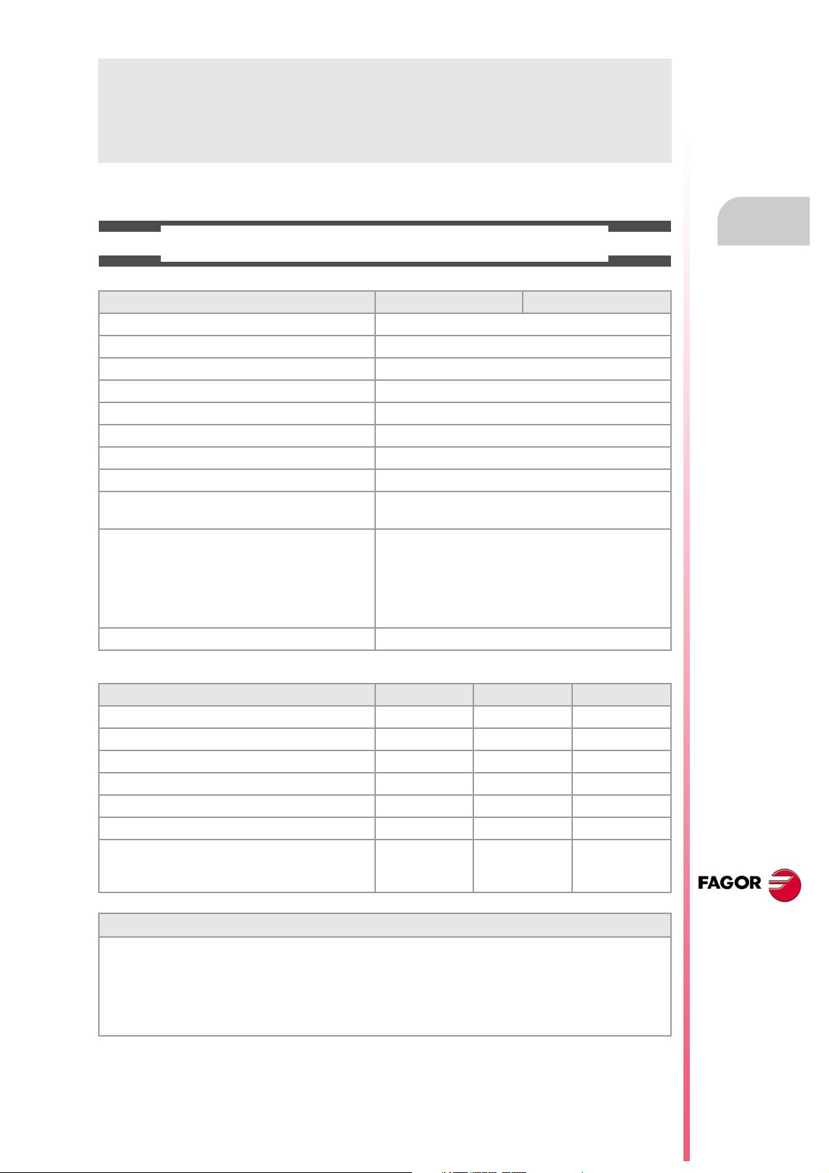
BASIC CHARACTERISTICS.
Basic characteristics. ·M· ·T·
PC-based system. Open system
Operating system. Windows XP
Number of axes. 3 to 28
Number of spindles. 1 to 4
Number of tool magazines. 1 to 4
Number of execution channels. 1 to 4
Number of handwheels. 1 to 12
Type of servo system. Analog / Digital Sercos / Digital Mechatrolink
Communications. RS485 / RS422 / RS232
Ethernet
Integrated PLC.
PLC execution time.
Digital inputs / Digital outputs.
Marks / Registers.
Timers / Counters.
Symbols.
Block processing time. < 1 ms
< 1ms/K
1024 / 1024
8192 / 1024
512 / 256
Unlimited
Remote modules. RIOW RIO5 RIO70
Communication with the remote modules. CANopen CANopen CANfagor
Digital inputs per module. 8 16 or 32 16
Digital outputs per module. 8 24 or 48 16
Analog inputs per module. 4 4 8
Analog outputs per module. 4 4 4
Inputs for PT100 temperature sensors. 2 2 - - -
Feedback inputs. - - - - - - 4
Differential TTL
Sinusoidal 1 Vpp
Customizing.
PC-based open system, fully customizable.
INI configuration files.
FGUIM visual configuration tool.
Visual Basic®, Visual C++®, etc.
Internal databases in Microsoft® Access.
OPC compatible interface
CNC 8065
(REF: 1309)
·5·
Page 6
Probing (·T· model)
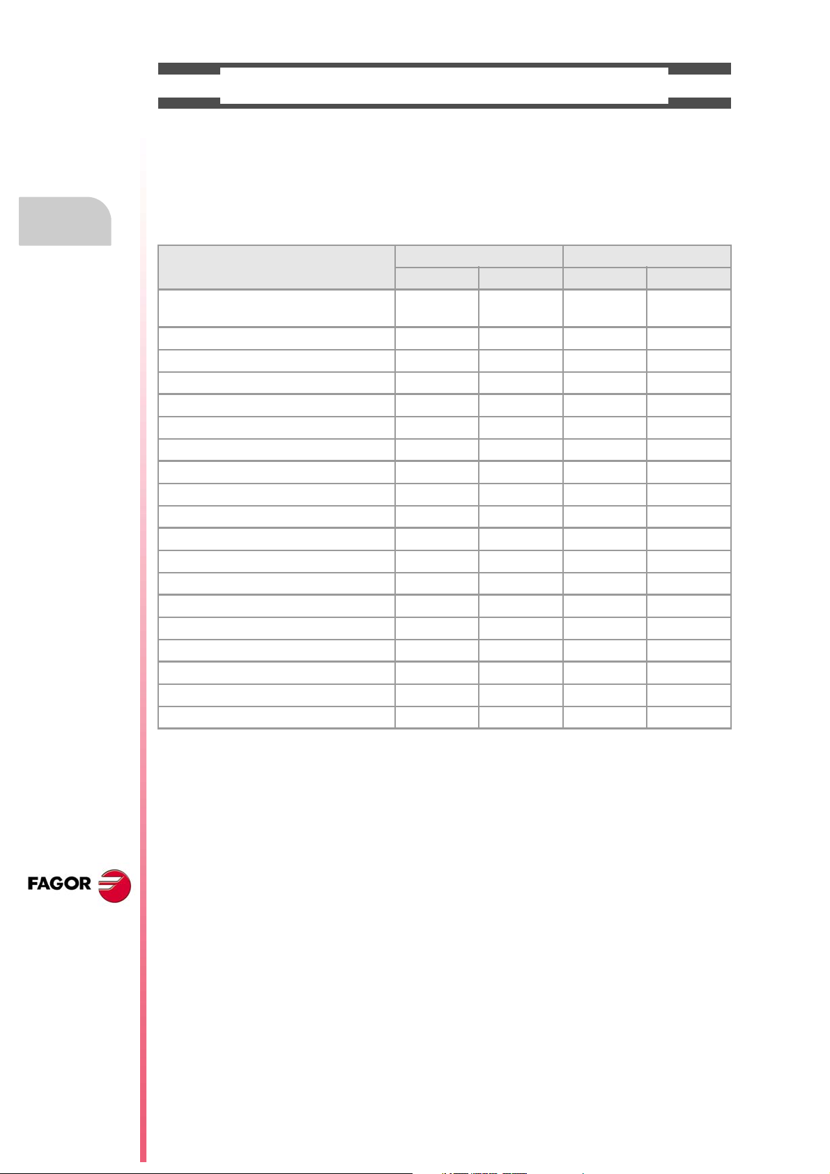
SOFTWARE OPTIONS.
Bear in mind that some of the features described in this manual depend on the software options that are
installed. The information of the following table is informative only; when purchasing the software options,
only the information provided in the ordering handbook is valid.
Software options (·M· model).
8065 M 8065 M Power
Basic Pack 1 Basic Pack 1
Open system.
Access to the administrator mode.
Number of execution channels 1 1 1 1 to 4
Number of axes 3 to 6 5 to 8 5 to 12 8 to 28
Number of spindles 1 1 1 to 4 1 to 4
Number of tool magazines 1 1 1 1 to 4
Limited to 4 interpolated axes Option Option Option Option
IEC 61131 language - - - - - - Option Option
HD graphics Option Option Standard Standard
Conversational IIP Option Option Option Option
Dual-purpose machines (M-T) - - - - - - Option Standard
"C" axis Standard Standard Standard Standard
Dynamic RTCP - - - Option Option Standard
HSSA machining system. Standard Standard Standard Standard
Probing canned cycles Option Standard Standard Standard
Tandem axes - - - Option Standard Standard
Synchronism and cams - - - - - - Option Standard
Tangential control - - - Standard Standard Standard
Volumetric compensation (up to 10 m³). - - - - - - Option Option
Volumetric compensation (more than 10 m³). - - - - - - Option Option
- - - - - - Option Option
CNC 8065
(REF: 1309)
·6·
Page 7
Probing (·T· model)
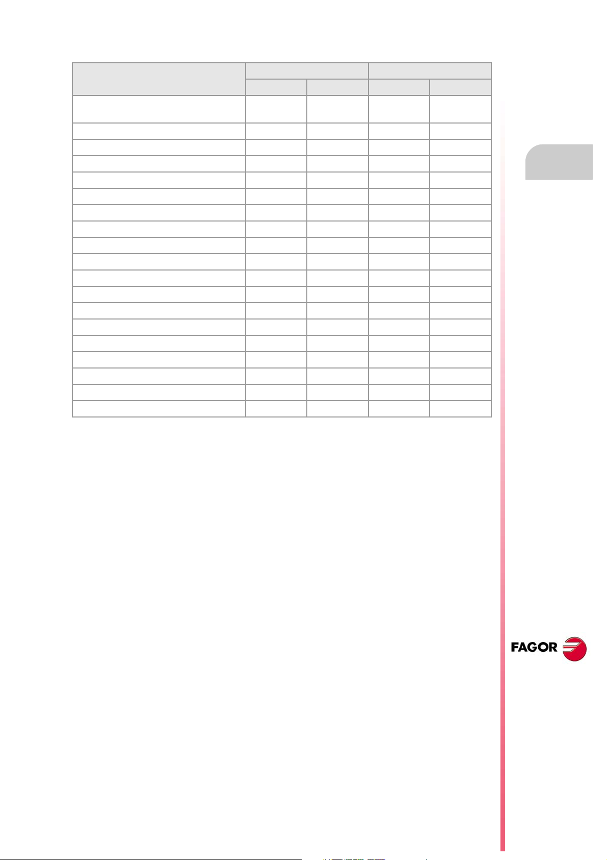
Software options (·T· model).
8065 T 8065 T Power
Basic Pack 1 Basic Pack 1
Open system.
Access to the administrator mode.
Number of execution channels 1 1 to 2 1 to 2 1 to 4
Number of axes 3 to 5 5 to 7 5 to 12 8 to 28
Number of spindles 2 2 3 to 4 3 to 4
Number of tool magazines 1 1 to 2 1 to 2 1 to 4
Limited to 4 interpolated axes Option Option Option Option
IEC 61131 language - - - - - - Option Option
HD graphics Option Option Standard Standard
Conversational IIP Option Option Option Option
Dual-purpose machines (T-M) - - - - - - Option Standard
"C" axis Option Standard Standard Standard
Dynamic RTCP - - - - - - Option Standard
HSSA machining system. Option Standard Standard Standard
Probing canned cycles Option Standard Standard Standard
Tandem axes - - - Option Standard Standard
Synchronism and cams - - - Option Option Standard
Tangential control - - - - - - Option Standard
Volumetric compensation (up to 10 m³). - - - - - - Option Option
Volumetric compensation (more than 10 m³). - - - - - - Option Option
- - - - - - Option Option
CNC 8065
(REF: 1309)
·7·
Page 8

Page 9
Probing (·T· model)
VERSION HISTORY
Here is a list of the features added to each manual reference.
Ref. 1103
First version.
Ref. 1309
Software V04.27
Executing G100/G103/G104 updates variables (V.)A.MEAS.Xn,
(V.)A.MEASOF.Xn and (V.)A.MEASOK.Xn of all the axes of the channel.
The variable keeps its value after a reset. • Variable: (V.)A.MEASOK.Xn
The CNC lets make a measurement (G100/G103/G104) on any axis of the
channel even when function G101 is active.
Measuring an axis does not change the G101 of the rest of the axes. • Function: G101.
The CNC lets program any axis of the channel in a G101 block even if it has
not been involved in the previous measurement (G100/G103/G104).
The CNC lets program any axis of the channel in a G102 block even if it does
not have a measuring offset included (G101).
• Variables: (V.)A.MEAS.Xn
(V.)A.MEASOF.Xn (V.)A.MEASOK.Xn
• Function: G101.
• Function: G101.
• Function: G102.
CNC 8065
(REF: 1309)
·9·
Page 10

Page 11
Probing (·T· model)
SAFETY CONDITIONS
Read the following safety measures in order to prevent harming people or damage to this product and those
products connected to it. Fagor Automation shall not be held responsible of any physical damage or
defective unit resulting from not complying with these basic safety regulations.
Before start-up, verify that the machine that integrates this CNC meets the 89/392/CEE Directive.
PRECAUTIONS BEFORE CLEANING THE UNIT
If the CNC does not turn on when actuating the start-up switch, verify the connections.
Do not get into the inside of the unit. Only personnel authorized by Fagor Automation may manipulate the
Do not handle the connectors with the unit
connected to AC power.
inside of this unit.
Before manipulating the connectors (inputs/outputs, feedback, etc.)
make sure that the unit is not connected to AC power.
PRECAUTIONS DURING REPAIR
In case of a malfunction or failure, disconnect it and call the technical service.
Do not get into the inside of the unit. Only personnel authorized by Fagor Automation may manipulate the
inside of this unit.
Do not handle the connectors with the unit
connected to AC power.
Before manipulating the connectors (inputs/outputs, feedback, etc.)
make sure that the unit is not connected to AC power.
PRECAUTIONS AGAINST PERSONAL DAMAGE
Interconnection of modules. Use the connection cables provided with the unit.
Use proper cables. To prevent risks, use the proper cables for mains, Sercos and Bus
CAN recommended for this unit.
In order to avoid electrical shock at the central unit, use the proper
power (mains) cable. Use 3-wire power cables (one for ground
connection).
Avoid electrical overloads. In order to avoid electrical discharges and fire hazards, do not apply
electrical voltage outside the range selected on the rear panel of the
central unit.
Ground connection. In order to avoid electrical discharges, connect the ground terminals
of all the modules to the main ground terminal. Before connecting the
inputs and outputs of this unit, make sure that all the grounding
connections are properly made.
In order to avoid electrical shock, before turning the unit on verify that
the ground connection is properly made.
Do not work in humid environments. In order to avoid electrical discharges, always work under 90% of
relative humidity (non-condensing) and 45 ºC (113 ºF).
Do not work in explosive environments. In order to avoid risks or damages, do no work in explosive
environments.
CNC 8065
(REF: 1309)
·11·
Page 12
Probing (·T· model)
PRECAUTIONS AGAINST PRODUCT DAMAGE
Working environment. This unit is ready to be used in industrial environments complying with
the directives and regulations effective in the European Community.
Fagor Automation shall not be held responsible for any damage
suffered or caused by the CNC when installed in other environments
(residential or homes).
Install the unit in the right place. It is recommended, whenever possible, to install the CNC away from
coolants, chemical product, blows, etc. that could damage it.
This unit complies with the European directives on electromagnetic
compatibility. Nevertheless, it is recommended to keep it away from
sources of electromagnetic disturbance such as:
Powerful loads connected to the same AC power line as this
equipment.
Nearby portable transmitters (Radio-telephones, Ham radio
transmitters).
Nearby radio/TV transmitters.
Nearby arc welding machines.
Nearby High Voltage power lines.
Enclosures. The manufacturer is responsible of assuring that the enclosure
involving the equipment meets all the currently effective directives of
the European Community.
Avoid disturbances coming from the
machine.
Use the proper power supply. Use an external regulated 24 Vdc power supply for the keyboard and
Grounding of the power supply. The zero volt point of the external power supply must be connected
Analog inputs and outputs connection. Use shielded cables connecting all their meshes to the corresponding
Ambient conditions. The storage temperature must be between +5 ºC and +45 ºC (41 ºF
Central unit enclosure. Make sure that the needed gap is kept between the central unit and
Main AC power switch. This switch must be easy to access a nd at a distance between 0.7 and
The machine must have all the interference generating elements
(relay coils, contactors, motors, etc.) uncoupled.
the remote modules.
to the main ground point of the machine.
pin.
and 113 ºF).
The storage temperature must be between -25 ºC and 70 ºC (-13 ºF
and 158 ºF).
each wall of the enclosure.
Use a DC fan to improve enclosure ventilation.
1.7 m (2.3 and 5.6 ft) off the floor.
CNC 8065
(REF: 1309)
·12·
PROTECTIONS OF THE UNIT ITSELF
Remote modules. All the digital inputs and outputs have galvanic isolation via
optocouplers between the CNC circuitry and the outside.
Page 13
Probing (·T· model)
i
SAFETY SYMBOLS
Symbols that may appear on the manual.
Danger or prohibition symbol.
It indicates actions or operations that may hurt people or damage products.
Warning symbol.
It indicates situations that certain operations could cause and the suggested actions to prevent them.
Obligation symbol.
It indicates actions and operations that must be carried out.
Information symbol.
It indicates notes, warnings and advises.
Symbols that the product may carry.
Ground protection symbol.
It indicates that that point must be under voltage.
CNC 8065
(REF: 1309)
·13·
Page 14

Page 15
Probing (·T· model)
WARRANTY TERMS
INITIAL WARRANTY
All products manufactured or marketed by FAGOR carry a 12-month warranty for the end user which could
be controlled by the our service network by means of the warranty control system established by FAGOR
for this purpose.
In order to prevent the possibility of having the time period from the time a product leaves our warehouse
until the end user actually receives it run against this 12-month warranty, FAGOR has set up a warranty
control system based on having the manufacturer or agent inform FAGOR of the destination, identification
and on-machine installation date, by filling out the document accompanying each FAGOR product in the
warranty envelope. This system, besides assuring a full year of warranty to the end user, enables our service
network to know about FAGOR equipment coming from other countries into their area of responsibility.
The warranty starting date will be the one appearing as the installation date on the above mentioned
document. FAGOR offers the manufacturer or agent 12 months to sell and install the product. This means
that the warranty starting date may be up to one year after the product has left our warehouse so long as
the warranty control sheet has been sent back to us. This translates into the extension of warranty period
to two years since the product left our warehouse. If this sheet has not been sent to us, the warranty period
ends 15 months from when the product left our warehouse.
This warranty covers all costs of material and labour involved in repairs at FAGOR carried out to correct
malfunctions in the equipment. FAGOR under takes to repair or replace their products within the period from
the moment manufacture begins until 8 years after the date on which it disappears from the catalogue.
It is entirely up to FAGOR to determine whether the repair is or not under warranty.
EXCLUDING CLAUSES
Repairs will be carried out on our premises. Therefore, all expenses incurred as a result of trips made by
technical personnel to carry out equipment repairs, despite these being within the above-mentioned period
of warranty, are not covered by the warranty.
Said warranty will be applied whenever the equipment has been installed in accordance with instructions,
has not be mistreated, has not been damaged by accident or by negligence and has not been tampered
with by personnel not authorised by FAGOR. If, once servicing or repairs have been made, the cause of
the malfunction cannot be attributed to said elements, the customer is obliged to cover the expenses
incurred, in accordance with the tariffs in force.
Other warranties, implicit or explicit, are not covered and FAGOR AUTOMATION cannot be held responsible
for other damages which may occur.
CNC 8065
(REF: 1309)
·15·
Page 16
Probing (·T· model)
WARRANTY ON REPAIRS
In a similar way to the initial warranty, FAGOR offers a warranty on standard repairs according to the
following conditions:
PERIOD 12 months.
CONCEPT Covers parts and labor for repairs (or replacements) at the
network's own facilities.
EXCLUDING CLAUSES The same as those applied regarding the chapter on initial
warranty. If the repair is carried out within the warranty period, the
warranty extension has no effect.
When the customer does not choose the standard repair and just the faulty material has been replaced,
the warranty will cover just the replaced parts or components within 12 months.
For sold parts the warranty is 12 moths length.
SERVICE CONTRACTS
The SERVICE CONTRACT is available for the distributor or manufacturer who buys and installs our CNC
systems.
CNC 8065
(REF: 1309)
·16·
Page 17
Probing (·T· model)
MATERIAL RETURNING TERMS
When sending the central nit or the remote modules, pack them in its original package and packaging
material. If the original packaging material is not available, pack it as follows:
1 Get a cardboard box whose three inside dimensions are at least 15 cm (6 inches) larger than those
of the unit. The cardboard being used to make the box must have a resistance of 170 Kg (375 lb.).
2 Attach a label indicating the owner of the unit, person to contact, type of unit and serial number. In case
of malfunction also indicate symptom and a brief description of the problem.
3 Wrap the unit in a polyethylene roll or similar material to protect it. When sending a central unit with
monitor, protect especially the screen.
4 Pad the unit inside the cardboard box with poly-utherane foam on all sides.
5 Seal the cardboard box with packing tape or industrial staples.
CNC 8065
(REF: 1309)
·17·
Page 18

Page 19
Probing (·T· model)
CNC MAINTENANCE
CLEANING
The accumulated dirt inside the unit may act as a screen preventing the proper dissipation of the heat
generated by the internal circuitry which could result in a harmful overheating of the unit and, consequently,
possible malfunctions. Accumulated dirt can sometimes act as an electrical conductor and short-circuit the
internal circuitry, especially under high humidity conditions.
To clean the operator panel and the monitor, a smooth cloth should be used which has been dipped into
de-ionized water and /or non abrasive dish-washer soap (liquid, never powder) or 75º alcohol. Do not use
highly compressed air to clean the unit because it could generate electrostatic discharges.
The plastics used on the front panel are resistant to grease and mineral oils, bases and bleach, dissolved
detergents and alcohol. Avoid the action of solvents such as chlorine hydrocarbons, venzole, esters and
ether which can damage the plastics used to make the unit’s front panel.
PRECAUTIONS BEFORE CLEANING THE UNIT
Fagor Automation shall not be held responsible for any material or physical damage derived from the
violation of these basic safety requirements.
• Do not handle the connectors with the unit connected to AC power. Before handling these connectors
(I/O, feedback, etc.), make sure that the unit is not connected to main AC power.
• Do not get into the inside of the unit. Only personnel authorized by Fagor Automation may manipulate
the inside of this unit.
• If the CNC does not turn on when actuating the start-up switch, verify the connections.
CNC 8065
(REF: 1309)
·19·
Page 20

Page 21
PREVIOUS NOTIONS ABOUT THE PROBE.
Number of probes in the system and active probe.
The CNC may have configured two probes, it will usually be a tabletop probe to calibrate tools
and a touch probe to measure the part.
Before any probing moves, select the probe to be used. See "1.1 Activate the probe." on
page 22.
Probe operation.
Both probes operate by levels, not by flanks.
Probing.
1
With function G100, it is possible to program movements that will end when the CNC receives
the probe signal (when the probe makes contact). When done probing, the CNC updates
the real coordinates.
With function G103, it is possible to program movements that will end when the CNC stops
receiving the probe signal (when the probe no longer makes contact). When done probing,
the CNC updates the real coordinates.
The G104 function prevents a G100 or G103 probe movement from finishing with the probe
signal The CNC updates the coordinates with the probe signal, but without interrupting the
movement which continues until the probe reaches the programmed position.
Programming the canned cycles.
The probing canned cycles may be edited in ISO code or with using the cycle editor. These
cycles may be defined anywhere in the program, that is, in the main program as well as in
a subroutine. ISO coded cycles can also be executed in MDI.
Probe parameter setting.
The machine manufacturer must have properly set the following machine parameters.
• General machine parameters.
PROBE PROBEDATA PROBETYPE1 PROBETYPE2
PRBDI1 PRBDI2 PRBPULSE1 PRBPULSE2
• General machine parameters per channel.
PROBEDATA PRB1MAX PRB1MIN PRB2MAX
PRB2MIN PRB3MAX PRB3MIN
• Axis machine parameters.
PROBEAXIS PROBERANGE PROBEFEED PROBEDELAY
PROBEDELAY2
CNC 8065
(REF: 1309)
·21·
Page 22
1.1 Activate the probe.
The CNC can have configured two probes. Before any probing move, the CNC must know
which is the active probe, or, which is the same, which of the two probes it must attend to.
It is selected via part-program or MDI using the instruction #SELECT PROBE.
If a probing move is executed without activating the probe, it will not send any signal to the CNC when
it makes contact. This can cause the probe to break because the probing move will not be stopped.
Probing (·T· model)
1.
Activate the probe.
PREVIOUS NOTIONS ABOUT THE PROBE.
Programming.
When programming this instruction, you must define which probe is active and whether it's
active high or low.
Programming format.
The programming format is the following; the list of arguments appears between curly
brackets and the optional ones between angle brackets.
#SELECT PROBE [<{probe}><, {pulse}>]
{probe} Optional. Number of probe to activate.
If not programmed, the CNC uses the active probe.
{pulse} Optional. Logic level to activate probe. The CNC uses the high level with
"POS" and the low level with "NEG".
If not programmed, the CNC uses the default probe activation level.
Although both parameters are optional, at least one of them must be programmed.
#SELECT PROBE [1]
#SELECT PROBE [NEG]
#SELECT PROBE [2, POS]
#SELECT PROBE [1, NEG]
Probe number. Which is probe 1 and which probe 2?
CNC 8065
(REF: 1309)
The names of the probes are set in the order they have been defined in the machine
parameters. The CNC assumes as first probe the one connected to the input indicated in
machine parameter PRBDI1 and as second probe the one connected to the input indicated
in machine parameter PRBDI2.
Logic level to activate probe; high (5 V / 24 V) or low (0 V).
Changing the default activation level reverses the operation of functions G100 and G103.
When changing the probe logic activation level, G100 makes a movement until the probe
stops making contact and G103 makes a movement until the probe makes contact. Since
probing canned cycles use functions G100 and G103, changing the logic activation level also
changes the operation of the canned cycles accordingly.
The logic activation level indicates whether the probe operations are active high (24V or 5
V) or active low (0V) of the signal provided by the probe. Programming the logic activation
level is optional because each probe has been assigned one by default.
The logic activation level of each probe by default is set in the machine parameters
(parameters PRBPULSE1 for probe ·1· and PRBPULSE2 for probe ·2·) and it depends on
the connection between the probe and the CNC.
Properties of the instruction and influence of reset, turning the
CNC off and of the M30 function.
The instruction #SELECT PROBE is modal. The probe and the selected logic activation level
stays active after an M02 or M30 and after an error or a reset. On power-up and after
validating the machine parameters, the CNC activates probe ·1· and initializes the logic
activation level of both probes with the values set in the machine parameters.
·22·
Page 23
Probing (·T· model)
Knowing which is the active probe.
The CNC offers the following variable to know which is the active probe. The variable can
only be read via part-program, MDI, PLC and interface.
Variab le. Meaning.
(V.)[ch].G.ACTIVPROBE This variable indicates which one is the active probe in channel n.
1.
Activate the probe.
PREVIOUS NOTIONS ABOUT THE PROBE.
CNC 8065
(REF: 1309)
·23·
Page 24
1.
X+
Z+
Y+
X+
Z+
Probing (·T· model)
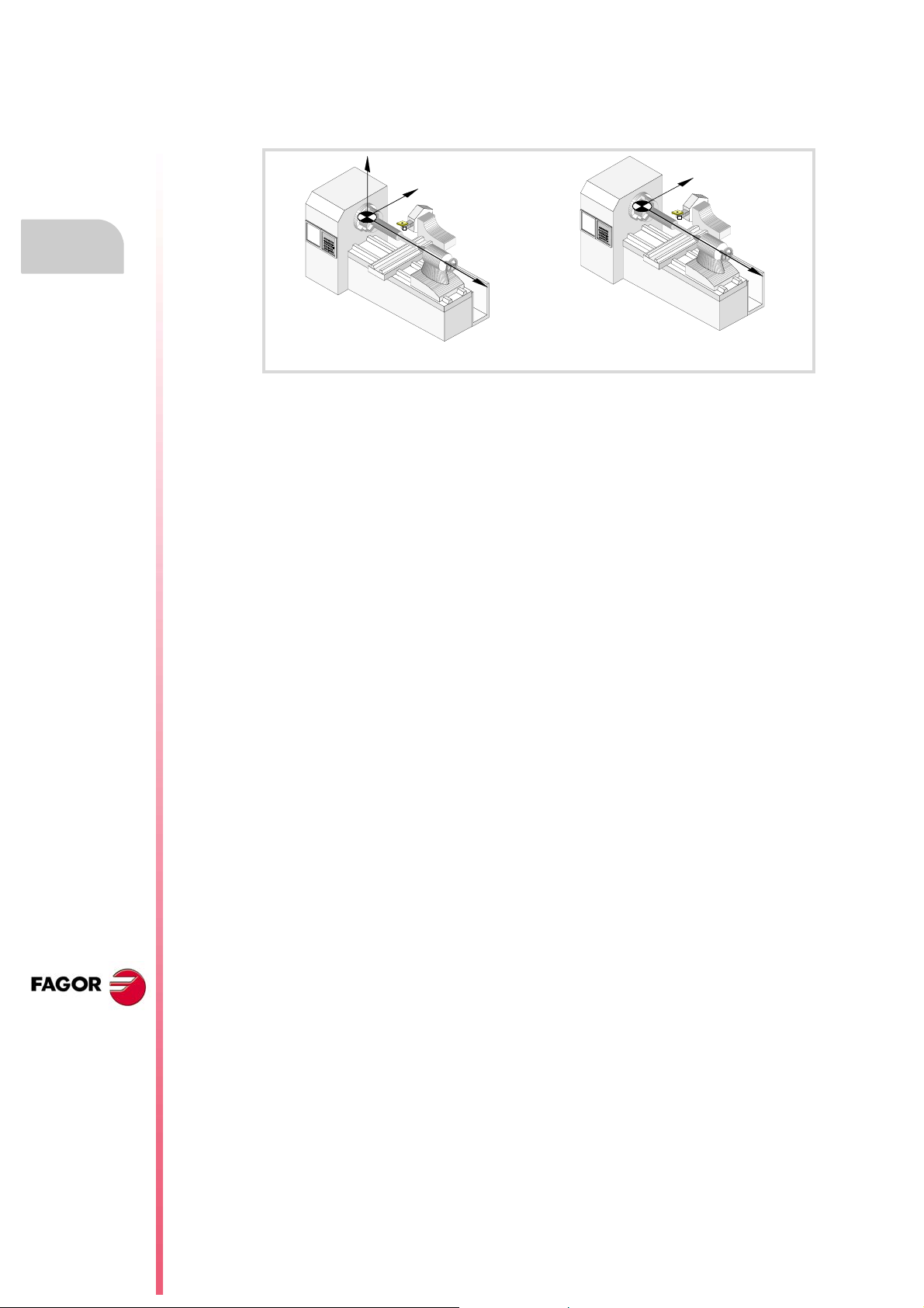
1.2 Geometric configuration of axes and work planes.
The CNC admits two types of geometric configurations; "Trihedron" type and "Plane" type
axis configuration.
Trihedron Plane
Configuration of "Trihedron" type axes.
In this configuration, there are three axes forming a Cartesian XYZ type trihedron like on a
milling machine. There may be more axes besides those forming the trihedron.
PREVIOUS NOTIONS ABOUT THE PROBE.
Geometric configuration of axes and work planes.
With this configuration, the planes behave in the same way as on a milling machine except
that the usual work plane will be G18 (if it has been configured like that).
All the movements of these cycles are executed on the X Y Z axes; the work plane must be
formed by 2 of these axes (XY, XZ, YZ, YX, ZX, ZY). The other axis, that must be
perpendicular to that plane must be selected as axis perpendicular to the work plane.
Configuration of "plane" type axes.
In this configuration, there are two axes forming the usual work plane. There may be more
axes, but they cannot be part of the trihedron; there must be auxiliary, rotary, etc.
With this configuration, the work plane is always G18 and will be formed by the first two axes
defined in the channel. If the X (first) and Z (second) axes have been defined, the work plane
will be the ZX (Z as abscissa and X as ordinate).
The probing movements can only be executed in the work plane. The CNC ignores the
programmed variables that are related to the axis perpendicular to the work plane.
Configuration of "plane" type axes. Plane selection.
The work plane is always G18; machine parameter IPLANE is not applied and it is not
possible to change planes via part-program. The following functions have these effects:
G17 It does not change planes and shows a warning about it.
G18 It has no effect.
G19 It does not change planes and shows a warning about it.
G20 It is permitted if it does not change the main plane; i.e. it can only be used to
change the longitudinal axis.
CNC 8065
(REF: 1309)
·24·
The ·G· functions associated with the work planes are not displayed because it is always the
same plane.
Page 25

Probing (·T· model)
1.3 Behavior of the feedrate in probing movements.
The probing moves are carried out at the active feedrate, the one defined for machining. If
the probing feedrate is changed, the new feedrate will be the active one for the machining
moves.
The feedrate may be selected by programmed using the "F" code which remains active until
another value is programmed. In the canned cycles, the feedrate may be programmed inside
the parameters of the cycle.
The units depend on the active work mode; G93, G94 or G95.
G93 Machining time in seconds.
G94 Feedrate in millimeters/minute (inches/minute).
G95 Feedrate in millimeters/revolution (inches/revolution).
The active feedrate may be varied between 0% and 200% using the selector switch on the
CNC's operator panel or it may be selected by program or by PLC.
Maximum probing feedrate.
The maximum probing feedrate in each axis will be limited by machine parameter
PROBEFEED and this value will not be exceeded even when programming a higher value.
1.
PREVIOUS NOTIONS ABOUT THE PROBE.
Behavior of the feedrate in probing movements.
CNC 8065
(REF: 1309)
·25·
Page 26

1.
Probing (·T· model)
PREVIOUS NOTIONS ABOUT THE PROBE.
Behavior of the feedrate in probing movements.
CNC 8065
(REF: 1309)
·26·
Page 27

PROBING.
2.1 G100/G103. Probing.
With function G100, it is possible to program movements that will end when the CNC receives
the probe signal (when the probe makes contact) or when the probe reaches the
programmed position. When done probing, the CNC assumes as the theoretical position the
current position of the axes involved in the movement, their real (actual) position at that
instant.
With function G103, it is possible to program movements that will end when the CNC stops
receiving the probe signal (when the probe stops making contact) or when the probe reaches
the programmed position. When done probing, the CNC assumes as the theoretical position
the current position of the axes involved in the movement, their real (actual) position at that
instant.
Functions G100 and G103 do not execute the tool change to select the probe, the probe must
be selected in a previous block of the program. Likewise, when using more than one probe,
the probe to be used must be selected before probing.
2
Probing programming.
The probing movement is defined using function G100 or G103 followed by the coordinates
of the probe's target point. Programming the feedrate is optional; if not programmed, these
movements are carried out at the active feedrate.
Programming format.
The programming format is: Optional parameters are indicated between angle brackets.
G100 X..C <F>
G103 X..C <F>
X..C Coordinates of the probing point.
F Optional. Feedrate.
If not programmed, the CNC uses the active feedrate.
G100 X45.23 Z23.45
G100 Z50 F100
G103 X2.6 Z3 F20
G103 Z1 F20
Probing feedrate.
The CNC uses the same feedrate for probing and for machining. The feedrate "F" set for the
probe will be the feedrate active at the CNC when done probing.
CNC 8065
The maximum probing feedrate in each axis will be limited by machine parameter
PROBEFEED and this value will not be exceeded even when programming a higher value
or exceeded with the switch on the operator panel.
The active feedrate may be varied between 0% and 200% using the selector switch on the
CNC's operator panel or it may be selected by program or by PLC.
(REF: 1309)
·27·
Page 28

2.
PROBING.
G100/G103. Probing.
Probing (·T· model)
Properties of the function and Influence of the reset, turning the
CNC off and of the M30 function.
Functions G100 and G103 are not modal. After executing one of these functions, the CNC
restores the function G0, G1, G2 ó G3, G33 or G63 that was active.
CNC 8065
(REF: 1309)
Updating variables after probing.
When done probing, the CNC updates the following variables. After a probing, the CNC
updates all the variables of all the axes of the channel even if they were not involved in the
probing movements. For the axes not involved in the probing movements, the variables that
save the measured value take the value of the real position of the axis and the variables that
indicate the measured error are reset to zero.
Mnemoni. Variabl e.
V.G.MEASOK The probe has made contact (G100) or stopped making contact (G103).
• The variable takes the value of ·1· if the probe has made contact (G100)
or has stopped making contact (G103).
• The variables takes the value of ·0· if the probe reaches the programmed
coordinate.
V.A.MEASOK.xn Probing done on any axis of the channel.
• The variables of the axes involved in the probing operation take the value
of ·1· when the probing movement ends.
• The variables of the rest of the axes take the value of ·0·.
The variable keeps its value after a reset.
V.G.PLMEASOK1
V.G.PLMEASOK2
V.G.PLMEASOK3
V.A.MEAS.xn Measured value. Machine coordinates of the tool base.
V.A.ATIPMEAS.xn Measured value. Part coordinates of the tool tip.
V.G.PLMEAS1
V.G.PLMEAS2
V.G.PLMEAS3
Probing on the plane axes completed.
• The variables of the axes involved in the probing operation take the value
of ·1· when the probing operation ends.
• The variables of the rest of the axes take the value of ·0·.
• The variables of the axes involved in the probing operation take the
measured value.
• The variables of the rest of the axes take the real position value of the
axis.
• The variables of the axes involved in the probing operation take the
measured value.
• The variables of the rest of the axes take the real position value of the
axis.
Value measured on the axes of the plane. Part coordinates of the tool tip.
• The variables of the axes involved in the probing operation take the
measured value.
• The variables of the rest of the axes take the real position value of the
axis.
·28·
Page 29

Probing (·T· model)
Mnemoni. Varia ble .
V.A.MEASOF.xn Measuring error.
• The variables of the axes involved in the probing operation take the
measuring error (difference between the programmed coordinate and
the one measured).
• The variables of the rest of the axes take the value of ·0·.
2.
PROBING.
G100/G103. Probing.
CNC 8065
(REF: 1309)
·29·
Page 30

2.
PROBING.
Probing (·T· model)
2.2 G101/G102. Include/exclude the measuring error in the theoretical coordinate.
The measuring error is the difference between the programmed coordinate and the
coordinate reached by the probe. The measuring error is given in the active units, radius or
diameter.
coordinate.
After probing, the CNC assumes the current axis position as the theoretical position.
Functions G101 and G102 determine whether to consider or ignore the measuring error
when updating the theoretical coordinate.
G101 Include the measuring error in the theoretical coordinate.
G102 Exclude the measuring error in the theoretical coordinate.
CNC 8065
Influence of the reset, turning the CNC off and of the M30.
Functions G101 and G102 are modal and incompatible with each other. On power-up, after
G101/G102. Include/exclude the measuring error in the theoretical
an M02 or M30 and after an EMERGENCY or a RESET, the CNC maintains the values
programmed with G101.
G101 Include the measuring error in the theoretical
coordinate.
When executing this function, the CNC includes the error resulting from the measurement
to set the theoretical axis positions; in other words, the CNC will assume as theoretical axis
position the programmed coordinate (position reached by the probe + the measuring error).
Function G101 must be executed after taking a measurement. The CNC lets program any
axis of the channel in a G101 block even if it has not been involved in the previous
measurement (G100/G103/G104).
The CNC lets make a measurement (G100/G103/G104) on any axis of the channel even
when function G101 is active. The measurement on an axis does not change the G101 of
other axes and, therefore, it does not change its variable (V.)A.MEASIN.xn.
Programming format.
To include the measuring error, program function G101 and then the axes in which to include
the measuring error. For each axis, you must define how many times the measuring error
is added to the coordinate. Usually, the measuring error needs to be included only once.
G101 X..C
X..C Axes whose theoretical coordinate includes the measuring error .
(REF: 1309)
·30·
G101 X1 Z1
G101 X2
Page 31

Probing (·T· model)
Updating the variables after executing function G101.
Variab le Valu e
(V.)[n].A.MEASOF.Xn It is initialized to 0 (zero).
(V.)[n].A.MEASIN.Xn Measuring error added to the Xn axis.
2.
PROBING.
coordinate.
G101/G102. Include/exclude the measuring error in the theoretical
CNC 8065
(REF: 1309)
·31·
Page 32

2.
PROBING.
coordinate.
Probing (·T· model)
G102 Exclude the measuring error in the theoretical
coordinate.
After executing this function, the CNC will ignore the error resulting from the measurement
to set the theoretical position of the axes; i.e. the CNC considers the coordinate reached as
theoretical coordinate.
The CNC lets program any axis of the channel in a G102 block even if it does not have a
measuring offset included (G101).
Programming format.
To ignore the measuring error, program function G102 and then the axes in which to ignore
it. If no axis is programmed, the CNC ignores the measuring error in all the axes.
The programming format is: Optional parameters are indicated between angle brackets.
G102 <X..C>
X..C Optional. Axes whose theoretical coordinate does not include the measuring error
.
G102 X Z
G102
Once function G102 is executed, function G101 cannot be executed again until a new
measurement is taken.
Updating the variables after executing function G102.
Variable Valu e
(V.)[n].A.MEASIN.Xn It is initialized to 0 (zero).
G101/G102. Include/exclude the measuring error in the theoretical
CNC 8065
(REF: 1309)
·32·
Page 33

Probing (·T· model)
2.3 G104. Probe movement up to the programmed position.
When programming function G104 together with G100 or G103, the CNC makes the selected
probing movement, updates the coordinates when it receives the probe signal, but keeps
moving the axes until they reach their programmed position.
Function G101 may be used to make the CNC assume the measuring error resulting from
a G104 movement,
Probing programming.
The G104 must be programmed together with a G100 or G103 probe movement; otherwise,
it will be ignored.
Programming format.
The programming format is: Optional parameters are indicated between angle brackets.
G100 G104 X..C <F>
G103 G104 X..C <F>
X..C Coordinates of the probing point.
F Optional. Feedrate.
If not programmed, the CNC uses the active feedrate.
G100 G104 Z23.45
G103 G104 Z1 F20
Properties of the function and Influence of the reset, turning the
CNC off and of the M30 function.
Function G104 is not modal; it only acts in the block where it is programmed.
2.
PROBING.
G104. Probe movement up to the programmed position.
CNC 8065
(REF: 1309)
·33·
Page 34

2.
PROBING.
Properties of measurement related variables.
Probing (·T· model)
2.4 Properties of measurement related variables.
For further information about the access and the use of variables, refer to the programming manual.
The following variables are read-only (R) synchronous and are evaluated while in execution.
The mnemonics of the variables have generic names.
• Replace the "Xn" character by the name, logic number or index in the channel of the axis.
• Replace the "n" character with the channel number, maintaining the brackets. The first
channel is identified with the number 1, "0" is not a valid number.
Mnemonic PRG PLC INT
(V.)[n].A.MEASOK.Xn R R R Probing done on the Xn axis.
"0" = No "1"= Yes
(V.)[n].G.PLMEASOK1 R — — Probing done on the first axis of the plane.
"0" = No "1"= Yes
(V.)[n].G.PLMEASOK2 R — — Probing done on the second axis of the plane.
"0" = No "1"= Yes
(V.)[n].G.PLMEASOK3 R — — Probing done on the axis perpendicular to the
plane.
"0" = No "1"= Yes
(V.)[n].A.MEAS.Xn R R R Value measured on the Xn axis.
Machine coordinates of the tool base.
(V.)[n].A.ATIPMEAS.Xn R — — Value measured on the Xn axis.
Part coordinates of the tool tip.
(V.)[n].G.PLMEAS1 R — — Value measure d on the f irst axi s of the pla ne
(abscissa).
Part coordinates of the tool tip.
(V.)[n].G.PLMEAS2 R — — Value measured on the second axis of the plane
(ordinate).
Part coordinates of the tool tip.
(V.)[n].G.PLMEAS3 R — — Value measured on the axis perpendicular to the
plane.
Part coordinates of the tool tip.
(V.)[n].A.MEASOF.Xn R R R Me a su r i ng e r ror. D i f fe ren c e be t w ee n t h e
programmed coordinate and the value measured
on the Xn axis.
(V.)[n].A.MEASIN.Xn R R R Measuring error added to the Xn axis.
CNC 8065
(REF: 1309)
·34·
Page 35

CANNED CYCLES. ISO CODED PROGRAMMING.
Canned cycles may be edited in ISO code (described in this chapter) or with using the cycle
editor. See chapter "4 Canned cycles. Cycle editor.".
The cycles may be defined anywhere in the program, that is, in the main program as well
as in a subroutine. ISO coded cycles can also be executed via MDI mode.
Programming ISO coded cycles.
ISO coded cycles are defined with the #PROBE instruction followed by the number of the
cycle to be executed and the call parameters.
#PROBE 1
#PROBE 2
#PROBE 3
#PROBE 4
Tool calibration.
Tabletop probe calibration
Part measuring along the ordinate axis.
Part measuring along the abscissa axis.
3
Probing canned cycles are not modal; therefore, they must be programmed every time any
of them is to be executed. The execution of these cycles does not change the program history.
Cycle data programming.
The cycle number and the rest of parameters may be defined with a number, an arithmetic
parameter or expression whose result is a number.
#PROBE 4 X10 Z20 B5 F10
P1=4 P2=10
#PROBE P1 XP2 Z[P2*2] B5 FP2
When using global parameters, bear in mind that some cycles modify the value of these
parameters at the end of the execution. Refer to each cycle to see which parameters it
modifies.
Limitations for executing the cycles.
These cycles cannot be executed if tool radius compensation is active.
Canned cycles and the work planes.
A canned cycle may be defined anywhere in the program, that is, in the main program as
well as in a subroutine. When working in a plane other than the ZX, the CNC interprets the
canned cycle parameters as follows:
CNC 8065
Parameter Z-X plane W-X plane A-B plane
Parameter Z and all related to it, with the abscissa
axis
Parameter X and all related to it, with the ordinate
axis
Z axis W axis A axis
X axis X axis B axis
(REF: 1309)
·35·
Page 36

3.
Probing (·T· model)
Combined (dual-purpose) machines Milling and turning canned
cycles available at the same CNC.
On dual-purpose machines, those where milling and turning operations may be carried out,
the CNC offers the possibility to run canned cycles of both machines. Since both types of
canned cycles share the same #PROBE instructions, the user can select which cycles to
execute. By default, it executes the cycles of the software installed.
On a mill model CNC (milling software installed).
By default, it will execute the milling canned cycles. To execute the turning canned cycles,
use the following instructions:
#LATHECY ON - To activate the turning canned cycles.
#LATHECY OFF - To deactivate the turning canned cycles.
On a lathe model CNC (lathe software installed).
By default, it will execute the turning canned cycles. To execute the milling canned cycles,
use the following instructions:
#MILLCY ON - To activate the milling canned cycles.
#MILLCY OFF - To deactivate the milling canned cycles.
CANNED CYCLES. ISO CODED PROGRAMMING.
CNC 8065
(REF: 1309)
·36·
Page 37

Probing (·T· model)
3.1 #PROBE 1. Tool calibration.
This cycle may be used to calibrate the dimensions of a tool or a touch probe. Once the cycle
has concluded, it updates the dimensions in the tool table and initializes the tool wears to
0 (zero).
The calibration is done using a tabletop probe.
The cycle calibrates the active tool. The tool must be selected at the CNC before executing
the cycle.
Requirements prior to the calibration.
If it is the first time the tool or the probe is being calibrated, enter in the tool table an
approximate dimensions, location code and the radius value. If it is a probe, the "R" value
will correspond to the radius of the probe ball and the location code will depend on how it
has been calibrated.
3.
#PROBE 1. Tool calibration.
Tabletop probe.
Executing this cycle requires a table-top probe, installed in a fixed position of the machine
and with its sides parallel to the axes of the plane. The probe position must be given in
absolute coordinates referred to machine reference zero using the machine parameters
PRB1MIN, PRB1MAX, PRB2MIN, PRB2MAX, PRB3MIN, PRB3MAX.
CANNED CYCLES. ISO CODED PROGRAMMING.
CNC 8065
(REF: 1309)
·37·
Page 38

3.
Probing (·T· model)
Data returned by the cycle after the measurement.
Once the cycle is over, the CNC will return the detected error in the following arithmetic
parameters. A detected error is the difference between the real tool length and the value
assigned in the table.
P298 Error detected along the abscissa axis.
This value is given in radius.
P299 Error detected along the ordinate axis.
P297 Error detected on the axis perpendicular to the plane.
This value is given in radius.
Once the cycle has concluded, it updates the dimensions in the tool table and initializes the
tool wears to 0 (zero).
#PROBE 1. Tool calibration.
CANNED CYCLES. ISO CODED PROGRAMMING.
CNC 8065
(REF: 1309)
·38·
Page 39

Probing (·T· model)
3.1.1 Programming the cycle.
The programming format for this cycle is. Optional parameters are indicated between angle
brackets.
#PROBE 1 B F <K> <X U Z W Y V>
B
F
K
X··W
·B· Safety distance.
This parameter only admits positive values greater than 0 (zero). Value defined in radius.
Distance with respect to the point to touch, to which the tool approaches in G00 before
making the probing movement. When calling the cycle, the tool must be located, with respect
to the point to be measured, at a greater distance than this value
·F· Probing feedrate.
This parameter sets the probing feedrate. The rest of the movements will be carried out in
G00.
·K· Sides of the probe to be used.
Safety distance.
Probing feedrate.
Optional. Sides of the probe to be used.
Optional. Tabletop probe position.
3.
#PROBE 1. Tool calibration.
Optional parameter, by default 0.
This parameter indicates how many sides of the probe will be used for calibration. In a "Plane"
type of axis configuration, two sides of the probe will always be used. In a "Trihedron" type
of axis configuration, it is possible to choose to use either two or three sides of the probe.
K=0 Calibration on the X, Z sides.
K=1 Calibration on the X, Z, Y+ sides.
K=2 Calibration on the X, Z, Y- sides.
·X U Y V Z W· Tabletop probe position.
They are optional parameters that usually need not be defined. In certain machines, due to
lack of repeatability in the mechanical positioning of the probe, the probe must be calibrated
again before each calibration. Instead of re-defining the machine parameters every time the
probe is calibrated, those coordinates may be indicated in these parameters.
Parameters X Z Y refer to the minimum coordinates of the probe on the first axis, second
axis and on the axis perpendicular to the plane respectively. Parameters U W V refer to the
maximum coordinates of the probe on the first axis, second axis and on the axis
perpendicular to the plane respectively.
This data does not modify the machine parameters. The CNC takes this data into account
only during this calibration. If any of this data is left out, the CNC takes the value assigned
to the corresponding machine parameter.
CANNED CYCLES. ISO CODED PROGRAMMING.
CNC 8065
(REF: 1309)
·39·
Page 40

3.
Probing (·T· model)
3.1.2 Basic operation.
#PROBE 1. Tool calibration.
CANNED CYCLES. ISO CODED PROGRAMMING.
CNC 8065
(REF: 1309)
·40·
Page 41

Probing (·T· model)
1 Approach movement.
Rapid probe movement (G00) from the cycle calling point to the approach corner. This
point is located in front of the associated probe corner, at a ·B· distance from it.
This approach movement is made in two stages. It first moves along the Z axis and then
along the X axis.
2 Probing movement.
The sides of the probe used in this probing move as well as the path traveled by the tool
depend on the location code assigned to the selected tool. When having a "Trihedron"
type geometrical configuration and the ·K· parameter has been defined with a value other
than zero, it will execute an additional probing move on the Y axis.
Each probing move will consist of an approach move, a probing move per se and a
withdrawal move.
Approach movement. Rapid probe move (G00) to the approach point located in front of
the side to be probed at a ·B· distance from it.
Probing movement. Probing movement at the indicated feedrate (F) until the probe signal
is received. The maximum probing distance is ·2B·. If the CNC does not receive the probe
signal before reaching moving this probing distance, it stops the axes and displays the
relevant error message.
Withdrawal movement. Rapid probe movement (G00) from the probing point to the
approach corner.
3 Withdrawal movement.
Rapid probe movement (G00) from the approach corner to the cycle calling point.
This withdrawal movement is made in two stages. It first moves along the X axis and then
along the Z axis.
3.
#PROBE 1. Tool calibration.
CANNED CYCLES. ISO CODED PROGRAMMING.
CNC 8065
(REF: 1309)
·41·
Page 42

3.
Probing (·T· model)
3.2 #PROBE 2. Tabletop probe calibration
This cycle may be used calibrate the sides of the tabletop probe. Once the cycle has ended,
the user must enter the data returned by the cycle into the machine parameters that define
the position of the probe.
The calibration is carried out with a tool of known dimensions.
Requirements prior to the calibration.
To execute the cycle, use a master tool whose dimensions have already been defined in the
tool table. Since the probe needs to be calibrated along the X and Z axes, the location code
of the master tool must be F1, F3, F5 or F7.
#PROBE 2. Tabletop probe calibration
CANNED CYCLES. ISO CODED PROGRAMMING.
Data returned by the cycle after the measurement.
Once the cycle has ended, the CNC returns the real values obtained in the measurement
in the following arithmetic parameters: All the values will be given in absolute coordinates
referred to machine reference zero.
P298 Real coordinate of the measured side along the abscissa axis.
P299 Real coordinate of the measured side along the ordinate axis.
This value is given in radius.
P297 Real coordinate of the measured side along the axis perpendicular to the plane
(if it has been measured).
This value is given in radius.
Define the probe position.
CNC 8065
(REF: 1309)
·42·
Once the values of these parameters and the probe dimensions are known, the user must
calculate the coordinates of the other sides and update the following general machine
parameters.
PRB1MIN Minimum probe coordinate along the first axis of the channel.
PRB1MAX Maximum probe coordinate along the first axis of the channel.
PRB2MIN Minimum probe coordinate along the second axis of the channel.
PRB2MAX Maximum probe coordinate along the second axis of the channel.
PRB3MIN Minimum probe coordinate along the third axis of the channel.
PRB3MAX Maximum probe coordinate along the third axis of the channel.
Page 43

Probing (·T· model)
The probe position must be given in absolute coordinates referred to machine reference zero.
Example:
If the tool used has a location code F3 and the probe is square with 40 mm sides, the machine
parameters will assume the following values.
PRB1MIN = P298 - 40
PRB1MAX = P298
PRB2MIN = P299 - 40
PRB2MAX = P299
3.
#PROBE 2. Tabletop probe calibration
CANNED CYCLES. ISO CODED PROGRAMMING.
CNC 8065
(REF: 1309)
·43·
Page 44

3.
3.2.1 Programming the cycle.
The programming format for this cycle is. Optional parameters are indicated between angle
brackets.
#PROBE 2 B F <K> <X U Z W Y V>
B
F
K
X··W
·B· Safety distance.
This parameter only admits positive values greater than 0 (zero). Value defined in radius.
Distance with respect to the point to touch, to which the tool approaches in G00 before
making the probing movement. When calling the cycle, the tool must be located, with respect
to the point to be measured, at a greater distance than this value
·F· Probing feedrate.
This parameter sets the probing feedrate. The rest of the movements will be carried out in
G00.
·K· Sides of the probe to be used.
Safety distance.
Probing feedrate.
Optional. Sides of the probe to be used.
Optional. Tabletop probe position.
Probing (·T· model)
#PROBE 2. Tabletop probe calibration
CANNED CYCLES. ISO CODED PROGRAMMING.
Optional parameter, by default 0.
This parameter indicates how many sides of the probe will be used for calibration. In a "Plane"
type of axis configuration, two sides of the probe will always be used. In a "Trihedron" type
of axis configuration, it is possible to choose to use either two or three sides of the probe.
K=0 Calibration on the X, Z sides.
K=1 Calibration on the X, Z, Y+ sides.
K=2 Calibration on the X, Z, Y- sides.
·X U Y V Z W· Tabletop probe position.
They are optional parameters that usually need not be defined. In certain machines, due to
lack of repeatability in the mechanical positioning of the probe, the probe must be calibrated
again before each calibration. Instead of re-defining the machine parameters every time the
probe is calibrated, those coordinates may be indicated in these parameters.
Parameters X Z Y refer to the minimum coordinates of the probe on the first axis, second
axis and on the axis perpendicular to the plane respectively. Parameters U W V refer to the
maximum coordinates of the probe on the first axis, second axis and on the axis
perpendicular to the plane respectively.
This data does not modify the machine parameters. The CNC takes this data into account
only during this calibration. If any of this data is left out, the CNC takes the value assigned
to the corresponding machine parameter.
CNC 8065
(REF: 1309)
·44·
Page 45

Probing (·T· model)
3.2.2 Basic operation.
3.
1 Approach movement.
Rapid probe movement (G00) from the cycle calling point to the approach corner. This
point is located in front of the associated probe corner, at a ·B· distance from it.
This approach movement is made in two stages. It first moves along the Z axis and then
along the X axis.
#PROBE 2. Tabletop probe calibration
CANNED CYCLES. ISO CODED PROGRAMMING.
2 Probing movement.
The sides of the probe used in this probing move as well as the path traveled by the tool
depend on the location code assigned to the selected tool. When having a "Trihedron"
type geometrical configuration and the ·K· parameter has been defined with a value other
than zero, it will execute an additional probing move on the Y axis.
CNC 8065
(REF: 1309)
·45·
Page 46

3.
Probing (·T· model)
Each probing move will consist of an approach move, a probing move per se and a
withdrawal move.
Approach movement. Rapid probe move (G00) to the approach point located in front of
the side to be probed at a ·B· distance from it.
Probing movement. Probing movement at the indicated feedrate (F) until the probe signal
is received. The maximum probing distance is ·2B·. If the CNC does not receive the probe
signal before reaching moving this probing distance, it stops the axes and displays the
relevant error message.
Withdrawal movement. Rapid probe movement (G00) from the probing point to the
approach corner.
3 Withdrawal movement.
Rapid probe movement (G00) from the approach corner to the cycle calling point.
This withdrawal movement is made in two stages. It first moves along the X axis and then
along the Z axis.
#PROBE 2. Tabletop probe calibration
CANNED CYCLES. ISO CODED PROGRAMMING.
CNC 8065
(REF: 1309)
·46·
Page 47

Probing (·T· model)
3.3 #PROBE 3. Part measuring along the ordinate axis.
This cycle measures the part along the ordinate axis. With this cycle, it is also possible to
correct the value of the wear of the tool used to machine the surface. The wear correction
only takes place when the measuring error exceeds a programmed value.
For this cycle, a probe mounted in the tool holding spindle must be used, it must be previously
calibrated with the tool calibration canned cycle.
Tool wear compensation.
To enable wear compensation, the calling instruction must define all the parameters ·T· (tool)
and ·D· (offset). The wear correction only takes place when the measuring error exceeds
the tolerance programmed in parameter ·L·.
Data returned by the cycle after the measurement.
Once the cycle has ended, the CNC returns the real values obtained in the measurement
in the following arithmetic parameters:
P298 Actual (real) surface coordinate.
This value is given in the active units, radius or diameter.
P299 Detected error. Difference between the actual surface coordinate and the
programmed theoretical coordinate.
This value is given in radius.
If wear correction is enabled in the calling instruction, the CNC updates those values in the
programmed tool. This correction is applied only if the measuring error is equal to or greater
than the programmed tolerance.
3.
#PROBE 3. Part measuring along the ordinate axis.
CANNED CYCLES. ISO CODED PROGRAMMING.
CNC 8065
(REF: 1309)
·47·
Page 48

3.
3.3.1 Programming the cycle.
The programming format for this cycle is. Optional parameters are indicated between angle
brackets.
#PROBE 3 X Z B F <L> <T D>
X Z
B
F
L
T
D
·X· Theoretical coordinate of the probing point along the ordinate axis.
Theoretical ordinate coordinate of the point being measured. This value is given in the active
units, radius or diameter.
·Z· Theoretical coordinate of the probing point along the abscissa axis.
Theoretical abscissa coordinate of the point being measured.
·B· Safety distance.
Theoretical coordinates of the measuring point.
Safety distance.
Probing feedrate.
Optional. Tolerance for the measuring error.
Optional. Tool to be corrected.
Optional. Tool offset to be corrected.
Probing (·T· model)
#PROBE 3. Part measuring along the ordinate axis.
CANNED CYCLES. ISO CODED PROGRAMMING.
This parameter only admits positive values greater than 0 (zero). Value defined in radius.
Distance with respect to the point to measure and along the ordinate axis, to which the probe
approaches in G00 before making the probing movement. When calling the cycle, the probe
must be located, with respect to the point to be measured, at a greater distance than this value
·F· Probing feedrate.
This parameter sets the probing feedrate. The rest of the movements will be carried out in
G00.
·L· Tolerance for the measuring error.
Optional parameter, by default 0. This parameter only admits positive values.
If the measuring error (difference between the theoretical and the real values) is within this
tolerance, the CNC does not change the tool data. If the measuring error is equal to or greater
than this tolerance, the CNC corrects the data of the tool defined in parameters ·T· and ·D·.
·T· Tool to be corrected.
Optional parameter, by default 0. If T=0 (or not programmed), tool wear is not corrected. To
correct tool wear, program parameters ·T· and ·D· with a value other than zero.
Tool whose wear is to be corrected, which will be the tool used to machine the surface.
·D· Tool offset to be corrected.
Optional parameter, by default 0. If D=0 (or not programmed), tool wear is not corrected. To
correct tool wear, program parameters ·T· and ·D· with a value other than zero.
CNC 8065
(REF: 1309)
·48·
Tool offset whose wear is to be corrected, which will be the tool offset used to machine the
surface.
Page 49

Probing (·T· model)
3.3.2 Basic operation.
In the following description, the Z axis is the abscissa axis and the X axis is the ordinate axis.
1 Approach movement.
Rapid probe movement (G00) from the cycle calling point to the approach point. This
point is located in front of the point being measured, at a ·B· distance from it.
This approach movement is made in two stages. It first moves along the Z axis and then
along the X axis.
2 Probing movement.
Probing movement along the X axis at the indicated feedrate (F) until the probe signal
is received. Once probing is over, the CNC will assume the actual position of the axes
when the probe signal is received as their theoretical position.
The maximum probing distance is ·2B·. If once this distance has been reached, the CNC
has not yet received the probe signal, it will issue the relevant error code and stop the
movement of the axes.
3 Withdrawal movement.
Rapid probe movement (G00) from the probing point to the cycle calling point.
This withdrawal movement is made in two stages. It first moves along the X axis and then
along the Z axis.
3.
#PROBE 3. Part measuring along the ordinate axis.
CANNED CYCLES. ISO CODED PROGRAMMING.
CNC 8065
(REF: 1309)
·49·
Page 50

Probing (·T· model)
3.4 #PROBE 4. Part measuring along the abscissa axis.
This cycle measures the part along the abscissa axis. With this cycle, it is also possible to
correct the value of the wear of the tool used to machine the surface. The wear correction
only takes place when the measuring error exceeds a programmed value.
For this cycle, a probe mounted in the tool holding spindle must be used, it must be previously
calibrated with the tool calibration canned cycle.
Tool wear compensation.
3.
#PROBE 4. Part measuring along the abscissa axis.
CANNED CYCLES. ISO CODED PROGRAMMING.
To enable wear compensation, the calling instruction must define all the parameters ·T· (tool)
and ·D· (offset). The wear correction only takes place when the measuring error exceeds
the tolerance programmed in parameter ·L·.
Data returned by the cycle after the measurement.
Once the cycle has ended, the CNC returns the real values obtained in the measurement
in the following arithmetic parameters:
P298 Actual (real) surface coordinate.
P299 Detected error. Difference between the actual surface coordinate and the
programmed theoretical coordinate.
If wear correction is enabled in the calling instruction, the CNC updates those values in the
programmed tool. This correction is applied only if the measuring error is equal to or greater
than the programmed tolerance.
CNC 8065
(REF: 1309)
·50·
Page 51

Probing (·T· model)
3.4.1 Programming the cycle.
The programming format for this cycle is. Optional parameters are indicated between angle
brackets.
#PROBE 4 X Z B F <L> <T D>
X Z
B
F
L
T
D
·X· Theoretical coordinate of the probing point along the ordinate axis.
Theoretical ordinate coordinate of the point being measured. This value is given in the active
units, radius or diameter.
·Z· Theoretical coordinate of the probing point along the abscissa axis.
Theoretical abscissa coordinate of the point being measured.
·B· Safety distance.
Theoretical coordinates of the measuring point.
Safety distance.
Probing feedrate.
Optional. Tolerance for the measuring error.
Optional. Tool to be corrected.
Optional. Tool offset to be corrected.
3.
This parameter only admits positive values greater than 0 (zero).
Distance with respect to the point to measure and along the abscissa axis, to which the probe
approaches in G00 before making the probing movement. When calling the cycle, the probe
must be located, with respect to the point to be measured, at a greater distance than this value
·F· Probing feedrate.
This parameter sets the probing feedrate. The rest of the movements will be carried out in
G00.
·L· Tolerance for the measuring error.
Optional parameter, by default 0. This parameter only admits positive values.
If the measuring error (difference between the theoretical and the real values) is within this
tolerance, the CNC does not change the tool data. If the measur ing error is equal to or greater
than this tolerance, the CNC corrects the data of the tool defined in parameters ·T· and ·D·.
·T· Tool to be corrected.
Optional parameter, by default 0. If T=0 (or not programmed), tool wear is not corrected. To
correct tool wear, program parameters ·T· and ·D· with a value other than zero.
Tool whose wear is to be corrected, which will be the tool used to machine the surface.
·D· Tool offset to be corrected.
Optional parameter, by default 0. If D=0 (or not programmed), tool wear is not corrected. To
correct tool wear, program parameters ·T· and ·D· with a value other than zero.
#PROBE 4. Part measuring along the abscissa axis.
CANNED CYCLES. ISO CODED PROGRAMMING.
Tool offset whose wear is to be corrected, which will be the tool offset used to machine the
surface.
CNC 8065
(REF: 1309)
·51·
Page 52

3.
#PROBE 4. Part measuring along the abscissa axis.
CANNED CYCLES. ISO CODED PROGRAMMING.
Probing (·T· model)
3.4.2 Basic operation.
In the following description, the Z axis is the abscissa axis and the X axis is the ordinate axis.
1 Approach movement.
Rapid probe movement (G00) from the cycle calling point to the approach point. This
point is located in front of the point being measured, at a ·B· distance from it.
This approach movement is made in two stages. It first moves along the X axis and then
along the Z axis.
2 Probing movement.
Probing movement along the Z axis at the indicated feedrate (F) until the probe signal
is received. Once probing is over, the CNC will assume the actual position of the axes
when the probe signal is received as their theoretical position.
The maximum probing distance is ·2B·. If once this distance has been reached, the CNC
has not yet received the probe signal, it will issue the relevant error code and stop the
movement of the axes.
3 Withdrawal movement.
Rapid probe movement (G00) from the probing point to the cycle calling point.
This withdrawal movement is made in two stages. It first moves along the Z axis and then
along the X axis.
CNC 8065
(REF: 1309)
·52·
Page 53

Probing (·T· model)
3.5 Check the data of the canned cycles (variables).
Check the value of the programmed parameters.
(V.)C.a-z
Variable that can be read and written from the part-program or MDI. The variable is
evaluated during block preparation.
This variable returns the value of parameters A-Z programmed in the calling instruction.
#PROBE 4 X12.5 Z23.75 B5 F10
V.C.X = 12.5
V.C.Z = 23.75
V.C.B = 5
V.C.F = 10
3.
Check the data of the canned cycles (variables).
CANNED CYCLES. ISO CODED PROGRAMMING.
CNC 8065
(REF: 1309)
·53·
Page 54

3.
Probing (·T· model)
Check the data of the canned cycles (variables).
CANNED CYCLES. ISO CODED PROGRAMMING.
CNC 8065
(REF: 1309)
·54·
Page 55

CANNED CYCLES. CYCLE EDITOR.
Canned cycles may be edited in ISO code (described in this chapter) or with using the cycle
editor. See chapter "3 Canned cycles. ISO coded programming.".
The cycles may be defined anywhere in the program, that is, in the main program as well
as in a subroutine.
Programming the cycles of the editor.
Using the configuration softkey, the user can select the graphics for vertical
lathes. By default, it will show the graphics for horizontal lathes.
The cycles of the editor are accessed with the following softkeys:
Tool calibration.
4
Tabletop probe calibration
Part measuring along the ordinate axis.
Part measuring along the abscissa axis.
Probing canned cycles are not modal; therefore, they must be programmed every time any
of them is to be executed. The execution of these cycles does not change the program history.
Cycle data programming.
The cycle number and the rest of parameters may be defined with a number, an arithmetic
parameter or expression whose result is a number. See "4.1 How to define the data of the
editor." on page 56.
Limitations for executing the cycles.
These cycles cannot be executed if tool radius compensation is active.
Canned cycles and the work planes.
A canned cycle may be defined anywhere in the program, that is, in the main program as
well as in a subroutine. When working in a plane other than the ZX, the CNC interprets the
canned cycle parameters as follows:
CNC 8065
Parameter Z-X plane W-X plane A-B plane
Parameter Z and all related to it, with the abscissa
axis
Parameter X and all related to it, with the ordinate
axis
Z axis W axis A axis
X axis X axis B axis
(REF: 1309)
·55·
Page 56

4.1 How to define the data of the editor.
To enter or modify a data, it must be selected; i.e. it must have the editing focus on it. The
parameters of the cycles may be selected with the [] [] [] [] keys or with the direct
access keys. The first data of each group may also be selected by pressing the page-up and
page-down keys.
The direct access keys correspond to the name of the parameters; [F] for feedrates, [T] for
tools, etc. Every time the same key is pressed, it selects the next data of the same type.
Probing (·T· model)
4.
How to define the data of the editor.
CANNED CYCLES. CYCLE EDITOR.
Manual data entry.
• To modify a numerical data, key in the desired value or press [DEL] to leave the data
undefined. In either case, press [ENTER] for the cycle to assume the new value.
• Press the [SPACE] key to change the status of this icon.
Leaving some data undefined.
Some data may be left undefined (empty checkbox). In this case, the cycle behaves as
follows.
• If the cycle position is not defined, it is executed at the current position the axes when
calling the cycle.
• If the tool number is not defined, it will be executed with the tool that is active at the time
of execution.
Defining data using arithmetic parameters..
Numerical data may be defined using global arithmetic parameters (P100-P9999) or
common ones (P10000-P19999). In this case, when executing the cycle, these data will
assume the value that the parameter has at the time.
When using global parameters, bear in mind that some cycles modify the value of these
parameters at the end of the execution. Refer to each cycle to see which parameters it
modifies.
CNC 8065
(REF: 1309)
Teach-in mode for data entry.
The Teach-in mode is activated from the horizontal softkey menu. When
the Teach-in mode is active, the bottom of the screen shows a window with
the axes of the channel.
The Teach-in mode may be used to jog the axes and assign their current position to the data
that define the position of the cycle. The axes may be jogged using the jog keypad, the
handwheels or via MDI.
To assign a value to a data, select it with the cursor (focus on it) and press the [RECALL]
key. The data is taken from the channel where the editing-simulation mode is active.
• The X axis related data takes the coordinate of the first axis of the channel.
• The Z axis related data takes the coordinate of the second axis of the channel, if the
channel has only two axes. If there are three or more axes, the data takes the coordinate
of the first axis of the channel.
·56·
Page 57

Probing (·T· model)
Geometrical configuration of "Plane"
type axes.
Geometrical configuration of "trihedron"
type axes.
4.2 Tool calibration.
4.
This cycle may be used to calibrate the dimensions of a tool or a touch probe. Once the cycle
has concluded, it updates the dimensions in the tool table and initializes the tool wears to
0 (zero).
The calibration is done using a tabletop probe.
Requirements prior to the calibration.
If it is the first time the tool or the probe is being calibrated, enter in the tool table an
approximate dimensions, location code and the radius value. If it is a probe, the "R" value
will correspond to the radius of the probe ball and the location code will depend on how it
has been calibrated.
Tool calibration.
CANNED CYCLES. CYCLE EDITOR.
CNC 8065
(REF: 1309)
·57·
Page 58

4.
Tool calibration.
Probing (·T· model)
Tabletop probe.
Executing this cycle requires a table-top probe, installed in a fixed position of the machine
and with its sides parallel to the axes of the plane. The probe position must be given in
absolute coordinates referred to machine reference zero using the machine parameters
PRB1MIN, PRB1MAX, PRB2MIN, PRB2MAX, PRB3MIN, PRB3MAX.
Data returned by the cycle after the measurement.
Once the cycle is over, the CNC will return the detected error in the following arithmetic
parameters. A detected error is the difference between the real tool length and the value
assigned in the table.
P298 Error detected along the abscissa axis.
This value is given in radius.
P299 Error detected along the ordinate axis.
P297 Error detected on the axis perpendicular to the plane.
This value is given in radius.
Once the cycle has concluded, it updates the dimensions in the tool table and initializes the
tool wears to 0 (zero).
CANNED CYCLES. CYCLE EDITOR.
CNC 8065
(REF: 1309)
·58·
Page 59

Probing (·T· model)
4.2.1 Programming the cycle.
Tool to be calibrated.
·Tp· Tool to be calibrated.
Number of the tool to be calibrated. The tool must be defined in tool table.
·Dp· Tool offset
Offset of the tool to be calibrated.
Probing movement.
·icon· Axes along which calibration takes place.
This parameter indicates how many sides of the probe will be used for calibration. In a "Plane"
type of axis configuration, two sides of the probe will always be used. In a "Trihedron" type
of axis configuration, it is possible to choose to use either two or three sides of the probe.
Calibration along the abscissa and ordinate axes of the work plane.
Calibration along the abscissa and ordinate axes of the work plane. Additional calibration
along the axis perpendicular to the plane, in the negative direction (Y+ side).
Calibration along the abscissa and ordinate axes of the work plane. Additional calibration
along the axis perpendicular to the plane, in the positive direction (Y- side).
·Ds· Safety distance.
This parameter only admits positive values greater than 0 (zero). Value defined in radius.
Distance with respect to the point to touch, to which the tool approaches in G00 before
making the probing movement. When calling the cycle, the tool must be located, with respect
to the point to be measured, at a greater distance than this value
4.
Tool calibration.
CANNED CYCLES. CYCLE EDITOR.
·F· Probing feedrate.
This parameter sets the probing feedrate. The rest of the movements will be carried out in
G00.
Probe coordinates.
·icon· Redefine the tabletop probe position.
The probe position is assumed from the machine parameters.
The probe position is defined in the cycle.
When selecting this option, the cycle will show the data necessary to define
the probe position.
·PRB1MIN - PRB3MAX· Tabletop probe position.
They are optional parameters that usually need not be defined. In certain machines, due to
lack of repeatability in the mechanical positioning of the probe, the probe must be calibrated
again before each calibration. Instead of re-defining the machine parameters every time the
probe is calibrated, those coordinates may be indicated in these parameters.
Parameters PRB1MIN, PRB2MIN and PRB3MIN refer to the minimum coordinates of the
probe on the first axis, second axis and on the axis perpendicular to the plane respectively.
Parameters PRB1MAX, PRB2MAX and PRB3MAX refer to the maximum coordinates of the
probe on the first axis, second axis and on the axis perpendicular to the plane respectively.
CNC 8065
(REF: 1309)
·59·
Page 60

4.
Probing (·T· model)
This data does not modify the machine parameters. The CNC takes this data into account
only during this calibration. If any of this data is left out, the CNC takes the value assigned
to the corresponding machine parameter.
Tool calibration.
CANNED CYCLES. CYCLE EDITOR.
CNC 8065
(REF: 1309)
·60·
Page 61

Probing (·T· model)
4.2.2 Basic operation.
4.
Tool calibration.
CANNED CYCLES. CYCLE EDITOR.
CNC 8065
(REF: 1309)
·61·
Page 62

4.
Probing (·T· model)
1 Approach movement.
Rapid probe movement (G00) from the cycle calling point to the approach corner. This
point is located in front of the associated probe corner, at a ·Ds· distance from it.
This approach movement is made in two stages. It first moves along the Z axis and then
along the X axis.
Tool calibration.
CANNED CYCLES. CYCLE EDITOR.
2 Probing movement.
The sides of the probe used in this probing move as well as the path traveled by the tool
depend on the location code assigned to the selected tool. When having a "Trihedron"
type geometrical configuration and three-axis probing has been defined, it will execute
an additional probing move on the Y axis.
Each probing move will consist of an approach move, a probing move per se and a
withdrawal move.
Approach movement. Rapid probe move (G00) to the approach point located in front of
the side to be probed at a ·Ds· distance from it.
Probing movement. Probing movement at the indicated feedrate (F) until the probe signal
is received. The maximum probing distance is ·2Ds·. If the CNC does not receive the
probe signal before reaching moving this probing distance, it stops the axes and displays
the relevant error message.
Withdrawal movement. Rapid probe movement (G00) from the probing point to the
approach corner.
3 Withdrawal movement.
Rapid probe movement (G00) from the approach corner to the cycle calling point.
This withdrawal movement is made in two stages. It first moves along the X axis and then
along the Z axis.
CNC 8065
(REF: 1309)
·62·
Page 63

Probing (·T· model)
Geometrical configuration of "Plane"
type axes.
Geometrical configuration of "trihedron"
type axes.
4.3 Tabletop probe calibration
This cycle may be used calibrate the sides of the tabletop probe. Once the cycle has ended,
the user must enter the data returned by the cycle into the machine parameters that define
the position of the probe.
4.
The calibration is carried out with a tool of known dimensions.
Requirements prior to the calibration.
To execute the cycle, use a master tool whose dimensions have already been defined in the
tool table. Since the probe needs to be calibrated along the X and Z axes, the location code
of the master tool must be F1, F3, F5 or F7.
Tabletop probe calibration
CANNED CYCLES. CYCLE EDITOR.
Data returned by the cycle after the measurement.
Once the cycle has ended, the CNC returns the real values obtained in the measurement
in the following arithmetic parameters: All the values will be given in absolute coordinates
referred to machine reference zero.
P298 Real coordinate of the measured side along the abscissa axis.
P299 Real coordinate of the measured side along the ordinate axis.
This value is given in radius.
P297 Real coordinate of the measured side along the axis perpendicular to the plane
(if it has been measured).
This value is given in radius.
CNC 8065
(REF: 1309)
·63·
Page 64

4.
Probing (·T· model)
Define the probe position.
Once the values of these parameters and the probe dimensions are known, the user must
calculate the coordinates of the other sides and update the following general machine
parameters.
PRB1MIN Minimum probe coordinate along the first axis of the channel.
PRB1MAX Maximum probe coordinate along the first axis of the channel.
PRB2MIN Minimum probe coordinate along the second axis of the channel.
PRB2MAX Maximum probe coordinate along the second axis of the channel.
PRB3MIN Minimum probe coordinate along the third axis of the channel.
PRB3MAX Maximum probe coordinate along the third axis of the channel.
The probe position must be given in absolute coordinates referred to machine reference zero.
Example:
If the tool used has a location code F3 and the probe is square with 40 mm sides, the machine
parameters will assume the following values.
Tabletop probe calibration
CANNED CYCLES. CYCLE EDITOR.
PRB1MIN = P298 - 40
PRB1MAX = P298
PRB2MIN = P299 - 40
PRB2MAX = P299
CNC 8065
(REF: 1309)
·64·
Page 65

Probing (·T· model)
4.3.1 Programming the cycle.
Tool to be calibrated.
·Tp· Tool to be used in the calibration.
Number of the tool used to calibrate the tabletop probe.
·Dp· Tool offset
Offset of the tool to be calibrated.
Probing movement.
·icon· Axes along which calibration takes place.
This parameter indicates how many sides of the probe will be used for calibration. In a "Plane"
type of axis configuration, two sides of the probe will always be used. In a "Trihedron" type
of axis configuration, it is possible to choose to use either two or three sides of the probe.
Calibration along the abscissa and ordinate axes of the work plane.
Calibration along the abscissa and ordinate axes of the work plane. Additional calibration
along the axis perpendicular to the plane, in the negative direction (Y+ side).
Calibration along the abscissa and ordinate axes of the work plane. Additional calibration
along the axis perpendicular to the plane, in the positive direction (Y- side).
·Ds· Safety distance.
This parameter only admits positive values greater than 0 (zero). Value defined in radius.
Distance with respect to the point to touch, to which the tool approaches in G00 before
making the probing movement. When calling the cycle, the tool must be located, with respect
to the point to be measured, at a greater distance than this value
4.
Tabletop probe calibration
CANNED CYCLES. CYCLE EDITOR.
·F· Probing feedrate.
This parameter sets the probing feedrate. The rest of the movements will be carried out in
G00.
Probe coordinates.
·icon· Redefine the tabletop probe position.
The probe position is assumed from the machine parameters.
The probe position is defined in the cycle.
When selecting this option, the cycle will show the data necessary to define
the probe position.
·PRB1MIN - PRB3MAX· Tabletop probe position.
They are optional parameters that usually need not be defined. In certain machines, due to
lack of repeatability in the mechanical positioning of the probe, the probe must be calibrated
again before each calibration. Instead of re-defining the machine parameters every time the
probe is calibrated, those coordinates may be indicated in these parameters.
Parameters PRB1MIN, PRB2MIN and PRB3MIN refer to the minimum coordinates of the
probe on the first axis, second axis and on the axis perpendicular to the plane respectively.
Parameters PRB1MAX, PRB2MAX and PRB3MAX refer to the maximum coordinates of the
probe on the first axis, second axis and on the axis perpendicular to the plane respectively.
CNC 8065
(REF: 1309)
·65·
Page 66

4.
Probing (·T· model)
This data does not modify the machine parameters. The CNC takes this data into account
only during this calibration. If any of this data is left out, the CNC takes the value assigned
to the corresponding machine parameter.
Tabletop probe calibration
CANNED CYCLES. CYCLE EDITOR.
CNC 8065
(REF: 1309)
·66·
Page 67

Probing (·T· model)
4.3.2 Basic operation.
4.
Tabletop probe calibration
1 Approach movement.
Rapid probe movement (G00) from the cycle calling point to the approach corner. This
point is located in front of the associated probe corner, at a ·Ds· distance from it.
This approach movement is made in two stages. It first moves along the Z axis and then
along the X axis.
CANNED CYCLES. CYCLE EDITOR.
2 Probing movement.
The sides of the probe used in this probing move as well as the path traveled by the tool
depend on the location code assigned to the selected tool. When having a "Trihedron"
type geometrical configuration and three-axis probing has been defined, it will execute
an additional probing move on the Y axis.
Each probing move will consist of an approach move, a probing move per se and a
withdrawal move.
Approach movement. Rapid probe move (G00) to the approach point located in front of
the side to be probed at a ·Ds· distance from it.
CNC 8065
(REF: 1309)
·67·
Page 68

4.
Probing (·T· model)
Probing movement. Probing movement at the indicated feedrate (F) until the probe signal
is received. The maximum probing distance is ·2Ds·. If the CNC does not receive the
probe signal before reaching moving this probing distance, it stops the axes and displays
the relevant error message.
Withdrawal movement. Rapid probe movement (G00) from the probing point to the
approach corner.
3 Withdrawal movement.
Rapid probe movement (G00) from the approach corner to the cycle calling point.
This withdrawal movement is made in two stages. It first moves along the X axis and then
along the Z axis.
Tabletop probe calibration
CANNED CYCLES. CYCLE EDITOR.
CNC 8065
(REF: 1309)
·68·
Page 69

Probing (·T· model)
4.4 Part measuring along the ordinate axis.
This cycle measures the part along the ordinate axis. With this cycle, it is also possible to
correct the value of the wear of the tool used to machine the surface. The wear correction
only takes place when the measuring error exceeds a programmed value.
4.
CANNED CYCLES. CYCLE EDITOR.
Part measuring along the ordinate axis.
For this cycle, a probe mounted in the tool holding spindle must be used, it must be previously
calibrated with the tool calibration canned cycle.
Data returned by the cycle after the measurement.
Once the cycle has ended, the CNC returns the real values obtained in the measurement
in the following arithmetic parameters:
P298 Actual (real) surface coordinate.
This value is given in the active units, radius or diameter.
P299 Detected error. Difference between the actual surface coordinate and the
programmed theoretical coordinate.
This value is given in radius.
If wear correction is enabled in the calling instruction, the CNC updates those values in the
programmed tool. This correction is applied only if the measuring error is equal to or greater
than the programmed tolerance.
CNC 8065
(REF: 1309)
·69·
Page 70

4.4.1 Programming the cycle.
Probe data.
·Tp· Number of the tool that identifies the probe.
Number of the tool used to define the probe in the tool table.
·Dp· Number of the tool offset that identifies the probe.
Probing (·T· model)
4.
CANNED CYCLES. CYCLE EDITOR.
Part measuring along the ordinate axis.
Offset associated with the probe, used to execute the cycle.
Probing movement.
·X· Theoretical coordinate of the probing point along the ordinate axis.
Theoretical ordinate coordinate of the point being measured. This value is given in the active
units, radius or diameter.
·Z· Theoretical coordinate of the probing point along the abscissa axis.
Theoretical abscissa coordinate of the point being measured.
·Ds· Safety distance.
This parameter only admits positive values greater than 0 (zero). Value defined in radius.
Distance with respect to the point to measure and along the ordinate axis, to which the probe
approaches in G00 before making the probing movement. When calling the cycle, the probe
must be located, with respect to the point to be measured, at a greater distance than this value
·F· Probing feedrate.
This parameter sets the probing feedrate. The rest of the movements will be carried out in
G00.
·TW· Tolerance for the measuring error.
CNC 8065
(REF: 1309)
Optional parameter, by default 0. This parameter only admits positive values.
If the measuring error (difference between the theoretical and the real values) is within this
tolerance, the CNC does not change the tool data. If the measuring error is equal to or greater
than this tolerance, the CNC corrects the data of the tool defined in parameters ·T· and ·D·.
Tool wear compensation.
Tool wear correction is optional. If it is activated, the correction only takes place when the
measuring error exceeds the programmed value.
Wear correction active.
No tool wear correction is applied if this box is not selected.
·T· Tool to be corrected.
Optional parameter; by default, undefined. If T=0 (or not programmed), the CNC does not
correct any tool wear.
Tool whose wear is to be corrected, which will be the tool used to machine the surface.
·D· Tool offset to be corrected.
Tool offset whose wear is to be corrected, which will be the tool offset used to machine the
surface.
·WT· Tolerance for the measuring error.
·70·
Optional parameter, by default 0. This parameter only admits positive values.
Page 71

Probing (·T· model)
If the measuring error (difference between the theoretical and the real values) is within this
tolerance, the CNC does not change the tool data. If the measur ing error is equal to or greater
than this tolerance, the CNC corrects the data of the tool defined in parameters ·T· and ·D·.
4.
CANNED CYCLES. CYCLE EDITOR.
Part measuring along the ordinate axis.
CNC 8065
(REF: 1309)
·71·
Page 72

4.
CANNED CYCLES. CYCLE EDITOR.
Part measuring along the ordinate axis.
Probing (·T· model)
4.4.2 Basic operation.
In the following description, the Z axis is the abscissa axis and the X axis is the ordinate axis.
1 Approach movement.
Rapid probe movement (G00) from the cycle calling point to the approach point. This
point is located in front of the point being measured, at a ·Ds· distance from it.
This approach movement is made in two stages. It first moves along the Z axis and then
along the X axis.
2 Probing movement.
Probing movement along the X axis at the indicated feedrate (F) until the probe signal
is received. Once probing is over, the CNC will assume the actual position of the axes
when the probe signal is received as their theoretical position.
The maximum probing distance is ·2Ds·. If once this distance has been reached, the CNC
has not yet received the probe signal, it will issue the relevant error code and stop the
movement of the axes.
3 Withdrawal movement.
Rapid probe movement (G00) from the probing point to the cycle calling point.
This withdrawal movement is made in two stages. It first moves along the X axis and then
along the Z axis.
CNC 8065
(REF: 1309)
·72·
Page 73

Probing (·T· model)
4.5 Part measuring along the abscissa axis.
This cycle measures the part along the abscissa axis. With this cycle, it is also possible to
correct the value of the wear of the tool used to machine the surface. The wear correction
only takes place when the measuring error exceeds a programmed value.
For this cycle, a probe mounted in the tool holder must be used, it must be previously
calibrated with the tool calibration canned cycle.
4.
CANNED CYCLES. CYCLE EDITOR.
Part measuring along the abscissa axis.
Data returned by the cycle after the measurement.
Once the cycle has ended, the CNC returns the real values obtained in the measurement
in the following arithmetic parameters:
P298 Actual (real) surface coordinate.
P299 Detected error. Difference between the actual surface coordinate and the
programmed theoretical coordinate.
If wear correction is enabled in the calling instruction, the CNC updates those values in the
programmed tool. This correction is applied only if the measuring error is equal to or greater
than the programmed tolerance.
CNC 8065
(REF: 1309)
·73·
Page 74

4.5.1 Programming the cycle.
Probe data.
·Tp· Number of the tool that identifies the probe.
Number of the tool used to define the probe in the tool table.
·Dp· Number of the tool offset that identifies the probe.
Probing (·T· model)
4.
CANNED CYCLES. CYCLE EDITOR.
Part measuring along the abscissa axis.
Offset associated with the probe, used to execute the cycle.
Probing movement.
·X· Theoretical coordinate of the probing point along the ordinate axis.
Theoretical ordinate coordinate of the point being measured. This value is given in the active
units, radius or diameter.
·Z· Theoretical coordinate of the probing point along the abscissa axis.
Theoretical abscissa coordinate of the point being measured.
·Ds· Safety distance.
This parameter only admits positive values greater than 0 (zero).
Distance with respect to the point to measure and along the abscissa axis, to which the probe
approaches in G00 before making the probing movement. When calling the cycle, the probe
must be located, with respect to the point to be measured, at a greater distance than this value
·F· Probing feedrate.
This parameter sets the probing feedrate. The rest of the movements will be carried out in
G00.
CNC 8065
(REF: 1309)
Tool wear compensation.
Tool wear correction is optional. If it is activated, the correction only takes place when the
measuring error exceeds the programmed value.
Wear correction active.
No tool wear correction is applied if this box is not selected.
·T· Tool to be corrected.
Optional parameter; by default, undefined. If T=0 (or not programmed), the CNC does not
correct any tool wear.
Tool whose wear is to be corrected, which will be the tool used to machine the surface.
·D· Tool offset to be corrected.
Tool offset whose wear is to be corrected, which will be the tool offset used to machine the
surface.
·WT· Tolerance for the measuring error.
Optional parameter, by default 0. This parameter only admits positive values.
If the measuring error (difference between the theoretical and the real values) is within this
tolerance, the CNC does not change the tool data. If the measuring error is equal to or greater
than this tolerance, the CNC corrects the data of the tool defined in parameters ·T· and ·D·.
·74·
Page 75

Probing (·T· model)
4.5.2 Basic operation.
In the following description, the Z axis is the abscissa axis and the X axis is the ordinate axis.
1 Approach movement.
Rapid probe movement (G00) from the cycle calling point to the approach point. This
point is located in front of the point being measured, at a ·Ds· distance from it.
This approach movement is made in two stages. It first moves along the X axis and then
along the Z axis.
2 Probing movement.
Probing movement along the Z axis at the indicated feedrate (F) until the probe signal
is received. Once probing is over, the CNC will assume the actual position of the axes
when the probe signal is received as their theoretical position.
The maximum probing distance is ·2Ds·. If once this distance has been reached, the CNC
has not yet received the probe signal, it will issue the relevant error code and stop the
movement of the axes.
3 Withdrawal movement.
Rapid probe movement (G00) from the probing point to the cycle calling point.
This withdrawal movement is made in two stages. It first moves along the Z axis and then
along the X axis.
4.
CANNED CYCLES. CYCLE EDITOR.
Part measuring along the abscissa axis.
CNC 8065
(REF: 1309)
·75·
Page 76

4.6 Simulating a cycle from the editor.
i
At the canned cycle editor, it is possible to simulate the cycle being edited without having
to simulate the whole part-program. During simulation, another canned cycle may be viewed
and edited and it is also possible to return to the program editor.
If the cycle editor is included in the automatic operating mode, it will not be possible to simulate a cycle.
Probing (·T· model)
4.
Simulating a cycle from the editor.
CANNED CYCLES. CYCLE EDITOR.
Simulating a cycle.
Pressing the [START] softkey begins the simulation of the cycle that is being edited. The
simulation may be interrupted with the [STOP] softkey or canceled with the [RESET] softkey.
The simulation graphics is always superimposed on the help graphics of the main cycle.
START STOP RESET
Once the simulation has started, it is maintained until the cycle is over or the [RESET] softkey
is pressed. Even when changing cycles or returning to the program editor during simulation,
the previous cycle is still in effect during the simulation.
Cycle simulation window.
The graphics window (in simulation) is activated by pressing the [START] softkey and is
canceled by pressing the [RESET] softkey. This window is placed over the cycle help
graphics; it may be expanded to full screen (or shrunk again) using the key combination
[CTRL]+[G].
The lower left corner of the window indicates the name of the cycle and the simulation
channel, which will be the channel of the program editor from which the cycle editor has been
called.
CNC 8065
(REF: 1309)
Configuring the graphic environment.
When activating or selecting the graphics window, the horizontal softkey menu shows the
available graphic options. For further information on the graphic options, see the chapter on
the edit-simulation mode of the operation manual.
Some graphic options can also be edited manually. The editing area is only shown when the
window is expanded ([CTRL]+[G]).
The simulated graphics are maintained until erased; i.e. starting to simulate a new cycle does
not erase the previous graphics.
Best area for displaying the graphics.
The display area may be established from the softkey menu associated with the simulation
graphics window or may be left up to the CNC to periodically calculate the best area.
While the graphics window is visible, the key combination [CTRL]+[D] activates the
calculation of the best area. From that moment on and until quitting the cycle editor, the CNC
periodically calculates the best display are for the graphics.
When quitting the graphics, it will assume as the new display area the one calculated last.
Window for simulation and data editing.
While the graphics window is selected, it may be switched to the cycle parameter area using
the direct access keys. If the parameter belongs to a positioning cycle, firs press [CTRL]+[F2]
(window change)
·76·
Page 77

Probing (·T· model)
If the cycle is simulated at full screen, the cycle editor may also be accessed by pressing
the [ESC] key. To select the graphics window again, use the key combination [CTRL]+[G]
or [SHIFT]+[G] or [G].
The horizontal softkey menu will show the graphic options when the graphics window has
the focus and those of the cycle editor if otherwise.
The simulation in progress is not interrupted while editing data. If the cycle data is changed
during simulation, they will be assumed for the next simulation of the cycle; i.e. after
RESETting the simulation in progress once it has finished or after a STOP and RESET to
abort it.
Summary of the quick keyboard methods.
[CTRL]+[G] It selects the graphics window.
[CTRL]+[D] It activates the periodic calculation of the best display area.
[SHIFT]+[G]
[G]
[ESC] If the graphics are shown at full screen, it shows the cycle editor screen.
4.
It shrinks or expands the graphics window.
It shows the dialog area for the graphics data.
It shows the graphics window when a simulation is running and the parameter
editing window is active.
Simulating a cycle from the editor.
CANNED CYCLES. CYCLE EDITOR.
CNC 8065
(REF: 1309)
·77·
Page 78

4.
Probing (·T· model)
Simulating a cycle from the editor.
CANNED CYCLES. CYCLE EDITOR.
CNC 8065
(REF: 1309)
·78·
Page 79

Probing (·T· model)
CNC 8065
(REF: 1309)
·79·
Page 80

Probing (·T· model)
CNC 8065
(REF: 1309)
·80·
 Loading...