

fagor 8065 Installation Manual

CNC
8065
Installation manual
(Ref: 1309)

MACHINE SAFETY
It is up to the machine manufacturer to make sure that the safety of the machine
is enabled in order to prevent personal injury and damage to the CNC or to the
products connected to it. On start-up and while validating CNC parameters, it
checks the status of the following safety elements. If any of them is disabled, the
CNC shows a warning message.
• Feedback alarm for analog axes.
• Software limits for analog and sercos linear axes.
• Following error monitoring for analog and sercos axes (except the spindle)
both at the CNC and at the drives.
• Tendency test on analog axes.
FAGOR AUTOMATION shall not be held responsible for any personal injuries or
physical damage caused or suffered by the CNC resulting from any of the safety
elements being disabled.
HARDWARE EXPANSIONS
FAGOR AUTOMATION shall not be held responsible for any personal injuries or
physical damage caused or suffered by the CNC resulting from any hardware
manipulation by personnel unauthorized by Fagor Automation.
If the CNC hardware is modified by personnel unauthorized by Fagor Automation,
it will no longer be under warranty.
COMPUTER VIRUSES
FAGOR AUTOMATION guarantees that the software installed contains no
computer viruses. It is up to the user to keep the unit virus free in order to
guarantee its proper operation.
Computer viruses at the CNC may cause it to malfunction. An antivirus software
is highly recommended if the CNC is connected directly to another PC, it is part
of a computer network or floppy disks or other computer media is used to transmit
data.
FAGOR AUTOMATION shall not be held responsible for any personal injuries or
physical damage caused or suffered by the CNC due a computer virus in the
system.
If a computer virus is found in the system, the unit will no longer be under warranty.
All rights reserved. No part of this documentation may be transmitted,
transcribed, stored in a backup device or translated into another language
without Fagor Automation’s consent. Unauthorized copying or distributing of this
software is prohibited.
The information described in this manual may be changed due to technical
modifications. Fagor Automation reserves the right to make any changes to the
contents of this manual without prior notice.
All the trade marks appearing in the manual belong to the corresponding owners.
The use of these marks by third parties for their own purpose could violate the
rights of the owners.
It is possible that CNC can execute more functions than those described in its
associated documentation; however, Fagor Automation does not guarantee the
validity of those applications. Therefore, except under the express permission
from Fagor Automation, any CNC application that is not described in the
documentation must be considered as "impossible". In any case, Fagor
Automation shall not be held responsible for any personal injuries or physical
damage caused or suffered by the CNC if it is used in any way other than as
explained in the related documentation.
The content of this manual and its validity for the product described here has been
verified. Even so, involuntary errors are possible, thus no absolute match is
guaranteed. Anyway, the contents of the manual is periodically checked making
and including the necessary corrections in a future edition. We appreciate your
suggestions for improvement.
The examples described in this manual are for learning purposes. Before using
them in industrial applications, they must be properly adapted making sure that
the safety regulations are fully met.

Installation manual
INDEX
About the product ......................................................................................................................... 7
Declaration of conformity............................................................................................................ 11
Version history............................................................................................................................ 13
Safety conditions ........................................................................................................................ 15
Warranty terms ........................................................................................................................... 19
Material returning terms.............................................................................................................. 21
CNC maintenance ...................................................................................................................... 23
CHAPTER 1 SOFTWARE INSTALLATION.
1.1 Software installation at the CNC. ................................................................................... 25
1.1.1 Work modes and software protection at the CNC...................................................... 26
1.2 Software installation at the PC (simulator)..................................................................... 28
1.3 Updating the software version. ...................................................................................... 30
1.3.1 Software update since previous versions................................................................... 31
1.4 Requirements before and after CNC setup.................................................................... 32
1.5 Installing third-party software. ........................................................................................ 33
1.6 Software configuration. .................................................................................................. 34
1.6.1 MTB (Machine Tool Builder) folder. ........................................................................... 35
1.6.2 USERS folder............................................................................................................. 36
CHAPTER 2 MACHINE PARAMETERS.
2.1 Parameter matching between the CNC and the Sercos drive. ...................................... 39
2.2 Parameters to verify before the startup.......................................................................... 41
2.3 General machine parameters. ....................................................................................... 43
2.4 General machine parameters. Execution channels. ...................................................... 72
2.5 Machine parameters for the axes and spindles. ............................................................ 94
2.6 Machine parameters for the axes. Work sets. ............................................................. 126
2.7 Machine parameters for JOG mode............................................................................. 161
2.7.1 Example of how to set the handwheels and jog keys. ............................................. 166
2.8 Machine parameters for the M function table............................................................... 170
2.9 Machine parameters for kinetics. ................................................................................. 172
2.9.1 Kinematics configuration.......................................................................................... 172
2.9.2 Definition of the spindle kinetics (types 1 through 8)................................................ 176
2.9.3 Definition of the table kinetics (Types 9 through 12). ............................................... 180
2.9.4 Definition of the kinematics of the spindle - table (Types 13 through 16). ............... 184
2.9.5 Definition of the spindle kinetics (types 17 through 24)............................................ 188
2.9.6 Definition of the –C– axis kinematics (Types 41 through 42)................................... 192
2.9.7 Definition of the –C– axis kinematics (Type 43) ...................................................... 194
2.9.8 Definition of the OEM kinematics (Types 100 through 105)..................................... 195
2.9.9 Configuration of angular transformations................................................................. 196
2.10 Machine parameters for the magazine. ....................................................................... 198
2.10.1 Types of tool magazine. ........................................................................................... 201
2.11 Machine parameters for HMI (Interface). ..................................................................... 203
2.12 OEM machine parameters. .......................................................................................... 209
CHAPTER 3 INTRODUCTION TO THE PLC.
3.1 PLC program................................................................................................................ 214
3.2 Modular structure of the PLC program......................................................................... 215
3.3 PLC program execution. .............................................................................................. 216
3.4 PLC resources. ............................................................................................................ 217
3.4.1 Numbering of the physical inputs and outputs. ........................................................ 220
3.5 Operation of a timer. .................................................................................................... 222
3.5.1 Monostable mode. TG1 input................................................................................... 224
3.5.2 Delayed activation mode. TG2 input. ....................................................................... 226
3.5.3 Delayed deactivation mode. TG3 input. ................................................................... 228
3.5.4 Signal limiting mode. TG4 Input............................................................................... 230
3.6 Operation of a counter. ................................................................................................ 232
CNC 8065
(REF: 1309)
CHAPTER 4 PLC PROGRAMMING.
4.1 Directing instructions.................................................................................................... 237
·3·

4.2 Consulting instructions................................................................................................. 241
4.2.1 Simple consulting instructions.................................................................................. 241
4.2.2 Flank detection instructions. .................................................................................... 242
4.2.3 Comparing instructions. ........................................................................................... 243
4.3 Operators and symbols................................................................................................ 244
4.4 Action instructions........................................................................................................ 245
4.4.1 Assignment binary instructions. ............................................................................... 246
4.4.2 Conditional binary instructions. ................................................................................ 247
4.4.3 Sequence breaking action instructions. ................................................................... 248
4.4.4 Arithmetic action instructions. .................................................................................. 249
4.4.5 Logic action instructions........................................................................................... 251
4.4.6 Specific action instructions....................................................................................... 253
4.4.7 Action instruction of the electronic cam. ................................................................. 256
4.4.8 Instructions for independent move: positioning. ...................................................... 258
4.4.9 Instructions for independent move: synchronization. .............................................. 260
4.4.10 Instructions for coordinate latching using a probe or digital input. ........................... 262
4.5 Summary programming commands............................................................................. 266
CHAPTER 5 CNC-PLC COMMUNICATION.
5.1 Auxiliary –M– functions................................................................................................ 270
5.1.1 Special considerations with the multi-spindle option and channels. ........................ 271
5.2 Auxiliary –H– functions. ............................................................................................... 272
5.2.1 Special considerations with the multi-spindle option and channels. ........................ 273
5.3 Auxiliary –S– function. ................................................................................................. 274
5.3.1 Special considerations with the multi-spindle option and channels. ........................ 275
5.4 Transferring auxiliary functions -M-, -H-, -S-................................................................ 276
5.4.1 Synchronized transfer. ............................................................................................. 277
5.4.2 Non-synchronized transfer....................................................................................... 278
5.5 Displaying PLC errors and messages. ........................................................................ 279
Installation manual
CNC 8065
(REF: 1309)
CHAPTER 6 LOGIC CNC INPUTS AND OUTPUTS.
6.1 General consulting signals........................................................................................... 282
6.2 Consulting signals for axes and spindles..................................................................... 292
6.3 Consulting signals for the spindle. ............................................................................... 298
6.4 Consultation signals of the independent interpolator................................................... 300
6.5 Tool manager consulting signals. ................................................................................ 302
6.6 Keystroke consulting signals. ...................................................................................... 304
6.7 General modifiable signals. ........................................................................................ 308
6.8 Modifiable signals for axes and spindles. .................................................................... 317
6.9 Spindle modifiable signals. .......................................................................................... 321
6.10 Modifiable signals of the independent interpolator. ..................................................... 325
6.11 Tool manager modifiable signals. ................................................................................ 326
6.12 Keystroke modifiable signals. ...................................................................................... 329
CHAPTER 7 TOOL AND MAGAZINE MANAGEMENT.
7.1 Types of tool magazine................................................................................................ 337
7.2 Tool table, active tool table and tool magazine table ................................................... 339
7.3 Communication between manager and PLC. .............................................................. 340
7.3.1 Manager --> PLC communication. ........................................................................... 341
7.3.2 PLC --> Manager communication. ........................................................................... 342
7.3.3 Manager Emergency................................................................................................ 344
7.3.4 Tool monitoring. ....................................................................................................... 345
7.4 Variables related to tool magazine management. ....................................................... 346
7.5 Tool loading and unloading from the magazines. ........................................................ 347
7.6 Magazine-less system. ................................................................................................ 348
7.6.1 Valid operations and marks activated by the PLC with each one of them. .............. 349
7.6.2 Detailed description of the operations of the magazine. .......................................... 350
7.6.3 Basic PLC programming. ......................................................................................... 351
7.7 Turret type magazine................................................................................................... 352
7.7.1 Valid operations and marks activated by the PLC with each one of them. .............. 353
7.7.2 Detailed description of the operations of the magazine. .......................................... 355
7.7.3 Communication between the PLC and the M06 subroutine..................................... 357
7.7.4 Program of the M06 subroutine. .............................................................................. 358
7.7.5 Basic PLC programming. ......................................................................................... 361
7.8 Synchronous magazine without changer arm.............................................................. 362
7.8.1 Valid operations and marks activated by the PLC with each one of them. .............. 363
7.8.2 Detailed description of the operations of the magazine. .......................................... 365
7.8.3 Communication between the PLC and the M06 subroutine..................................... 368
7.8.4 Program of the M06 subroutine. .............................................................................. 369
7.8.5 Basic PLC programming. ......................................................................................... 373
·4·

Installation manual
7.9 Synchronous magazine with changer arm and 1 claw................................................. 375
7.9.1 Valid operations and marks activated by the PLC with each one of them. .............. 376
7.9.2 Detailed description of the operations of the magazine. .......................................... 378
7.9.3 Communication between the PLC and the M06 subroutine..................................... 381
7.9.4 Program of the M06 subroutine................................................................................ 382
7.9.5 Basic PLC programming. ......................................................................................... 387
7.10 Synchronous magazine with changer arm and 2 claws............................................... 389
7.10.1 Valid operations and marks activated by the PLC with each one of them. .............. 390
7.10.2 Detailed description of the operations of the magazine. .......................................... 392
7.10.3 Communication between the PLC and the M06 subroutine..................................... 395
7.10.4 Program of the M06 subroutine................................................................................ 396
7.10.5 Basic PLC programming. ......................................................................................... 401
7.11 Asynchronous magazine with changer arm. ................................................................ 403
7.11.1 Valid operations and marks activated by the PLC with each one of them. .............. 404
7.11.2 Detailed description of the operations of the magazine. .......................................... 406
7.11.3 Communication between the PLC and the M06 subroutine..................................... 409
7.11.4 Program of the M06 subroutine................................................................................ 410
7.11.5 Basic PLC programming. ......................................................................................... 416
CHAPTER 8 KEY CODES.
8.1 Example for simulating the keyboard from the PLC..................................................... 422
8.2 Assigning codes for a Spanish keyboard..................................................................... 424
CHAPTER 9 CONCEPTS.
9.1 Configure the name and number of axes and spindles. .............................................. 427
9.1.1 Configure the number of axes and spindles of the system. ..................................... 428
9.1.2 Configure the number of axes and spindles of the channels. .................................. 429
9.1.3 Configuration examples. .......................................................................................... 430
9.2 Configure an axis as rotary axis................................................................................... 440
9.3 Configure two axes as a tandem axis. ......................................................................... 443
9.3.1 Tandem axis configuration. Machine parameters. ................................................... 444
9.3.2 Effect of the preload................................................................................................. 446
9.3.3 Tandem axis configuration. Block diagram. ............................................................. 448
9.3.4 Tandem related variables......................................................................................... 450
9.3.5 Tandem adjustment procedure. ............................................................................... 451
9.4 Analog axes. ................................................................................................................ 452
9.4.1 Configure the number of the analog output and of the feedback input. ................... 452
9.4.2 Configure 2 axes with the same feedback input and analog output......................... 454
9.5 Multi-axis management................................................................................................ 455
9.5.1 Configuration of a multi-axis group. Machine parameters........................................ 457
9.5.2 Configuration of a multi-axis group. The PLC program generates an error. ............ 460
9.5.3 Changing the set and the gear at the CNC and at the drive. ................................... 461
9.5.4 Configuration examples. .......................................................................................... 462
9.6 Home search................................................................................................................ 464
9.6.1 Home search (axes and spindles)............................................................................ 466
9.6.2 Home search (gantry axes)...................................................................................... 469
9.7 Software limits of the axes. .......................................................................................... 471
9.7.1 How to set the software travel limits......................................................................... 473
9.7.2 Set the tolerance for an axis located at the software travel limits. ........................... 475
9.8 Configure a handwheel as "feed handwheel". ............................................................. 476
9.9 Configuration of the HSC mode (High Speed Cutting). ............................................... 478
9.9.1 Configuration of the HSC mode. .............................................................................. 479
9.9.2 Influence of the type of acceleration and of the filters in HSC mode. ...................... 482
9.9.3 Procedure for analysis and adjustment of the HSC. ................................................ 483
9.9.4 Summary of the useful variables to analyze the HSC.............................................. 486
9.9.5 The loops and the variables. ................................................................................... 491
9.10 Calculation of the kinematics dimensions. ................................................................... 492
9.10.1 Swivel (angular) spindle. Calculation of the dimensions using a probe. .................. 493
9.10.2 Swivel (angular) spindle. Calculation of the dimensions using a dial indicator. ....... 499
9.10.3 Rotary table. Calculation of the dimensions using a probe...................................... 503
9.11 Management of several keyboards. ............................................................................ 507
9.11.1 How to configure the feature. ................................................................................... 507
9.11.2 Operation of the jog panels. ..................................................................................... 512
9.12 Remote OpenPCS. ...................................................................................................... 513
9.13 Assigning a help text to the graphic softkeys and to the CNC status icon................... 515
9.14 Remote module RCS-S. .............................................................................................. 516
9.14.1 Configure the module like as a node of the Sercos bus........................................... 517
9.14.2 Configure the analog outputs. .................................................................................. 517
9.14.3 Configuration of the feedback inputs........................................................................ 518
9.14.4 Configure the feedback input for a handwheel......................................................... 518
9.14.5 Parameter setting example. ..................................................................................... 519
CNC 8065
(REF: 1309)
·5·

CNC 8065
Installation manual
CHAPTER 10 CNC VARIABLES.
10.1 Understanding how variables work.............................................................................. 521
10.1.1 Accessing numeric variables from the PLC. ............................................................ 523
10.2 Variables in a single-channel system. ......................................................................... 524
10.3 Variables in a multi-channel system. ........................................................................... 527
10.4 Variables related to general machine parameters. ...................................................... 530
10.5 Variables related to the machine parameters of the channels..................................... 551
10.6 Variables related to axis and spindle machine parameters. ........................................ 572
10.7 Variables related to the sets of machine parameters. ................................................. 609
10.8 Variables related to machine parameters for JOG mode. ........................................... 662
10.9 Variables related to machine parameters for M functions. .......................................... 666
10.10 Variables related to kinematic machine parameters.................................................... 668
10.11 Variables related to machine parameters for the tool magazine. ................................ 672
10.12 Variables related to OEM machine parameters........................................................... 675
10.13 Variables associated with the status and resources of the PLC.................................. 677
10.14 PLC consulting logic signals; general. ......................................................................... 681
10.15 PLC consulting logic signals; axes and spindles. ........................................................ 692
10.16 PLC consulting logic signals; spindles......................................................................... 697
10.17 PLC consulting logic signals; independent interpolator. .............................................. 699
10.18 PLC consulting logic signals; tool manager. ................................................................ 701
10.19 PLC consulting logic signals; keys............................................................................... 704
10.20 PLC modifiable logic signals; general.......................................................................... 705
10.21 PLC modifiable logic signals; axes and spindles. ........................................................ 713
10.22 PLC modifiable logic signals; spindles......................................................................... 719
10.23 PLC modifiable logic signals; independent interpolator. .............................................. 721
10.24 PLC modifiable logic signals; tool manager................................................................. 722
10.25 PLC modifiable logic signals; keys. ............................................................................. 727
10.26 Variables related to the machine configuration............................................................ 728
10.27 Variables related to volumetric compensation. ............................................................ 736
10.28 Variables associated with the Mechatrolink bus. ........................................................ 737
10.29 Variables related to synchronized switching................................................................ 739
10.30 PWM related variables................................................................................................. 740
10.31 Variables related to cycle time..................................................................................... 742
10.32 Variables associated with the feedback inputs for analog axes. ................................. 744
10.33 Variables associated with the analog inputs and outputs. ........................................... 746
10.34 Variables associated with the velocity command and the feedback of the drive. ........ 747
10.35 Variables related to the change of gear and set of the Sercos drive. .......................... 749
10.36 Variables related to loop adjustment. .......................................................................... 750
10.37 Variables related to the loop of the axis or of the tandem spindle. .............................. 758
10.38 Variables related to user tables (zero offset table). ..................................................... 760
10.39 Variables related to user tables (fixture table). ............................................................ 765
10.40 Variables related to user tables (arithmetic parameters table). ................................... 767
10.41 Variables related to the position of the axes................................................................ 771
10.42 Variables related to spindle position. ........................................................................... 777
10.43 Feedrate related variables. .......................................................................................... 779
10.44 Variables associated with acceleration and jerk on the tool path. ............................... 784
10.45 Variables related to managing the feedrate in HSC mode. ......................................... 785
10.46 Variables related to spindle speed............................................................................... 788
10.47 Variables associated with the tool manager. ............................................................... 796
10.48 Variables related to managing the tool magazine and the tool changer arm............... 798
10.49 Variables related to the active tool and to the next one............................................... 800
10.50 Variables associated with any tool............................................................................... 812
10.51 Variables associated with the tool being prepared. ..................................................... 821
10.52 Variables related to jog mode. ..................................................................................... 829
10.53 Variables related to the programmed functions. .......................................................... 835
10.54 Variables related to the electronic cam........................................................................ 862
10.55 Variables related to the independent axes. ................................................................. 864
10.56 Variables associated with the virtual tool axis. ............................................................ 871
10.57 Variables defined by the user. ..................................................................................... 872
10.58 General variables of the CNC...................................................................................... 873
10.59 Variables related to CNC status. ................................................................................. 876
10.60 Variables associated with the part-program being executed. ...................................... 881
10.61 Interface related variables. .......................................................................................... 885
(REF: 1309)
·6·
Installation manual
ABOUT THE PRODUCT
BASIC CHARACTERISTICS.
Basic characteristics. ·M· ·T·
PC-based system. Open system
Operating system. Windows XP
Number of axes. 3 to 28
Number of spindles. 1 to 4
Number of tool magazines. 1 to 4
Number of execution channels. 1 to 4
Number of handwheels. 1 to 12
Type of servo system. Analog / Digital Sercos / Digital Mechatrolink
Communications. RS485 / RS422 / RS232
Ethernet
Integrated PLC.
PLC execution time.
Digital inputs / Digital outputs.
Marks / Registers.
Timers / Counters.
Symbols.
Block processing time. < 1 ms
< 1ms/K
1024 / 1024
8192 / 1024
512 / 256
Unlimited
Remote modules. RIOW RIO5 RIO70
Communication with the remote modules. CANopen CANopen CANfagor
Digital inputs per module. 8 16 or 32 16
Digital outputs per module. 8 24 or 48 16
Analog inputs per module. 4 4 8
Analog outputs per module. 4 4 4
Inputs for PT100 temperature sensors. 2 2 - - -
Feedback inputs. - - - - - - 4
Differential TTL
Sinusoidal 1 Vpp
Customizing.
PC-based open system, fully customizable.
INI configuration files.
FGUIM visual configuration tool.
Visual Basic®, Visual C++®, etc.
Internal databases in Microsoft® Access.
OPC compatible interface
CNC 8065
(REF: 1309)
·7·
Installation manual
SOFTWARE OPTIONS.
Bear in mind that some of the features described in this manual depend on the software options that are
installed. The information of the following table is informative only; when purchasing the software options,
only the information provided in the ordering handbook is valid.
Software options (·M· model).
8065 M 8065 M Power
Basic Pack 1 Basic Pack 1
Open system.
Access to the administrator mode.
Number of execution channels 1 1 1 1 to 4
Number of axes 3 to 6 5 to 8 5 to 12 8 to 28
Number of spindles 1 1 to 2 1 to 4 1 to 4
Number of tool magazines 1 1 1 to 2 1 to 4
Limited to 4 interpolated axes Option Option Option Option
IEC 61131 language - - - Option Option Option
HD graphics Option Option Standard Standard
Conversational IIP Option Option Option Option
Dual-purpose machines (M-T) - - - - - - Option Standard
"C" axis Standard Standard Standard Standard
Dynamic RTCP - - - Option Option Standard
HSSA machining system. Standard Standard Standard Standard
Probing canned cycles Option Standard Standard Standard
Tandem axes - - - Option Standard Standard
Synchronism and cams - - - - - - Option Standard
Tangential control - - - Standard Standard Standard
Volumetric compensation (up to 10 m³). - - - - - - Option Option
Volumetric compensation (more than 10 m³). - - - - - - Option Option
- - - - - - Option Option
CNC 8065
(REF: 1309)
·8·
Installation manual
Software options (·T· model).
8065 T 8065 T Power
Basic Pack 1 Basic Pack 1
Open system.
Access to the administrator mode.
Number of execution channels 1 1 to 2 1 to 2 1 to 4
Number of axes 3 to 5 5 to 7 5 to 12 8 to 28
Number of spindles 2 2 3 to 4 3 to 4
Number of tool magazines 1 1 to 2 1 to 2 1 to 4
Limited to 4 interpolated axes Option Option Option Option
IEC 61131 language - - - Option Option Option
HD graphics Option Option Standard Standard
Conversational IIP Option Option Option Option
Dual-purpose machines (T-M) - - - - - - Option Standard
"C" axis Option Standard Standard Standard
Dynamic RTCP - - - - - - Option Standard
HSSA machining system. Option Standard Standard Standard
Probing canned cycles Option Standard Standard Standard
Tandem axes - - - Option Standard Standard
Synchronism and cams - - - Option Option Standard
Tangential control - - - - - - Option Standard
Volumetric compensation (up to 10 m³). - - - - - - Option Option
Volumetric compensation (more than 10 m³). - - - - - - Option Option
- - - - - - Option Option
CNC 8065
(REF: 1309)
·9·

Installation manual
DECLARATION OF CONFORMITY
The manufacturer:
Fagor Automation S. Coop.
Barrio de San Andrés Nº 19, C.P.20500, Mondragón -Guipúzcoa- (Spain).
Declares:
The manufacturer declares under their exclusive responsibility the conformity of the product:
8065 CNC
Consisting of the following modules and accessories:
8065-M-ICU, 8065-T-ICU
MONITOR-LCD-10K, MONITOR-LCD-15, MONITOR-SVGA-15
HORIZONTAL-KEYB, VERTICAL-KEYB, OP-PANEL
BATTERY
Remote Modules RIOW, RIO5, RIO70, RCS-S.
Note.Some additional characters may follow the model references indicated above. They all comply with the
directives listed here. However, compliance may be verified on the label of the unit itself.
Referred to by this declaration with following directives:
Low-voltage regulations.
IEC 60204-1:2005/A1:2008 Electrical equipment on machines. Part1. General requirements.
Regulation on electromagnetic compatibility.
EN 61131-2: 2007 PLC. Part 2. Equipment requirements and tests.
According to the European Community Directives 2006/95/EC on Low Voltage and 2004/108/EC
on Electromagnetic Compatibility and their updates.
In Mondragón, September 1st, 2013.
CNC 8065
(REF: 1309)
·11·

Installation manual
VERSION HISTORY
Here is a list of the features added to each manual reference.
Ref. 1103
Software V04.20
First version.
Ref. 1201
Software V04.21
New model LCD-10K. • Machine parameters:
Software V04.22
Set the zero offsets with a coarse part and a fine part. • Machine parameter:
Cancel mirror image (G11/G12/G13/G14) after M30 and reset. • Machine parameter:
Set the feedrate displaying format (integers and decimals). • Machine parameter:
Set the spindle speed displaying format (integers and decimals). • Machine parameter:
JOGKEYDEF n
USERKEYDEF n
• Variables:
(V.)MPMAN.JOGKEYDEF[jk]
(V.)MPMAN.USERKEYDEF[uk]
FINEORG
• Variables:
(V.)[ch].A.ADDORG.xn
(V.)[ch].A.COARSEORG.xn
(V.)[ch].A.FINEORG.xn
(V.)[ch].A.COARSEORGT[nb].xn
(V.)[ch].A.FINEORGT[nb].xn
MIRRORCANCEL
FFORMAT
SFORMAT
Backlash peak cuttoff distance. • Machine parameter:
Hysteresis for applying the additional command pulse in movement reversals. • Machine parameter:
PEAKDISP
REVEHYST
Ref. 1209
Software V04.24
Additional negative command pulse for analog axes. • Machine parameters:
The SPDLEREV mark also reverses the spindle turning direction in M19. • Machine parameters:
The default format for displaying the feedrate is 5.2. • Machine parameter:
The feedrate display format accepts 0.0. • Machine parameter:
The spindle speed display format accepts 0.0. • Machine parameter:
Dynamic distribution of the machining operations between channels. Both
options use the same PLC marks.
Leadscrew error compensation tables. The machine reference point, whose
position is indicated in parameter REFVALUE, may have any value.
BAKANOUT
M19SPDLEREV
• PLC signal:
SPDLEREV
FFORMAT
FFORMAT
SFORMAT
• PLC signal:
DINDISTC1, DINDISTC2,
DINDISTC3, DINDISTC4
CNC 8065
(REF: 1309)
·13·
Ref. 1301
Software V04.25
Synchronized switching. • Variables:
Error programmed in HSC mode. • Variable:
The HSC FAST mode may be used to adjust the chordal error (parameter E). • Statement: #HSC
The CNC will load into RAM memory the subroutines having the extension .fst.
If function G95 is active and the spindle does not have an encoder, the CNC
will use the programmed theoretical rpm to calculate the feedrate.
(V.)G.TON (V.)G.TOF
(V.)G.PON (V.)G.POF
• Statement: #SWTOUT
(V.)[ch].G.CONTERROR
• Function G95.
Ref. 1305
Software V04.26
Keep the longitudinal axis when changing planes (G17/G18/G19). • Machine parameter:
Show the softkey for toggling the display format between mm and inches. • Machine parameter:
Parameter REFSHIFT is only valid for linear and rotary axes. • Machine parameter:
PLC mark to indicate that the CNC has not corrected the position (coordinate)
difference between the master axis and the slave axis of a gantry axis.
LCOMPTYP.
MMINCHSOFTKEY.
REFSHIFT.
• PLC signal: MAXDIFF(axis).
Ref. 1308
Software V04.26.10
The CNC checks every minute the unit temperature; if in three samples in a
row the temperature exceeds 60 ºC (140 ºF), the CNC activates the
OVERTEMP mark.
When the CPU has a fan, during regular operation of the CNC, it monitors and
verifies that the fan is running. This test is run every minute, same as the
temperature watch.
Every time [START] is pressed, the CNC checks that the room temperature
does not exceed 65 ºC (149 ºF) and, if it does, the CNC does not let run the
program and issues the corresponding error message.
• PLC signal: OVERTEMP.
Installation manual
CNC 8065
Ref. 1309
Software V04.27
The _EMERGEN signal activates the _ALARM mark. • PLC signal: _ALARM.
New language (Korean). • Machine parameter: LANGUAGE.
Virtual tool axis. • Machine parameter:
Management of the RCS-S module. • Machine parameter:
Select the type of feedback of the RCS-S module. • Machine parameter:
SSI feedback in the RCS-S module. • Machine parameter:
Modify the simulation speed via PLC. • Variable: (V.)PLC.SIMUSPEED
Correction of the delay inserted by the bus and the drive. • Machine parameter:
PWM (Pulse-Width Modulation) • Machine parameter:
VIRTAXISNAME, VIRTAXCANCEL.
• Variables:
(V.)[ch].G.VIRTAXIS
(V.)[ch].G.VIRTAXST
(V.)[ch].A.VIRTAXOF.xn
NSERCOUNT, SERCOUNTID,
FEEDBACKTYPE.
FEEDBACKTYPE.
SSITYPE, SSI.
TRANSDELAY.
PWMOUTPUT, PWMCANCEL.
• PLC signal: PWMON.
• Variables:
(V.)G.PWMON
(V.)G.PWMFREQ
(V.)G.PWMDUTY
(V.)PLC.PWMFREQ
(V.)PLC.PWMDUTY
(REF: 1309)
·14·

Installation manual
SAFETY CONDITIONS
Read the following safety measures in order to prevent harming people or damage to this product and those
products connected to it. Fagor Automation shall not be held responsible of any physical damage or
defective unit resulting from not complying with these basic safety regulations.
Before start-up, verify that the machine that integrates this CNC meets the 89/392/CEE Directive.
PRECAUTIONS BEFORE CLEANING THE UNIT
If the CNC does not turn on when actuating the start-up switch, verify the connections.
Do not get into the inside of the unit. Only personnel authorized by Fagor Automation may manipulate the
Do not handle the connectors with the unit
connected to AC power.
inside of this unit.
Before manipulating the connectors (inputs/outputs, feedback, etc.)
make sure that the unit is not connected to AC power.
PRECAUTIONS DURING REPAIR
In case of a malfunction or failure, disconnect it and call the technical service.
Do not get into the inside of the unit. Only personnel authorized by Fagor Automation may manipulate the
inside of this unit.
Do not handle the connectors with the unit
connected to AC power.
Before manipulating the connectors (inputs/outputs, feedback, etc.)
make sure that the unit is not connected to AC power.
PRECAUTIONS AGAINST PERSONAL DAMAGE
Interconnection of modules. Use the connection cables provided with the unit.
Use proper cables. To prevent risks, use the proper cables for mains, Sercos and Bus
CAN recommended for this unit.
In order to avoid electrical shock at the central unit, use the proper
power (mains) cable. Use 3-wire power cables (one for ground
connection).
Avoid electrical overloads. In order to avoid electrical discharges and fire hazards, do not apply
electrical voltage outside the range selected on the rear panel of the
central unit.
Ground connection. In order to avoid electrical discharges, connect the ground terminals
of all the modules to the main ground terminal. Before connecting the
inputs and outputs of this unit, make sure that all the grounding
connections are properly made.
In order to avoid electrical shock, before turning the unit on verify that
the ground connection is properly made.
Do not work in humid environments. In order to avoid electrical discharges, always work under 90% of
relative humidity (non-condensing) and 45 ºC (113 ºF).
Do not work in explosive environments. In order to avoid risks or damages, do no work in explosive
environments.
CNC 8070
(REF: 1309)
·15·
Installation manual
PRECAUTIONS AGAINST PRODUCT DAMAGE
Working environment. This unit is ready to be used in industr ial environments complying with
the directives and regulations effective in the European Community.
Fagor Automation shall not be held responsible for any damage
suffered or caused by the CNC when installed in other environments
(residential or homes).
Install the unit in the right place. It is recommended, whenever possible, to install the CNC away from
coolants, chemical product, blows, etc. that could damage it.
This unit complies with the European directives on electromagnetic
compatibility. Nevertheless, it is recommended to keep it away from
sources of electromagnetic disturbance such as:
Powerful loads connected to the same AC power line as this
equipment.
Nearby portable transmitters (Radio-telephones, Ham radio
transmitters).
Nearby radio/TV transmitters.
Nearby arc welding machines.
Nearby High Voltage power lines.
Enclosures. The manufacturer is responsible of assuring that the enclosure
involving the equipment meets all the currently effective directives of
the European Community.
Avoid disturbances coming from the
machine.
Use the proper power supply. Use an external regulated 24 Vdc power supply for the keyboard and
Grounding of the power supply. The zero volt point of the external power supply must be connected
Analog inputs and outputs connection. Use shielded cables connecting all their meshes to the corresponding
Ambient conditions. The storage temperature must be between +5 ºC and +45 ºC (41 ºF
Central unit enclosure. Make sure that the needed gap is kept between the central unit and
Main AC power switch. This switch must be easy to access and at a distance between 0.7 and
The machine must have all the interference generating elements
(relay coils, contactors, motors, etc.) uncoupled.
the remote modules.
to the main ground point of the machine.
pin.
and 113 ºF).
The storage temperature must be between -25 ºC and 70 ºC (-13 ºF
and 158 ºF).
each wall of the enclosure.
Use a DC fan to improve enclosure ventilation.
1.7 m (2.3 and 5.6 ft) off the floor.
CNC 8070
(REF: 1309)
·16·
PROTECTIONS OF THE UNIT ITSELF
Remote modules. All the digital inputs and outputs have galvanic isolation via
optocouplers between the CNC circuitry and the outside.
Installation manual
i
SAFETY SYMBOLS
Symbols that may appear on the manual.
Danger or prohibition symbol.
It indicates actions or operations that may hurt people or damage products.
Warning symbol.
It indicates situations that certain operations could cause and the suggested actions to prevent them.
Obligation symbol.
It indicates actions and operations that must be carried out.
Information symbol.
It indicates notes, warnings and advises.
Symbols that the product may carry.
Ground protection symbol.
It indicates that that point must be under voltage.
CNC 8070
(REF: 1309)
·17·

Installation manual
WARRANTY TERMS
INITIAL WARRANTY
All products manufactured or marketed by FAGOR carry a 12-month warranty for the end user which could
be controlled by the our service network by means of the warranty control system established by FAGOR
for this purpose.
In order to prevent the possibility of having the time period from the time a product leaves our warehouse
until the end user actually receives it run against this 12-month warranty, FAGOR has set up a warranty
control system based on having the manufacturer or agent inform FAGOR of the destination, identification
and on-machine installation date, by filling out the document accompanying each FAGOR product in the
warranty envelope. This system, besides assuring a full year of warranty to the end user, enables our service
network to know about FAGOR equipment coming from other countries into their area of responsibility.
The warranty starting date will be the one appearing as the installation date on the above mentioned
document. FAGOR offers the manufacturer or agent 12 months to sell and install the product. This means
that the warranty starting date may be up to one year after the product has left our warehouse so long as
the warranty control sheet has been sent back to us. This translates into the extension of warranty period
to two years since the product left our warehouse. If this sheet has not been sent to us, the warranty period
ends 15 months from when the product left our warehouse.
This warranty covers all costs of material and labour involved in repairs at FAGOR carried out to correct
malfunctions in the equipment. FAGOR undertakes to repair or replace their products within the period from
the moment manufacture begins until 8 years after the date on which it disappears from the catalogue.
It is entirely up to FAGOR to determine whether the repair is or not under warranty.
EXCLUDING CLAUSES
Repairs will be carried out on our premises. Therefore, all expenses incurred as a result of trips made by
technical personnel to carry out equipment repairs, despite these being within the above-mentioned period
of warranty, are not covered by the warranty.
Said warranty will be applied whenever the equipment has been installed in accordance with instructions,
has not be mistreated, has not been damaged by accident or by negligence and has not been tampered
with by personnel not authorised by FAGOR. If, once servicing or repairs have been made, the cause of
the malfunction cannot be attributed to said elements, the customer is obliged to cover the expenses
incurred, in accordance with the tariffs in force.
Other warranties, implicit or explicit, are not covered and FAGOR AUTOMATION cannot be held responsible
for other damages which may occur.
CNC 8070
(REF: 1309)
·19·
Installation manual
WARRANTY ON REPAIRS
In a similar way to the initial warranty, FAGOR offers a warranty on standard repairs according to the
following conditions:
PERIOD 12 months.
CONCEPT Covers parts and labor for repairs (or replacements) at the
network's own facilities.
EXCLUDING CLAUSES The same as those applied regarding the chapter on initial
warranty. If the repair is carried out within the warranty period, the
warranty extension has no effect.
When the customer does not choose the standard repair and just the faulty material has been replaced,
the warranty will cover just the replaced parts or components within 12 months.
For sold parts the warranty is 12 moths length.
SERVICE CONTRACTS
The SERVICE CONTRACT is available for the distributor or manufacturer who buys and installs our CNC
systems.
CNC 8070
(REF: 1309)
·20·

Installation manual
MATERIAL RETURNING TERMS
When sending the central nit or the remote modules, pack them in its original package and packaging
material. If the original packaging material is not available, pack it as follows:
1 Get a cardboard box whose three inside dimensions are at least 15 cm (6 inches) larger than those
of the unit. The cardboard being used to make the box must have a resistance of 170 Kg (375 lb.).
2 Attach a label indicating the owner of the unit, person to contact, type of unit and serial number. In case
of malfunction also indicate symptom and a brief description of the problem.
3 Wrap the unit in a polyethylene roll or similar material to protect it. When sending a central unit with
monitor, protect especially the screen.
4 Pad the unit inside the cardboard box with poly-utherane foam on all sides.
5 Seal the cardboard box with packing tape or industrial staples.
CNC 8070
(REF: 1309)
·21·

Installation manual
CNC MAINTENANCE
CLEANING
The accumulated dirt inside the unit may act as a screen preventing the proper dissipation of the heat
generated by the internal circuitry which could result in a harmful overheating of the unit and, consequently,
possible malfunctions. Accumulated dirt can sometimes act as an electrical conductor and short-circuit the
internal circuitry, especially under high humidity conditions.
To clean the operator panel and the monitor, a smooth cloth should be used which has been dipped into
de-ionized water and /or non abrasive dish-washer soap (liquid, never powder) or 75º alcohol. Do not use
highly compressed air to clean the unit because it could generate electrostatic discharges.
The plastics used on the front panel are resistant to grease and mineral oils, bases and bleach, dissolved
detergents and alcohol. Avoid the action of solvents such as chlorine hydrocarbons, venzole, esters and
ether which can damage the plastics used to make the unit’s front panel.
PRECAUTIONS BEFORE CLEANING THE UNIT
Fagor Automation shall not be held responsible for any material or physical damage derived from the
violation of these basic safety requirements.
• Do not handle the connectors with the unit connected to AC power. Before handling these connectors
(I/O, feedback, etc.), make sure that the unit is not connected to main AC power.
• Do not get into the inside of the unit. Only personnel authorized by Fagor Automation may manipulate
the inside of this unit.
• If the CNC does not turn on when actuating the start-up switch, verify the connections.
CNC 8070
(REF: 1309)
·23·

SOFTWARE INSTALLATION.
1.1 Software installation at the CNC.
Fagor delivers the CNC with the software properly installed in a compact flash type disk. Both
at a CNC and at a PC (simulator), the necessary files for the CNC are located in the folder
C:\CNC8070 and its relevant subfolders. See "1.6 Software configuration." on page 34.
The CNC software must not be re-installed or modified in any way without the express consent from
Fagor Automation. Fagor Automation shall not be held responsible for any personal injuries, physical
or material damage suffered or caused by the CNC due to software manipulation.
Software protection at the CNC. System with a write-protected (read-only) disk.
Fagor delivers the unit with the disk that is write-protected except for the folders or files that
must be unprotected for the normal operation of the CNC. The disk has been pre-configured
with three access modes, each offers a different protection level. See "1.1.1 Work modes
and software protection at the CNC." on page 26.
1
Software setting.
It is up to manufacturer to set up the CNC and adapt it to his machine. The manufacturer
can also customize the CNC's look using the screen customizing program FGUIM. Before
using this tool, read the relevant documentation carefully.
CNC setting; the MTB folder.
Both at a CNC and at a PC (simulator), the OEM has the folder ..\MTB to save the
modifications done at the CNC; such as the PLC program, the machine parameters, etc. The
CNC manages the MTB folders as follows.
• No MTB folder appears when installing the software for the first time. On system startup
and depending on the validation code, the system will move the corresponding folder from
..\CONFIGURATION to the CNC8070 and will rename it MTB.
• When changing the validation code, the system will return the MTB folder to the
..\CONFIGURATION folder and will give it its old name (MTB_M, MTB_T, etc); then, it
will move the corresponding folder from ..\CONFIGURATION to CNC8070 and will
rename it MTB.
• If the OEM has created the MTB folder manually, for example by copying it from a backup,
the system will not make any changes on power-up nor when modifying the validation
code.
Changing the language of the help files.
Fagor supplies the CNC with the help files installed in English. The CD that comes with the
product contains the help files in different languages. You can change the help files installed
by default with the ones provided on the CD.
CNC 8065
Locate the folder Help files inside the CD, select one of the available languages and copy
all the files to its CNC location. The help files installed at the CNC (or at the PC, if it is a
simulator) are located in the following folder.
C:\Cnc8070\Fagor\MMC\Help
The help files can only be in one language at a time at the CNC. The language of the help
files may be different from the one chosen for the interface.
(REF: 1309)
·25·
1.
Installation manual
1.1.1 Work modes and software protection at the CNC.
Fagor delivers the unit with a protected compact flash type disk that is write-protected except
for the folders or files that must be unprotected for the normal operation of the CNC. The
changes made to protected folders or files will be operative until the unit is turned off and
back on, the CNC will then restore the initial configuration. The changes made to unprotected
areas of the disk will remain.
The disk has been pre-configured with three access modes, each offers a different protection
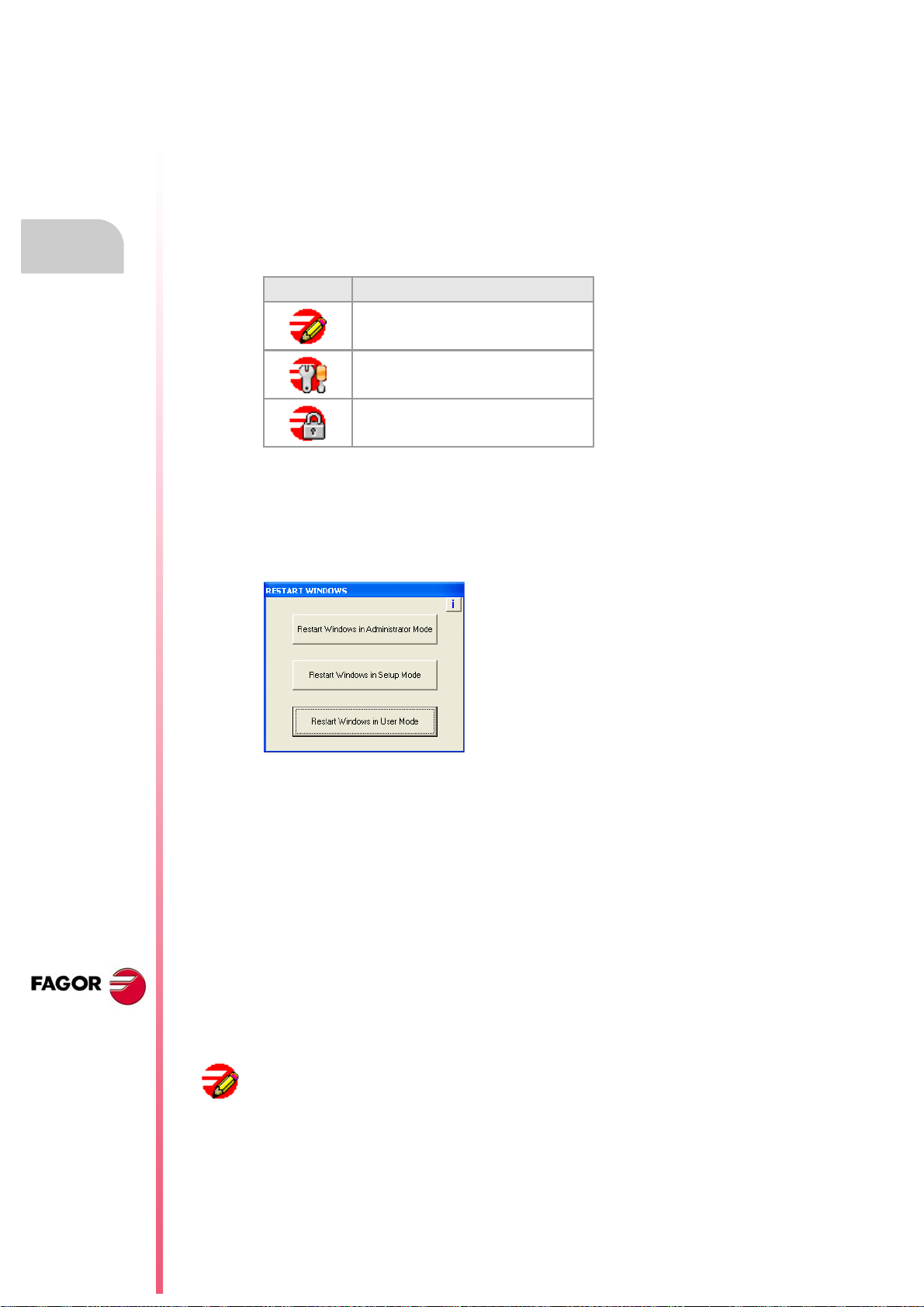
level. The unit shows the active work mode with an icon on the task bar of the operating
system, next to the clock. When the CNC is turned on, the status bar shows the active work
mode with icons.
Icon. Work mo de.
Administrator mode.
Setup mode.
User mode.
SOFTWARE INSTALLATION.
Software installation at the CNC.
These work modes will not be available when upgrading the software from a version where
the unit has a disk that is not write-protected (not read-only). Since it is not write-protected,
the changes made to it will remain.
Changing the work mode and that of the protected folders.
Protecting or unprotecting the folders.
When selecting the -i- at the top right hand side, the unit shows the list of folders and files
that are unprotected at the time. In administrator mode and the list of folders being visible,
pressing [CTRL]+[ALT]+[TAB]+[SHIFT] it is possible to protect or unprotect any folder or file
of the system that is not key for the proper operation of the CNC.
To change the work mode, the CNC application must be
turned off. The work mode is changed using the icon
that indicates the active work mode. When pressing this
icon, the unit shows the next window to switch from one
work mode to another. This process implies restarting
the unit and if the manufacturer has set it up this way,
it will also be necessary to enter the corresponding
password.
CNC 8065
(REF: 1309)
·26·
Peculiarities of each work mode.
Administrator mode.
The access to the administrator mode is enabled with the validation code ("Open system"
software option). If you don't have this software option, (i.e. you have a "closed system") you
will not be able to access the administrator mode and, therefore, you will not be able to install
third-party software.
This mode must only be used to install non-Fagor software or to change the system
configuration. There is not protection level in administrator mode, the whole disk is
unprotected. The CNC application does not start up in this mode.
Installation manual
ADMINISTRATOR MODE
SETU P MODE
The access to this mode is protected with the password "administrator mode", defined in the
utilities mode. When starting the unit up in this work mode, it will request the access
password.
The unit shows the following image on the desk, with red
background, indicating the active work mode and warning that it
is not a safe mode.
.
Setup mode.
This mode must only be used to update the CNC software and to set up the machine. The
setup mode has an intermediate protection level where everything that may be changed
while setting the machine up is unprotected.
The access to this mode is protected with the password "machine parameters", defined in
the utilities mode.
The unit shows the following image on the desk, with yellow
background, indicating the active work mode and warning that it
is not a safe mode.
.
User mode.
It is the usual work mode for the user, once the setup is completed. It has the maximum
protection level where only the folders and files that may be changed during the normal
operation of the machine are unprotected. Part-programs must be saved in the "..\USERS"
folder; the CNC considers the files saved in other folders as temporary files and will be
deleted when the CNC is turned off.
The access to this mode is not protected with the password.
1.
SOFTWARE INSTALLATION.
Software installation at the CNC.
CNC 8065
(REF: 1309)
·27·

1.
1.2 Software installation at the PC (simulator).
The CNC may be installed in the specific hardware that will later be mounted onto the
machine or at a table-top PC that will be used as a simulator for training purposes. The CNC
installed at a PC offers all the features and functions but it can only be used in simulator mode
and cannot be connected to any type of machine.
The CNC installation CD contains all that is necessary to install the software and the
documentation needed to install, set up and operate the CNC. The CNC software must be
installed in the hard disk of the PC; it cannot be executed directly from the CD. The installation
will start automatically when inserting the CD in the CD drive; if not, double-click on the
setup70_Vxx_xx.exe file, where Vxx_xx indicates the version to be installed. Then, follow
the instructions displayed on the screen.
Both at a CNC and at a PC (simulator), the necessary files for the CNC are located in the
folder C:\CNC8070 and its relevant subfolders. See "1.6 Software configuration." on page
34.
Minimum PC requirements.
In order for the CNC to run properly, its hardware must meet certain requirements.
• Windows® XP operating system.
• Internet Explorer 5.5 or newer.
SOFTWARE INSTALLATION.
Software installation at the PC (simulator).
• Pentium III microprocessor at 800 MHz.
• 512 Mb of RAM memory.
• 6x CD-ROM unit.
• Minimum screen resolution 800x600.
Installation manual
CNC 8065
(REF: 1309)
Installing the licenses.
Local license or network license.
During the installation, you will have to choose the type of license; local license (LOCAL) or
network license (NET). The type of license indicates where the dongle (hardware key) is
connected. For the dongle (hardware key) of he parallel port, always choose the local license.
• Choose the local license if the dongle (hardware key) will be connected to the PC where
the CNC software has been installed.
• Choose the net license if the dongle (hardware key) will be connected to a server. When
the CNC simulator needs to be authenticated, it will automatically look for the server
throughout the net. The CNC software needs not be installed at the server; however, the
software that enables the dongle (hardware key) must be installed at the server. This
software is included on the CD.
About the dongle (hardware key).
Fagor supplies two types of dongle (hardware key) to be connected either to the parallel port
or to the USB port. Once the software has been installed, in order to use the CNC, the dongle
(hardware key) supplied with the CD must be connected to the PC. If the net license was
chosen when installing the software, the dongle (hardware key) may be connected to a
server.
CNC setting; the MTB folder.
Both at a CNC and at a PC (simulator), the OEM has the folder ..\MTB to save the
modifications done at the CNC; such as the PLC program, the machine parameters, etc. The
CNC manages the MTB folders as follows.
• No MTB folder appears when installing the software for the first time. On system startup
and depending on the validation code, the system will move the corresponding folder from
..\CONFIGURATION to the CNC8070 and will rename it MTB.
• When changing the validation code, the system will return the MTB folder to the
..\CONFIGURATION folder and will give it its old name (MTB_M, MTB_T, etc); then, it
will move the corresponding folder from ..\CONFIGURATION to CNC8070 and will
rename it MTB.
·28·

Installation manual
• If the OEM has created the MTB folder manually, for example by copying it from a backup,
the system will not make any changes on power-up nor when modifying the validation
code.
Changing the language of the help files.
The help files are installed in English. The CD that comes with the product contains the help
files in different languages. You can change the help files installed by default with the ones
provided on the CD.
Locate the folder Help files inside the CD, select one of the available languages and copy
all the files to its CNC location. The help files installed at the CNC (or at the PC, if it is a
simulator) are located in the following folder.
C:\Cnc8070\Fagor\MMC\Help
The help files can only be in one language at a time at the CNC. The language of the help
files may be different from the one chosen for the interface.
1.
SOFTWARE INSTALLATION.
Software installation at the PC (simulator).
CNC 8065
(REF: 1309)
·29·

1.3 Updating the software version.
The updates must be carried out using the software supplied by Fagor Automation. Updating
the software maintains the set up of the machine parameters, PLC program, tool table and
tool magazine data. Before updating the software, check the list of possible incompatibilities
between versions.
Before updating the sofware.
Installation manual
1.
It is recommended to always have a backup copy of the full configuration (ASCII files) such
as machine parameter tables, tool tables, active-tools table and tool magazine tables as well
as the PLC program. Should any anomaly occur during the installation, these file will help
restore the CNC configuration.
Software update.
To update the software, close all the programs that may be running, including the CNC. The
software must be installed in setup mode.
The installation will start automatically when inserting the CD in the CD drive; if not, double-
Updating the software version.
SOFTWARE INSTALLATION.
click on the setup70_Vxx_xx.exe file, where Vxx_xx indicates the version to be installed.
Then, follow the instructions displayed on the screen.
When starting the process, the CNC offers the possibility of installing from scratch; in this
case, the installation process will not keep the CNC configuration like the machine
parameters, PLC program, etc.
Updating remote nodes of the CAN bus.
Every time the CNC is powered up, it verifies the versions of the remote nodes detected in
the CAN bus and automatically updates all these devices if necessary. When done loading,
it goes on with the usual start-up process.
If the loading is not successful, and, consequently, the software coherence between all the
elements of the CAN bus cannot be guaranteed, the CNC will display the corresponding error
message every time [RESET] is pressed.
CNC 8065
(REF: 1309)
·30·
 Loading...