

fagor 8065 Quick Reference

CNC
8065
Quick reference
(Ref: 1301)

CNC 8065. Quick reference.
INDEX
Screen description. 3
Description of the keys. 4
Jog mode. 7
MDI/MDA mode. 12
Automatic mode. 13
EDISIMU mode. 17
User tables. 19
Utilities mode. 20
Programming commands. 21
Technological functions. 21
List of auxiliary (miscellaneous) –M- functions. 22
List of –G- functions. 22
Canned cycles (·M· model). 26
Multiple machining (·M· model). 29
Canned cycles (·T· model). 32
High level language. 40
Probing canned cycles (·M· model). 43
Probing canned cycles (·T· model). 48
Operators and functions. 50
·2·
(Ref: 1301)
CNC 8065. Quick reference.
A
B C
D
A B C D E F
G H
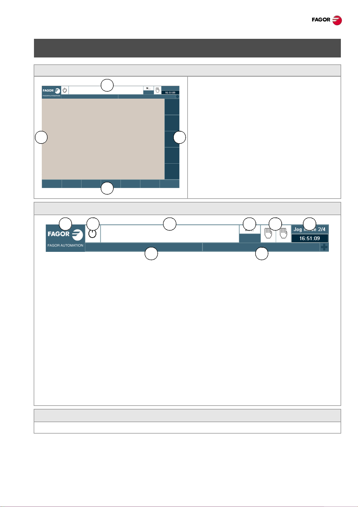
SCREEN DESCRIPTION.
General description of the interface.
A General CNC-status bar.
B Screen for the active work mode.
C Vertical softkey menu.
D Horizontal softkey menu.
General description of the interface.
A Icon (customizable) identifying the manufacturer . Clicking with the mouse or pressing on a touch-screen,
the CNC shows the task window (same as pressing the keystroke sequence [CTRL]+[A]) that shows
the list of the work modes and hotkeys of the CNC.
B Icon showing the status of the program of the active channel:
C Program selected in the active channel for execution. Clicking with the mouse or pressing a touch-screen
has the same effect as the [Main-Menu] key, which shows the initial screen of the CNC.
D Number of the block in execution. The bottom icon indicates that the Single-block execution mode is
active.
E Number of channels available and active channel (indicated in blue). Icons show which operating mode
each channel is in. Clicking with the mouse or pressing a touch-screen to access the desired channel,
doing it on the icon of the active channel, has the same effect as the [ESC] key.
F Active work mode (automatic, manual, etc.) selected screen number and total number of screens
available. System clock. By clicking on the active work mode, the CNC shows the list of available pages
and which ones are visible.
G Active CNC message.
H PLC messages.
Turn the CNC off.
[ALT][F4] Turn the CNC off.
·3·(Ref: 1301)
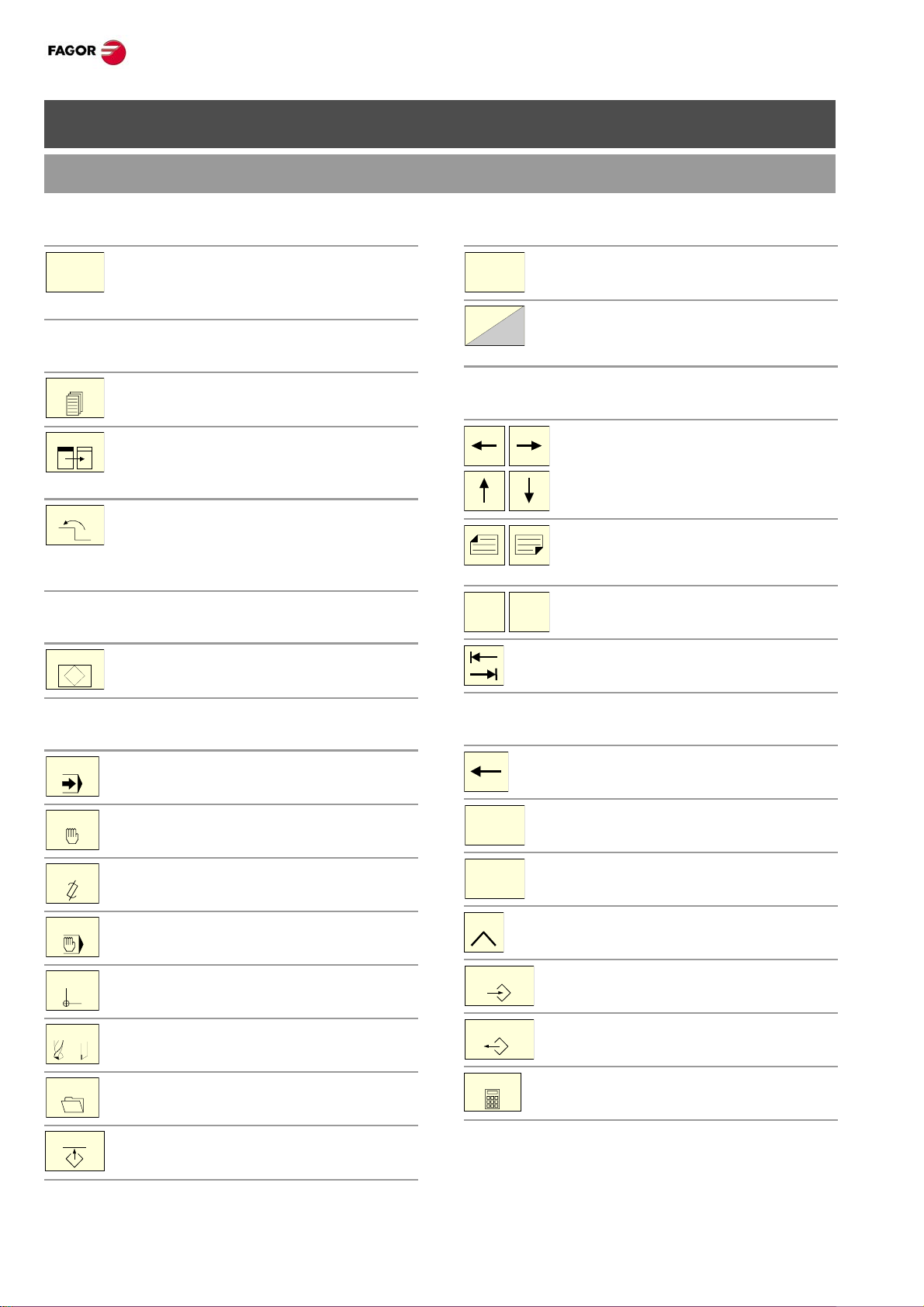
DESCRIPTION OF THE KEYS.
F1
NEXT
FOCUS
BACK
HELP
?
AUTO
MANUAL
EDIT
MDI
TABLES
TOOLS
UTILITIES
CUSTOM
MAIN
MENU
ENDHOME
DEL
INS
ESC
ENTER
RECALL
CALC
MONITOR & KEYBOARD.
CNC 8065. Quick reference.
Function keys.
Softkeys.
Keys F1 through F12 select the options of
the softkey menus.
Browsing keys.
NEXT key.
OEM configurable table.
FOCUS key.
It is used to switch between the different
windows of the screen.
BACK key.
On the horizontal soft key menu, it may be
used to go from a softkey submenu up to
the previous menu.
Help key.
HELP key.
Display CNC help.
Browsing keys.
Main menu.
Changing the state of an icon. In the
MC/TC mode, it toggles between the
standard and the auxiliary screens.
Keys to move the cursor.
The arrow keys move the cursor one
position to the left, right, up or down.
The previous-page or next-page keys
show the previous or next page at the
part-program or PLC program editor.
The home and end keys move the cursor
the beginning or end of the line.
The tab key moves the cursor to the next
field of the active menu.
Work modes.
Automatic mode.
Jog mode.
EDISIMU mode.
MDI/MDA mode.
User tables (zero offsets, fixtures and
arithmetic parameters).
Tool and magazine table.
Utilities mode.
Configurable mode.
OEM configurable table.
Editing keys.
Delete.
Delete.
Insert or overwrite.
Escape key, to cancel the current action
without assuming the changes.
Key to validate commands, data and
program blocks of the editor.
Recover data.
Calculator (*).
(*) The calculator key is not available on all keyboards.
·4·
(Ref: 1301)
CNC 8065. Quick reference.
CNC
OFF
X+ 7+
X- 7-
X 7
_
+
10000
1000
100
10
1
100
10
1
jog
200
190
180
170
160
150
140
130
120
110
100
90
80
70
60
50
40
30
20
10
4
2
0
FEED
RESET
SINGLE
ZERO
_
+
200
190
180
170
160
150
140
130
120
110
100
90
80
70
60
50
40
30
20
10
4
2
0
SPEED
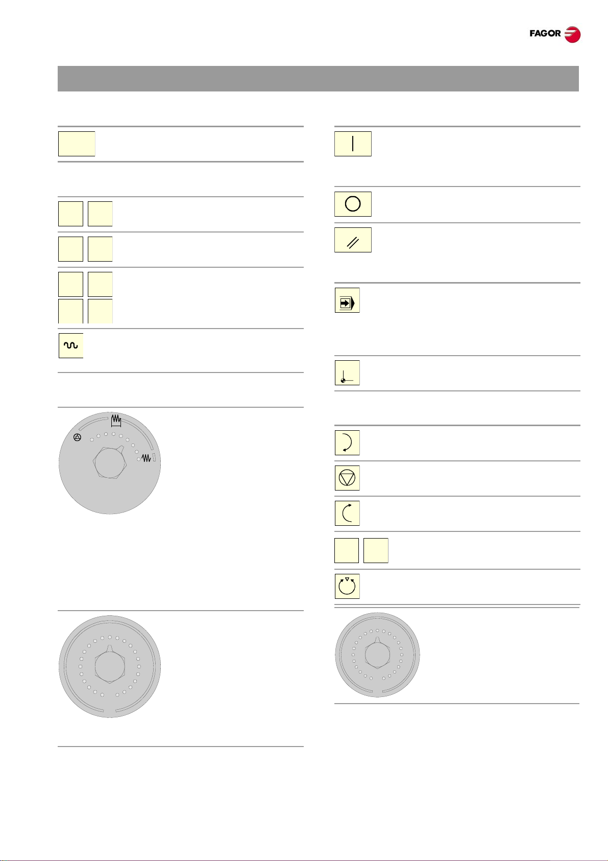
JOG PANEL.
Turn the CNC off.
Turn the CNC off.
Jog keyboard for jogging the axes.
Keys to select axes and jog them in the
positive direction.
Keys to select axes and jog them in the
negative direction.
Keys to select the axes and keys to select
the jogging direction. Both keys (axis and
direction) must be pressed to jog the axis.
Rapid key. When pressing this key while
moving an axis, the CNC applies the
rapid feedrate.
Feed selectors.
Execution keys.
Cycle start key (START).
Execute the selected program in
automatic mode, a block in MDI/MDA
mode, etc.
Cycle stop key (STOP).
Interrupt the execution of the CNC.
Reset key.
It initializes the system setting the initial
conditions as defined by machine
parameters.
Single-block execution mode.
When selecting the "single block"
execution mode, the program simulation
will be interrupted at the end of each
block.
Home search.
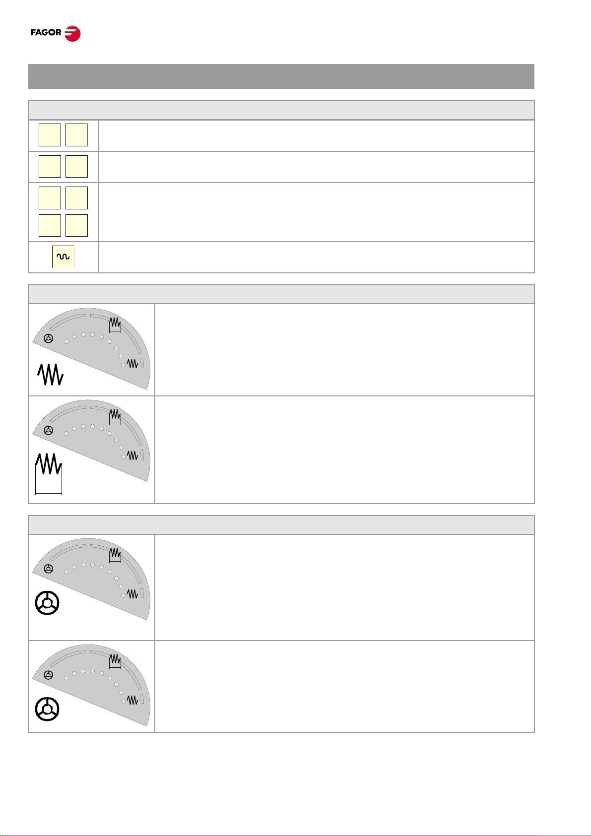
Sector for the type of jog; continuous / incremental jog
or handwheels.
• In handwheel mode, it selects the multiplying factor
for the handwheel pulses (x1, x10 o x100).
• In incremental mode, it select s the incremental value
of the axis movements.
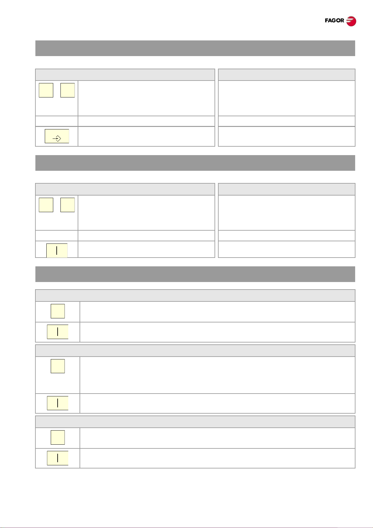
Spindle control.
Start the spindle clockwise.
Stop the spindle.
Start the spindle counteclockwise.
To vary the spindle speed percentually.
Spindle orientation.
Selector of percentage of
spindle speed override
between 0% and 200%.
Selector of percentage of feedrate override , between 0%
and 200%, for jog and automatic movements.
·5·(Ref: 1301)

KEYBOARD SHORTCUTS.
MAIN
MENU
AUTO
MANUAL
EDIT
MDI
TABLES
TOOLS
UTILITIES
CALC
BACK
FOCUS
NEXT
RESET
SINGLE
CNC 8065. Quick reference.
Operations at the interface.
[CTRL] + [W]
Minimize/Maximize the CNC.
[CTRL] + [J]
Show / hide the virtual operator panel.
[CTRL] + [M]
Show / hide the PLC message list.
[CTRL] + [O]
Show / hide the CNC message list.
[ALT] + [W]
Show / hide the window for errors and warnings.
[ALT] + [F4]
Turn the CNC off.
Work modes.
[CTRL] + [A]
To show the task window.
Browsing keys.
[CTRL] + [F1]
Previous menu.
[CTRL] + [F2]
Switch window.
[CTRL] + [F3]
Switch screens.
[ALT]+[B]
Two-colored key.
Execution keys.
[CTRL]+[S]
Cycle start key (START).
[CTRL]+[P]
Cycle stop key (STOP).
[CTRL]+[R]
Reset key.
[CTRL] + [SHIFT] + [F1]
Main menu.
[CTRL] + [F6]
Automatic mode.
[CTRL] + [F7]
Jog mode.
[CTRL] + [F9]
EDISIMU mode.
[CTRL] + [F8]
MDI/MDA mode.
[CTRL] + [F10]
User tables.
[CTRL] + [F11]
Tool and magazine table.
[CTRL] + [F12]
Utilities mode.
[CTRL] + [K]
Calculator.
[CTRL] + [B]
Single-block execution mode.
The shortcuts for the [START] [STOP] and
[RESET] keys are only available when the CNC is
installed as simulator on a PC.
·6·
(Ref: 1301)
CNC 8065. Quick reference.
X Z
...
ZERO
ZERO
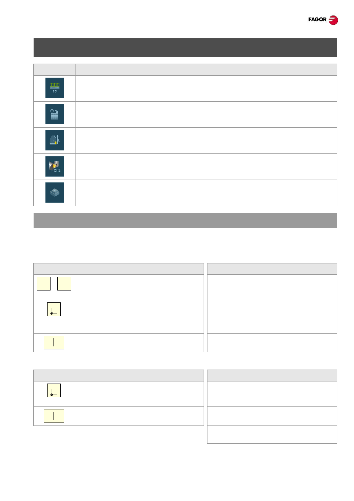
JOG MODE.
Softkey. Description.
Change the units for data display (mm or inches). For programming, the CNC assumes the
units defined with the active function G70 or G71, or, when not programmed, the unit s se t
by the machine manufacturer (INCHES parameter).
Setting and activating the zero offsets and the fixture offsets. This softkey shows the zero
offsets and the fixture offset s of the system, either to store the active zero offset or to activate
a new zero offset.
Tool calibration (·M· model).
Tool calibration (·T· model).
Part centering (·M· model).
HOME SEARCH.
Manual home search (one axis at a time).
The axis-by-axis home search cancels the zero offset, the fixture o ffset and the measuring of fset. The CNC
assumes the machine reference zero point (home) as the new part zero.
Keyboard. Softkey menu.
1 Select the axis to be homed (on
alphanumeric keyboard). The CNC will
highlight the coordinate of that axis.
2 Press the homing key [ZERO]. The CNC
will display the symbol “1” in the numeric
area.
3 Press [START] to go ahead with the home
search or [ESC] to cancel the operation.
Automatic home search (with subroutine).
Keyboard. Softkey menu.
1 Press the homing key [ZERO]. The CNC
will display the symbol “1” in the numeric
area.
1 Press the home search softkey to show
the list of axes of the channel.
2 Select the axis to be homed on the softkey
menu. The CNC will highlight the
coordinate of that axis and will show the
symbol “1” in the numeric area.
3 Press [START] to go ahead with the home
search or [ESC] to cancel the operation.
1 Press the home search softkey to show
the list of axes of the channel.
2 Press [START] to go ahead with the home
search or [ESC] to cancel the operation.
·7·(Ref: 1301)
2 Select the “All” option on the softkey
menu.
3 Press [START] to go ahead with the home
search or [ESC] to cancel the operation.
MOVE THE AXES.
X+ 7+
X- 7-
X 7
_
+
10000
1000
100
10
1
100
10
1
jog
10000
1000
100
10
1
100
10
1
jog
jog
10000
1000
100
10
1
100
10
1
jog
10000
1000
100
10
1
100
10
1
jog
JOG keypad.
Select an axis and move it in the positive direction.
Select an axis and move it in the negative direction.
Keys to select the axes and keys to select the jogging direction. Both keys (axis and direction)
must be pressed to jog the axis.
Move the axis in rapid.
Jog
Movement in continuous jog.
In continuous jog, the axes keep moving while the jog keyboard is acted upon.
1 Turn the jog selector switch to the continuous JOG position.
2 Jog the desired axis using the JOG panel (keypad).
CNC 8065. Quick reference.
Movement in incremental jog.
In incremental jog, the axis moves a specific distance every time the key is
pressed.
1 Turn the jog selector switch to one of the incremental jog positions.
2 Jog the desired axis using the JOG panel (keypad). Every time the JOG panel
is acted upon, the axis will move the distance indicated on the dial of the jog
selector switch.
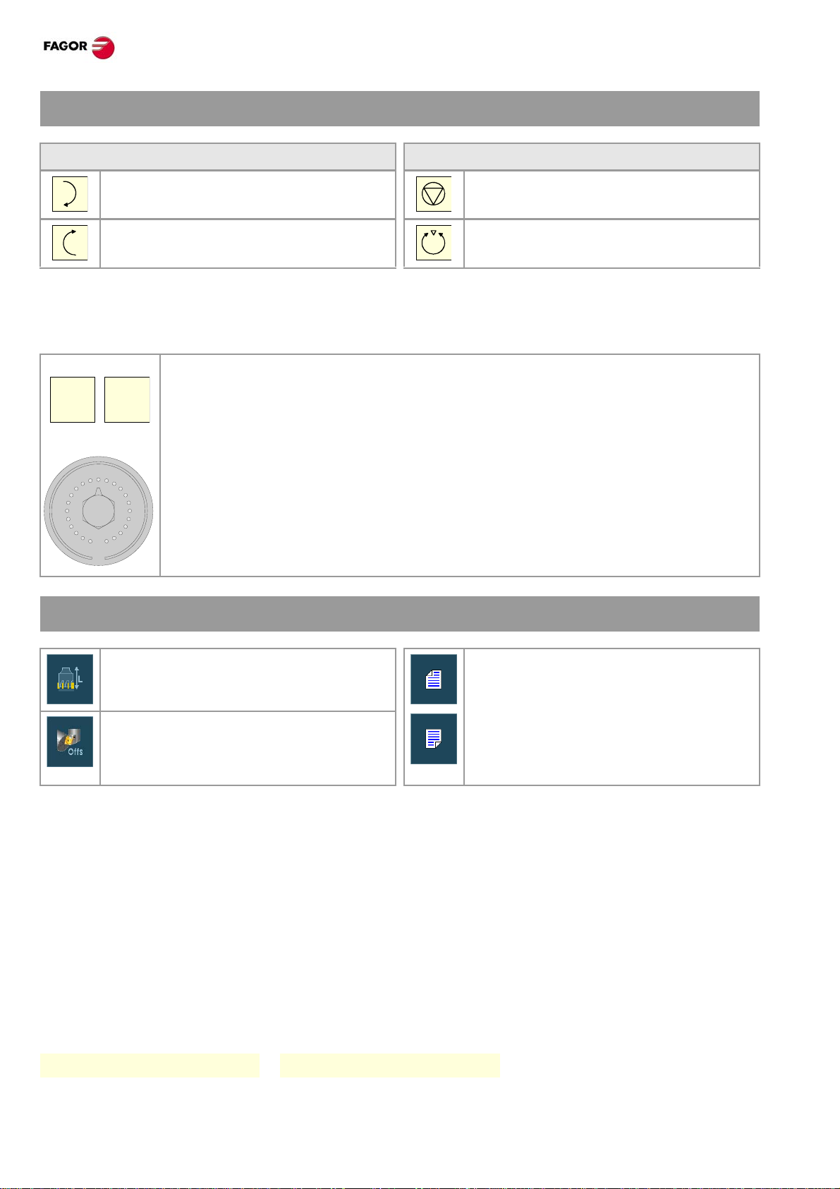
Jogging the axes with handwheels.
General handwheel (it may be used to jog any axis of the machine).
1 Turn the jog selector switch to one of the handwheel positions.
2 Select the axis or axes to be jogged on the jog keyboard. The CNC will
highlight the selected axes.
3 Once the axis has been selected, the CNC will move it as the handwheel is
turned depending on the setting of the selector switch and on the turning
direction of the handwheel.
Individual handwheel (it is associated with a particular axis).
1 Turn the jog selector switch to one of the handwheel positions.
2 The CNC moves each axis as its relevant handwheel is turned depending on
the setting of the selector switch and on the turning direction of the
handwheel.
·8·
(Ref: 1301)
CNC 8065. Quick reference.
X Z
...
ENTER
X Z
...
FST
COORDINATE PRESET.
The [ESC] key may be used to cancel the operation at any time.
Keyboard. Softkey menu.
1 Select the axis to be preset (on
alphanumeric keyboard). The CNC will
highlight the coordinate of that axis.
2 Key in the desired preset value. 2 Key in the desired preset value.
3 Press [ENTER] to assume the entered
value.
1 Press the softkey for presetting axes to
show the list of axes of the channel and
select an axis. The CNC will highlight the
coordinate of that axis.
3 Press [ENTER] to assume the entered
value.
MOVE AN AXIS TO A PARTICULAR POSITION.
The [ESC] key may be used to cancel the operation at any time.
Keyboard. Softkey menu.
1 Select the axis to be moved (on
alphanumeric keyboard). The CNC will
highlight the coordinate of that axis.
2 Enter the coordinate of the target point. 2 Enter the coordinate of the target point.
3 Press [START] to make the move. 3 Press [START] to make the move.
1 Press the softkey for presetting axes to
show the list of axes of the channel and
select an axis. The CNC will highlight the
coordinate of that axis.
SET THE FEEDRATE, SPEED OR TOOL.
Feedrate.
1 Press [F] at the alphanumeric keyboard.
2 Enter the new feedrate.
3 Press [START] to assume the entered value or [ESC] to cancel the operation.
Speed.
1 Press [S] at the alphanumeric keyboard until selecting the desired spindle. When
pressing this key for the first time, the CNC will highlight the relevant data indicating that
it is selected.
2 Enter the new spindle speed.
3 Press [START] to assume the entered value or [ESC] to cancel the operation.
Tool.
1 Press [T] on the alphanumeric keyboard.
2 Enter the tool to be selected.
3 Press [START] to assume the entered value or [ESC] to cancel the operation.
·9·(Ref: 1301)
MASTER SPINDLE CONTROL.
_
+
200
190
180
170
160
150
140
130
120
110
1009080
70
60
50
40
30
20
10
4
2
0
SPEED
CNC 8065. Quick reference.
Start the spindle clockwise (same as M03
Stop the spindle (same as M05 function).
function) at the active speed.
Start the spindle counterclockwise (same
Orient the spindle (same as M19 function).
as M04 function) at the active speed.
Vary the speed override from the operator panel.
With the operator panel, it is possible to change the percent age of spindle speed using th e jog keyboard or
a switch (depending on model).
JOG keypad.
Increases or decreases the percentage of spindle speed. The maximum and minimum
values as well as the incremental step are set by the OEM, the typical values being a
variation between 50% and 120% with a 5% step.
Switch.
It sets the percentage of turning speed to be applied. The maximum and minimum values
are set by the OEM, the typical values being a variation between 50% and 120%.
TOOL CALIBRATION.
Tool calibration in a mill model. If there is no tabletop probe, only manual
calibration is available. All types of
calibration are available when using a
Tool calibration in a lathe model.
• Manual calibration.
(Calibration without probe).
In this mode, only the active tool can be calibrated. Since there
is no probe, a reference part is required to calibrate the tool.
All the movements are carried out manually.
• Semi-automatic calibration.
(Calibration with probe).
• Automatic calibration.
(Calibration with probe).
The positioning movements are carried out manually and the
CNC executes the probing movements.
The CNC executes all the movements using the calibration
canned cycle #PROBE.
Probe selection.
The CNC uses the active probe for calibration. The active probe may be changed via part-program or MDI
using the instruction #SELECT PROBE.
table-top probe. The different calibration
methods may be selected from the vertical
softkey menu.
#SELECT PROBE [1] #SELECT PROBE [2]
·10·
(Ref: 1301)

CNC 8065. Quick reference.
Manual calibration. Calibration without a probe.
All the movements are carried out manually . Since there is no probe, a reference part is required to calib rate
the tool. The calibration consists in moving the tool manually until it touches the p art and then validating the
calibration on each axis. In this mode, only the active tool can be calibrated.
• Milling model. Calibrate the length of the endmills and the offsets of the lathe tools.
• Lathe model (plane). Calibrate the offset of any tool.
• Lathe model (trihedron). Calibrate the length or offsets of the endmills and the of fsets of the lathe tools.
Tool calibration steps.
1 Define the dimensions of the reference part being used in the calibration.
2 Define the tool and the offset to be calibrated and press [STAR T] to execute the tool change (if [ENTER]
is pressed, the CNC will only show the tool data).
3 Calibrate the tool. Approach the tool manually until touching the part and then validate the calibration using
the softkey menu. After validating the calibration, it updates the values and initializes the wear value to
zero. Them, the new values are saved in the tool table.
4 Press [START] for the CNC to assume the new values of the offset.
Semi-automatic calibration. Calibration with a probe.
The positioning movements are carried out manually and the CNC e xecutes the prob ing movements. The
CNC will move the tool on the selected axis until it touches the probe and validates the calibration only on
that axis. In this mode, only the active tool can be calibrated.
• Milling model. Calibrate the length or radius of the endmills and the of fsets of the lathe tools.
• Lathe model. Calibrate the offset of any tool.
Tool calibration steps.
1 Define the probing distance and feedrate. If the feedrate is not defined, the probing movement will be made
at the feedrate set by the OEM.
2 Define the tool and the offset to be calibrated and press [STAR T] to execute the tool change (if [ENTER]
is pressed, the CNC will only show the tool data).
3 Manually approach the tool to the probe until it is placed on the path that will be used for probing. To
calibrate the radius with a cylindrical probe, the path must coincide with the probe's center point; if not,
the radius will be calculated wrong.
4 Calibrate the tool. Select the axis and the probing direction on the softkey menu and press [ST ART]. The
probe moves in parallel to the axis and in the selected direction until touching the probe. It updates the
measured value and resets the wear value to zero. The data is stored in the tool table.
5 Once the tool has been calibrated, the CNC shows a message proposing to press [STAR T] so the CNC
assumes the new values of the offset. When pressing [ST ART] while this message is displaye d, the CNC
assumes the new values of the offset; if the message is not displayed, pressing [START] executes the
probing movement again.
·11·(Ref: 1301)

CNC 8065. Quick reference.
Automatic calibration. Calibration with a probe and a canned cycle.
The calibration is done using a probing canned cycle. The CNC moves the tool until touching the probe and
validates the calibration on each axis. This mode may be used to calibrate any tool.
• Milling model. Calibrate the length, the radius or offsets of the endmills and the of fsets of the
lathe tools.
• Lathe model (plane). Calibrate the offset of any tool.
• Lathe model (trihedron). Calibrate the length, the radius or offsets of the endmills and the of fsets of the
lathe tools.
Tool calibration steps.
1 Select the tool and the offset to be calibrated.
2 Define the data defining the calibration.
3 Press the [CYCLE START] key to start the calibration. The CNC calibrates the tool making all the
necessary movements; there is no need to manually approach the tool. If necessary , the CNC makes the
tool change.
4 After the calibration It updates the tool table data. Also, the CNC assumes the new values.
MDI/MDA MODE.
Edit new blocks.
• In MDI mode, the edit line is always visible.
• In MDA mode, one must select the "new block" option from the softkey menu.
Modify a block from the block history.
• In MDI mode, use the [][] keys to pop-up the history and scroll it. The [ENTER] key restores from the
history the block selected with the cursor and insert it in the edit line.
• In MDA mode, use the [][] keys, select a block from the histor y and use the "modify" option from the
softkey menu (or the [ENTER] key to copy it into the edit line.
Execute blocks.
• The [START] key executes the block currently displayed on the editing line. Once the block has been
executed is saved in the block history.
• The [STOP] key interrupts the execution of the block. Press [START] again to resume execution from
where it was interrupted.
While the execution is interrupted, the “CANCEL” softkey cancels the execution of
the block while keeping the programmed machining conditions (it does not do a
general reset of the CNC).
• The [RESET] key cancels the execution of the block and resets the CNC to its initial conditions.
·12·
(Ref: 1301)
CNC 8065. Quick reference.
RESET
SINGLE
AUTOMATIC MODE.
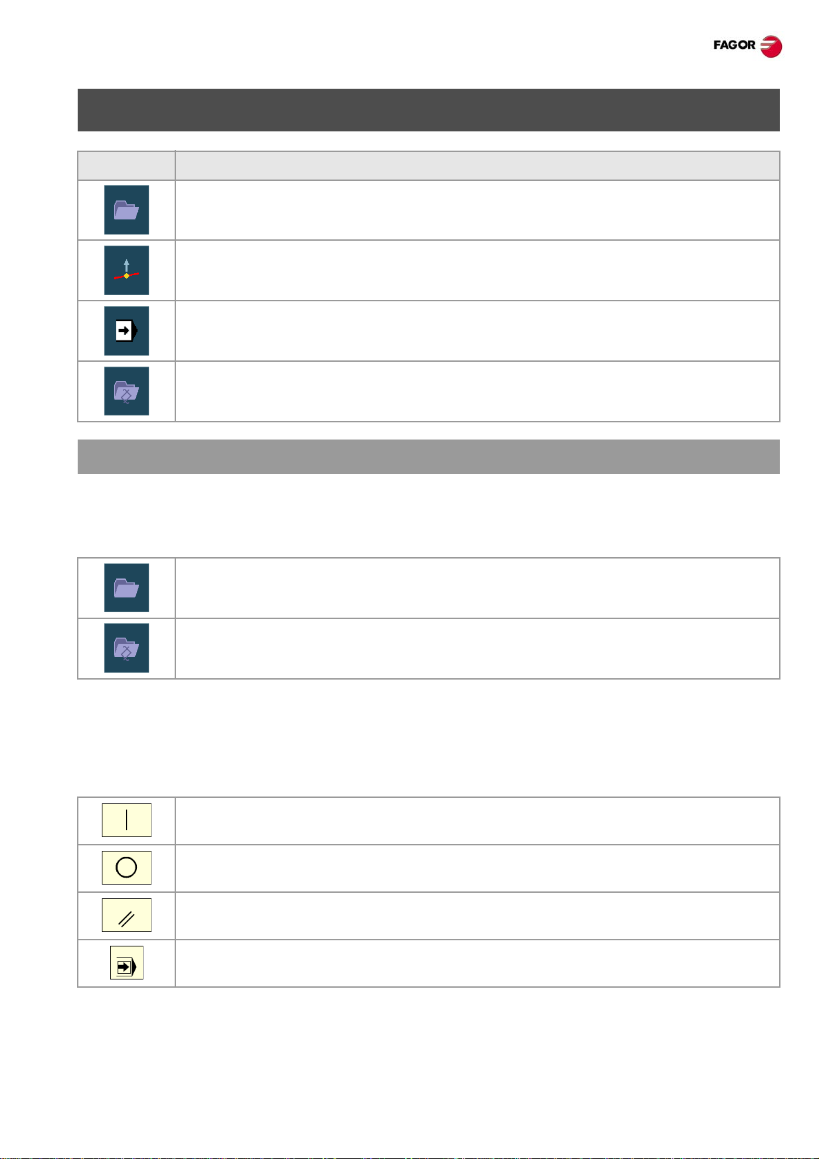
Softkey. Description.
Select a program for execution.
Begin tool inspection. Tool inspection is only a vailable when program execution is
interrupted.
End simulated execution and start executing the program
Select the program that is being edited.
PROGRAM EXECUTION.
Select a program.
Each channel executes the program selected in it. To select a program, press one of the following softkeys
of the vertical menu.
This softkey shows the list of available programs.
This softkey directly selects the program of the EDISIMU mode.
Execute a program.
The name of the program selected in the channel for execution appe ars on the general status bar. If not
indicated otherwise, the program execution will begin from the first block of the program to the execution
of one of the end-of-program functions "M02" or "M30". As an option, it is possible to define the first and last
blocks of the execution.
To start the execution of the program, press [START] on the Operator Panel.
The [STOP] key interrupts the execution of the program. Press [START] again to resume
execution from where it was interrupted.
The [RESET] key cancels the execution of the program and resets the CNC to its initial
conditions.
Single-block execution mode. The program may be executed in –single block– or
–automatic– mode; the mode may be selected even while executing the program.
·13·(Ref: 1301)
CNC 8065. Quick reference.
EXECUTE BLOCKS SEPARATELY.
Press the “EXBLK” softkey of the horizontal menu. Being this option active, every time the [START] key is
pressed, it only executes the block selected in the active program. Once that block is executed, another block
may be executed by selecting it with the cursor and pressing [START] again and so on. Blocks executed
like this change the history of the M and G functions.
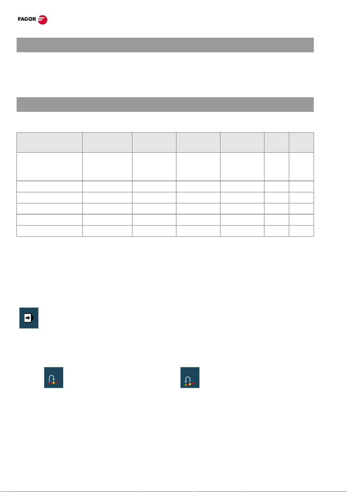
SIMULATED EXECUTION OF A PROGRAM.
With simulated execution, it is possible to simulate a program, interrupt it at a point and st art execution from
that point on. Depending on the type of simulation selected, it can involve movement of axes, spindle, etc.
Tool path Movement of
the axes
Theoretical travel. Programmed
tool path
G functions. Tool center No No No Yes Yes
G M S T functions. Tool center No No Yes Yes Yes
Main plane. Tool center Yes (plane) Yes Yes No Yes
Rapid. Tool center Yes Yes Yes No Yes
Rapid [S=0]. Tool center Yes No Yes No Yes
Start the simulation of the program
1 On the horizontal softkey menu, select the desired type of simulation.
2 If necessary, set the desired simulation conditions (first and last block)
3 Press the [START] key to start the simulation. The program may be simulated in "single block" or
"continuous" mode; the mode may be selected even while simulating the program.
End simulation and start executing the program.
No No No Yes Yes
Spindle
control
Send to the
PLC M-H-S-T
G04 M00
M01
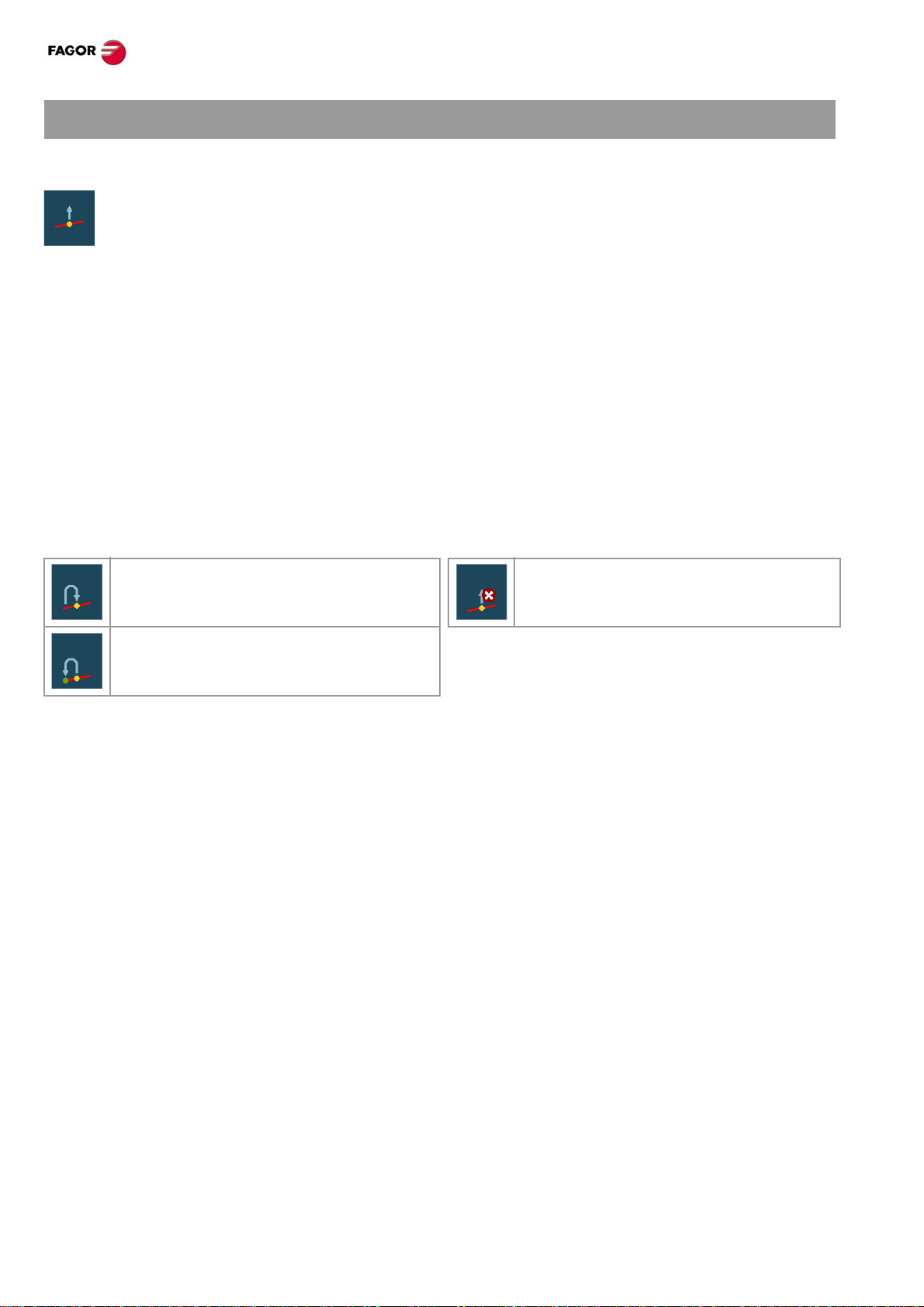
1 Press the [STOP] of the operator panel to interrupt the simulation. Once the program is
interrupted, simulation may be resumed with the [ST ART] key or switch to execution mode from
the vertical softkey menu.
2 When switching to execution mode (after pressing the softkey), the CNC goes into tool
inspection to reposition the axes, modify pro gram conditions, etc. To complete the tool
inspection and before starting the execution of the program, the spindle turning direction must
be restored and the axes repositioned. The vertical softkey menu offers two options.
• Repositioning the axes at the
interruption point.
3 Press the [START] key to start the execution.
·14·
• Repositioning the axes at the starting
point of the interrupted block.
(Ref: 1301)

CNC 8065. Quick reference.
BLOCK SEARCH.
With block search, it is possible to recover the program history up to a particular block in such way that if
program execution is resumed at that block, it will do so with the same conditions as if it were executed from
the beginning.
• The automatic block search may be used to recover the program history up to the block where the previous
execution was canceled. The CNC remembers the block where interruption was canceled, thus not being
necessary to set the stop block.
• The manual block search may be used to recover the program history up to a particular block of the
program or of the subroutine, set by the operator.
Executing block search.
1 Selecting the type of search: automatic or manual.
2 Selecting the stop block. In the automatic block search, there is no need to select the stop block; by default,
the CNC runs the search up to the block where the program was interrupted.
3 Selecting the starting block for the search. If the first block is not selected, the block search starts at the
beginning of the program.
4 Press the [CYCLE START] key to start the block search.
5 Depending on how the treatment of functions M, H, F , S is configured, it may be necessary to decide which
ones are sent out to the PLC.
6 Reposition the axes to the point to resume execution.
7 Tool inspection may be accessed to change the machining conditions.
8 Press [START] to execute the program.
Repositioning the axes.
Once the block search is finished, the CNC will show the axes that are out of position. The axes may be
repositioned individually or several at the same time in one of the following ways:
• Manual repositioning of axes. Jog the axes with the handwheels or with the JOG keys. The movement
is limited by the repositioning end point and the corresponding software limit.
• Automatic repositioning of axes. Select the axes with the relevant softkey and press [START].
Repositioning may be interrupted (using the [STOP] key) to select other axes.
Changing the machining conditions.
After positioning the axes and before resuming execution, tool inspection may be accessed to change the
machining conditions. In tool inspection, it is possible to change the feedrate a nd the spindle speed, execute
blocks in MDI/MDA mode as well as activate M and H functions.
·15·(Ref: 1301)
CNC 8065. Quick reference.
TOOL INSPECTION.
Begin tool inspection.
T ool inspection may be accessed from the vertical sof tkey menu only when the execution of the
program has been interrupted ([STOP] key). After activating tool inspection, it is possible to jog
the axes using the jog keyboard, act upon the master spindle of the channel from the operator
panel and execute blocks from the MDI/MDA mode.
Execute blocks in MDI/MDA mode.
Any program block may be executed in MDI/MDA mode. The conditions when entering the MDI/MDA mode
will be those of the interruption point; i.e. the CNC mainta ins the history of active G and M functions, feedrate,
spindle speed, tool and other commands that were programmed. However , the CNC treats certain functions
and commands (type of movements, radius compensation, etc.) differently. Refer to the operating manual.
In general, all the changes made in MDI/MDA mode are kept active when resuming the p rogram af t er tool
inspection except the following functions that are restored at the time of interruption; type of interpolation
(G00, G01, G02, G03, G33 or G63), G90/G91 function or #MCS function.
Repositioning the axes and the spindle.
To complete the tool inspection and before resuming the execution of the program, the spindle turning
direction must be restored and the axes repositioned.
Repositioning the axes at the interruption
Canceling repositioning.
point.
Repositioning the axes at the starting point
of the interrupted block.
Repositioning the axes.
The CNC allows repositioning the axes either one by one or in groups. Use the vertical softkeys to select
the axes to be repositioned and press [START]. The CNC will reposition the axes at the selected point
(according to the softkey selected earlier) at the feedr ate set by the machine manufacturer. Once one axis
has reached its position, it will no longer be available.
Repositioning the master spindle.
If the status of the master spindle has changed durin g the inspection, the softkeys will show the M3, M4, M5
or M19 function to restore. The spindle turning status may be restored either together with th e repositioning
of the axes or separately . If the spindle was interrupted in a positioning with M19, repositioning will complete
that positioning.
Resuming the execution of the program.
Once all the axes are repositioned or after canceling repositioning, press [START] to resume program
execution.
• If tool inspection has ended by repositioning all the axes, when pressing [START], the CNC completes
the interrupted path and goes on with the rest of the program.
• If tool inspection has ended af ter canceling the repositioning of the axes, when pressing [STAR T], the axes
move from their current position to the end point of the interrupted path and then the CNC goes on with
the rest of the program.
·16·
(Ref: 1301)
 Loading...