

Page 1
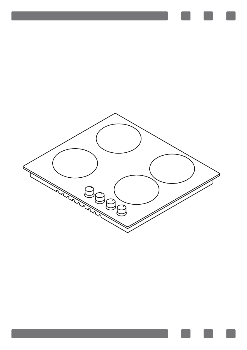
BUILT-IN COOKTOP
Gas & Electric Cooktop
USER MANUAL
G GB
NÁVOD NA POUŽITÍ CZ
NÁVOD NA POUŽITIE
SK
Page 2

GB
Dear User,
Our objective is to make this product provide you with the best output
which is manufactured in our modern facilities in a careful working environment, in compliance with total quality concept.
Therefore, we suggest you to read the user manual carefully before
using the product and, keep it permanently at your disposal.
Note: This user manual is prepared for more than one model. Some
of the features specied in the Manual may not be available in your
appliance.
All our appliances are only for domestic use, not for commercial use.
“Conforms with the WEEE Regulations.”
2
Page 3

CONTENTS
GB
Important Warnings
Introduction Of The Appliance
Control Panel
Electrical Connection Scheme
Important Warnings
Setting Gas Cooktops As Per Gas Type
If Built-In Oven Is Placed Under Cooktop
Installation Of Cookstop
Counter Cutting Sizes And Installation Of Your Cooktop
Correct Place For Installation
Ventilation Of Room
Transformation From Natural Gas To Lpg And
From Lpg To Natural Gas
Gas Breaking Safety Appliance (Ffd)
Usage Of Your Cooktop
Maintenance And Cleaning
Troubles And Solution Proposals
Environmentally-Friendly Disposal And
Package Information
4
6
7
7
8
10
11
11
13
14
14
15
15
16
18
19
20
3
Page 4

GB
IMPORTANT WARNINGS
1. WARNING: Before touching the connection terminals,
all supply circuit should be disconnected.
2. WARNING: Any inadvertent cooking made with fats and
oils can be dangerous and cause re.
3. WARNING: Risk of re; do not store the food materials
on the cooking surface.
4. WARNING: During usage the reachable sections can
be hot. Keep the small children away.
5. WARNING: The appliance and its reachable sections
become hot during usage.
6. The setting conditions of this appliance is indicat-
ed on the label. (Or data tag)
7. This appliance is not connected to a combustion
product discharge system.This appliance shall be connected and installed as per the applicable installation
legislation. Consider the requirements related with ventilation.
8. Using a gas hob will release humidity and combus-
tion products in the room where it resides. Especially
during when the appliance in use, ensure that the kitchen is well ventilated and retain the natural ventilation
holes or install a mechanical ventilation system. (Hood
on top of the oven) Sustained usage of the appliance
may require additional ventilation. For example opening a window or if available, increasing the ventilation
level of a mechanical ventilation system.
9. WARNING: The appliance is intended for cooking only.
It must not be used for other purposes like room heating.
4
Page 5

GB
10. This appliance should be installed as per regula-
tions and in well-ventilated location only. Read the instructions before installing or operating the appliance.”
11. Before placing the appliance check the local con-
ditions (gas type and gas pressure) and ensure that the
settings of the appliance is appropriate.
12. These instructions are applicable for countries of
which symbols are indicated on the appliance. If the
country symbol is not available on the appliance, in
order to adapt the appliance to the conditions of such
country, the technical instructions should be read.”
13. Do not operate the system for more that 15 sec-
onds. If the burner does not ignite at the end of 15
seconds stop the operation of the system and open the
section door and/or wait for at least 1 minute before
igniting the burner.
14. Do not use steam cleaners to clean the appliance.
15. NEVER try to extinguish a re with water, rst dis-
connect the mains supply and then using, for example
a lid or blanket, cover the re.
16. Unless continuous supervision is provided, the
children of age 8 or below should be kept away.
17. Pay attention for not to touch the heating ele-
ments.
18. This appliance can be used by children aged from
8 years and above and persons with reduced physical,
sensory or mental capabilities or lack of experience and
knowledge if they have been given supervision or instruction concerning use of the appliance in a safe way
and understand the hazards involved.
5
Page 6

INTRODUCTION OF THE APPLIANCE
1
3
4 5 6 7
GB
2
8
11
1 - Burner positions
2- Glass or Metal Surface
3- Control Buttons
4- Small Burner
5- Medium Burner
6- Large Burner
9 10
12
7 - WOK Burner
8- Hotplate
9- Coffee Adaptor
10-Wok Burner Adaptor
11- Cast Grill
12- Enamel Grill
6
Page 7

CONTROL PANEL
GB
Cooktop Panel Visual of 70-90 cm and 100 cm
Cooktop Panel Visual of 60 cm
Cooktop Panel Visual of 45 cm
ELECTRICAL CONNECTION SCHEME
Get electrical connection of your appliance done to authorized person in
line with the following scheme.
220-240V~50/60Hz
L1
H05 VV-F 3G 1.5mm²
Neutral
Neutre
Earth
Terre
Erdung
7
Page 8

GB
IMPORTANT WARNINGS
Electrical Connection and Safety
1.Setting conditions of this appliance is indicated in tag or data plate.
2.This appliance is not connected to any discharging apparatus of burn-
ing products. It should be connected and installed according to applicable assembly regulation.
3.Great attention should be paid on ventilation related conditions.
4.Your appliance should be connected to an appropriate fuse according to
electric power. If necessary, it is recommended that connection is made by
authorized service.
5.Your appliance is congured in accordance with electrical supply of
220-240V AC/380-415V3N AC 50/60Hz.
6.If main electrical network is different from these values, contact with
your authorized service.
7.Electrical connections of your appliance should only be made to the
fuses having suitably wired grounding (grounded) system. If no convenient fuse is available in the place where your appliance is to be installed,
contact with authorized service immediately. Manufacturing rm is not
responsible denitely for the damages that fuses whose grounding is not
made and connected to the appliance can cause.
8.Plug of the appliance should be close to be accessed easily to the fuse
whose grounding is made without use of extension cord.
9.Do not allow contacting the power cable of your appliance with hot
regions. Similarly, keep away it from sharp edges and corners.
10.If feeder cord is damaged, this cord should be replaced either by
manufacturer or its service agency or same degree qualied personnel in
order to hinder a dangerous situation.
11.Wrong electrical connection may give damage to the appliance. In
this case, your appliance will remain out of guarantee scope. Electrical
connection of your appliance should be done by authorized service.
12.During operation of cooktop, some parts may be hot. When you also
bring switches closed position, it may remain hot for a while. Children
should be kept away every time and not be left without observation. Do
not touch surface of cooktop while warning lights ashes. When you bring
your appliance closed position, hot parts being still dangerous are stated
with warning lights. (Vitroceran models).
8
Page 9

Gas Connection and Safety
GB
1. For LPG (cylinder) connection, afx
metal clamp on the hose coming from
Main Gas Pipe
LPG cylinder. Afx an edge of the hose on
hose inlet connector behind the appliance
by pushing to end through heating the
Gasket
Hose Inlet Connector
hose in boiled water. Afterward, bring the
clamp towards end section of the hose and
Metal Clamp
tighten it with screwdriver. The gasket and
hose inlet connector required for connec-
Lpg Connection Hose
tion is as the picture shown below.
NOTE: The regulator to be afxed on LPG cylinder should have 300
mmSS feature.
2. Natural gas connection should be
Main Gas Pipe
Gasket
Nut
Natural Gas Connection Hose
done by authorized service. For natural
gas connection, place gasket in the nut
at the edge of natural gas connection
hose. To install the hose on main gas
pipe, turn the nut. Complete the connection by making gas leakage control.
Gas hose and electric connection of the appliance should
not pass next to hot areas such as back of the appliance.
Gas hose should be connected by making wide angle turns
against breaking possibility. Movement of appliance whose
gas connection is made may cause gas leakage.
True False True True
9
Page 10

GB
3. Connect your appliance to gas cock from the shortest way and in a
manner to prevent any leakage. For safety, the hose used should be maximum 125 cm and minimum 40 cm.
4. While making gas leakage control; never use lighter, match, glowing
cigarette or similar inammable matter.
5. Apply soap bubble on connection point. If any leak/leakage exists,
foaming will occur on soaped region.
6. If the cooktop is to be mounted on a cabinet or openable drawer, a
heat protection panel having 15 mm minimum opening should be mounted under the cooktop.
SETTING GAS COOKTOPS AS PER GAS TYPE
Gas type (LPG or natural gas) that your appliance is manufactured for
is stated in the label found behind the product and that show technical
features. If gas setting of your appliance is not the same as gas setting
of your network, it should be adjusted by making change by an expert
person. In the following table, injector, gas ow and power values of appliance is given according to gas type.
Large
Burner
Wok
Burner
Medium
Burner
Small
Burner
LPG (Cylinder)
G30-30 mbar
Injector mm 0.85 mm 1.15
Gas Flow g/h 198 g/h 0.263
Power kW 2.75 kW 2.75
Injector mm 0.96 mm 1.30
Gas Flow g/h 259.20 g/h 0.300
Power kW 3.60 kW 3.35
Injector mm 0.65 mm 0.97
Gas Flow g/h 115.20 g/h 0.165
Power kW 1.60 kW 1.70
Injector mm 0.50 mm 0.72
Gas Flow g/h 64.80 g/h 0.086
Power kW 0.90 kW 0.90
Natural gas
G20-20 mbar
10
Page 11

GB
IF BUILT-IN OVEN IS PLACED UNDER COOKTOP;
Cooktop
Hose
Oven
Figure 1
Gas pipe should be afxed in a way not to touch the oven below, sharp
edges and corners, not to be pulled in a manner to be twisted and strained.
Make gas connection from right part of the cooktop, fasten the hose by use
of clamp.
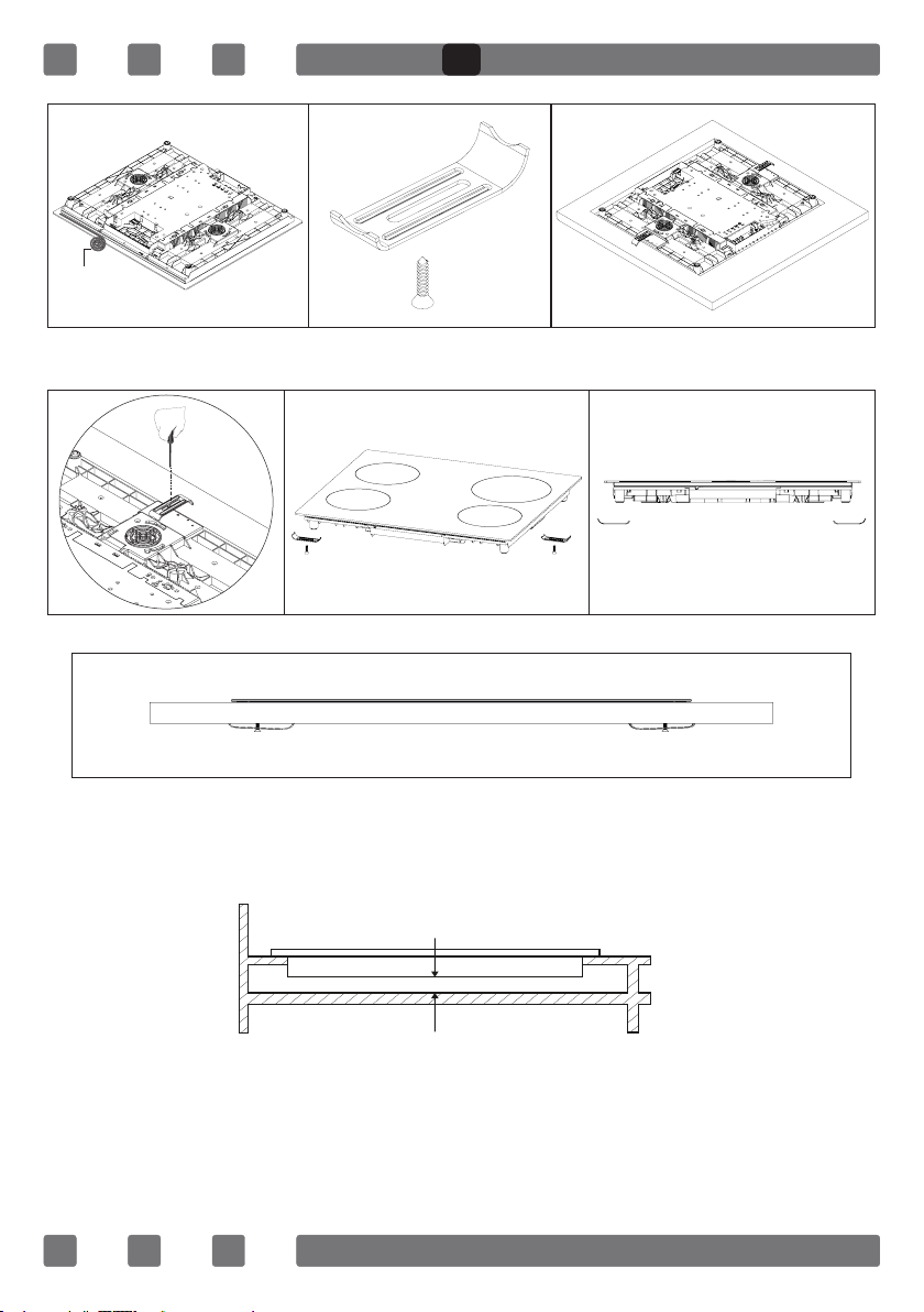
INSTALLATION OF COOKSTOP
1. Detach the burners, burner hoods and grills from the product.
2. Turn the cooktop down and place on smooth ground.
3. In order to prevent entrance of foreign substances and liquids be-
tween cooktop and counter, apply the paste given in package to the sides
of lower guard of counter. For corners, curl paste and increase curls till
lling corner gaps.
4. Turn cooktop again and align with and place on counter.
5. Fasten up your cooktop on counter by using the clamp and screws
supplied.
On the assembly chart given in next page, it is shown how to assemble
your cooktop.
11
Page 12
Roving
GB
Figure 2
6. When product is mounted on a drawer, if it is possible to touch lower
side of product, this section should be separated with a wooden shelf.
min. 30 cm
Figure 3
7. While mounting cooktop on a closet, as shown in the gure above, in
order to separate between closet and cooktop, a shelf should be mounted.
If it is mounted on a built-in oven, there is no need to do that.
8. If your cooktop will be mounted next to right or left wall, the mini-
mum distance between wall and cooktop should be 50 mm.
12
Page 13

GB
COUNTER CUTTING SIZES AND INSTALLATION OF YOUR COOKTOP
Pay attention to the drawings and dimensions given below while making
cooktop installation and adjusting counter cutting sizes.
min. 60 mm
min. 60 mm
520 mm
270 mm
min. 60 mm
Cooktop Of 30cm
520 mm
560 mm
min. 60 mm
Cooktop Of 60cm
300 mm
490 mm
590 mm
490 mm
min. 60 mm
min. 60 mm
min. 60 mm
min. 110 mm
520 mm
270 mm
min. 60 mm
520 mm
560 mm
Cooktop Of 70cm
440 mm
490 mm
min. 60 mm
Cooktop Of 45cm
690 mm
490 mm
min. 60 mm
min. 60 mm
min. 60 mm
520 mm
810 mm
Cooktop Of 90cm
860 mm
490 mm
min. 60 mm
min. 60 mm
13
min. 60 mm
400 mm
960 mm
Cooktop Of 100cm
990 mm
370 mm
min. 60 mm
Page 14
GB
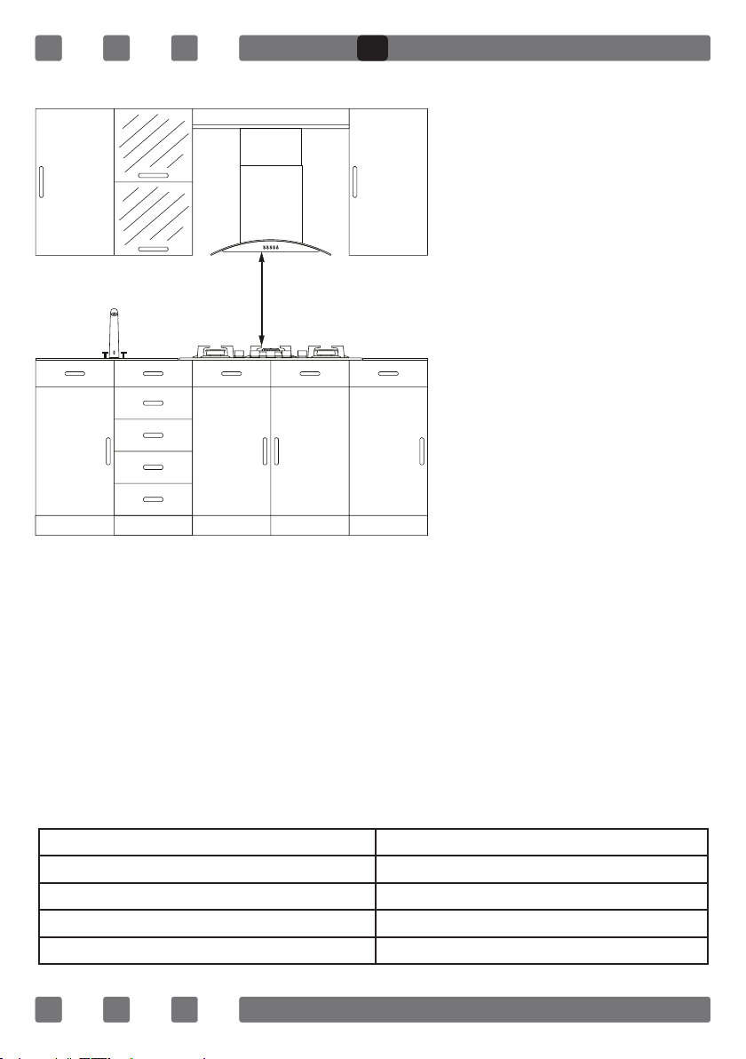
CORRECT PLACE FOR INSTALLATION
Product is designed in
accordance with the kitchen counters supplied from
market. A safe distance
should be left between the
product and kitchen walls
and furniture.
If hood/aspirator will
60 mm min.
be installed over your
appliance, obey to the
recommendation of hood/
aspirator manufacturer for
assembly height. (min. 60
cm)
The gap that cooktop is
to be placed on the counter
should be cut in line with
cooktop installation dimen-
sions.
For installation of the product, the rules specied in local standards
related to electricity should be complied.
VENTILATION OF ROOM
The air needed for burning is received from room air and the gases
emitted are given directly in room. For safe operation of your product,
good room ventilation is a precondition. If no window or room to be
utilized for room ventilation is available, additional ventilation should be
installed. However, room has a door opening outside, it is no needed to
vent holes.
Room Size Ventilating Opening
Smaller than 5m³ min. 100 cm²
Between 5 m³- 10 m³ min. 50 cm²
Bigger than 10m³ no need
In basement or cellar min. 65 cm²
14
Page 15

GB
TRANSFORMATION FROM NATURAL GAS TO LPG AND FROM LPG TO NATURAL GAS
1. Turn off gas and electricity of the cooktop. If your cooktop is hot, wait
for cooling down.
2.For injector change, use a screwdriver whose edge is as the Figure 4.
3. As seen in Figure 5, demount burner lid and burner of the cooktop
and ensure visibility of injector.
4. Remove injector by turning as shown in Figure 6 with screwdriver and
replace it with a new one.
Figure 4 Figure 5 Figure 6
5. After that, detach control switches of the cooktop. Make setting by
turning the screw in the middle of gas cocks with a small screwdriver
in the manner shown in the following picture. To adjust ow rate screw,
use a screwdriver having suitable dimension. For LPG, turn the screw
clockwise. For natural gas, turn the screw one time counter clockwise.
At low position, length of normal ame should be 6-7 mm. For the last
control, check out whether ame is open or closed.
Setting of your appliance may differ according to the type of gas cock
used.
Figure 7 Figure 8
GAS BREAKING SAFETY APPLİANCE (FFD)
Against putting out to be taken place as a
result of liquid overow at upper burners, safety
appliance steps in and cut gas immediately.
15
FFD
Figure 9
Page 16

GB
USAGE OF YOUR COOKTOP
Usage of Gas Cooktop
1. Before starting to use your cooktop, be sure burner hoods are at
correct position. Correct placement of burner hoods are shown in the
following gure.
Figure 10 Figure 11
2. Gas cocks have a special locking mechanism. Therefore, to operate
cooktop zone, press button by pushing ahead and while opening or closing the cock, hold down the button.
Closed Fully open Half open
3. For automatic igniting models, igniting is realized via electricity.
Therefore, before operating appliance, be sure that appliance has electric
connection. Igniting for these models is as follows.
Cooktop cock
is at closed
position.
To ignite cook-
top, rstly press
the button
towards ahead.
While hold-
ing down the
button, lighter
steps in and
starts to
ignition.
By turning the
button right while
holding down,
you can provide
ignition at ame
length you want.
4. Pay attention that cooktop grills are placed on cooktop table com-
pletely. In case of failure about this matter can cause pouring of the materials to be put on that.
16
Page 17

GB
5. For the models having gas putting out safety, following realizing igni-
tion procedure according to the guidelines above, wait for 5-10 seconds
by pushing button ahead without keeping your hands off. Safety mechanism will step in this duration and ensures operation of the cooktop.
With regard to gas putting out appliance, gas cock cuts the gas going to
cooktop zone in case of putting out of cooktop ame due to any reason.
6. While using coffee pot apparatus supplied along with the cooktop, be
sure that foots of apparatus are placed on cooktop grill exactly and remain
on cooktop zone in centred way. Use the apparatus only on small burner.
7. While utilizing gas cooktops, use saucepan, placed on cooktop sur-
face as far as possible. Thanks to that, you can save energy. In the following table, cooking pot diameters recommended to be used as per burners
are given. Characteristic of Wok cooktop zone is to cook quickly.
WOK Burner 24-28cm
Big Burner 22-26cm
Middle Burner 28-22cm
Small Burner 12-18cm
False TrueFalseFalse
Cooking pot to be used with products should have minimum 120 mm. diameter.
Wok Burner
As it possesses double ring ame system, it
gives homogenous heat distribution at the bottom
of cooking pot at high temperature. It is ideal for
short term and high temperature cooking. When
you want to use regular cooking pot on wok burner,
Figure 12
it is necessary that you remove wok cooking pot
carrier from cooktop.
Usage of Hotplate
You can operate electric cooktops by turning the button on control panel
you want to use to the level you desire. Cooktop powers as per levels are
given in the following table.
17
Page 18

GB
LEVEL 1 LEVEL 2 LEVEL 3 LEVEL 4 LEVEL 5 LEVEL 6
80mm
145mm
180mm
145mm Rapid
180mm Rapid
145mm
180mm
145mm Rapid
180mm Rapid
200W 250W 450W --- --- ---
250W 750W 1000W --- --- ---
500W 750W 1500W --- --- ---
500W 1000W 1500W --- --- ---
850W 1150W 2000W --- --- ---
95W 155W 250W 400W 750W 1000W
115W 175W 250W 600W 850W 1500W
135W 165W 250W 500W 750W 1500W
175W 220W 300W 850W 1150W 2000W
MAINTENANCE AND CLEANING
Before starting to maintenance or cleaning, rstly unplug the plug
supplying electricity to cooktop and turn off gas valve. If cooktop is hot,
wait for cooling down.
1. For the purpose that your cooktop has long and economic life, regular
cleaning and maintenance should be performed on your cooktop.
2. Do not clean your cooktop with scratching tools such as bristle brush,
wire wool or knife. Do not use abrasive, scratching, acid materials or detergent.
3. Following mopping parts of your cooktop with soapy cloth, rinse it,
later rinse well with a soft cloth.
4. Clean glass surfaces with special glass cleaning substances. As
scratching of glass surfaces leads to breaking, while cleaning glass surfaces, do not use abrasive cleaners or sharp metal scrapers.
5. Do not clean your cooktop with steamy cleaners.
6. Clean channels and lids of cooktop zones with soapy water and clean
gas channels with a brush.
7. In the course of cleaning your cooktop, never use ammable materi-
als such as acid, thinner and gas.
8. Do not wash plastic and aluminium parts of your cooktop in dish-
washer.
18
Page 19

GB
9.Clean vinegar, lemon, salt, coke and similar acid and alkaline contain-
ing substances poured on your cooktop immediately.
10.In time, cooktop buttons turns hard or never turn any more, in such
circumstances, it may be necessary that buttons are changed. The change
should only be done by authorized service.
Figure 13 Figure 14
Figure 15
TROUBLES AND SOLUTION PROPOSALS
You can solve the troubles you can encounter at your product by checking
the following points before calling technical service.
If cooktop does not operate;
• Check if power cable of cooktop is plugged in
• Examine with safe ways if electric exists on network
• Audit fuses.
• Control whether damage is available on power cable.
• Check if main gas valve in your network is open
• Go through existence of breaking or twisting on gas pipe
• Be sure that gasp pipe is connected to cooktop in appropriate way.
• See over if suitable gas valve is used for your cooktop
(Get periodical maintenance done.)
If starter does not operate;
• be sure that electric power cable of product is plugged in
• clean the edge and body sections of ignition spark plugs found on
burners with a wet and dirt remover materials thoroughly. Be sure that the
channels present on burners are open and clean.
19
Page 20

GB
ENVIRONMENTALLY-FRIENDLY DISPOSAL
1. Dispose of packaging in an environmentally-friendly
manner.
2. This appliance is labelled in accordance with European Directive 2012/19/EU concerning used electrical
and electronic appliances (waste electrical and electronic equipment - WEEE). The guideline determines the
framework for the return and recycling of used appliances as applicable throughout to the EU.
PACKAGE INFORMATION
Packaging materials of the product are manufactured from recyclable
materials in accordance with our National Environment Regulations. Do
not dispose of the packaging materials together with the domestic or
other wastes. Take them to the packaging material collection points designated by the local authorities.
20
Page 21

CZ
Vážený uživateli,
Naším cílem je dodat vám co nejkvalitnější produkt vyrobený v našich
moderních závodech v pečlivém výrobním prostředí, v souladu s konceptem celkové kvality.
Proto vám doporučujeme pozorně si přečíst tento návod k použití, než
výrobek použijete, a uschovat jej pro budoucí využití.
Poznámka: Tento návod k použití je připraven pro více než jeden model. Některé z funkcí popsaných v tomto návodu nemusí být u vašeho
spotřebiče k dispozici.
Všechny naše spotřebiče slouží k domácímu použití, ne ke komerčnímu použití.
"Splňuje směrnici WEEE."
21
Page 22

OBSAH
CZ
Důležitá upozornění
Seznámení se se spotřebičem
Ovládací panel
Nákres elektrického zapojení
Důležitá upozornění
Nastavení plynových varných desek podle typu plynu
Je-li pod varnou deskou vestavěná troub
Instalace varné desky
Velikost výřezu ve skříňce a instalace vaší varné desky
Správné místo k instalaci
Větrání místnosti
Přechod ze zemního plynu na LPG a z LPG na zemní plyn
Plyn - Bezpečnostní zařízení (FFD)
Použití vaší varné desky
Údržba a čištění
Problémy a návrhy řešení
Likvidace šetrná k životnímu prostředí
a informace o balení
23
25
26
26
27
29
30
30
32
33
33
34
34
35
37
38
39
22
Page 23

DŮLEŽITÁ UPOZORNĚNÍ
1. VAROVÁNÍ: Než se dotknete koncovek zapo-
jení, musí být všechny okruhy odpojeny.
2. VAROVÁNÍ: Jakékoli neuvážené vaření s tuky a
oleji může být nebezpečné a může způsobit požár.
3. VAROVÁNÍ: Nebezpečí požáru; na varném pov-
rchu neskladujte žádné potraviny.
4. VAROVÁNÍ: Dosažitelné části se mohou během
použití zahřát. Malé děti udržujte mimo dosah.
5. VAROVÁNÍ: Tento spotřebič a jeho dosažitelné
části se při používání zahřívají.
6. Nastavení stavu tohoto spotřebiče je vyznačeno
na štítku. (nebo na datovém štítku)
7. Tento spotřebič není připojen k systému odvádění
produktů spalování. Tento spotřebič musí být zapojen
a nainstalován v souladu s platnou právní úpravou.
Zvažte požadavky spojené s větráním.
8. Použití plynové plotýnky zvýší vlhkost a množství
spalin v místnosti, kde je spotřebič umístěný. Zejména
během použití spotřebiče se ujistěte, zda je kuchyň
dobře větraná a zachovejte přírodní větrací otvory
nebo nainstalujte mechanický odvětrávací systém. (Digestoř v horní části trouby) Stálé používání spotřebiče
může vyžadovat další odvětrávání. Například, otevření
okna, zvýšení úrovně odvětrávání v mechanickém odvětrávacím systému.
9. VAROVÁNÍ: Spotřebič slouží pouze k vaření.
Nesmí se používat k jiným účelům, například vytápění místnosti.
23
Page 24

10. "Tento spotřebič musí být nainstalovaný v souladu se směrnicemi a pouze na dobře odvětrávaném
místě. Než spotřebič nainstalujete nebo uvedete do
provozu, přečtěte si návod."
11. "Než spotřebič nainstalujete, seznamte se s místními podmínkami (typ plynu a tlak plynu) a ujistěte se,
že nastavení spotřebiče vhodné."
12. "Tyto pokyny platí pro země, jejichž symboly
jsou uvedené na spotřebiči. Pokud symbol země není
na spotřebiči, je třeba, abyste spotřebič přizpůsobili
podmínkám takové země, je třeba, abyste si přečetli
technické pokyny."
13. Systém nespouštějte na dobu delší než na 15
sekund. Pokud se hořák po uplynutí 15 sekund od
spuštění systému nevznítí, otevřete dveře části a /
nebo čekejte minimálně 1 minutu, než hořák zapálíte.
14. K čištění spotřebiče nepoužívejte parní čističe.
15. NIKDY se nepokoušejte hasit požár vodou, ne-
jprve odpojte napájení a potom pomocí, např. pokličky
nebo utěrky, zakryjte požár.
16. Bez stálého dozoru nesmí děti mladší 8 let
spotřebič používat.
17. Dejte pozor, abyste se nedotkli žádných horkých
prvků.
18. Tento spotřebič mohou používat děti starší 8 let
a osoby se sníženými fyzickými, senzorickými nebo
mentálními schopnostmi nebo bez dostatku zkušeností a znalostí v případě, že mají dozor nebo jsou instruovány ohledně bezpečného použití zařízení a budou obeznámeny se souvisejícími nebezpečími.
24
Page 25

CZ
SEZNÁMENÍ SE SE SPOTŘEBIČEM
1
3
4 5 6 7
2
1- Pozice hořáku
2 - Skleněný nebo kovový povrch
3 - Ovládací tlačítka
4 - Malý hořák
5 - Střední hořák
6 - Velký hořák
8
11
9 10
12
7 - Hořák Wok
8 - Varná deska
9 - Adaptér na kávovar
10 - Adaptér na hořák Wok
11 - Litá mřížka
12 - Smaltovaná mřížka
25
Page 26

OVLÁDACÍ PANEL
Panel - varná plocha 70-90 cm a 100 cm
CZ
Panel - varná plocha 60 cm
Panel - varná plocha 45 cm
NÁKRES ELEKTRICKÉHO ZAPOJENÍ
Elektrické zapojení spotřebiče v souladu s následujícím nákresem nechte
provést autorizovanou osobu.
220-240V~50/60Hz
L1
H05 VV-F 3G 1,5 mm²
Neutrální
Neutr.
Uzemnění
Terre
Erdung
26
Page 27

CZ
DŮLEŽITÁ UPOZORNĚNÍ
Elektrické zapojení a bezpečnost
1.Nastavení stavu tohoto spotřebiče je vyznačeno na štítku.
2.Tento spotřebič není připojen k žádnému zařízení na uvolňování produktů
spalování. Musí být zapojen a nainstalován v souladu s platnou směrnicí pro
montáž.
3.Velkou pozornost je třeba věnovat podmínkám souvisejícím s větráním.
4.Váš spotřebič musí být připojený k pojistce odpovídající elektrickému výkonu.
V případě potřeby se doporučuje, aby zapojení provedl autorizovaný servis.
5.Váš spotřebič je kongurován v souladu s napájením 220-240V AC/380415V3N AC 50/60Hz.
6.Pokud se napájení od těchto hodnot liší, kontaktujte autorizovaný servis,
prosím.
7.Elektrické zapojení vašeho spotřebiče smí být provedeno pouze do pojistek
s vhodně zapojeným uzemněním. Není-li na místě, kde má být spotřebič nainstalován, k dispozici žádná vhodná pojistka, okamžitě kontaktujte autorizovaný
servis. Výrobce nezodpovídá za škody způsobené připojenou pojistkou bez
provedeného uzemnění.
8.Zástrčka spotřebiče musí být co nejblíže uzemněné pojistce, bez použití
prodlužovacího kabelu.
9.Nedovolte, aby napájecí kabel spotřebiče přišel do kontaktu s horkými částmi spotřebiče. Stejně tak nedovolte jeho kontakt s ostrými hranami a rohy.
10.Je-li napájecí kabel poškozený, musí být vyměněn buď výrobcem nebo
zástupcem jeho servisu nebo obdobně kvalikovanou osobou, aby se tak
předešlo nebezpečným situacím.
11.Špatné elektrické zapojení může spotřebič poškodit. V takovém případě
se na váš spotřebič nebude vztahovat žádná záruka. Elektrické zapojení vašeho spotřebič musí provést autorizovaný servis.
12.Při provozu varné desky se mohou některé části zahřát. I když spínače
přepnete do zavřené polohy, tyto části zůstanou horké ještě chvíli. Děti musí
být neustále udržovány mimo a nesmí být ponechány bez dozoru. Povrchu varné desky se nedotýkejte pokud blikají výstražné kontrolky. Když spotřebič vypnete, horké části, které jsou i nadále nebezpečné, jsou označeny výstražnými
kontrolkami. (sklokeramické modely).
27
Page 28

Zapojení plynu a bezpečnost
CZ
1. Pro zapojení LPG (láhev na plyn) připevněte kovovou svorku na hadici vycházející z
LPG (láhev na plyn). Okraj hadice připevněte
ke konektoru hadice za spotřebičem, zatlačte
na konec hadic, který jste ohřáli v horké vodě.
Hlavní plynové
potrubí
Těsnění
Konektor hadice
Poté svorku připevněte na konec hadice a
utáhněte ji šroubovákem. Těsnění a konektor
Kovová svorka
hadice nutný k zapojení jsou znázorněné na
obrázku níže.
Hadice pro připojení LPG
POZNÁMKA: Regulátor, který bude připevněn na LPG (láhev na plyn), musí
mít funkci 300 mmSS.
2. Zapojení zemního plynu musí provést
Hlavní plynové
potrubí
Těsnění
Matice
Hadice pro připojení zemního
plynu
autorizovaný servis. Při zapojení zemního
plynu dejte do matice na okraji hadice pro
připojení zemního plynu těsnění. Abyste
hadici připevnili na přívod plynu, otočte
maticí. Zapojení dokončete kontrolou úniku
plynu.
Zapojení plynové hadice a elektrické zapojení spotřebiče
nesmí vést v blízkosti horkých ploch, např. v zadní části
spotřebiče. Plynová hadice musí být připojena v širokém úhlu,
aby se předešlo možnosti jejího zlomení. Pohyb spotřebiče
připojeného k přívodu plynu může způsobit únik plynu.
Pravda Lež Pravda Pravda
28
Page 29

CZ
3. Spotřebič připojte k plynovému kohoutu v co nejkratší vzdálenosti tak, aby-
ste předešli jakémukoli úniku plynu. Z bezpečnostních důvodů musí být použitá
hadice dlouhá maximálně 125 cm, minimálně 40 cm.
4. Během provádění kontroly úniku plynu nikdy nepoužívejte zapalovač,
zápalky, hořící cigaretu nebo podobnou hořlavou látku.
5. Na spoj naneste mýdlo. V případě existence úniku se v postižené oblasti
objeví pěna.
6. Má-li být varná deska namontovaná do skříně nebo otevírací zásuvky, je
třeba nad varnou desku namontovat ochranný panel s minimálně 15 mm otvorem.
NASTAVENÍ PLYNOVÝCH VARNÝCH DESEK PODLE TYPU PLYNU
Typ plynu (LPG nebo zemní plyn), pro který je váš spotřebič vyrobený, je
uvedený na štítku v zadní části produktu, společně s technickými funkcemi.
Není-li nastavení plynu ve spotřebiči stejné jako nastavení plynu ve vaší síti,
musí být upraveno odborníkem. V následující tabulce jsou uvedeny hodnoty
vstřikovače, průtoku plynu a výkonu spotřebiče, podle typu plynu.
Velký
hořák
Hořák
Wok
Střední
hořák
Malý
hořák
LPG (láhev na plyn)
G30-30 mbar
Vstřikovač mm 0,85 mm 1,15
Průtok plynu g/h 198 g/h 0,263
Výkon kW 2,75 kW 2,75
Vstřikovač mm 0,96 mm 1,30
Průtok plynu g/h 259,20 g/h 0,300
Výkon kW 3,60 kW 3,35
Vstřikovač mm 0,65 mm 0,97
Průtok plynu g/h 115,20 g/h 0,165
Výkon kW 1,60 kW 1,70
Vstřikovač mm 0,50 mm 0,72
Průtok plynu g/h 64,80 g/h 0,086
Výkon kW 0,90 kW 0,90
Zemní plyn
G20-20 mbar
29
Page 30

CZ
JE-LI POD VARNOU DESKOU UMÍSTĚNA VESTAVĚNÁ TROUBA;
Varná deska
Hadice
Plynové potrubí musí být
zapojeno tak, aby se nedotýkalo trouby dole, ostrých
hran a rohů, ani nesmí být
Trouba
nataženo tak, aby se ohýbalo nebo deformovalo. Zapojení plynu proveďte z pravé
části varné plochy, hadici
Obrázek 1
uchyťte pomocí svorky.
INSTALACE VARNÉ DESKY
1. Z produktu sejměte hořáky, kryty hořáků a grily.
2. Varnou desku otočte směrem dolů a položte na rovnou plochu.
3. Aby se předešlo vniknutí cizích látek a kapalin mezi varnou desku a přepáž-
ku, naneste na spodní strany přepážky pastu, která je součástí balení. V rozích
pastu nahrňte a vyplňte mezery v rozích.
4. Varnou desku znovu otočte a usaďte do přepážky.
5. Varnou desku v přepážce utáhněte pomocí dodané svorky a šroubů.
Na další straně je znázorněno provedení montáže varné desky.
30
Page 31

Provazec
CZ
Obrázek 2
6. V případě, že je produkt namontován do zásuvky, je-li možné dotknout se
spodní strany produktu, tato část musí být oddělena dřevěnou deskou.
min. 30 cm
Obrázek 3
7. Při montáži varné desky na skříň, jak je znázorněno na obrázku výše, je
třeba namontovat polici, která oddělí skříň a varnou desku. Je-li montovaná na
vestavěnou troubu, není to třeba.
8. Bude-li vaše varná deska namontovaná vedle levé nebo pravé stěny, min-
imální vzdálenost mezi stěnou a varnou deskou musí být 50 mm.
31
Page 32

CZ
VELIKOST VÝŘEZU VE SKŘÍŇCE A INSTALACE VAŠÍ VARNÉ DESKY
Při instalaci a nastavení výřezu ve skříňce věnujte pozornost níže zobra-
zeným nákresům a rozměrům.
min. 60 mm
min. 60 mm
520 mm
270 mm
min. 60 mm
Varná plocha 30 cm
520 mm
560 mm
min. 60 mm
Varná plocha 60 cm
300 mm
490 mm
590 mm
490 mm
min. 60 mm
min. 60 mm
min. 60 mm
min. 110 mm
520 mm
270 mm
min. 60 mm
Varná plocha 45 cm
520 mm
560 mm
Varná plocha 70 cm
440 mm
490 mm
690 mm
490 mm
min. 60 mm
min. 60 mm
min. 60 mm
min. 60 mm
520 mm
810 mm
Varná plocha 90 cm
860 mm
490 mm
min. 60 mm
min. 60 mm
32
min. 60 mm
400 mm
960 mm
Varná plocha 100 cm
990 mm
370 mm
min. 60 mm
Page 33

CZ
SPRÁVNÉ MÍSTO K INSTALACI
Produkt je navržen v
souladu s kuchyňskými
skříňkami na trhu. Mezi
produktem a stěnami a
nábytkem musí být ponechána bezpečná vzdálenost.
Bude-li nad vaším
spotřebičem nainstalovaná
min. 60 mm
kovaná v místních směrnicích pro elektrické spotřebiče.
digestoř, řiďte se doporučeními výrobce digestoře
pro výšku montáže. (min. 60
cm)
Prostor, do kterého bude
varná deska vložena, musí
být vyřezán v souladu s pokyny pro rozměry.
Při instalaci produktu musí
být dodržena pravidla speci-
VĚTRÁNÍ MÍSTNOSTI
Vzduch nutný k hoření se získává ze vzduchu v místnosti a spalované plyny se uvolňují přímo do místnosti. Předpokladem bezpečného provozu vašeho produktu je dobré větrání místnosti. Není-li k dispozici žádné okno nebo
v místnosti nelze zajistit větrání, je třeba nainstalovat doplňkovou ventilaci.
Nicméně, v místnosti s dveřmi ven není třeba žádný větracích otvorů.
Velikost místnosti Větrací otvor
Menší než 5m³ min. 100 cm²
Mezi 5 m³- 10 m³ min. 50 cm²
Větší než 10m³ není třeba
Ve sklepě nebo přízemí min. 65 cm²
33
Page 34

CZ
PŘECHOD ZE ZEMNÍHO PLYNU NA LPG A Z LPG NA ZEMNÍ PLYN
1. Vypněte přívod plynu a elektřiny do varné desky. Je-li vaše varná deska
horká, nechte ji vychladnout.
2.Ke změně vstřikovače použijte šroubovák, jehož okraj je na Obr. 4.
3. Jak je znázorněno na Obr. 5, z varné desky demontujte víko hořáku a
hořák a zajistěte viditelnost vstřikovače.
4. Vstřikovač sejměte otáčením zobrazeným na Obr. 6 a nahraďte ho za nový.
Obrázek 4 Obrázek 5 Obrázek 6
5. Potom odpojte ovládací prvky varné desky. Proveďte nastavení otočením
šroubu uprostřed plynových kohoutů pomocí malého šroubováku tak, jak
je to znázorněno na následujícím obrázku. Pro nastavení šroubu použijte
šroubovák odpovídajících rozměrů. U LPG otočte šroub ve směru hodinových
ručiček. U zemního plynu otočte šroub proti směru hodinových ručiček. V
nízké pozici je délka normálního plamene 6-7 mm. Při poslední kontrole zkontrolujte, zda je plamen otevřený nebo zavřený.
Nastavení vašeho spotřebiče se může lišit podle použitého typu plynového
kohoutu.
Obrázek 7 Obrázek 8
PLYN - BEZPEČNOSTNÍ ZAŘÍZENÍ (FFD)
Pokud dojde k přetečení potravin na horní hořáky,
bezpečnostní zařízení se sepne a okamžitě odpojí
plyn.
34
FFD
Obrázek 9
Page 35

CZ
POUŽITÍ VAŠÍ VARNÉ DESKY
Použití plynové varné desky
1. Než začnete varnou desku používat, zkontrolujte, zda jsou hořáky ve
správné pozici. Správné umístění hořáků je znázorněno na následujícím obrázku.
Obrázek 10
Obrázek 11
2. Plynové kohouty mají speciální uzamykací mechanismus. Proto při ov-
ládání zóny varné desky zatlačte na tlačítko a během otevírání nebo zavírání
kohoutu ho přidržte.
Zavřeno Plně otevřeno Z části otevřeno
3. U modelů s automatickým zapalováním se zapalování provádí pomocí ele-
ktřiny. Proto se před spuštěním spotřebiče ujistěte, zda má spotřebič elektrické
zapojení. Zapalování těchto model je následující.
Kohout varné
desky je v uza-
vřené pozici.
Chcete-li
varnou desku
zapálit, nejprve
tlačítko stlačte.
Zatímco držíte
tlačítko, spustí
se zapalovač
a zahájí zapalo-
vání.
Přidržením a
otočením tlačítka
doprava můžete
nastavit poža-
dovanou délku
plamene.
4. Věnujte pozornost tomu, zda jsou mřížky varné desky na varné desce
umístěny správně. V případě, že tomu tak není, může dojít k rozlití věcí, které
na ně budou umístěny.
35
Page 36

CZ
5. U modelů s vyvedeným plynem dodržte postup zapalování, který odpovídá
pokynům výše, počkejte 5-10 sekund a stiskněte tlačítko, aniž byste své ruce
sundali. Bezpečnostní mechanismus přejde do tohoto trvání a zajistí provoz
varné desky. S ohledem na plyn vyvedený do spotřebič plynový kohout odpojí
plyn vstupující do zóny varné desky v případě, že plamen z nějakého důvodu
zhasnul.
6. Při používání konvičky na kávu dodávané s varnou deskou se ujistěte, zda
jsou nožičky tohoto zařízení umístěny na mřížce varné desky přesně a zda
jsou v zóně varné desky vycentrované. Zařízení používejte pouze na malém
hořáku.
7. Při používání plynových varných desek používejte pánev, umístěnou na
povrch varné desky co nejdále. Díky tomu šetříte energii. V následující tabulce
jsou uvedeny průměry hrnců, které lze použít na uvedené hořáky. Zóna varné
desky Wok dokáže jídlo uvařit rychle.
Hořák WOK 24-28 cm
Velký hořák 22-26 cm
Prostřední hořák 28-22 cm
Malý hořák 12-18 cm
Hořák Wok
Obrázek 12
Lež
LežLež
Pravda
Nádobí musí mít minimální průměr 120 mm.
Vzhledem k tomu, že je vybavený systémem dvojitého hořáku, zajišťuje homogenní distribuci tepla ve
spodní části pánve. Je to ideální pro krátkodobé vaření
při vysokých teplotách. Chcete-li na hořáku wok použít
běžné nádobí, je třeba, abyste z varné desky sejmuli
mřížku wok.
36
Page 37

CZ
POUŽITÍ VARNÉ DESKY
Elektrické varné desky můžete ovládat otáčením tlačítek na ovládacím panelu a nastavit tak požadovanou úroveň. Výkony varné desky podle úrovní jsou
uvedeny v následující tabulce.
ÚROVEŇ 1ÚROVEŇ 2ÚROVEŇ 3ÚROVEŇ 4ÚROVEŇ 5ÚROVEŇ
6
80 mm
145 mm
180 mm
145 mm rychlý
180 mm rychlý
145 mm
180 mm
145 mm rychlý
180 mm rychlý
ÚDRŽBA A ČIŠTĚNÍ
Než začnete provádět údržbu nebo čištění, nejprve odpojte přívod elektřiny
a vypněte přívod plynu. Je-li varná deska horká, nechte ji vychladnout.
1. Aby vaše varná deska měla dlouhou a ekonomickou životnost, je třeba
provádět pravidelné čištění a údržbu vaší varné desky.
2. Varnou desku nečistěte ostrými nástroji, např. drátěnkou nebo nožem. Ne-
používejte abrazivní, drsné, kyselé materiály nebo čisticí přípravky.
3. Po otření varné desky navlhčeným hadříkem desku důkladně vysušte měk-
kým hadříkem.
4. Skleněné povrchy vyčistěte speciálním čisticím přípravkem na sklo. Vzhle-
dem k tomu, že poškrábání skleněných povrchů vede k jejich nalomení, při
čištění skleněných povrchů nepoužívejte abrazivní čisticí přípravky nebo ostré
kovové škrabky.
5. Varnou desku nečistěte parními čističi.
6. Kanály a víka zón varné desky čistěte vodou a plynové kanály kartáčem.
7. Během čištění vaší varné desky nikdy nepoužívejte hořlavé materiály, např.
ředidla, kyseliny a benzín.
8. Plastové a hliníkové části vaší varné desky nemyjte v myčce na nádobí.
200W 250W 450W --- --- ---
250W 750W 1000W --- --- --500W 750W 1500W --- --- --500W 1000W 1500W --- --- --850W 1150W 2000W --- --- ---
95W 155W 250W 400W 750W 1000W
115W 175W 250W 600W 850W 1500W
135W 165W 250W 500W 750W 1500W
175W 220W 300W 850W 1150W 2000W
37
Page 38

CZ
9.K čištění použijte vinný ocet, citrón, sůl, coca-colu a podobné látky obsahu-
jící kyseliny a zásadité látky, které nalijete přímo na svoji varnou desku.
10.V průběhu času tlačítka varné desky ztvrdnou nebo se přestanou otáčet, v
takovém případě bude třeba tato tlačítka vyměnit. Výměnu smí provádět pouze
autorizovaný servis.
Obrázek 13 Obrázek 14
PROBLÉMY A NÁVRHY ŘEŠENÍ
Problémy, ke kterým u vašeho produktu dojde, můžete vyřešit ještě než
kontaktujete technický servis, zkontrolováním následujících bodů.
Pokud varná deska nefunguje;
• Zkontrolujte, zda je napájecí kabel varné desky zapojený
• Bezpečně zkontrolujte, zda je elektřina stále v síti.
• Zkontrolujte pojistky.
• Zkontrolujte, zda nedošlo k poškození napájecího kabelu.
• Zkontrolujte, zda je hlavní plynový ventil otevřený.
• Zkontrolujte, zda nedošlo ke zlomení nebo protočení plynového potrubí.
• Zkontrolujte, zda je plynové potrubí k varné desce připojeno správným
způsobem.
• Zkontrolujte, zda je na vaší varné desce použitý vhodný plynový ventil.
(Proveďte pravidelnou údržbu.)
Pokud nefunguje spouštěcí zařízení;
• Zkontrolujte, zda je zapojený napájecí kabel produktu.
• Důkladně vyčistěte hranu a části zapalování na hořácích pomocí od-
straňovače nečistot. Zkontrolujte, zda jsou kanály na hořácích otevřené a čisté.
Obrázek 15
38
Page 39

CZ
EKOLOGICKÁ LIKVIDACE
1. Obal zlikvidujte způsobem šetrným k životnímu prostředí.
2. Tento spotřebič je označen v souladu s evropskou směrni-
cí 2012/19/EU týkající se použitých elektrických a elektronických spotřebičů (elektrický a elektronický odpad – WEEE).
Směrnice stanoví rámec pro vrácení a recyklaci použitých
spotřebičů, který platí po celé EU.
INFORMACE O BALENÍ
Balící materiály jsou vyrobeny z recyklovatelných materiálů v souladu s našimi národními směrnicemi na ochranu životního prostředí. Nelikvidujte obalové
materiály společně s domácím nebo jiným odpadem. Odvezte je do míst sběrného odpadu určených místními úřady.
39
Page 40

SK
Vážený používateľ,
Naším cieľom je zveriť vám čo najkvalitnejší produkt vyrobený v našich
moderných závodoch v starostlivom výrobnom prostredí, v súlade s
konceptom celkovej kvality.
Preto vám odporúčame pozorne si prečítať tento návod na použitie, skôr
než výrobok použijete, a uschovať ho na budúce využitie.
Poznámka: Tento návod na použitie je pripravený pre viac ako jeden
model. Niektoré z funkcií popísaných v tomto návode nemusia byť pri vašom
spotrebiči k dispozícii.
Všetky naše spotrebiče slúžia na domáce použitie, nie na komerčné
použitie.
"Spĺňa smernicu
WEEE."
40
Page 41

SK
OBSAH
Dôležité upozornenia___________________________________ 42
Zoznámenie sa so spotrebičom___________________________ 43
Ovládací panel________________________________________ 45
Nákres elektrického zapojenia____________________________ 45
Dôležité upozornenia___________________________________ 46
Nastavenie plynových varných dosiek podľa typu plynu _______ 48
Ak je pod varnou doskou vstavaná rúra____________________ 49
Inštalácia varnej dosky_________________________________ 49
Veľkosť výrezu v skrinke a inštalácia vašej varnej dosky_______ 51
Správne miesto na inštaláciu____________________________ 52
Vetranie miestnosti____________________________________ 52
Prechod zo zemného plynu na LPG a z LPG na zemný plyn ____ 53
Plyn - Bezpečnostné zariadenie (FFD)_____________________ 53
Použitie vašej varnej dosky______________________________ 54
Údržba a čistenie_____________________________________ 56
Problémy a návrhy riešenia_____________________________ 57
Likvidácia šetrná k životnému prostrediu
a informácie o balení _________________________________ 58
41
Page 42

DÔLEŽITÉ UPOZORNENIA
1.
VAROVANIE: Skôr než sa dotknete koncoviek zapojenia,
musia byť všetky okruhy odpojené.
2. VAROVANIE: Akékoľvek neuvážené varenie s tukmi a
olejmi môže byť nebezpečné a môže spôsobiť požiar.
3. VAROVANIE: Nebezpečenstvo požiaru; na varnom povrchu
neskladujte žiadne potraviny.
4. VAROVANIE: Dosiahnuteľné časti sa môžu počas
použitia zahriať. Malé deti udržujte mimo ich dosahu.
5. VAROVANIE: Tento spotrebič a jeho dosiahnuteľné
časti sa pri používaní zahrievajú.
6. Nastavenie stavu tohto spotrebiča je vyznačené
na štítku. (alebo na údajovom štítku)
7. Tento spotrebič nie je pripojený k systému odvádzania
produktov spaľovania. Tento spotrebič musí byť zapojený a
nainštalovaný v súlade s platnou právnou úpravou. Zvážte
požiadavky spojené s vetraním.
8. Použitie plynovej platničky zvýši vlhkosť a množstvo
spalín v miestnosti, kde je spotrebič umiestnený. Najmä
počas používania spotrebiča sa uistite, či je kuchyňa
dobre vetraná a zachovajte prirodzené vetracie otvory
alebo nainštalujte mechanický odvetrávací systém. (digestor v
hornej časti rúry). Stále používanie spotrebiča
môže vyžadovať ďalšie odvetrávanie. Napríklad, otvorenie okien,
zvýšenie úrovne odvetrávania v mechanickom odvetrávacom
systéme.
9. VAROVANIE: Spotrebič slúži iba na varenie.
Nesmie sa používať na iné účely, napríklad na vykurovanie
miestnosti.23
Page 43

10.
Tento spotrebič musí byť nainštalovaný v súlade so smernicami
a len na dobre vetranom mieste. Skôr než spotrebič nainštalujete
alebo uvediete do prevádzky, prečítajte si návod.
11. Skôr než spotrebič nainštalujete, zoznámte sa s miestnymi
podmienkami (typ plynu a tlak plynu) a uistite sa,
že nastavenie spotrebiča je vhodné.
12. Tieto pokyny platia pre krajiny, ktorých symboly
sú uvedené na spotrebiči. Ak symbol krajiny nie je
na spotrebiči, je potrebné, aby ste spotrebič prispôsobili
podmienkam takej krajiny, je tiež potrebné, aby ste si prečítali
technické pokyny.
13. Systém nespúšťajte po dobu dlhšiu než 15
sekúnd. Ak sa horák po uplynutí 15 sekúnd od
spustenia systému nevznieti, otvorte dvere časti a/alebo počkajte
aspoň 1 minútu, než horák zapálite.
14. Na čistenie spotrebiča nepoužívajte parné čističe.
15. NIKDY sa nepokúšajte hasiť požiar vodou, najprv odpojte
napájanie a potom pomocou, napr. pokrievky
alebo utierky, zakryte požiar.
16. Bez stáleho dozoru nesmú deti mladšie ako 8 rokov
používať spotrebič.
17. Dajte pozor, aby ste sa nedotkli žiadnych horúcich
prvkov.
18. Tento spotrebič môžu používať deti staršie ako 8 rokov
a osoby so zníženými fyzickými, senzorickými alebo
mentálnymi schopnosťami alebo bez dostatku skúseností a
zručností iba v prípade, že majú dozor alebo sú in-
skonštruované ohľadom bezpečného použitia zariadenia a budú
oboznámené so súvisiacimi rizikami.
24
Page 44

SK
ZOZNÁMENIE SA SO SPOTREBIČOM
1
2
3
4 5 6
7
8 9
10
11
1- Pozícia horáka
2 - Sklenený alebo kovový povrch
3 - Ovládacie tlačidlá
4 - Malý horák
5 - Stredný horák
6 - Veľký horák
44
12
Horák Wok
8 - Varná doska
9 - Adaptér na kávovar
10 - Adaptér na horák Wok
11 - Liata mriežka
12 - Smaltovaná mriežka
Page 45

SK
OVLÁDACÍ PANEL
Panel - varná plocha 70-90 cm a 100 cm
Panel - varná plocha 60 cm
Panel - varná plocha 45 cm
NÁKRES ELEKTRICKÉHO ZAPOJENIA
Elektrické zapojenie spotrebiča v súlade s nasledujúcim nákresom nechajte
vykonať autorizovanou osobu.
220-240V~50/60Hz
L1
Neutrálne
Neutr.
Uzemnenie
Terre
Erdung
H05 VV-F 3G 1,5 mm²
45
Page 46

SK
DÔLEŽITÉ UPOZORNENIA
Elektrické zapojenie a bezpečnosť
1.
Nastavenie stavu tohto spotrebiča je vyznačené na štítku.
2.Tento spotrebič nie je pripojený na žiadne zariadenie slúžiace na uvoľňovanie
produktov spaľovanie. Musí byť zapojený a nainštalovaný v súlade s platnou
smernicou na montáž.
3.Veľkú pozornosť treba venovať podmienkam súvisiacim s vetraním.
4.Váš spotrebič musí byť pripojený k poistke zodpovedajúcej elektrickému výkonu.
V prípade potreby sa odporúča, aby zapojenie vykonal autorizovaný servis.
5.Váš spotrebič je nakonfigurovaný v súlade s napájaním 220-240V AC/380-
415V3N AC 50/60Hz.
6.Ak je napájanie odlišné od týchto hodnôt, kontaktujte autorizovaný servis,
prosím.
7.Elektrické zapojenie vášho spotrebiča môže vykonať len do poistiek
s vhodne zapojeným uzemnením. Ak nie je na mieste, kde má byť spotrebič
nainštalovaný, k dispozícii žiadna vhodná poistka, okamžite kontaktujte
autorizovaný servis. Výrobca nezodpovedá za škody spôsobené pripojenou
poistkou bez vykonaného uzemnenia.
8.Zástrčka spotrebiča musí byť čo najbližšie k uzemnenej poistke, bez použitia
predlžovacieho kábla.
9.Nedovoľte, aby napájací kábel spotrebiča prišiel do kontaktu s horúcimi časťami
spotrebiča. Rovnako tak nedovoľte jeho kontaktu s ostrými hranami a rohmi.
10.Ak je napájací kábel poškodený, musí byť vymenený buď výrobcom alebo
zástupcom jeho servisu alebo obdobne kvalifikovanou osobou, aby sa tak
predišlo nebezpečným situáciám.
11.Nesprávne elektrické zapojenie môže spotrebič poškodiť. V takom prípade
sa na váš spotrebič nebude vzťahovať žiadna záruka. Elektrické zapojenie vášho
spotrebiča musí vykonať autorizovaný servis.
12.Pri prevádzke varnej dosky sa môžu niektoré časti zahriať. Aj keď spínače
prepnete do zatvorenej polohy, tieto časti zostanú horúce ešte chvíľu. Deti musia
byť neustále udržiavané mimo a nesmú byť ponechané bez dozoru. Povrchu varnej dosky sa nedotýkajte kým blikajú výstražné kontrolky. Keď spotrebič vypnete, horúce časti, ktoré sú aj naďalej nebezpečné, sú označené výstražnými
kontrolkami. (Sklokeramické modely).
46
Page 47

SK
Zapojenie plynu a bezpečnosť
1.
Pre zapojenie LPG (fľaša na plyn) pripevnite kovovú
svorku na hadicu vychádzajúce z
LPG (fľaša na plyn). Okraj hadice pripevnite
ku konektoru hadice za spotrebičom, zatlačte
na koniec hadíc, ktorý ste ohriali v horúcej vode.
Potom svorku pripevnite na koniec hadice a
utiahnite ju skrutkovačom. Tesnenie a konektor
hadice nutný k zapojenia sú znázornené na
obrázku nižšie.
Hlavné plynové
potrubie
Tesnenie
Konektor hadice
Kovová svorka
Hadica na pripojenie LPG
POZNÁMKA:
Regulátor, ktorý bude pripevnený na LPG (fľaša na plyn), musí
mať funkciu 300 mmSS.
Hlavné plynové
potrubie
Tesnenie
Matice
Hadica na pripojenie zemného
plynu
2.
Zapojenie zemného plynu musí vykonať
autorizovaný servis. Pri zapojení zemného
plynu dajte do matice na okraji hadice na
pripojenie zemného plynu tesnenie. Aby ste
hadicu pripevnili na prívod plynu, otočte
maticou. Zapojenie dokončite kontrolou úniku
plynu.
Zapojenie plynovej hadice a elektrické zapojenie spotrebiča
nesmie viesť v blízkosti horúcich plôch, napr. v zadnej časti
spotrebiča. Plynová hadica musí byť pripojená v širokom uhle,
aby sa predišlo možnosti jej zlomenia. Pohyb spotrebiča
pripojeného k prívodu plynu môže spôsobiť únik plynu.
Správne
Nesprávne
Správne
Správne
8
Page 48

SK
3.
Spotrebič pripojte k plynovému kohútiku v čo najkratšej vzdialenosti tak, aby
ste predišli akémukoľvek úniku plynu. Z bezpečnostných dôvodov musí byť použitá
hadica dlhá maximálne 125 cm, minimálne 40 cm.
4. Počas vykonávania kontroly úniku plynu nikdy nepoužívajte zapaľovač,
zápalky, horiacu cigaretu alebo podobnú horľavú látku.
5. Na spoj naneste mydlo. V prípade existencie úniku sa v postihnutej oblasti
objaví pena.
6. Ak má byť varná doska namontovaná do skrine alebo otváracej zásuvky, je
potrebné nad varnú dosku namontovať ochranný panel s minimálne 15 mm
otvorom.
NASTAVENIE PLYNOVÝCH VARNÝCH DOSIEK PODĽA TYPU PLYNU
Typ plynu (LPG alebo zemný plyn), pre ktorý je váš spotrebič vyrobený, je
uvedený na štítku v zadnej časti produktu, spolu s technickými funkciami.
Ak nie je nastavenie plynu v spotrebiči rovnaké ako nastavenie plynu vo vašej sieti,
musí byť upravené odborníkom. V nasledujúcej tabuľke sú uvedené hodnoty
LPG (fľaša na plyn)
G30-30 mbar
Zemný plyn
G20-20 mbar
Veľký
horák
Vstrekovač
mm
0,85
mm
1,15
Prietok plynu
g/h
198
g/h
0,263
Výkon
kW
2,75
kW
2,75
Horák
Wok
Vstrekovač
mm
0,96
mm
1,30
Prietok plynu
g/h
259,20
g/h
0,300
Výkon
kW
3,60
kW
3,35
Stredný
horák
Vstrekovač
mm
0,65
mm
0,97
Prietok plynu
g/h
115,20
g/h
0,165
Výkon
kW
1,60
kW
1,70
Malý
horák
Vstrekovač
mm
0,50
mm
0,72
Prietok plynu
g/h
64,80
g/h
0,086
Výkon
kW
0,90
kW
0,90
Page 49

SK
AK JE POD VARNOU DOSKOU UMIESTNENÁ VSTAVANÁ RÚRA;
Obrázek 1
Varná deska
Hadice
Trouba
Plynové potrubie musí byť
zapojené tak, aby sa ne-
dotklo rúry dole, ostrých
hrán a rohov, ani nesmie byť
natiahnuté tak, aby sa ohýba-
lo alebo deformovalo. Zapojenie plynu vykonajte z pravej
časti varnej plochy, hadicu
uchyťte pomocou svorky.
INŠTALÁCIA VARNEJ DOSKY
1.
Z produktu odstráňte horáky, kryty horákov a grily.
2. Varnú dosku otočte smerom nadol a položte na rovnú plochu.
3. Aby sa predišlo vniknutiu cudzích látok a kvapalín medzi varnú dosku a prepáž-
ku, naneste na spodnú stranu prepážky pastu, ktorá je súčasťou balenia. V rohoch
pastu nahrňte a vyplňte medzery v rohoch.
4. Varnú dosku znovu otočte a usaďte do prepážky.
5. Varný panel v prepážke utiahnite pomocou dodanej svorky a skrutiek.
Na ďalšej strane je znázornené vykonanie montáže varnej dosky.
49
Page 50

SK
Povrazec
Obrázok 2
6.
V prípade, ak je produkt namontovaný do zásuvky a ak je možné dotknúť sa
spodnej strany produktu, táto časť musí byť oddelená drevenou doskou.
min. 30 cm
Obrázok 3
7.
Pri montáži varnej dosky na skriňu, ako je znázornené na obrázku vyššie, je
potrebné namontovať policu, ktorá oddelí skriňu a varnú dosku. Ak je montovaná
na vstavanú rúru, nie je to potrebné.
8. Ak bude vaša varná doska namontovaná vedľa ľavej alebo pravej steny,
minimálna vzdialenosť medzi stenou a panelom musí byť 50 mm.
50
Page 51

SK
VEĽKOSŤ VÝREZU V SKRINKE A INŠTALÁCIA VAŠEJ VARNEJ DOSKY
Pri inštalácii a nastavení výrezu v skrinke venujte pozornosť nižšie
zobra-
r
300 m
0 mm
m
52
min. 60 mm
m
min. 60 mm
270 mm
490 m
min. 60 mm
Varná plocha 30 cm
520 mm
440 mm
min. 60 mm
270 mm
490 mm
min. 60 mm
min. 60 mm
Varná plocha 45 cm
520 mm
590 mm
min. 60 mm
560 mm
490 mm
min. 60 mm
min. 60 mm
Varná plocha 60 cm
m
0 m
690
52
mm
min. 110 mm
m
560
0 m
min. 60 mm
m
49
m
60 mm
min.
Varná plocha 70 cm
m
m
520
860 mm
min. 60 mm
810 m
m
m
490 m
min. 60 mm
min. 60 mm
Varná plocha 90 cm
mm
400
990 m
m
min. 60 mm
960 m
m
mm
370
min. 60 mm
Varná plocha 100 cm
Page 52

SK
SPRÁVNE MIESTO NA INŠTALÁCIU
Produkt je navrhnutý v
súlade s kuchynskými
skrinkami na trhu. medzi
produktom a stenami a
nábytkom musí byť vložený
na bezpečná vzdialenosť.
Ak bude nad vaším
spotrebičom nainštalovaný
digestor, riaďte sa
dovolením od výrobcu digestora
pre výšku montáže. (Min. 60
cm)
Priestor, do ktorého bude
varná doska vložená, musí
byť vyrezaný v súlade s pokynmi
pre rozmery.
Pri inštalácii produktu musia
byť dodržané pravidlá špecifi-
kované v miestnych smerniciach pre elektrické spotrebiče.
VETRANIE MIESTNOSTI
Vzduch potrebný na horenie sa získava zo vzduchu v miestnosti a spaľované plyny sa uvoľňujú priamo do miestnosti. Predpokladom bezpečnej prevádzky vášho
produktu je dobré vetranie miestnosti. Ak nie je k dispozícii žiadne okno alebo
v miestnosti nie je možné zabezpečiť vetranie, je potrebné nainštalovať doplnkovú
ventiláciu.
52
Veľkosť miestnosti
Vetrací otvor
Menšia než 5m³
min. 100 cm²
Medzi 5 m³- 10 m³
min. 50 cm²
Väčšia než 10m³
nie je potrebné
V pivnici alebo na prízemí
min. 65 cm²
Page 53

SK
PRECHOD ZO ZEMNÉHO PLYNU NA LPG A Z LPG NA ZEMNÝ PLYN
1. Vypnite prívod plynu a elektriny do varnej dosky. Ak je vaša varná doska
horúca, nechajte ju vychladnúť.
2.Na zmenu vstrekovača použite skrutkovač, ktorého okraj je na Obr. 4.
3. Ako je znázornené na Obr. 5, z varnej dosky demontujte veko horáka a
horák a zaistite viditeľnosť vstrekovača.
4. Vstrekovač zložte otáčaním zobrazeným na Obr. 6 a nahraďte ho za nový.
Obrázok 4 Obrázok 5 Obrázok 6
5.
Potom odpojte ovládacie prvky varnej dosky. Vykonajte nastavenie otočením
skrutky uprostred plynových kohútov pomocou malého skrutkovača tak, ako
je to znázornené na nasledujúcom obrázku. Na nastavenie skrutky použite
skrutkovač zodpovedajúcich rozmerov. Pri LPG otočte skrutku v smere hodinových
ručičiek. Pri zemnom plyne otočte skrutku v protismere hodinových ručičiek. V
nízkej pozícii je dĺžka normálneho plameňa 6-7 mm. Pri poslednej kontrole skontrolujte, či je plameň otvorený alebo zatvorený.
Nastavenie vášho spotrebiča sa môže líšiť podľa použitého typu plynového kohúta.
Obrázok 7 Obrázok 8
FFD
PLYN - BEZPEČNOSTNÉ ZARIADENIE (FFD)
Ak dôjde k pretečeniu potravín na horné horáky,
bezpečnostné zariadenie sa zopne a okamžite odpojí
plyn.
53
Obrázok 9
Page 54

SK
POUŽITIE VAŠEJ VARNEJ DOSKY
Použitie plynovej varnej dosky
1. Skôr než začnete varnú dosku používať, skontrolujte, či sú horáky v
správnej pozícii. Správne umiestnenie horákov je znázornené na nasledujúcom
obrázku.
Obrázok 10 Obrázok 11
2.
Plynové kohútiky majú špeciálny uzamykací mechanizmus. Preto pri ovládaní
zóny varnej dosky zatlačte na tlačidlo a počas otvárania alebo zatvárania
kohúta ho pridržte.
Zavreté Plne otvorené Z časti otvorené
3.
Pri modeloch s automatickým zapaľovaním sa zapaľovanie vykonáva pomocou
elektriny. Preto sa pred spustením spotrebiča uistite, či má spotrebič elektrické
zapojenie. Zapaľovanie týchto modelov prebieha nasledovne.
Kohút varnej
dosky je v uzavretej
polohe.
Ak chcete
varnú dosku
zapáliť, najprv
stlačte tlačidlo.
Kým držíte
tlačidlo, spustí
sa zapaľovač
a začne zapaľovanie.
Pridržaním a
otočením tlačidla
doprava môžete
nastaviť
požadovanú dĺžku
plameňa.
4. Venujte pozornosť tomu, či sú mriežky varnej dosky na varnej doske
umiestnené správne. V prípade, ak to tak nie je, môže dôjsť k rozliatiu vecí, ktoré
na nej budú umiestnené.
54
Page 55

SK
5. Pri modeloch s vyvedeným plynom dodržať postup zapaľovania, ktorý zodpovedá
pokynom vyššie, počkajte 5-10 sekúnd a stlačte tlačidlo, bez toho aby ste svoje ruky
dali dole. Bezpečnostný mechanizmus prejde do tohto trvania a zaistí prevádzku
varnej dosky. S ohľadom na plyn vyvedený do spotrebiča plynový kohút odpojí
plyn vstupujúci do zóny varnej dosky v prípade, že plameň z nejakého dôvodu
zhasol.
6. Pri používaní kanvičky na kávu dodávanej s varnou doskou sa uistite, či
sú nožičky tohto zariadenia umiestnené na mriežke varnej dosky presne a či
sú v zóne varnej dosky vycentrované. Zariadenie používajte iba na malom
horáku.
7. Pri používaní plynových varných dosiek používajte panvicu, umiestnenú na
povrchu varnej dosky čo najďalej. Vďaka tomu šetríte energiu. V nasledujúcej
tabuľke sú uvedené priemery hrncov, ktoré možno použiť na uvedené horáky. Zóna
varnej dosky Wok dokáže jedlo uvariť rýchlo.
Nesprávne Nesprávne Nesprávne
Správne
Horák Wok
Obrázok 12
Riady musia mať minimálny priemer 120 mm.
Vzhľadom na to, že je vybavený systémom dvojitého
horáka, zaisťuje homogénnu distribúciu tepla v
spodnej časti panvice. Je to ideálne na krátkodobé
varenie pri vysokých teplotách. Ak chcete na horáku wok
použiť bežný riad, je potrebné, aby ste z varnej dosky
odstránili mriežku wok..
Horák WOK
24-28 cm
Veľký horák
22-26 cm
Prostredný horák
28-22 cm
Malý horák
12-18 cm
Page 56

SK
POUŽITIE VARNEJ DOSKY
Elektrické varné dosky môžete ovládať otáčaním tlačidiel na ovládacom pan-
ela a nastaviť tak požadovanú úroveň. Výkony varnej dosky podľa úrovní sú
uvedené v nasledujúcej tabuľke.
Skôr než začnete vykonávať údržbu alebo čistenie, najprv odpojte prívod elektriny
a vypnite prívod plynu. Ak je varná doska horúca, nechajte ju vychladnúť.
1. Aby vaša varná doska mala dlhú a ekonomickú životnosť, je potrebné
vykonávať jej pravidelné čistenie a údržbu.
2. Varnú dosku nečistite ostrými nástrojmi, napr. drôtenkou alebo nožom. Nepoužívajte abrazívne, drsné, kyslé materiály alebo čistiace prípravky.
3. Po utretí varnej dosky navlhčenou handričkou dosku dôkladne vysušte mäkkou
handričkou.
4. Sklenené povrchy vyčistite špeciálnym čistiacim prípravkom na sklo. Vzhľadom na to, že poškriabanie sklenených povrchov vedie k ich nalomeniu, pri
čistení sklenených povrchov nepoužívajte abrazívne čistiace prípravky alebo ostré
kovové škrabky.
5. Varný panel nečistite parnými čističmi.
6. Kanály a veka zón varnej dosky čistite vodou a plynové kanály kefou.
7. Počas čistenia vašej varnej dosky nikdy nepoužívajte horľavé materiály, napr.
riedidlá, kyseliny a benzín.
8. Plastové a hliníkové časti vašej varnej dosky neumývajte v umývačke riadu.
ÚROVEŇ
1
ÚROVEŇ
2
ÚROVEŇ
3
ÚROVEŇ
4
ÚROVEŇ
5
ÚROVEŇ
6
80 mm
200W
250W
450W
---
---
---
145 mm
250W
750W
1000W
---
---
---
180 mm
500W
750W
1500W
---
---
---
145 mm rýchly
500W
1000W
1500W
---
---
---
180 mm rýchly
850W
1150W
2000W
---
---
---
145 mm
95W
155W
250W
400W
750W
1000W
180 mm
115W
175W
250W
600W
850W
1500W
145 mm rýchly
135W
165W
250W
500W
750W
1500W
180 mm rýchly
175W
220W
300W
850W
1150W
2000W
Page 57

SK
9.
Na čistenie použite vínny ocot, citrón, soľ, coca-colu a podobné látky obsahujúce
kyseliny a zásadité látky, ktoré nalejete priamo na svoju varnú dosku.
10.V priebehu času tlačidlá varnej dosky stvrdnú alebo sa prestanú otáčať, v
takom prípade bude potrebné tieto tlačidlá vymeniť. Výmenu môže vykonávať len
autorizovaný servis.
Obrázok 13 Obrázok 14 Obrázok 15
PROBLÉMY A NÁVRHY RIEŠENÍ
Problémy, ku ktorým u vášho produktu dôjde, môžete vyriešiť ešte skôr, než
kontaktujete technický servis, skontrolovaním nasledujúcich bodov.
Ak varná doska nefunguje;
• Skontrolujte, či je napájací kábel varnej dosky zapojený
• Bezpečne skontrolujte, či je elektrina stále v sieti.
• Skontrolujte poistky.
• Skontrolujte, či nedošlo k poškodeniu napájacieho kábla.
• Skontrolujte, či je hlavný plynový ventil otvorený.
• Skontrolujte, či nedošlo k zlomeniu alebo pretočeniu plynového potrubia.
• Skontrolujte, či je plynové potrubie k varnej doske pripojené správnym
spôsobom.
• Skontrolujte, či je na vašej varnej doske použitý vhodný plynový ventil.
(Vykonajte pravidelnú údržbu.)
Ak nefunguje spúšťacie zariadenie;
• Skontrolujte, či je zapojený napájací kábel produktu.
• Dôkladne vyčistite hranu a časti zapaľovania na horákoch pomocou od-
straňovača nečistôt. Skontrolujte, či sú kanály na horákoch otvorené a čisté.
57
Page 58

SK
EKOLOGICKÁ LIKVIDÁCIA
1.
Obal zlikvidujte spôsobom šetrným k životnému prostrediu.
2. Tento spotrebič je označený v súlade s európskou smernicou 2012/19/EÚ o použitých elektrických a elektronických
spotrebičov (elektrický a elektronický odpad - WEEE).
Smernica stanovuje rámec pre vrátenie a recykláciu použitých
spotrebičov, ktorý platí v celej EÚ.
INFORMÁCIE O BALENÍ
Baliace materiály sú vyrobené z recyklovateľných materiálov v súlade s našimi národnými smernicami na ochranu životného prostredia. Nelikvidujte obalové
materiály spoločne s domácim alebo iným odpadom. Odvezte ich do miestneho
zberu odpadu určeného miestnym úradom.
58
 Loading...