

Page 1
VIGILO
2250 - 2263 - 2280
GB Instructions manual pages 1 - 16
VIGILO
2250 - 2263 - 2280
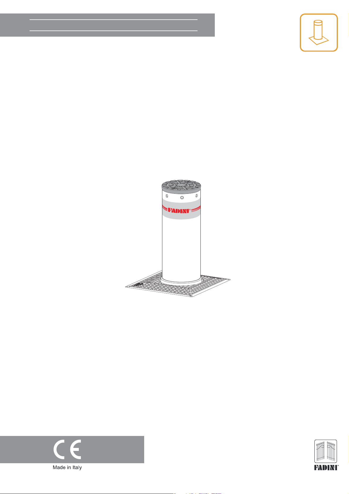
FULLY RETRACTABLE OIL-HYDRAULIC BOLLARDS.
POST DIAMETER 100 mm
EN 13241
EN 12453
EN 12445
the gate opener
Page 2

VIGILO
VIGILO
GENERAL WARNINGS FOR PEOPLE SAFETY
INTRODUCTION
This operator is designed for a specic scope of applications as
indicated in this manual, including safety, control and signaling
accessories as minimum required with FADINI equipment. □
Any applications not explicitly included in this manual may
cause operation problems or damages to properties and
people. □ Meccanica Fadini snc is not liable for damages
caused by the incorrect use of the equipment, or for
English
applications not included in this manual or for malfunctioning
resulting from the use of materials or accessories not
recommended by the manufacturer. □ The manufacturer
reserves the right to make changes to its products without
prior notice. □ All that is not explicitly indicated in this manual
is to be considered not allowed.
fully retractable oil-hydraulic bollard
□ The installer must inform and instruct the end user about the
proper use of the system by releasing him a technical dossier,
including: layout and components of the installation, risk
analysis, verication of safety accessories, verication of
impact forces and reporting of residual risks.
INFORMATION FOR END-USERS
The end-user is required to read carefully and to receive
information concerning only the operation of the installation
so that he becomes himself responsible for the correct use of it.
□ The end-user shall establish a written maintenance contract
with the installer/maintenance technician (on -call). □ Any
maintenance operation must be done by qualied technicians.
□ Keep these instructions carefully.
BEFORE INSTALLATION
Before commencing operator installation assess the suitability
of the access, its general condition and the structure. □
To check that the ground is stable, to avoid subsequent settling
or deformation in the trac control post installation area. □
Make sure that there is no risk of impact, crushing, shearing,
conveying, cutting, entangling and lifting situations, which
may prejudice people safety. □ Do not install near any source of
heat and avoid contacts with ammable substances. □ Keep all
the accessories able to turn on the operator (transmitters,
proximity readers, key-switches, etc) out of the reach of the
children. □ Transit through the access only with stationary
operator. □ Do not allow children and/or people to stand in the
proximity of a working operator. □ To ensure safety in the
whole movement area of a bollard it is advisable to install
photocells, sensitive edges, magnetic loops and detectors. □
Use yellow-black strips or proper signals to identify dangerous
spots. □ Before cleaning and maintenance operations,
disconnect the appliance from the mains by switching o the
master switch. □ If removing the actuator, do not cut the
electric wires, but disconnect them from the terminal box by
loosening the screws inside the junction box.
INSTALLATION
All installation operations must be performed by a qualied
technician, in observance of the Machinery Directive
2006/42/CE and safety regulations EN 12453 - EN 12445. □
Verify the presence of a thermal-magnetic circuit breaker
0,03 A - 230 V - 50 Hz upstream the installation. □ Use
appropriate objects to test the correct functionality of the
safety accessories, such as photocells, sensitive edges, etc. □
Carry out a risk analysis by means of appropriate instruments
measuring the crushing and impact force of the main opening
and closing edge in compliance with EN 12445. □ Identify the
appropriate solution necessary to eliminate and reduce such
risks. □ In case where the gate to automate is equipped with a
pedestrian entrance, it is appropriate to prepare the system in
such a way to prohibit the operation of the engine when the
pedestrian entrance is used. □ Apply safety nameplates with CE
marking on the gate warning about the presence of an
automated installation.
WARNINGS FOR THE CORRECT OPERATION OF THE
INSTALLATION
For optimum performance of system over time according to
safety regulations, it is necessary to perform proper
maintenance and monitoring of the entire installation: the
automation, the electronic equipment and the cables
connected to these. □ The entire installation must be carried
out by qualied technical personnel, lling in the Maintenance
Manual indicated in the Safety Regulation Book (to be
requested or downloaded from the site
www.fadini.net/supporto/downloads).
□ Operator: maintenance inspection at least every 6 months,
while for the electronic equipment and safety systems an
inspection at least once every month is required. □ The
manufacturer, Meccanica Fadini snc, is not responsible for
non-observance of good installation practice and incorrect
maintenance of the installation.
DISPOSAL OF MATERIALS
Dispose properly of the packaging materials such as
cardboard, nylon, polystyrene etc. through specializing
companies (after verication of the regulations in force at the
place of installation in the eld of waste disposal). Disposal of
electrical and electronic materials: to remove and dispose
through specializing companies, as per Directive 2012/19/UE.
Disposal of substances hazardous for the environment is
prohibited.
CE DECLARATION OF CONFORMITY of the manufacturer:
Meccanica Fadini snc (Via Mantova, 177/A - 37053 Cerea - VR - Italy) declares under own responsibility that: Vigilo complies
with the 2006/42/CE Machinery Directive, and also that it is sold to be installed in an “automatic system”, along with original
accessories and components as indicated by the manufacturing company. An automatic gate operator is, by law, a
“machinery” and therefore the installer must t the equipment with all of the applicable safety norms. The installer is also
required to issue the installer’s Declaration of Conformity. The manufacturer is not liable for possible incorrect use of the
product. The product complies with the following specic norms: analysis of the risks and subsequent action to cure them
as per EN 12445 and EN 12453, Low Voltage Directive 2014/35/UE, Electromagnetic Compatibility 2014/30/UE. In order to
certify the product, the manufacturer declares under own responsibility the compliance with the EN 13241-1 PRODUCT
NORMS.
Meccanica Fadini s.n.c.
Director in charge
2
Page 3
VIGILO
VIGILO
INSTRUCTIONS TO BE FOLLOWED BEFORE INSTALLING THE OPERATOR
FOR OPTIMAL APPLICATION AND USE OF THE OPERATOR PLEASE READ THE INSTRUCTIONS AND CONSULT EXPLANATORY DIAGRAMS.
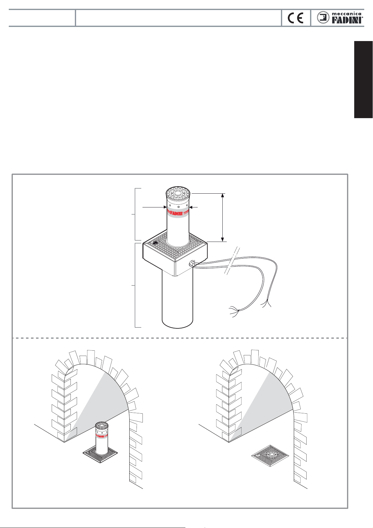
OVERVIEW
This product belongs to our range of retractable trac control posts. It is quick and easy to install, as it does not need to be
adjusted or calibrated and has been designed to regulate and prohibit vehicular access.
The oil-hydraulic bollards VIGILO 2250 (500 mm height, with or without LEDs), VIGILO 2263 (600 mm height, with or without
LEDs), VIGILO 2280 (800 mm height, with or without LEDs) are tted with posts made of rust-treated steel, 200 mm diameter;
bollards are also available in stainless steel AISI 304 version.
The product’s hallmark is its ease of installation: once the housing has been secured, the operator can be introduced ready for
operation, as soon as the wiring has been completed.
As soon as the retractable post receives a command (from a key switch or radio transmitter), it rises from its interred position.
The post is clearly visible at nighttime thanks to a reective strip and the possibility of connecting a ashing light or trac light.
Versions with led lights are also available to signal when the post is in the fully up position and when moving up or down.
Using the electronic microprocessor programmer, the operator can also be customised with presence indicator accessories
(magnetic coils, photocells).
fully retractable oil-hydraulic bollard
English
Retractable post
Container unit inside the housing
to be sunk in a dedicated trench
in the ground
Ø 200
stroke 500 mm (Vigilo 2250)
stroke 600 mm (Vigilo 2263)
stroke 800 mm (Vigilo 2280)
Length of cables 10 metres
Raised post, access prohibited Lowered post, access free
3
Pic. 1
Page 4
VIGILO
VIGILO
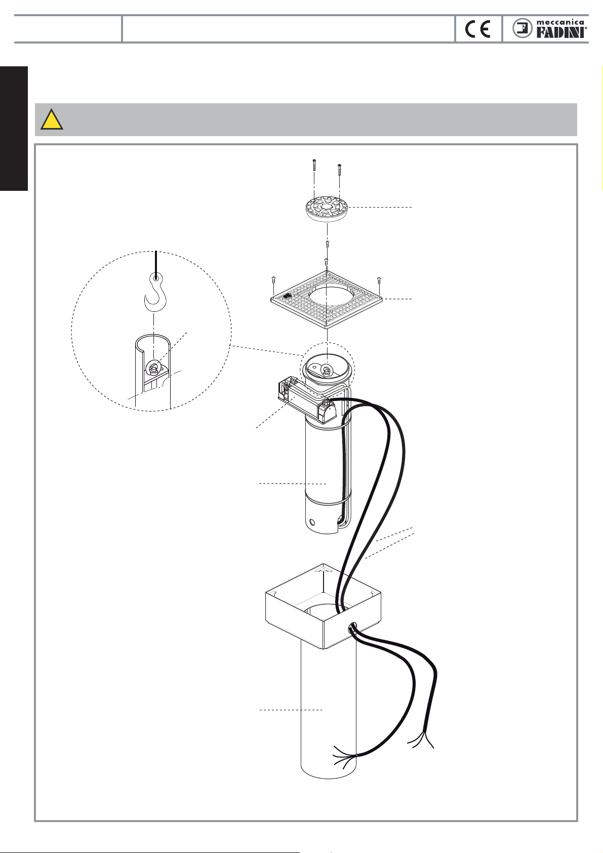
PRELIMINARY OPENING OF ALL FUNCTIONAL COMPONENTS
Start by removing the cover plate to reveal the operator and separate the individual components, with the aid of a hoist (Pic. 2):
this makes it easy to extract the internal piston and hydraulic main unit container unit.
IMPORTANT: TAKE CARE NOT TO TEAR OR CUT WIRES.
!
fully retractable oil-hydraulic bollard
English
Post cover with
rubber buer
Cover plate
Detail of retractable post
with hoisting connection
Cylindrical container
for oil-hydraulic piston
Eyebolt
Hydraulic main unit
Motor and limit switch cables.
LED and solenoid valve versions
also come with pre-tted
cables in lengths of 10 m each
Housing
Pic. 2
4
Page 5
VIGILO
VIGILO
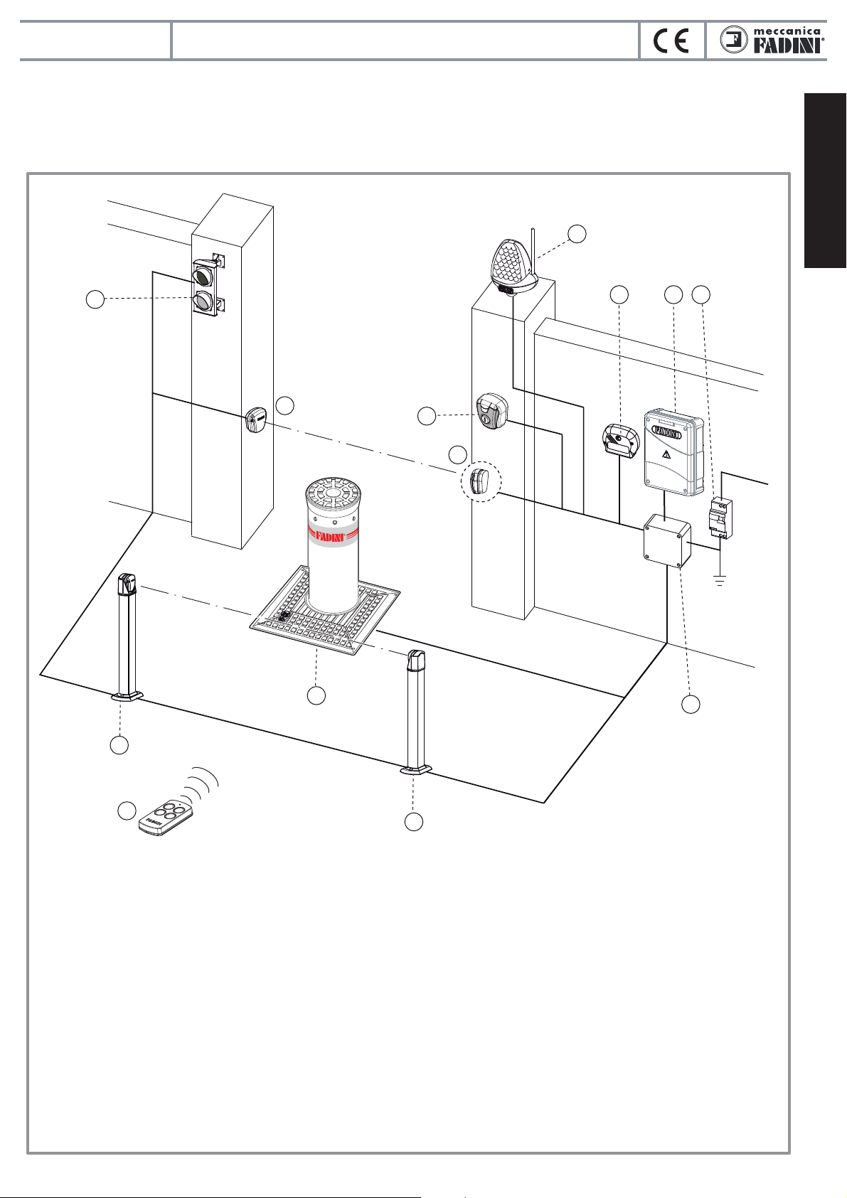
ELECTRICAL LAYOUT OF THE INSTALLATION
To check that the mains supply and voltage to the electric motor is 230 V at 50 Hz.
The power supply to the operator’s built-in motor must be made using electricity cables with a 1,5 mm² section for a maximum
distance of 50 metres. For distances of over 50 metres, use electric cables with sections suited to the installation.
fully retractable oil-hydraulic bollard
1
English
10
2x1 mm²
4x1 mm²
234
2x1 mm²
cable RG58
6
7
11
4x1 mm²
3x1 mm²
8
2x1 mm²
F
ADINI
230 V - 50 Hz
4x1 mm²
4x1 mm²
5
8
4x1 mm²
9
1 - MIRI 4-Led ashing light with built-in aerial
2 - Stand alone VIX 53/1 R radio receiver
3 - ELPRO S40 electronic programmer
4 - Dierential circuit breaker switch (sensitivity 30 mA, protection 6-10 A)
5 - Junction box, electric wires
6 - FIT 55 photocell receiver
7 - VIGILO post
8 - FIT 55 photocell projector
9 - VIX 53/4 TR transmitter
10 - Trac light with two lights
11 - CHIS 37 key-switch
6
Pic. 3
5
Page 6

VIGILO
VIGILO
ARRANGING THE HOUSING
fully retractable oil-hydraulic bollard
English
850 - stroke 500 mm
170
960 - stroke 600 mm
1.140 - stroke 800 mm
410
FRONT SIDE
Ø 275
410 mm
Ø 60
Possible
submersed
pump
Check soil natural permeability: 50 liters of water must be
able to soak away in not longer than 30/40 minutes.
!
Otherwise provide a pipe to allow rain water to ow either
into the sewage system or a sump well equipped with a
submersed pump.
Soakaway pebbles
IMPORTANT: once the housing has been positioned and installation completed, it is important for the top edge
!
to be level with the ground.
Concrete
Cover with
about 30 cm
30 cm
of concrete
1,0 m - stroke 500
1,2 m - stroke 600
1,3 m - stroke 800
23 cm
87 cm
87 cm
43,5 cm
FRONT SIDE
43,5 cm
23 cm
Piping Ø 5 cm
for passage
of electric wires
12 cm
depth piping
centre
Housing
Spirit level
Pic. 4
cast
15 cm
loose pebble
drainage layer
6
15 cm
Pic. 5
Page 7

VIGILO
VIGILO
PLACING THE TRAFFIC CONTROL POST INSIDE THE HOUSING
Before performing this operation, wait for the housing to be secured rmly in place. Do not commence until the concrete has set
and the electric wire pipe has been secured and covered with soil.
• Use a hoisting hook to lift the piston unit with the post and main unit (using the eyebolt) and place on top of the housing.
• The subsequent phase of this operation consists in threading the motor, limit switch, solenoid valve and LED power supply
electric wires through the piping and simultaneously starting to delicately place the operator inside the housing.
IMPORTANT: PASS THE MOTOR, LIMIT SWITCH, SOLENOID VALVE AND LED POWER SUPPLY ELECTRIC WIRES
!
THROUGH THE PIPING WITHOUT TEARING OR CUTTING THE CABLES.
Hoisting
hook
fully retractable oil-hydraulic bollard
English
Oil-hydraulic
piston
container unit
Housing
FRONT SIDE
Electric motor, limit switch,
solenoid valve and LED
power supply cables,
10 metres
Buried piping
Ø 50 mm
For distances greater than 10 metres, make extensions using sealed
!
junction boxes inside an accessible dividing box.
ELPRO S40
Junction
boxes
IF THE OPERATOR IS REMOVED
!
• Disconnect the main switch before opening the lid of the electric cable junction box.
• Do not cut the electric wires, rather remove them from the terminal board loosening the clamping screws inside the
dividing box.
Seal the junction boxes
using bands
7
Pic. 6
Page 8

VIGILO
VIGILO
MAGNETIC LOOP PREPARATIONS
IMPORTANT:
!
make sure that no other electro-magnetic sources are located on or under the ground near the installation to
prevent interference or any aecting action with the magnetic loops of the vehicle detecting device if installed or
with any other electronic equipment included in the system for commanding and controlling operations.
The magnetic loop detector is a safety device operating all the time to detect any transiting vehicle: the bollard is prevented from
English
rising should a vehicle cross the loop.
A hole is to be dug in the ground as indicated (see relative instructions sheet). For proper and correct functioning of the loop
detector it is recommended to strictly keep to the installation geometry as indicated in the instructions.
fully retractable oil-hydraulic bollard
Loop in
exit gateway
Loop in
exit gateway
Loop in
entry gateway
• Pre-assembled loop 6 meters across
(optional in the catalogue)
• Pre-assembled loop 12 meters across
(optional in the catalogue)
min 80 cm
ARRANGEMENT OF THE PHOTOCELLS
Visual 344
Ø 275
VIGILO bollard
Loop in
entry gateway
Power supply cable
10 meters max,
pre-tted to the loops
Fit 55
Pic. 7
Metal detector.
See instructions included
with the equipment
(optional in the catalogue)
Pic. 8
Chis 37
Elpro S40
Fit 55
1.890 mm
Electric cables laid in the ground in a corrugated sheath
min 1,0 m
min 1,0 m
Fit 55
8
Fit 55
Pic. 9
Page 9

VIGILO
VIGILO
fully retractable oil-hydraulic bollard
ELECTRICAL CONNECTIONS TO THE CONTROL BOARD
Vigilo with LED lights
ELPRO S40
closing limit switch M1
(post up)
opening limit switch M1
(post down)
VIGILO bollard
Standard Vigilo
20 μF
A
common
B
Solenoid valve
power supply
LED power supply
blinking light
11 12 13 16 17 18 22 23 52 53 52 53
brown
motor live
motor live
STABILIZER
Vigilo with
solenoid valve
Led
LED
CICALINO
Vigilo with
LED lights
blue common
Beeper
black
LED
CICALINO
Vigilo with
LED lights
FINECORSA
BLU COMUNE
Limit switch
Blue common
Standard Vigilo
blue common
blue common
LED power supply
brown
blue common
Led
Beeper
English
steady light
black
Pic. 10
FIRST OPERATION MANOEUVRES
NOTE WELL: supply the system with electric power only after all of the electrical connections have been made as
!
required for proper operations.
Having terminated installation of the trac control post and all the safety and control accessories (all of the NC contacts on the
Elpro S40 board are to be bridged), and the respective connections with the Elpro S40 programmer, and having completed
thorough risk analysis, the rst operation manoeuvres can be performed. If you have a radio transmitter, encode the radio receiver
according to the relative instructions before giving the command to raise the retractable post, or give the manoeuvre command
using a key switch. Once power is supplied, connect the motor/pump cable and, satised that the limit switch LEDs are properly
alight, the post should move up on the rst commanding pulse; should it fail, disconnect power supply and swap the connections
to the live terminals.
NC
230 V
All NC contacts are to be closed
Should the motor fail
to drive the post up by
A
rst pulsing, swap the
B
connections to the electric
20 μF
motor live terminals only
16 1817 16 1817
common
common
st
pulse
1
In case of multiple installations go
through the same procedure with each post
9
Pic. 11
Page 10

VIGILO
VIGILO
fully retractable oil-hydraulic bollard
VERSION OF CORAL WITH SOLENOID VALVE
In the version of VIGILO with solenoid valve no manual overriding action is needed, and in case of power failure the post descends
automatically ush with pavement level. To enable the solenoid valve to operate properly, the electric wires labelled
“ELETTROVALVOLA - Solenoid valve” from the post assembly are to be connected, through the voltage stabilizer, to terminals 22
and 23 in the Elpro S40 control box.
VIGILO with solenoid valve
English
22 23
STABILIZER
SOLENOID VALVE
230 V
GROUND-LEVEL CLOSURE - COVER PLATE
• Use the four screws to close the cover plate.
• Lift the retractable post for facilitate closure of the post cover
with the buer, give the command (by encoding a transmitter
with the radio receiver or a key switch) to lift the retractable
post.
==
VIGILO with solenoid valve VIGILO with solenoid valve
230 V
Pic. 12
Post cover
Rubber buer
Cover plate
Retractable
post
NO
IMPORTANT:
WE RECOMMEND
GREASE
GREASING ALL CLAMPING
SCREWS
MANUAL RELEASE OPERATIONS
In the case of a blackout, the post can be lowered manually following the instructions show in pic. 14.
1
4
2 3
Insert the release key
in the release key recess
Release the hydraulic circuit
by turning the release key
one turn anti-clockwise
5
12
1
11
2
10
9
3
8
4
Block the hydraulic circuit
567
by turning the release key
clockwise (tighten until
securely locked)
Pic. 13
12
11
10
9
8
1
2
3
4
567
Press to lower the post manually
Pic. 14
10
Page 11

VIGILO
VIGILO
fully retractable oil-hydraulic bollard
MAINTENANCE RECORD
hand over to the end user of the installation
the gate opener
Installation address:
Installation type:
Sliding gate
Swinging gate
Over-head door
Lateral folding
door
NOTE WELL: this document must record any ordinary and extraordinary services including installation, maintenance,
repairs and replacements to be made only by using Fadini original spare parts.
This document, for the data included in it, must be made available to authorized inspectors/ocers, and a copy of it must
be handed over the end user/s.
The installer/maintainer are liable for the functionalities and safety features of the installation only if maintenance is
carried on by qualied technical people appointed by themselves and agreed upon with the end user/s.
Service date
N°
Folding door
Road barrier
Bollard
.............................
Maintainer: Date:
Operator model:
Dimensions per gate leaf:
X
Weight per gate leaf: Installation date:
Technical maintainer End user/sService description
Quantity of models
installed:
English
1
2
3
4
give to the end-user of the installation
5
6
Stamp and signature
installation technician/maintainer
Signed for acceptance
end user
buyer
11
Page 12

VIGILO
VIGILO
English
fully retractable oil-hydraulic bollard
12
Page 13

VIGILO
VIGILO
OPERATIONS FOR ORDINARY ROUTINE MAINTENANCE OF FADINI AUTOMATIC BOLLARDS (EVERY SIX MONTHS)
The standard maintenance routine sequence is as follows:
• Clean the ground cylinder and suck all material settlements.
• Clean water drains located at the bottom of the ground cylinder and/or excavation pit.
• Check any possible oil leaking from the hydraulic piston and, in case, x it.
• Overhaul the screws fastening the bollard to the ground cylinder, making sure they are properly tightened and lubricated.
• Check the oil-hydraulic motor-pump and oil pressure by assessing the rising times of the bollard. If required, top up oil in the
reservoir and/or parallel add an extra capacitor to the existing one (instructions manual is to be referred to).
• Check the correct functioning of the signal LED lights (if incorporated) in the bollard head.
• Sight check the electronic board controlling the bollard/s (e.g.: “ooded” relay contacts, oxidized terminal clamps, etc.).
• Check the correct functioning and positioning of the limit switches.
• Check the release system for bollard manual operations.
• Clean and recondition the rising cylinder if required, e.g.: paint patching up, replacing the back reecting sticker and /or the
cover tted with rubber edge.
IF OPTIONAL ACCESSORIES ARE INCLUDED, FURTHER MAINTENANCE IS REQUIRED AS FOLLOWS:
• Check the correct functioning of the safety accessories such as the inductive loop/s and the photocells.
• Check the correct functioning of the radio receiver and all of the remote controls.
• Check the correct functioning of the pressure switch.
• Check the correct functioning of the beeper.
• Check the correct functioning of the trac lights and the respective control card.
• Check the correct functioning of the solenoid valve in emergency cases such as power failure or disconnection, assess
therefore the status of the 24 Vdc voltage stabilizer.
• Check the correct functioning of EAR 35 acoustic analyzer to lower the bollard in emergency.
fully retractable oil-hydraulic bollard
English
13
Page 14

VIGILO
VIGILO
fully retractable oil-hydraulic bollard
!
1) Installation operations, testing, analysis of the risks and future maintenance are to be executed by qualied and authorized
technicians in compliance with the existing regulations (www.fadini.net/supporto/download).
2) This automatic system is intended to be exclusively used for the applications described in this manual, including all of the
English
safety and command accessories, at least as required.
3) Any application not indicated in this manual may cause malfunctioning or damages to people and properties.
4) Make sure the soil is adequate to take the bollard to avoid that settling at a later stage causes problems to the system.
5) Make sure the site is free from utilities that may interfere with it.
6) Make sure that electromagnetic sources are at a suitable distance from the accessories, especially from the loop detectors.
The magnetic elds of other sources might aect the detections of the safety loops as well as those of the other command
and safety devices of the system.
7) Make sure the power supply to the electric motor is 230 V (50 Hz).
8) It is recommended either of the following power supply cables:
- 10 meters electric cable 4x1 mm² for motor pump power supply;
- 10 meters electric cable 3x0,5 mm² for limit switches.
The section of the ground cable is to be chosen in compliance with the requirements of the installation site.
9) In case any components or accessories need replacing, use only original parts as provided by the manufacturer.
10) The installer shall provide the nal user with information related to all of the operating commands and functions of the
system, including that concerning lowering of the post in case of an emergency (manual release operation).
11) The installer shall inform the nal user of the dangers coming from the presence of persons, especially children, in the
proximity of the bollard.
12) The manufacturer reserves the right to change this manual without previous notice.
As far as conguration and execution of the system are concerned, these are to comply with the laws in the country of
installation.
INFORMATION ABOUT SAFETY AND PROPER FUNCTIONING OF THE SYSTEM
!
Meccanica Fadini is not liable for any possible damages derived from incorrect use or from any use not
indicated in this manual, furthermore it is not answerable for malfunctioning caused by the use of materials
!
or accessories not approved by the company itself.
It is to be noted that the product respects the impact and breakout resistance values as indicated provided
that the installation of the same is carried out in observance of the specications included in this manual of
instructions. Various factors are to be carefully taken into consideration such as compaction index, soil
permeability coecient, concrete type, which may aect the indicated values even signicantly.
PRODUCT SPECIFICATIONS
Heavy duty, fully retractable, automatic bollard made up of an incorporated oil-hydraulic motor pump unit and an
oil-hydraulic actuator inside the moving cylinder. Suitable for applications in private and commercial areas, and for industrial
installations. IP67. The height of the rising cylinder (from ground level) can be 500/600/800 mm. The rising cylinder is made
of S235JRH steel, thickness 4 mm and Ø 200 mm, cataphoresis treated and powder coated. Rising cylinder also available in
AISI 304 brushed stainless steel. Rubber ring on rising cylinder head. Cataphoresis treated aluminium cover with slip proof
nish on treadable top. Rising cylinder tted with high intensity, microprismatic, retroreecting approved sticker (h 80 mm),
available with signal LEDs (N.8) with ashing light tted all around the top. Hot dip galvanized steel casing for ground
foundation, tted with a cover allowing access to the hydraulic release for manual lowering of the bollard by a special
spanner in an emergency. Impact resistance 30.000 J, breakout resistance 160.000 J, static load max 1.600 kg in standing
position, max 20.000 kg in lowered position. Working temperature -40°C +80°C. Supply voltage 230 Vac ± 10%, 50 Hz.
Absorbed power 330 W. Rising time ~ 5,1 s [rising cylinder H 500 mm], ~ 5,9 s [rising cylinder H 600 mm] ~ 7,7 s [rising cylinder
H 800 mm]. Frequency of use 2.000 cycles/day. Hydraulic device to lock the bollard in the standing position, on request a
solenoid valve can be tted for the spontaneous descent of the bollard in case of a power failure.
14
Page 15

VIGILO
VIGILO
TECHNICAL DATA
ELECTRIC MOTOR
Power output 0,25 kW (0,33 HP)
Supply voltage 230 Vac
Frequency 50 Hz
Absorbed power 330 W
Absorbed current 1,8 A
Motor revolutions 2.800 rpm
Capacitor 20 μF
Service mode S3
HYDRAULIC ACTUATOR
Shaft diameter 16 mm
Piston diameter 30 mm
Pre-set pushing power 15 daN
Protection standard complete IP 55
fully retractable oil-hydraulic bollard
OIL-HYDRAULIC MOTOR-PUMP UNIT VICO 2240
Hydraulic pump P10
Pump ow rate 4,45 l/min
Working pressure 20 atm
Max pressure 40 atm
Working temperature -20 °C +80 °C
Oil type Oil Fadini - Item 708L
Static weight of pump assembly 10 kg
Pump protection standards IP 67
[A] -40 °C with specic optional accessories (Ref. General Catalogue).
[A]
English
FEATURES
Impact resistance
Crash resistance
Max static load
Bollard weight
Post diameter
Post height
Post nishing
Post material
Post material Stainless Steel/inox version
Bollard thickness
Ground sleeve treatment
[B] With Vigilo models tted with a solenoid valve,the weights are 20 kg higher than those indicated in the table.
PERFORMANCE - VIGILO 2250
Frequency of use intensive
Service cycle rise ~5,1 s
dwell 30 s
lower ~4,3 s
dwell 30 s
Complete cycle time ~69 s
Complete cycles
rise-dwell-lower-dwell No. 52/hour
Annual cycles
(with 8 hours of use per day) No. 151.840
[B]
VIGILO 2250
30.000 J
160.000 J
20.000 kg
102 kg
ø 200 mm
powder coating polyester
anthracite grey RAL 7016
PERFORMANCE - VIGILO 2263
Frequency of use intensive
Service cycle rise ~5,9 s
dwell 30 s
lower ~5,2 s
dwell 30 s
Complete cycle time ~71 s
Complete cycles
rise-dwell-lower-dwell No. 51/hour
Annual cycles
(with 8 hours of use per day) No. 148.920
500 mm
powder coating polyester
anthracite grey RAL 7016
S235J steel
AISI 304
4 mm
hot dip galvanization
VIGILO 2263
30.000 J
160.000 J
20.000 kg
110 kg
ø 200 mm
600 mm
S235J steel
AISI 304
4 mm
hot dip galvanization
PERFORMANCE - VIGILO 2280
Frequency of use intensive
Service cycle rise ~7,7 s
dwell 30 s
lower ~7,0 s
dwell 30 s
Complete cycle time ~74 s
Complete cycles
rise-dwell-lower-dwell No. 48/hour
Annual cycles
(with 8 hours of use per day) No. 140.160
VIGILO 2280
30.000 J
160.000 J
20.000 kg
131 kg
ø 200 mm
800 mm
powder coating polyester
anthracite grey RAL 7016
S235J steel
AISI 304
4 mm
hot dip galvanization
15
Page 16

VIGILO
VIGILO
OVERALL DIMENSIONS AND DIAGRAM
fully retractable oil-hydraulic bollard
100
65
55
English
45
28
24
19
Vehicle SPEED (km/h)
Vehicle
MASS (kg)
Various factors, such as the compaction index, soil permeability
coecient and kind of concrete may reduce the values indicated in
the diagram even signicantly.
Overall dimensions
Vigilo 2250
Vigilo 2263
Vigilo 2280
1.000
1.400
2.100
A
500
600
410Cø 200D410E170Fø 275
800
30.000 J
160.000 J
3.000
B
850
960
1.140
N.W. - Measurements are in millimeters (mm).
- Each Vigilo bollard is supplied equipped with electric cables of 10 meters in length
(for electric motor, limit switch, solenoid valve, leds).
C=200
AA
BD
E
F
Cable
length
10 meters
G
H
1.350
410
1.560
1.940
410
H
G
Pic. 15
Via Mantova, 177/A - 37053 Cerea (VR) Italy
Ph. +39 0442 330422 Fax +39 0442 331054
info@fadini.net - www.fadini.net
2012/19/UE Directive
GB
Re. disposal of electric
and electronic waste
DISPOSE PROPERLY OF MATERIALS
ARMFUL TO THE ENVIRONMENT
2018/11
 Loading...