

Page 1
READ THESE INSTRUCTIONS BEFORE YOU START INSTALLING THIS RANGEHOOD
WARNING: - TO REDUCE THE RISK OF A RANGE TOP GREASE FIRE: Keep fan, filters and grease laden surfaces clean.
Always turn hood ON when cooking at high heat. Use high range setting on range only when necessary. Heat oil slowly
on low to medium setting. Don’t leave range unattended when cooking. Always use cookware and utensils appropriate
for the type and amount of food being prepared.
WARNING: - TO REDUCE THE RISK OF INJURY TO PERSONS IN THE EVENT OF A RANGE TOP GREASE FIRE, OBSERVE
THE FOLLOWING: SMOTHER FLAMES with a close-fitting lid, cookie sheet, or metal tray, then turn off the burner. BE
CAREFUL TO PREVENT BURNS. If the flames do not go out immediately EVACUATE AND CALL THE FIRE DEPARTMENT.
NEVER PICK UP A FLAMING PAN - You may be burned. DO NOT USE WATER, including wet dishcloths or towels - a
violent steam explosion will result. Use an extinguisher ONLY if: 1. You know you have a Class ABC extinguisher, and
you already know how to operate it. 2. The fire is small and contained in the area where it started. 3. The fire department
is being called. 4. You can fight the fire with your back to an exit.
ALL WALL AND FLOOR OPENINGS WHERE THE RANGEHOOD IS INSTALLED MUST BE SEALED.
This rangehood requires at least 24" of clearance between the bottom of the rangehood and the cooking surface or countertop.
The maximum depth of overhead cabinets is 13". Overhead cabinets on both sides of this unit must be a minimum of 18" above the
cooking surface or countertop. Consult the cooktop or range installation instructions given by the manufacturer before making any
cutouts. MOBILE HOME INSTALLATION The installation of this rangehood must conform to the Manufactured Home Construction
and Safety Standards, Title 24 CFR, Part 3280 (formerly Federal Standard for Mobile Home Construction and Safety, Title 24, HUD,
Part 280). Four wire power supply must be used and the appliance wiring must be revised. See Electrical Requirements.
CRISTAL
Slideout Rangehood
• Installation Instructions
• Use and Care Information
READ AND SAVE THESE INSTRUCTIONS
The Installer must leave these instructions with the homeowner.
The homeowner must keep these instructions for future reference
and for local electrical inspectors' use.
Version 11/98 - Page 1
LISEZ BIEN CETTE FICHE AVANT D'INSTALLER LA HOTTE
AVERTISSEMENT: - POUR RÉDUIRE LE RISQUE DE FEU: Gardez le ventilateur, les filtres ainsi que toute autre superficie
propre. Utilisez la hotte pour cuisson à haute température. N'utilisez le feu vif que si nécessaire. Chauffez l'huile
doucement. Surveillez toujours la cuisson. Utilisez toujours des casseroles de taille convenable pour la cuisson.
AVERTISSEMENT: - POUR PRÉVENIR LES BLESSURES EN CAS DE FEU SUIVRE LES RECOMMANDATIONS SUIVANTES:
ÉTOUFFEZ LE FEU avec un couvercle métallique et fermez le brûleur. Si le feu ne s'éteint pas tout de suite, QUITTEZ
LES LIEUX ET APPELEZ LES POMPIERS. NE TOUCHEZ JAMAIS UNE CASSEROLE EN FLAMMES. N'UTILISEZ JAMAIS
DE L'EAU ou un torchon mouillé pour éteindre le feu - ce qui pourrait causer une explosion de vapeur. N'utilisez un
extincteur que si: 1. Vous avez un modèle ABC et vous connaissez bien son mode d'emploi. 2. Le feu est petit et peu
répandu. 3. Les pompiers sont déjà prévenus. 4. Vous avez une sortie derrière vous.
TOUTE OUVERTURE DANS LE MUR OU LE PLANCHER À PROXIMITÉ DE LA HOTTE DOIT ÊTRE SCELLÉ
Gardez 24 po. de hauteur entre le bas de la hotte et la surface de cuisson. Les armoires au-dessus ne dépasseront pas 13 po.
de profondeur. Les armoires au-dessus de chaque côté devront être au moins à 18 po. au-dessus de la surface de cuisson.
Consultez la fiche technique avant de découper les armoires. L'installation de cette hotte doit être conforme aux Réglements
de Manufactured Home Construction and Safety Standards, titre 24 CFR, Section 3280 (anciennement Federal Standard for
Mobile Home Construction and Safety Standards, titre 24 CFR, Section 3280 (anciennement Federal Standard for Mobile Home
Construction and Safety, titre 24, HUD, Section 280). Le branchement électrique se fait avec une raccordement à 4 fils. Consultez
la fiche technique électrique.
Page 2
VENTING REQUIREMENTS
Determine which venting method is best for your application.
Ductwork can extend either through the wall or the roof.
The length of the ductwork and the number of elbows should
be kept to a minimum to provide efficient performance. The
size of the ductwork should be uniform. Do not install two
elbows together. Use duct tape to seal all joints in the ductwork
system. Use caulking to seal exterior wall or floor opening
around the cap.
Flexible ductwork is not recommended. If it is used, each foot
of flexible ductwork used is equivalent to two feet of straight
metal ductwork when calculating the ductrun length. Thus,
a flexible elbow equals two standard elbows.
Make sure there is proper clearance within the wall or floor
for exhaust duct before making cutouts. Do not cut a joist or
stud unless absolutely necessary. If a joist or stud must be
cut, then a supporting frame must be constructed. For best
results, remote blowers should transition to 9" round duct
as soon as possible. If small ducting is used, it should be
transition to 9" round as soon as possible.
WARNING - To Reduce The Risk Of Fire, Use Only Metal
Ductwork.
ELECTRICAL REQUIREMENTS
A 120 volt, 60 Hz AC-only electrical supply is required on
a separate 15 amp circuit, fused on both sides of the line.
A time-delay fuse or circuit breaker is recommended. The
fuse must be sized per local codes in accordance with the
electrical rating of this unit as specified on the serial/rating
plate located inside the unit near the field wiring compartment.
THIS UNIT MUST BE CONNECTED WITH COPPER WIRE
ONLY. Wire sizes must conform to the requirements of the
National Electrical Code, ANSI/NFPA 70 - latest edition, and
all local codes and ordinances. Wire size and connections
must conform with the rating of the appliance. Copies of the
standard listed above may be obtained from:
National Fire Protection Association
Batterymarch Park
Quincy, Massachusetts 02269
Version 11/98 - Page 2
• Venting system MUST terminate outside the
home.
• DO NOT terminate the ductwork in an attic or
other enclosed space.
• DO NOT use 4" laundry-type wall caps.
• Flexible-type ductwork is not recommended.
• DO NOT obstruct the flow of combustion and
ventilation air.
• Failure to follow venting requirements may result
in a fire.
This appliance should be connected directly to the fused
disconnect (or circuit breaker) through flexible, armored or
nonmetallic sheathed copper cable. Allow some slack in the
cable so the appliance can be moved if servicing is ever necessary. A UL Listed, 1/2" conduit connector must be provided
at each end of the power supply cable (at the appliance and
at the junction box).
When making the electrical connection, cut a 1 1/4" hole
in the wall. A hole cut through wood must be sanded until
smooth. A hole through metal must have a grommet.
WARNING - TO REDUCE THE RISK OF FIRE, ELECTRICAL SHOCK, OR INJURY TO PERSONS, OBSERVE THE
FOLLOWING: Use this unit only in the manner intended
by the manufacturer. If you have any questions, contact
the manufacturer. Before servicing or cleaning unit,
switch off power at service panel and lock service panel
to prevent power from being switched on accidentally.
When the service disconnecting means cannot be locked,
securely fasten a prominent warning device, such as a
tag, to the service panel.
Installation Work And Electrical Wiring Must Be Done By
Qualified Person(s) In Accordance With All Applicable
Codes And Standards, Including Fire-Rated Construction.
When cutting or drilling into wall or ceiling, do not damage electrical wiring and other hidden utilities. Ducted
fans must always be vented to the outdoors.
Sufficient air is needed for proper combustion and
exhausting of gases through the flue (chimney) of fuel
burning equipment to prevent backdrafting. Follow the
heating equipment manufacturer's guideline and safety
standards such as those published by the National Fire
Protection Association (NFPA), and the American Society
for Heating, Refrigeration and Air Conditioning Engineers
(ASHRAE), and the local code authorities.
CAUTION: For General Ventilating Use Only. Do Not
Use To Exhaust Hazardous or Explosive Materials and
Vapors.
For Remote Blowers only: CAUTION: This unit has an unguarded impeller. Do Not Use In Locations Readily Accessible
To People Or Animals.
WARNING
• Electrical ground is required on this rangehood.
• If cold water pipe is interrupted by plastic,
nonmetallic gaskets or other materials, DO NOT
use for grounding.
• DO NOT ground to a gas pipe.
• DO NOT have a fuse in the neutral or grounding
circuit. A fuse in the neutral or grounding circuit
could result in electrical shock.
• Check with a qualified electrician if you are in doubt
as to whether the rangehood is properly grounded.
• DO NOT use this appliance with any solid state fan
speed control device.
• Failure to follow electrical requirements may result
in a fire.
WARNING
!
!
Page 3
RÈGLEMENTS D'ÉVACUATION
Confirmer la sortie d'évacuation - soit par le mur, soit par
le toit.
Utilisez une longueur de tuyauterie minimale avec les moindres
de coudes pour la plus grande efficacité. Le diamètre de
tuyauterie doit être uniforme. N'installez jamais 2 coudes
ensemble. Scellez bien tous les joints avec un ruban adhésif
métallique à l'intérieur et scellez bien le clapet extérieur avec
du calfeutrage.
Utilisez un tuyau d'évacuation rigide lorsque possible. Un
tuyau flexible égale deux fois plus qu'un tuyau rigide, ce qui
réduit la puissance d'évacuation.
Veillez à ce que l'espace pour le tuyau soit ample - ainsi on
n'aurait pas besoin de découper les supports de mur intérieur.
Si ce découpage est nécessaire, veillez bien à ce qu'un
renforcement soit mis en place.
Pour de meilleurs résultats, utilisez un tuyau de transition de
9 pouces dès que possible.
AVERTISSEMENT - Pour Ne Pas Risquer Un Feu, Utilisez
Seulement Les Matériaux Métalliques.
Raccordez cet appareil directement au coupe-circuit avec un fil
flexiblle couvert en cuivre en laissant un peu de lâchement dans
le fil pour permettre le déplacement de l'appareil. Veillez a ce
qu'un contact d'un demi-pouce (1/2 po.) soit installé à chaque
bout de fil (soit à l'appareil ainsi qu'à la boite à fusible).
Faites un trou de 1 1/4 po. dans le mur. S'il s'agit d'un trou en
bois - sablez-le bien, tandis qu'un trou passant par le métal
demande un bouche-trou.
AVERTISSEMENT - POUR RÉDUIRE LE RISQUE DE
FEU OU UNE SECOUSSE ELECTRIQUE: Suivez les
recommandations du fabricant et entre en communication
avec lui pour toute information. Fermez le courant avant
tout entretien et veillez a ce qu'il reste fermé. Si on ne
peut pas verrouiller le panneaux du service électrique,
affichez un avis de danger sur la porte.
L'installation Et Le Raccordement Electrique Doivent Se
Faire Par Un Technicien Qualifié Selon Tous Les Codes
Municipaux. En perçant un mur veillez à ne pas perforer
un autre fil électrique. Une hotte à évacuation extérieure
doit être raccordée à l'extérieur. Si elle est à installer
au-dessus d'une baignoire ou une douche, prévoir à ce
qu'elle soit conforme à cet usage.
Afin d'obtenir un rendement maximal en ce qui a trait à la
combustion ainsi qu'à l'évacuation des gaz par la conduite
de cheminée, une bonne aération est nécessaire pour
tous les appareils à combustion. Suivez les conseils et
mesures de sécurité du fournisseur tels que ceux publiés
par l'Association Nationale de la Sauvegarde contre
l'Incendie et l'Association Américaine d'Ingénieurs de
Chauffage, Frigorifaction et Air Climatisé ainsi que les
codes municipaux.
AVIS: Pour L'évacuation Générale - Veillez à Ne Pas
Evacuer Des Matériaux Ou Vapeurs Explosif.
AVIS: Pour La Hotte Avec Une Turbine Extérieure - Veillez
Bien À Ce Que Les Lieux D'installation Soient Hors D'Atteinte
Des Enfants Et Des Animaux.
Version 11/98 - Page 3
AVERTISSEMENT
• Le système d'évacuation DOIT sortir à l'extérieur.
• N'ÉVACUEZ PAS le conduit soit dans une
mansarde soit dans un espace enfermé.
• N'UTILISEZ PAS un clapet de séchoir à 4 pouces.
• N'utilisez pas un conduit flexible.
• N'ENCOMBREZ PAS la circulation d'air.
• Faute de suivre cet avertissement pourrait
occasionner un feu.
FICHE TECHNIQUE ÉLECTRIQUE
Le raccordement électrique doit se faire avec un circuit
séparé de 15 ampères (fusible de chaque côté) à 120V, 60
Hz, courant alternant. On recommande un coupe-circuit.
La taille du fusible doit se conformer aux codes municipaux
suivant la spécification électrique sur la plaque intérieure.
Le diamètre du fil devra aussi se conformer aux règlements
du code national électrique, ANSI/NFPA 70 - ainsi qu'aux
règlements locaux et les spécifications de cet appareil. On
peut obtenir ces informations chez:
l'Association Nationale de la Prévention du Feu
Batterymarch Park
Quincy, Massachusetts 02269
• Une prise à terre est nécessaire pout cette hotte.
• N'utilisez pas un tuyau à l'eau froide pour la mise
à terre s'il est branché à un joint plastique, nonmétallique ou autre.
• NE JOIGNEZ PAS la mise à terre à conduit de gaz.
• N'INSTALLEZ PAS un fusible dans le circuit de
mise à terre - ce qui peut causer une secousse
électrique.
• Vérifiez avec un électricien certifié à ce que la hotte
soit bien mise à terre.
• Faute de suivre ces recommandations pourrait
occasionner un feu.
AVERTISSEMENT
!
!
Page 4
TOOLS NEEDED FOR INSTALLATION
• Saber Saw or Jig Saw
• Drill
• 1 1/4" Wood Drill Bit
• Pliers
• Phillips Screwdriver
• Flat Blade Screwdriver
• Wire Stripper or Utility Knife
• Metal Snips
• Measuring Tape or Ruler
• Level
• Pencil
• Caulking Gun
• Duct Tape
PARTS SUPPLIED FOR INSTALLATION
• 1 Backdraft Damper
• 2 Screws
• 1 Literature Package
PARTS NEEDED FOR INSTALLATION
• 2 Conduit Connectors
• Power Supply Cable
• 2 Wood Blocks - 1" x 1" x 5"
• 4 Wood Screws - 1 1/4"
• 1 Wall or Roof Cap
• All Metal Ductwork
PLAN THE DUCTWORK
The Cristal slideout rangehood is designed to offer wide
flexibility of installations. The rangehood can be ducted
vertically or horizontally through a 3 1/4" X 10" rectangular vent.
The unit can also be installed in a recirculating configuration.
FIGURES 1 and 2 show horizontal and vertical ducting
installations for this unit. FIGURE 3 shows recirculating
installation.
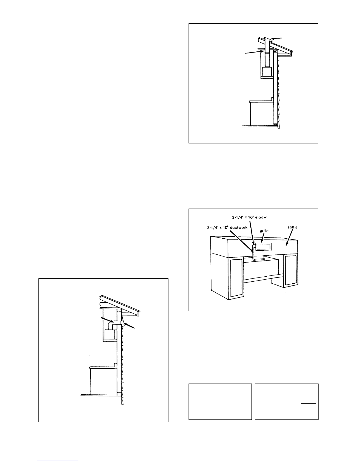
HORIZONTAL DUCTING
Version 11/98 - Page 4
VERTICAL DUCTING
FIGURE 2
RECIRCULATING INSTALLATIONS
For recirculating installations, filter kit 6093033 is necessary.
The charcoal filters must be inserted behind the grease filters.
The back of the charcoal filters are supported by a small pin
on the outside edge and a metal flange on the inside edge.
The front of the charcoal filters have plastic tabs that lock
into place when the filter is pushed upward. The plastic grille
supplied with the kit can be used to cover the duct opening as
illustrated in FIGURE 3.
FIGURE 3
CALCULATE THE DUCTRUN LENGTH
The ductwork length should not exceed 26 feet. For best
results, use no more than three 90° elbows. Make sure that
there is a minimum of 24" of straight duct between elbows if
more than one is used. Do not install two elbows together.
Calculate the length of the ductwork by adding the equivalent
feet listed in FIGURE 4 for each piece of duct in the complete
system. An example is given in FIGURE 5.
FIGURE 4
7.0 feet
5.0 feet
12.0 feet
0.0 feet
45˚ Elbow
90˚ Elbow
90˚ Flat Elbow
Wall Cap
FIGURE 5
9 Feet Straight Duct
2 - 90˚ Elbows
Wall Cap
Total System
9.0 feet
10.0 feet
0.0 feet
19.0 feet
FIGURE 1
3 - 1/4" X 10"
ductwork
through the roof
roof cap
3 - 1/4" X 10"
ductwork
through the wall
wall cap
Page 5

FIGURE 6
PLAN THE DUCTWORK
First, determine which venting option will be used:
• Horizontal
• Vertical
• Recirculating
FIGURE 7 shows the cabinet cutout dimensions for both 30"
and 36" models. The duct exit will depend upon your specific
installation. For recirculating installations, the duct work must
be extended through the soffit and be covered with a grille.
The charcoal filters and grille are sold as a kit.
PREPARE THE CABINET
1. Disconnect and move freestanding range from cabinet
opening to provide easier access to upper cabinet and rear
wall. Put a thick, protective covering over cooktops, set-in
ranges or countertops to protect from damage or dirt.
2. Determine and clearly mark with a pencil the center line
of the cabinet on the wall and on the underside of the cabinet
where the rangehood will be installed.
3. If the cabinet bottom is recessed, wood filler strips need
to be installed to insure proper alignment with the cabinet bottom. Wood filler strips should be flush or recessed 1/16" to
1/8" within the cabinet bottom as indicated in FIGURE 8.
FIGURE 8
Version 11/98 - Page 5
FIGURE 7
4 3/8"
3 1/4"
2"
3 1/2"
1"
Glass Screen
Extends 7"
9 1/8"
30" Model: 26"
36" Model: 32"
10"
9 1/2"
11"
30" Model: 29 7/8"
36" Model: 35 7/8"
30" Model: 13"
36" Model: 16"
8"
1 5/8"
1 1/4"
2"
2 3/8"
Page 6

4. Determine the proper cutouts for the ductwork. Make
all necessary cuts in the walls or cabinets for the ductwork.
Install the ductwork before mounting the rangehood.
5. The Cristal attaches to the cabinet through a unique
mounting system. Toggle arms illustrated in FIGURE 9 located
on each side of the rangehood support the rangehood once
it is inserted into the cabinet. The mounting arms require the
cabinet bottom to be a minimum thickness to install properly.
Measure the distance from the bottom edge of the cabinet to
the floor of the cabinet. If this distance is less than 5/8", then
the wood spacers ( 1 " x 1" x 5" ) must be used under
the toggle arms on both sides of the rangehood. Mounting
arms adjust for cabinet bottom thickness between 5/8" to 2
1/8".
6. Determine and make the proper cutout for the Power
Supply Cable. Use a 1 1/4" Drill Bit to make this hole. Run
the Power Supply Cable through the wall or cabinet. DO NOT
turn on the power until installation is complete. Use caulking
to seal around the wire opening.
INSTALL THE RANGEHOOD
1. Remove the unit from the carton and place on a flat
surface for assembly. Make sure to cover the surface to
prevent accidental damage. Remove all parts including the
backdraft damper, 2 screws, and literature package before
discarding the carton.
2. Open the glass screen and remove both grease filters
from the unit and set aside.
3. Remove the field wiring compartment cover inside the
rangehood. Using a flat blade screwdriver, remove the appropriate wiring knockout for the power supply cable.
4. Attach the backdraft damper using the two Phillips head
screws supplied with the damper.
5. Lift the rangehood into the cabinet cutout. Mounting
arms should overlap the cabinet bottom or wood spacer
blocks. Feed the Power Supply Cable through the electrical
knockout.
6. Using a flat blade screwdriver, tighten the mounting
brackets to secure the rangehood to the cabinet bottom and
to eliminate the space between the rangehood and cabinet
bottom as indicated in FIGURE 10.
WARNING
FIGURE 9
Due to the size and weight of this rangehood, more
than one person is required to help with the installation. Failure to follow these instructions may result
in personal injury.
FIGURE 10
7. Adjust the rangehood front strip if necessary. The
mounting system is designed to facilitate proper alignment
between the cabinet and rangehood. The front strip and frame
of the rangehood will adjust up to 3/8" up or down and up
to 3/4" front to back. Do not adjust more than the specified
amount. Two adjustment screws are located on each side of
the rangehood as indicated in FIGURE 11. Using a Phillips
head screwdriver, turn screws counterclockwise to loosen.
Once the front strip is adjusted, retighten the screws.
FIGURE 11
8. Connect the Power Supply Cable to the rangehood.
Attach the White lead of the power supply to the White lead
of the rangehood with a twist-on type wire connector. Attach
the Black lead of the power supply to the Black lead of the
rangehood with a twist-on type wire connector. Connect
the Green (Green and Yellow) ground wire under the Green
grounding screw.
9. Replace the field wiring compartment cover. Replace
the grease filters.
10. Turn the power supply on . Turn on Blower and Light.
IF THE RANGEHOOD DOES NOT OPERATE:
• Check that the circuit breaker is not tripped or
the house fuse blown.
• Disconnect the power supply and check that the
wiring connections have been made properly.
Version 11/98 - Page 6
!
Page 7

CUSTOMIZING YOUR RANGEHOOD
The front strip of the rangehood can be customized with either
factory supplied strips or a front strip made from the same
materials as your cabinets. Black and Brushed Aluminum
front strips are available from your dealer. The front strip is
attached to the glass screen by three recessed screws on
the back side of the strip as indicated in FIGURE 12. For a
custom front strip, a local cabinet shop can make a strip to
match your cabinets. The front strip dimensions are given
in FIGURE 13.
FIGURE 12
FIGURE 13
WARRANTY & SERVICE
This rangehood carries a limited warranty against manufacturer's defects. To obtain warranty service, contact the dealer
from whom you purchased the rangehood, or the local Faber
distributor. If you cannot identify a local Faber distributor,
contact Faber USA at (508) 358-5353 for the name of a
distributor in your area.
WIRING DIAGRAM
• This rangehood uses Flourescent Lamp Type F33-15W-T8
and Starter Type S2.
USE AND CARE INFORMATION
Rangehood Control Panel
All controls are located on the right rear side of the
rangehood.
FIGURE 14
FIGURE 15
Version 11/98 - Page 7
Side View of Rangehood
•
•
•••
30" or 36"
1 15/32"
3/4"
Glass
Screen
Front
Strip
Three Screws
Light On/Off Switch ( L )
Control A is the On/Off switch for the fluorescent light. Moving
the switch to the 1 Position turns the light On. Moving the
switch to the 0 Position turns the light Off.
Blower On/Off Switch ( M )
Control B is the On/Off switch for the blower. Moving the
switch to the 1 Position turns the blower On. Moving the
switch to the 0 Position turns the blower Off.
Blower Speed Switch ( S )
Control C is the speed control switch for the blower. Moving the
switch to the 1 Position turns the blower on LOW. Moving the
switch to the 2 Position turns the blower on MEDIUM. Moving
the switch to the 3 Position turns the blower on HIGH.
Operation Indicator Light ( I )
Red light will be on when the rangehood is operating.
Microswitches
This rangehood is equipped with two microswitches on the
glass screen, one for the light and one for the blower. When
the glass screen is pushed closed, the first microswitch will
turn the blower off. When the screen is closed completely, the
light will be turned off. The next time the screen is opened,
the rangehood will operate at the last settings.
For Best Results
Start the rangehood before cooking and allow the unit to
operate for several minutes after cooking is complete to clear
all smoke and odors from the kitchen.
Cleaning
The metal grease filters should be cleaned frequently in hot
detergent solution or placed in the dishwasher. Clean exterior
surfaces with hot soapy water. Using abrasives and scouring
agents can scratch stainless steel finishes and should not be
used to clean finished surfaces.
Replacing the Fluorescent Light
To replace the fluorescent light, remove the four screws
indicated in FIGURE 15. Remove the light diffuser cover. Be
careful as the diffuser cover is not attached to the light box.
Page 8

CONDUIT HORIZONTAL
Version 11/98 - Page 8
CONDUIT VERTICAL
FIGURE 2
FIGURE 3
FIGURE 4
7,0 pi
5,0 pi
12,0 pi
0,0 pi
Coude 45˚
Coude 90˚
Coude plat 90˚
Capuchon de mur
FIGURE 5
9 pi de conduit droit
2 Coudes 90˚
Capuchon de mur
Système total
9,0 pi
10,0 pi
0,0 pi
19,0 pi
FIGURE 1
OUTILS NÉCESSAIRES À LʼINSTALLATION
• Scie sauteuse ou à découper
• Perceuse
• Mèche à bois 1 1/4 po
• Pinces
• Tournevis Phillips
• Tournevis à lame plate
• Dénude fil ou couteau tout usage
• Pince coupante à fil métallique
• Ruban à mesurer ou règle
• Niveau
• Crayon
• Outil à calfeutrage
• Ruban à conduit
PIÈCES FOURNIES POUR LʼINSTALLATION
• 1 registre à clapet
• 2 vis
• 1 nécessaire de documentation
PIÈCES NÉCESSAIRES POUR LʼINSTALLATION
• 2 connecteurs de conduit
• Câble dʼalimentation
• 2 blocs en bois 1 x 1 x 5 po
• 4 vis à bois 1 1/4 po
• 1 capuchon de mur ou de toit
• Conduit en métal
PLAN POUR CONDUIT
La hotte escamotable Cristal est conçue pour offrir une grande
flexibilité dʼinstallations. Elle peut être installée avec conduit
horizontal ou vertical par une ventilation rectangulaire de 3
1/4 x 10 po ou avec une configuration de recirculation dʼair.
Les FIGURES 1 et 2 montrent lʼinstallation avec conduit
horizontal et vertical. La FIGURE 3 montre lʼinstallation avec
recirculation dʼair.
INSTALLATION POUR RECIRCULATION DʼAIR
Un nécessaire de filtres 6093033 est requis pour ce type
dʼinstallation. Les filtres au charbon doivent être insérés
derrière les filtres pour la graisse. Le dos des filtres à charbon
est supporté par une petite goupille sur le bord intérieur et
un rebord en métal sur le bord extérieur. Le devant des
filtres à charbon est doté de languettes en plastique qui se
verrouillent en place lorsque le filtre est poussé vers le haut.
La grille en plastique fournie avec le nécessaire peut être
utilisée pour couvrir lʼouverture du conduit, tel quʼil est illustré
à la FIGURE 3.
CALCUL DE LONGUEUR DU CONDUIT
La longueur du conduit ne doit jamais excéder 26 pi. Pour
de meilleurs résultats, ne pas utiliser plus de trois coudes
de 90o. Sʼassurer quʼil y ait un minimum de 24 po de conduit
droit entre les coudes si lʼon utilise plus dʼun coude. Ne pas
installer deux coudes ensemble.
Calculer la longueur du conduit en ajoutant lʼéquivalent en
pied donné à la FIGURE 4 pour chaque pièce de conduit du
système. Un exemple est donné à la FIGURE 5.
conduit 3 1/4 x 10po
coude 3 1/4 x 10po
grille
soffite
conduit
3 - 1/4 X 10 po
par le toit
capuchon
de toit
conduit
3 1/4 X 10 po
par le mur
capuchon de
mur
Page 9

4 3/8"
3 1/4"
2"
3 1/2"
1"
Glass Screen
Extends 7"
9 1/8"
30" Model: 26"
36" Model: 32"
10"
9 1/2"
11"
30" Model: 29 7/8"
36" Model: 35 7/8"
30" Model: 13"
36" Model: 16"
8"
1 5/8"
1 1/4"
2"
2 3/8"
FIGURE 6
FIGURE 8
Version 11/98 - Page 9
FIGURE 7
PLANIFICATION DU CONDUIT
Déterminer dʼabord quelle option de ventilation sera
utilisée:
• horizontale
• verticale
• recirculation dʼair
La FIGURE 7 illustre les dimensions de la découpe de lʼarmoire
pour les modèles 30 et 36 po. La sortie du conduit dépend
de lʼinstallation spécifique. Concernant les installations avec
recirculation, le conduit doit être acheminé par le soffite et
couvert par une grille. Les filtres au charbon et la grille sont
vendus comme nécessaire.
PRÉPARATION DE LʼARMOIRE
1. Débrancher et déplacer la cuisinière de
lʼouverture afin dʼavoir un meilleur accès aux armoires
supérieures et au mur arrière. Placer un recouvrement
épais sur la plaque de cuisson, la cuisinière encastrée ou
le dessus du comptoir pour protéger des dommages et de
la poussière.
2. Déterminer et marquer clairement, à lʼaide
dʼun crayon, la ligne centrale sur le mur et sous les côtés
inférieurs de lʼarmoire où la hotte sera installée.
3. Si le bas de lʼarmoire est en retrait, il faut
installer des montants en bois afin dʼassurer un alignement
approprié avec le bas de lʼarmoire. Ces montants en bois
doivent être égaux ou en retrait de 1/16 à 1/8 po avec le
bas de lʼarmoire, tel quʼil est illustré à la FIGURE 8.
Ècran en verre dépasse de 7 po
Modèle 30po: 26po
Modèle 36po: 32po
Modèle 30po: 13po
Modèle 36po: 16po
Modèle 30po: 27 7/8 po
Modèle 36po: 36 7/8 po
montants en bois
Page 10

AVERTISSEMENT
FIGURE 9
À cause du poids et de la dimension de la hotte, deux
ou plusieurs personnes sont nécessaires pour aider à
lʼinstallation. Si ces instructions ne sont pas observées, il
peut en résulter des blessures.
FIGURE 10
FIGURE 11
Version 11/98 - Page 10
4. Déterminer et faire toutes les coupes nécessaires
dans les murs ou les armoires pour le conduit. Installer les
conduits avant la hotte.
5. Le modèle Cristal sʼinstalle à lʼarmoire à lʼaide
dʼun système de fixation unique. Des bras à bascule illustrés
à la FIGURE 9 sont situés de chaque côté de la hotte et
supportent la hotte une fois en place. Les bras requièrent une
épaisseur maximale au bas de lʼarmoire pour une installation
adéquate. Mesurer la distance du bord inférieur de lʼarmoire
jusquʼau « plancher » de lʼarmoire. Si cette distance est
inférieure à 5/8 po, alors les montants en bois (1 x 1 x 5 po)
doivent être utilisés sous les bras à bascule, sur les deux
côtés de la hotte. Les bras sʼajustent pour une épaisseur
entre 5/8 po et 2 1/8 po pour le bas de lʼarmoire.
6. Déterminer et faire la coupe appropriée pour
le câble dʼalimentation. Utiliser une mèche de 1 1/4 po pour
faire un trou. Faire passer le câble dʼalimentation par le mur
ou lʼarmoire. NE PAS mettre en circuit tant que lʼinstallation
nʼest pas complétée. Utiliser du calfeutrage pour sceller tout
autour du trou.
INSTALLATION DE LA HOTTE
1. Retirer lʼappareil de la boîte et le déposer sur une
surface plate pour lʼassemblage. Couvrir la surface pour éviter
tout dommage accidentel. Retirer toutes les pièces incluant
1 registre à clapet, 2 vis, et le nécessaire de documentation
avant de jeter la boîte.
2. Ouvrir lʼécran en verre et enlever les deux filtres
pour la graisse de lʼappareil et mettre de côté.
3. Enlever le couvercle du compartiment de filage à
lʼintérieur de la hotte. À lʼaide dʼun tournevis à lame plate,
enlever la pastille enfonçable appropriée pour le câble
dʼalimentation.
4. Installer le registre à clapet à lʼaide des deux vis
Phillips fournies avec le registre.
5. Soulever la hotte dans la découpe de lʼarmoire. Les
bras de fixation devraient chevaucher le bas de lʼarmoire ou
les montants en bois. Passer le câble dʼalimentation dans la
pastille enfoncée de la boîte électrique.
6. À lʼaide dʼun tournevis à lame plate, serrer les fixations
pour mettre bien en place la hotte, au bas de lʼarmoire et pour
éliminer lʼespace entre la hotte et le bas de lʼarmoire, tel quʼil
est indiqué à la FIGURE 10.
7. Régler la bande avant de la hotte, au besoin. Le
système de fixation est conçu pour faciliter un alignement
approprié entre lʼarmoire et la hotte. La bande avant et le
cadre de la hotte sʼajusteront jusquʼà 3/8 po vers le haut ou
le bas et jusquʼà 3/4 po de lʼavant vers lʼarrière. Ne pas régler
plus que les mesures spécifiées. Deux vis de réglage sont
situées de chaque côté de la hotte, tel quʼil est illustré à la
FIGURE 11. Utiliser un tournevis Phillips et tourner dans le
sens contraire des aiguilles dʼune montre pour desserrer.
Une fois la bande avant ajustée, resserrer les vis.
8. Brancher le câble dʼalimentation sur la hotte. Attacher
le fil blanc du câble dʼalimentation sur le fil blanc de la hotte
avec une cosse. Attacher le fil noir du câble dʼalimentation au
fil noir de la hotte avec une cosse. Brancher le fil de mise à la
terre vert (jaune et vert) sous la vis de mise à la terre verte.
9. Replacer le couvercle du compartiment de filage et
les filtres.
10. Mettre lʼalimentation en circuit. Mettre en circuit le
ventilateur et la lumière.
SI LA HOTTE NE FONCTIONNE PAS :
• Vérifier si le disjoncteur nʼest pas fermé ou si le
fusible nʼest pas grillé.
• Débrancher lʼalimentation et vérifier si les
connexions ont été effectuées correctement.
vis de fixation
tournevis à
lame plate
vis de règlage
tournevis
phillips
!
Page 11

FIGURE 12
FIGURE 13
DIAGRAMME DE FILAGE
• Cette hotte utilise une ampoule fluorescente, type
F33-15W-T8 et un déclencheur, type S2.
FIGURE 14
FIGURE 15
Version 11/98 - Page 11
PERSONNALISER LA HOTTE
La bande frontale de la hotte peut être personnalisée par des
bandes fournies à lʼusine ou des bandes fabriquées avec les
mêmes matériaux que les armoires. Des bandes noires ou en
aluminium gratté sont disponibles chez le marchand. La bande
est fixée à lʼécran en verre par trois vis en retrait, au côté arrière
de la bande tel quʼil est indiqué à la FIGURE 12. Pour des
bandes sur mesure, un marchand dʼarmoires peut fabriquer
une bande qui sʼassortira aux armoires. Les dimensions de
la bande avant sont données à la FIGURE 13.
GARANTIE ET SERVICE
Cette hotte est dotée dʼune garantie limitée contre tout
défaut de fabrication. Afin dʼobtenir un service sous garantie,
communiquer avec le marchand où la hotte a été achetée ou
le distributeur Faber de la région. Si lʼon ne peut trouver de
distributeur Faber, communiquer avec Faber aux États-Unis
au (508) 358-5353 afin dʼobtenir le nom dʼun distributeur
dans la région.
UTILISATION ET ENTRETIEN
Panneau de commandes
Toutes les commandes sont situées sous le côté droit arrière
de la hotte.
Bouton marche-arrêt de la lumière ( L )
Interrupteur marche-arrêt pour la lumière fluorescente. Régler
lʼinterrupteur à « 1 » pour mettre en circuit (ON) et à « O »
pour mettre hors circuit (OFF).
Bouton marche-arrêt du ventilateur ( M )
Interrupteur marche-arrêt pour le ventilateur (B). Régler en
position « 1 » pour mettre en circuit (ON) et en position « O
» pour mettre hors circuit (OFF).
Bouton de vitesse du ventilateur ( S )
Réglage de la vitesse (C). Régler lʼinterrupteur à « 1 » pour
vitesse basse (LOW); à « 2 » pour vitesse moyenne (MEDIUM);
et « 3 » pour vitesse élevée (HIGH).
Lumière de fonctionnement ( I )
La lumière sera rouge lorsque la hotte fonctionne.
Micro contacts ( MS )
La hotte est dotée de deux micro contacts sur lʼécran en
verre; un pour la lumière et lʼautre pour le ventilateur. Lorsque
lʼécran en verre est fermé, le premier micro contact ferme le
ventilateur. Lorsque lʼécran est fermé complètement, la lumière
est éteinte. À lʼutilisation suivante, la hotte se rappellera du
dernier réglage de vitesse.
Pour de meilleurs résultats
Mettre la hotte en circuit avant de commencer la cuisson.
Laisser lʼappareil fonctionner quelques minutes après la
cuisson pour éliminer la fumée et les odeurs de la cuisine.
Nettoyage
Le filtre à graisse en métal devrait être nettoyé fréquemment
dans une solution dʼeau chaude et de détergent ou mettre
au lave-vaisselle. Nettoyer les surfaces extérieures à lʼeau
chaude savonneuse. Ne pas utiliser de produits abrasifs
ou de récurants, car ils peuvent égratigner le fini en acier
inoxydable et ils ne devraient pas être employés pour nettoyer
les surfaces de finition.
Remplacement de la lumière fluorescente
Pour remplacer la lumière fluorescente enlever les quatre vis
tel quʼil est indiqué à la FIGURE 15. Enlever le couvercle du
diffuseur. Faire attention car le couvercle du diffuseur nʼest
pas fixé à la boîte de lumière.
Vue Latérale de la hotte
•
•
•••
30" or 36"
1 15/32"
3/4"
Ècran en verre
Bande
Frontale
Trois vis
Page 12

4324287
 Loading...