

Faber Clear Installation Manual
Clear
40010631- 0938
Installation guide
ENG
ENG
1 < < < <
1.1 1.2
1.3
1.4 1.5
A
2 < < < <
A
B
2.1 2.2 2.3
2.4 2.5
C
3 < < < <
3.1
3.2
3-3

4 < < < <
Inhoudsopgave
1 Introduction ......................................................................................... 6
2 Safety instructions.................................................................................. 6
3 Installation requirements ......................................................................... 7
3.1 The fire ........................................................................................ 7
3.2 False Chimney breast........................................................................ 7
3.3 Requirements flue system and outlets.................................................... 7
3.4 terminals ...................................................................................... 8
3.5 Existing chimney ............................................................................. 8
4 Preparation and Installation instructions ....................................................... 9
4.1 Gas connection ............................................................................... 9
4.2 Electric connection .......................................................................... 9
4.3 Preparation of the appliance............................................................... 9
4.4 Placing the appliance........................................................................ 9
4.5 Mounting the smoke emission outlet materials ........................................10
4.6 Building a false chimney breast..........................................................10
4.7 False Chimney breast.......................................................................10
4.8 Frameless.....................................................................................10
4.9 surround ...................................................................................... 10
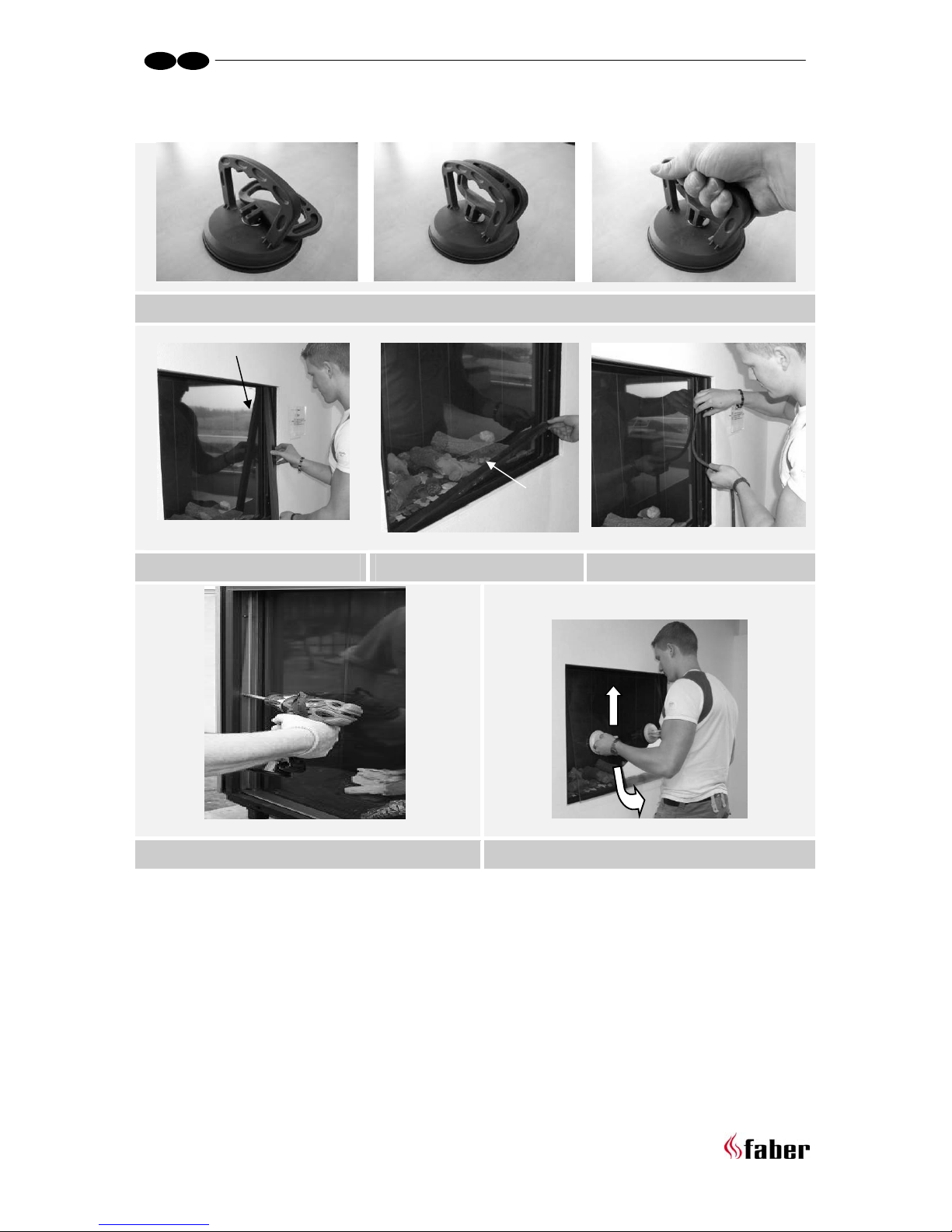
5 removing the glass.................................................................................11
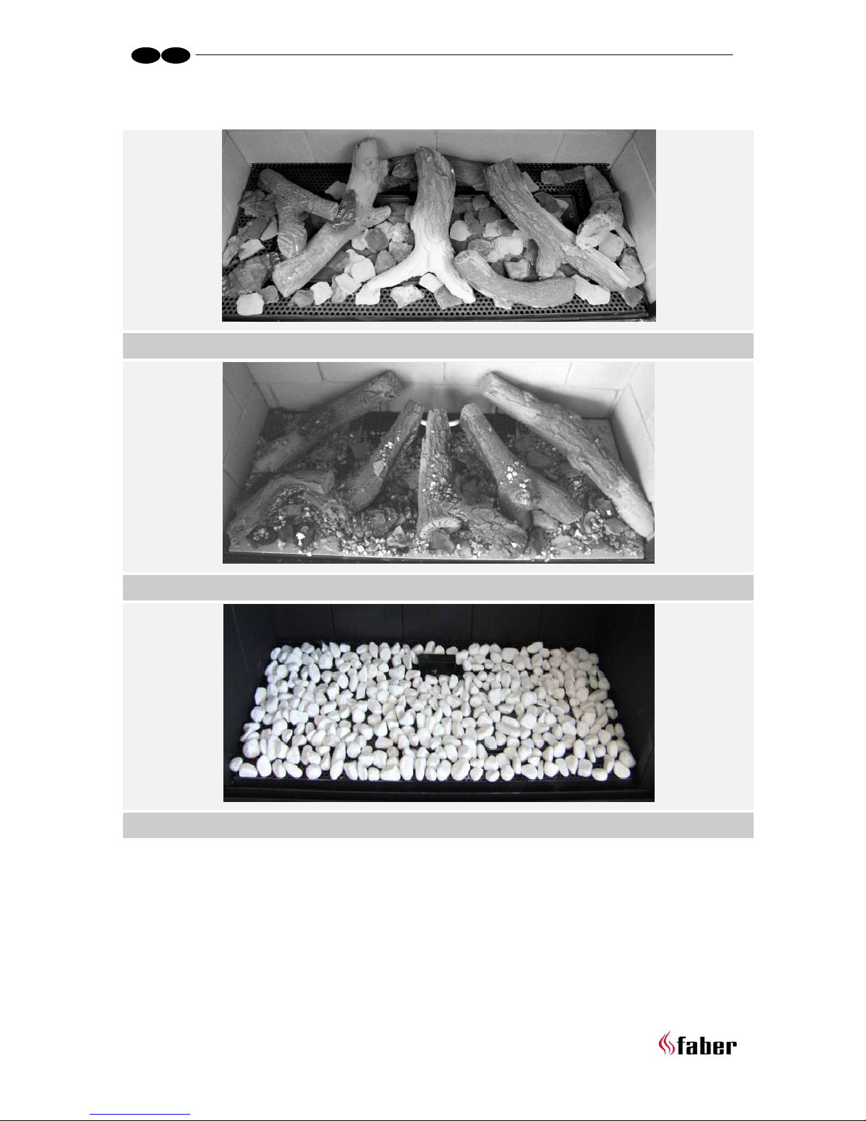
6 Placing the decorative material................................................................. 11
6.1 Imitation logs Flatburner ..................................................................11
6.2 Imitation logs Logburner...................................................................12
6.3 Pebbles ....................................................................................... 12
7 Checking the installation.........................................................................12
7.1 Checking the ignition of the pilot burner, main burner...............................12
7.2 Checking for gas leakage................................................................... 12
7.3 Checking the burner pressure and the pre-pressure ..................................13
7.4 Checking the flame picture................................................................13
8 Instructing the client..............................................................................14
9 Annual maintenance ..............................................................................14
9.1 Service and cleaning:.......................................................................14
9.2 Replace: ...................................................................................... 14
9.3 Cleaning the glass...........................................................................14
10 Conversion to a different type of gas (e.g. propane) ....................................15
11 Calculation of flue system....................................................................15

5 < < < <
11.1 Points of particular interest:..............................................................15
11.2 Sample computations.......................................................................16
12 Table............................................................................................. 17
12.1 Table Flatburner ............................................................................ 17
12.2 Table logburner .............................................................................18
13 Technical data.................................................................................. 19
13.1 Flatburner....................................................................................19
13.2 Logburner.....................................................................................20
14 Dimension of the appliance .................................................................. 21
15 Dimension of the surround Wirdum 770 ....................................................22
16 Dimension Ventilation Grills..................................................................23
17 Dimension Service Hatch......................................................................24

6 < < < <
1 Introduction
The appliance can only be installed by a competent person in accordance with the Gas
Safety. We urgently advise you to read this installation manual properly.
This appliance complies with the guidelines for European gas appliances (Gas Appliances
Directive) and bears the CE mark.
2 Safety instructions.
• The appliance should be placed, connected and annually checked in accordance
with these installation instructions and valid national and local Gas Safety
(Installation and Use) Regulations .
• Check whether the data on the registration plate are in agreement with the local
type of domestic gas and pressure.
• The fitter is not permitted to change these adjustments or the construction of the
appliance!
• Do not place any additional imitation logs or glowing coals on the burner or in the
combustion chamber.
• The appliance has been designed for ambience and heating purposes. This means
that all surfaces of the appliance , including the glass, can become very hot (hotter
than 100 °C). An exception to this are the bottom of the appliance and the
controls.
• Do not place any inflammable materials within a of 0.5 m. of the radiation of the
appliance and ventilation grills.
• Due to natural air circulation of the appliance, moisture and volatile components
from paint, building materials, floor coverings etc. that haven’t yet set, can be
drawn through the convection system and can be deposited on cold surfaces as
soot. That is why you should not use the appliance shortly after a renovation.
• The first time the appliance is switched on, Let the fire run on maximum setting for
several hours so that the lacquer coating will have an opportunity to set and
possible vapours released can be safely removed by ventilation. We advise you to
be outside the room as much as possible during this process!
• Please note that:
1 all transport packaging should be removed.
2 children or pets should not be present in the room.

7 < < < <
3 Installation requirements
3.1 The fire
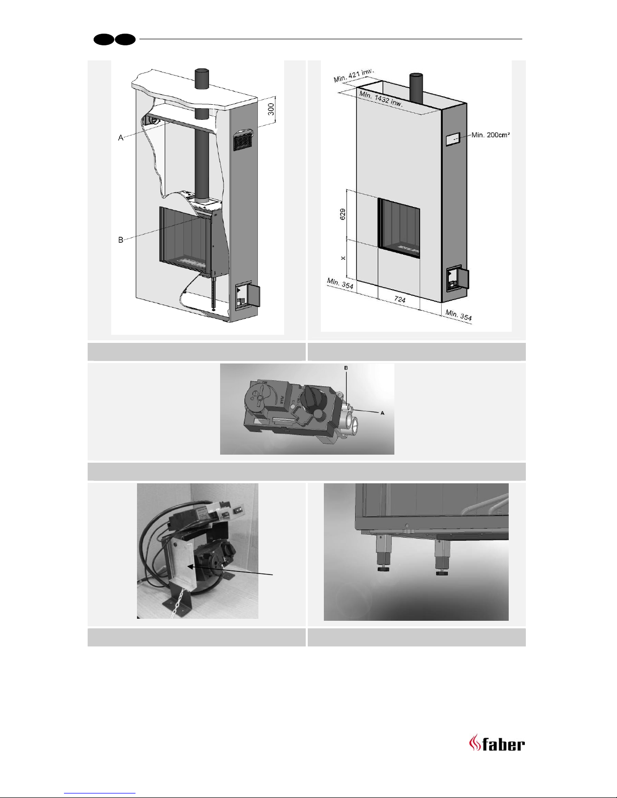
• The appliance must be built into an existing or a newly to be constructed false
chimney breast.
• In appliances with flexible gas pipes, the gas control valve is mounted to the right
side of the fire for safe transport . Unscrew it and mount it at a distance of max. 30
cm behind the access door.
• The receiver which has been attached in a transport holder (see fig. 1.4 A) to the
side of control valve bracket, can now be slid onto the top of the control valve
bracket. The transport holder can be removed now.
3.2 False Chimney breast
• The false chimney breast must be constructed of an non-combustible material.
• Always ventilate the space above the appliance by means of the grills or a
comparable alternative with a minimum air supply of 200 cm².
• For the finish, use special stucco (min. 100°C resistant) or glass fibre wallpaper to
prevent discoloration or cracks etc. Recommended drying time: for plaster is a
minimum of 24 hours per mm of coat applied.
• The false chimney breast and its construction may not rest on the appliance
3.3 Requirements flue system and outlets
• You should always make use of the materials prescribed by Faber International Ltd.
Only by using these materials can Faber International Ltd. guarantee a proper
functioning.
• The outside of the concentric flue material can reach a temperature of
Approx 150°C. Make sure of proper isulation and protection in case of transit
through combustible wall or ceiling constructions. And observe sufficient distance.
• Make sure that the concentric flue materials are bracketed every 2 metres when
they have an extended length, so that the weight of the flue material is not resting
on the appliance itself.
• You may never start with a cut-down concentric pipe directly on to the appliance.

8 < < < <
3.4 terminals
The flue outlet can end on an external wall or a roof . Check whether the outlet desired
by you complies with local requirements concerning good function and ventilation
systems .
For a proper functioning the terminal should be at least 0.5 m. away from:
• Corners of the building.
• Roof overhangs and balconies.
• Eaves (with the exception of the roof ridge).
3.5 Existing chimney
You can also connect the appliance to an existing chimney. The existing chimney will
function as an air supply and a flexible stainless steel pipe drawn up through the chimney
will remove the combustion gas.
The flexible stainless steel pipe of Ø 100 mm should have a CE mark for temperatures up to
600° Celsius.
The chimney should comply with the following requirements:
• The diameter of the flue system must be at least 150x150 mm.
• There should be no more than 1 appliance connected to a flue pipe.
• The chimney must be in good condition
o No leakage and
o It should be properly swept.
For more information about connections to existing flue systems, see the manual
“connections”.
 Loading...