

Page 1

O W N E R ’ S M A N U A L
MM OO DD EE LL LL AA 44 00 00
MM EE DD II UU MM DD UU TT YY SS WW II NN GG GG AA TT EE OO PP EE RR AA TT OO RR
Serial # Primary Arm
Serial # Secondary Arm
Serial # Box
Installation Date
2 YEAR WARRANTY
Page 2

2
OPERATOR SPECIFICATIONS
Tools Needed for Installation . . . . . . . . . . . . . . . . . . . . . . . . . . . . . . . . .2
Carton Inventory . . . . . . . . . . . . . . . . . . . . . . . . . . . . . . . . . . . . . . . . . .3
Additional Items Needed for Installation . . . . . . . . . . . . . . . . . . . . . . . .3
Operator Dimensions and Specifications . . . . . . . . . . . . . . . . . . . . . . . .3
Model Classifications . . . . . . . . . . . . . . . . . . . . . . . . . . . . . . . . . . . . . . .4
OPERATOR WARNINGS
Safety Installation Information . . . . . . . . . . . . . . . . . . . . . . . . . . . . . . . .5
Suggested Entrapment Protection Device Locations . . . . . . . . . . . . . .6
Warnings and Precautions . . . . . . . . . . . . . . . . . . . . . . . . . . . . . . . . . . .7
Warning Sign Placement . . . . . . . . . . . . . . . . . . . . . . . . . . . . . . . . . . . .7
INSTALLATION
Gate Setup . . . . . . . . . . . . . . . . . . . . . . . . . . . . . . . . . . . . . . . . . . . . . . .8
Pull-to-Open Mounting Installation . . . . . . . . . . . . . . . . . . . . . . . . . . . . .9
Push-to-Open Instructions for use with
Optional Accessory Kit 50-19503 . . . . . . . . . . . . . . . . . . . . . . . . . .10-11
Control Box Mounting . . . . . . . . . . . . . . . . . . . . . . . . . . . . . . . . . . . . . .12
WIRING
Connect Arm to Control Box . . . . . . . . . . . . . . . . . . . . . . . . . . . . . . . .13
Earth Ground Rod Installation . . . . . . . . . . . . . . . . . . . . . . . . . . . . . . .13
Control Wiring . . . . . . . . . . . . . . . . . . . . . . . . . . . . . . . . . . . . . . . . . . .14
BASIC CONTROL BOARD SETUP
Set Dip Switch for Gate Type . . . . . . . . . . . . . . . . . . . . . . . . . . . . . . . .16
Programming Remote . . . . . . . . . . . . . . . . . . . . . . . . . . . . . . . . . . . . .16
Wire Stop Button . . . . . . . . . . . . . . . . . . . . . . . . . . . . . . . . . . . . . . . . .17
Optional Control Devices . . . . . . . . . . . . . . . . . . . . . . . . . . . . . . . .18-20
Force and Timer to Close . . . . . . . . . . . . . . . . . . . . . . . . . . . . . . . . . .21
Program Limits . . . . . . . . . . . . . . . . . . . . . . . . . . . . . . . . . . . . . . . . . . .21
DIP Switch Settings . . . . . . . . . . . . . . . . . . . . . . . . . . . . . . . . . . . . . . .22
OPERATION AND MAINTENANCE
Maintenance . . . . . . . . . . . . . . . . . . . . . . . . . . . . . . . . . . . . . . . . . . . .23
Battery Replacement . . . . . . . . . . . . . . . . . . . . . . . . . . . . . . . . . . . . . .24
Manual Release . . . . . . . . . . . . . . . . . . . . . . . . . . . . . . . . . . . . . . . . . .25
ACCESSORIES
. . . . . . . . . . . . . . . . . . . . . . . . . . . . . . . . . . . . . . .25
WIRING DIAGRAM
. . . . . . . . . . . . . . . . . . . . . . . . . . . . . . . . . . .26
TROUBLESHOOTING
. . . . . . . . . . . . . . . . . . . . . . . . . . . . . .27-28
REPAIR PARTS
. . . . . . . . . . . . . . . . . . . . . . . . . . . . . . . . . . . .29-30
When you see these Safety Symbols and Signal Words on the following
pages, they will alert you to the possibility of serious injury or death if
you do not comply with the warnings that accompany them. The hazard
may come from something mechanical or from electric shock. Read the
warnings carefully.
When you see this Signal Word on the following pages, it will alert you
to the possibility of damage to your gate and/or the gate operator if you
do not comply with the cautionary statements that accompany it. Read
them carefully.
Mechanical
Electrical
TABLE OF CONTENTS
TABLE OF CONTENTS
WARNING
WARNING
WARNING
CAUTION
WARNING
WARNING
IMPORTANT NOTE
• BEFORE attempting to install, operate or maintain the operator, you
must read and fully understand this manual and follow all safety
instructions.
• DO NOT attempt repair or service of your commercial door and gate
operator unless you are an Authorized Service Technician.
WARNING
TOOLS NEEDED FOR INSTALLATION
During assembly, installation and adjustment of the operator the tools
listed below will be needed.
• Wrench or Socket Set
• Phillips Head Screwdriver
• C Clamps
• Level
• Small Screwdriver
• T25 Torx Head Screwdriver
Page 3
3
HARDWARE KIT LA400 (K77-19130)
DESCRIPTION QTY
Post Bracket 1
Pull to Open Bracket 1
5/16"-18 X 1-1/2" Hex Bolt 5
3/8"-16 X 6" Square Neck Carriage Bolt 2
3/8"-16 Hex Nut 5
5/16"-18 Hex Nut 5
5/16" Flat Washer 5
3/8" Flat Washer 5
5/16" Lock Washer 5
3/8" Lock Washer 5
Gate Mounting Bracket 1
Hairpin Clip 4
Pin 2
3/8"-16 X 1-1/2" Hex Bolt 1
2-3/4" Bolt 2
CONTROL BOX LA400 (LA-CONTROL)
DESCRIPTION QTY
Control Box 1
Hardware Bag 1
MISCELLANEOUS
Linear Actuator Arm - Model LA400-1K (1) or 2 (LA400-2K)
Warning Sign 2
Battery 2
Plug-In Transformer-24Vac 1
LA400-S
Extension Cable - Six Conductor 40'
Junction Box - IP56 1
Philips Head Mounting Screws 4
Anchors 4
Terminal Block - Twelve Connectors 1
NOTE: Carton inventory is based on a Single Operator. For Primary (Gate 1) and Secondary (Gate 2) installation the carton inventory is
doubled except for control box (1).
Main Supply (Motor) 24VDC
Current Consumption 2A
Power Consumption 48 Watts
Battery Charger Supply 26Vac, 29VA
Solar Panel Supply (Optional) 27.4V, 9W (Minimum)
Maximum Gate Width 16 ft. (4.9 m)
Maximum Gate Weight 550 Lbs.
Protection Class NEMA 3R
Travel Speed 14-18 seconds for a 90 degree opening
Rated Operating Time 4 Minutes
Temperature -20˚C to + 50˚C
-4˚F to + 122˚F
Main Supply (Control) Dedicated Circuit 120V~/60Hz
Absorbed Power 0.75 Watts
Protection Fuse Gate 1 ATC 15A
Protection Fuse Gate 2 ATC 15A
Protection Fuse Battery ATC 20A
Permanent fasteners for warning sign
Earth Ground Rod (Optional)
Power Wire: 120Vac (Stranded Copper Wire) Power Wire: 24Vac Transformer (Stranded Copper Wire)
Wire Guage Length Wire Guage Length
16 100' (30 m) 14 500' (152 m)
10 1000' (305 m) 12 1000' (305 m)
OR
CARTON INVENTORY
ADDITIONAL ITEMS NEEDED FOR INSTALLATION
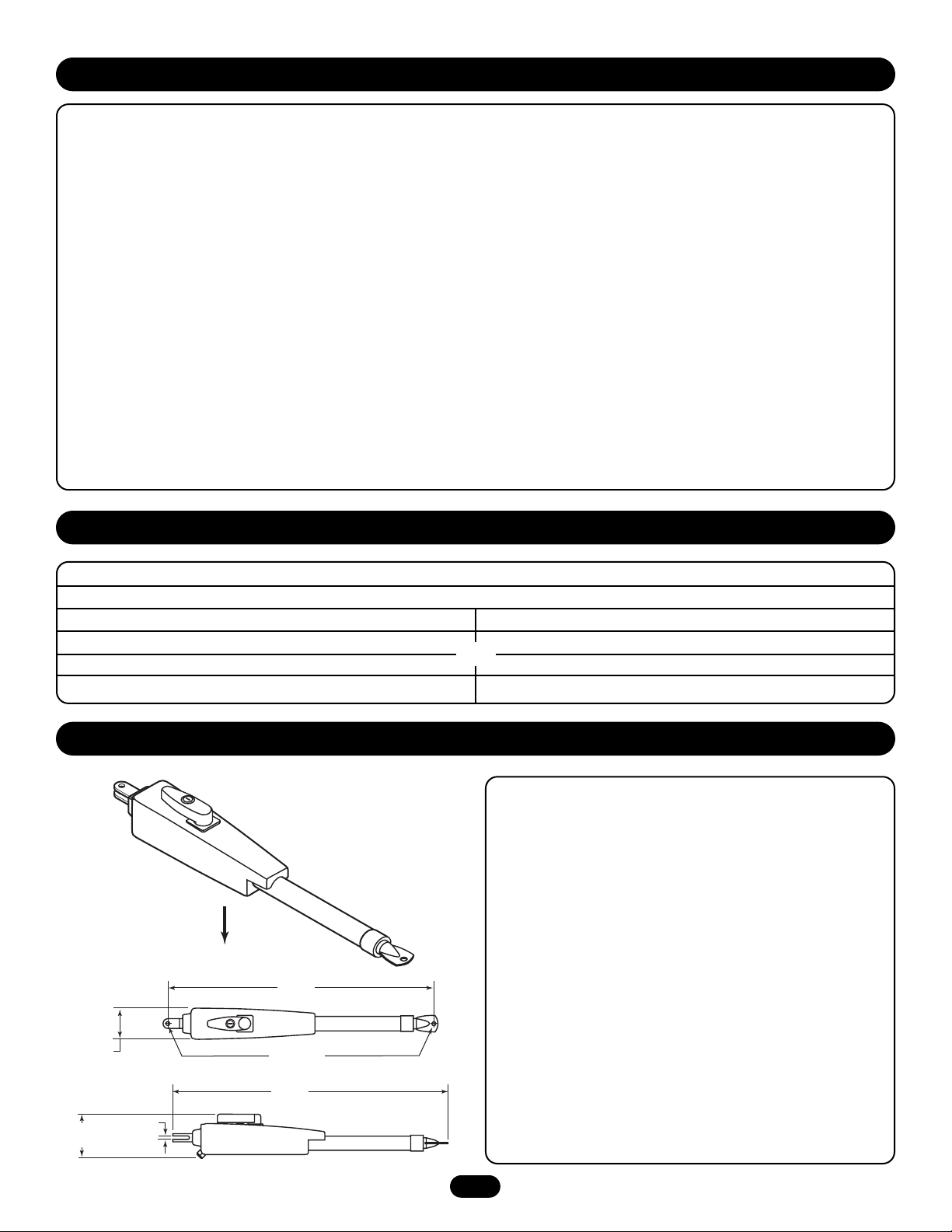
OPERATOR DIMENSIONS AND SPECIFICATIONS
4.00"
(10.2 cm)
4.50"
(11.2 cm)
Weight: 47Lbs. (21 kg.)
32.10"
(81.5 cm)
.475" DIA.
(1.2 cm DIA.)
33.25"
(84.5 cm)
.250"
(635 cm)
Page 4
4
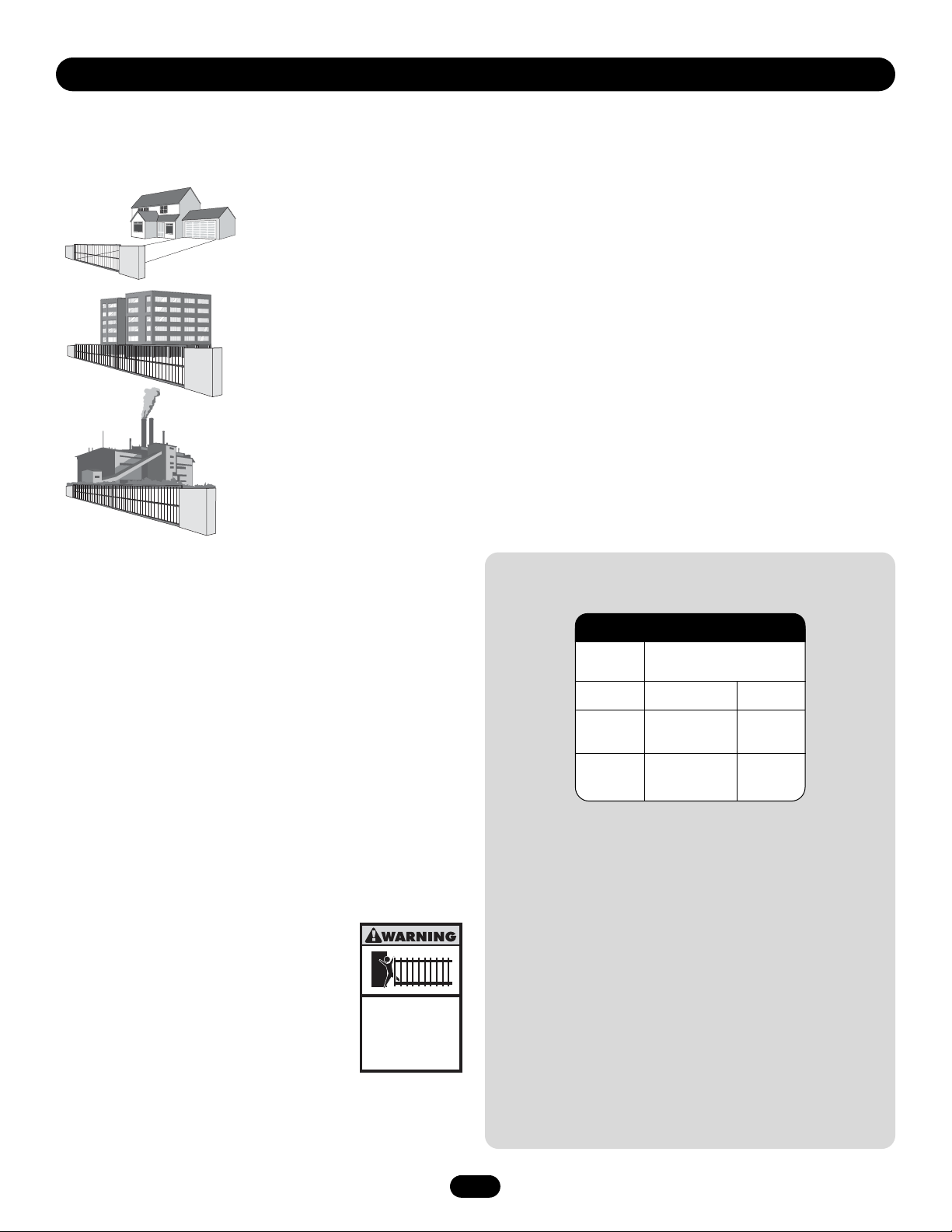
The LA400 is intended for use with vehicular swing gates.The opener can be used in Class I, Class II and Class III applications.
CLASS I – RESIDENTIAL VEHICULAR GATE OPERATOR
A vehicular gate operator (or system) intended for use in a home of one-to four single family dwelling, or a garage
or parking area associated therewith.
CLASS II – COMMERCIAL/GENERAL ACCESS VEHICULAR GATE OPERATOR
A vehicular gate operator (or system) intended for use in a commercial location or building such as a multi-family
housing unit (five or more single family units) hotel, garages, retail store or other building servicing the general
public.
CLASS III – INDUSTRIAL/LIMITED ACCESS VEHICULAR GATE OPERATOR
A vehicular gate operator (or system) intended for use in a industrial location or building such as a factory or
loading dock area or other locations not intended to service the general public.
SAFETY ACCESSORY SELECTION
All UL325 compliant LiftMaster gate operators will accept external
entrapment protection devices to protect people from motorized gate
systems. UL325 requires that the type of entrapment protection
correctly matches each gate application. Below are the four types of
entrapment protection systems recognized by UL325 for use on this
operator.
ENTRAPMENT PROTECTION TYPES
Type A: Inherent obstruction sensing system, self-contained within the
operator. This system must sense and initiate the reverse of
the gate within two seconds of contact with a solid object.
Type B1: Connections provided for a non-contact device, such as a
photoelectric eye can be used as a secondary protection.
Type B2: Connections provided for a contact sensor. A contact device
such as a gate edge can be used for secondary protection.
Type E: Built-in audio alarm. Examples include sirens, horns or
buzzers.
NOTE: UL requires that all installations must have
warning signs placed in plain view on both sides of
the gate to warn pedestrians of the dangers of
motorized gate systems.
UL325 ENTRAPMENT PROTECTION
REQUIREMENTS
The chart above illustrates the entrapment protection requirements
for each of the three UL325 classes.
In order to complete a proper installation you must satisfy the
entrapment protection chart shown above. That means that the
installation must have one primary means of entrapment protection
and one independent secondary means of entrapment protection.
Both primary and secondary entrapment protection methods must
be designed, arranged or configured to protect against entrapments
in both the open and close directions of gate travel.
For Example: For a slide gate system that is installed on a
single-family residence (UL325 Class I) you must provide the
following: As your primary type of entrapment protection you must
provide Type A inherent (built into the operator) entrapment sensing
and at least one of the following as your secondary entrapment
protection: Type B1- Non-contact sensors such as photoelectric
eyes, Type B2- Contact sensors such as gate edges.
Primary
Type
Class
I and II
Class III
A, B1 or B2
A, B1,
B2 or E
A, B1 or
B2
A
UL325 Swing and Gate Barrier
Installation (Arm) Operator
Secondary
Type
Gate Operator Entrapment Protection
Class
UL325 MODEL CLASSIFICATIONS
Moving Gate Can Cause
Injury or Death
KEEP CLEAR! Gate may move at any
time without prior warning.
Do not let children operate the gate or
play in the gate area.
This entrance is for vehicles only
Pedestrians must use separate entrance
Page 5

5
1. Vehicular gate systems provide convenience and security. Gate systems are comprised of many component parts. The gate operator is only
one component. Each gate system is specifically designed for an individual application.
2. Gate operating system designers, installers and users must take into account the possible hazards associated with each individual application.
Improperly designed, installed or maintained systems can create risks for the user as well as the bystander. Gate systems design and
installation must reduce public exposure to potential hazards.
3. A gate operator can create high levels of force in its function as a component part of a gate system. Therefore, safety features must be
incorporated into every design. Specific safety features include:
• Gate Edges • Guards for exposed rollers • Photoelectric Sensors
• Screen Mesh • Vertical Posts • Instructional and Precautionary Signage
4. Install the gate operator only when:
a. The operator is appropriate for the construction and the usage class of the gate.
b. All openings of a horizontal swing gate are guarded or screened from the bottom of the gate to a minimum of
4' (1.2 m) above the ground to prevent a 2 1/4" (57.15 mm) diameter sphere from passing through the openings anywhere in the gate, and in
that portion of the adjacent fence that the gate covers in the open position.
c. All exposed pinch points are eliminated or guarded, and guarding is supplied for exposed rollers.
5. The operator is intended for installation only on gates used for vehicles. Pedestrians must be supplied with a separate access opening.
6. The gate must be installed in a location so that enough clearance is supplied between the gate and adjacent structures when opening and
closing to reduce the risk of entrapment. Swinging gates shall not open into public access areas.
7. The gate must be properly installed and work freely in both directions prior to the installation of the gate operator.
8. Controls must be far enough from the gate so that the user is prevented from coming in contact with the gate while operating the controls.
9. Controls intended to be used to reset an operator after 2 sequential activations of the entrapment protection device or devices must be located
in the line of sight of the gate, or easily accessible controls shall have a security feature to prevent unauthorized use.
10. All warning signs must be installed where visible, on each side of the gate.
11. For a gate operator utilizing a non-contact sensor:
a. Reference owner’s manual regarding placement of non-contact sensor for each type of application.
b. Care shall be exercised to reduce the risk of nuisance tripping, such as when a vehicle trips the sensor while the gate is still moving.
c. One or more non-contact sensors shall be located where the risk of entrapment or obstruction exists, such as the perimeter reachable by a
moving gate or barrier.
12. For a gate operator utilizing a contact sensor such as an edge sensor:
a. A hard wired contact sensor shall be located and its wiring arranged so the communication between the sensor and the gate operator is not
subject to mechanical damage.
b. A wireless contact sensor such as the one that transmits radio frequency (RF) signals to the gate operator for entrapment protection
functions shall be located where the transmission of the signals are not obstructed or impeded by building structures, natural landscaping or
similar obstruction. A wireless contact sensor shall function under the intended end-use conditions.
c. One or more contact sensors shall be located at the leading edge, trailing edge and post mounted both inside and outside of a vehicular
horizontal slide gate.
d. One or more contact sensors shall be located at the bottom edge of a vehicular vertical lift gate.
e. One or more contact sensors shall be located on the inside and outside leading edge of a swing gate. Additionally, if the bottom edge of a
swing gate is greater than 6" (152mm) above the ground at any point in its arc of travel, one or more contact sensors shall be located on the
bottom edge.
SAFETY INSTALLATION INFORMATION
Page 6
6
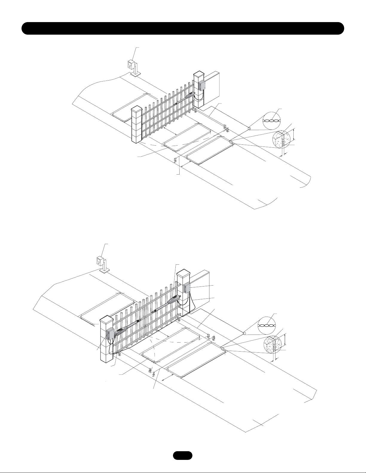
SWING GATE SYSTEM
DUAL SWING GATE SYSTEM
SUGGESTED ENTRAPMENT PROTECTION DEVICE LOCATIONS
Shadow loop should be positioned in direction
of gate travel. Pull-to-open illustrated.
The shadow loop input is only active when the
gate is in the fully open or fully closed positions.
STREET
Telephone
Entry System
Interrupt
Loop
Photo Eye for
Close Cycle
4' (1.2 m)
Typical
Shadow
Loop
4' (1.2 m)
Typical
Interrupt
Loop
Photo Eye for
Open Cycle
COMPLEX
OR
PARKING LOT
Run Twisted Wire*
from Loop to Operator
Seal Loops*
1-1/2"
(37 mm)
Loop Wire Layer*
1/4" (6 mm) or larger
depending on Loop
Wire size
STREET
Interrupt
Control
Box
Gate 1
Shadow loop should be positioned in direction
of gate travel. Pull-to-open illustrated.
The shadow loop input is only active when the
gate is in the fully open or fully closed positions.
Telephone
Entry System
Loop
Photo Eye for
Close Cycle
4' (1.2 m)
Typ
Shadow
Loop
4' (1.2 m)
Typical
ical
Gate 2
Interrupt
Loop
Junction
Box
Extension Cable
Photo Eye for
Open Cycle
COMPLEX
OR
Run Twisted Wire*
from Loop to Operator
Seal Loops*
1-1/2"
(37 mm)
Loop Wire Layer*
1/4" (6 mm) or larger
depending on Loop
Wire size
PARKING LOT
Page 7
7
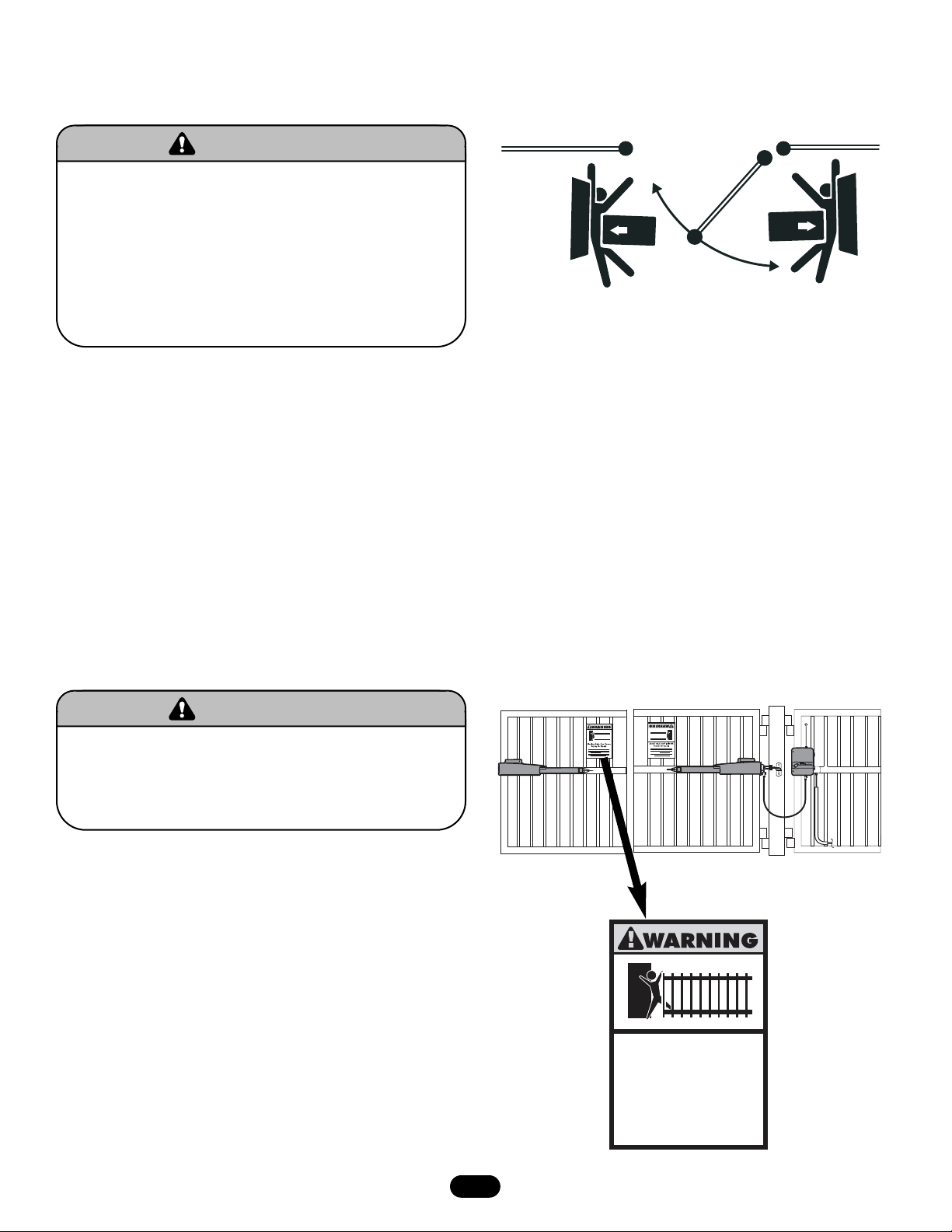
WARNING SIGN PLACEMENT
SAFETY PRECAUTIONS FOR SWING AND
ORNAMENTAL “GRILL TYPE GATES”
To prevent SERIOUS INJURY or DEATH from a moving gate:
• Install warning signs on EACH side of gate in PLAIN VIEW.
• Permanently secure each warning sign in a suitable manner
using fastening holes.
WARNING
WARNING
To prevent SERIOUS INJURY or DEATH from a moving gate:
• Entrapment protection devices MUST be installed to protect
anyone who may come near a moving gate.
• Locate entrapment protection devices to protect in BOTH the
open and close gate cycles.
• Locate entrapment protection devices to protect between
moving gate and RIGID objects, such as posts.
• A swinging gate shall NOT open into public access ways.
WARNING
WARNING
Moving Gate Can Cause
Injury or Death
KEEP CLEAR! Gate may move at any
time without prior warning.
Do not let children operate the gate or
play in the gate area.
This entrance is for vehicles only
Pedestrians must use separate entrance
Page 8
8
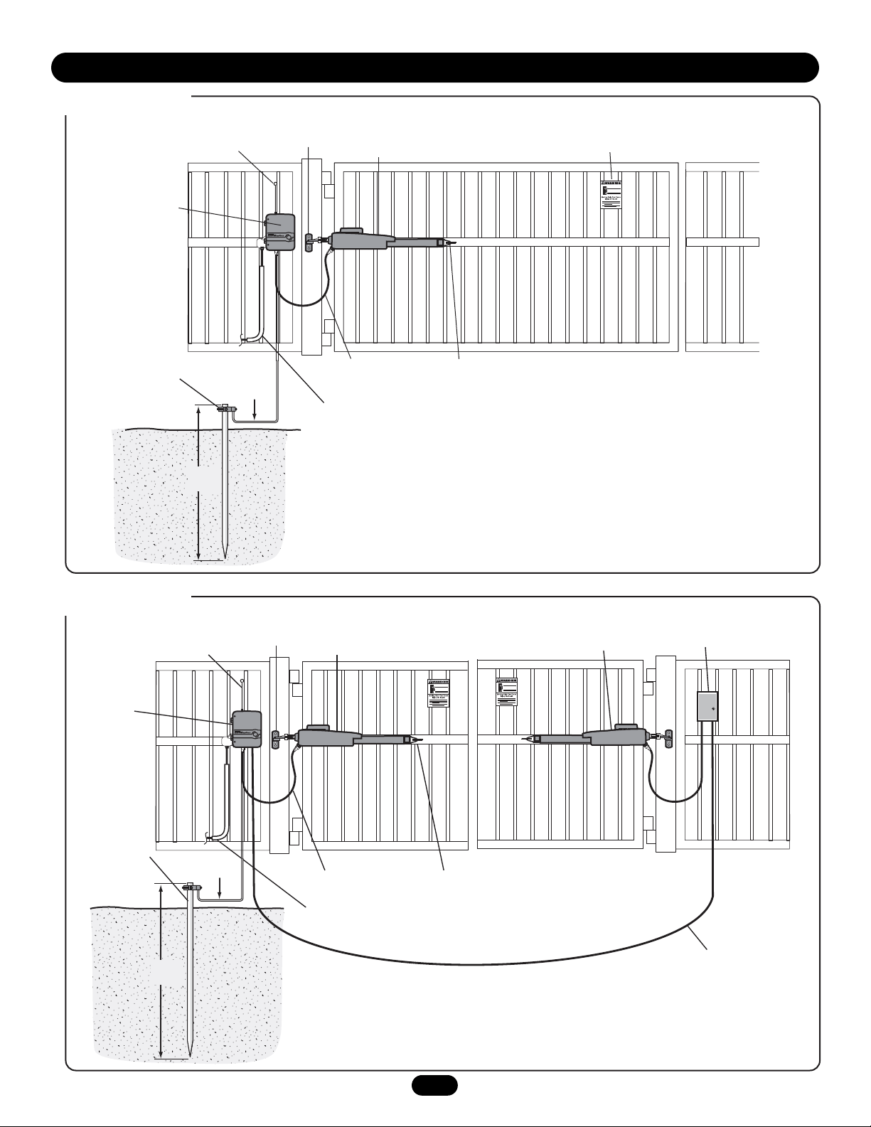
SINGLE GATE SETUP
INSTALLATION
Control Box
with Batteries
Earth Ground
Installation
(Optional,
See Page 13)
Antenna
12 gauge wire
8 ft.
(2.4 m)
Post Bracket Assembly
Gate Operator
4 1/2' (1.4 m)
Power Cable
PVC conduit (not included)
to protect the power cable
and low voltage wire from
lawn mowers and string trimmer.
Warning Sign
Gate Bracket
DUAL GATE SETUP
Control Box
with Batteries
Earth Ground
Installation
(Optional,
See Page 13)
8 ft.
(2.4 m)
Antenna
12 gauge wire
Post Bracket Assembly
Gate Operator 1
PVC conduit (not included) to protect the power cable
and low voltage wire from lawn mowers and string trimmer.
4 1/2' (1.4 m)
Power Cable
Gate Bracket
Gate Operator 2
Junction Box
Extension Cable
Page 9
9
Post Bracket
Assembly
C Clamp
Fence
Post
Gate In
OPEN Position
Vertical Center
of Gate
Cross Member
3/8" Hex Bolt
3/8" Washer
3/8" Lock Washer
3/8" Nut
Pull-to-Open
Bracket
Post Bracket
5/16" Washer
5/16" Lock Washer
5/16" Nut
5/16" Hex Bolt
Center of Gate Hinge
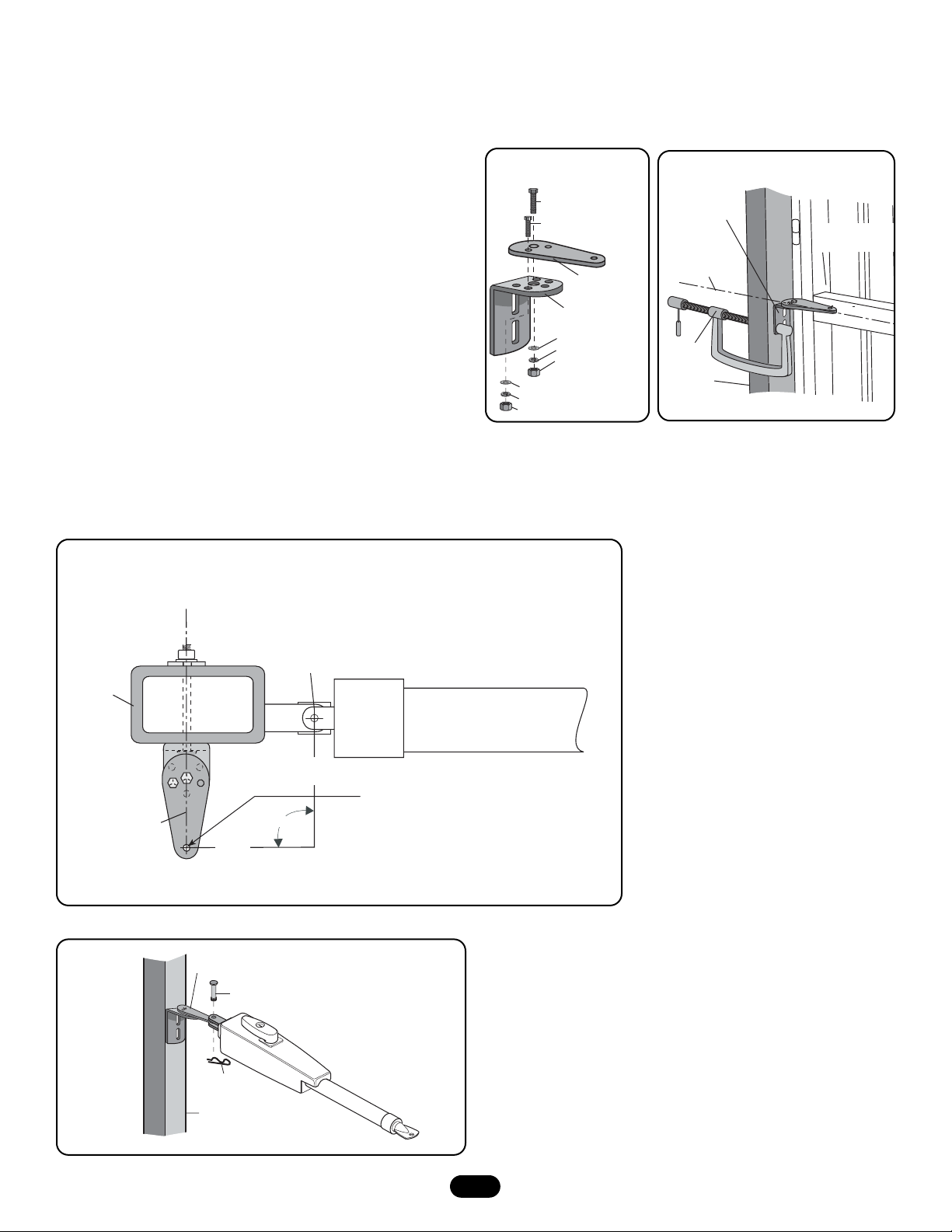
PULL-TO-OPEN INSTALLATION
Gate Post
Closed Gate
7-3/4"
(19.7 cm)
7-3/4"
(19.7 cm)
NOTE: You may want to drive a stake in
the ground to help locate this point.
Bracket must
be straight
90°
Figure 2
Figure 3
NOTE: The mounting illustrations represent a typical installation using the provided gate hardware.The gate opener may also be installed by
welding it to the gate structure. For push-to-open installation order accessory kit 50-19503.
Figure 1
1. Place pull-to-open bracket on top of the post bracket. Insert 3/8"
hex bolt through middle hole and secure with lock washer, flat
washer and nut. Insert 5/16" hex bolt through hole in pull-to-open
bracket and post bracket. Secure with washer, lock washer and nut
(Figure 1.)
NOTE: Do not pivot bracket, bracket must be straight or you may
damage your gate, operator or gate post bracket.
2. Determine the vertical position of the gate post bracket assembly
on the gate post by aligning the gate post bracket with one of the
cross members of the gate. For optimal performance, align the gate
post bracket to a cross member that is as close to the vertical
center of the gate post as possible. Level gate post bracket
assembly and temporarily secure to gate post using C clamp
(Figure 2.)
3. Move the gate post bracket assembly to obtain desired dimensions
(Figure 3).
4. Attach operator to gate post bracket by inserting pull-to-open
bracket into slot on the motor side of operator. Temporarily secure
with pin (Figure 4.)
Pin
Gate Post
Post Bracket
Hairpin Clip
Figure 4
PULL-TO-OPEN BRACKET MOUNTING INSTRUCTIONS
Page 10
10
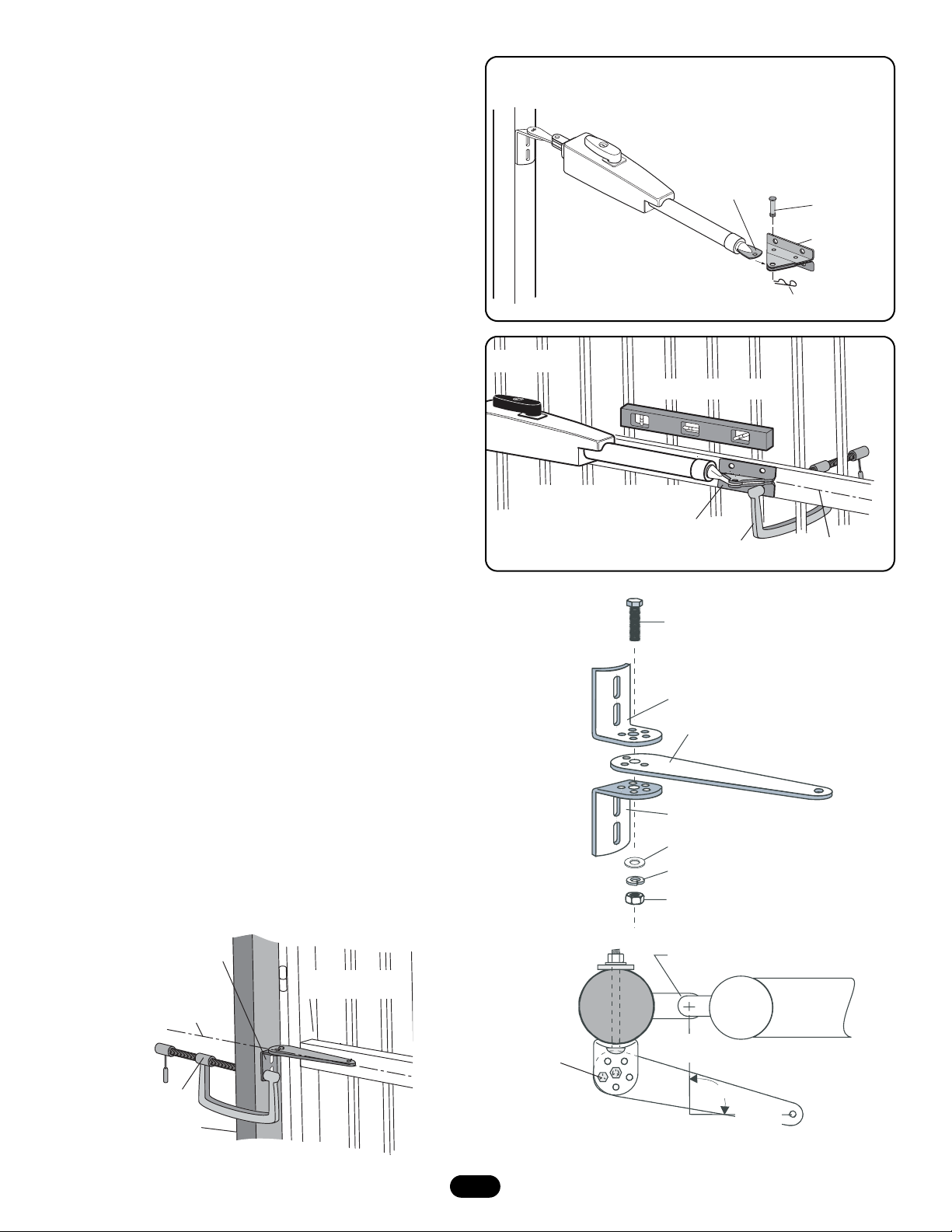
PUSH-TO-OPEN BRACKET MOUNTING
INSTRUCTIONS (FOR USE WITH ACCESSORY KIT
50-19503)
1. Place push-to-open bracket between the two post brackets. Insert
3/8" hex bolt through middle hole and secure with lock washer, flat
washer and nut (Figure 1.)
2. Determine the vertical position of the gate post bracket assembly
on the gate post by aligning the gate post bracket with one of the
cross members of the gate (Figure 2.) For optimal performance,
align the gate post bracket to a cross member that is as close to
the vertical center of the gate post as possible. Level gate post
bracket, mark holes and temporarily secure to gate post using C
clamp (Figure 2.)
3. Rotate the push-to-open bracket to obtain desired dimensions
(Figure 3.)
Figure 1
Figure 3
5. Fasten gate bracket to the actuator side of the operator using pin.
Swing operator to the desired open position (Figure 5).
6. Open gate to full open position (Do not exceed 100°). Adjust
operator until it is level and position bracket against the cross
member. Secure using C clamp (Figure 6).
7. Remove pins and detach operator.
8. Mark holes for post bracket assembly and gate bracket. Be sure to
mark holes in the vertical center of post bracket slots.
NOTE: All four gate bracket mounting holes must be used.
9. Remove brackets from gate post and cross member.
10. Drill 13/32" holes in marked locations for gate posts and 11/32" for
gate bracket.
11. Secure gate posts bracket assembly to gate post using 3/8" bolts,
lock washer, flat washer and nuts. Secure gate bracket to cross
member using 5/16" bolts, lock washer, flat washer and nuts.
12. Reattach operator to gate using pins and hairpin clips.
NOTE: After final limit adjustments (page 21) the gate can be opened
slightly further by increasing the distance between center of gate hinge
and the gate bracket by 1" (25 mm). Do not move the post bracket
assembly.
Gate In OPEN Position
Gate Bracket
C Clamp
Operator MUST be level
Vertical Center of
Gate Cross Member
Figure 6
Pin
Gate Bracket
Actuator Side
Hairpin Clip
Figure 5
Post Bracket
Assembly
C Clamp
Fence
Post
Gate In
CLOSED Position
Vertical Center
of Gate
Cross Member
Figure 2
5/16" Hex Bolt
3/8" Hex Bolt
Post Bracket
Push-to-Open Bracket
Post Bracket
3/8" Flat Washer
3/8" Lock Washer
3/8" Nut
Center of Gate Hinge
7-3/4"
(19.7 cm)
90˚
7-3/4"
(19.7 cm)
Special Post Pivot Bracket for
Push-to-Open Installation
Page 11

Figure 4
11
7. Remove pins and detach operator.
8. Mark holes for post bracket assembly and gate bracket. Be sure to
mark holes in the vertical center of post bracket slots.
NOTE: All four mounting holes must be used.
9. Remove brackets from gate post and cross member.
10. Drill 13/32" holes in marked locations for gate posts and 11/32" for
gate bracket.
11. Secure gate posts bracket assembly to gate post using 3/8" bolts,
lock washer, flat washer and nuts. Secure gate bracket to cross
member using 5/16" bolts, lock washer, flat washer and nuts
(Figures 6 & 7).
12. Reattach operator to gate using pins and hairpin clips.
NOTE: After final limit adjustments (page 21) the gate can be closed
slightly further by increasing the distance between center of gate hinge
and the gate bracket by 1" (25 mm). Do not move the post bracket
assembly.
Figure 6
Figure 7
Figure 5
4. Attach operator to gate post bracket by inserting push-to-open
bracket into slot on the motor side of operator. Secure with pin
(Figure 4.)
5. Fasten gate bracket to the actuator side of the operator using pin.
Swing operator to the desired closed position (Figure 4).
6. Position gate to full closed position. Adjust operator until it is level
and position bracket against the cross member. Secure using C
clamp (Figure 5).
Push-to-Open Bracket
Lock Washer
Pin
Hex Bolt
Post Bracket
Flat Washer
Nut
Hairpin Clip
Pin
Gate Bracket
Hairpin Clip
Gate In Open Position
LEVEL Horizontal Cross Member
Mark cross member through middle of
gate bracket slots and drill 11/32" holes
Post Bracket
Assembly
C Clamp
Fence Post
Operator MUST be level
Gate In CLOSED Position
Gate Bracket
C Clamp
Mark fence post through
middle of bracket slots
and drill 13/32" holes
Post Bracket
Assembly
3/8"-16 x 6"
Carriage Bolt
Vertical Center of
Gate Cross Member
Page 12

12
CONTROL BOX MOUNTING WITH U-BOLTS
(OPTIONAL KIT)
1. Determine the spacing required for mounting and select the proper
holes to be used for mounting (Figure 1).
2. Knockout plastic from holes using screw driver.
3. Center the box up against the mounting post. Insert the U-bolts
through the mounting holes in back (Figure 3).
4. Once the U-Bolts are in place, insert the rubber washer, followed by
the metal washer and 1/4-20 Nut (Figure 3).
5. Tighten the assembly down snug after positioning it as desired.
Optional kits available are:
50-19509 6" (15 cm) Post Mounting
50-19511 4" (10 cm) Post Mounting
50-19512 2-1/2" (6.3 cm) Post Mounting
CONTROL BOX MOUNTING
1. Determine the spacing required for mounting and select the proper
holes to be used for mounting (Figure 1).
2. Knockout plastic from holes using screw driver.
3. Place box up against the mounting surface. Insert the screws through
the mounting holes in back and secure in place (Figure 2).
4" (10 cm) Screw Spacing (4)
Mounting Post
Figure 2
Figure 1
6" (15 cm) Screw
Spacing (4)
2-1/2" (6.3 cm) Screw Spacing (4)
Figure 3
1/4" Washer (4)
1/4"-20
Hex Nut (4)
Mounting Post
E-Box
Mounting screw
4 places
U-Bolt (2)
1/4" Washer (4)
Page 13

13
120VAC POWER WIRE
(STRANDED COPPER WIRE)
NOTE: Calculated using NEC guidelines. Local codes and conditions must be reviewed for suitability of wire installation.
To reduce the risk of SEVERE INJURY or DEATH:
• ANY maintenance to the operator or in the area near the
operator MUST not be performed until disconnecting the
electrical power and locking-out the power via the operator
power switch. Upon completion of maintenance the area MUST
be cleared and secured, at that time the unit may be returned
to service.
• Disconnect power at the fuse box BEFORE proceeding.
Operator MUST be properly grounded and connected in
accordance with local electrical codes. NOTE: The operator
should be on a separate fused line of adequate capacity.
• ALL electrical connections MUST be made by a qualified
individual.
• DO NOT install any wiring or attempt to run the operator
without consulting the wiring diagram. We recommend that
you Install an optional reversing edge BEFORE proceeding with
the control station installation.
• ALL power wiring should be on a dedicated circuit and well
protected. The location of the power disconnect should be
visible and clearly labeled.
• ALL power and control wiring MUST be run in separate
conduit.
• BEFORE installing power wiring or control stations be sure to
follow all specifications and warnings described below. Failure
to do so may result in SEVERE INJURY to persons and/or
damage to operator.
Wire Gauge
16
10
Length
100' (30 m)
1000' (305 m)
WARNING
WARNING
EARTH GROUND ROD INSTALLATION (0PTIONAL)
When installing the optional earth ground rod, disconnect and remove
the green/yellow ground wire connected to the screw terminal of the
printed circuit board. For proper
operation, the earth ground rod
should not be connected to the
ground of your power wiring.
Ensure the power wiring ground
connection remains securely
connected to the green screw on
the outlet plate.
The earth ground rod must be
located within 3 feet (0.9 m) of
the operator. Use the proper type
earth ground rod for your area.
Attach earth ground rod wire to
the screw terminal of the printed
circuit board marked .
To AVOID damaging gas, power, or other underground utility
lines, contact underground utility locating companies BEFORE
digging more than 18" (46 cm) deep.
Earth Ground
Installation
12 gauge
wire
8 ft.
(2.4 m)
Control Box
WARNING
CAUTION
WARNING
WARNING
All power wiring should be on a dedicated circuit and well protected.
24VAC TRANSFORMER
(STRANDED COPPER WIRE)
Wire Gauge
14
12
Length
500' (152 m)
1000' (305 m)
The transformer is tie-wrapped at the factory for shipping.The
transformer can be plugged into a receptacle external to the control
box.You can run low voltage wire between the transformer and control
box.
Alternatively, you can connect 120VAC directly to the box, and plug the
transformer to the receptacle inside the control box.
CONNECT ARM TO CONTROL BOX
Connect the wires from the operator to connector P17 for the Gate 1
operator as shown in the wiring diagram on page 26. Connect the
proper color coded wire to the terminal pin as indicated.
If connecting a second arm, follow the same instructions on
connector P16.
WIRING
Motor
Wiring
Control
Wiring
Power
Wiring
Page 14

14
MOV2
24 VAC/
SOLAR
INPUT
J4
B
ATT
2
BATT
1
BATTERY
The main source of power for the operator is the batteries. The
batteries can be charged in circuit by using a charging
transformer or solar panels.
CONTROL WIRING
CHARGING
The 24VAC input can accept a charging transformer
(26VAC, 29VA).
SOLAR PANELS
Optional solar panels may be used to charge the batteries. Solar
Panels (LA400-SPK) must be a minimum of 27.4V, 9W output.
To reduce the risk of FIRE or INJURY to persons use only
Chamberlain part #K74-30762 for replacement batteries.
WARNING
CAUTION
WARNING
WARNING
ALARM
MAGLOCK
GATE 1
ACCESSORY
POWER
GATE 2
P2
R35
D9
Z3
Z4
JMPR1
SAVE
MAGLOCK
MODE
EDGE
PHOTO
BIPART
DELAY
U3
P1
TIMER
RUNNING
TIMER TO
CLOSE
F7
C13
D4
D1
D2
D6
J19
NO
C
NO
C
NC
Z1
BRN
GRN
WHT
YEL
BLU
RED
BRN
GRN
WHT
YEL
BLU
RED
C2R4
J4
K6
K5
L1
S8
1
R2
LEARN
XMITTER
10A 32V
Z12
R9
24V
D15
R196
24 VAC/
SOLAR
INPUT
R1
2
F3
Ø
D1
K2
SET
K1
Q9
OPEN
Ø
LIMIT
R1
Ø
1
ØØ
R1
F4
ACCESSORY
10A 32V
OVLD
K4
F5
D21
K3
D8
D22
Q22
MOV2
MOV1
JMPR2
DB1
Ø
14GPØ89ØE
Ø
14LGØ89ØE
Ø
14SKØ89ØE
J1
O
N
1 2 3 4 5
OFF
ON
OFF
ON
SINGLE
DUAL
NO
NC
NO
NC
S1
DIAGNOSTIC
GATE 1
SET
LEARN
CLOSE
LIMITS
LIMIT
GATE 2
FORCE
MIN MAX OFF MAX OFF MAX
C12
D27
C11
R9
C64
U2
R223
CLOSE
Z22
R92
R91
R94
R93
OVLD
RESET
POWER
SHADOW
INTERRUPT
EDGE
OPEN EDGE/
PHOTO
OPEN
PHOTO
CLOSE
PHOTO
24V
SWITCHED
ACCESSORY
COM
OVLD
POWER
CONTROL
INPUTS
OPEN
STOP
COM
COM
LOOP
INPUTS
COM
BATT 1BATT 2
R2
Ø
7
Z2
Ø
R227
J18
R224
U4
SINGLE
BUTTON
SINGLE BUTTON
C4
CHGR
OVLD
F6
F2
Ø
A 32V
F1 2
FUSE
OPEN
Z9
Z8
USE DEDICATED CIRCUIT
OR
Page 15

15
ITEM DESCRIPTION FUNCTION
1 Connector P1 Antenna Input
2 Connector P6 Close Edge
3 Connector P8 Open Edge/Photo
4 Connector P7 Open Photo
5 Connector P9 Close Photo
6 Connector P12 Switched Accessory Power*
7 Connector P10 Control Inputs
8 Connector P11 Loop Inputs
9 Connector P5 24Vac/Solar Input
10 Connector P16 Gate 2
11 Connector P13 Accessory Power*
12 Connector P17 Gate 1
13 Connector P14 Maglock/Solenoid
*Maximum 300 mA combined output
ITEM DESCRIPTION FUNCTION
14 Connector P15 Alarm
15 Connector Battery 1
16 Connector Battery 2
17 Dip Switch S1
18 Pushbutton Learn Xmitter - Program Remote
19 Pushbuttons Gate 1 - Jog Learn Limit
20 Pushbutton Learn Limits
21 Pushbuttons Gate 2 - Jog Learn Limit
22 Pushbutton Single Button
23 Potentiometer Force
24 Potentiometer Bi-Part Delay
25 Potentiometer Timer to Close
26 Connector Receiver
BASIC CONTROL BOARD SETUP
14
13
18
12
11*
10
21
ALARM
MAGLOCK
GATE 1
ACCESSORY
POWER
GATE 2
J4
17
N
S1
CLOSE
O
1 2 3 4 5
ON
ON
DUAL
NC
NC
SET
LIMIT
D27
R9
Ø
14GPØ89ØE
Ø
14LGØ89ØE
Ø
14SKØ89ØE
GATE 1
LEARN
LIMITS
GATE 2
R35
D9
Z3
Z4
JMPR1
26
SAVE
MAGLOCK
MODE
EDGE
PHOTO
BIPART
DELAY
U3
D6
TIMER
RUNNING
D1
P2
D4
D2
P1
U4
TIMER TO
CLOSE
F7
C13
1
R223
CLOSE
24V
OVLD
BATT 1BATT 2
COM
COM
COM
EDGE
OPEN EDGE/
PHOTO
OPEN
PHOTO
CLOSE
PHOTO
SWITCHED
ACCESSORY
POWER
CONTROL
INPUTS
LOOP
INPUTS
2
3
Z9
4
Z8
5
6*
22
7
8
R2
Ø
7
Ø
Z2
R227
J18
R224
Z22
R92
R91
R94
R93
COM
SINGLE BUTTON
CHGR
OVLD
F1 2
FUSE
OPEN
POWER
SHADOW
INTERRUPT
0
A 32V
OVLD
OPEN
RESET
STOP
F6
F2
SINGLE
BUTTON
C4
20
K6
NO
C
NO
C
NC
Z1
10A 32V
BRN
GRN
WHT
YEL
BLU
RED
Z12
R9
Ø
24V
BRN
GRN
WHT
YEL
BLU
RED
D15
R196
C2R4
24 VAC/
SOLAR
INPUT
F3
Ø
D1
K1
10A 32V
MOV2
19
J19
J1
K5
L1
S8
1
R2
LEARN
XMITTER
R1
2
K2
SET
Q9
OPEN
LIMIT
Ø
1
R1
ØØ
R1
F4
K4
K3
Q22
OFF
OFF
SINGLE
NO
NO
DIAGNOSTIC
FORCE
ACCESSORY
OVLD
MIN MAX OFF MAX OFF MAX
F5
D21
D8
D22
DB1
JMPR2
MOV1
C12
C11
C64
U2
923242515
16
Page 16

16
S1
SAVE
MAGLOCK
MODE
EDGE
PHOTO
OFF
OFF
SINGLE
NO
NO
ON
ON
DUAL
NC
NC
1 2 3 4 5
O
N
SET DIP SWITCH FOR GATE TYPE
1. The Save switch must be set to the OFF position prior to setting or
changing the switches.
2. Set switch to Single for single gate installation. For Dual
(Gate 1 and 2) installation set switch on Dual.
3. Set the Save switch to ON to save the setting.
NOTE: When setting switches S2-5 the save switch must be in the off
position prior to setting or changing switches for the change to be
saved.
ALARM
MAGLOCK
GATE 1
ACCESSORY
POWER
GATE 2
P2
LIMITS
R35
D9
Z3
Z4
JMPR1
SAVE
MAGLOCK
MODE
EDGE
PHOTO
BIPART
DELAY
U3
P1
TIMER
RUNNING
TIMER TO
CLOSE
F7
C13
D4
D1
D2
D6
J19
NO
C
NO
C
NC
Z1
BRN
GRN
WHT
YEL
BLU
RED
Z12
BRN
GRN
WHT
YEL
BLU
RED
C2R4
J4
K6
K5
L1
S8
1
R2
LEARN
XMITTER
10A 32V
R9
24V
D15
R196
24 VAC/
SOLAR
INPUT
R1
2
F3
Ø
D1
K2
SET
K1
Q9
OPEN
Ø
LIMIT
R1
Ø
1
ØØ
R1
F4
ACCESSORY
10A 32V
OVLD
K4
F5
D21
K3
D8
D22
Q22
MOV2
MOV1
JMPR2
DB1
Ø
14GPØ89ØE
Ø
14LGØ89ØE
Ø
J1
DIAGNOSTIC
14SKØ89ØE
O
N
1 2 3 4 5
OFF
ON
OFF
ON
SINGLE
DUAL
NO
NC
NO
NC
S1
GATE 1
SET
LEARN
CLOSE
LIMIT
GATE 2
FORCE
MIN MAX OFF MAX OFF MAX
C12
D27
C11
R9
C64
U2
R223
CLOSE
Z22
R92
R91
R94
R93
RESET
POWER
SHADOW
INTERRUPT
EDGE
OPEN EDGE/
PHOTO
Z9
OPEN
PHOTO
Z8
CLOSE
PHOTO
24V
SWITCHED
ACCESSORY
COM
OVLD
POWER
OVLD
CONTROL
INPUTS
OPEN
OFF
OFF
STOP
COM
COM
LOOP
INPUTS
COM
BATT 1BATT 2
SINGLE
NO
NO
OFF
OFF
SINGLE
NO
NO
O
N
O
N
1 2 3 4 5
ON
ON
DUAL
NC
NC
1 2 3 4 5
ON
ON
DUAL
NC
NC
R2
Ø
7
Ø
Z2
R227
J18
R224
U4
SINGLE
BUTTON
SINGLE BUTTON
C4
CHGR
OVLD
F6
F2
F1 20A 32V
FUSE
OPEN
Page 17

17
COM
COM
CONTROL
INPUTS
OPEN
SINGLE BUTTON
RESET
STOP
POWER
WIRE STOP BUTTON (OPTIONAL)
A jumper wire is factory installed between the stop and common input.
Stop (N/C) - Stop only (does not reset alarm)
PROGRAMMING REMOTE
1. Press LEARN XMITTER button (LED will light up).
2. Press remote button, the LED will flash, alarm output will activate
twice.
3. Repeat steps 1 and 2 until all remotes are programmed
(50 remotes maximum).
NOTE: For highest level of security, we recommend the Security
✚
®
line
of products.
COMPATIBLE REMOTES - 315MHz
Passport Remote Security✚® Remotes
CPT13 370LM
CPT23 371LM
CPT33 372LM
Security✚
®
Keypad 373LM
376LM 374LM
R1
LEARN
XMITTER
2
L
i
f
t
M
a
s
t
e
r
L1
R1
R2
Z1
K5
Ø
14GPØ89ØE
Ø
14LGØ89ØE
Ø
14SKØ89ØE
K6
K2
F3
10A 32V
D1
Ø
P1
P2
J1
J19
S1
Q9
K1
Z12
MAGLOCK
ALARM
GATE 1
C
C
NC
NO
NO
GRN
WHT
YEL
BLU
RED
BRN
SET
OPEN
LIMIT
SET
CLOSE
LIMIT
LEARN
LIMITS
DIAGNOSTIC
GATE 1
SAVE
MAGLOCK
MODE
EDGE
PHOTO
OFF
OFF
SINGLE
NO
NO
ON
ON
DUAL
NC
NC
LEARN
XMITTER
S8
1 2 3 4 5
O
N
2
1
NOTICE: To comply with FCC and or Industry Canada (IC) rules, adjustment or
modifications of this receiver and/or transmitter are prohibited, except for changing the
code setting or replacing the battery. THERE ARE NO OTHER USER SERVICEABLE PARTS.
Tested to Comply with FCC Standards FOR HOME OR OFFICE USE. Operation is subject to
the following two conditions: (1) this device may not cause harmful interference, and
(2) this device must accept any interference received, including interference that may
cause undesired operation.
P2
R35
D9
Z3
Z4
BIPART
DELAY
SAVE
MAGLOCK
MODE
EDGE
PHOTO
U3
D6
RUNNING
D1
P1
J18
U4
TIMER
TIMER TO
CLOSE
F7
C13
C4
F6
F2
D4
D2
ALARM
NO
C
MAGLOCK
NO
C
NC
Z1
GATE 1
BRN
GRN
WHT
YEL
BLU
RED
Z12
ACCESSORY
POWER
GATE 2
BRN
GRN
WHT
YEL
BLU
RED
C2R4
J4
10A 32V
Ø
D1
R9
Ø
24V
D15
R196
24 VAC/
SOLAR
INPUT
MOV2
10A 32V
J19
K6
K5
L1
S8
1
R2
LEARN
XMITTER
R1
2
F3
K2
SET
K1
Q9
OPEN
LIMIT
R1
Ø
1
ØØ
R1
F4
ACCESSORY
OVLD
K4
F5
D21
K3
D8
D22
Q22
MOV1
JMPR2
DB1
Ø
14GPØ89ØE
Ø
14LGØ89ØE
Ø
14SKØ89ØE
J1
O
N
1 2 3 4 5
OFF
ON
OFF
ON
SINGLE
DUAL
NO
NC
NO
NC
S1
DIAGNOSTIC
GATE 1
SET
LEARN
CLOSE
LIMITS
LIMIT
GATE 2
FORCE
MIN MAX OFF MAX OFF MAX
C12
D27
C11
R9
C64
JMPR1
U2
SINGLE
BUTTON
R2
R224
FUSE
OPEN
Ø
7
F1 20A 32V
R223
Z2
Ø
R227
Z22
R92
R91
R94
R93
SINGLE BUTTON
RESET
POWER
SHADOW
INTERRUPT
CHGR
OVLD
CLOSE
EDGE
OPEN EDGE/
PHOTO
Z9
OPEN
PHOTO
Z8
CLOSE
PHOTO
24V
SWITCHED
ACCESSORY
COM
OVLD
POWER
OVLD
CONTROL
INPUTS
OPEN
STOP
COM
COM
LOOP
INPUTS
COM
BATT 1BATT 2
Page 18

18
COM
COM
CONTROL
INPUTS
OPEN
SINGLE BUTTON
RESET
STOP
POWER
OPTIONAL CONTROL DEVICES
SBC (Single Button Control) Input (N/O)
This input will command the gate to OPEN ! STOP ! CLOSE ! STOP in
sequence.
Reset Control Input (N/O)
The control box has a factory installed internal reset button. These
terminals are intended for use with a single reset button that is installed
within line of sight of the gate. This input functions to reset the alarms.
This input will NOT stop the gate.
Open (N/O) - Opens only or reverses a closing gate
Open Input and Exit Loop
These terminals are intended for use as a general open control.
Accessories such as telephone entry systems, radio receivers (open
only applications), exit loop detectors, keypads and 7-day timers may
be wired to this input.
EXIT LOOP
OPEN
COMMON
AND/OR
P
RES
R
E
E
L
A
6
N
CE
Y
2
S
E
NS
2
5
F
FREQ
X
REQ
o
as
r
a
S
625X
a
t
A
US
IN
E
D
A
M
ALARM
MAGLOCK
GATE 1
ACCESSORY
GATE 2
POWER
J4
NO
C
NO
C
NC
Z1
10A 32V
BRN
GRN
WHT
YEL
BLU
RED
Z12
R9
24V
BRN
GRN
WHT
YEL
BLU
RED
D15
R196
C2R4
24 VAC/
SOLAR
INPUT
SINGLE
BUTTON
COMMON
AND/OR
COMMON
RESET
J19
K6
Ø
D1
Ø
10A 32V
MOV2
J1
K5
L1
S8
1
OFF
R2
OFF
LEARN
SINGLE
XMITTER
R1
NO
NO
2
F3
K2
DIAGNOSTIC
SET
K1
Q9
OPEN
LIMIT
Ø
1
ØØ
F4
ACCESSORY
OVLD
K4
MIN MAX OFF MAX OFF MAX
F5
D21
K3
D8
D22
Q22
C11
MOV1
JMPR2
DB1
C64
FORCE
C12
U2
R1
R1
P2
Ø
14GPØ89ØE
Ø
14LGØ89ØE
Ø
14SKØ89ØE
O
N
1 2 3 4 5
ON
SAVE
ON
MAGLOCK
DUAL
MODE
NC
EDGE
NC
PHOTO
S1
GATE 1
SET
LEARN
CLOSE
LIMITS
LIMIT
TIMER
GATE 2
RUNNING
BIPART
TIMER TO
DELAY
CLOSE
R35
D9
D27
Z3
F7
Z4
U3
D4
R9
D1
JMPR1
D2
D6
R223
P1
R2
Ø
7
Ø
Z2
R227
J18
R224
U4
SINGLE
BUTTON
SINGLE BUTTON
C13
C4
CHGR
OVLD
F6
F2
F1 20A 32V
FUSE
OPEN
Z22
R92
R91
R94
R93
OVLD
RESET
POWER
SHADOW
INTERRUPT
CLOSE
EDGE
OPEN EDGE/
PHOTO
Z9
OPEN
PHOTO
Z8
CLOSE
PHOTO
24V
SWITCHED
ACCESSORY
COM
OVLD
POWER
CONTROL
INPUTS
OPEN
STOP
COM
COM
LOOP
INPUTS
COM
BATT 1BATT 2
Page 19

19
PHOTO/EDGE INPUTS (P6-7-8 AND 9)
Terminal P6 – Close Safety Edge
This input will reverse a closing gate. It will disable the Timer-to-Close if
that feature has been enabled. Activating this input while the gate is
opening will have no effect.
Order part number LA400-BOX to enclose safety electronics.
Terminal P8 – Open Safety Edge/Photo Eye
If an Open Edge device or a Retro-Reflective Photo Eye has been
connected to Terminal P8, then this input will reverse an opening gate
for 2 seconds then stop. Activating this input with an Open Edge device
or a Retro-Reflective Photo Eye connected to Terminal P8 while the
gate is closing will have no effect.
If a Chamberlain Pulsing Photo Eye has been connected to Terminal
P8, then this input will pause an opening gate until the obstruction has
been removed. Upon removing the obstruction, the gate will continue to
open. Activating this input with a Chamberlain Pulsing Photo Eye
connected to Terminal P8 while the gate is closing will have no effect.
Terminal P7 – Open Safety Photo Eye
This input will pause an opening gate until the obstruction has been
removed. Upon removing the obstruction, the gate will continue to
open. Activating this input while the gate is closing will have no effect.
Terminal P9 – Close Safety Photo Eye
This input will reverse a closing gate to the open limit. Activating this
input while the gate is opening will have no effect. The Timer-to-Close
will not reactivate at the open limit.
LOOP INPUTS (P11)
Shadow Loop Input Terminal and Common
This input protects cars by preventing the gate from moving off of the
open or close limit when the shadow loop input is active.
Interrupt Loop Input Terminal and Common
This input functions to reverse a closing gate to the open limit. Latching
this input will reset the timer to close.
CLOSE
EDGE
OPEN EDGE
PHOTO
B
R
O
W
N
B
L
U
E
B
R
O
W
N
B
L
U
E
OPEN
PHOTO
BROWN
BLUE
BLUE
BROWN
CLOSE
PHOTO
BROWN
BLUE
BLUE
BROWN
F1 20A 32V
FUSE
OPEN
CHGR
OVLD
SHADOW
INTERRUPT
BATT 1BATT 2
COM
LOOP
INPUTS
SHADOW LOOP
INTERRUPT LOOP
COMMON LOOP
P
R
ES
E
N
ta
C
E
R
E
raso
L
A
Sa
Y
2
625X
S
EN
S
62
5
X
F
F
R
R
E
E
Q
Q
A
S
IN U
E
D
A
M
Page 20

20
MAGLOCK/ALARM
PHOTO-ELECTRIC CONTROLS
MODEL DESCRIPTION VOLTAGE
CPS-N4
AOMRON
SENSING EDGES
MODEL DESCRIPTION VOLTAGE
G65MG0204
G65MG0205
G65MGR205
G65MGS205
Emitter, receiver and mounting brackets - 30' (9 m) Ranges
24 Volt Photocell/Electric Eye - 30' (9 m) Ranges
+24VDC
+24VDC and 24VAC
Miller MG020 2-wire electric edge for gates. Sensitized on three sides. Requires
mounting channel.
Miller MG020 2-wire electric edge for gates. Sensitized on three sides. Requires
mounting channel.
Miller MGR20 2-wire electric edge in 5' (1.5 m) lengths for 2" (5 cm) round post
Miller MGR20 2-wire electric edge in 5' (1.5 m) lengths for 2" (5 cm) square post
+24VDC and 24VAC
+24VDC and 24VAC
+24VDC and 24VAC
SAFETY ACCESSORIES FOR SECONDARY ENTRAPMENT PROTECTION
The following devices are acceptable for Safety Accessories for secondary entrapment protection. These devices have been tested with
the LA400 to meet the requirements of UL325 and UL991.
Siren
(optional)
Fault Alarm
Solenoid Lock
(optional)
Maglock
(optional)
Flashing Strobe
(optional)
Alarm
The alarm output provides a switch to turn on an external flashing device
and/or an internal audible alarm, when activated. The alarm is activated
by two sequential obstructions in either direction.
Maglock
When enabled, the maglock output is activated (energized) while the gate
is in motion.
P2
ALARM
MAGLOCK
GATE 1
ACCESSORY
POWER
GATE 2
J4
J19
10A 32V
R9
R196
K6
J1
K5
L1
S8
1
R2
LEARN
SINGLE
XMITTER
R1
2
F3
D1
Ø
K2
DIAGNOSTIC
SET
K1
Q9
OPEN
LIMIT
Ø
Ø
1
R1
R1
ØØ
F4
Q22
K4
K3
ACCESSORY
OVLD
F5
D21
D8
D22
MOV1
JMPR2
DB1
10A 32V
MOV2
NO
C
NO
C
NC
Z1
BRN
GRN
WHT
YEL
BLU
RED
Z12
24V
BRN
GRN
WHT
YEL
BLU
RED
D15
C2R4
24 VAC/
SOLAR
INPUT
Ø
14GPØ89ØE
Ø
14LGØ89ØE
Ø
14SKØ89ØE
O
N
1 2 3 4 5
OFF
ON
OFF
NO
NO
FORCE
MIN MAX OFF MAX OFF MAX
C11
C64
SAVE
ON
MAGLOCK
DUAL
MODE
NC
EDGE
NC
PHOTO
S1
GATE 1
SET
LEARN
CLOSE
LIMITS
LIMIT
TIMER
GATE 2
RUNNING
BIPART
DELAY
R35
D9
C12
D27
Z3
Z4
U3
JMPR1
D4
D1
D2
D6
R9
U2
P1
TIMER TO
CLOSE
F7
C13
R223
Ø
7
R2
Ø
Z2
R227
J18
R224
U4
Z22
R92
R91
R94
R93
SINGLE
BUTTON
SINGLE BUTTON
RESET
POWER
C4
SHADOW
INTERRUPT
CHGR
OVLD
F6
F2
F1 20A 32V
FUSE
OPEN
COM
OVLD
OPEN
STOP
CLOSE
EDGE
OPEN EDGE/
PHOTO
Z9
OPEN
PHOTO
Z8
CLOSE
PHOTO
SWITCHED
ACCESSORY
POWER
CONTROL
INPUTS
LOOP
INPUTS
Accessory
Power
24V
OVLD
COM
COM
COM
BATT 1BATT 2
Auxillary Output Power for Optional Devices
(2) +24VDC Outputs (P13 and P12) have
been provided for optional devices
Page 21

21
FORCE
GATE 2
SET
OPEN
LIMIT
SET
CLOSE
LIMIT
LEARN
LIMITS
DIAGNOSTIC
GATE 1
TIMER TO CLOSE ENABLE
Set the TIMER TO CLOSE to
desired setting. The range is 0 to
180 seconds, 0 seconds is OFF.
FORCE CONTROL
Set the force control such that the unit will
complete a full cycle of gate travel but will
reverse off an obstruction without applying an
unreasonable amount of force.
BI-P
ART DELAY
Set the BI-PART DELAY to desired
setting. The range is 0 to 8 seconds,
0 seconds is OFF.
FORCE AND TIMER TO CLOSE
PROGRAM LIMITS
1. Turn Bi-Part switch to desired setting. Set to “Off” for single gate
applications.
2. Press the “LEARN LIMITS” button.
3. The “SET OPEN LIMIT” LED will blink.
4. Use the “Gate 1” buttons to move Gate 1 to the desired open
position. Repeat if Gate 2 is present using “Gate 2” buttons.
5. Press the “LEARN LIMITS” button to set the Open Limit for gate(s).
6. The “SET OPEN LIMIT” LED will turn off. The “SET CLOSE LIMIT”
LED will blink.
7. Use the “Gate 1” buttons to move Gate 1 to the desired close
position. Repeat if Gate 2 is present using “Gate 2” buttons.
8. Press the “LEARN LIMITS” button to set the close limit for gate(s).
9. The “SET CLOSE LIMIT” LED will turn off. The limits are set.
10. Using programmed remote or single button input (SBC) run the
gate(s) from the close limit to the open limit. After reaching the
open limit, run the gate(s) to the close limit. This will learn the force
in the open and close direction.
11. If the learned force is not high enough, manually adjust the force
control as described above.
NOTE: After final limit adjustments the gate can be opened slightly
further by increasing the distance between center of gate hinge and the
gate bracket by 1" (25 mm). Do not move the post bracket assembly.
NOTE: Any following SBC or remote inputs will move the gate.
MIN MAX OFF MAX OFF MAX
ALARM
MAGLOCK
GATE 1
ACCESSORY
POWER
GATE 2
P2
GATE 1
LEARN
LIMITS
GATE 2
R35
JMPR1
SAVE
MAGLOCK
MODE
EDGE
PHOTO
BIPART
DELAY
D9
Z3
Z4
P1
TIMER
RUNNING
TIMER TO
CLOSE
F7
C13
U3
D4
D1
D2
D6
J19
NO
C
NO
C
NC
Z1
BRN
GRN
WHT
YEL
BLU
RED
BRN
GRN
WHT
YEL
BLU
RED
C2R4
J4
K6
K5
L1
S8
1
R2
LEARN
XMITTER
10A 32V
Z12
24V
D15
R196
24 VAC/
SOLAR
INPUT
R1
2
F3
Ø
D1
K2
SET
K1
Q9
OPEN
10A 32V
LIMIT
R1
Ø
1
ØØ
R1
F4
ACCESSORY
OVLD
K4
F5
D21
K3
D8
D22
Q22
MOV1
JMPR2
DB1
R9
Ø
MOV2
Ø
14GPØ89ØE
Ø
14LGØ89ØE
Ø
14SKØ89ØE
J1
O
N
1 2 3 4 5
OFF
ON
OFF
ON
SINGLE
DUAL
NO
NC
NO
NC
S1
DIAGNOSTIC
SET
CLOSE
LIMIT
FORCE
MIN MAX OFF MAX OFF MAX
C12
D27
C11
R9
C64
U2
R223
CLOSE
Z22
R92
R91
R94
R93
RESET
POWER
SHADOW
INTERRUPT
EDGE
OPEN EDGE/
PHOTO
Z9
OPEN
PHOTO
Z8
CLOSE
PHOTO
24V
SWITCHED
ACCESSORY
COM
OVLD
POWER
OVLD
CONTROL
INPUTS
OPEN
STOP
COM
COM
LOOP
INPUTS
COM
BATT 1BATT 2
R2
Ø
7
Ø
Z2
R227
J18
R224
U4
SINGLE
BUTTON
SINGLE BUTTON
C4
CHGR
OVLD
F6
F2
F1 2
0
A 32V
FUSE
OPEN
Page 22

22
COM
OVLD
S1
SAVE
MAGLOCK
MODE
EDGE
PHOTO
OFF
OFF
SINGLE
NO
NO
ON
ON
DUAL
NC
NC
1 2 3 4 5
O
N
DIP SWITCH SETTINGS
SAVE SWITCH S1-1
This switch (S1-1) is used to save the settings for switches 2
thru 5.
NOTE: When setting switches S2-5 the save switch must be
in the off position prior to setting or changing switches for the
change to be saved.
MAG DELAY ENABLE
This switch (S1-2) enables the Mag Lock feature. On an open
command there will be a .5 second delay before the motor
starts, to allow the Maglock to release.
MODE DUAL/SINGLE
This switch (S1-3) sets the mode as Dual or Single
(See Programming section for mode).
SAFETY INPUTS
Swing gates allow four safety inputs. A DIP switch is required
for determining between N/O and N/C edges and N/O and N/C
eyes.
EDGE INPUT
Set switch (S1-4) to the following settings:
N/O Edge (Active Close) = 8.2K, 10K Edge, N/O dry
contact edge
N/C Edge (Active Open) = N/C dry contact edge
NOTE: Monitored Edges should be set in the N/O position,
as the activation condition is shorting the terminals.
EYE INPUT
This switch (S1-5) differentiates between N/O and N/C dry
contact photoelectric eye inputs.
NOTE: Pulsing Chamberlain photoelectric eyes will
automatically learn in N/O mode.
ALARM
MAGLOCK
GATE 1
ACCESSORY
POWER
P2
SAVE
MAGLOCK
MODE
EDGE
PHOTO
TIMER
RUNNING
P1
J19
NO
C
NO
C
NC
Z1
BRN
GRN
WHT
YEL
BLU
RED
K6
K5
L1
S8
1
R2
LEARN
XMITTER
10A 32V
Z12
R1
2
F3
Ø
D1
K2
SET
K1
Q9
OPEN
Ø
R9
LIMIT
J1
OFF
OFF
SINGLE
NO
NO
DIAGNOSTIC
S1
O
N
1 2 3 4 5
SET
CLOSE
LIMIT
ON
ON
DUAL
NC
NC
Ø
14GPØ89ØE
Ø
14LGØ89ØE
Ø
14SKØ89ØE
GATE 1
LEARN
LIMITS
GATE 2
R223
R2
Ø
7
Z2
Ø
R227
J18
R224
Z22
U4
R92
R91
R94
R93
24V
OVLD
CLOSE
EDGE
OPEN EDGE/
PHOTO
Z9
OPEN
PHOTO
Z8
CLOSE
PHOTO
SWITCHED
ACCESSORY
POWER
MAG DELAY
SAVE
OFF
OFF
ON
O
N
1 2 3 4 5
O
N
1 2 3 4 5
O
N
1 2 3 4 5
SAVE
ON
O
N
1 2 3 4 5
ON
MAG DELAY
OFF
SINGLE
OFF
OFF
NO
NO
OFF
OFF
SINGLE
EDGE NO
OFF
OFF
SINGLE
EYE NO
O
N
1 2 3 4 5
O
N
1 2 3 4 5
ON
ON
DUAL
NC
NC
O
N
1 2 3 4 5
ON
ON
DUAL
NC
O
N
1 2 3 4 5
ON
ON
DUAL
NC
Page 23

23
External entrapment
protection systems
Check for proper operation
Gate warning signs
Make sure they are present
Manual disconnect
Check and operate
Gate
Inspect for wear or damage
Accessories
Check all for proper operation
Electrical
Inspect all wire connections
Frame bolts
Check for tightness
Total unit
Inspect for wear or damage
6 MONTHS3 MONTHS 12 MONTHS
TASK
CHECK AT LEAST ONCE EVERY
Complete Check Out
NOTES:
1. Disconnect power before servicing.
2. Severe or high cycle usage will require more frequent maintenance checks.
3. Inspection and service should always be performed anytime a malfunction is observed or suspected.
4. When servicing, please do some “house cleaning” of the operator and the area around the operator. Pick up any debris in the area. Clean the
operator as needed.
5. It is suggested that while at the site voltage readings be taken at the operator. Using a Digital Voltmeter, verify that the incoming voltage to the
operator it is within ten percent of the operators rating.
DESCRIPTION
IMPORTANT SAFETY INSTRUCTIONS
To reduce the risk of SEVERE INJURY or DEATH:
1. READ AND FOLLOW ALL INSTRUCTIONS.
2. NEVER let children operate or play with gate controls.
Keep the remote control away from children.
3. ALWAYS keep people and objects away from the gate.
NO ONE SHOULD CROSS THE PATH OF THE MOVING
GATE.
4. Test the gate operator monthly. The gate MUST reverse
on contact with a rigid object or stop when an object
activates the non-contact sensors. After adjusting the
force or the limit of travel, retest the gate operator.
Failure to adjust and retest the gate operator properly
can increase the risk of INJURY or DEATH.
5. Use the emergency release ONLY when the gate is not
moving.
6. KEEP GATES PROPERLY MAINTAINED. Read the
owner’s manual. Have a qualified service person make
repairs to gate hardware.
7. The entrance is for vehicles ONLY. Pedestrians MUST
use separate entrance.
8. Disconnect ALL power before performing ANY
maintenance.
9. ALL maintenance MUST be performed by a LiftMaster
professional.
10.
SAVE THESE INSTRUCTIONS.
WARNING
WARNING
WARNING
MAINTENANCE
MONTH
To reduce the risk of FIRE or INJURY to persons use ONLY
Chamberlain part #K74-30762 for replacement batteries.
WARNING
CAUTION
WARNING
WARNING
OPERATION AND MAINTENANCE
Page 24

24
BATTERY REPLACEMENT
1. Disconnect power to operator.
2. Open the control box cover.
3. Remove all quick connect terminals in use to the logic board.
Remember location of all wire connections for reinstallation.
4. Remove logic board and mounting plate.
5. Disconnect terminals leads to both batteries.
6. Replace both batteries and connect red wires to the positive
(+) terminals (red). Connect black wires to the negative (-)
terminals (black).
7. Install logic board and mounting plate.
8. Reconnect all quick connect terminals to the logic board.
9. Close cover of control box.
10. Reconnect power to operator.
To avoid SERIOUS personal INJURY or DEATH from
electrocution, DISCONNECT electrical power to operator
BEFORE proceeding.
WARNING
WARNING
To reduce the risk of FIRE or INJURY to persons use ONLY
Chamberlain part #K74-30762 for replacement batteries.
WARNING
CAUTION
WARNING
WARNING
MANUAL RELEASE
The drive mechanism can be released. The gate can then be operated
manually (power failure).With a new drive mechanism, the release
action may sometimes feel stiff/jerky. This is normal and has no effect
on function.
Release
1. Insert the key into the lock.
2. Turn the key counter-clockwise 180˚.
3. Turn the release lever counter-clockwise 180˚.
4. Done! Operator is in manual mode.
Engage
1. Turn the release lever clockwise 180˚. This engages the motor.
2. Turn the key clockwise 180˚.This locks the release lever.
3. Remove the key and store in a safe place.
4. Done! Back in automatic mode.
Batteries
Logic Board
and Mounting Plate
Page 25

25
OPEN
1-Button Station:
Steel enclosure wired station will allow for a
Open, Close, Stop command of the gate.
376LM
02101
370LM
373LM
Gate Solenoid Lock:
Heavy all steel contruction. Failsafe operation keeps
gate locked if power is lost. Can be welded onto
gate or post. 115V operation, solenoid-activated
release. Can be released in case of an emergency.
GC824
EMX202 Vehicle Detecting Driveway Probe:
One piece outdoor buried vehicle motion detector
with sensing probe is housed in a small relay type
housing so it is easy to integrate with security
control boards, gate and door operators. Provides
for free exit 24VDC.
Solar Panel:
Used to charge gate operator batteries. 10 W
panel.
LA400-SPK
3-Button SECURITY✚®Remote Control:
Includes visor clip.
SECURITY✚®Keyless Entry:
Enables homeowner to operate garage door opener
from outside by entering a password on a specially
designed keyboard. Also can add a temporary
password for visitors or service persons. This
temporary password can be limited to a
programmable number of hours or entries.
3-Button Mini-Remote Control with
SECURITY✚®:
With key ring and fastening strip.
LA400 SWING GATE ACCESSORIES
O
N
PE
Page 26

26
D6
JMPR2
DB1
WIRING DIAGRAM • LA400
Flashing Strobe
Siren
(optional)
(optional)
Fault Alarm
Solenoid Lock
(optional)
Maglock
(optional)
GATE 1
13
BRN
GRN
WHT
YE L
BLU
RED
12
11
BRN
GRN
WHT
YE L
BLU
RED
GATE 2
(OR OPTIONAL EARTH GROUND WIRE)
YELLOW/GREEN
GROUND
NOTE: Yellow/green wire must
be disconnected when earth
ground rod is installed.
To protect against fire and electrocution:
• DISCONNECT power and battery BEFORE
installing or servicing operator.
• Replace ONLY with fuse of same type and rating.
10
14
ALARM
MAGLOCK
GATE 1
ACCESSORY
POWER
GATE 2
J4
9
1. ANTENNA INPUT
2. CLOSE EDGE
3. OPEN EDGE/PHOTO EYE
4. OPEN PHOTO EYE
5. CLOSE PHOTO EYE
6. 24VDC ACCESSORY OUTPUT
7. CONTROL INPUTS/EXIT LOOP
8. LOOP INPUTS, SAFETY/SHADOW
9. TRANSFORMER INPUT/SOLAR INPUT (OPTIONAL)
10. SECOND - OPERATOR ARM CONNECTION
11. 24VDC ACCESSORY OUTPUT
12. MASTER OPERATOR ARM CONNECTION
J19
24 VAC/
SOLAR
INPUT
D15
10A 32V
D1
R9
ÿ
R196
MOV2
YELLOW
K6
J1
K5
S8
1
R2
LEARN
XMITTER
R1
2
F3
ÿ
K2
SET
K1
Q9
OPEN
LIMIT
ÿ
1
R1
ÿÿ
R1
F4
ACCESSORY
10A 32V
K4
F5
D21
K3
D8
D22
Q22
17
L1
OFF
OFF
SINGLE
18
DIAGNOSTIC
21
O
N
1 2 3 4 5
ON
ON
DUAL
NO
NC
NO
NC
S1
19
GATE 1
SET
LEARN
CLOSE
LIMITS
LIMIT
GATE 2
24
FORCE
23
OVLD
MIN MAX OFF MAX OFF MAX
R35
C12
D27
C11
MOV1
JMPR2
DB1
R9
C64
JMPR1
U2
D9
Z3
Z4
BIPART
DELAY
U3
NO
C
NO
C
NC
Z1
BRN
GRN
WHT
YEL
BLU
RED
Z12
24V
BRN
GRN
WHT
YEL
BLU
RED
C2R4
BLUE
P2
SAVE
MAGLOCK
MODE
EDGE
PHOTO
20
TIMER
RUNNING
D1
D6
D4
1
D2
TIMER TO
CLOSE
F7
ANTENNA
CONNECTION
P1
J18
U4
22
SINGLE
BUTTON
C13
C4
F6
F2
16
BLACK
R2
R224
FUSE
OPEN
ÿ
7
25
F1 20A 32V
R223
Z2
ÿ
R227
Z22
R92
R91
R94
R93
OVLD
SINGLE BUTTON
RESET
POWER
SHADOW
INTERRUPT
CHGR
OVLD
RED
CLOSE
EDGE
OPEN EDGE/
PHOTO
Z9
OPEN
PHOTO
Z8
CLOSE
PHOTO
24V
SWITCHED
ACCESSORY
COM
OVLD
POWER
CONTROL
INPUTS
OPEN
STOP
COM
COM
LOOP
INPUTS
COM
BATT 1BATT 2
15
BLACK
13. MAGLOCK/SOLENOID OUTPUT
14. FAULT ALARM OUTPUT
15. BATTERY INPUT #1
16. BATTERY INPUT #2
17. DIP SWITCH, S1
18. LEARN XMITTER
19. MASTER GATE JOG
20. LIMIT SET
21. SECOND GATE JOG
22. SBC (SINGLE BUTTON CONTROL)
23. FORCE SET
24. BIPART DELAY SET
25. TIMER TO CLOSE SET
2
OR OR
EDGE EDGE EDGE
3
OR OR
EDGE
4
PHOTO
5
PHOTO
6
EDGE
OR OR
PHOTO
OR OR
PHOTO
24VDC OUTPUT
SWITCHED OFF
IN LOW POWER MODE
OPEN (EXIT LOOP)
SINGLE BUTTON
RESET
STOP
COMMON (+24VDC)
COMMON (+24VDC)
EDGE
PULSING PHOTO
PULSING PHOTO
7
SHADOW LOOP
INTERRUPT LOOP
COMMON (+24VDC)
8
RED
NOTE: Batteries must be connected
to operate.
PULSING PHOTO
OR
OR
Page 27

27
OPERATOR IS DEAD
When power is supplied to
the control board, no LED
turns ON.
OPERATOR DOES NOT RUN
Unit does not respond to a
Radio command.
OPERATOR DOES NOT RUN
Unit does not respond to
SBC command.
MOTOR DOES NOT RUN
Relays ‘click’ when Radio
or SBC signal is given, but
the operator does not
move.
GATE STOPS AND
REVERSES RIGHT AFTER
IT STARTS MOVING
GATE STOPS RUNNING
RIGHT AFTER IT STARTS
MOVING (BATTERY RUN)
GATE OPENS BUT DOES
NOT CLOSE
1) Battery fuse is blown. ➤ Replace battery fuse. Use only 20A, ATC style fuse.
2) Battery or Run Transformer
➤ Check battery and transformer connections.
connection is loose.
3) Dead battery.
➤ Measure voltage across battery > 23V.
4) Bad control board.
➤ Replace control board.
1) Low battery. ➤ Measure voltage across battery > 23V.
2) Radio (remote) not programmed.
➤ See Programming Remote section for programming instructions.
3) STOP button connection loose.
➤ Check STOP button connections (STOP and COM) to make sure they
STOP LED is OFF. are secure.
4) There is an obstruction blocking
➤ Check gate area to ensure photoelectric eyes are not blocked.
photoelectric eyes in direction
of movement.
5) Safety edge is damaged or on an
➤ Check gate area to ensure safety edge is not resting on an obstruction.
obstruction. Check safety edge wiring and connections.
6) Interrupt loop is obstructed.
➤ Check gate area to ensure path is unobstructed.
7) Bad control board.
➤ Replace control board.
8) Motor fuse is blown.
➤ Replace motor fuse. Use only 15A, ATC style fuse.
1) Low battery. ➤ Measure voltage across battery >23V.
2) SBC button connection loose.
➤ Check SBC and COM connections to ensure they are secure.
3) STOP button connection loose.
➤ Check STOP button connections (STOP and COM) to make sure they
STOP LED is OFF. are secure.
4) Obstruction is blocking the photoelectric
➤ Check gate area to ensure photoelectric eyes are not blocked.
eyes in the direction of movement.
5) The safety edge is damaged
➤ Check gate area to ensure safety edge is not resting on an obstruction.
or on an obstruction.
➤ Check safety edge wiring and connections.
6) Interrupt loop is obstructed.
➤ Check gate area to ensure path is unobstructed.
7) Bad control board.
➤ Replace control board.
8) Motor fuse is blown.
➤ Replace motor fuse. Use only 15A, ATC style fuse.
1) Bad motor. ➤ Replace motor.
2) Cable wiring between control and
➤ Replace control board.
operator arm disconnected or loose.
3) Bad control board.
➤ Replace control board.
4) Batteries not connected.
➤ Connect batteries.
1) A fault has occurred. ➤ Check gate for obstructions.
2) Force set too low.
➤ Adjust FORCE setting until gate completes a full open/close cycle
without reversing. The force setting may need to be adjusted in cold
weather, as the gate will not move as freely.
1) Battery voltage low or near low
➤ Charge batteries. If problem persists, they may be near the end of their
voltage cut-off. life. Replace batteries. NOTE: Replace both batteries at the same time.
Use only Chamberlain part #K74-30762 for replacement batteries.
2) A fault has occurred.
➤ Check gate for obstructions.
1) An input is continuously activated. ➤ Verify that all inputs are functioning properly.
2) Entry system output is connected to
➤ Verify Entry system connections and operation.
the Open input, and is “stuck” opening.
FAULT POSSIBLE CAUSE FIX
TROUBLESHOOTING
Page 28

28
GATE RUNS TOO SLOW
GATE DOES NOT CLOSE
AUTOMATICALLY
GATE WON’T STAY OPEN
WHEN USING FIRE INPUT
Fire Input switch should
be a constant contact
key switch connected to
Open Loop input
(Open only).
INTERRUPT LOOP DOES
NOT ACT PROPERLY
EXIT LOOP (FREE EXIT)
DOES NOT OPEN GATE
MAGLOCK DOES NOT
WORK
Maglock does not hold
gates locked
1) Open and Close Limits are set too ➤ If the Open and Close Limits are set within the ramp down distance of
close together. each other, the gate will run at slow speed all the time.
2) The gate is starting within the ramp
➤ Gate will run slow to limits if motion is started within the ramp-down
down distance from the Open or distance from the limit.
Close Limit.
1) Verify that the TTC is turned OFF. ➤ Verify that the TTC is ON and set.
2) Gate opened by an obstruction reversal.
➤ Check gate area to ensure path is unobstructed.
3) The Interrupt Loop is obstructed.
4) Obstructed close photoelectric eye or edge.
5) The Open input is "stuck".
➤ Check the Open Loop area to ensure all obstructions are removed. If an
external opening device or entry or entry system is attached, check for
proper operation of that system.
1) Fire Input switch is a momentary ➤ Make sure the Fire Input switch is constant contact. If it is not, replace
contact. with a constant contact switch.
1) Bad loop sensor or loop detector. ➤ Replace loop sensor or loop detector.
2) Bad connection between loop sensor,
➤ Check connections to make sure they are secure.
loop detector, and the control board.
1) Bad loop sensor or detector. ➤ Replace loop sensor or loop detector.
2) Bad connection between the loop
➤ Check connections to make sure they are secure.
sensor, loop detector, and the
control board.
3) The Shadow Loop is obstructed.
➤ Check the gate area to make sure all obstructions are removed.
4) An Open photoelectric eye or safety
➤ Check the gate area to make sure all obstructions are removed.
edge is obstructed.
1) Bad connection between the Maglock, ➤ Check connections between the Maglock, its power supply, and
its power supply, and the control board. the control board to make sure they are secure.
2) Bad Maglock or Maglock power supply.
➤ Replace Maglock or Maglock power supply.
3) Large gap between gates.
➤ Reduce the gap between the gates.
4) Bad control board.
➤ Replace the control board.
FAULT POSSIBLE CAUSE FIX
DIAGNOSTIC CODES
# OF BLINKS MEANING
1 No Stop Switch Connected
2 Gate 1 Arm Disengaged
3 Gate 2 Arm Disengaged
4 Both Gate Arms Disengaged
5 RPM Reversal
6 Force Reversal
7 Processor Reset
8 ROM Check Failed
9 RAM Check Failed
10 EEPROM Check Failed
TROUBLESHOOTING
Page 29

29
Refer to the parts lists below for replacement parts available for your operator. If optional modifications and/or accessories are included with your
operator, certain components may be added or removed from these lists.
CONTROL BOX (K74-19128)
ITEM PART # DESCRIPTION QTY
1 K001A6039 Control Board 1
2 K75-15480 Control Box & Cover
with Gasket 1
3 K75-30764 Control Board Bracket 1
4 K23-19380 Reset Switch 1
5 K74-19499 Antenna 1
6 K74-30762 Battery 2
7 K74-30763 Transformer 1
8 K76-19446 Alarm 1
Not Shown K74-30941 ATC Fuse Kit Includes
20 Amp (1), 15 Amp (2)
REPAIR PARTS
8
2
3
1
7
4
6
5
Page 30

30
ACTUATOR ARM KITS
ITEM PART # DESCRIPTION QTY
1
2
3
4
Not
Shown
Release Lever
Motor with Limit Switch Harness
Rear Connector
Cable 24V with Connector
Release Key
1
1
1
1
1
41ASWG-442SA
41ASWG-438SA
41ASWG-0014SA
41ASWG-454
41ASWG-0119
REPAIR PARTS
2
1
3
4
Page 31

31
REPAIR PARTS
Page 32

HOW TO ORDER REPAIR PARTS
OUR LARGE SERVICE ORGANIZATION
SPANS AMERICA
INSTALLATION AND SERVICE INFORMATION
ARE AVAILABLE 6 DAYS A WEEK
CALL OUR TOLL FREE NUMBER
1-800-528-2806
HOURS 6:00 a.m. TO 7:00 p.m. (Central Std.Time)
MONDAY Through FRIDAY
HOURS 8:00 a.m. TO 6:00 p.m. (Central Std.Time)
SATURDAY
www.liftmaster.com
WHEN ORDERING REPAIR PARTS
PLEASE SUPPLY THE FOLLOWING INFORMATION:
PART NUMBER DESCRIPTION MODEL NUMBER
ADDRESS ORDER TO:
THE CHAMBERLAIN GROUP, INC.
Electronic Parts & Service Dept.
6020 S. Country Club Road
Tucson, AZ 85706
WARRANTY POLICY
© 2005, The Chamberlain Group, Inc.
01-19244B All Rights Reserved Printed in Mexico
LIFTMASTER®TWO YEAR LIMITED WARRANTY
The Chamberlain Group, Inc. warrants to the first retail purchaser of this product, for the structure in which this product is originally installed, that it
is free from defect in materials and/or workmanship for a period of two years from the date of purchase. The proper operation of this product is
dependent on your compliance with the instructions regarding installation, operation, maintenance and testing. Failure to comply strictly with those
instructions will void this limited warranty in its entirety.
If, during the limited warranty period, this product appears to contain a defect covered by this limited warranty, call 1-800-528-2806, toll free, before
dismantling this product. Then send this product, pre-paid and insured, to our service center for warranty repair. You will be advised of shipping
instructions when you call. Please include a brief description of the problem and a dated proof-of-purchase receipt with any product returned for
warranty repair. Products returned to Seller for warranty repair, which upon receipt by Seller are confirmed to be defective and covered by this
limited warranty, will be repaired or replaced (at Seller’s sole option) at no cost to you and returned pre-paid. Defective parts will be repaired or
replaced with new or factory-rebuilt parts at Seller’s sole option.
ALL IMPLIED WARRANTIES FOR THE PRODUCT, INCLUDING BUT NOT LIMITED TO ANY IMPLIED WARRANTIES OF MERCHANTABILITY
AND FITNESS FOR A PARTICULAR PURPOSE, ARE LIMITED IN DURATION TO THE TWO YEAR LIMITED WARRANTY PERIOD SET FORTH
ABOVE, AND NO IMPLIED WARRANTIES WILL EXIST OR APPLY AFTER SUCH PERIOD. Some States do not allow limitations on how
long an implied warranty lasts, so the above limitation may not apply to you. THIS LIMITED WARRANTY DOES NOT COVER NON-DEFECT
DAMAGE, DAMAGE CAUSED BY IMPROPER INSTALLATION, OPERATION OR CARE (INCLUDING, BUT NOT LIMITED TO ABUSE, MISUSE,
FAILURE TO PROVIDE REASONABLE AND NECESSARY MAINTENANCE, UNAUTHORIZED REPAIRS OR ANY ALTERATIONS TO THIS
PRODUCT), LABOR CHARGES FOR REINSTALLING A REPAIRED OR REPLACED UNIT, OR REPLACEMENT OF BATTERIES.
THIS LIMITED WARRANTY DOES NOT COVER ANY PROBLEMS WITH, OR RELATING TO,THE GARAGE DOOR OR GARAGE DOOR
HARDWARE, INCLUDING BUT NOT LIMITED TO THE DOOR SPRINGS, DOOR ROLLERS, DOOR ALIGNMENT OR HINGES.THIS LIMITED
WARRANTY ALSO DOES NOT COVER ANY PROBLEMS CAUSED BY INTERFERENCE. ANY SERVICE CALL THAT DETERMINES THE
PROBLEM HAS BEEN CAUSED BY ANY OF THESE ITEMS COULD RESULT IN A FEE TO YOU.
UNDER NO CIRCUMSTANCES SHALL SELLER BE LIABLE FOR CONSEQUENTIAL, INCIDENTAL OR SPECIAL DAMAGES ARISING IN
CONNECTION WITH USE, OR INABILITY TO USE,THIS PRODUCT. IN NO EVENT SHALL SELLER’S LIABILITY FOR BREACH OF
WARRANTY, BREACH OF CONTRACT, NEGLIGENCE OR STRICT LIABILITY EXCEED THE COST OF THE PRODUCT COVERED HEREBY.
NO PERSON IS AUTHORIZED TO ASSUME FOR US ANY OTHER LIABILITY IN CONNECTION WITH THE SALE OF THIS PRODUCT.
Some states do not allow the exclusion or limitation of consequential, incidental or special damages, so the above limitation or exclusion may not
apply to you. This limited warranty gives you specific legal rights, and you may also have other rights which vary from state to state.
 Loading...