

Page 1
EC DECLARATION OF CONFORMITY
Manufacturer : FAAC S.p.A.
Address: Via Benini, 1 - 40069 Zola Predosa BOLOGNA - ITALY
Declares that: 844 T control board,
• conforms to the essential safety requirements of the following directives:
73/23/EEC and subsequent amendment 93/68/EEC.
89/336/EEC and subsequent amendment 92/31/EEC and 93/68/EEC
Additional note:
This product underwent tests in a typical uniform configuration
(all products manuf actured by FAA C S.p.A.).
Bologna, 01 January 2005
The Managing Director
A. Bassi
W ARNINGS FOR THE INSTALLER
GENERAL SAFETY OBLIGATIONS
1) ATTENTION! To ensure the safety of people, it is important that you read
all the following instructions. Incorrect installation or incorrect use of
the product could cause serious harm to people.
2) Carefully read the instructions before beginning to install the product.
3) Do not leave packing materials (plastic, polystyrene, etc.) within reach
of children as such materials are potential sources of danger.
4) Store these instructions for future reference.
5) This product was designed and built strictly for the use indicated in this
documentation. Any other use, not expressly indicated here, could
compromise the good condition/operation of the product and/or be a
source of danger.
6) FAAC declines all liability caused by improper use or use other than that for
which the automated system was intended.
7) Do not install the equipment in an explosive atmosphere: the presence of
inflammable gas or fumes is a serious danger to safety.
8) The mechanical parts must conform to the provisions of Standards EN 12604
and EN 12605.
For non-EU countries, to obtain an adequate level of safety, the Standards
mentioned above must be observed, in addition to national legal
regulations.
9) FAAC is not responsible for failure to observe Good Technique in the
construction of the closing elements to be motorised, or for any deformation
that may occur during use.
10) The installation must conform to Standards EN 12453 and EN 12445.
For non-EU countries, to obtain an adequate level of safety, the Standards
mentioned above must be observed, in addition to national legal
regulations.
11) Before attempting any job on the system, cut out electrical power .
12) The mains power supply of the automated system must be fitted with an allpole switch with contact opening distance of 3mm or greater. Use of a 6A
thermal breaker with all-pole circuit break is recommended.
13) Make sure that a differential switch with threshold of 0.03 A is fitted upstream
of the system.
14) Make sure that the earthing system is perfectly constructed, and connect
metal parts of the means of the closure to it.
15) The safety devices (EN 12978 standard) protect any danger areas
against mechanical movement Risks, such as crushing, dragging, and
shearing.
16) Use of at least one indicator-light (e.g. FAACLIGHT ) is recommended for
every system, as well as a warning sign adequately secured to the frame
structure, in addition to the devices mentioned at point “15”.
17) FAAC declines all liability as concerns safety and efficient operation of
the automated system, if system components not produced by FAAC
are used.
18) For maintenance, strictly use original parts by FAAC.
19) Do not in any way modify the components of the automated system.
20) The installer shall supply all information concerning manual operation of
the system in case of an emergency, and shall hand over to the user the
warnings handbook supplied with the product.
21) Do not allow children or adults to stay near the product while it is
operating.
22) Keep remote controls or other pulse generators away from children, to
prevent the automated system from being activated involuntarily.
23) Transit through the leaves is allowed only when the gate is fully open.
24 ) The user must not attempt any kind of repair or direct action whatever
and contact qualified personnel only.
25) Maintenance: check at least every 6 months the efficiency of the system,
particularly the efficiency of the safety devices (including, where
foreseen, the operator thrust force) and of the release devices.
26 ) Anything not expressly specified in these instructions is not permitted.
7
Page 2
CONTROL BOARD 844 T
These instructions apply to the following model:
844T Electronic control unit
This appliance can be installed in containers mod. E, L and
LM. Before securing the card in the container, fit the supplied
support feet (long for mod. E, short for models L and LM) in the
3 S-holes (Fig.1).
1. TECHNICAL SPECIFICATIONS
ylppusrewoP
daolxamrotoM
ylppusrewopseirosseccA
daolxamseirosseccA
ylppusrewopthgilgininraW
egnarerutarepmeT
sesuF
sgulptif-kciuQ
stupnI
stuptuO
gnimmargorP
gnikarbrotoM
gnimitytefaS
.wK3,1
.cdV42
.Am005
C°55+C°02-
SROSNES-TIMIL
thgilginraw
thgilhsalf
rotom
gnihsalf-erp
dexif
.ces552
).zH05%01-%6+(hp3.caV032
).zH05%01-%6+(N+hp3.caV004
).ttaW5xam(.caV42
)1.baT(7F,6F,5F,2F
sreviecerPRrosdracgnidoced
/NEPOLAITRAP/NEPO
/ECIVEDYTEFASERUSOLC/POTS
seirossecca.cdV42otylppusrewop
06-03-51-01-5(emitesuap
).ces081-021
C/B/2E/1E/2S/1S/2A/1Ascigol
F7
F6
TF1
RL7
SW1
F2
DS1
LK1
J1
LED
J3
J2
Tab. 1 - 844 T CONTROL UNIT COMPONENTS
7F-6F-5F
2F
1WS
1SD
DEL
1J
2J
3J
4J
5J
1KL
7LR-6LR
8LR
nottub-hsupTESER
sehctiwsorcimgnimmargorP
draoblanimrettuptuorotoM
tcatnoceerfthgilgninrawrofegdirB
yalerrotoM
yalergnikarB
J4
F5
RL6
RL8
J5
)sesufylppusrewop(diparV052/A523x3,61FesuF
)seirossecca(diparV052/A6,102x52FesuF
ACF,CCF,WSF,POTS,B,AsDELgnillangissutatstupnI
sreviecerPR/sdracgnidocedrofgulptif-kciuQ
seirossecca/stupnirofdraoblanimretegatlovwoL
)W06xam~V032(draoblanimrettuptuothgilhsalF
draoblanimrettupniylppusrewopeniL
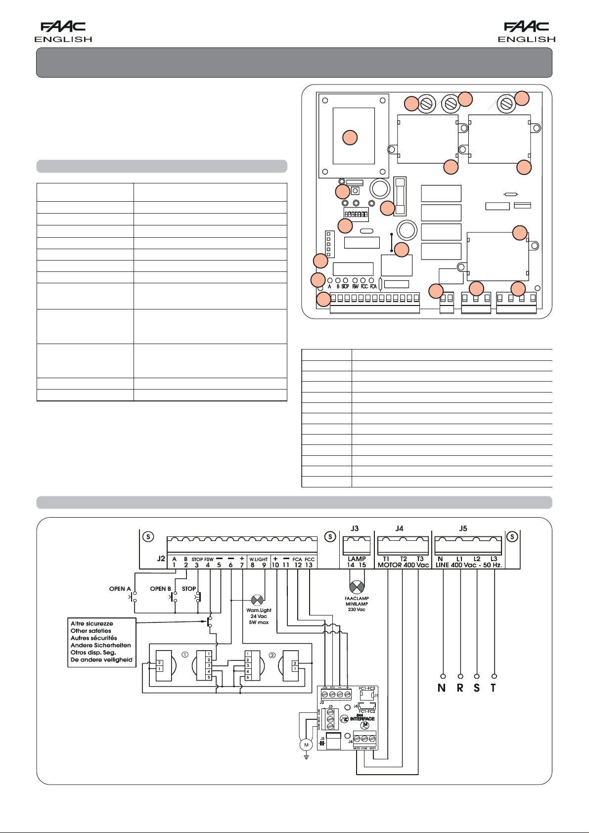
2. ELECTRICAL CONNECTIONS WITH 400V 3ph (N.B.: for connection to 230 V 3ph, see Chapter 8)
Fig. 1
8
Page 3

3. DESCRIPTION
3.1. J1 PLUG
The J1 plug is used for rapid connection of cards MINIDEC,
DECODER, RP RECEIVERS (Fig. 3, 4, 5)
Install by fitting the accessory cards so that their components
side faces the inside of the 844 T electronic appliance.
Insert and remove the cards after cutting power.
Fig. 3 Fig. 4 Fig. 5
PLUS
9 = Warning light output (24 Vac)
The maximum load of the warning light is 5 W.
For instructions on operation of the warning light, consult
microswitch programming.
!!
! If you cut out jumper LK1, you obtain a voltage free
!!
contact between terminals 8 and 9 (see Fig. 6).
10 = 24 Vdc (+) power supply for inductive limit switch
11 = Limit switch common contact
12 = Opening limit switch (N.C.)
13 = Closing limit switch (N.C.)
3.3. TERMINAL BOARD J3 (high voltage)
Terminal board for connecting flashlight (max 60W).
844MPS
844 T
MINIDEC
SL/DS
844MPS
844 T
DECODER
SL/SLP/DS
844MPS
844 T
3.2. TERMINAL BOARD J2 (low voltage)
1 = OPEN A (N.O.) – T otal opening
This is any pulse generator with N.O. contact which, when
activated, produces a gate opening movement. In A, E
and S logics, it commands both opening and closing.
To install several Open A devices, connect N.O. contacts
in parallel.
2 = OPEN B (N.O.) – Opening for pedestrians / Closing
This is any pulse generator with N.O. contact which, when
activated in logics A, E and S, produces a gate opening
movement for pedestrians. In B and C logics, it commands
a closing movement.
To install several Open B devices, connect N.O. contacts
in parallel.
3 = STOP command (N.C.)
This is any device (e.g. a push-button) which, by opening
a contact, stops gate movement.
To install several stop devices, connect the N.C. contacts
in series.
!If Stop devices are not connected, link the input to the
common contact (terminal 5) via a jumper.
4 = FSW closing safety devices contact (N.C.)
Safety devices are all devices (photocells, sensitive edges,
magnetic coils) with N.C. contact, which, if there is an
obstacle in the area they protect, operate to interrupt
gate movement. The purpose of the closing safety devices
is to protect the gate movement area during closing.
If the safety devices are tripped during closure, gate
movement is reversed, whereas they have no effect during
opening. If used when the gate is open or pausing, closing
safety devices prevent its closing.
To install several safety devices, connect the N.C. contacts
in series.
!!
! If closing safety devices are not connected, link this
!!
input to the common contact (terminal 5) via a jumper.
5 = Common contact for commands
6 = Negative of accessories power supply
7 = 24 Vdc (+) power supply for accessories
Max load of accessories is 500 mA.
To calculate absorption values, refer to the instructions
for individual accessories.
3.4. TERMINAL BOARD J4 (high voltage)
Terminal board for connection of motor.
3.5. TERMINAL BOARD J5 (high voltage)
Terminal board for supplying power of 400V 3ph + Neutral - 50 Hz
(see Fig. 1) or 230V 3ph - 50 Hz (see Fig. 8).
Connect the yellow-green earth cable as shown in Fig. 7.
!!
INTERRUPTED LK1
!
COMPLETE LK1
7
6
8
24V~ 5W max
9
Fig. 6
!!
(Free contact)
8
2A max
9
Fig. 7
9
Page 4

3.6. SIGNALLING LEDs
6 LEDs are fitted on the card, indicating status of terminal board
inputs:
LED
LIGHTED
LED
= contact closed
OFF
= contact open
Tab. 2 - STATUS OF LEDS
DELDETHGILFFO
ANEPO
BNEPO
POTS
WSF
CCF
ACF
evitcadnammoC
evitcadnammoC
evitcanidnammoC
gnitarepotonsecivedytefaS
eerfrosnestimilgnisolC
eerfrosnestimilgninepO
evitcanidnammoC
evitcanidnammoC
evitcadnammoC
gnitareposecivedytefaS
degagnerosnestimilgnisolC
degagnerosnestimilgninepO
NB.: The status of the LEDs while the gate is closed at rest are
shown in bold.
4.1. FUNCTION LOGICS
The following are available:
A1/A2 = “Automatic” S1/S2 = “Safety”
E1/E2/B = “Semi-automatic” C = “Dead man”
Operation of automation in the different logics is indicated in
Tables 3 - 4 - 5 - 6 - 7 - 8 - 9 - 10.
4.2. PAUSE TIME
Pause time is waiting time in open position before re-closing
when an automatic logic was selected.
Pause times include pre-flashing if any
4. PROGRAMMING
To program operation of automation, use the microswitches as
shown below.
Logic SW1 SW2 SW3
E1 ON ON ON
B OFF ON ON
S2 ON OFF ON
E2 OFF OFF ON
A1 ON ON OFF
C OFF ON OFF
S1 ON OFF OFF
A2 OFF OFF OFF
ON
1 2 3 4 5 6 7
OFF
Operation of warning light
Closed Opening/Open Closing
SW6
ON
Light
Off
OFF
(1) Pause times include pre-flashing if any
(2) Pre-flashing begins 5” before every movement.
Gate status
Steady light
Light
Flashing
! You must press the RESET push-button after every program-
ming job.
Pause time (sec) (1)
Logic
A1-A2-S2 S1 SW4 SW5
515ONON
10 30 OFF ON
30 60 ON OFF
120 180 OFF OFF
Pre-flashing (2)
Yes ON
No OFF
SW7
4.3. OPERATION OF WARNING LIGHT
Used to change the appearance of the warning light at closing
by making it flash.
4.4. PRE-FLASHING
Flashlight pre-flashing time of 5 sec before any movement can
be selected. This warns anyone near the gate that it is about to
move.
5. FAULT CONDITIONS
The following conditions cause certain effects to normal operation of automation:
햲 microprocessor error
햳 safety electronic timing tripped (operation is interrupted if
continuous work time exceeds 255 sec. ).
햴 limit sensors disconnected (or both engaged)
• Conditions 햲 and 햳 cause automation to stop and nothing
more.
• Condition 햴 causes an alarm situation disabling any activity:
• Normal operation can be restored only after eliminating the
alarm cause and pressing the RESET push-button (or turning
off power supply momentarily).
• To have this condition signalled, the warning light must be
connected: the alarm is signalled by very rapidly flashing light
(0.25 sec).
10
Page 5

6. LIMIT SENSORS CONNECTION CHECK
1) Manually take the gate toward opening position, and
check if, with the leaf open, the FCC LED is lighted and the
FCA LED is off.
2) Manually take the gate toward closing position, and check
if, with the leaf closed, the FCA LED is lighted and the FCC
LED is off.
2) If the LEDs are inverted, changeover the cables conected to
trminals 12 and 13.
7. ROTATION DIRECTION CHECK
1) Release the operator, take it manually to mid-travel and relock it.
2) Power up the system and then press the RESET push-button.
3) Give an Open command to the operator, check if the gate
moves in opening direction and then press the RESET pushbutton to stop the leaf moving.
4) If rotation direction is incorrect, change over wiring of cables
T1 and T3 of the electric motor.
8. ELECTRICAL CONNECTIONS WITH 230V 3ph
To connect the 844 T appliance to a 3-phase 230 V mains, observe the diagram in Fig. 8.
N.B.: The electric motor of the gearmotor must be 230V 3-phase.
Fig. 8
11
Page 6

Tab. 3 - LOGIC A1 (AUTOMATIC)
"1A"cigoLSESLUP
SUTATSSETAG)1(BNEPO-ANEPOPOTSSECIVEDYTEFAS
DESOLC
ESUAPNONEPO
GNISOLC
GNINEPO
DEPPOTS
retfasesolcdnasnepO
)2(emitesuap
)3("5retfasesolc-eRtnuocehtspotStnemegagnesidlitnuesuapsezeerF
noitomsesreveRspotSnoitomsesreveR
tceffeoNspotStceffeoN
)2(sesolc-eRtceffeoNtceffeoN
tceffeoNtceffeoN
Tab. 7 - LOGIC E1 (SEMI-AUTOMATIC)
"1E"cigoLSESLUP
SUTATSSETAG)1(BNEPO-ANEPOPOTSSECIVEDYTEFAS
DESOLC
NEPO
GNISOLC
GNINEPO
DEPPOTS
)2(snepOtceffeoNtceffeoN
)2(sesolc-eRtceffeoNtceffeoN
noitomsesreveRspotSnoitomsesreveR
spotSspotStceffeoN
secivedytefasnehw(sesolc-er
)2()snepo-erti,degagne
tceffeoNtceffeoN
Tab. 4 - LOGIC A2 (AUTOMATIC PLUS)
"2A"cigoLSESLUP
SUTATSSETAG)1(BNEPO-ANEPOPOTSSECIVEDYTEFAS
DESOLC
ESUAPNONEPO
GNISOLC
GNINEPO
DEPPOTS
retfasesolcdnasnepO
)2(emitesuap
)3("5retfasesolc-eRtnuocehtspotS
noitomsesreveRspotS
tceffeoNspotStceffeoN
)2(sesolc-eRtceffeoNtceffeoN
Tab. 5 - LOGIC S1 (SAFETY)
"1S"cigoLSESLUP
SUTATSSETAG)1(BNEPO-ANEPOPOTSSECIVEDYTEFAS
DESOLC
ESUAPNONEPO
GNISOLC
GNINEPO
DEPPOTS
retfasesolcdnasnepO
)2(emitesuap
)3-2(yletaidemmisesolCtnuocehtspotS
noitomsesreveRspotSnoitomsesreveR
noitomsesreveRspotStceffeoN
)2(sesolc-eRtceffeoNtceffeoN
tceffeoNtceffeoN
tceffeoNtceffeoN
Tab. 8 - LOGIC E2 (SEMI-AUTOMATIC PLUS)
"2E"cigoLSESLUP
SUTATSSETAG)1(BNEPO-ANEPOPOTSSECIVEDYTEFAS
DESOLC
,degagnesidnehW
"5retfasesolc-er
sesreverdnaspotS
)2(tnemegagnesidta
NEPO
GNISOLC
GNINEPO
DEPPOTS
)2(snepOtceffeoNtceffeoN
)2(sesolc-eRtceffeoNtceffeoN
noitomsesreveRspotS
spotSspotStceffeoN
ytefasnehw(sesolc-eR
)2(
)snepo-erti,degagnesecived
tceffeoNtceffeoN
sesreverdnaspotS
)2(tnemegagnesidta
Tab. 9 - LOGIC B (SEMI-AUTOMATIC)
"B"cigoLSESLUP
SUTATSSETAGANEPO)4(BNEPOPOTSSECIVEDYTEFAS
DESOLC
,degagnesidnehw
”5retfasesolc-er
NEPO
GNISOLC
GNINEPO
DEPPOTS
)2(snepOtceffeoNtceffeoNtceffeoN
tceffeoN)2(sesolCtceffeoNgnisolcstneverp
tceffeoNtceffeoNtnemevomspotStnemevomspotS
tceffeoNtceffeoNtnemevomspotStceffeoN
)2(gnineposetelpmoC)2(gnisolcsetelpmoCtceffeoNgnisolcstneverp
Tab. 6 - LOGIC S2 (SAFETY PLUS)
"2S"cigoLSESLUP
SUTATSSETAG)1(BNEPO-ANEPOPOTSSECIVEDYTEFAS
DESOLC
ESUAPNONEPO
GNISOLC
GNINEPO
DEPPOTS
retfasesolcdnasnepO
)2(emitesuap
)3-2(yletaidemmisesolCtnuocehtspotStnemegagnesidlitnuesuapsezeerF
noitomsesreveRspotS
noitomsesreveRspotStceffeoN
)2(sesolc-eRtceffeoNtceffeoN
tceffeoNtceffeoN
tasesreverdnaspotS
)2(tnemegagnesid
Tab. 10 - LOGIC C (DEAD MAN)
"C"cigoL
SUTATSSETAG)5(ANEPO)5dna4(BNEPOPOTSSECIVEDYTEFAS
DESOLC
NEPO
GNISOLC
GNINEPO
DEPPOTS
snepOtceffeoNtceffeoNtceffeoN
tceffeoNsesolCtceffeoNgnisolcstneverp
tceffeoNtnemevomspotStnemevomspotS
gnineposetelpmoC
(1) OPEN B input commands partial opening.
(2) With pre-flashing selected, movement begins after 5 sec.
(3) If the pulse is sent during pre-flashing, counting is restarted.
(4) OPEN B input commands closing.
(5) Push-button must be kept pressed to activate gate movement. When the push-button is released, the gate stops.
12
NWODDLEHSLORTNOC
YLSUOUNITNOC
tceffeoNtnemevomspotStceffeoN
setelpmoC
gnisolc
SESLUP
tceffeoNgnisolcstneverp
 Loading...