

Page 1
ENGLISHENGLISH
5. START-UP
5.1. CONNECTION TO ELECTRONIC CONTROL UNIT
Warning: Always turn off the electricity supply before
carrying out any work on the electronic control unit
(connections, programming, maintenance).
Observe points 10, 11, 12, 13 and 14 in the GENERAL SAFETY
INSTRUCTIONS.
Since the system requires two different power supplies (230
and 400 Vac), install two differential magneto-thermal
circuit breakers with adequate trip threshold up-line of the
system.
Connect the earth cable to the connection on the base of
the operator. See fig. 15.
The gearmotor is provided with a safety device (Fig.1 Ref.
7) operated by the relase system.
While activated the safety device keeps the gearmotor
from making any movement.
As shown in Fig. 3, prepare the conduits and make the
electrical connections from the 844MPST electronic control
unit to the chosen accessories.
Always route the power supply cables separately from the
control and safety cables (keyswitch, receiver, photocells,
etc.). Use separate conduits to avoid any interference.
Table 2 Technical specifications 844MPST
Power supply 230 V (+6% - 10%) 50 Hz
Absorbed power 10W
Max. motor load 800W
Max. electric lock load 0.5A
Temperature range -20 °C +55 °C
Fuses 3 (see fig. 5.1.1)
Operation logics Automatic / Semiautomatic /
Safety / Semiautomatic B /
Deadman C
Pause time Adjustable by dip-switches
Terminal block inputs Open / Partial opening-Close
Stop / Closing safeties /
Power supply
Terminal block outputs Flashing light - motors -
24 Vdc accessories power supply -
24 Vdc warning lamp power supply -
Quick connector Decoder cards / RP-SL-DS
Programmable functions Operating logics / Pause times /
Warning lamp operation
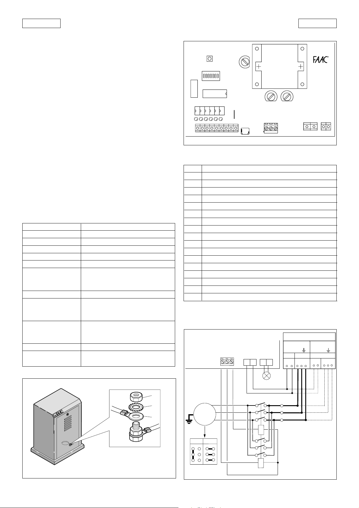
5.1.1. LAYOUT AND ELECTRICAL CONNECTIONS
F2
LK1
ACCESS.
J3
TRASF.
F3
J5
F1
J8
LN
P1
RESET
DS1
J1
DECODER
DECODER-SL
DL6
DL1 DL2 DL3 DL4 DL5
CLOSE OPEN STOP FSW FCC FCA
J2
123456789
Table 3 Control unit components 844MPST
LD1 OPEN LED
LD2 STOP LED
LD3 SAFETY LED
LD4 CLOSURE LIMIT SWITCH LED
LD5 OPENING LIMIT SWITCH LED
LD6 LED OPEN PARTIAL / CLOSE
P1 RESET BUTTON
J1 DECODER CONNECTOR
J2 LOW VOLTAGE TERMINAL BLOCK
J3 LIMIT SWITCH CONNECTOR
J5 CONTACTOR CONNECTION TERMINAL BLOCK
J7 FAAC LAMP CONNECTION TERMINAL BLOCK
J8 POWER SUPPLY
F1 CONTACTOR FUSE (F5 A)
F2 ACCESSORIES FUSE (T 1.6 A)
F3 TRANSFORMER FUSE (T250 mA)
LK1 WARNING LAMP FREE CONTACT
DS1 PROGRAMMING DIPSWITCH
5.1. 2 HIGH VOLTAGE ELECTRICAL CONNECTIONS
POWER SUPPLY
844 MPST
J5
AP COM CH
J8
J7
400V
3Ph+N+
230V
NR
380V
R
T
S
844MPS
J7
Fig. 16
230V
3Ph+
230V
R
SRS
T
1
2
3
Fig. 15
15
M 3Ph
400 230
T1
T2
T3
FLASHING LIGHT
A1
C1
A1
C2
(max 60W)
A2
A2
L1
L2
L3
Fig. 17
Page 2
ENGLISH
ENGLISH
Tab. 4Accessories current draw
TYPE OF ACCESSORY NOMINAL CURRENT DRAW
/ COM
844MPST
WHITE
J3
BROWN
GREEN
MS3
Fig. 18
A/C
OPEN
STOP
FSW
J2
1 23456789
MS1
1
2
3
4
5
+24 Vdc
Warning
light
5W max
Other
Safeties
CLOSING
PHOTOCELLS
W. LIGHT
+24 Vac
1
2
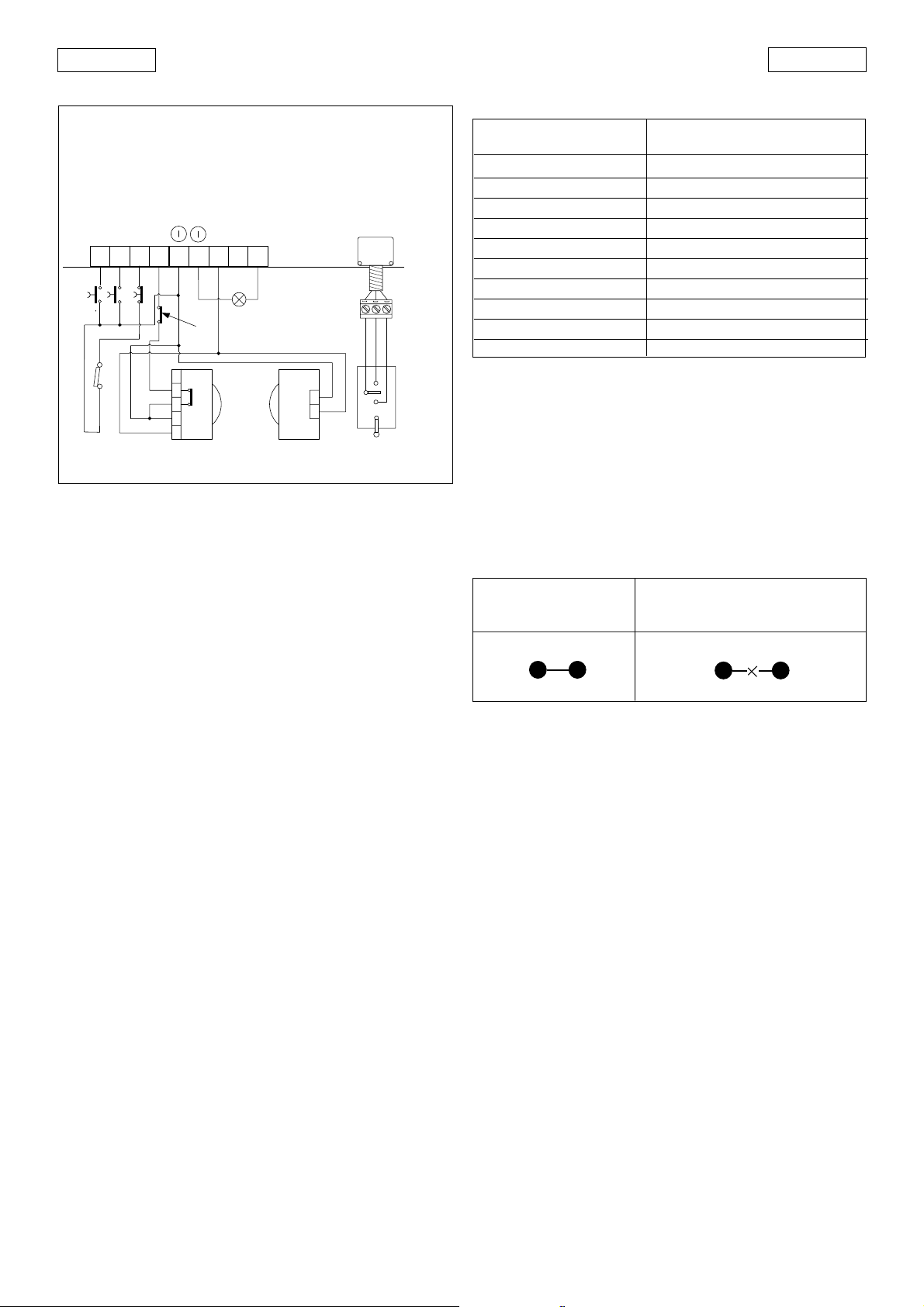
a Low voltage terminal block J2 (Fig. 16) is used to
connect all accessories (see Table 4).
1. A/C Partial opening
This means any control device with a N.O. contact
which causes partial opening of the gate when
activated in E1, E2, A1, A2, S1 or S2 logics. In B and C
logics it causes the gate to close. To install more than
one partial opening control device, connect the N.O.
contacts in parallel.
2. OPEN
This means any control device with a N.O. contact
which causes the gate to open when activated. In
automatic and semiautomatic logics it is active for
both opening and closure. To install more than one
opening control device, connect the N.O. contacts in
parallel.
3. STOP
This means a control device with a N.C. contact which
causes the gate status (opening-pause-closure) to be
interrupted until the next impulse is sent. To install more
than one stop device, connect the N.C. contacts in
series to MS1 and MS2.
4. FSW SAFETIES
This means all devices (photocells, safety edges,
magnetic loops) with a N.C. contact which stop the
movement of the gate when an obstacle is present in
the area protected by the safety devices. To install
more than one safety device, connect the N.C.
contacts in series.
N.B.: if safety devices are not connected, jumper
terminals 4 and 5 on the electronic control unit.
5.
Controls common and accessories power supply
negative
6. 24 Vac output for warning lamp power supply
7. +24 Vdc accessories power supply positive
Warning: the maximum load of the accessories is 500mA.
To calculate power consumption refer to the corresponding
table.
PLUS 40SL 30mA
PLUS E 20mA
MINIDEC SL / DS 6mA
DECODER SL/DS 20mA / 55mA
RP ESL / EDS 12mA / 6mA
DIGICARD 15mA
METALDIGIKEY 15mA
FOTOSWITCH 90mA
DETECTOR F4 / PS6 50mA
PHOTOBEAM 50mA
W.LIGHT (terminals 6 - 8 - 9)
These are the 24 Vdc terminals to which the warning lamp
must be connected. With jumper LK1 intact it is possible to
power a 24V / 5W max. warning lamp between terminals
6 and 9. In case a potential free contact is needed
between the terminal strips 8 and 9, the link LK1must be
cut. (see Table 5).
WARNING: If the jumper LK1 is broken, the 24 Vac
accessories power supply (terminals 6 and 8) is no longer
available.
Table 5: Warning lamp connection
LK1 INTACT LK1 BROKEN
(FREE CONTACT)
b Connector J3 limit switch unit connection
c Terminal block J5 contactor connection
The motor control contactors must be connected to
these terminals.
d Terminal block J6 (fig. 16)
L: 230V power supply (live)
N: 230V power supply (neutral)
e Terminal block J7 (fig. 16)
Flashing light output (230V)
6. BEHAVIOUR OF SAFETY DEVICES
The safety devices operate during closure only. In "A1", "E1"
and "S1" logics, interrupting the safety device contacts
causes the gate to stop closing and start opening
immediately. In "A2", "E2" and "S2" logics, interrupting the
safety device contacts causes the gate to stop closing,
then to start opening again when the safety devices are
released.
In "B" and "C" logics, interrupting the safety device contacts
causes the gate to stop closing.
7. DIPSWITCH SETTINGS
To program automation operation, set the dipswitches as
shown in the diagram below.
16
Page 3

Logic SW1 SW2 SW3
E1 ON ON ON
B OFF ON ON
S2 ON OFF ON
E2 OFF OFF ON
A1 ON ON OFF
C OFF ON OFF
S1 ON OFF OFF
A2 OFF OFF OFF
1234567
Warning lamp operation
Closed Opening/Open Closing
SW6
ON
OFF
(1) Pause times include pre-flashing.
(2) Pre-flashing commences 5 seconds before the start of each
movement.
Off
Gate status
Steady light
Pause time (sec) (1)
Logic
A1 A2 S2 S1 SW4 SW5
515ONON
10 30 OFF ON
30 60 O N OFF
120 180 OFF OFF
Pre-flashing (2) SW7
Yes ON
No OFF
Steady light
Flashing
N.B.: PRESS THE RESET BUTTON AFTER ALL PROGRAMMING
OPERATIONS.
8. OPERATION IN VARIOUS LOGICS
The following 8 logics are available:
E1/E2/B: "Semiautomatic" A1/A2: "Automatic"
S1/S2: "Safety" C: "Deadman"
Operation of the various logics is shown in tables 6-7-8-9-10-1112-13.
TABLE 6 LOGIC E1 (SEMIAUTOMATIC)
LOGIC E1
GATE STATUS
CLOSED
OPEN
CLOSING
OPENING
STOPPED
OPEN - A/C (1) -
opens (2)
recloses (2
inverts motion
stops
recloses (reopens when safety
devices are engaged) (2)
IMPULSES
STOP
no effect
no effect
stops
stops
no effect
SAFETY
no effect
no effect
inverts motion
no effect
no effect
TABLE 7 LOGIC E2 (SEMIAUTOMATIC)
TABLE 8 LOGIC A1 (AUTOMATIC)
LOGIC A1
GATE STATUS
CLOSED
OPEN
CLOSING
OPENING
STOPPED
OPEN - A/C (1) -
opens and recloses after
pause time (2)
recloses after 5 s (3)
inverts motion
no effect
recloses (2)
TABLE 9 LOGIC A2 (AUTOMATIC)
LOGIC A2
GATE STATUS
CLOSED
OPEN
CLOSING
OPENING
STOPPED
OPEN - A/C (1) -
opens and recloses after
pause time (2)
recloses after 5 s
(3)
inverts motion
no effect
recloses (2)
TABLE 10 LOGIC S1 (SAFETY)
LOGIC S1
GATE STATUS
CLOSED
OPEN
CLOSING
OPENING
STOPPED
OPEN - A/C (1) -
opens and recloses after
pause time (2)
recloses immediately
(2 and 3)
inverts motion
inverts motion
recloses (2)
TABLE 11 LOGIC S2 (SAFETY)
LOGIC S2
GATE STATUS
CLOSED
OPEN
CLOSING
OPENING
STOPPED
OPEN - A/C (1) -
opens and recloses after
pause time (2)
recloses immediately
(2 and 3)
inverts motion
inverts motion
recloses (2)
TABLE 12 LOGIC B (SEMIAUTOMATIC)
LOGIC B IMPULSES
GATE STATUS
CLOSED
OPEN
CLOSING
OPENING
STOPPED
OPEN
opens (2)
no effect
no effect
no effect
completes
opening (2)
A/C (5)
no effect
closes (2)
no effect
no effect
completes
closing (2)
TABLE 13 LOGIC C (DEADMAN)
LOGIC C IMPULSES
GATE STATUS
CLOSED
OPEN
CLOSING
OPENING
STOPPED
OPEN (4)
opens
no effect
no effect
completes opening
A/C (4 and 5)
no effect
closes
no effect
completes closing
IMPULSES
STOP
no effect
stops counting
stops
stops
no effect
IMPULSES
STOP
no effect
stops counting
stops
stops
no effect
IMPULSES
STOP
no effect
stops counting
stops
stops
no effect
IMPULSES
STOP
no effect
stops counting
stops
stops
no effect
SAFETY (until
disengagement)
no effect
inhibits closing
stops
no effect
inhibits closing
SAFETY (until
disengagement)
no effect
inhibits closing
stops
no effect
inhibits closing
ENGLISHENGLISH
SAFETY
no effect
freezes pause until
disengagement
no effect
no effect
no effect
SAFETY
no effect
recloses after 5 s when
disengaged
inverts motion
no effect
no effect
SAFETY
no effect
recloses after 5 s when
disengaged
inverts motion
no effect
no effect
SAFETY
no effect
freezes pause until
disengagement
stops and inverts motion
when disengaged (2)
no effect
no effect
STOP
no effect
no effect
stops movement
stops movement
no effect
STOP
no effect
no effect
stops
stops
stops
no effect
LOGIC E2
GATE STATUS
CLOSED
OPEN
CLOSING
OPENING
STOPPED
IMPULSES
OPEN -A/C(1)-
opens (2)
recloses (2)
inverts motion
stops
recloses (reopens when safety
devices are engaged) (2)
STOP
no effect
stops counting
stops
stops
no effect
SAFETY
no effect
no effect
freezes pause until
disengagement
no effect
no effect
17
(1) The A/C input enables partial opening.
(2) With pre-flashing selected movement starts after 5
seconds.
(3) If the impulse is sent after pre-flashing the timer recounts.
(4) For operation in C logic keep the pushbutton depressed.
Movement stops upon release.
(5) The A/C input controls closure.
 Loading...