

Page 1

T HE 455 D CONTROL PANEL:
S UPPLEMENTAL INSTALLATION
NSTRUCTIONS
I
CONTENTS
General Description 2
Installing the 455 D Control Panel 2
Connect the Main Power Supply 2
Connect the Operator(s) to the Control Panel 3
Check the Motor’s Direction of Rotation 3
November, 2003
455 D Control
Panel Installation
Instructions
Connect Other Devices 4
Set Other Operating Controls 6
Programming 8
Learning of Operating Times 10
Learning of Normal Times 10
Learning Times with Gatecoder 10
Automated System Test 11
Logic Tables of 455 D Control Panel 12
Safety in Gate Design 14
Maintenance 14
Limited Warranty 16
FAAC International, Inc.
303 Lexington Avenue
Cheyenne, WY 82007
www.faacusa.com
Note: These instructions supplement the
installation manual for your operator. Be
sure to review all safety information in the
installation manual for your operator.
Page 2

Page 2
November, 2003
455 D Control Panel Installation Instructions
THE 455 D CONTROL PANEL
GENERAL DESCRIPTION
The FAAC 455 D control panel is used to operate the
following models.
Swing gate operators:
400 412
402 750
422 760
Barrier gate operators:
610/615
The 455 D programming controls the following:
Operating logic: A, S, E, EP, B, and C logics
available.
Reversing device behavior: Choose whether a
triggered reversing device during closing
immediately reverses gate movement or stops the
gate and reverses gate movement when no longer
triggered.
Torque or Pressure: Force adjustment for the 412
operator. Adjustable from 0 to 50.
Caution: For all hydraulic operators, the torque
must be programmed to the maximum (50) setting.
Pause time between opening and closing:
adjustable from 0 to 240 seconds.
Opening/Closing time: adjustable
from 0 to 120 seconds.
Leaf delay on closing: adjustable from 0 to 4.1
minutes.
The 455 D control panel should be installed in an
enclosure that is conveniently located as close as
possible to the gate operator. All electrical connections
from the control panel to the operator must be made in
a weatherproof junction box.
The 455 D control panel requires a single-phase power
supply voltage (115 VAC [±10%] or 230 VAC [+6 or 10%], 50–60 Hz). The power supply should be protected
by a 15 amp dedicated circuit breaker (not provided).
The installer is responsible for grounding the
operator system, for providing the main power
breaker switch, and for making sure that the entire
gate system meets all applicable electrical codes.
The installer should refer to the installation manual
for a given operator for more information.
N
OTE: An installation is U.L. compliant only
when you install the FAAC operators according
to the UL325 standards.
NSTALLING THE 455 D CONTROL
I
ANEL
P
Locate the control panel in the most convenient position
possible, considering the movement of the gate.
Installing the control panel consists of the following
general steps:
• Connecting the main power to the control
panel
• Connecting the activating device
• Connecting the operator to the control panel
• Checking the direction of the motor's rotation
• Connecting other devices to the control panel
• Set operating modes
CONNECT THE MAIN POWER SUPPLY
WARNING! Turn the main power off before you
make any electrical connections or before
programming.
Wire the main power supply to control panel terminals
in block J3 (see Figures 1 and 2). The installer is
responsible for insuring that a separate, grounded
circuit protected by a circuit breaker is between the
control panel and the main power supply. All wiring
should conform to applicable electrical codes, and all
wiring and fittings should be weatherproof and/or
suitable for burial.
Connect the ground to the grounding terminal in block
J3 and connect the power wires to the terminals labeled
N (neutral) and L (line).
N
OTE: For a 230V system, a neutral is not
needed. Connect one 115V line to the L (Line)
and a second 115V line to the N (Neutral).
Page 3
November, 2003
455 D Control Panel Installation Instructions
Page 3
CONNECT THE OPERATOR(S) TO THE
ONTROL PANEL
C
WARNING!
make any electrical connections or before
programming.
CAUTION: The operators are grounded only by
the grounded circuit the installer provides.
USING A JUNCTION BOX
If an operator is more than 2 ft away from the control
panel, you must use a junction box for connection. Use
a U. L. Listed cord grip where the operator cord enters
the junction box.
Note: If you have a one-leaf gate design, the
operator must be connected to Motor 1 (terminals
1,2, & 3)
To wire up motor 1, connect the white wire to terminal
1(on the J4 terminal strip), the black wire to 2, and the
red wire to 3. Wire each leg of the capacitor (supplied)
to terminals 2 & 3.
Note: If you want to delay the closing of one gate
leaf in a two-leaf gate design, be sure to connect
its operator to Motor 1.
Turn the main power off before you
In order to wire motor 2 in a bi-parting system, connect
the white wire to terminal 4 (on the J4 terminal strip),
the black wire to 5, the red wire to 6. Wire each leg of
the capacitor (supplied) to terminals 5 & 6.
CHECK THE MOTOR’S DIRECTION OF
OTATION
R
After you have connected the main power supply, and
the operator(s) to the control panel, you need to check
the direction of rotation for each operator motor in your
gate design.
Note: To check a motor’s direction of rotation,
you must have three closed circuits on terminal
block J1. Install one circuit between terminals 11
and 16, another circuit between terminals 12 and
19, and another circuit between terminals 13 and
19.
J3
K
1-455D115 = 115V
1-455D = 230V
M
N L
MAIN
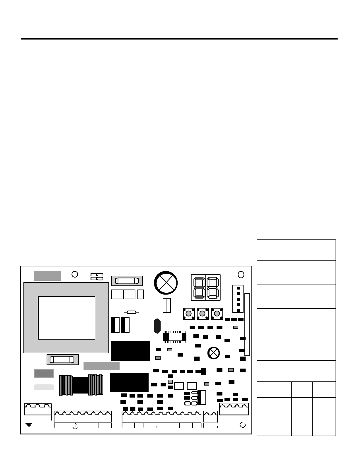
Figure 1. The 455 D Control Panel
F1
1 2 3 4 5 6 7 8
MOTOR 1
MOTOR 2
M
LAMPCOMOP CL
CLCOMOP
F2
J4J5J1
9 10 11 12 13 14 15 16 17 18 19
NC -B -
A + TX
STOP
V1- 4
61C455D
terminal block for main
J3
power supply
J4 terminal block for
connecting the operator(s)
J2
F-+
J1 terminal block for low-
RADIO
voltage accessories
J2 quick connector port
F Function Push Button
— Programming Push
Button
+ Programming Push
Button
FUSES
Main Power
FCC2
A
F1
F2
ccessories
J6
22 23 24 25
20 21
+OP -CL
+24 VFSW
FSW
W. L.
LOCK
FCA 1
FCA 2
FCC1
220
VAC
5 A 10 A
800
mA
115
VAC
800
mA
Page 4
Page
November, 2003
455 D Control Panel Installation Instructions
NL
115 VA C +/- 10%
or
230 VA C +6/ -10%
50-60 Hz
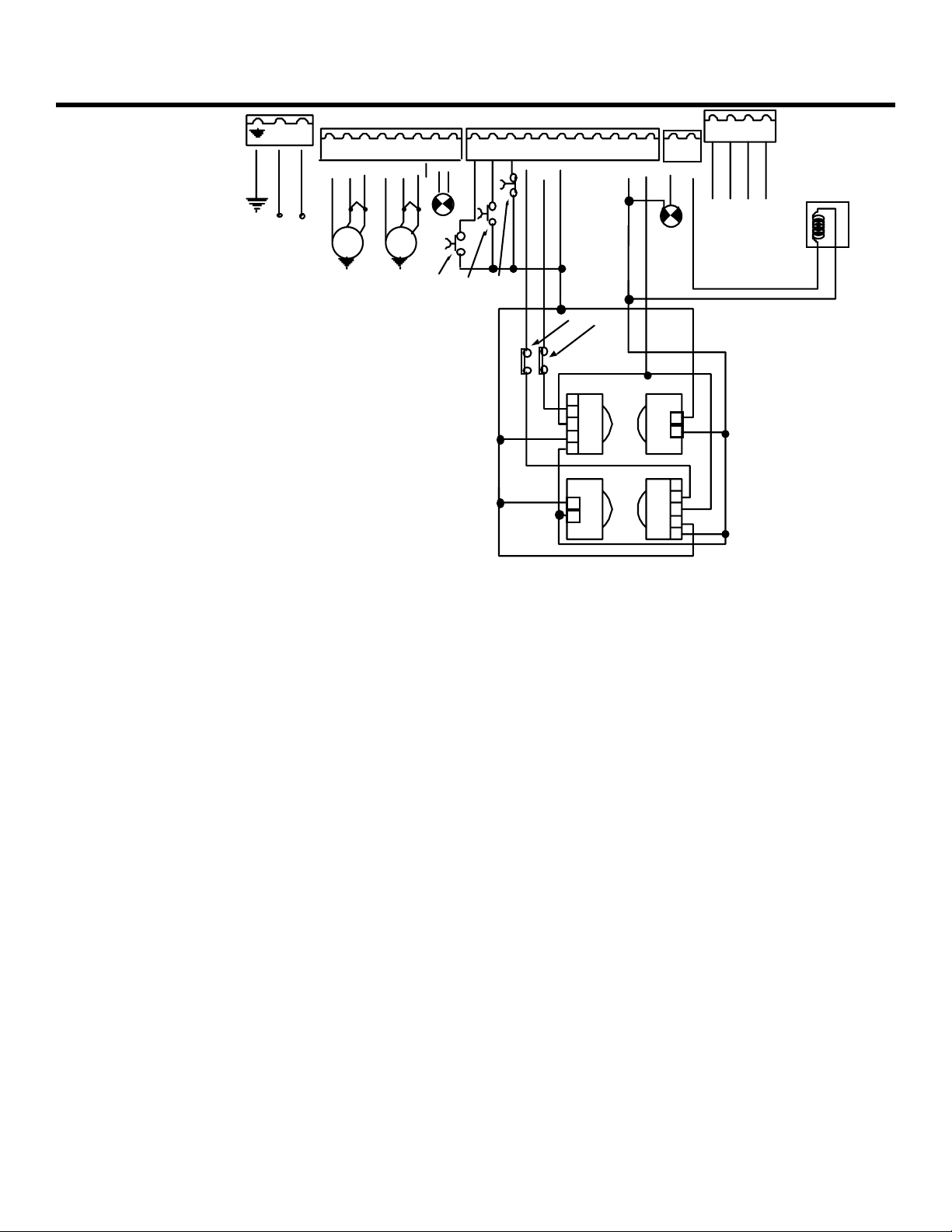
Figure 2.
The terminal strip wiring of the 455
D with photo-beams
NOTE: In order to comply with UL 325, two sets
of FAAC photobeams must be installed. One set
should be 6 in. outside the closed gate(s) and act
as a closing reversing device. Another set should
be 6 in. beyond the swing of the gate(s) and act
as an opening reversing device. The installer is
responsible for determining the appropriate
mounting height.
12345678
OPCOM CL
MOTOR 1
BLUE
MOTOR 2
C1
BLUE
M1
OPCOM CL
M2
LAMP
C2
9 10111213141516171819
STOPOPEN OPEN
(1 of 2)
-
OPCL -
FSW
+
-- +
24V
Other safe ties
1
FSWOP
2
3
4
5
FSWC L
1
2
FSW
20 21
W.LIGHT
24 vdc
3 W
1
2
1
2
3
4
5
LOCK
22 23 24 25
F OR W HEN THE FAAC
GATECODERS AR E USED
ELEC TRIC LO CK
You cannot check the motor’s direction of rotation
without these circuits (jumpers) or the accessories.
When properly prepared for testing, the LEDS FSWOP,
STOP, and FSWCL should be illuminated (see figure 3.5
on page 5).
WARNING! Running the operator—even for testing
purposes—without a connected reversing device is
potentially dangerous. Do not place yourself within
the path of the moving gate during your test.
Disengage the operator(s) with the Manual Release key
(see operator installation manual), and open the gate by
hand about halfway.
Next, engage the operator(s) with the Manual Release
key so that you can check the rotation of the motor(s).
To activate the operator(s) momentarily short across
terminals 9 and 14.
Turn on the main power and send an activating signal to
the operator. The gate leaf (or leaves) should open. If a
gate leaf closes, then you need to turn off the main
power and reverse the connection of the red and black
wires on terminal block J4 for the operator controlling
that leaf. Then you need to recheck the rotation
direction again.
After having completed your test of the motor’s
direction of rotation, replace any test circuits you
installed (between terminals 11 and 16, between 12 and
19, and between 13 and 19) with the proper reversing
and stop devices. The instructions for installing such
accessories follow.
CONNECT OTHER DEVICES
WARNING! Turn the main power off before you
make any electrical connections.
P
OWER SUPPLY FOR ACCESSORIES: You can access a 24 VDC
output for supplying power to accessories through
terminals 17 or 18, (+) and 14 or 15 or 16, (-) on
terminal block J1. In most cases, this source can be
used to power 24 VDC accessories.
N
OTE: The 455 D control panel allows a maximum
accessory load of 800 mA.
R
EVERSING DEVICES: Reversing devices include photocells,
inductive loops, and so forth. All of the reversing
devices should have contacts of the normally closed
(N.C.) type. Where you connect a device depends on
whether you want the device to operate during opening
or during closing.
N
OTE: UL does not recognize the FAAC system
with loop detectors or safety edges. FAAC
photobeams must be used to comply with UL 325.
To wire photobeams, refer to page 4 (see FSWOP for
opening photobeams, and FSWCL for closing
photobeams). Photobeams must be connected as
shown. See also page 7 for the wiring of inductive loops.
If using more than one reversing device, they must be
wired in series.
A
CTIVATING DEVICES AND RADIO RECEIVER: The activating
devices and radio receiver for your gate must have
Page 5
November, 2003
455 D Control Panel Installation Instructions
Page 5
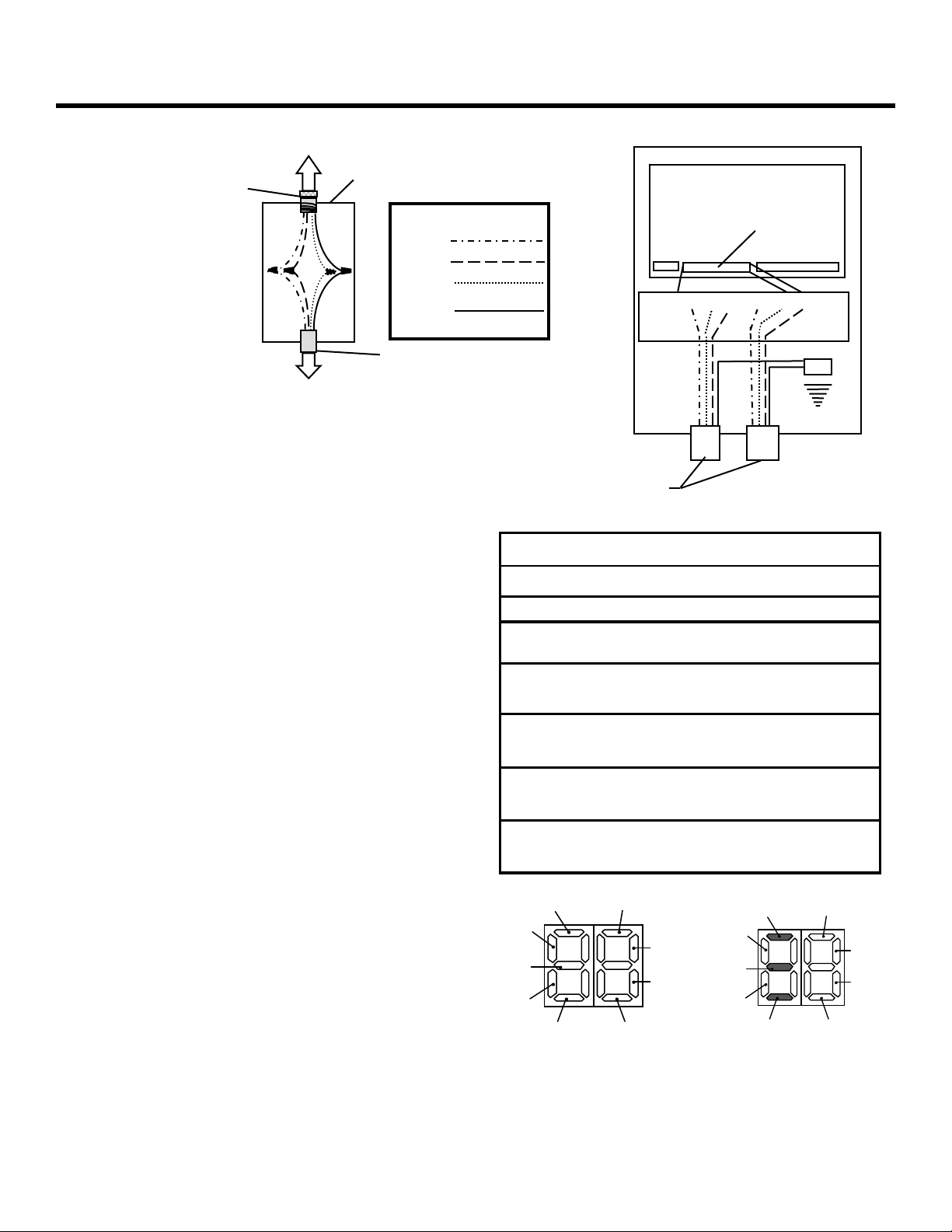
To the U. L. Listed
(a)
U.L. Listed
cord grip
Figure 3.
Wiring detail (a)
inside the junction
box and (b) from the
junction box or
gate operator
Junction box
White
Red
Black
Yellow/
Green
Legend
operator to the high-
voltage terminal strip
on the 455 D control
panel
normally open (N.O.) contacts. Connect such devices to
terminals 9 and 14.
N
OTE: The FAAC radio receiver plugs into the 5
prongs labeled J2 (Quick connect port).
Page 7 shows how to connect a three or four wire
receiver.
D
ECODER CARD: If you are installing the Digicard
magnetic card reader, or the Digikey keyboard, use the
quick-fit connector J2 for the DS decoder card (see
Figure 1).
N
OTE: If your using both a receiver and decoder,
hard wire the decoder and plug in the receiver.
O
PEN/HOLD OPEN DEVICE: To open and hold open the
gate, simply maintain a contact across terminals 9 and
14. (“A” Mode only)
TOP BUTTON: The stop button you install must have
S
normally closed (N.C.) contacts. Multiple
stop buttons must be wired in series. Connect your stop
device between terminals 11 and 16.
N
OTE: The 455 will not operate the motors without
a closed circuit between 11 & 16.
The LED Indicators: The nine light emitting diodes
(LEDs) on the control panel can be used to check for the
proper function of the devices attached to the panel.
The LED lights are on whenever the contacts are closed
across each of the respective terminals.
OP_A and OP_B (Partial Opening) should illuminate only
when an activating signal is sent for 2 and 1 gate leaves,
respectively. STOP should be illuminated except when
the stop button is pressed. FSWOP and FSWCL should be
illuminated except when the reversing devices, for
To the U.L. Listed
control panel
Conduit to U.L. Listed
control panel enclosure
according to N.E.C.
(b)
Cord grip or
conduit from
U.L. Listed gate
operator(s)
LED On Off
OP_A Command Given No Command
OP_B Command Given No Command
Stop No Command Command Given
FSW
Open
FSW
Close
FCA1
FCC1
FCA 2
FCC 2
FSWOP
OP_A
STO P
U.L. Listed Control Panel Enclosure
455 MPS Control Panel
High-voltage
terminal strip
J3 J4
COM OP CL COM OP CL
Op.1 Op.2
Opening reversing
devices clear
Closing reversing
devices clear
Flashes when gate coder is in use.
Operator 1
Flashes when gate coder is in use.
Operator 2
FCA1
FCC1
FSWOP
OP_A
J1
Reversing device
triggered
Reversing device
triggered
STOP
FCC2
OP_B
FSWCL
FCA2
This display shows the
meaning of each LED.
OP_B
FSWCL
This display shows the normal
status of the control panel.
Figure 3.5 The 455 D display.
Ground
FCA1
FCC1
FCC2
FCA2
Page 6

Page 6
November, 2003
455 D Control Panel Installation Instructions
opening and closing, respectively, are triggered. Use
the LEDs and the next table to determine if the
accessory devices you have installed are operating
properly.
Electric Locks: An electric lock can be wired to the 455
D in terminals 18 and 21 (12Vac pulsed provided). If a
reversing stroke is needed to allow the electric lock to
release, this must be done in advanced programming.
See page 7 for the connections for a magnetic locking
device.
W
ARNING LIGHT: Connect a warning light to
terminals 18 and 20 in the group labeled W.LIGHT
in terminal block J1 and J5. The terminals provide
an output voltage of 24 VDC, maximum power 3
Watts. This output voltage will power most 24 VDC
warning lights.
N
OTE: The behavior of the warning light varies
according to the logic you have set.
OGICS A, S, E, EP, AND B: The warning light is on
L
steadily during opening and the pause phase. During
closing, the light flashes.
L
OGIC C: The warning light is on steadily during opening
and flashes during closing.
SET OTHER OPERATING CONTROLS
WARNING! Turn the main power off before you
make any electrical connections.
You need to program the control panel for your gate's
operation. The 455 D Control Panel has on board
programming that controls a wide range of functions.
OPERATING LOGICS
N
OTE: The 455 provides inputs for opening
reversing devices and closing reversing devices.
FAAC strongly recommends the use of
reversing devices, such as photocells or other
non-contact sensors.
• A (automatic): The gate opens on command
and automatically closes after a pause phase. A
second command while opening is ignored; a
second command during the pause phase
interrupts the pause time; a second command
during closing reopens the gate. A maintained
open command will hold the gate open.
• S (security): The security mode is like A logic
except that a second command during opening
immediately closes the gate. A maintained
open command will not hold the gate open.
• E (semi-automatic): This mode requires a
command to open and a command to close. A
second command during opening stops the
gate. A second command during closing
reopens the gate.
• EP (semi-automatic, step by step): This mode
requires a command to open and a command to
close. A second command during opening or
closing causes the gate to stop. A third
command then reverses the previous motion of
the gate.
• B (manned, pulsed): This mode is designed for
guard station use and requires a three-button
switch (pulsed) to open, close, and stop the
gate.
• C (manned and constant): This mode requires
constant pressure switches. One to open and
one to close. No pressure on a switch stops the
gate.
The three programming push buttons allow the
programming of the torque (or pressure), the pause
time between opening and closing, and the leaf delay on
closing.
WARNING! Turn the main power off before you
make any electrical connections.
For all FAAC hydraulic operators using the 455 D
control panel, the force must be set at its maximum
setting of 50 in order to supply the correct voltage to
the operator.
PAUSE TIME: The pause time between opening and
closing can be adjusted from 0 seconds to 4 minutes.
Time is adjusted in one-second increments from 0—59
seconds. When 60 seconds is reached, time is adjusted
in 10 second increments up to 4 minutes. i.e. if display
shows 2.5, it means 2 minutes and 50 seconds.
LEAF DELAY: You may choose to delay one leaf on
closing for overlapping gate leaves. Be sure the operator
on the leaf for delayed closing is connected to Motor 1.
On opening, the leaf connected to Motor 2 is delayed
2.5 sec.
N
OTE: If an opening leaf delay is desired, it must be
enabled in the Advance Programming. However, if
enabled, you cannot adjust this opening delay of
the operator connected to Motor 2.
The closing leaf-delay time is adjustable from 0 to 4
minutes.
N
OTE: If the opening/closing time is set at less
than the leaf delay time, the delayed leaf closes at
the end of the closing time.
Page 7

November, 2003
455 D Control Panel Installation Instructions
Page 7
Free Ex it Loop/ Phone/ F ireb ox
(Hold Open D ev ices)
9
14
FAAC
Rev ersing Photocells
(for opening)
Additional
Reversing Devices
19
17
13
14
17
Magnetic Loc k
-
Lock
+
NO
C
17
14
18
21
12 vac
Relay
N.C.
N.O.
COM
Shadow Loop
1
TX
2
1
19
12
Additional
Reversing Devices
Coil Volt age =
Mot or V olt age
2
3
RX
4
7
8
5
COM
C
NC
N.C.
N.O.
Additional
Reversing Devices
19
17
12
19
17
Reversing Devices
19
12
15
17
FAAC
Rev ersing Photoc ells
(for c losing)
FAAC
Safet y Loop
Additional
Detector
(for c los ing)
3 & 4 Wire R adio R ec eiv ers
1
TX
2
14
1
2
3
RX
9 NO
14
17
If 4 Wire Receiver
C
-
+
4
5
Safet y Series
Wiring
1
TX
2
PHOTO-BEAMS
RX
LOOP
DETECTOR
(FAAC)
FAAC
1
1
2
7
8
19
17
12
14
17
2
3
4
5
1
2
7
8
NO = Normally Open, NC = Normally Closed, C = Common, TX = Transmitter, RX = Receiver
Figure 4. Common Accessories wired to 455 D
Page 8

Page 8
November, 2003
455 D Control Panel Installation Instructions
PROGRAMMING
To program the automated system, the “Programming
Mode” must be accessed.
Programming is split into two parts: BASIC and
ADVANCED.
BASIC PROGRAMMING
To access BASIC PROGRAMMING, press the “F” key.
• If you press it (and hold it down), the display
shows the name of the first function.
• If you release the key, the display shows the value
of the function that can be modified with keys +
and — .
• If you press and hold down the “F” key again (and
hold it down), the display shows the name of the
next function, etc.
• When you reach the last function, press “F” to exit
the program, and the display resumes showing
the status of the inputs.
The table on the right shows the sequence of
functions accessible in BASIC PROGRAMMING.
ADVANCED PROGRAMMING
To access ADVANCED PROGRAMMING, press the “F”
key and, as you hold it down, press the “+” key:
• If you release the “+”, the display indicates the
name of the first function.
• If you release the “F” key, too, the display shows
the value of the function that can be modified
with keys “+” and “—”.
• If you press the “F” key (and hold it down), the
display shows the name of the next function, and
if you release it, the value that can be modified
with keys “+” and “—”.
• When you reach the last function, press the “F”
key to exit the program, and the display resumes
showing the status of the inputs.
The table on page 9 shows the sequence of functions
accessible in ADVANCED PROGRAMMING:
BASIC PROGRAMMING
F
Display Function Default
OPERATING LOGICS
A = Automatic (Timer to Close)
E = Semi Automatic
S = Security
EP = (Semi-Automatic) Step by Step
B = Manned, Pulsed
C = Manned, constant
PAUSE TIME
This is the time between open and
closing and is adjustable from 0 to
4 min. This is only true in “A”
Mode. (see pause time description)
FORCE/TORQUE MOTOR 1
This adjusts the force / torque that
motor 1 is applying to the gate
leaf. Setting is 0 to 50.
FORCE/TORQUE MOTOR 2
This adjusts the force / torque that
motor 2 is applying to the gate
leaf. Setting is 0 to 50.
CLOSING LEAF DELAY
Delays the closing of operator
wired into motor one outputs.
Adjustable from 0 to 4 minutes
(Same as pause time)
MOTOR RUN TIME
This enables where you choose
from “simple” learning or
“complete” learning of the motor
run time. See page 10 & 11 for
complete details.
Simple Learning
~
Complete Learning
> 3 s.
*
*
+
1 s.
+
PROGRAM BUTTONS
+ -
LEFT MIDDLE RIGHT
F
* With Hydraulic operators the Force/Torque must be set to
the maximum setting of 50.
EXIT PROGRAMMING
Exit from programming and return
to display of inputs status.
Page 9

November, 2003
455 D Control Panel Installation Instructions
Page 9
ADVANCED PROGRAMMING
+
F
+
Display Function Default
MAXIMUM TORQUE AT INITIAL THRUST:
The motors operate at maximum
torque (ignoring the torque setting)
at start of movement. Useful for
heavy leaves.
4 = Enable
No = Disabled
LAST STROKE AT CLOSING:
The motors are activated at full
speed for 1s to facilitate locking of
the electric lock.
4 = Enable
No = Disabled
REVERSING STROKE:
Before opening, while the gate is
closed, the motors thrust to close
for 2 s thus facilitating release of the
electric lock.
4 = Enable
No = Disabled
LEAF 2 OPENING DELAY (2S):
Enables delayed start (at opening) of
leaf 2, avoiding interference between
leaves.
4 = Enable
No = Disabled
FAIL SAFE:
If this function is activated, it
enables a function test of the
photocells before any gate
movement. If the test fails
(photocells not serviceable), the gate
does not start the movement.
4 = Enable
No = Disabled
PRE FLASHING (5S):
Activates the flashing lamp for 5s
before start of movement.
4 = Enable
No = Disabled
ELECTRIC LOCK ON LEAF 2:
For using the electric lock on leaf 2
instead of on leaf 1.
4 = Enable
No = Disabled
Display
Function Default
INDICATOR-LICHT:
If 0 is selected, the output functions
as a standard indicator-light (lighted
at opening and pause, flashing at
closing, and off when gate closed).
Different figures correspond to timed
activation of the output, which can be
used (via a relay) to power a courtesy
lamp. Time can be adjusted from 0
to 59s in 1s increments, and from 1.0
to 4.1 min. in 10s steps.
0 = Standard Indicator-Light
From 1 to 4.1 = Timed Output
CLOSING PHOTOCELLS REVERSE AT
RELEASE:
Enable this function if you want the
closing photocells to stop the gate
movement and reverse it after the
beam is cleared. Default setting is
immediate reverse.
4 = Enable
No = Disabled
A.D.M.A.P. FUNCTION:
If this function is enabled, the safety
devices operate in compliance with
French standard NFP 25/362.
4 = Enable
No = Disabled
ASSISTANCE REQUEST (COMBINED WITH
NEXT FUNCTION):
If activated, at the end of countdown
(settable with the next function, i.e.
“Cycle programming”) it effects 8s of
pre-flashing at every Open pulse (job
request). Can be useful for setting
scheduled maintenance jobs.
4 = Enable
No = Disabled
CYCLE PROGRAMMING:
For setting count down of system
operation cycles. Settable (in
thousands) from 0 to 99 thousand
cycles. The displayed value is
updated as cycles proceed. This
function can be used to check use of
the board or to exploit the
“Assistance Request” function.
EXIT PROGRAMMING:
Exit from programming and return to
display of inputs status.
Page 10

Page 10
November, 2003
455 D Control Panel Installation Instructions
LEARNING OF OPERATING TIMES
WARNING: During the learning procedure, the
safety devices are disabled
must be avoided in the path of the gate leaf(s).
NOTE: Must start with gate(s) in the closed
position.
Opening/closing time is established by the learning
procedure which varies slightly according to whether
you are or are not using Gatecoders.
! Therefore, any traffic
LEARNING OF NORMAL TIMES
Normal learning (i.e. without Gatecoders) can be done in
two different ways:
SIMPLE LEARNING
Close the gates, enter “B
TIME LEARNING function and press the + push-button
for 1 second the display begins flashing and the leaves
begin the opening movement.
Wait for the leaves to reach the opening positive stop
and then supply an OPEN A command after the desired
motor run time has been reached (by push-button or
radio control) to stop the movement: the leaves stop
and the display stops flashing. One more command
given will close the gate.
The procedure has ended and the gate is ready to
operate.
COMPLETE LEARNING
NOTES:
• If you do not wish to slow the gate operator(s)
down, wait for the gate to reach its positive
stop and supply two (2) consecutive open
commands (within 1 second).
• If only one gate operator (1) is used, you must
go through the entire programming procedure,
as if you were programming for two gate
operators (2). When the operator has finished
opening, supply 5 open commands until the
gate operator begins to close, and then resume
normal operations.
Close the gates, enter “B
TIME LEARNING function and press the + push-button
for more than 3 seconds: the display begins flashing
and leaf 1 begins opening. The following functions can
be commanded by the OPEN A (by push-button wired to
terminals 9 and 14, or radio control):
ASIC PROGRAMMING”, select the
ASIC PROGRAMMING”, select the
• When gate operator (1) reaches the position
that you want it to slow down, an open
command must be given to start the slow
down phase.
• When gate operator (1) reaches the positive
stop and the desired motor run time has been
reached, an open command must be given to
shut the motor off. At this point gate operator
(2) will automatically start to open.
• When gate operator (2) reaches the position
that you want it to slow down, an open
command must be given to start the slow
down phase.
• When gate operator (2) reaches the positive
stop and the desired motor run time has been
reached, an open command must be given to
shut the motor off. At this point gate operator
(2) will automatically start to close.
• When gate operator (2) reaches the position
that you want it to slow down, an open
command must be given to start the slow
down phase.
• When gate operator (2) reaches the positive
stop and the desired motor run time has been
reached, an open command must be given to
shut the motor off. At this point gate operator
(1) will automatically start to close.
• When gate operator (1) reaches the position
that you want it to slow down, an open
command must be given to start the slow
down phase.
• When gate operator (1) reaches the positive
stop and the desired motor run time has been
reached, an open command must be given to
shut the motor off.
The display stops flashing and the gate is ready for
normal operation.
LEARNING TIMES WITH GATECODER
Learning with the Gatecoder can be done in two
different ways:
SIMPLE LEARNING
Close the gates, enter “Basic Programming”, select the
TIME LEARNING function and press the + push-button
for 1 second: the display begins flashing and the leaves
begin the opening movement.
The movement stops automatically when the opening
positive stop is reached and the display stops flashing.
The procedure has ended and the gate is ready to
operate, using default slow down automatically set by
the control panel.
Page 11

November, 2003
455 D Control Panel Installation Instructions
Page 11
COMPLETE LEARNING
NOTES:
• If only one gate operator (1) is used, you
must go through the entire programming
procedure, as if you were programming a
gate operator (2). When the gate operator
(1) has finished opening, supply 5 open
commands until the gate operator begins to
close, and then resume normal operations.
Close the gates, enter “B
TIME LEARNING function and press the + push-button
for more than 3 seconds: the display begins flashing
and leaf 1 begins opening movement. The following
functions can be commanded by the OPEN A
command (by radio control or key push-button):
ASIC PROGRAMMING”, select the
• When gate operator (1) reaches the position
that you want it to slow down, an open
command must be given to start the slow
down phase. When the gate operator
reaches its positive stop, the operator will
automatically shut off.
• An open command must be given to start
opening gate operator (2).
• When gate operator (2) reaches the position
that you want it to slow down, an open
command must be given to start the slow
down phase. When the gate operator
reaches its positive stop, the operator will
automatically shut off.
• An open command must be given to start
closing gate operator (2).
• When gate operator (2) reaches the position that
you want it to slow down, an open command must
be given to start the slow down phase. When the
gate operator reaches its positive stop, the
operator will automatically shut off.
• An open command must be given to start closing
gate operator (1).
• When gate operator (1) reaches the position that
you want it to slow down, an open command must
be given to start the slow down phase. When the
gate operator reaches its positive stop, the
operator will automatically shut off.
The display stops flashing and the gate is ready for normal
operation.
N
OTES:
• The open command to slow down the gate should
be given before the gate reaches the positive stop
to prevent the gate from hitting the stop at full
speed. The positive stop could be mistaken for an
obstacle and then upon hitting it, the gate(s) would
automatically reverse on contact.
AUTOMATED SYSTEM TEST
When you have finished programming, check if the system is
operating correctly.
Most important of all, check that the force is adequately
adjusted and that the safety devices are operating correctly.
If pressure adjustments on hydraulic operators are not set
before programming. It may need to be reprogrammed for
desired results.
Page 12

Page 12
A (Automatic) Logic (455 D)
Gate Status Open A Open B Stop Opening
Opens both leaves
Closed
Opening No effect No effect Stops
Opened
Closing Opens both leaves Opens leaf Stops No effect
Stopped Closes the leaves Closes the leaf
and closes them
after pause time
Interrupts the
pause time
Opens single leaf
connected to Motor
1 and closes it after
pause time
Interrupts the
pause time
No effect No effect No effect Off
Stops No effect
No effect
(opening is
inhibited)
Reversing
Device(s)
Stops; gate closes
when reversing device no longer trig-
gered
No effect
November, 2003
455 D Control Panel Installation Instructions
Closing
Reversing
Device(s)
No effect On
Gate remains open
until reversing devices
no longer triggered
Depends on DIP
switch 4
No effect
(opening is inhibited)
Warning
Light
On
Flashes
On
S (Security) Logic (455 D)
Gate Status Open A Open B Stop Opening
Opens single leaf
connected to Motor
1 and closes it after
pause time
Opens leaf Stops No effect
No effect No effect No effect Off
No effect
(opening is
inhibited)
Closed
Opening
Opened
Closing
Stopped
Opens both leaves
and closes them after
pause time
Closes both leaves Closes leaf Stops
Closes both leaves Closes leaf Stops No effect
Opens both leave
Closes the leaves Closes the leaf
Reversing
Device(s)
Stops; gate closes
when reversing device no longer trig-
gered
No effect
B (Manned, Pulsed) Logic (455 D)
Gate Status Open A Open B Stop Opening
Closed
Opens 1 or both
leaves
No effect No effect No effect No effect Off
Reversing
Device(s)
Closing
Reversing
Device(s)
No effect On
Gate remains open
until reversing devices
no longer triggered
Depends on DIP
switch 4
No effect (opening is
inhibited)
Closing
Reversing
Device(s)
Warning
Light
On
Flashes
On
Warning
Light
Opening
Opened
Closing
Stopped
No effect No effect Stops No effect Stops On
No effect
No effect No effect Stops Stops No effect Flashes
Opens 1 or both
leaves
Closes 1 or both
leaves
Closes 1 or both
leaves
No effect No effect No effect On
No effect No effect No effect On
Page 13

November, 2003
455 D Control Panel Installation Instructions
E (Semi-automatic) Logic (455 D)
Gate Status Open A Open B Stop Opening
Opens single leaf
Closed Opens both leaves
Opening Stops Stops Stops
Opened Closes both leaves Closes leaf Stops No effect
Closing Closes both leaves Closes leaf Stops
connected to
Motor 1
No effect No effect No effect Off
Reversing
Device(s)
Stops; gate closes
when reversing
device no longer
triggered
No effect
(opening is inhibited)
Closing
Reversing
Device(s)
No effect On
No effect
(opening is inhib-
ited)
Depends on DIP
switch 4
Page 13
Warning
Light
On
Flashes
Stopped Closes the leaves Closes the leaf
No effect
(opening is
inhibited)
No effect
No effect
opening is inhib-
ited)
EP (Semi-automatic, Step by Step) Logic (455 D)
Gate Status Open A Open B Stop Opening
Closed Opens both leaves Opens single leaf
connected to
Motor 1
Opening Stops Stops Stops Stops; gate closes
Opened Closes both leaves Closes leaf Stops No effect No effect (opening
Closing Stops Stops Stops No effect
Stopped Gate leaves reverse
direction
Gate leaf reverses
direction
No effect
(opening is
inhibited)
No effect
(opening is
inhibited)
Reversing
Device(s)
No effect
(opening is inhibited)
when reversing
device no longer trig-
gered
(opening is inhibited)
No effect
(opening is inhibited)
Closing
Reversing
Device(s)
No effect (opening
is inhibited)
No effect On
is inhibited)
Depends on DIP
switch 4
No effect
(opening is inhib-
ited)
C (Manned and Constant) Logic (455 D)
On
Warning
Light
Off
On
Flashes
On
Gate Status Open A Open B Stop Opening
Reversing
Device(s)
Closed Opens 1 or
both leaves
Opening No effect No effect Stops No effect Stops On
Opened No effect Closes 1 or
Closing No effect No effect Stops Stops No effect Flashes
Stopped Opens 1 or
both leaves
No effect No effect No effect No effect Off
No effect No effect No effect On
both leaves
Closes 1 or
both leaves
No effect No effect No effect On
Closing
Reversing
Devices(s)
Warning
Light
Page 14

Page 14
November, 2003
455 D Control Panel Installation Instructions
SAFETY IN GATE DESIGN
• A gate is a potential traffic hazard, so it is important
that you locate the gate far enough away from the
road to eliminate the potential of traffic getting
backed up. This distance is affected by the size of
the gate, how often it is used, and how fast the gate
operates.
• The operator you choose to install on your gate
must be designed for the type and size of your gate
and for the frequency with which you use the
operator.
• Your gate must be properly installed and must work
freely in both directions before the automatic
operator is installed.
• An automatic operator should be installed on the
inside of the property/fence line. Do not install the
operator on the public side of the property/fence
line.
• Outward swinging gates with automatic operators
should not open into a public area.
• Pedestrians should not use a vehicular gate system.
Prevent such inappropriate use by installing
separate gates for pedestrians.
• The operating controls for an automatic gate must
be secured to prevent the unauthorized use of those
controls.
• The controls for an automatic gate should be
located far enough from the gate so that a user
cannot accidentally touch the gate when operating
the controls.
• Exposed, reachable pinch points on a gate are
potentially hazardous and must be eliminated or
guarded.
• It is extremely unsafe to compensate for a damaged
gate by over tightening a clutch or increasing
hydraulic pressure.
• An automatic gate operator should not be installed
on a gate if people can reach or extend their arms
or legs through the gate. Such gates should be
guarded or screened to prevent such access.
MAINTENANCE
THE 455 MPS CONTROL PANEL
Keep the control panel free from spider webs, insects, etc. Otherwise, the control panel requires no maintenance.
Page 15

November, 2003
455 D Control Panel Installation Instructions
This page is left blank intentionally.
Page 15
Page 16

November, 2003
455 D Control Panel Installation Instructions
LIMITED WARRANTY
Page 16
To the original purchaser only: FAAC International,
Inc., warrants, for twenty-four (24) months from the
date of invoice, the gate operator systems and other
related systems and equipment manufactured by FAAC
S.p.A. and distributed by FAAC International, Inc., to be
free from defects in material and workmanship under
normal use and service for which it was intended
provided it has been properly installed and operated.
FAAC International, Inc.'s obligations under this
warranty shall be limited to the repair or exchange of
any part of parts manufactured by FAAC S.p.A. and
distributed by FAAC International, Inc. Defective
products must be returned to FAAC International, Inc.,
freight prepaid by purchaser, within the warranty
period. Items returned will be repaired or replaced, at
FAAC International, Inc.'s option, upon an examination
of the product by FAAC International, Inc., which
discloses, to the satisfaction of FAAC International, Inc.,
that the item is defective. FAAC International, Inc. will
return the warranted item freight prepaid. The products
manufactured by FAAC S.p.A. and distributed by FAAC
International, Inc., are not warranted to meet the
specific requirements, if any, of safety codes of any
particular state, municipality, or other jurisdiction, and
neither FAAC S.p.A. or FAAC International, Inc., assume
any risk or liability whatsoever resulting from the use
thereof, whether used singly or in combination with
other machines or apparatus.
Any products and parts not manufactured by FAAC
S.p.A. and distributed by FAAC International, Inc., will
carry only the warranty, if any, of the manufacturer. This
warranty shall not apply to any products or parts thereof
which have been repaired or altered, without FAAC
International, Inc.'s written consent, outside of FAAC
International, Inc.'s workshop, or altered in any way so
as, in the judgment of FAAC International, Inc., to affect
adversely the stability or reliability of the product(s) or
has been subject to misuse, negligence, or accident, or
has not been operated in accordance with FAAC
International, Inc.'s or FAAC S.p.A.'s instructions or has
been operated under conditions more severe than, or
otherwise exceeding, those set forth in the
specifications for such product(s). Neither FAAC S.p.A.
or FAAC International, Inc., shall be liable for any loss or
damage whatsoever resulting, directly or indirectly,
from the use or loss of use of the product(s). Without
limiting the foregoing, this exclusion from liability
embraces a purchaser's expenses for downtime or for
making up downtime, damages for which the purchaser
may be liable to other persons, damages to property,
and injury to or death of any persons. Neither FAAC
S.p.A. or FAAC International, Inc., assumes nor
authorizes any person to assume for them any other
liability in connection with the sale or use of the
products of FAAC S.p.A. or FAAC International, Inc. The
warranty hereinabove set forth shall not be deemed to
cover maintenance parts, including, but not limited to,
hydraulic oil, filters, or the like. No agreement to replace
or repair shall constitute an admission by FAAC S.p.A. or
FAAC International, Inc., of any legal responsibility to
effect such replacement, to make such repair, or
otherwise. This limited warranty extends only to
wholesale customers who buy directly through FAAC
International, Inc.'s normal distribution channels. FAAC
International, Inc., does not warrant its products to end
consumers. Consumers must inquire from their selling
dealer as to the nature and extent of that dealer's
warranty, if any.
This warranty is expressly in lieu of all other
warranties expressed or implied including the warranties of merchantability and fitness for use. This
warranty shall not apply to products or any part
thereof which have been subject to accident, negligence, alteration, abuse, or misuse or if damage was
due to improper installation or use of improper
power source, or if damage was caused by fire, flood,
lightning, electrical power surge, explosion, wind
storm, hail, aircraft or vehicles, vandalism, riot or
civil commotion, or acts of God.
FAAC International, Inc.
303 Lexington Avenue
Cheyenne, WY 82007
www.faacusa.com
 Loading...