

Page 1
voor de natuur
100% kringlooppapier
746ER & 780D
746ER & 780D
para la naturaleza
100% papel reciclado
ist umweltfreundlich
100% Altpapier
pour la nature
papier recyclÈ 100%
for nature
recycled paper 100%
per la natura
carta riciclata 100%
Page 2
EC DECLARATION OF CONFORMITY FOR MACHINES
(DIRECTIVE 98/37/EC)
Manufacturer: FAAC S.p.A.
Address: Via Benini, 1 - 40069 Zola Predosa BOLOGNA - ITALY
Declares that: Operator mod. 746ER with electronic control unit 780D
• is built to be integrated into a machine or to be assembled with other machinery to create a machine under the provisions
of Directive 98/37/EC;
• conforms to the essential safety requirements of the following EEC directives:
73/23/EEC and subsequent amendment 93/68/EEC.
89/336/EEC and subsequent amendment 92/31/EEC and 93/68/EEC
and also declares that it is prohibited to put into service the machinery until the machine in which it will be integrated or
of which it will become a component has been identified and declared as conforming to the conditions of Directive 98/
37/EC.
Bologna, 01 January 2004
The Managing Director
A. Bassi
WARNINGS FOR THE INSTALLER
GENERAL SAFETY OBLIGATIONS
1) ATTENTION! To ensure the safety of people, it is important that you read
all the following instructions. Incorrect installation or incorrect use of
the product could cause serious harm to people.
2)
Carefully read the instructions before beginning to install the product.
3) Do not leave packing materials (plastic, polystyrene, etc.) within reach
of children as such materials are potential sources of danger.
4) Store these instructions for future reference.
5) This product was designed and built strictly for the use indicated in this
documentation. Any other use, not expressly indicated here, could
compromise the good condition/operation of the product and/or be a
source of danger.
6) FAAC declines all liability caused by improper use or use other than that
for which the automated system was intended.
7) Do not install the equipment in an explosive atmosphere: the presence
of inflammable gas or fumes is a serious danger to safety.
8) The mechanical parts must conform to the provisions of Standards EN
12604 and EN 12605.
For non-EU countries, to obtain an adequate level of safety, the Standards
mentioned above must be observed, in addition to national legal
regulations.
9) FAAC is not responsible for failure to observe Good Technique in the
construction of the closing elements to be motorised, or for any
deformation that may occur during use.
10) The installation must conform to Standards EN 12453 and EN 12445.
For non-EU countries, to obtain an adequate level of safety, the Standards
mentioned above must be observed, in addition to national legal
regulations.
11) Before attempting any job on the system, cut out electrical power .
12) The mains power supply of the automated system must be fitted with an
all-pole switch with contact opening distance of 3mm or greater. Use
of a 6A thermal breaker with all-pole circuit break is recommended.
13) Make sure that a differential switch with threshold of 0.03 A is fitted
upstream of the system.
14) Make sure that the earthing system is perfectly constructed, and
connect metal parts of the means of the closure to it.
15) The automated system is supplied with an intrinsic anti-crushing safety
device consisting of a torque control. Nevertheless, its tripping
threshold must be checked as specified in the Standards indicated at
point 10.
16) The safety devices (EN 12978 standard) protect any danger areas
against mechanical movement Risks, such as crushing, dragging,
and shearing.
17) Use of at least one indicator-light (e.g. FAACLIGHT ) is recommended
for every system, as well as a warning sign adequately secured to the
frame structure, in addition to the devices mentioned at point “16”.
18) FAAC declines all liability as concerns safety and efficient operation
of the automated system, if system components not produced by
FAAC are used.
19) For maintenance, strictly use original parts by FAAC.
20) Do not in any way modify the components of the automated system.
21) The installer shall supply all information concerning manual operation
of the system in case of an emergency, and shall hand over to the
user the warnings handbook supplied with the product.
22) Do not allow children or adults to stay near the product while it is
operating.
23) Keep remote controls or other pulse generators away from children,
to prevent the automated system from being activated involuntarily.
24)
Transit is permitted only when the automated system is idle.
25) The user must not attempt any kind of repair or direct action whatever
and contact qualified personnel only.
26) Maintenance: check at least every 6 months the efficiency of the
system, particularly the efficiency of the safety devices (including,
where foreseen, the operator thrust force) and of the release devices.
27) Anything not expressly specified in these instructions is not permitted.
18
Page 3
%
%
-
%
AUTOMATED SYSTEM 746 & ELECTRONIC CONTROL UNIT 780D
These instructions apply to the following models:
746 ER Z16 - 746 ER Z20 - 746 ER CAT - 746 ER RF
The FAAC mod. 746 automated system for sliding gates is an
electro-mechanical operator transmitting motion to the sliding leaf
via a rack or chain pinion appropriately coupled to the gate.
The non-reversing system ensures the gate is mechanically locked
when the motor is not operating and, therefore, no lock needs to be
installed.
The gearmotor is equipped with a mechanical clutch which,
combined with an electronic device, offers the necessary adjustable
anti-crushing safety and guarantees stopping or reversing the gate
movement. A handy manual release makes it possible to move the
gate in the event of a power cut or malfunction. The electronic
control equipment is equipped with a gearmotor and is housed
inside the operator.
The 746 automated system was designed and manufactured to
control access of vehicles. Avoid any other use whatever.
where:
Ta = opening time
Tc = closing time
Tp = pause time
Ti = time of interval between two complete cycles
Use frequency graph
Duty
% Freq.
Cycl e
Utilizzo
100
90
80
70
60
50
40
30
20
10
0
Tempo (h) Time (h)
% Fréq .
d’uti li sation
123456789101112
Benutzun gs-
frequenz
Temps (h) Zeit (h) Tiempo (h) werkt ijd (h)
% Frecuenci a
de util ización
gebrui ks
frequent ie
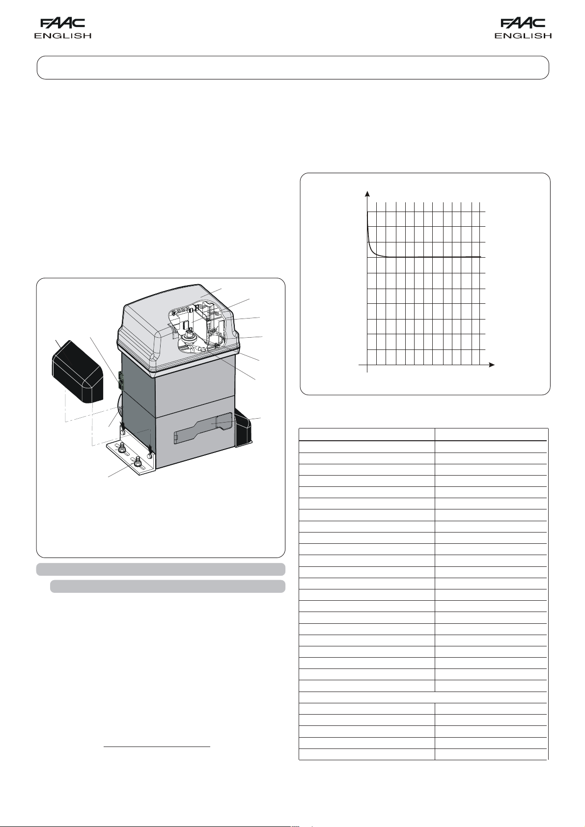
Securing corners
Pinion
Limit sensor switch
Operator cover
780 D Control board
Oil filling plug
Operator earthing
Lever operated release system
Protective side panels
Cover for 780D control board
Adjustment screw for
anti-crushing clutch
Fig. 1
1. DESCRIPTION AND TECHNICAL SPECIFICATIONS
1.1. MAXIMUM USE CURVE
The curve makes it possible to establish maximum work time (T)
according to use frequency (F).
E.g.: The 746 gearmotor can operate non-stop at 70% use
frequency.
To ensure efficient operation, operate in the work range below the
curve.
Important: The curve is obtained at a temperature of 24°C. Exposure
to the direct sun rays can reduce use frequency down to 20%.
Calculation of use frequency
The percentage of effective work time (opening + closing) compared
to total time of cycle (opening + closing + pause times).
Calculation formula:
%F =
Ta + Tc
X 100
Ta + Tc + Tp + Ti
Tab. 1 TECHNICAL SPECIFICATIONS OF 746 GEARMOTOR
MODEL 746
Power supply (Vac +6% -10% 50-60Hz) 230
Absorbed power (W) 300
Reduction ratio 1 : 30
Type of pinion Z20 - Z16
Rack Module 4 - step 12.566
Max. thrust (daN) 50 (Z20) - 62,5 (Z16)
Max. Torque (Nm) 20
Winding thermal protection (°C) 120
Use frequency 70% (see graph)
Oil quantity (l) 1,8
Type of oil FAAC XD 220
Operatine ambient temperature (°C) -20 ÷ +55
Gearmotor weight (Kg) 14
Protection class IP 44
Gate max. weight (Kg) 400 (Z20) - 600 (Z16)
Gate speed (m/min) 12 (Z20) - 9,6 (Z16)
Gate max. length (m) (time-out) 50 (Z20) - 40 (Z16)
Clutch twin-disk in oil bath
Protective treatment cataphoresis
Equipment 780D
Limit-switch MSL or inductive
Gearmotor overall dimensions LxHxD (mm) see Fig. 2
Electric motor technical specifications
RPM 1400
Power (W) 300
Absorbed current (A) 1.5
Starting capacitor (µF) 25
Power supply (Vac +6% -10%; 50-60Hz) 230
19
Page 4

2. DIMENSIONS
3. ELECTRIC EQUIPMENT (standard system)
To make the connections efficiently, allow the cables to
project by about 40 cm from the hole (Figs.5-6 ref.) of the
foundation plate.
Fig. 4
Fig. 2
Operator 746
with 780D equipment
Photocells
Key-operated push-button
Flashing lamp
Radio receiver
Fig. 3
4. INSTALLATION OF THE AUTOMATED SYSTEM
4. 1. PRELIMINARY CHECKS
To ensure safety and an efficiently operating automated system,
make sure the following conditions are observed:
• The gate structure must be suitable for automation. The following
are necessary in particular: wheel diameter must be in proportion
to the weight of the gate to be automated, an upper guide must
be provided, plus mechanical stop limits to prevent the gate
derailing.
• The soil must permit sufficient stability for the foundation plinth.
• There must be no pipes or electric cables in the plinth excavation
area.
• If the gearmotor is exposed to passing vehicles, install, if possible,
adequate means of protection against accidental impact.
• Check if an efficient earthing is available for connection to the
gearmotor.
Fig. 5
Fig. 6
Fig. 7
4.2. MASONRY FOR FOUNDATION PLATE
1) Assemble the foundation plate as shown in figure 4.
2) The foundation plate must be located as shown in figure 5 (right
closing) or figure 6 (left closing) to ensure the rack and pinion
mesh correctly.
3) Prepare a foundation plinth as shown in fig.7 and wall the
foundation plate, supplying one or more sheaths for routing
electric cables. Using a spirit level, check if the plate is perfectly
level. Wait for the cement to set.
4) Lay the electric cables for connection to the accessories and
power supply as shown in figure 3.
4. 3. MECHANICAL INSTALLATION
1) Assemble the securing corners and anti-vibration spacers on
the operator as shown in Fig. 8.
2) Open the cover, unscrewing the securing screws.
3) Place the operator on the plate, using the supplied washers and
nuts as shown in Fig. 9.
During this operation, route the cables through the duct inside
the lower half-casing of the operator (Fig.10 - Ref. A).
To access the electronic equipment, route the cables through
the appropriate hole, using the supplied rubber cable-clamp.
Make absolutely sure to unsheathe all the cables so that the
clamp holds single cables only (Fig.10 - Ref. B).
20
Page 5
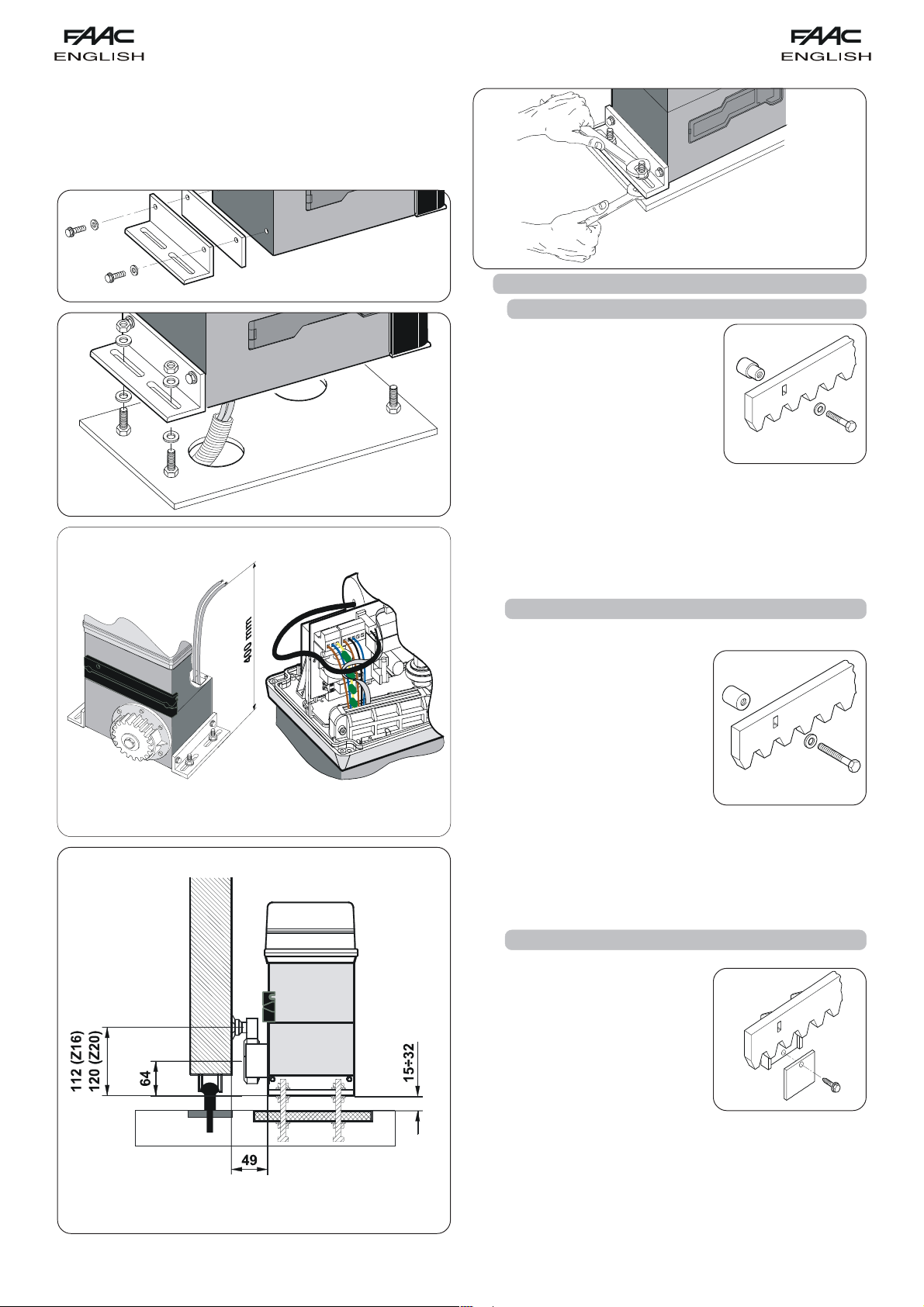
5) Secure the gearmotor to the foundation plate, tightening the
nuts as in Fig.12.
6) Prepare the operator for manual operating mode as described
in chapter 8.
Fig. 12
Fig. 8
Fig. 9
AB
Fig. 10
4. 4. INSTALLING THE RACK
4.4.1. STEEL RACK TO WELD (Fig.13)
1) Place the three threaded pawls on the
rack element, positioning them at the
top of the slot. In this way, the slot play
will enable any adjustments to be
made.
2) Manually take the leaf into its closing
position.
3)
Lay the first piece of rack level on the
pinion and weld the threaded pawl
on the gate as shown in figure15.
4) Move the gate manually, checking if the rack is resting on the
pinion, and weld the second and third pawl.
5) Bring another rack element near to the previous one, using a
piece of rack (as shown in figure 16) to synchronise the teeth of
the two elements.
6) Move the gate manually and weld the three threaded pawls,
thus proceeding until the gate is fully covered.
Fig. 13
4.4.2. STEEL RACK TO SCREW (Fig. 14)
1) Manually take the leaf into its closing position.
2) Lay the first piece of rack level on
the pinion and place the spacer
between the rack and the gate,
positioning it at the top of the slot.
3) Mark the drilling point on the gate.
Drill a Ø 6,5 mm hole and apply
thread with a Ø 8 mm male tap.
Screw the bolt.
4) Move the gate manually, checking
if the rack is resting on the pinion,
and repeat the operations at point
3.
5) Bring another rack element near to the previous one, using a
piece of rack (as shown in figure 16) to synchronise the teeth of
the two elements.
6) Move the gate manually and carry out the securing operations
as for the first element, thus proceeding until the gate is fully
covered.
Fig. 14
Fig. 11
4.4.3. NYLON RACK TO SCREW (Fig.14bis)
1) Manually take the leaf into its
closing position.
2) Lay the first piece of the rack level on
the pinion and mark the drilling point
on the gate; drill Ø 4 mm and screw
the self-tapping screw 6 x 20 mm to
the relevant reinforcing plate.
3) Move the gate manually, checking
if the rack is resting on the pinion,
and repeat the operations at point
2.
4) Bring another rack element near to the previous one, using
a piece of rack (as shown in figure 16) to synchronise the
teeth of the two elements.
5) Move the gate manually and carry out the securing
operations as for the first element, thus proceeding until the
gate is fully covered.
Fig. 14bis
21
Page 6
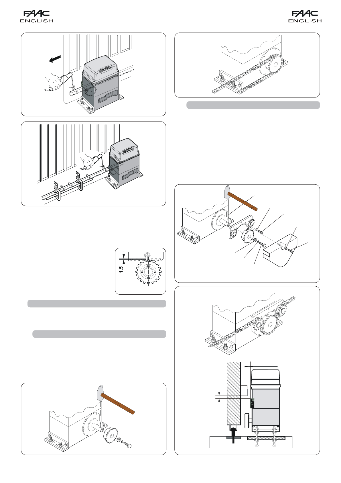
Fig. 19
Fig. 15
Fig. 16
Notes on rack installation
• Make sure that, during the gate travel, all the rack elements do
not exit the pinion.
• Do not, on any account, weld the rack elements either to the
spacers or to each other.
• When the rack has been installed, to ensure it meshes
correctly with the pinion, we advise
you to lower the gearmotor position
by about 1.5 mm (Fig.17).
• Manually check if the gate
habitually reaches the mechanical
stop limits and make sure there is no
friction during gate travel.
• Do not use grease or other lubricants
between rack and pinion.
Fig. 17
4.5.2. MOD. 746 ER RF (Figs. 20 - 21)
1) Insert the spring pin on the shaft, using a hammer.
2) Fit the idle transmissions bracket on the gearmotor flange,
using the four screws (M5 x 12) and the appropriate
washers , in the kit as shown in Fig. 20.
3) Fit the chain pinion on the shaft, making the pinion seats
coincide with the spring pin and tighten the screw and
the appropriate washers and .
4) Pass the chain as shown in Fig. 21 ref. A and install the
housing with screw and washer as in Fig. 20.
5) In case of operators with MLS limit switches, arrange the
supports for the positioning of the magnets supplied while
observing the dimensions given in fig. 21 ref. B.
Fig. 20
4.5. INSTALLATION OF CHAIN PINIONS
In the versions for applications with chain and idle transmissions,
a Z16 or Z20 chain pinion must be installed. Proceed as follows:
4.5.1. MOD. 746 ER CAT (Figs. 18 - 19)
1) Insert the spring pin on the shaft, using a hammer.
2) Fit the chain pinion on the shaft, making the pinion seats
coincide with the spring pin and tighten the screw with the
appropriate washers.
Fig. 18
A
5÷12 mm
0÷10 mm
B
Fig. 21
22
Page 7

5. CONTROL BOARD 780D
5. 3. LAYOUT AND COMPONENTS
5. 1. WARNINGS
Important: Before attempting any work on the control board
(connections, maintenance), always turn off power.
- Install, upstream of the system, a differential thermal breaker with
adequate tripping threshold.
- Connect the earth cable to the terminal on J7 connector of the board,
and to the bush on the operator (figs. 22 and 40).
- Always separate power cables from control and safety cables (pushbutton, receiver, photocells, etc.). To avoid any electric noise, use
separate sheaths or a shielded cable (with earthed shield).
DL SIGNALLING AND PROGRAMMING DISPLAY
Led INPUTS STATUS CONTROL LED
J1 LOW VOLTAGE TERMINAL BOARD
J2 CONNECTOR FOR DECODER/MINIDEC/RP RECEIVER
J5 CONNECTOR FOR MOTOR STARTING CAPACITOR
J6 MOTOR AND FLASHING LAMP CONNECTION TERMINAL BOARD
J7 230 Vac POWER SUPPLY TERMINAL BOARD
J8 DOUBLE CONNECTOR J8 - LIMIT-SWITCH QUICK FIT
F1 MOTOR AND TRANSFORMER PRIMARY WINDING FUSE (F 5A)
F2 LOW VOLTAGE AND ACCESSORIES FUSE (T 800mA)
F "F" PROGRAMMING PUSH-BUTTON
5. 2. TECHNICAL SPECIFICATIONS
Power supply V~ (+6% -10%) 230
Absorbed power (W) 10
Motor max. load (W) 1000
Accessories max. load (A) 0,5
Operating ambient temperature -20 °C +55 °C
Protection fuses 2 (see fig. 22 and par. 5.3)
Function logics: Automatic / “Stepped” automatic / Semi-automatic / Safety
devices / Semi-automatic B / Dead-man C / “Stepped” semi-automatic / Mixed B/C
logic
Work time Programmable (from 0 to 4,1 min.)
Pause time Programmable (from 0 to 4,1 min.)
Thrust force Adjustable over 50 levels
Terminal board inputs: Open - Partial Open - Opening safety devices - Closing safety
devices - Stop - Edge - Power supply+Earth
On-connector inputs Opening and closing limit-switch -
Motor capacitor
Terminal board outputs: Flashing lamp - Motor - 24 Vdc accessories power supply
- 24 Vdc indicator-light / Timed output / Electric lock command - 'traffic lights' - Fail
safe
Rapid connector 5-pin card connection for Minidec, Decoder or RP receivers
Programming 3 keys (+, -, F) and display, "basic" or "advanced" mode
Basic mode programmable functions: Function logic - Pause time - Thrust Force
- Opening-closing direction
Advanced mode programmable functions: Torque at initial thrust - Braking - Fail safe
- Pre-flashing - Indicator-light/Timed output/Electric lock or 'traffic lights' command Opening and closing safety devices logic - Encoder/ Anti-crushing sensitivity Decelerations - Partial opening time - Work time - Assistance request - Cycle counter
– "–" PROGRAMMING PUSH-BUTTON
+ "+" PROGRAMMING PUSH-BUTTON
J1 CONNECTOR
1 OPEN A (total opening)
2 OPEN B (partial opening)
3 FSW-OP (opening safety devices)
4 FSW-CL (closing safety devices)
5 STOP
6 SAFE (“edge” safety devices)
7 - (negative for power supply to accessories)
8 - (negative for power supply to accessories)
9 +24V (supply to accessories)
10 +24V (supply to accessories)
11 FSW-TX (negative for emitting photocells - FAILSAFE)
12 W.L. (negative for indicator light)
J7
F1
J6
J5
F2
J8
23
Led
+
–
F
J1
DL
Led
J2
Fig. 22
Page 8

5.4 . ELECTRIC CONNECTIONS
J
5
O
O
P
P
E
E
N
N
O
A
P
B
J1
S
A
F
C
E
L
+
+
BLUE
230Vac
50-60Hz
230 Vac (max.
60W)
Capacitor
LIMIT-SWITCH
Opening safety devices:
they are tripped when an obstacle is
detected only during gate opening movement. They
cause immediate closure and resumption of opening
motion on release (see programming in par. 5.5.2.)
Closing safety devices:
they are tripped when an obstacle is
detected only during gate closing movement. They
cause re-opening, either immediate or on release
(see programming in par. 5.5.2.)
Opening/closing safety devices:
they are tripped during the
gate opening and closing movements. They cause
stopping and restart motion on release.
"Edge" safety devices:
they are tripped during the gate opening
and closing movements. They cause immediate
reversal of motion and stopping after two seconds.
Encoder:
it is tripped if there is an obstacle during gate opening
and closing movements. It causes immediate reversal
of motion and stopping after two seconds.
N.B. If two or more safety devices have the same function
(opening, closing, opening and closing, edge), the contacts
must be connected to each other in series (fig. 25).
N.C. contacts must be used.
N.B: If safety devices are not used, jumper connect the terminals
as shown in fig. 26.
The most common photocell and safety device lay-outs are
shown below (from fig. 27 to fig. 34).
24 Vcc
max. 3W
For connection of the
PARTIAL
OPEN
photocells and safety
devices, see paragraph
5.4.1.
TOTAL
OPEN
STOP
Fig. 23
5.4.1. Connection of photocells and safety devices
Before connecting the safety devices and photocells we advise
you to select the type of operation according to the movement
area they have to protect (see fig.24 for example):
Connection of two N.C. contacts in series
(e.g. Photocells, Stop, Edge, etc.)
Fig. 25
Connection of no safety device
L
OPC
N
N
E
E
B
A
P
P
O
O
E
F
A
S
+
+
Fig. 26
Connection of a closing safety device and an opening
N
N
E
E
A
P
P
O
O
OPC
B
safety device
L
E
F
A
S
+
+
Closing
photocells
Closing photocells
opening/closing
"Edge" safety devices
Opening or
photocells
Fig. 24
24
Connection of an "edge" safety device
L
OPC
N
N
E
E
B
A
P
P
O
O
E
F
A
S
+
+
Fig. 27
Fig. 28
Page 9

Connection of a pair of opening photocells
P
L
O
C
N
N
E
E
B
A
P
P
O
O
E
F
A
S
+
+
Connection of a pair of closing photocells
P
L
O
C
N
N
E
E
B
A
P
P
O
O
E
F
A
S
+
+
Fig. 29
Connection of two pairs of closing photocells and two
edge safety devices
L
OPC
N
N
E
E
B
A
P
P
O
O
E
F
A
S
+
+
Fig. 32
Fig. 30
Connection of a pair of opening photocells, a pair of closing
photocell and an edge safety device
L
OPC
N
N
E
E
B
A
P
P
O
O
E
F
A
S
+
+
RX OPTX OP
Connection of a pair of closing photocells, a pair of opening
photocells and a pair of opening/closing photocells
P
L
O
C
N
N
E
E
B
A
P
P
O
O
RX OP TX OP
E
F
A
S
+
+
RX O P/CLTX OP/CL
Fig. 31
Fig. 33
25
Page 10

Connection of a pair of closing photocells and a pair of
Connection of two N.O. contacts in parallel
opening/closing photocells
L
OPC
N
N
E
E
B
A
P
P
O
O
TX OP/CL
(e.g. Open A, Open B)
E
F
A
S
RX O P/CL
+
+
Fig. 34
Fig. 35
5.4.2. J7 Terminal board - Power supply (fig. 23)
POWER SUPPLY (terminals PE-N-L):
PE: Earth connection
N:Power supply ( Neutral )
L:Power supply ( Line )
NB.: For correct operation, the board must be connected to the
earth conductor in the system. Install an adequate differential
thermal breaker upstream of the system.
5.4.3. J6 Terminal board - Motors and flashing lamp
(fig. 23)
MOTOR - (terminals MOT-C, MOT-1, MOT-2): Motor connection
(see Par. 6.5).
LAMP - (terminals LAMP L, LAMP N): Flashing lamp output 230Vac
max 60W.
5.4.4. J1 Terminal board - Accessories (fig. 23)
Consult the relevant tables for a detailed description of
operation in the different logics
OPEN A - “Total Opening” command (terminal 1): any pulse
OPEN B - “Partial opening” or “Closing” command (terminal 2): any
generator (push-button, detector, etc.) which, by closing a
contact, commands total opening and/or closing of the
gate leaf.
To install several total opening pulse generators, connect
the N.O. contacts in parallel (fig. 35).
pulse generator (push-button, detector, etc.) which, by
closing a contact, commands partial opening and/or
closing of the gate leaf.
In the B, C and B/C logics, it always
commands gate closure.
To install several partial opening pulse generators, connect
the N.O. contacts in parallel (fig.35).
FSW OP - Opening safety devices contact (terminal 3): The purpose
of the opening safety devices is to protect the leaf movement
area during opening. During opening, in the A-AP-S-E-EP
logics the safety devices reverse the movement of the gate,
or stop and restart the movement when it is released (see
advanced programming in Chpt. 5.5.2). During the opening
cycle in logics B, C and B/C, they interrupt movement.
They
never operate during the closing cycle.
If the Opening safety devices are engaged when the gate
is closed, they prevent the opening movement.
To install several safety devices, connect the N.C. contacts in
series (fig.25).
NB.: If no opening safety devices are connected, jumper
connect inputs FSW OP and -TX FSW (fig. 26).
FSW CL - Closing safety devices contact (terminal 4): The purpose
of the closing safety devices is to protect the gate movement
area during closing. During closing, in the A-AP-S-E-EP
logics, the safety devices reverse the movement of the
gate, or stop and reverse the movement when it is released
(see advanced programming in Chpt. 5.5.2). During the
closing cycle in logics B, C and B/C, they interrupt movement.
They never operate during the opening cycle. If the Closing
safety devices are engaged when the gate is open, they
prevent the closing movement.
To install several safety devices, connect the N.C. contacts
in series (fig.25).
NB.: If no closing safety devices are connected, jumper
connect terminals FSW CL and -TX FSW
(fig. 26).
STOP - STOP contact (terminal 5): any device (e.g. a push-button)
which, by opening a contact, stops gate movement.
To install several STOP devices, connect the N.C. contacts
in series (fig. 25).
NB.: If STOP devices are not connected, jumper connect
the STOP and - terminals.
SAFE - EDGE safety device contact (terminal 6): The purpose of the
"edge" safety device is to protect the leaf movement area
during opening/closing. In all logics, during opening and
closing, the safety device reverses gate movement for 2
seconds. If the safety devices operate again during the 2seconds reversing time, it stops movement (STOP) without any
reversing.
If the Edge safety device is engaged while the gate is closed
or open, it prevents movement.
To install several safety devices, connect the N.C. contacts in
series (fig.25).
NB.: If edge safety devices are not connected, jumper
connect the SAFE and - inputs (fig. 26).
Negative for power supply to accessories (terminals 7
–
and 8)
+ 24 Vdc - Positive for power supply to accessories (terminals
9 and 10)
Important: Accessories max. load is 500 mA. To calculate absorption
values, refer to the instructions for individual accessories.
26
Page 11

TX -FSW - Negative for power supply to photocell transmitters
W.L. - Power supply to indicator light / timed exit / electric lock
(terminal 11)
If you use this terminal for connecting the negative for
supplying power to the photocell transmitters, you may, if
necessary, also use the FAIL SAFE function (see advanced
programming in Chpt. 5.5.2).
If this function is enabled, the equipment checks operation
of the photocells before every opening or closing cycle.
/ 'traffic lights' (terminal 12)
Connect any 24 Vdc - 3 W max indicator light, timed exit,
command device for electric lock or 'traffic lights' between
this terminal and the +24V (see advanced programming
in Chap. 5.5.2). To avoid geopardising correct operation
of the system,
do not exceed the indicated power.
5.4.5. J2 Connector - Rapid connection to Minidec,
Decoder and RP
This is used for rapid connection of Minidec, Decoder and RP
receivers (see fig. 36, 37 and 38). Fit the accessory with the
components side toward connector J1. Insert and remove after
cutting power.
5.4. 6. J5 Connector -Rapid connection to Capacitor
Quick-fit connector for connecting the motor starting capacitor.
5.5. PROGRAMMING
To program operation of the automated system, access the
"PROGRAMMING" mode with keys F,+ and -, and using the display
on the equipment.
Attention: before attempting to power up the system, we advise
you to re-position the equipment's cover, to avoid coming into
contact with high voltage parts, and to use the push-buttons on
the cover to activate the keys (fig. 39).
+
Programming is divided in two parts: BASIC and ADVANCED.
F-
Fig. 39
5.4.7. Double connector J8 - Limit-switch quick fit
Quick-fit connector for connecting the limit -switch. For connecting
both the MLS limit-switch and the inductive limit-switch (fig. 23
ref.) to the equipment.
PLUS
MINIDEC
Fig. 36
Fig. 37
5.5.1. BASIC PROGRAMMING
To access BASIC PROGRAMMING, press key F:
•if you press it (and hold it down), the display shows the name
of the first function.
•if you release the key, the display shows the value of the
function that can be modified with keys + and -.
•if you press F again (and hold it down), the display shows the
name of the next function, etc.
•when you reach the last function, press F to exit the program,
and the display resumes showing the gate status.
The following table shows the sequence of functions accessible in
BASIC PROGRAMMING:
BASIC PROGRAMMING
Display Function Default
FUNCTION LOGICS (see table of logics):
= Automatic
= "Stepped" automatic
= "Safety" Automatic
= Semi-automatic
= "Stepped" Semi-automatic
= Dead-man
= "B" Semi-automatic
= Mixed Log. (B opening / C closing)
F
RP
Fig. 38
27
PAUSE TIME:
This has effect only if the automatic logic was
selected. Adjustable from to sec. in
one-second steps.
Subsequently, display changes to minutes
and tens of seconds (separated by a point)
and time is adjusted in 10-second steps, up
to the maximum value of minutes.
E.g. if the display shows
min. and 50 sec.
, pause time is 2
Page 12

Display Function Default Display Function Default
FORCE:
Adjusts Motor thrust.
= minimum force
= maximum force
OPENING DIRECTION:
Indicates the gate opening movement and
makes it possible not to change the motor
connections on the terminal board.
= Rightward opening movement
= Leftward opening movement
STATUS OF AUTOMATED SYSTEM:
Exit from programming, save data, and return
to gate status viewing.
= Closed
= Now opening
= At "STOP"
= Open
= Pause
= "FAIL SAFE" tripped
= Now closing
= Now reversing
= Photocells tripped
5.5.2. ADVANCED PROGRAMMING
To access ADVANCED PROGRAMMING, press key F and, as you hold
it down, press key +:
•if you release key + , the display indicates the name of the first
function.
•if you release key F too, the display shows the value of the
function that can be modified with keys + and -.
•if you press key F (and hold it down), the display shows the
name of the next function, and if you release it, the value that
can be modified with keys + and - is shown.
•when you reach the last function, press F to exit the program,
and the display resumes showing the gate status.
The following table shows the sequence of functions accessible in
ADVANCED PROGRAMMING:
ADVANCED PROGRAMMING
F
+
+
Display Function Default
MAXIMUM TORQUE AT INITIAL THRUST:
The motor operate at maximum torque (ignoring
the torque setting) at start of movement. Useful
for heavy leaves.
= Active
= Disabled
FINAL BRAKING:
When the gate engages the opening or
closing limit-switch, a braking stroke can be
selected to ensure the leaf is stopped
immediately. If decelerations are selected,
braking starts when they finish.
At value, braking is disabled.
Time can be adjusted from to in
0.01-second steps.
= Braking disabled
from to = Timed braking
FAIL SAFE:
If this function is activated, it enables a function
test of the photocells before any gate
movement. If the test fails (photocells not
serviceable signalled by value on the
display), the gate does not start moving.
= Active
= Disabled
PRE-FLASHING (5 s):
Activates the flashing lamp for 5 seconds before
start of movement.
= Disabled
= Only before opening
= Only before closing
= Before every movement
INDICATOR-LIGHT:
If is selected, the output functions as a
standard indicator-light (lighted at opening
and pause, flashing at closing, and off when
gate closed).
Courtesy light: Different figures correspond
to timed activation of the output, which can
be used (by a relay) to power a courtesy
lamp. Time can be adjusted from to
sec. in 1-second steps, and from to
min. in 10-second steps.
Electric lock command and 'traffic lights'
functions:
If you press key - from the setting, the
command for the closing electric lock is
activated;
If you press - again, the command for the
closing and opening electric lock is set;
if you press the - key again, you can set the
'traffic lights' functions and .
= Standard indicator-light
from to = Timed output.
= electric lock command before opening
movement
= electric lock command before
opening and closing movements
= 'traffic lights' function: the output is
active in "open" and "open on pause" status
and is disabled 3 seconds before the closing
manoeuvre starts.
Note: there is 3 seconds of pre-flashing before
the closing manoeuvre.
= 'traffic lights' function: the output is
active only in "closed" status.
Attention: do not exceed the output's
maximum load (24Vdc-3W). If necessary,
use a relay and a power supply source
outside the equipment.
CLOSING PHOTOCELLS LOGIC:
Select the tripping mode of the closing
photocells.
They operate for the closing movement only:
they stop movement and reverse it when they
are released, or they reverse it immediately.
= Reverse on release
= Reverse immediately to opening
28
Page 13

Display Function Default Display Function Default
OPENING PHOTOCELLS LOGIC:
Select the tripping mode of the opening
photocells.
They operate for the opening movement
only: they stop the movement and restart it
when they are released, or they reverse it
immediately.
= Reverse immediately to closing
= Restart movement on release
ENCODER:
If the encoder is used, you may select its presence.
If the encoder is present and enabled,
"decelerations" and "partial opening" are
controlled by the encoder (see relevant
paragraphs).
The encoder operates as an anti-crushing device:
If the gate strikes an obstacle during opening or
closing, the encoder immediately reverses gate
leaf movement for 2 seconds. If the encoder
operates again during the 2-seconds reversing
time, it stops movement (STOP) without
commanding any reversing. If no sensor is
supplied, the parameter must be set on . If
there is the encoder, adjust the sensitivity of the
anti-crushing system, by varying the parameter
between (maximum sensitivity) and
(minimum sensitivity).
PARTIAL OPENING:
You can adjust the width of partial leaf
opening.
Time can be adjusted from to in
1 second steps.
If an encoder is used, the adjustment is not
determined by time but by motor revs, thus
obtaining greater partial-opening precision.
For example, with pinion Z20, partial opening
can vary from about 60 cm to 4 m.
WORK TIME (tome-out):
We advise you to set a value of 5 to 10
seconds over the time taken by the gate to
travel from the closing limit-switch to the
opening limit-switch and vice versa.
Adjustable from to sec. in onesecond steps.
Subsequently, display changes to minutes
and tens of seconds (separated by a point)
and time is adjusted in 10 second steps, up to
a maximum value of minutes.
Attention: the set value does not exactly
match the motor's maximum operating time,
because the latter is modified according to
the performed deceleration spaces.
from to = Encoder active and
sensitivity adjustment
= Encoder disabled
Pre-limit switch DECELERATION:
You can select gate deceleration before the
opening and closing limit-switches have been
tripped.
Time can be adjusted from to in
0.1-second steps.
If an encoder is used, the adjustment is not
determined by time but by motor revs, thus
obtaining greater deceleration precision.
= Deceleration disabled
from to = Deceleration enabled
Post-limit switch DECELERATION:
You can select gate deceleration after the
opening and closing limit-switches have been
tripped.
Time can be adjusted from to in
0.1-second steps.
If an encoder is used, the adjustment is not
determined by time but by motor revs, thus
obtaining greater deceleration precision.
ASSISTANCE REQUEST (combined with next
function):
If activated, at the end of countdown
(settable with the next function i.e. "Cycle
programming") it effects 2 sec. (in addition to
the value already set with the PF function) of
pre-flashing at every Open pulse (job
request). Can be useful for setting scheduled
maintenance jobs.
= Active
= Disabled
CYCLE PROGRAMMING:
For setting countdown of system operation
cycles. Settable (in thousands) from to
thousand cycles.
The displayed value is updated as cycles
proceed.
This function can be used to check use of the
board or to exploit the "Assistance request".
GATE STATUS:
Exit from programming, data saving, and
return to viewing gate status (see par.
5.5.1.).
Note 1: to reset the programming default settings, check if the
edge input is closed (SAFE LED ON), and simultaneously
press keys +, - and F, holding them down for 5 seconds.
= Deceleration disabled
from to = Deceleration enabled
Note 2: modification of programming parameters comes into
effect immediately, whereas definitive memory storage
occurs only when you exit programming and return to
gate status viewing. If the equipment is powered down
before return to status viewing, all modifications will be
lost.
29
Page 14

6. START-UP
6.1 . ELECTRIC CONNECTIONS
Make all electrical connections to the board as in chapter 5,
including earthing of the operator (Fig. 40).
Fig. 40
6. 2. DEFINITION OF OPENING DIRECTION AND OPERATION
OF LIMIT-SWITCH LEDS
Power up the system and set the opening direction on the
board (see par. 5.5.1).
If opening direction is
OPENING limit-switch LED = FC1
CLOSING limit-switch LED = FC2
RIGHTWARD ( ):
Attention: due to the powerful magnetic fields the supplied
magnets produce, the magnets can damage magnetic band
components (credit cards, magnetic tapes, floppy disks, etc)
and electronic and mechanical equipment (e.g. watches, LCD
screens). We advise you not to bring them near to objects that
could be damaged if 'immersed' in a magnetic field.
Notes on magnet positioning
• To ensure correct operation, allow at least 2 cm from the
mechanical stop limit in the gate stop position. Carry out this
check after determining the values of the pre- and post-limit
switch decelerations (see par. 5.5.2.) and after running at least
one complete cycle of the automated system.
• The distance between the limit-switch and magnets must be
from 5 to 12 mm.
• Magnets should be fitted on the rack and not on the fixing
screws.
If necessary, position the magnet at the side of the screw
and adjust decelerations (parag. 5.5.2) in order to obtain
the correct stop point.
FC1
If opening direction is
OPENING limit-switch LED = FC2
CLOSING limit-switch LED = FC1
LEFTWARD ( ):
6.3. DETERMINING THE STOP POINTS AT TRAVEL LIMIT
Operator 746 has a limit sensor switch which, by detecting the
transit of a reference applied to the rack, commands the gate
motor to stop. The device can be MLS (fig. 41) or inductive (fig.
42).
6.3.1. MLS limit-switch
The MLS limit sensor switch detects the transit of two magnets
fitted on the side of the rack facing the operator.
Procedure for correct positioning of the two supplied magnets:
1) Check if the operator is in manual mode (see chapter 8).
2) Manually take the gate to opening position, leaving 2 - 5 cm
from the travel limit mechanical stop.
3) Fit the magnet (without removing the protective film from the
adhesive side) on the side of the rack facing the operator,
aligning the upper edges. Slide the magnet on the rack in
opening direction until the relevant LED goes off (Fig. 22 and
41), then move the magnet forward a further 45 mm.
4) Manually take the gate to closing position, leaving 2 - 5 cm
from the travel limit mechanical stop.
5) Fit the magnet (without removing the protective film from the
adhesive side) on the side of the rack facing the operator,
aligning the upper edges. Slide the magnet on the rack in
closing direction until the relevant LED goes off (Fig. 22 and 41),
then move the magnet forward by about a further 45 mm.
6) Take the gate to its halfway travel point and relock the system
(see chapter 9).
7) Find out the desired pre- and post-limit-switch deceleration
values (see parag. 5.5.2) and run the automated system for at
least one complete cycle.
8) Check if the gate stops at about 2 - 5 cm from its mechanical
stop point. If necessary, correct the position of the magnets
and check if the stop point is correct.
9) Mark the position of the magnets on the rack, and remove
them.
10) Clean the rack on its fitting points, remove the film on the
adhesive parts of the magnets (fig. 41 ref. 1) and re-position the
magnets with the adhesive strip in contact with the rack (fig. 41
ref. 2).
FC2
1
2
Fig. 41
6.3.2. Inductive limit-switch
Operator 746 has an inductive limit-switch which detects the
transit of the two steel plates fitted on the top of the rack.
Procedure for correct positioning of the two supplied steel plates:
1) Assemble the limit-switch by centring the plate with respect to
threaded pins of the support (Fig. 42).
2) Check if the operator is in manual operating mode (see
chapter 8).
3) Manually move the gate to opening position, allowing 2 - 5 cm
from the mechanical stop limit.
4) Allow the plate to move on the rack in opening direction until
the relevant LED goes OFF (Figs. 22 and 42); next, move the
plate forward by about another 45 mm and secure it to the rack
by tightening the screws.
5) Manually move the gate to closing position, allowing 2 - 5 cm
from the mechanical stop limit.
6) Allow the plate to move on the rack in closing direction until the
relevant LED goes OFF (Figs. 22 and 42); next, move the plate
forward by about another 45 mm and secure it to the rack by
tightening the screws.
FC1
FC2
30
Fig. 42
Page 15

Notes on plate positioning
• To ensure correct operation, allow at least 2 cm from the
Ü The operator is supplied with the clutch set to maximum level.
mechanical stop limit in the gate stop position. Carry out this
check after determining the values of the pre- and post-limit
switch decelerations (see par. 5.5.2.) and after running at least
3) Power up the automated system and check that the torque you
one complete cycle of the automated system.
• The distance between the limit-switch and the plates must be <
5mm.
• For nylon racks, use the plate only (without support), securing it
directly to the rack by the self-tapping screws. Make the above
mentioned adjustments.
Note
: a steel core is situated 5 mm under the surface of the
nylon rack. Therefore, drill until you reach the steel core and
screw with the self-tapping screws.
6.4. CHECK OF INPUTS
The table below shows the status of the LEDs in relation to to the
status of the inputs.
Note the following:
LED
LIGHTED
= closed contact
LED
OFF
= open contact
Check the status of the LEDs as per Table.
Tab. 2 Operation of the signalling status LEDs
LEDS LIGHTED OFF
OP-A Command activated Command inactive
OP-B Command activated Command inactive
FC1 Limit-switch free Limit-switch engaged
FC2 Limit-switch free Limit-switch engaged
FSW OP Safety devices disengaged Safety devices engaged
FSW CL Safety devices disengaged Safety devices engaged
STOP Command inactive Command activated
SAFE Safety devices disengaged Safety devices engaged
ENC Flashes while the motor rotates
Take care over the setting of the post-limit-switch deceleration
and braking: If deceleration is too long and braking is insufficient,
the reference fitted on the gate's rack (magnet or steel plate)
can overtake the sensor until the latter is disengaged. When
the gate stops, check if only the limit-switch involved is engaged.
The relevant LED must be OFF - if it went OFF and then ON
again, or if both the limit-switch LEDS are OFF, you must reduce
the post-limit-switch deceleration value and/or increase
braking value (see par.5.5.2).
Check correct operation of all the safety and anti-crushing
devices (ENCODER sensor), and of the accessories used on the
system.
7. FINAL OPERATIONS
At end of installation, apply the danger sticker on the top of
the cover (Fig. 45).
NB.: The status of the LEDs while the gate is closed at rest are shown in bold.
If opening direction is leftward, the status of LEDS FC1 and FC2 is reversed.
To reduce torque, turn the screw anti-clockwise.
Therefore, you must initially turn the screw anti-clockwise to
reach the best setting.
have just set is correct.
Fig. 44
6.7. CHECK OF STOP POINTS
6.8. SAFETY DEVICES AND ACCESSORIES CHECK
Fig. 45
6.5. CHECK OF MOTOR CONNECTION
Check if the motor wiring
is as shown in Fig. 43 (standard connection).
MOT 2
MOT 1
MOT
COM
J6
BROWN
BLACK
BLUE
M
Fig. 43
6. 6. ADJUSTMENT OF MECHANICAL CLUTCH
In addition to its electronic safety devices (encoder and force
adjustment), the 746 operator is also equipped with a mechanical
clutch.
For gate force and the encoder, please consult paragraphs 5.5.1
and 5.5.2.
Procedure for adjusting the operating threshold of the mechanical
clutch (you are recommend to set it to conform with current
regulations):
1) Cut electrical power to the automated system.
2) Keep the motor shaft locked with a wrench and turn the clutch
adjustment screw with an Allen wrench or screwdriver as shown
in Fig. 44.
To increase torque, turn the screw clockwise.
Snap-fit the side panels, fit the equipment's cover and fit the
cover with the supplied screws (Fig. 46).
Remove the vent stop screw (fig. 47).
Hand the "User's Guide" to the Customer, explain correct
operation and use of the gearmotor, and indicate the
potentially dangerous areas of the automated system.
Fig. 46
31
Page 16

Fig. 47
8. MANUAL OPERATION
If the gate has to be operated manually due to a power cut
or malfunction of the automated system, use the release
device as follows:
1) Open the protection door and fit the supplied key in the
lock (Fig. 48).
Fig. 48
2) Turn the key clockwise and pull the release lever as shown
in Fig. 49.
3) Open and close the gate manually.
Fig. 50
12.MAINTENANCE
Check the operational efficiency of the system at least once
every 6 months, especially as regards the efficiency of the
safety and release devices (including operator thrust force).
12.1. DISASSEMBLING THE TRANSFORMER-BOARD UNIT
If you have to disassemble the transformer-board unit, proceed
as follows:
Remove all terminal boards and connectors from the board.
Unscrew the 3 securing screws of the board and the 2 of the
transformer. Lift the unit up and gently remove the transformer
from the couplings on the board as shown in Fig. 51.
Fig. 49
9. RESTORING NORMAL OPERATION
To prevent an involuntary pulse from activating the gate during the
manoeuvre, cut power to the system before re-locking the operator.
1) Re-close the release lever.
2) Turn the key anti-clockwise
3) Remove the key and close the lock protection door.
4) Move the gate until the release meshes.
10. INSTALLING THE CN 60E CONTROL UNIT (OPTIONAL)
The operator is designed to house (with the aid of a DIN bar)
the CN 60E control unit of the safety conductive edge. Cut the
DIN bar to measure and secure it to the operator with two
screws in the appropriate holes and attach the CN 60E control
unit to it (Fig. 50).
For connection and operation, refer to the specific instructions.
11 .SPECIAL APPLICATIONS
There are no special applications.
Fig. 51
12.2. OIL TOP-UPS
Periodically check oil level inside the operator.
A once-a-year check is enough for medium or low use frequency.
For heavier duty, every 6 months is recommended.
To access the tank, temporarily remove the oil filling plug (Fig.
52).
Oil level (visually checked) must be in line with the copper windings
of the electric motor.
To top up, pour in oil up to the required level.
Use FAAC XD 220 oil only.
Fig. 52
13.REPAIRS
For any repairs, contact the FAAC authorised Repair Centres.
32
Page 17

)2("2rofnepootsesreveR
)1(emitesuapsdaoleR
)2("2rofesolcotsesreveR
)delbasidNEPO(
)2("2rofnepootsesreveR
)2("2rofesolcotsesreveR
emitesuapsdaoleR
)delbasidNEPO(
)2("2rofnepootsesreveR
)1(emitesuapsdaoleR
)2("2rofesolcotsesreveR
)delbasidNEPO(
)2("2rofnepootsesreveR
)2("2rofesolcotsesreveR
)delbasidNEPO(
tceffeoN
otsesrever,esaelerno,dnaskcoL
)1(emitesuapsdaoleR
)delbasidNEPO(
nepo
)3()1(emitesuapsdaoleR
.2.5.5hpargarapees
tceffeoN
)delbasidANEPO.gnpo.trapnofi(
)NEPOsevas(
tceffeoN
tceffeoN
)delbasidNEPO(
tceffeoN
seunitnoc,esaelerno,dnaskcoL
gninepo
tceffeoN
)delbasidNEPO(
tceffeoN
otsesrever,esaelerno,dnaskcoL
emitesuapsdaoleR
)delbasidNEPO(
nepo
)3(emitesuapsdaoleR
.2.5.5hpargarapees
)delbasidNEPO(
tceffeoN
)delbasidANEPO.gnpo.trapnofi(
)NEPOsevas(
tceffeoN
tceffeoN
)delbasidNEPO(
tceffeoN
seunitnoc,esaelerno,dnaskcoL
gninepo
tceffeoN
)delbasidNEPO(
tceffeoN
otsesrever,esaelerno,dnaskcoL
"5retfasesolc,esaelernO
)delbasidNEPO(
nepo
NEPO("5retfasesolc,esaelernO
.2.5.5hpargarapees
)3()delbasid
tceffeoN
)delbasidANEPO.gnpo.trapnofi(
)NEPOsevas(
tceffeoN
tceffeoN
)delbasidNEPO
tceffeoN
seunitnoc,esaelerno,dnaskcoL
gninepo
)NEPOsevas(
tceffeoN
tceffeoN
)delbasidNEPO(
)delbasidNEPO(
tceffeoN
tceffeoN
otsesrever,esaelerno,dnaskcoL
nepo
.2.5.5hpargarapees
)delbasidNEPO(
)3(tceffeoN
tceffeoN
)delbasidANEPO.gnpo.trapnofi(
)NEPOsevas(
tceffeoN
tceffeoN
)delbasidNEPO(
tceffeoN
seunitnoc,esaelerno,dnaskcoL
gninepo
tceffeoN
)delbasidNEPO(
tceffeoN
)delbasidNEPO(
tceffeoN
noitarepo
spotS
retfasesolcdnaemitgninepo
laitrapehtroffaelsnepO
)1(emitesuap
)1(yletaidemmifaelehtsnepo-eR
)3()1(emitesuapsdaoleR
)3(faelehtsesolC
)3()1(tceffeoN .2.5.5hpargarapeestceffeoN
sesolcdnafaelehtsnepO
)1(emitesuapretfati
)delbasidNEPO(
tceffeoN
)delbasidNEPO(
tceffeoN
noitarepo
spotS
retfasesolcdnaemitgninepo
laitrapehtroffaelsnepO
emitesuap
)3(noitarepospotS
sesolcdnafaelehtsnepO
emitesuapretfati
,degagnesecivedytefaSgnisolChtiw(faelehtsesolC
yletaidemmifaelehtsnepo-eR
)3()eslupdn2ehttasnepo
)3(noitarepospotS .2.5.5hpargarapeestceffeoN
)delbasidNEPO(
tceffeoN
)delbasidNEPO(
tceffeoN
noitarepo
spotS
retfasesolcdnaemitgninepo
laitrapehtroffaelsnepO
emitesuap
)3(yletaidemmifaelehtsesolc-eR
sesolcdnafaelehtsnepO
emitesuapretfati
)3(yletaidemmifaelehtsesolc-eR .2.5.5hpargarapees
yletaidemmifaelehtsnepo-eR
)3(faelehtsesolC
)delbasidNEPO(
tceffeoN
)delbasidNEPO(
tceffeoN
noitarepo
spotS
laitrapehtroffaelsnepO
emitgninepo
)3(yletaidemmifaelehtsesolc-eR
faelehtsnepO
,degagnesecivedytefaSgnisolChtiw(faelehtsesolC
yletaidemmifaelehtsnepo-eR
)3()eslupdn2ehttasnepo
)3(noitarepospotS .2.5.5hpargarapeestceffeoN
SUTATSETAGA-NEPOB-NEPOPOTSSECIVEDYTEFASGNINEPOSECIVEDYTEFASGNISOLCECIVEDYTEFASLC/POECIVEDYTEFASEGDE
"A"cigoL SESLUP
Tab. 3/a
ESUAPnoNEPO
GNINEPO
DESOLC
GNISOLC
DEKCOL
SUTATSETAGA-NEPOB-NEPOPOTSSECIVEDYTEFASGNINEPOSECIVEDYTEFASGNISOLCECIVEDYTEFASLC/POECIVEDYTEFASEGDE
"PA"cigoL SESLUP
Tab. 3/b
ESUAPnoNEPO
GNINEPO
DESOLC
GNISOLC
DEKCOL
SUTATSETAGA-NEPOB-NEPOPOTSSECIVEDYTEFASGNINEPOSECIVEDYTEFASGNISOLCECIVEDYTEFASLC/POECIVEDYTEFASEGDE
"S"cigoL SESLUP
Tab. 3/c
ESUAPnoNEPO
GNINEPO
DESOLC
GNISOLC
DEKCOL
SUTATSETAGA-NEPOB-NEPOPOTSSECIVEDYTEFASGNINEPOSECIVEDYTEFASGNISOLCECIVEDYTEFASLC/POECIVEDYTEFASEGDE
"E"cigoL SESLUP
DESOLC
NEPO
GNINEPO
GNISOLC
DEKCOL
Tab. 3/d
33
Page 18

)2("2rofnepootsesreveR
)2("2rofesolcotsesreveR
)2("2rofnepootsesreveR
)delbasidB/A-NEPO(
)2("2rofnepootsesreveR
)delbasidB/A-NEPO(
)2("2rofnepootsesreveR
)delbasidB/A-NEPO(
tceffeoN
)delbasidNEPO(tceffeoN
)delbasidANEPO(
tceffeoN
seunitnoc,esaelerno,dnaskcoL
otsesrever,esaelerno,dnaskcoL
)delbasidB/A-NEPO(
)delbasidBNEPO(
noitarepospotS
gninepo
nepo
)3()delbasidNEPO(tceffeoN )delbasidNEPO(tceffeoN
tceffeoN )delbasidNEPO(tceffeoN
)NEPOselbasidti,esolctsumtifi(
tceffeoN
tceffeoN
)delbasidBNEPO(
)delbasidB-NEPO(
noitarepospotS
tceffeoN
tceffeoN
tceffeoN )2("2rofesolcotsesreveR
tceffeoN
)delbasidANEPO(
tceffeoN
)delbasidBNEPO(
tceffeoN
)delbasidB-NEPO(
)delbasidBNEPO(
noitarepospotS
tceffeoN
tceffeoN
)delbasidB/ANEPO(
tceffeoN
)delbasidB/A-NEPO(
noitarepospotS
)delbasidBNEPO(
tceffeoN
tceffeoN )2("2rofesolcotsesreveR
tceffeoN
)delbasidANEPO(
tceffeoN
)delbasidBNEPO(
noitarepospotS
tceffeoN
)delbasidB-NEPO(
)delbasidBNEPO(
noitarepospotS
tceffeoN
tceffeoN
)delbasidB/ANEPO(
tceffeoN
)delbasidB/A-NEPO(
)delbasidBNEPO(
tceffeoN
tceffeoN )2("2rofesolcotsesreveR
ANEPO.gnpo.trapnofi(tceffeoN
)delbasid
)delbasidNEPO(
tceffeoN
noitarepo
spotS
laitrapehtroffaelsnepO
emitgninepo
)3(yletaidemmifaelehtsesolc-eR
noitarepospotS )NEPOsevas(tceffeoN.2.5.5hpargarapees
)NEPOselbasidti,nepotsumtifi(
)delbasidA-NEPO(
)delbasidANEPO(
tceffeoN
)delbasidNEPO(
tceffeoN
)3(noitceridesrevernitnemevomstratseR
)potSaretfasesolcsyawla(
)3(noitarepospotS .2.5.5hpargarapeestceffeoN
tceffeoN
)delbasidANEPO(
tceffeoN
)delbasidB/A-NEPO(
tceffeoN
)delbasidA-NEPO(
faelehtsesolC
tceffeoN
)delbasidA-NEPO(
noitarepospotS
tceffeoN
noitarepospotS
tceffeoN
)delbasidANEPO(
tceffeoN
NEPO(tceffeoN
)delbasidB
)delbasidA-NEPO(
)ANEPOsevas(
noitarepospotS
tceffeoN
tceffeoN
)delbasidANEPO(
tceffeoN
)delbasidB/ANEPO(
tceffeoN
noitarepo
spotS
)ANEPOsevas(
tceffeoN
tceffeoN
)delbasidBNEPO(
tceffeoN
spotS
)delbasidA-NEPO(
)delbasidA-NEPO(
noitarepospotS
tceffeoN
NEPO(tceffeoN
)delbasidB/A
noitarepo
SUTATSETAGA-NEPOB-NEPOPOTSSECIVEDYTEFASGNINEPOSECIVEDYTEFASGNISOLCECIVEDYTEFASLC/POECIVEDYTEFASEGDE
"PE"cigoL SESLUP
Tab. 3/e
)delbasidB-NEPO(
faelehtsnepO
GNINEPO
DESOLC
GNISOLC
NEPO
DEKCOL
Tab. 3/f
faelehtsnepO
SUTATSETAG)gninepo(A-NEPO)gnisolc(B-NEPOPOTSSECIVEDYTEFASGNINEPOSECIVEDYTEFASGNISOLCECIVEDYTEFASLC/POECIVEDYTEFASEGDE
"C"cigoLNWODDLEHSYAWLASLORTNOC SESLUP
DESOLC
noitarepospotS/
tceffeoN
/noitarepospotS
GNINEPO
GNISOLC
NEPO
Tab. 3/g
faelehtsnepOtceffeoN
SUTATSETAG)gninepo(A-NEPO)gnisolc(B-NEPOPOTSSECIVEDYTEFASGNINEPOSECIVEDYTEFASGNISOLCECIVEDYTEFASLC/POECIVEDYTEFASEGDE
"B"cigoL SESLUP
DESOLC
nepootsesreveRtceffeoN
tceffeoNfaelehtsesolC
GNISOLC
NEPO
faelehtsnepOfaelehtsesolC
tceffeoNtceffeoN
GNINEPO
DEKCOL
faelehtsnepOtceffeoN
"C/B"cigoLSLORTNOCNUROTDLOHGNISOLC/ESLUPGNINEPO SESLUP
SUTATSETAG)gninepo(A-NEPO)gnisolc(B-NEPOPOTSSECIVEDYTEFASGNINEPOSECIVEDYTEFASGNISOLCECIVEDYTEFASLC/POECIVEDYTEFASEGDE
DESOLC
Tab. 3/h
nepootsesreveRtceffeoN
tceffeoNfaelehtsesolC
GNISOLC
NEPO
faelehtsnepOfaelehtsesolC
tceffeoNtceffeoN
GNINEPO
DEKCOL
(1) If maintained, it prolongs the pause until disabled by the command (timer function) (3) During the partial opening cycle, an OPEN A pulse causes total opening.
(2) If a new pulse occurs within 2 seconds after reversing, it immediately stops operation. NB.: Effects on other active pulse inputs in brackets.
34
Page 19

USER’S GUIDE
AUTOMATED SYSTEM 746
Read the instructions carefully before using the product and keep
them for future consultation.
GENERAL SAFETY REGULATIONS
If installed and used correctly, the 746 automated system will
ensure a high degree of safety.
Some simple rules regarding behaviour will avoid any accidental
trouble:
- Do not stand near the automated system and do not allow
children and other people or things to stand there, especially while
it is operating.
- Keep radiocontrols or any other pulse generator well away from
children to prevent the automated system from being activated
involuntarily.
- Do not allow children to play with the automated system.
- Do not willingly obstruct gate movement.
- Prevent any branches or shrubs from interfering with gate
movement.
- Keep illuminated signalling systems efficient and clearly visible.
- Do not attempt to activate the gate by hand unless you have
released it.
- In the event of malfunctions, release the gate to allow access and
wait for qualified technical personnel to do the necessary work.
- After enabling manual operating mode, switch off the power
supply to the system before restoring normal operating mode.
- Do not make any alterations to the components of the automated
system.
- Do not attempt any kind of repair of direct action whatsoever and
contact FAAC qualified personnel only.
- Call in qualified personnel at least every 6 months to check the
efficiency of the automated system, safety devices and earth
connection.
A handy manual release makes it possible to move the gate in the
event of a power cut or malfunction.
The warning-light indicates that the gate is currently moving.
MANUAL OPERATION
If the gate has to be operated manually due to a power cut or
malfunction of the automated system, use the release device as
follows:
1) Open the protection door and fit the supplied key in the lock as
shown in Fig. 1.
2) Turn the key clockwise and pull the release lever as shown in Fig.
2.
3) Open and close the gate manually.
RESTORING NORMAL OPERATION
To prevent an involuntary pulse from activating the gate during the
manoeuvre, cut power to the system before re-locking the operator.
1) Re-close the release lever.
2) Turn the key anti-clockwise
3) Remove the key and close the lock protection door.
4) Move the gate until the release meshes.
DESCRIPTION
The 746 automated system is ideal for controlling vehicle access
areas of medium transit frequency.
The 746 automated system for sliding gates is an electro-mechanical
operator transmitting motion to the sliding gate via a rack or chain
pinion appropriately coupled to the gate.
Operation of the sliding gate is controlled by an electronic control
equipment housed inside the operator.
When, with the gate closed, the equipment receives an opening
command by radiocontrol or from another suitable device, it
activates the motor until the opening position is reached.
If automatic operating mode was set, the gate re-closes
automatically after the selected pause time has elapsed.
If the semi-automatic mode was set, a second pulse must be sent
to close the door again.
An opening pulse during re-closing, always causes movement to
be reversed.
A stop pulse (if supplied) always stops movement.
For details on sliding gate behaviour in different function logics,
consult the installation technician.
The automated systems include accessories and safety devices
(photocells, edges) that prevent the gate from closing when there
is an obstacle in the area they protect.
The system ensures mechanical locking when the motor is not
operating and, therefore, no lock needs to be installed.
Manual opening is, therefore, only possible by using the release
system.
The gearmotor is equipped with an adjustable mechanical clutch
which, combined with an electronic device, offers the necessary
anti-crushing safety, by guaranteeing reversal of closing motion or
stopping of opening motion.
A sensor detects transit of the references fitted on the rack, which
correspond to the travel limit positions.
The electronic control equipment is housed in the gearmotor.
Fig. 1
Fig. 2
Page 20

Le descrizioni e le illustrazioni del presente manuale non sono impegnative. La FAAC si riserva il diritto, lasciando
inalterate le caratteristiche essenziali dell’apparecchiatura, di apportare in qualunque momento e senza
impegnarsi ad aggiornare la presente pubblicazione, le modifiche che essa ritiene convenienti per miglioramenti
tecnici o per qualsiasi altra esigenza di carattere costruttivo o commerciale.
The descriptions and illustrations contained in the present manual are not binding. FAAC reserves the right, whilst
leaving the main features of the equipments unaltered, to undertake any modifications it holds necessary for either
technical or commercial reasons, at any time and without revising the present publication.
Les descriptions et les illustrations du présent manuel sont fournies à titre indicatif. FAAC se réserve le droit
d’apporter à tout moment les modifications qu’elle jugera utiles sur ce produit tout en conservant les caractéristiques
essentielles, sans devoir pour autant mettre à jour cette publication.
Die Beschreibungen und Abbildungen in vorliegendem Handbuch sind unverbindlich. FAAC behält sich das Recht
vor, ohne die wesentlichen Eigenschaften dieses Gerätes zu verändern und ohne Verbindlichkeiten in Bezug auf
die Neufassung der vorliegenden Anleitungen, technisch bzw. konstruktiv/kommerziell bedingte Verbesserungen
vorzunehmen.
voor de natuur
100% kringlooppapier
Las descripciones y las ilustraciones de este manual no comportan compromiso alguno. FAAC se reserva el
derecho, dejando inmutadas las características esenciales de los aparatos, de aportar, en cualquier momento
y sin comprometerse a poner al día la presente publicación, todas las modificaciones que considere oportunas
para el perfeccionamiento técnico o para cualquier otro tipo de exigencia de carácter constructivo o comercial.
De beschrijvingen in deze handleiding zijn niet bindend. FAAC behoudt zich het recht voor op elk willekeurig
moment de veranderingen aan te brengen die het bedrijf nuttig acht met het oog op technische verbeteringen
of alle mogelijke andere productie- of commerciële eisen, waarbij de fundamentele eigenschappen van de
apparaat gehandhaafd blijven, zonder zich daardoor te verplichten deze publicatie bij te werken.
FAAC per la natura
• La presente istruzione è realizzata al 100% in carta riciclata.
• Non disperdete nell'ambiente gli imballaggi dei componenti dell'automazione bensì selezionate
i vari materiali (es. cartone, polistirolo) secondo prescrizioni locali per lo smaltimento rifiuti e le
norme vigenti.
FAAC for the environment
• The present manual is produced in 100% recycled paper
• Respect the environment. Dispose of each type of product packaging material (card, polystyrene)
in accordance with the provisions for waste disposal as specified in the country of installation.
FAAC der Umwelt zuliebe
• Vorliegende Anleitungen sind auf 100% Altpapier gedruckt.
• Verpackungsstoffe der Antriebskomponenten (z.B. Pappe, Styropor) nach den einschlägigen
Normen der Abfallwirtschaft sortenrein sammeln.
FAAC écologique
• La présente notice a été réalisée 100% avec du papier recyclé.
• Ne pas jeter dans la nature les emballages des composants de l’automatisme, mais sélectionner
les différents matériaux (ex.: carton, polystyrène) selon la législation locale pour l’élimination des
déchets et les normes en vigueur.
FAAC por la naturaleza.
• El presente manual de instrucciones se ha realizado, al 100%, en papel reciclado.
• Los materiales utilizados para el embalaje de las distintas partes del sistema automático (cartón,
poliestireno) no deben tirarse al medio ambiente, sino seleccionarse conforme a las prescripciones
locales y las normas vigentes para el desecho de residuos sólidos.
FAAC voor de natuur
• Deze gebruiksaanwijzing is gedrukt op 100% kringlooppapier.
• Laat de verpakkingen van de componenten van het automatische systeem niet in het milieu
achter, maar scheidt de verschillende materialen (b.v. karton, polystyreen) volgens de plaatselijke
voorschriften op de afvalverwerkingen en de geldende normen.
para la naturaleza
100% papel reciclado
ist umweltfreundlich
100% Altpapier
pour la nature
papier recyclÈ 100%
FAAC S.p.A.
Via Benini, 1
40069 Zola Predosa (BO) - ITALIA
Tel.: 051/61724 - Fax: 051/758518
www.faacgroup.com
Timbro del Rivenditore:/Distributor’s Stamp:/Timbre de l’Agent:/ Fachhändlerstempel:/Sello del Revendedor:/Stempel van de dealer:
for nature
recycled paper 100%
per la natura
carta riciclata 100%
732099 - Rev. C -
 Loading...