

Page 1
para la naturaleza
100% papel reciclado
ist umweltfreundlich
100% Altpapier
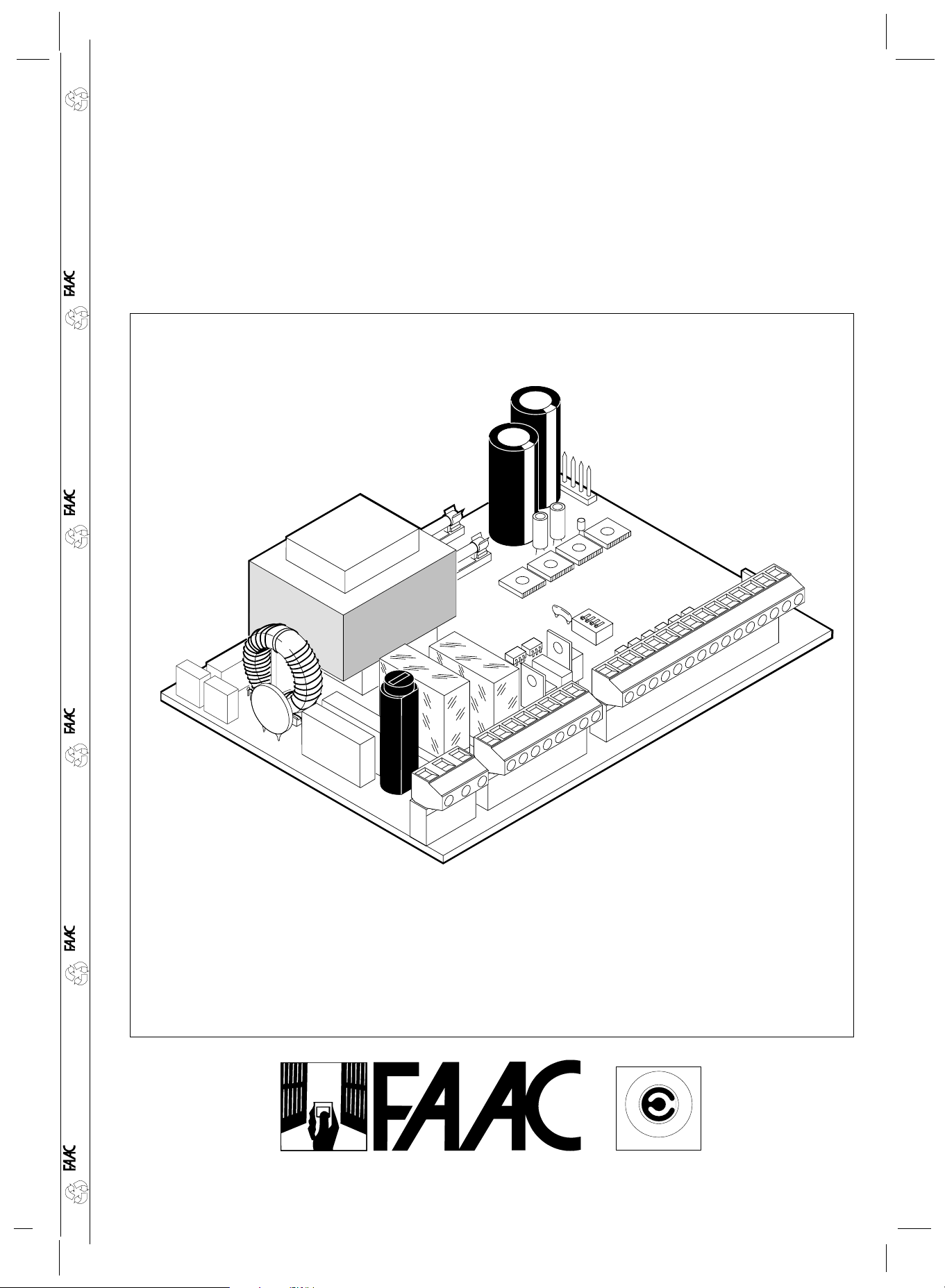
410 MPS
410 MPS
pour la nature
papier recyclé 100%
for nature
recycled paper 100%
per la natura
M
R
E
E
T
C
A
Z
I
E
N
D
UNI EN ISO 9001-085
A
C
I
F
A
I
T
C
R
E
A
T
carta riciclata 100%
Page 2

ENGLISH
IMPORTANT NO TICE FOR THE INSTALLER
GENERAL SAFETY REGULATIONS
1) WARNING! FAAC strongly recommends to follow these instructions literally for the safety of persons. Improper
installation or misuse of the product will cause very serious damages to persons.
2) Packaging material (plastic, polystyrene etc.) is a potential hazard and must be kept out of reach of children.
Read the instructions carefully before installing the product.
3)
4) Keep these instructions for future reference.
5) This product has been designed and manufactured only for the use stated in this manual. Any other use not expressly
set forth will affect the reliability of the product and/or could be source of hazard.
6) FAAC S.p.A. cannot be held responsible for any damage caused by improper use or different from the use for which
the automation system is destined to.
7) Do not use this device in areas subject to explosion: the presence of flammable gas or fumes is a serious hazard.
8) Mechanical constructive elements must comply with UNI8612, CEN pr EN 12604 and CEN pr EN 12605 standards.
Countries outside the EC shall follow the regulations above besides their national normative references in order to offer
the utmost safety.
9) FAAC cannot be held responsible for failure to observe technical standards in the construction of gates and doors,
or for any deformation of the gates which may occur during use.
10) Installation must comply with UNI8612, CEN pr EN 12453 and CEN pr EN 12635.
The degree of safety of the automation must be C+E.
11) Before carrying out any operations, turn off the system’s main switch.
12) An omnipower switch shall be provided for the installation with an opening distance of the contacts of 3 mm or more.
Alternatively, use a 6A thermomagnetic breaker with multi-pole switching.
13) Ensure that there is a differential switch up-line of the electrical system, with a trip threshold of 0.03A.
14) Check that the earthing plant is in perfect condition and connect it to the metallic parts. Also earth the yellow/green
wire of the operator.
15) The automation is fitted with an anti-crush safety system that is a torque control device. In any case, further safety
devices shall be installed.
16) The safety devices (e.g. photocells, safety edges, etc.) protect areas wherethere is a mechanical movement hazard,
e.g. crushing, entrapment and shearing.
17) Each installation must be fitted with at least one flashing light (e.g. FAAC LAMP, MINILAMP etc.) as well as a warning
plate suitably fixed to the gate, besides the safety devices as per point 16. above.
18) FAAC cannot be held responsible regarding safety and correct functioning of the automation in the event that parts
other than FAAC original parts are used.
19) Use only FAAC original spare parts for maintenance operations.
20) Do not carry out any modifications to automation components.
21) The installer must supply all information regarding manual operation of the system in the event of an emergency and
provide the end-user with the leaflet attached to the product.
22) Keep out of persons when the product is in operation.
23) Keep out of reach of children the remote radio controls and any control devices. The automation could be operated
unintentionally.
24) The end-user must avoid any attempt to repair or adjust the automation personally. These operations must be carried
out exclusively by qualified personnel.
25) What is not explicitly stated in these instructions is not permitted.
9
Page 3
ENGLISH
DESCRIPTION AND TECHNICAL SPECIFICATIONS
Table 1: 410 MPS Control unit technical specifications
Power supply 230 V(+6%-10%) - 50 Hz
Absorbed power 10 W
Max. motor load 800 W
Max. accessories load 0,25 A
Temperature range -20 °C +55 °C
Fuses N. 3 (see fig.1)
Operations logics Automatic / Semi-automatic / Safety /
Automatic timer/ Step-by-step semi-automatic
Opening/closing time Adjustable by trimmer (from 0-120 s)
Pause time Adjustable by trimmer (from 0-240 s)
Closing leaf delay time Adjustable by trimmer (from
Opening leaf delay time 2.5 s (Can be disabled through bridge)
Thrust force Adjustable by trimmer
Terminal block inputs Open/Stop/Opening safeties/
Closing safeties/ mains power +earth
Terminal block outputs Flashing light - motors
24 Vdc accessories power supply
Quick connector Decoding cards - RP 433 SL/DS
Microswitch programmable functions Operating logics
Closing safeties logics
J1
J2
0 -28 s)
J3
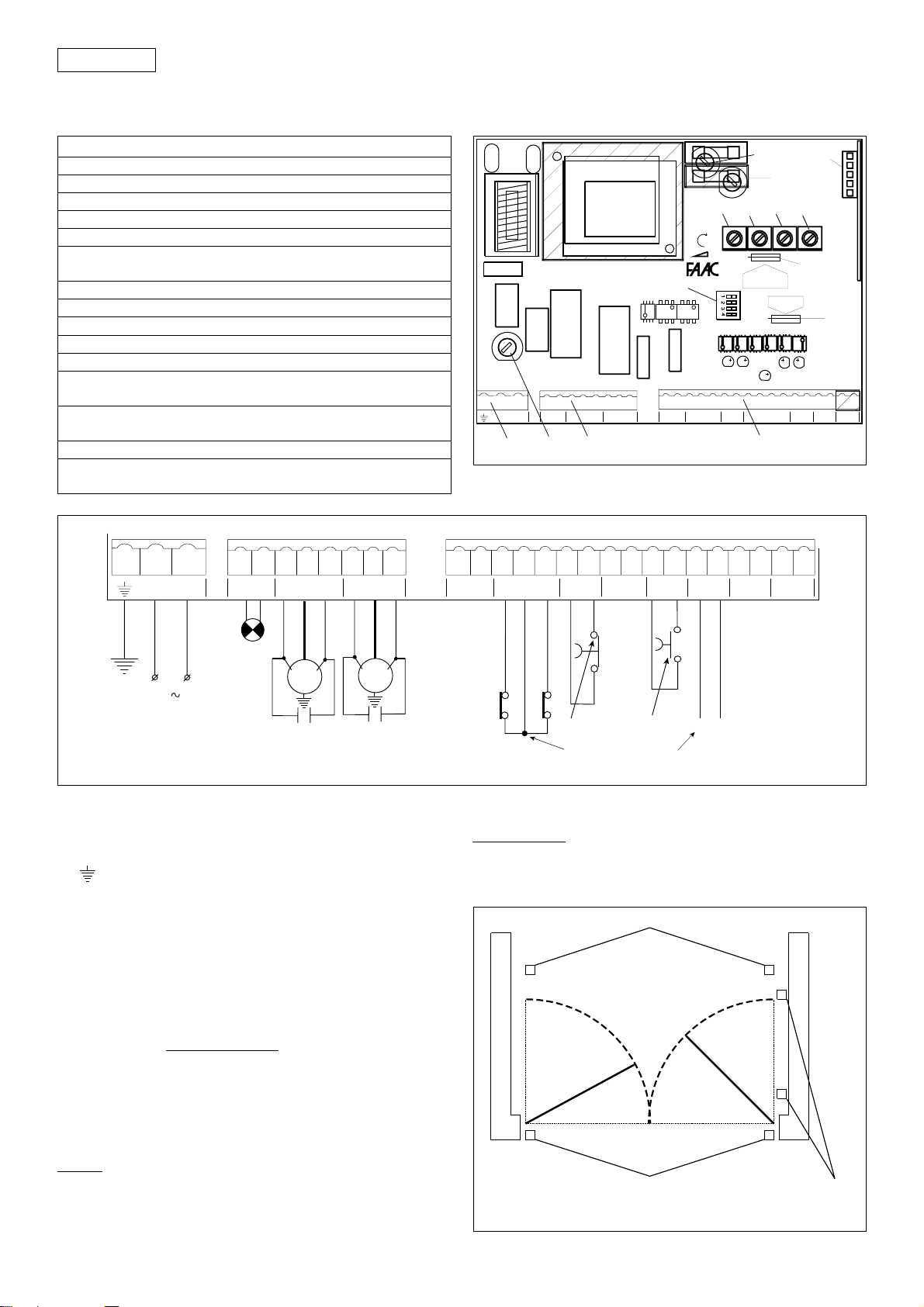
LAYOUT AND ELECTRICAL WIRING
i
F1
J2 J3J1
NL
b
j
a
e
DL4
f
F4
l
F2
g
OPENING
LEAF DELAY
DISABLE
DL2
DL5
c
k
FAILSAFE
ON-OFF
DL3
d
h
n
m
DL1
Fig. 1
1
2
N
230 V
3
L
50 Hz
4
5
OP COM CL CL COM OP
LAMP MOTOR 1 MOTOR 2
8
6
BLU
M1
C1
9
7
10
M2
C2
11
BLU
N.B.: The capacitors are provided with the operators.
Caution: Before touching the electronic unit (connections,
programming, maintenance) always switch off the power
supply.
a J1 terminal block (fig. 2)
: Earth connection
N. : power supply 230 V~ ( Neutre )
L. : power supply 230 V~ ( Phase)
N.B.: For correct operation the card must be connected to the
system’s earth. Install a suitable differential magneto-thermal
circuit-breaker upstream of the system.
b J2 terminal block (fig. 2)
LAMP.: flashing light output ( 230 V ~)
MOTOR 1 Open /Common/ Close: Motor 1 connection
Can be used in one-leaf application.
(
leaf closing delay)
MOTOR 2 Close /Common/ Open: Motor 2 connection
Not to be used in one-leaf application.
N.B. To check the operation of the equipment at the test
bench, a load must be connected on the MOTOR 1 input.
c J3 terminal block: low voltage (fig. 2) used to connect all
accessories (see table 2).
30 Vdc
– accessories power supply negative
+ accessories power supply positive (+ 30 Vdc)
12
13 14 15 16 17 18 19 20 21 22 23 24 25 26 27 28
+ —
OP — CL NC —
30 Vcc FSW STOP
B — A — + —
STOP
OPEN
TOT.
FSWTX W.LIGHT LOCK
FSW TX
+ —
For the safety and fail-safe devices, see the “Safety devices”
section.
Fig. 2
Warning: the max. accessory load is 250 mA. To calculate
absorption values, refer to table 2.
Safety devices
These are all devices (photocells, safety edges, magnetic
coils, etc.) with an N.C. (normally closed) contact which
activate if an obstacle obstructs the area protected by the
Opening, closing or opening/closing photocells
A
A
A
B
Closing photocells
B
Opening
photocells
Fig. 3
10
Page 4

ENGLISH
safety devices and stop the movement of the gate leaves
(fig. 3).
The 410 MPS card has an additional FAIL-SAFE device which
serves to check that the N.C. contact on the photocell
receiver is working efficiently before any operation(Can
be disabled through bridge Fig. 1 ref.13) .
N.B.: If the Opening safety devices are engaged when the
gate is closed, they prevent the leaves from opening.
If the Closing safety devices are engaged when the gate
is open, they prevent the leaves from closing.
OP. - Opening safety device contact (N.C.): in the A-S-E-EP-AD
logics, during the opening phase the safety devices stop
the movement of the gate leaves; when they are
disengaged the opening movement recommences. They
do not engage during closure.
N.B.: If opening safety devices are not connected, jumper
inputs OP and FSW TX (Fig. 4).
Application examples
The following are the commonly used connection arrangements (enable fail -safe):
No safety device connected One pneumatic edge connected as closing safety device and
15
14
OP — CL
FSW
16
+ —
FSWTX
2423
The purpose of the opening safety devices is to safeguard
the zone behind the gate leaves (A, fig. 3).
CL. - Closing safety device contact (N.C.): in the A-S-E-EP-AD
logics, during the closing phase the safety devices reverse
the direction of movement of the gate leaves, or they stop
the movement of the leaves then reverse direction when
they are disengaged (see microswitch SW4 settings). They
do not engage during the opening cycle.
N.B.: If closing safety devices are not connected, jumper
inputs OP and FSWTX (fig. 4).
The purpose of the closing safety devices is to safeguard
the zone in which the leaves move during the closing cycle
(B, fig. 3).
If the Fail-Safe function is not used, see cabling at page 4
for connections of photocells.
one connected as opening safety device
15
14
OP — CL
FSW
16
+ —
FSWTX
2423
Fig. 4
1 pair of closing photocells connected 1 pair of opening photocells connected
15
16
12
+ —
30Vcc
13
15
14
OP — CL
FSW
1
2
3
4
5
16
RX TX
+ —
FSWTX
1
2
2423
1 pair of opening photocells and 1 pair of closing
photocells connected
12
+ —
30Vcc
13
15
16
14
OP — CL
FSW
1
2
3
4
5
RX CL TX CL
+ —
FSWTX
1
2
2423
Fig. 6
1 pair of closing photocells and 1 pair of opening/closing
12
+ —
30Vcc
12
13
+ —
30Vcc
14
OP — CL
FSW
1
2
3
4
5
RX TX
photocells connected
15
16
14
13
OP — CL
FSW
1
2
3
4
5
RX CL TX CL
+ —
FSWTX
1
2
+ —
FSWTX
1
2
Fig. 5
2423
Fig. 7
2423
1
1
2
2
3
4
5
RX OPTX OP
1
2
RX OPTX OP
Fig. 8
Important: for further information on the operation of the safety devices, see table 3.
11
1
2
3
4
5
Fig. 9
Page 5

ENGLISH
Application examples
The following are the commonly used connection arrangements (disable fail -safe)
No safety device connected
One pneumatic edge connected as closing safety device and
one connected as opening safety device
15
14
OP — CL
FSW
16
+ —
FSWTX
2423
15
14
OP — CL
FSW
16
+ —
FSWTX
Fig. 4/A
1 pair of closing photocells connected 1 pair of opening photocells connected
12
+ —
30Vcc
13
15
16
14
OP — CL
FSW
1
2
3
4
5
RX TX
+ —
FSWTX
1
2
2423
12
+ —
30Vcc
OP — CL
FSW
1
2
3
4
5
15
16
14
13
RX TX
+ —
FSWTX
1
2
2423
Fig. 6/A
2423
Fig. 5/A
Fig. 7/A
Two pair of closure photocells connected
15
16
14
13
12
+ —
30Vcc
OP — CL
FSW
1
2
3
4
5
1
2
RX TX
TX
RX
+ —
FSWTX
1
2
5
4
3
2
1
1 pair of closing photocells and 1 pair of opening/closing
photocells connected
2423
12
+ —
30Vcc
13
15
14
OP — CL
FSW
1
2
3
4
5
16
RX TX
1
2
TX
Fig. 8/A
RX
+ —
FSWTX
1
2
5
4
3
2
1
2423
Fig. 9/A
12
Page 6

STOP
– Common ( - )
N.C. - STOP contact: all devices (such as pushbuttons)
which by opening a contact stop gate movement.
To install several safety stop devices, connect the N.C.
contacts in series.
N.B. If the STOP devices are not connected, jumper STOP
and - inputs.
– Common ( - )
A - TWO-LEAF OPENING (N.O.): all devices (pushbuttons ,
photocells, detectors, etc.) which assures opening/closing
of both leaves by closing a contact.
To install several control devices, connect the N.O. contacts
in parallel.
FSWTX
+ – Photocell transmitter power supply (FailSafe)
To use the Fail-Safe function, power supplies to the photocell
transmitters must be connected.
d J4 quick connector for decoder SL/DS - MINIDEC SL/DS - RP
433 SL/DS cards (figs. 10-11-12-13)
e TORQUE trimmer: thrust adjusting trimmer (anti-crushing
safety system).
f PAUSE trimmer: pause time adjusting trimmer (A/S AD/
logics).
Pause time is adjustable from 0 to 240 seconds.
g OP/CL trimmer: Opening/Closing time adjusting trimmer
Time is adjustable from 0 to 120 seconds.
h LEAF DELAY trimmer: closing leaf delay adjusting trimmer.
Leaf delay time is adjustable from 0 to 28 seconds.
N.B.:
1) If the opening/closing time is less than the set delay
time, the delayed leaf closes at the end of the closing
time.
2) In one-leaf application, set the leaf delay time to
minimum
i Programming microswitches
j Fuse F1 5x20 5 A/250 V rapid (motor power supply)
k Fuse F2 5x20 800 mA/250 V delayed (accessories power
supply)
l Fuse F4 5x20 250 mA/250 V delayed (transformer power
supply)
m Bridge to enable/disable the Fail-Safe (Fig. 14).
ENGLISH
PLUS
433 E
410 MPS
MINIDEC
SL/DS
Fig. 10
410 MPS
N.B. Use a dedicated decoder for other accessory types.
410 MPS
DECODER
SL
Fig. 11
n
Bridge to enable/disable the wing opening
delay(Fig. 14).
Table 2 - Current drawn by accessories
ACCESSORY CURRENT DRAWN
PLUS 40 SL 30 mA
PLUS 433 E 20 mA
MINIDEC SL / DS 6 mA
DECODER SL / DS 20 mA / 55 mA
RP 433 SL / DS 12 mA / 6 mA
DIGICARD 15 mA
METAL DIGIKEY 15 mA
FOTOSWITCH 90 mA
DETECTOR F4 / PS6 50 mA
PHOTOBEAM 50 mA
Fig. 12
410 MPS
Fig. 13
13
Page 7

ENGLISH
FAIL-SAFE
LEAF DELAY
Disable
Enable
DisableEnable
Fig. 14
1. PROGRAMMING THE MICROSWITCHES
Automation programming is carried out by the microswitches
(fig. 1 - ref. 9) as shown in the diagram below.
Fig. 15
1
23 4
OPERATING
LOGICS
A
S
E
EP
AD
SW1
OFF
ON
OFF
ON
ON
SW2 SW3
OFF
OFF
OFF OFF
OFF
ON
OFF
ON
ON
OFF
SAFETIES ON CLOSING
INVERTS MOVEMENT
IMMEDIATELY
STOPS AND INVERTS
MOVEMENT ON
DISENGAGEMENT
SW4
OFF
ON
1.1. OPERATION LOGICS
There are four operating logics available:
A: “AUTOMATIC ” E : “SEMI-AUTOMATIC”
S : “SAFETY” EP : “SEMI-AUTOMATIC STEP-BY-STEP”
AD: "AUTOMATIC TIMER"
Operation of the different logics is described in tables 3/a-b-c-de.
1.2. SAFETIES ON CLOSING
This function serves to select the operating mode for the closing
safeties:
- OFF: immediate reverse of movement during gate closure
- ON: movement is stopped during closing and reversed on
opening when the safety is disengaged.
2. START-UP
1) Program the 410 MPS electronic control unit according to
specific requirements as shown in fig. 15.
2) Check led status as shown in table.
LED functions
LEDS ON OFF
DL 1 (OPEN INPUT A) Command active Command not active
DL 3 (STOP) Command not active Command active
DL 4 (FTSW OPEN) Safeties disengaged Safeties engaged
DL 5 (FTSW CLOSE) Safeties disengaged Safeties engaged
N.B.: the bold text indicates led status with gate idle.
2.1. DIRECTION OF ROTATION
1) Switch off the power.
2) Manually move the gate to halfway.
3) Lock the operators.
4) Switch on the power.
5) Send an OPEN signal to input A (fig. 2) and check that the
leaf opens.
If the gate closes, invert the motor wires on the control unit
(brown and black wires).
2.2. OPERATION TIME ADJUSTMENT
Opening/closing times are set by the OP/CL trimmer on the
control unit (fig. 1 - ref.7).
To reduce operation time, adjust the trimmer anticlockwise
To increase operation time, adjust the trimmer clockwise.
Maximum operation time is 120 seconds.
For 90° opening the approximate opening/closing time is 18
seconds.
For optimal system efficiency set the opening/closing time so
that the electric motor remains activated for a few seconds
after the leaf has reached the mechanical travel stop.
2.3. CLOSING LEAF DELAY ADJUSTMENT
In the case of overlapping leaves, it is possible to delay closing
of the leaf driven by motor M1 (see fig. 2) to ensure correct
closure of the gate.
Set the delay by the LEAF DELAY trimmer on the 410 MPS control
unit (fig. 1 - ref. 8).
To reduce delay time, adjust the trimmer anticlockwise.
To increase delay time, adjust the trimmer clockwise.
Maximum delay time is 28 seconds. If the operation time is
shorter, the delay time is reduced automatically.
2.4. SETTING PAUSE TIME
When A, S or AD logics are selected, the leaf momentary stop
time can be set using the PAUSE trimmer (fig. 1 ref. 6).
Turn the trimmer clockwise to increase the time.
Turn the trimmer anticlockwise to reduce the time.
The maximum pause time is 240 sec.
2.5. ANTI-CRUSHING SYSTEM ADJUSTMENT
The 410 MPS control unit has been designed for use on both
electromechanical and hydraulic operators.
When the 410 MPS card is used on electromechanical operators,
the torque control device must be set by turning the TORQUE
trimmer (fig. 1 ref. 5).
To reduce torque, adjust the trimmer anticlockwise.
To increase torque, adjust the trimmer clockwise.
In any event, FAAC advises not to exceed a torque of 15 Kg
measured on the outer edge of the leaf.
To ensure precise torque adjustment use a linear dynamometer.
When the 410 MPS card is used on hydraulic operators, the
torque control device must be set to the maximum value by
turning the TORQUE trimmer clockwise.
This device is already present inside the operator hydraulic
circuit (BY-PASS valves).
14
Page 8

(*1) If residual pause time is less than 5 seconds on safety disengagement, the gate closes after 5 seconds.
N.B.: Effects of other active impulse inputs are shown in brackets
ENGLISH
No effect (OPEN inhibited)
OPENING/CLOSING SAFETIESCLOSING SAFETIESOPENING SAFETIES
No effect
PULSES
Stops closing and, when disengaged,
Freezes pause until disengagement (*1) (OPEN inhibited)
See paragraph 1.2
No effect
No effect (OPEN inhibited)
opens
continues to open
Stops opening and, when disengaged,
No effect (OPEN inhibited)
No effect
closes
No effect
PULSES
Stops opening and, when disengaged,
opens
No effect (OPEN inhibited)
OPENING/CLOSING SAFETIESCLOSING SAFETIESOPENING SAFETIES
No effect
Stops closing and, when disengaged,
Stops opening and, when disengaged,
Freezes pause until disengagement (*1) (OPEN inhibited)
No effect
No effect
See paragraph 1.2
No effect (OPEN inhibited)
Stops opening and, when disengaged,
continues to open
No effect (OPEN inhibited)
closes
No effect
opens
continues to open
No effect (OPEN inhibited)
OPENING/CLOSING SAFETIES
No effect
CLOSING SAFETIESOPENING SAFETIES
PULSES
Stops closing and, when disengaged,
Stops opening and, when disengaged,
No effect (OPEN inhibited)
No effect
See paragraph 1.2
No effect
closes
No effect (OPEN inhibited)
Stops opening and, when disengaged,
No effect (OPEN inhibited)
No effect
No effect (OPEN inhibited)
STOP
OPEN-A
Opens leaves and recloses after pause time
Stops
No effect (OPEN inhibited)Closes leaf/leaves
No effect
Reopens leaves immediately
Recloses leaves immediately
No effect (OPEN inhibited)
STOP
Stops
No effect (OPEN inhibited)
OPEN-A
Closes leaf/leaves
Recloses leaves immediately
Opens leaves and recloses after pause time
Recloses leaves immediately
Reopens leaves immediately
No effect (OPEN inhibited)
STOP
OPEN-A
Opens leaves
Stops
Stops
Recloses leaves immediately
Reopens leaves immediately
No effect (OPEN inhibited)
Closes leaf/leaves
GATE STATUS
LOGICS "A"
Table 3/a
CLOSED
OPEN on PAUSE
CLOSING
OPENING
STOPPED
GATE STATUS
LOGICS "S"
Table 3/b
CLOSED
OPEN on PAUSE
15
CLOSING
OPENING
STOPPED
GATE STATUS
LOGICS "E"
Table 3/c
OPEN
CLOSED
OPENING
CLOSING
STOPPED
Page 9

ENGLISH
opens
No effect (OPEN inhibited)
OPENING/CLOSING SAFETIESCLOSING SAFETIESOPENING SAFETIES
Stops closing and, when disengaged,
No effect (OPEN inhibited)
See paragraph 1.2
No effect
PULSES
continues to open
No effect (OPEN inhibited)
Stops opening and, when disengaged,
No effect
No effect
(if gate must close, inhibits OPEN)
closes
No effect
No effect (OPEN inhibited)
OPENING/CLOSING SAFETIESCLOSING SAFETIESOPENING SAFETIES
No effect
Freezes pause until disengagement (*1) (OPEN inhibited)
No effect
PULSES
(if the gate must open, inhibits OPEN)
Stops opening and, when disengaged,
opens
continues to open
Stops closing and, when disengaged,
Stops opening and, when disengaged,
No effect (OPEN inhibited)
No effect
See paragraph 1.2
closes
No effect
No effect (OPEN inhibited)
Stops opening and, when disengaged,
No effect (OPEN inhibited) No effect
STOP
OPEN-A
Opens leaves
Stops
No effect (OPEN inhibited)
Stops
Stops
Recloses leaf immediately
Inverts the direction
No effect (OPEN inhibited)
STOP
Stops
No effect (OPEN inhibited)Closes leaf/leaves
OPEN-A
Reopens leaves immediately
It controls the re-counting of the pause time
Opens leaves and recloses after pause time
If held, it remains in pause (timer function).
GATE STATUS
LOGICS "EP"
Table 3/d
OPEN
CLOSED
CLOSING
OPENING
STOPPED
GATE STATUS
LOGICS "AD"
Table 3/e
CLOSED
OPEN on PAUSE
CLOSING
OPENING
16
STOPPED
Page 10

Le descrizioni e le illustrazioni del presente manuale non sono impegnative. La FAAC si riserva il diritto,
lasciando inalterate le caratteristiche essenziali dell’apparecchiatura, di apportare in qualunque
momento e senza impegnarsi ad aggiornare la presente pubblicazione, le modifiche che essa ritiene
convenienti per miglioramenti tecnici o per qualsiasi altra esigenza di carattere costruttivo o
commerciale.
The descriptions and illustrations contained in the present manual are not binding. FAAC reserves the
right, whilst leaving the main features of the equipments unaltered, to undertake any modifications
it holds necessary for either technical or commercial reasons, at any time and without revising the
present publication.
Les descriptions et les illustrations du présent manuel sont fournies à titre indicatif. FAAC se réserve le
droit d’apporter à tout moment les modifications qu’elle jugera utiles sur ce produit tout en conservant
les caractéristiques essentielles, sans devoir pour autant mettre à jour cette publication.
Die Beschreibungen und Abbildungen in vorliegendem Handbuch sind unverbindlich. FAAC behält
sich das Recht vor, ohne die wesentlichen Eigenschaften dieses Gerätes zu verändern und ohne
Verbindlichkeiten in Bezug auf die Neufassung der vorliegenden Anleitungen, technisch bzw.
konstruktiv/kommerziell bedingte Verbesserungen vorzunehmen.
Las descripciones y las ilustraciones de este manual no comportan compromiso alguno. FAAC se
reserva el derecho, dejando inmutadas las características esenciales de los aparatos, de aportar, en
cualquier momento y sin comprometerse a poner al día la presente publicación, todas las
modificaciones que considere oportunas para el perfeccionamiento técnico o para cualquier otro
tipo de exigencia de carácter constructivo o comercial.
para la naturaleza
100% papel reciclado
ist umweltfreundlich
100% Altpapier
FAAC per la natura
• La presente istruzione è realizzata al 100% in carta riciclata.
• Non disperdete nell'ambiente gli imballaggi dei componenti dell'automazione bensì selezionate
i vari materiali (es. cartone, polistirolo) secondo prescrizioni locali per lo smaltimento rifiuti e le
norme vigenti.
FAAC for the environment
• The present manual is produced in 100% recycled paper
• Respect the environment. Dispose of each type of product packaging material (card, polystyrene)
in accordance with the provisions for waste disposal as specified in the country of installation.
FAAC der Umwelt zuliebe
• Vorliegende Anleitungen sind auf 100% Altpapier gedruckt.
• Verpackungsstoffe der Antriebskomponenten (z.B. Pappe, Styropor) nach den einschlägigen
Normen der Abfallwirtschaft sortenrein sammeln.
FAAC écologique
• La présente notice a été réalisée 100% avec du papier recyclé.
• Ne pas jeter dans la nature les emballages des composants de l’automatisme, mais sélectionner
les différents matériaux (ex.: carton, polystyrène) selon la législation locale pour l’élimination des
déchets et les normes en vigueur.
FAAC por la naturaleza.
• El presente manual de instrucciones se ha realizado, al 100%, en papel reciclado.
• Los materiales utilizados para el embalaje de las distintas partes del sistema automático (cartón,
poliestireno) no deben tirarse al medio ambiente, sino seleccionarse conforme a las prescripciones
locales y las normas vigentes para el desecho de residuos sólidos.
FAAC S.p.A.
Via Benini, 1
40069 Zola Predosa (BO) - ITALIA
Tel.: 051/6172411 - Tlx.: 521087
Fax: 051/758518
pour la nature
papier recyclé 100%
for nature
recycled paper 100%
Timbro del Rivenditore:/Distributor’s Stamp:/Timbre de l’Agent:/ Fachhändlerstempel:/Sello del Revendedor:
per la natura
732259 - Rev. D - 11000 - 697 - M
carta riciclata 100%
 Loading...