


VSC 900
VSC 900/900D
Video Scan Converter
68-635-01 Rev. D
04 05

Precautions
Safety Instructions • English
This symbol is intended to alert the user of important operating and maintenance
(servicing) instructions in the literature provided with the equipment.
This symbol is intended to alert the user of the presence of uninsulated dangerous
voltage within the product's enclosure that may present a risk of electric shock.
Caution
Read Instructions • Read and understand all safety and operating instructions before using the
equipment.
Retain Instructions • The safety instructions should be kept for future reference.
Follow Warnings • Follow all warnings and instructions marked on the equipment or in the user
information.
Avoid Attachments • Do not use tools or attachments that are not recommended by the equipment
manufacturer because they may be hazardous.
Consignes de Sécurité • Français
Ce symbole sert à avertir l’utilisateur que la documentation fournie avec le
matériel contient des instructions importantes concernant l’exploitation et la
maintenance (réparation).
Ce symbole sert à avertir l’utilisateur de la présence dans le boîtier de l’appareil
de tensions dangereuses non isolées posant des risques d’électrocution.
Attention
Lire les instructions• Prendre connaissance de toutes les consignes de sécurité et d’exploitation avant
d’utiliser le matériel.
Conserver les instructions• Ranger les consignes de sécurité afin de pouvoir les consulter à l’avenir.
Respecter les avertissements • Observer tous les avertissements et consignes marqués sur le matériel ou
présentés dans la documentation utilisateur.
Eviter les pièces de fixation • Ne pas utiliser de pièces de fixation ni d’outils non recommandés par le
fabricant du matériel car cela risquerait de poser certains dangers.
Sicherheitsanleitungen • Deutsch
Dieses Symbol soll dem Benutzer in der im Lieferumfang enthaltenen
Dokumentation besonders wichtige Hinweise zur Bedienung und Wartung
(Instandhaltung) geben.
Dieses Symbol soll den Benutzer darauf aufmerksam machen, daß im Inneren des
Gehäuses dieses Produktes gefährliche Spannungen, die nicht isoliert sind und
die einen elektrischen Schock verursachen können, herrschen.
Achtung
Lesen der Anleitungen • Bevor Sie das Gerät zum ersten Mal verwenden, sollten Sie alle Sicherheits-und
Bedienungsanleitungen genau durchlesen und verstehen.
Aufbewahren der Anleitungen • Die Hinweise zur elektrischen Sicherheit des Produktes sollten Sie
aufbewahren, damit Sie im Bedarfsfall darauf zurückgreifen können.
Befolgen der Warnhinweise • Befolgen Sie alle Warnhinweise und Anleitungen auf dem Gerät oder in
der Benutzerdokumentation.
Keine Zusatzgeräte • Verwenden Sie keine Werkzeuge oder Zusatzgeräte, die nicht ausdrücklich vom
Hersteller empfohlen wurden, da diese eine Gefahrenquelle darstellen können.
Warning
Power sources • This equipment should be operated only from the power source indicated on
the product. This equipment is intended to be used with a main power system with a
grounded (neutral) conductor. The third (grounding) pin is a safety feature, do not attempt
to bypass or disable it.
Power disconnection • To remove power from the equipment safely, remove all power cords
from the rear of the equipment, or the desktop power module (if detachable), or from the
power source receptacle (wall plug).
Power cord protection • Power cords should be routed so that they are not likely to be stepped
on or pinched by items placed upon or against them.
Servicing • Refer all servicing to qualified service personnel. There are no user-serviceable parts
inside. To prevent the risk of shock, do not attempt to service this equipment yourself because
opening or removing covers may expose you to dangerous voltage or other hazards.
Slots and openings • If the equipment has slots or holes in the enclosure, these are provided to
prevent overheating of sensitive components inside. These openings must never be blocked by
other objects.
Lithium battery • There is a danger of explosion if battery is incorrectly replaced. Replace it only
with the same or equivalent type recommended by the manufacturer. Dispose of used batteries
according to the manufacturer's instructions.
Avertissement
Alimentations• Ne faire fonctionner ce matériel qu’avec la source d’alimentation indiquée sur
l’appareil. Ce matériel doit être utilisé avec une alimentation principale comportant un fil de
terre (neutre). Le troisième contact (de mise à la terre) constitue un dispositif de sécurité :
n’essayez pas de la contourner ni de la désactiver.
Déconnexion de l’alimentation• Pour mettre le matériel hors tension sans danger, déconnectez tous
les cordons d’alimentation de l’arrière de l’appareil ou du module d’alimentation de bureau (s’il
est amovible) ou encore de la prise secteur.
Protection du cordon d’alimentation • Acheminer les cordons d’alimentation de manière à ce que
personne ne risque de marcher dessus et à ce qu’ils ne soient pas écrasés ou pincés par des
objets.
Réparation-maintenance • Faire exécuter toutes les interventions de réparation-maintenance par un
technicien qualifié. Aucun des éléments internes ne peut être réparé par l’utilisateur. Afin
d’éviter tout danger d’électrocution, l’utilisateur ne doit pas essayer de procéder lui-même à ces
opérations car l’ouverture ou le retrait des couvercles risquent de l’exposer à de hautes tensions
et autres dangers.
Fentes et orifices • Si le boîtier de l’appareil comporte des fentes ou des orifices, ceux-ci servent à
empêcher les composants internes sensibles de surchauffer. Ces ouvertures ne doivent jamais
être bloquées par des objets.
Lithium Batterie • Il a danger d'explosion s'll y a remplacment incorrect de la batterie. Remplacer
uniquement avec une batterie du meme type ou d'un ype equivalent recommande par le
constructeur. Mettre au reut les batteries usagees conformement aux instructions du fabricant.
Vorsicht
Stromquellen • Dieses Gerät sollte nur über die auf dem Produkt angegebene Stromquelle betrieben
werden. Dieses Gerät wurde für eine Verwendung mit einer Hauptstromleitung mit einem
geerdeten (neutralen) Leiter konzipiert. Der dritte Kontakt ist für einen Erdanschluß, und stellt
eine Sicherheitsfunktion dar. Diese sollte nicht umgangen oder außer Betrieb gesetzt werden.
Stromunterbrechung • Um das Gerät auf sichere Weise vom Netz zu trennen, sollten Sie alle
Netzkabel aus der Rückseite des Gerätes, aus der externen Stomversorgung (falls dies möglich
ist) oder aus der Wandsteckdose ziehen.
Schutz des Netzkabels • Netzkabel sollten stets so verlegt werden, daß sie nicht im Weg liegen und
niemand darauf treten kann oder Objekte darauf- oder unmittelbar dagegengestellt werden
können.
Wartung • Alle Wartungsmaßnahmen sollten nur von qualifiziertem Servicepersonal durchgeführt
werden. Die internen Komponenten des Gerätes sind wartungsfrei. Zur Vermeidung eines
elektrischen Schocks versuchen Sie in keinem Fall, dieses Gerät selbst öffnen, da beim Entfernen
der Abdeckungen die Gefahr eines elektrischen Schlags und/oder andere Gefahren bestehen.
Schlitze und Öffnungen • Wenn das Gerät Schlitze oder Löcher im Gehäuse aufweist, dienen diese
zur Vermeidung einer Überhitzung der empfindlichen Teile im Inneren. Diese Öffnungen dürfen
niemals von anderen Objekten blockiert werden.
Litium-Batterie • Explosionsgefahr, falls die Batterie nicht richtig ersetzt wird. Ersetzen Sie
verbrauchte Batterien nur durch den gleichen oder einen vergleichbaren Batterietyp, der auch
vom Hersteller empfohlen wird. Entsorgen Sie verbrauchte Batterien bitte gemäß den
Herstelleranweisungen.
Instrucciones de seguridad • Español
Este símbolo se utiliza para advertir al usuario sobre instrucciones importantes
de operación y mantenimiento (o cambio de partes) que se desean destacar en el
contenido de la documentación suministrada con los equipos.
Este símbolo se utiliza para advertir al usuario sobre la presencia de elementos
con voltaje peligroso sin protección aislante, que puedan encontrarse dentro de
la caja o alojamiento del producto, y que puedan representar riesgo de electrocución.
Precaucion
Leer las instrucciones • Leer y analizar todas las instrucciones de operación y seguridad, antes de usar
el equipo.
Conservar las instrucciones • Conservar las instrucciones de seguridad para futura consulta.
Obedecer las advertencias • Todas las advertencias e instrucciones marcadas en el equipo o en la
documentación del usuario, deben ser obedecidas.
Evitar el uso de accesorios • No usar herramientas o accesorios que no sean especificamente
recomendados por el fabricante, ya que podrian implicar riesgos.
Advertencia
Alimentación eléctrica • Este equipo debe conectarse únicamente a la fuente/tipo de alimentación
eléctrica indicada en el mismo. La alimentación eléctrica de este equipo debe provenir de un
sistema de distribución general con conductor neutro a tierra. La tercera pata (puesta a tierra) es
una medida de seguridad, no puentearia ni eliminaria.
Desconexión de alimentación eléctrica • Para desconectar con seguridad la acometida de
alimentación eléctrica al equipo, desenchufar todos los cables de alimentación en el panel trasero
del equipo, o desenchufar el módulo de alimentación (si fuera independiente), o desenchufar el
cable del receptáculo de la pared.
Protección del cables de alimentación • Los cables de alimentación eléctrica se deben instalar en
lugares donde no sean pisados ni apretados por objetos que se puedan apoyar sobre ellos.
Reparaciones/mantenimiento • Solicitar siempre los servicios técnicos de personal calificado. En el
interior no hay partes a las que el usuario deba acceder. Para evitar riesgo de electrocución, no
intentar personalmente la reparación/mantenimiento de este equipo, ya que al abrir o extraer las
tapas puede quedar expuesto a voltajes peligrosos u otros riesgos.
Ranuras y aberturas • Si el equipo posee ranuras o orificios en su caja/alojamiento, es para evitar el
sobrecalientamiento de componentes internos sensibles. Estas aberturas nunca se deben obstruir
con otros objetos.
Batería de litio • Existe riesgo de explosión si esta batería se coloca en la posición incorrecta. Cambiar
esta batería únicamente con el mismo tipo (o su equivalente) recomendado por el fabricante.
Desachar las baterías usadas siguiendo las instrucciones del fabricante.
Quick Start — VSC 900/900D
RS-232 Control
Betacam
Tape Deck
Videoconferencing
System
VCR
Monitor
Hi-Resolution Workstations
Video Editor
50/60 Hz
100-240V 0
.3A
R
/R
-Y
R
/R
-Y
I
N
P
U
T
S
O
U
T
P
U
T
S
G
/Y
2
R
G
B
/R
-Y
, B
-Y
, Y
R
G
B
1
G
-Y
B
/B
-Y
B
/B
-Y
H
/H
V
H
/H
V
V
V
V
ID
E
O
S
-
V
I
D
E
O
D
1
R
/R
-Y
G
/Y
B
/B
-Y
H
/H
-Y
R
S
-23
2
/4
2
2
G
E
N
L
O
C
K
V
IN
O
U
T
Extron
VSC 900D
Computer-to-Video
Scan Converter
Composite
S-video
Component
SDI
or
Extron
VSC Remote
Infrared Remote
P
O
W
E
R
1
2
V
.
2
A
M
A
X
L
R
4
3
2
1
6
5
PAL
NTSC
BLACKBURST
B
L
A
C
K
B
U
R
S
T
C
O
L
O
R
B
A
R
S
-10
+4
1 2 3
ON
1
K
H
Z
A
U
D
IO
B
B
G
6
A
B
L
A
C
K
B
U
R
S
T
A
N
D
A
U
D
I
O
G
E
N
E
R
A
T
O
R
Extron
BBG 6 A
Black Burst/
Audio Generator
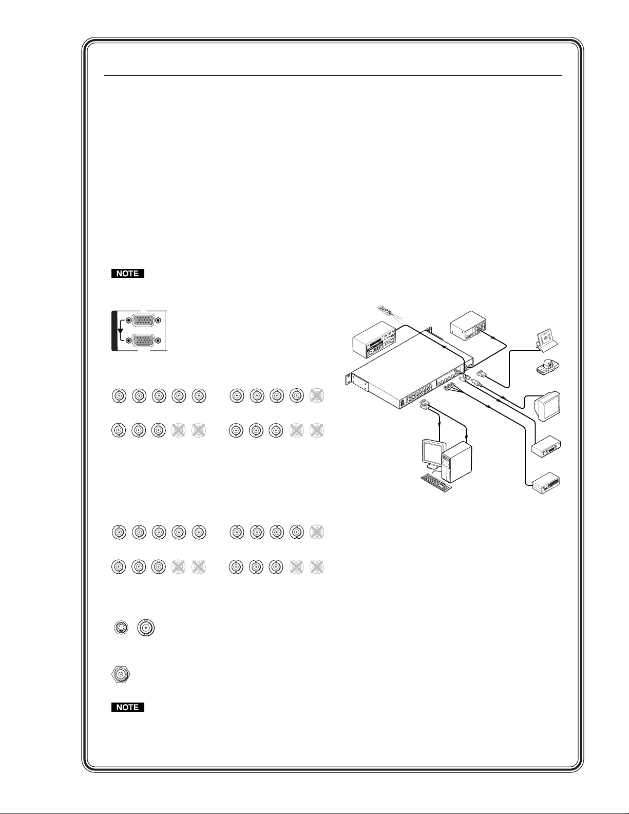
Installation
Step 1
Turn off power to the scan converter and any input
and output devices, and remove power cords from
them.
Step 2
Install the four rubber feet on the bottom of the
VSC, or mount the VSC in a rack.
Step 3
Rear panel video inputs
Attach an input device to the scan converter.
Buffered loop-trhough connectors allow for
local monitor output.
Input VGA connector
1
I
N
P
U
T
S
RGB
Step 5
Plug the scan converter, and input and output
devices into a grounded AC source, and turn on
the input and output devices.
Step 6
Use the LCD menu screens (see the next page) or
RS-232 programming to configure the VSC. See
chapter two for installation and operation
procedures, and see chapter three for
programming information.
Application Example
Input BNC connectors
R
/R-Y
R
/R-Y
B
G
/Y
/B-Y
RGBHV input
B
G
/Y
/B-Y
RGsB input
V
H
/HV
V
H
/HV
R
/R-Y
R
/R-Y
Component video input
(R-Y, Y, B-Y)
Step 4
Rear panel video outputs
Attach output devices to the VSC scan converter.
Output BNC connectors
/R-Y
/Y
R
G
RGBHV output
/R-Y
R
/Y
G
RGsB output
Output S-video and composite video connectors
VIDEO
S-VIDEO
Output SDI connector for SDI output
SDI
/HV
B
/B-Y
V
H
/Y
R
/R-Y
G
RGBS output
/B-Y
B
V
H
/HV
/R-Y
R
G
/Y
Component video output
(R-Y, Y, B-Y)
The scan converter will simultaneously
output RGB or component video, S-video,
composite video, and SDI (VSC 900D).
B
G
/Y
/B-Y
RGBS input
G
B
/Y
/B-Y
/B-Y
B
/B-Y
B
H
V
/HV
H
V
/HV
V
/HV
H
H
/HV
V
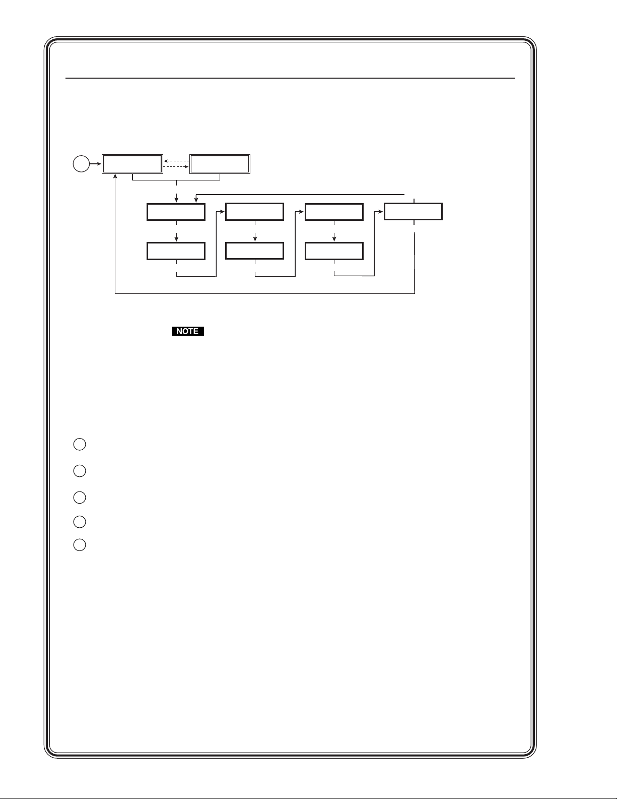
Quick Start — VSC 900/900D, cont’d
VSC 900/900D Main Menu System
Main menu
Power
on
Extron VSC 900
Scan Converter
2 sec.
2 sec.
MENU
Press NEXT to
Auto Image
MENU
Output
Config
MENU
Horiz. 56.19 KHz
Vert. 49.95 Hz
Filters
MENU
Size/Zoom
MENU
Advanced
MENU
Genlock
MENU
MENU
Exit
Menu
NEXT
See chapter two for detailed explanations of the menu system.
Image Optimization
The following steps should be folllowed in order to optimize image display. See chapter two, Installation and
Operation, for detailed adjustment features and instructions.
Use Auto Image.
1
Size and Center the image, if necessary.
2
Adjust the Horizontal filter.
3
Adjust the Vertical filter (flicker).
4
Adjust the Encoder.
5

Chapter 1 • Introduction ...................................................................................................... 1-1
About this Manual ............................................................................................................ 1-2
About the VSC 900/900D ................................................................................................ 1-2
Features................................................................................................................................... 1-2
Chapter 2 • Installation and Operation...................................................................... 2-1
Application Example ........................................................................................................ 2-2
Mounting the VSC ............................................................................................................. 2-2
Tabletop/desktop placement ........................................................................................... 2-2
Rack mounting .................................................................................................................. 2-3
Rear Panel Connectors and Cabling ........................................................................ 2-4
Genlock and Vertical Interval Switching.............................................................. 2-6
Genlock setup .................................................................................................................... 2-6
Oscilloscope displays ........................................................................................................ 2-7
Front Panel Features ........................................................................................................ 2-9
Menus, Configuration, and Adjustments .......................................................... 2-10
Moving through menus by using front panel controls ............................................. 2-10
Menu overview ............................................................................................................... 2-10
Auto Imaging menu (Auto Image) ............................................................................... 2-11
Output Configuration menu (Output Config) ............................................................ 2-12
Output signal submenu (Output) ..................................................................................... 2-12
Video standard submenu (Standard) ............................................................................... 2-12
Set NTSC pedestal submenu (Setup NTSC) ...................................................................... 2-12
Set PAL pedestal submenu (Setup PAL) ........................................................................... 2-13
No input signal display type submenu ..............................................................................2-13
Filters menu (Filters) ....................................................................................................... 2-13
Flicker filter adjustment submenu (Flicker) .....................................................................2-13
Horizontal filter adjustment submenu (H Filter)............................................................. 2-13
Encoder adjustment submenu (Encoder) .........................................................................2-13
Size and Zoom menu (Size/Zoom) ................................................................................ 2-14
Size adjustment submenu (Size) ....................................................................................... 2-14
Zoom in/out adjustment submenu (Zoom) ...................................................................... 2-14
Advanced functions menu (Advanced) ........................................................................ 2-14
Test pattern submenu....................................................................................................... 2-15
Input type submenu .......................................................................................................... 2-15
Input chroma attenuation submenu (Atten.) .................................................................. 2-15
Genlock menu (Genlock) ................................................................................................ 2-15
Horizontal and Subcarrier Phase submenu (H Phase Sub) ..............................................2-15
Exit menu (Exit Menu).................................................................................................... 2-15
Additional Functions ..................................................................................................... 2-16
Center function ............................................................................................................... 2-16
Freeze mode .................................................................................................................... 2-16
Unit reset function ......................................................................................................... 2-17
Input reset function ....................................................................................................... 2-17
Executive mode............................................................................................................... 2-18
VSC 900/900D • Table of Contents
i

Table of Contents, cont’d
Presets ................................................................................................................................... 2-19
Troubleshooting ............................................................................................................... 2-19
VSC Infrared Remote Control ................................................................................... 2-21
Chapter 3 • Serial Communication ................................................................................ 3-1
RS-232 Programmer’s Guide ........................................................................................ 3-2
Host-to-scan converter communications ........................................................................ 3-2
Video scan converter-initiated messages .......................................................................... 3-2
Error responses ................................................................................................................... 3-2
Using the command/response tables ................................................................................. 3-3
Control Software for Windows ................................................................................. 3-7
Installing the software ..................................................................................................... 3-7
Using the control program .............................................................................................. 3-7
Using the help program ................................................................................................... 3-8
Firmware Upgrade through the Extron Website ............................................. 3-9
Downloading the latest firmware to the PC ................................................................. 3-9
Uploading the firmware from the PC to the VSC 900/900D ........................................ 3-9
Appendix A • Reference Information ......................................................................... A-1
Specifications ..................................................................................................................... A-2
Included Parts ..................................................................................................................... A-4
Accessories .......................................................................................................................... A-4
Firmware Upgrade Chip Installation ..................................................................... A-5
Serial Digital Interface (SDI) Output Card Installation .............................. A-7
All trademarks mentioned in this manual are the properties of their respective owners.
ii VSC 900/900D • Table of Contents
68-635-01 Rev. D
04 05

VSC 900/900D
Chapter One
1
Introduction
About this Manual
About the VSC 900/900D
Features

Introduction
About this Manual
This manual discusses how to install, configure, and operate the Extron
VSC 900/900D video scan converter and how to operate the VSC infrared remote
control (part #70-206-01).
Throughout this manual the terms “VSC”, “video scan converter”, and “scan
converter” are used interchangeably to refer to the same product.
About the VSC 900/900D
The VSC 900/900D is a two-input, high resolution computer-to-video scan
converter that accepts resolutions up to 1600 x 1200 and simultaneously outputs
NTSC/PAL composite video, S-video, component or RGB video, and SDI
component video (VSC 900D only).
The VSC 900/900D can be genlocked to an external blackburst signal for use in a
production or broadcast environment. The scan converter may also be remotely
controlled via RS-232/RS-422 Simple Instruction Set (SIS
the optional VSC IR remote control.
Features
Autoscanning — Automatically recognizes and converts the incoming computer
Buffered loop-throughs — Five rear-panel BNC connectors and one VGA-type
Three simultaneous outputs — NTSC or PAL video is output as RGBHV, RGBS,
Input memory presets — Up to 16 user presets, 60 factory presets, and eight
Freeze button — The input of the VSC can be frozen by pressing this button.
Auto-Image
Vertical (flicker) filtering — Four levels of vertical (flicker) filtering provide line
RS-232/RS-422 remote control — An RS-232/RS-422 control port utilizes
Internal test pattern generator — The VSC 900/900D offers four test patterns for
Executive mode — Enables the user to lock out all front panel functions except
™
) commands or with
image, up to 1600 x 1200 resolution, 100 kHz horizontal, and 120 Hz
vertical scan rates.
15-pin HD connector provide connections for RGB or component video
(R-Y, Y, B-Y) buffered loop-through. Both outputs (the BNCs and the 15pin HD connector) are active at all times for simultaneous output.
RGsB, or component video, S-video, and composite video. An optional SDI
output is available (VSC 900D only) for inclusion of digital video devices.
zoom presets, accessible via the front panel, RS-232, or the included IR
remote. Each memory location stores filter, size, centering, and/or zoom
settings for a source that can be instantaneously recalled during a
presentation.
This feature allows the scan converter to capture a frame of video to
display for an extended period of time, even after the source has been
removed.
™
setup — This feature allows for automatic adjustment of sizing,
centering, and filtering to optimize the output image.
averaging so that vertical detail is maintained during the scan conversion
process and picture flicker is eliminated.
™
Extron’s Simple Instruction Set (SIS
quick and easy monitor setup: color bars, 32 x 32 crosshatch, 4 x 4
crosshatch, and grayscale.
for centering controls; all other functions functions remain active through
the RS-232/RS-422 port.
) of basic ASCII commands.
VSC 900/900D • Introduction1-2

VSC 900/900D
Chapter Two
Installation and Operation
2
Application Example
Mounting the VSC
Rear Panel Connectors and Cabling
Genlock and Vertical Interval Switching
Front Panel Features
Menus, Configuration, and Adjustments
Additional Functions
Presets
Troubleshooting
VSC Infrared Remote Control
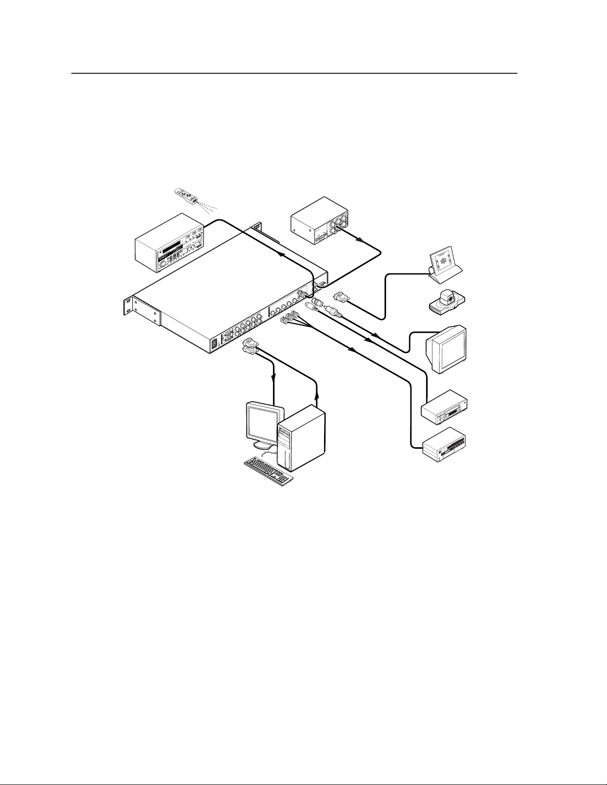
Installation and Operation
Application Example
The illustration below is one example of setting up the VSC 900D. The
VSC 900 setup does not include an SDI output.
Extron
VSC Remote
Infrared Remote
Video Editor
SDI
BBG 6 A
BLACKBURST AND AUDIO
GENERATOR
POWER
V
2
1
A
.2
Extron
BBG 6 A
T
S
R
U
B
K
C
A
5
L
B
Black Burst/
3
6
1
Audio Generator
4
BLACKBURST
NTSC
2
+4
S
N
R
Z
O
A
H
B
R
K
1
O
IO
L
D
R
O
U
C
A
1 2 3
L
PAL
X
-10
A
M
1
I
A
N
.3
0
P
V
0
4
-2
0
0
U
1
B
T
G
R
S
z
H
0
/6
0
Extron
5
VSC 900D
Computer-to-Video
Scan Converter
Hi-Resolution Workstations
Mounting the VSC
Select tabletop placement or rack mounting. Follow the appropriate installation
instructions on the following pages.
or
RS-232 Control
Videoconferencing
System
Monitor
Composite
VCR
S-video
IN
-232
S
R
/422
G
T
U
E
O
N
L
O
1
D
C
O
K
E
ID
V
O
E
ID
-V
S
V
-Y
/H
H
-Y
/B
B
/Y
G
O
U
-Y
/R
R
T
P
V
U
T
S
H
V
/H
V
B
2
-Y
/B
H
V
/H
G
/Y
B
-Y
/B
R
-Y
/R
-Y
G
, Y
-Y
, B
-Y
/R
R
B
-Y
G
/R
R
Betacam
Tape Deck
Component
Tabletop/desktop placement
For tabletop or desktop placement only, install the self-adhesive rubber feet/pads
(provided) onto the four corners of the bottom of the enclosure.
VSC 900/900D • Installation and Operation2-2
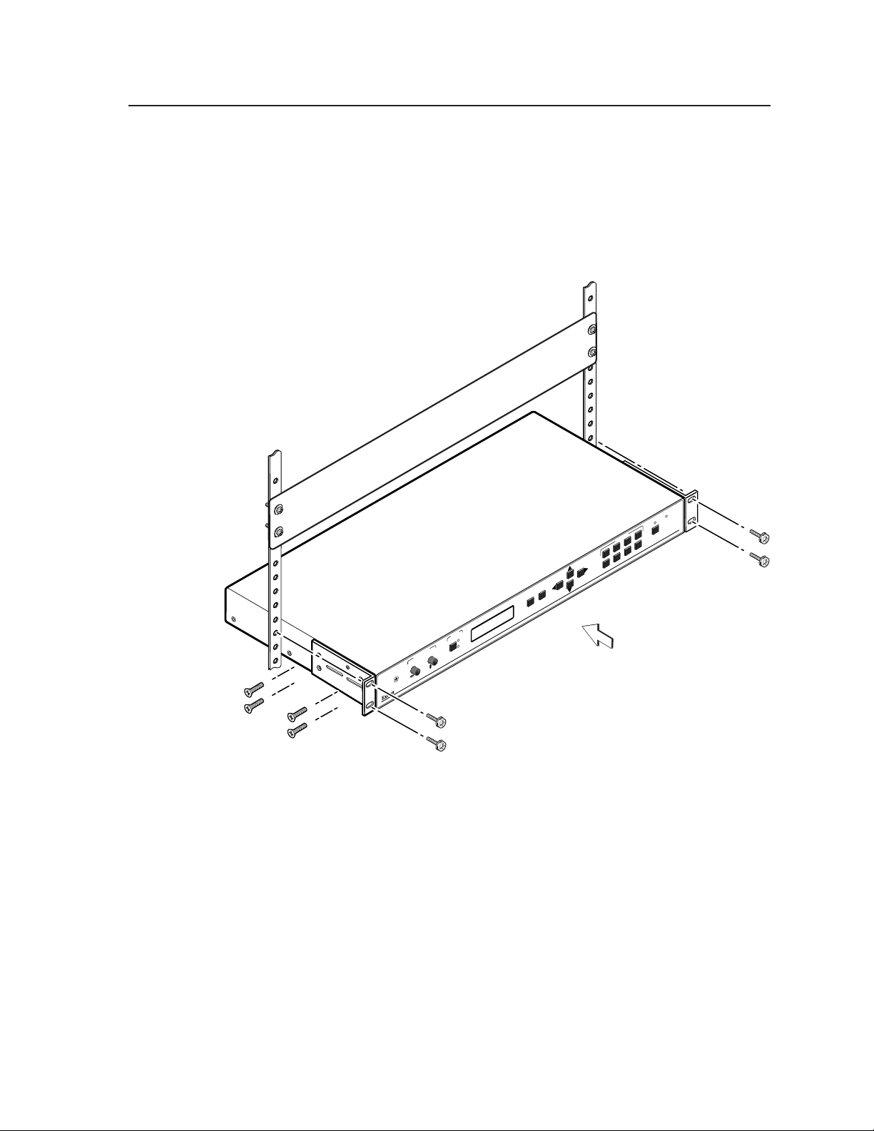
Rack mounting
1. If feet were installed on the bottom of the VSC, remove them.
2. Attach the provided rack mounting brackets (70-077-03) to the
VSC 900/900D with machine screws, as shown below.
3. Fasten the VSC to the rack using the supplied machine screws.
PRESETS
234
COM
1
5 678
PUTER TO
GENLOCK
FREEZE/
RESET
VIDEO SCAN CONVERTER
VSC 900
(4) #8 Screws each side
Figure 2-1 — Rack mounting the VSC 900/900D
NEXT
MENU
INPUT
1
CENTER/PAN
IR
2
2-3VSC 900/900D • Installation and Operation
Installation and Operation
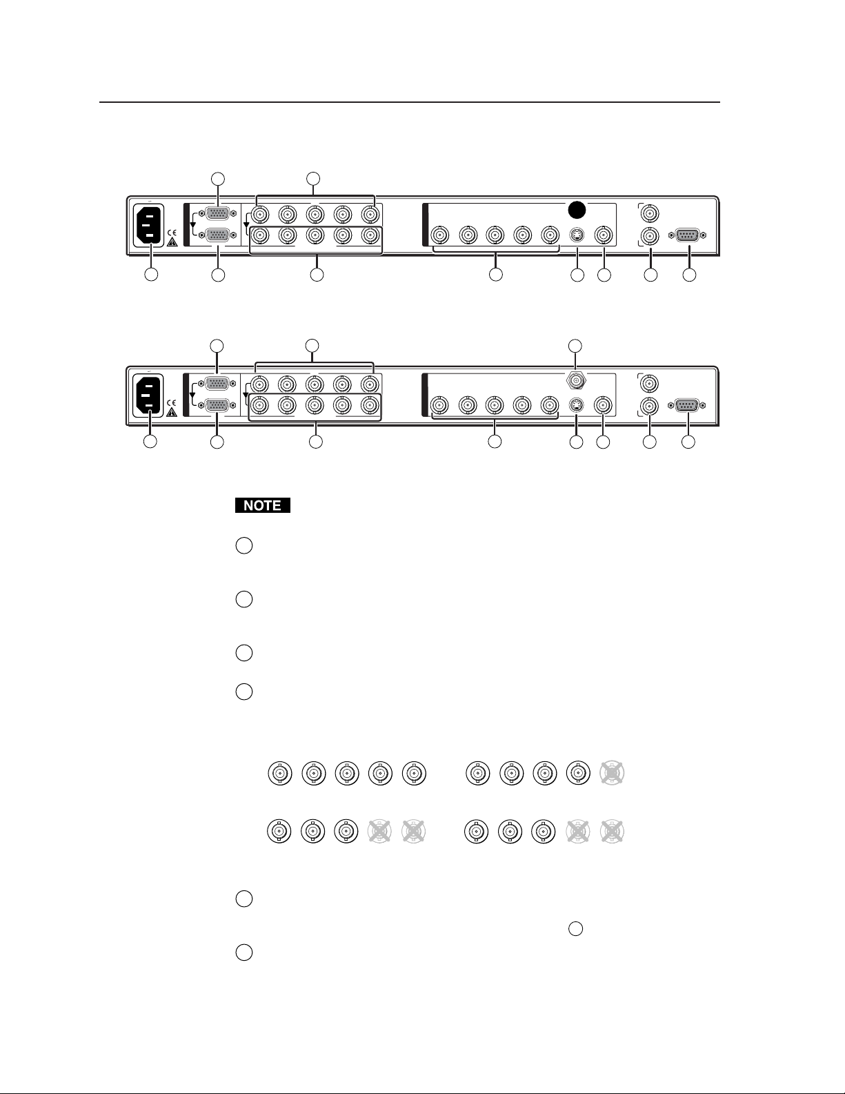
Rear Panel Connectors and Cabling
100-240V 0.3A
50/60 Hz
100-240V 0.3A
50/60 Hz
2
1
I
N
P
U
T
S
RGB
1
3 7a
R
/R-Y
R
/R-Y
4
2
G
/Y
G
/Y
RGB/R-Y, Y, B-Y
5
B
H
/B-Y
B
/B-Y
V
/HV
H
V
/HV
O
U
T
R/R-Y
P
U
T
S
G/Y
B/B-Y H/H-Y
6
V
S-VIDEO
VIDEO
8
IN
G
E
N
L
OUT
O
C
K
9 10
RS-232
/422
Figure 2-2 — VSC 900 rear panel connectors
2 7b
1
I
N
P
U
T
S
RGB
1
3 7a
R
/R-Y
R
/R-Y
4
2
G
/Y
G
/Y
RGB/R-Y, Y, B-Y
5
B
H
/B-Y
B
/B-Y
V
/HV
H
V
/HV
O
U
T
R/R-Y
P
U
T
S
G/Y
B/B-Y H/H-Y
6
SDI
V
S-VIDEO
VIDEO
8
IN
G
E
N
L
OUT
O
C
K
9 10
RS-232
/422
Figure 2-3 — VSC 900D rear panel connectors
RGB or component video, composite video, S-video, and SDI video (VSC
900D only) are output simultaneously.
AC power connector — Plug a standard IEC power cord into this
1
connector to connect the scan converter to a 100 to 240VAC, 50 Hz or 60 Hz
power source.
RGB (computer) input VGA connector — Connect a computer video
2
source (RGBHV, RGBS, RGsB) via this female VGA 15-pin HD connector.
By default, pins 4, 10, and 11 are grounded for ID bit termination.
Buffered loop-through VGA connector — For local monitor output of the
3
input, connect a monitor to this female VGA 15-pin HD connector.
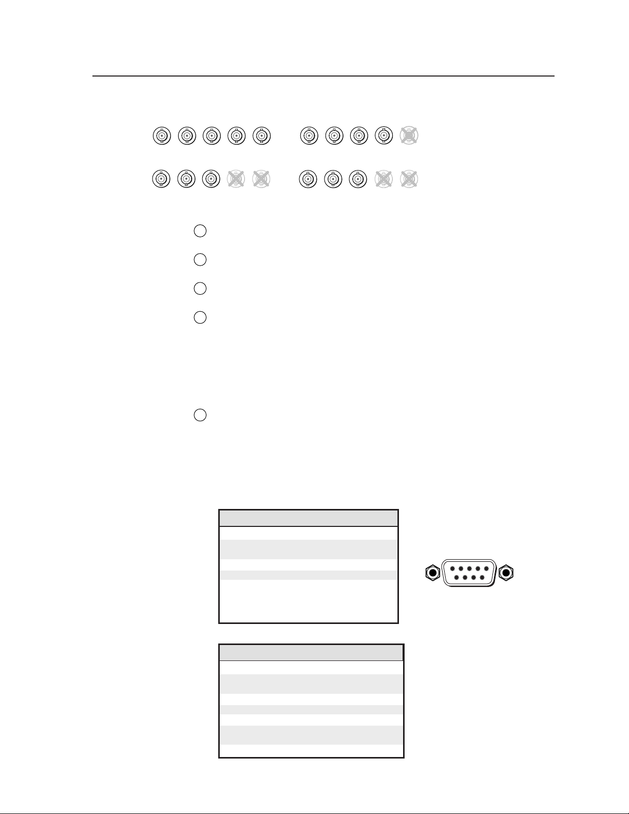
RGB and component video input BNC connectors — Connect a computer
4
video (RGBHV, RGBS, RGsB) or component video input via these five
female BNC connectors. Connect cables for the appropriate signal type, as
shown here.
R
/R-Y
RGBHV input
R
/R-Y
Buffered loop-through BNC connectors — For local monitor output of the
5
B
G
/Y
/B-Y
B
G
/Y
/B-Y
RGsB input
V
H
/HV
/R-Y
R
B
G
/Y
/B-Y
H
V
/HV
RGBS input
G
V
H
/HV
/R-Y
R
B
H
/Y
/B-Y
V
/HV
Component video input
(R-Y, Y, B-Y)
input, connect a monitor to these five female BNC connectors. Connect
cables for the appropriate signal type as shown in
Output BNC connectors — Connect coaxial cables from a display device to
6
above.
4
these five female BNC connectors for RGBHV, RGBS, RGsB, or component
video output, as follows:
VSC 900/900D • Installation and Operation2-4
/HV
DB9 Pin Locations
Female
51
96
/R-Y
R
B
/Y
/B-Y
G
V
H
/Y
R
/R-Y
/B-Y
B
G
V
/HV
H
RGBHV output
/R-Y
R
/B-Y
/Y
B
G
RGsB output
S-video output connector — Connect an S-video output device to this
7a
female 4-pin mini DIN connector.
SDI (serial digital interface) output connector — Connect an output device
7b
to this SDI component output female BNC.
Composite video output connector — Using a coaxial cable, connect a
8
composite video display device to this female BNC connector.
Genlock input and output connectors — An external blackburst signal
9
may be connected to the input (In) female BNC connector for genlocking the
video signal in broadcast or other sync-critical applications.
Connect any downstream equipment, which requires genlocking, to the
output (Out) female BNC connector to route the blackburst signal
throughout the system in broadcast or other sync-critical applications.
See Genlock and Vertical Interval Switching in this chapter.
RS-232/RS-422 port — This connector provides for two-way RS-232/RS-
10
422 communication. See chapter three, “Serial Communication”, for
information on how to install and use the control software and SIS
commands.
RGBS output
V
H
/HV
/R-Y
R
G
/Y
H
/B-Y
/HV
B
V
Component video output
(R-Y, Y, B-Y)
The default protocol is 9600 baud, 1 stop bit, no parity, and no flow control.
The rear panel RS-232/RS-422, 9-pin connector has the following pin
assignments:
Pin RS-232 function Description
1 – No connection
2 Tx Transmit data
3 Rx Receive data
4 – No connection
5 Gnd Signal ground
6 – No connection
7 – No connection
8 – No connection
9 – No connection
Pin RS-422 function Description
1 – No connection
2 Tx- Transmit ground
3 Rx- Receive ground
4 – No connection
5 Gnd Signal ground
6 – No connection
7 Rx+ Receive data
8 Tx+ Transmit data
9 – No connection
2-5VSC 900/900D • Installation and Operation
Installation and Operation, cont’d
Genlock and Vertical Interval Switching
Vertical interval switching provides for clean switching between signals from
several devices during the vertical blanking period of each signal. Vertical
interval switching between the VSC and another source with an external
switcher can be achieved by applying a composite sync signal at the Genlock In
connector. The sync signal can also be passed to another device via the Genlock
Out connector.
If the genlock connectors are used only for vertical interval switching, no
horizontal or subcarrier phase adjustments are required.
Genlock setup
Genlock differs from simple vertical interval switching in that an external device
(a black burst generator) generates a reference sync signal for the system, and
every device that uses that signal has its output signal’s horizontal and
subcarrier phases adjusted to exactly match that of the generator to allow precise
timing and full synchronization. Genlocked systems produce cleaner switches
between inputs than do those without this type of synchronization.
An oscilloscope is required for genlock setup, and a vectorscope is
recommended. Waveform monitors of types other than a vectorscope may give
the appearance that timing is adjusted correctly when it is 180 degrees out of
phase, which will result in incorrect colors or picture artifacts.
To synchronize the VSC’s video output with a genlock signal, follow these steps:
All equipment in the system must be powered up and turned on for at least
15 to 20 minutes before genlock setup adjustments can be made and before
the equipment is used in a genlocked application.
1. Power up and turn on all the devices that will use the genlock signal.
The devices must be on for at least 15 to 20 minutes before proceeding
with any adjustments.
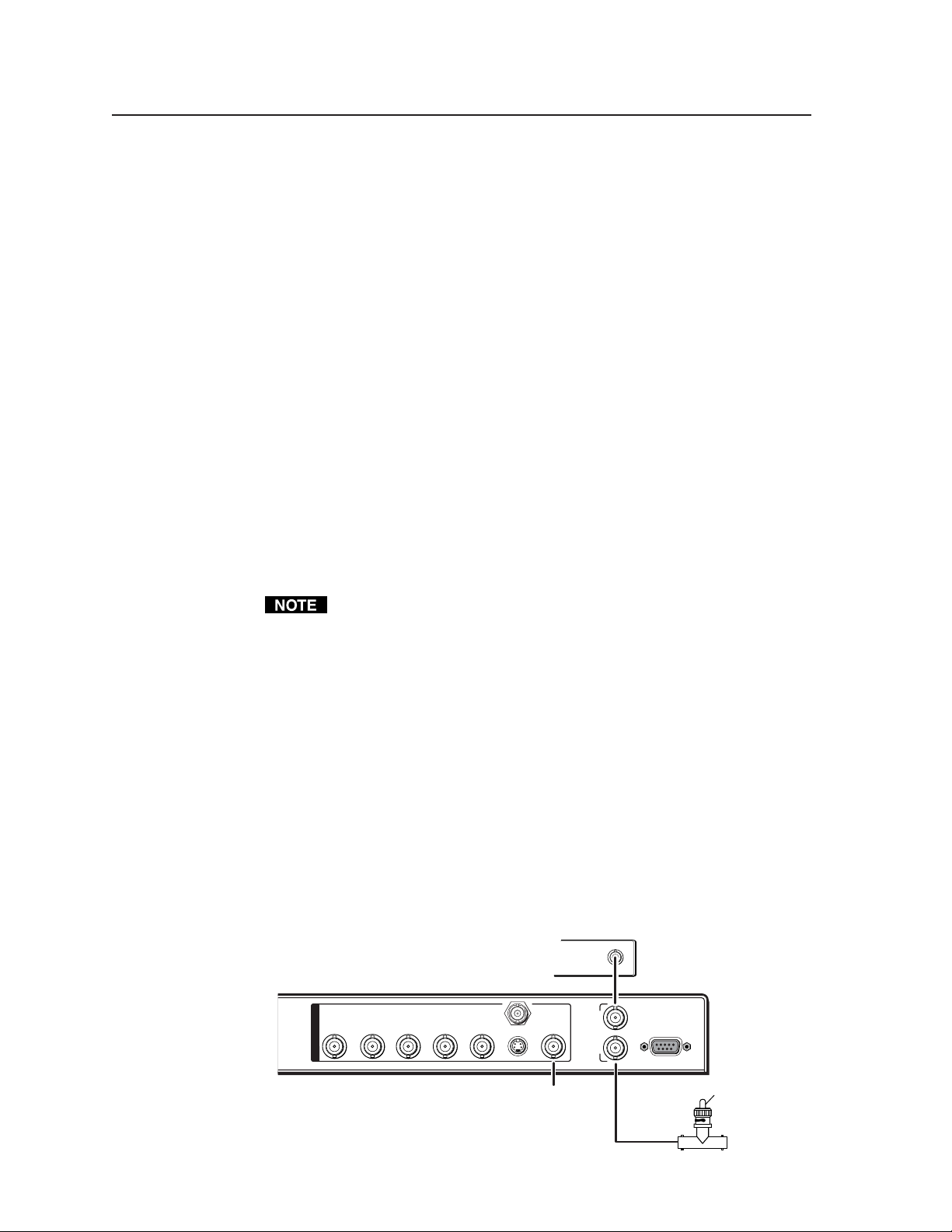
2. Connect the active timing source signal to the Genlock In connector on
the rear panel.
3. Connect the video input signals to the VSC, as described previously in
this chapter.
4. Connect the oscilloscope (“scope”) probe A to the Genlock Out
connector. This will provide the scope’s reference signal. In order to
avoid altering the genlock signal, use the cabling configuration that
will be used in the installation. Either connect the genlock signal cable
from the scope to the next device in the system to be timed, or provide
75 ohm termination at the scope’s genlock output.
Timing Source
S-VIDEO
SDI
VIDEO
O
U
T
R/R-Y
P
U
T
S
G/Y
B/B-Y H/H-Y
V
OUT
IN
G
E
N
L
O
C
K
OUT
RS-232
/422
To Scope Probe B
75 ohm Terminator
To Scope
Probe A
VSC 900/900D • Installation and Operation2-6
5. Connect scope probe B to the VSC’s composite video output connector.
6. Using the instructions for the scope you are using, set the scope to view
the signal’s horizontal phases. Adjust the horizontal phase by rotating
the horizontal Adjust (
this chapter). Adjust the horizontal phase until there is no (0°)
difference between the composite video output’s horizontal sync phase
and the genlock signal’s horizontal phase. See the “Oscilloscope
displays” section in this chapter.
7. Set the scope to view the subcarrier signals. Adjust the sub phase by
rotating the vertical Adjust (
difference between the genlock signal and the NTSC/PAL output (see
the “Genlock menu” section in this chapter).
8. View the horizontal phases again. If the phase difference is not zero,
repeat steps 6 and 7 until the settings do not change.
9. Once the settings are stable, disconnect the oscilloscope, and reconnect
the genlock cables.
10. Check the display(s) for proper colors and for undesirable artifacts in
the image(s). Make adjustments as necessary.
11. If other VSCs are part of this genlock daisy chain, connect the
oscilloscope to each device, and repeat this procedure.
Oscilloscope displays
What you see on the oscilloscope while adjusting the VSC to match the genlock
signal depends on the type of signal used, the type of oscilloscope, and the
procedure the scope requires. This section shows some examples of oscilloscope
displays.
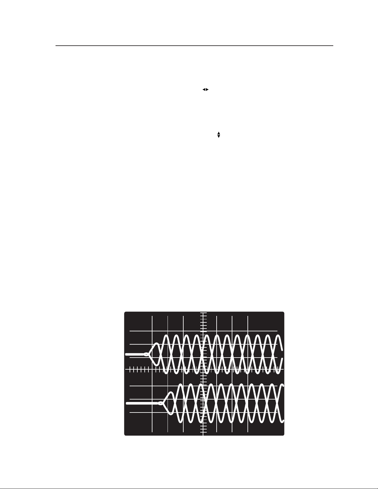
The following diagram shows the genlock input signal (top) and an out-ofalignment NTSC composite sync output signal (bottom) displayed on a
waveform monitor to check for alignment. When the phases are aligned, the
wave peaks on the bottom waveform should line up with those in the reference
signal above it.
) knob (see the “Genlock Menu” section in
) knob until there is a zero phase
Figure 2-4 — Superimposed waveforms
2-7VSC 900/900D • Installation and Operation
 Loading...