


SETUP & OPERATION MANUAL
FEATURES
 The table rides on 14 sealed, steel ball bearing rollers and is supported by architectural grade heavy-duty steel tubing.
 Easy to adjust, extruded aluminum miter fence for accurate miters from 0° to 45°.
 Adaptable to virtually all 10-14” table saws.
 New design sliding quick mount bracket for added cutting capacity. Cut up to 49”* with the crosscut fence positioned at the rear. Crosscut or miter up to 28”* with the fence at the front of the table.
 Quick connect mounting bracket allows for easy removal of the sliding table from the saw for users with space/storage limitations.
 Positive stop rail and locator pin quickly sets fence for commonly used miter angles.
SPECIFICATIONS
WORKING FLOOR SPACE (FRONT TO REAR)
78” (1980 MM)
WORKING FLOOR SPACE (TO LEFT OR RIGHT OF SAW) 30” (762 MM)
WIDTH OF SLIDING TABLE 26” (661 MM)
LENGTH OF SLIDING TABLE
30” (762 MM)
DISTANCE IN FRONT OF BLADE TO CUT AT 90°*
28” (711 mm)
DISTANCE FROM REAR OF BLADE TO CUT AT 90°*
49” (1245 MM)
LENGTH OF FENCE
54” (1372 MM)
LENGTH OF FENCE WITH EXTENSION STOP 91” (2311 MM)
WEIGHT
133 LBS (60.5 kg)
*Depending on the positioning of the mounting bracket on your saw.
SLIDING TABLE
SLIDING TABLE ONLY -
TABLE SAW SOLD SEPARATELY
MODEL
#50-SLT40P
REVISION 3 - NOVEMBER 2014
© Copyright General® International

GENERAL® INTERNATIONAL
8360 Champ-d’Eau, Montreal (Quebec) Canada H1P 1Y3 Telephone (514) 326-1161 • Fax (514) 326-5555 • www.general.ca
THANK YOU for choosing this Excalibur by General® International model 50-SLT40P Sliding Table. This sliding table has been carefully tested and inspected before shipment and if properly used and maintained, will provide you with years of reliable service. For your safety, as well as to ensure optimum performance and trouble-free operation, and to get the most from your investment, please take the time to read this manual before assembling, installing and operating the unitting the unit.
The manual’s purpose is to familiarize you with the safe operation, basic function, and features of this sliding table as well as the set-up, maintenance and identification of its parts and components. This manual is not intended as a substitute for formal woodworking instruction, nor to offer the user instruction in the craft of woodworking. If you are not sure about the safety of performing a certain operation or procedure, do not proceed until you can confirm, from knowledgeable and qualified sources, that it is safe to do so.
Once you’ve read through these instructions, keep this manual handy for future reference.
Disclaimer: The information and specifications in this manual pertain to the unit as it was supplied from the factory at the time of printing. Because we are committed to making constant improvements, General® International reserves the right to make changes to components, parts or features of this unit as deemed necessary, without prior notice and without obligation to install any such changes on previously delivered units. Reasonable care is taken at the factory to ensure that the specifications and information in this manual corresponds with
that of the unit with which it was supplied. However, special orders and “after factory” modifications may render some or all information in this manual inapplicable to your machine. Further, as several generations of this model of sliding table and several versions of this manual may be in circulation, if you own an earlier or later version of this unit, this manual may not depict your unit exactly. If you have any doubts or questions contact your retailer or our support line with the model and serial number of your unit for clarification.

GENERAL® MFG & GENERAL® INTERNATIONAL WARRANTY
All component parts of General® MFG, General® International and Excalibur by General International ® products are carefully inspected during all stages of production and each unit is thoroughly inspected upon completion of assembly.
Limited Lifetime Warranty
Because of our commitment to quality and customer satisfaction, General® MFG and General® International agree to repair or replace any part or component which upon examination, proves to be defective in either workmanship or material to the original purchaser for the life of the tool. However, the Limited Lifetime Warranty does not cover any product used for professionnal or commercial production purposes nor for industrial or educational applications. Such cases are covered by our Standard 2-year Limited Warranty only. The Limited Lifetime Warranty is also subject to the “Conditions and Exceptions” as listed below.
Standard 2-Year Limited Warranty
All products not covered by our lifetime warranty including products used in commercial, industrial and educational applications are warranted for a period of 2 years (24 months) from the date of purchase. General® MFG and General® International agree to repair or replace any part or component which upon examination, proves to be defective in either workmanship or material to the original purchaser during this 2-year warranty period, subject to the “conditions and exceptions” as listed below.
To file a Claim
To file a claim under our Standard 2-year Limited Warranty or under our Limited Lifetime Warranty, all defective parts, components or machinery must be returned freight or postage prepaid to General® International, or to a nearby distributor, repair center or other location designated by General® International. For further details call our service department at 1-888- 949-1161 or your local distributor for assistance when filing your claim.
Along with the return of the product being claimed for warranty, a copy of the original proof of purchase and a “letter of claim” must be included (a warranty claim form can also be used and can be obtained, upon request, from General® International or an authorized distributor) clearly stating the model and serial number of the unit (if applicable) and including an explanation of the complaint or presumed defect in material or workmanship.
CONDITIONS AND EXCEPTIONS:
This coverage is extended to the original purchaser only. Prior warranty registration is not required but documented proof of purchase i.e. a copy of original sales invoice or receipt showing the date and location of the purchase as well as the purchase price paid, must be provided at the time of claim.
Warranty does not include failures, breakage or defects deemed after inspection by General® MFG or General® International to have been directly or indirectly caused by or resulting from; improper use, or lack of or improper maintenance, misuse or abuse, negligence, accidents, damage in handling or transport, or normal wear and tear of any generally considered consumable parts or components.
Repairs made without the written consent of General® Internationallwill void all warranty.

TABLE OF CONTENTS
SAFETY RULES . . . . . . . . . . . . . . . . . . . . . . .5
IDENTIFICATION OF MAIN PARTS AND COMPONENTS . . . . . . . . . . . . . . . . . . . . . . .6
UNPACKING . . . . . . . . . . . . . . . . . . . . . . . .7
List of contents . . . . . . . . . . . . . . . . . . . . . . . . . . . . . .7 Additional requirements for set up . . . . . . . . . . . . .7
PREPARATION BEFORE ASSEMBLY . . . . . . . . . .8
Remove table left extension wing, rip fence
and guide rails . . . . . . . . . . . . . . . . . . . . . . . . . . . . . .8
STEP 1 - LEGS AND BRACKET PRE-ASSEMBLY . . .8
STEP 2 - BRACKETS AND INNER RAIL INSTALLATION . . . . . . . . . . . . . . . . . . . . . . .9
Attach the main mounting bracket to the saw table . . . . . . . . . . . . . . . . . . . . . . . . . . . . . . . . . . . . . .9 Attach the quick mount bracket . . . . . . . . . . . . . . .9 Attach the rear inner leg mount to the inner guide rail . . . . . . . . . . . . . . . . . . . . . . . . . . . . . . . . . .10 Attach the inner guide rail to the quick
mount bracket . . . . . . . . . . . . . . . . . . . . . . . . . . . . .10 Install the switch mount bracket . . . . . . . . . . . . . .10
STEP 3 - CROSS BRACES INSTALLATION . . . . .11
Install the cross braces . . . . . . . . . . . . . . . . . . . . . .11
STEP 4 - TABLE AND FENCE INSTALLATION . . . .11
Install the sliding table . . . . . . . . . . . . . . . . . . . . . .11 Bearing adjustments . . . . . . . . . . . . . . . . . . . . . . . .12 Install the angle adjustment rail . . . . . . . . . . . . . .13 Cross cut fence assembly . . . . . . . . . . . . . . . . . . .14
FINE TUNING ADJUSTMENTS . . . . . . . . . . . . .16
Leveling the sliding table with the saw table . . . .16 Setting the sliding table tracking . . . . . . . . . . . . . .16 Squaring the cross cut fence to the blade . . . . .18 Set the 90º stop with the fence in the front
position . . . . . . . . . . . . . . . . . . . . . . . . . . . . . . . . . . .19 Set the 90º stop with the fence in the rear
position . . . . . . . . . . . . . . . . . . . . . . . . . . . . . . . . . . .20
BASIC OPERATIONS . . . . . . . . . . . . . . . . . . .21
Setting and using the sliding scale . . . . . . . . . . . .21 Check points . . . . . . . . . . . . . . . . . . . . . . . . . . . . . .23 Panel cutting . . . . . . . . . . . . . . . . . . . . . . . . . . . . . .23 Miter cuts . . . . . . . . . . . . . . . . . . . . . . . . . . . . . . . . . .25
USAGE TIPS . . . . . . . . . . . . . . . . . . . . . . . .25
RECOMMENDED OPTIONAL ACCESSORIES . . . .26
PARTS LIST AND DIAGRAMS . . . . . . . . . .27 - 31
CONTACT INFORMATION . . . . . . . . . . . . . . . .32

Rules for Safe Operation
To help ensure safe operation, please take a moment to learn the machine’s applications and limitations, as well as potential hazards. General International disclaims any real or implied warranty and hold itself harmless for any injury that may result from the improper use of it’s equipment.
1.Do not operate the saw when tired, distracted, or under the effects of drugs, alcohol or any medication that impairs reflexes or alertness.
2.The working area should be well lit, clean and free of debris.
3.Keep children and visitors at a safe distance when the saw is in operation; do not permit them to operate the saw.
4.Childproof and tamper proof your shop and all machinery with locks, master electrical switches and switch keys, to prevent unauthorized or unsupervised use.
5.Stay alert! Give your work your undivided atten tion. Even a momentary distraction can lead to serious injury.
6.Fine particulate dust is a carcinogen that can be hazardous to health. Work in a well-ventilated area and whenever possible use a dust collector and wear eye, ear and respiratory protection devices.
7.Do not wear loose clothing, gloves, bracelets, necklaces or other jewelry while the saw is in operation. Wear protective hair covering to contain long hair and wear non-slip footwear.
8.Be sure that adjusting wrenches, tools, drinks and other clutter are removed from the machine and/or the feed table surface before operating.
9.Keep hands well away from the blade and all moving parts. Use a brush, not hands, to clear away chips and dust.
10.Be sure that the blade is securely installed and in proper cutting direction before operation.
11.Be sure the blade has gained full operating speed before beginning to cut.
12.Always use a clean, properly sharpened blade. Dirty or dull blades are unsafe and can lead to accidents.
13.If using a power feeder, stop the feeder before stopping the table saw.
14.Do not push or force stock into the blade. The saw will perform better and more safely when working at the rate for which it was designed.
15.Use suitable support when cutting stock that does not have a flat surface. Always hold stock firmly against the fence when ripping, or against the miter gauge when cross-cutting.
16.To minimize risk of injury in the event of workpiece kickback, never stand directly in-line with the blade or in the potential kickback path of the work piece.
17.Avoid working from awkward or off balance positions. Do not overreach while cutting; keep both feet on floor. Never lean over or reach over the blade and never pull the work piece over the blade from behind. Use out feed support or have an assistant help when ripping long material.
18.Keep blade guards in place and in working order. If a guard must be removed for maintenance or cleaning, be sure it is properly reattached before using the tool again.
19.Never leave the machine running with the power on when not in operation.
20.Use of parts and accessories NOT recommended by GENERAL→ INTERNATIONAL may result in equipment malfunction or risk of injury.
21.Never stand on machinery. Serious injury could result if the tool is tipped over or if the blade is unintentionally contacted.
22.Always disconnect tool from power before servicing or changing accessories such as blades, or before performing any maintenance, cleaning or adjustments, or if the machine will be left unattended.
23.Make sure that switch is in "OFF" position before plugging in the power cord.
24.Make sure the tool is properly grounded. If equipped with a 3-prong plug it should be used with a three-pole receptacle. Never remove the third prong.
25.Do not use this sliding table for other than its intended use. If used for other purposes, GENERAL→ INTERNATIONAL disclaims any real implied warranty and holds itself harmless for any injury, which may result from that use.
5
SLIDING TABLE |
50-SLT40P |
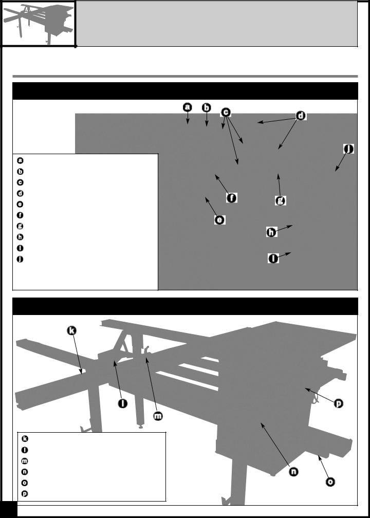
IDENTIFICATION OF MAIN PARTS AND COMPONENTS |
RAIL & BRACE ASSEMBLY |
MAIN MOUNTING BRACKET |
QUICK MOUNT BRACKET |
CROSS BRACE (3X) |
FRONT OUTSIDE BRACKET (2X) |
INNER GUIDE RAIL |
REAR INSIDE BRACKET |
FENCE STORAGE BRACKET (2X) |
SUPPORT LEG (3X) |
LEVELING FOOT (3X) |
OUTER GUIDE RAIL |
TABLE & CROSS CUT FENCE ASSEMBLY |
CROSS CUT FENCE |
MITER CLAMP |
SLIDING FLIP-UP STOP |
ANGLE ADJUSTMENT RAIL |
RETURN HANDLE |
SLIDING TABLE |
6 |

UNPACKING
Carefully unpack and remove the unit and its components from the box and check for missing or damaged items as per the list of contents below.
NOTE: Please report any damaged or missing items to your GENERAL® INTERNATIONAL distributor immediately.
LIST OF CONTENTS |
QTY |
|
|
|
|
BOX 1 - FENCE & RAILS
OUTER GUIDE RAIL . . . . . . . . . . . . . . . . . . . . . . . . . . . .1 INNER GUIDE RAIL . . . . . . . . . . . . . . . . . . . . . . . . . . . .1 FENCE WITH FENCE EXTENSION POST . . . . . . . . . . . .1 ANGLE ADJUSTMENT RAIL WITH RETURN HANDLE . . .1
BOX 2 - TABLE & OTHER COMPONENTS
TABLE ASSEMBLY . . . . . . . . . . . . . . . . . . . . . . . . . . . . .1 QUICK MOUNT BRACKET . . . . . . . . . . . . . . . . . . . . . .1 MAIN MOUNTING BRACKET . . . . . . . . . . . . . . . . . . . .1 SLIDING FLIP-UP STOP ASSEMBLY . . . . . . . . . . . . . . . .1 ROLLER BEARING ASSEMBLY . . . . . . . . . . . . . . . . . . . .2 FENCE PIVOT PIN ASSEMBLY . . . . . . . . . . . . . . . . . . . .1 SUPPORT LEG . . . . . . . . . . . . . . . . . . . . . . . . . . . . . . . .3 CROSS BRACE . . . . . . . . . . . . . . . . . . . . . . . . . . . . . . .3 OUTSIDE BRACKET . . . . . . . . . . . . . . . . . . . . . . . . . . . .2 REAR BRACKET . . . . . . . . . . . . . . . . . . . . . . . . . . . . . . .1 RATCHET LEVER . . . . . . . . . . . . . . . . . . . . . . . . . . . . . .1 MITER CLAMP ASSEMBLY . . . . . . . . . . . . . . . . . . . . . . .1 T-NUT . . . . . . . . . . . . . . . . . . . . . . . . . . . . . . . . . . . . . . .1 SWITCH MOUNT BRACKET . . . . . . . . . . . . . . . . . . . . . .1 FENCE EXTENSION STOP MOUNT . . . . . . . . . . . . . . . .1 5 MM T-HANDLE ALLEN WRENCH . . . . . . . . . . . . . . . .1 6 MM T-HANDLE ALLEN WRENCH . . . . . . . . . . . . . . . .1
MOUNTING HARDWARE/FASTENER KIT
For your convenience, the mounting hardware for the sliding table assembly is packaged into 4 separate bags identified 1, 2, 3 and 4, respectively. For each main assembly step in this manual, the bag containing the required hardware will be indicated.
BOX 1 - FENCE & RAILS
BOX 2 - TABLE & OTHER COMPONENTS
|
|
|
HARDWARE |
|
|
|
|
|
|
|
|
|
||
ADDITIONAL REQUIREMENTS FOR SET UP |
|
|
|
|
|
|
|
|
|
|
|
|
||
BAG 1 |
|
|
BAG 2 |
|
|
BAG 3 |
|
|
BAG 4 |
|
||||
• 10/13/14 mm open |
• Phillips Screwdriver |
|
|
|
|
|
|
|
|
|||||
|
|
|
|
|
|
|
|
|
|
|
|
|
||
end & or socket wrench |
• Measuring tape |
|
|
|
|
|
|
|
|
|
|
|
|
|
• Machinist square |
• Level |
|
|
|
|
|
|
|
|
|
|
|
|
|
|
|
|
|
|
|
|
|
|
|
|
|
|
|
|
|
|
|
|
|
|
|
|
|
|
|
|
|
|
|
7

PREPARATION BEFORE ASSEMBLY
VERY IMPORTANT!
BEFORE PROCEEDING WITH THE ASSEMBLY STEPS MAKE SURE THE SAW TABLE IS LEVELED WITH THE FLOOR, PLACING A LEVEL ON THE TABLE. USE SHIMS (OR LEVELING FEET IF APPLICABLE) FOR LEVELING IF NEEDED.
REMOVE TABLE LEFT EXTENSION WING, RIP FENCE AND GUIDE RAILS
For most installations, in order for the sliding table to be as close as possible to the blade the table extension wing must be removed. To avoid interfering with the movement of the sliding table, the rip fence guide rails will also need to be temporarily removed and may need to be shortened so that they do not protrude beyond the end of the main table.
1.Make a reference mark on the rip fence guide rails
even with the end of the main table (not the exten-
sion wing  and then remove and set aside the fence and rails
  .
.
2.Remove the left extension wing  from the main table and set it aside.
Note: Do not cut the fence rails just yet - wait until you are ready to re-install the fence after assembling, installing and aligning the sliding table. Some fence systems may allow you to simply slide or re-mount the guide rails further to the right, allowing you to increase the rip cutting capacity of the saw to the right of the blade.
STEP 1 - LEGS AND BRACKET PRE-ASSEMBLY


 HARDWARE
 BAG
BAG 1*
1*


*All mounting hardware required for Assembly Step 1 can be found in hardware bag 1.
NOTE: Adjustments made during the initial set-up phase may be approximate. Once the table is assembled you will be able to make minor adjustments for leveling and fine tuning at that time.
1.Install a leveling foot  , a hex nut
  , and a flat washer
  to the bottom of all three support legs
  , as shown in
  .
.
Tip: Leave a space of approximately 1" between the feet and legs as shown in  to facilitate the leveling of the sliding table with the saw table when you proceed to fine tuning adjustments later.
1”
8

CLOSE UP
2.Fit a support leg into the three brackets as shown, then tighten with two hex bolts and flat washers.
Tip: Select the second hole from the top of the bracket as shown in  to allow room for fine tuning adjustments later.
3.Install a fence storage bracket  onto the two outer legs
  as shown in
  .
.
STEP 2 - BRACKETS AND INNER RAIL INSTALLATION


 HARDWARE
 BAG
BAG
 2*
2*


*All mounting hardware required for Assembly Step 2 can be found in hardware bag 2. After having completed Step 2, four hex bolts and four washers will be left over. Put them aside for now.
ATTACH THE MAIN MOUNTING BRACKET TO THE SAW TABLE
Note: Four hex bolts and flat washers are supplied with your Sliding Table. However, if they do not thread into the mounting holes on your table, use the fasteners that were supplied with the saw to hold the extension wing in place.
1.Check to see which holes on the main mounting bracket aligns on the saw’s main table mounting holes.
2.Secure the main mounting bracket to the main table
using as many fasteners as possible, at minimum, the rear two holes of the table  .
.
1/8” |
Tip: For added stability, holes may be drilled into the saw table  if necessary.
Note: The bracket should be approximately 1/8” from the top of the table  .
.
ATTACH THE QUICK MOUNT BRACKET
1.Secure the quick mount bracket to the main mount-
ing bracket with ALL 4 socket head cap screws and 4
washers  , using the supplied 6 mm t-handle wrench
  , as shown in
  .
.
Note: Position the quick mount bracket with the square holes  towards the rear of the saw.
9

INNER RAIL UNDERSIDE VIEW - THREADED HOLES
|
|
|
|
|
|
|
|
|
|
|
|
|
|
|
|
|
|
|
|
|
|
|
|
|
|
|
|
|
|
|
|
|
|
|
|
|
|
|
|
|
|
|
REAR INNER LEG MOUNT |
|
|
|
QUICK MOUNT BRACKET |
|
|
|
|
|
|||
|
|
|
|
|
|
|
|
|
|
|
|
|
|
|
|
|
|
|
|
|
|
|
|
|
|
||
|
|
|
|
|
|
|
SWITCH MOUNT BRACKET |
|
|
||||
|
|
|
|
|
|
|
|
|
|
||||
|
|
|
|
|
|
|
|
|
|||||
|
|
|
INNER RAIL SIDE VIEW - ACCESS HOLES |
|
|||||||||
|
|
|
|
|
|
|
|
|
|
|
|
|
|
|
|
|
|
|
|
|
|
FASTENER ACCESS HOLES (X6) |
|
|
|
|
|
|
|
|
|
|
SLIDING TABLE BEARING ACCESS HOLES |
|
|
|
|
|
|
|
|
|
|
ATTACH THE REAR INNER LEG MOUNT TO THE INNER GUIDE RAIL
|
|
|
|
|
|
|
|
|
|
|
|
|
|
|
|
|
|
|
|
|
|
|
|
|
|
|
|
|
|
|
|
|
|
|
|
|
|
|
|
|
|
|
|
|
|
|
|
|
|
|
|
|
|
|
|
|
|
|
|
|
|
|
|
|
|
|
|
|
|
|
|
|
|
|
|
|
|
|
|
|
|
|
|
|
|
|
|
|
|
|
|
|
|
|
|
|
|
|
|
|
|
INNER REAR LEG MOUNT |
|
|
|
|
|
|
|
|
|
|
|
|
|
||||
|
|
|
|
|
|
|
|
|
|
|
|
|
|
|
1. Using the quick mount bracket as a height gau- |
|
2. Attach the rear leg mount to the inner rail using 2 |
||||||||||||
ge , adjust the height of the rear inner leg mount |
|
hex bolts and 2 washers , aligning the leg mount |
||||||||||||
|
by finding the hole that comes closest and/or |
|
with the back two threaded holes in the rail , as |
|||||||||||
by adjusting the leveling foot , until the top of the |
|
shown in . |
||||||||||||
rear inner bracket is even with the quick mount bra- |
|
|
|
|
|
|
|
|
|
|||||
cket . |
|
|
|
|
|
|
|
|
|
|||||
ATTACH THE INNER GUIDE RAIL TO THE QUICK MOUNT BRACKET |
INSTALL THE SWITCH MOUNT BRACKET |
|||||||
|
|
|
|
|
|
|
|
|
|
|
|
|
RAIL UNDERSIDE VIEW |
|
|
|
Final installation shown for clarity only |
|
|
|
|
|
|
|
|
|
|
|
|
|
|
|
|
|
|
QUICK MOUNT BRACKET |
Attach the inner rail to the quick mount bracket using 4 hex bolts and 4 washers  .
.
Note: Verify that the inner rail is somewhat parallel with the saw table  before tightening the bolts.
SWITCH MOUNT BRACKET |
Install the switch mount bracket on the front end of the inner rail as shown in  , using 2 hex bolts and 2 washers
  .
.
10
 Loading...