


 The over arm blade cover system with dust collection capability is designed for more efficient dust collection, sawdust is immediately removed and will not accumulate on the table top.
 A tubular steel column supports the telescopic over arm boom.
 4” main boom and 3” inner boom.
 Flexible 3” hose connects the blade cover to the boom.
 Heavy-duty, see-through blade cover, counterbalanced for smooth efficient operation.
BOOM HEIGHT ABOVE FLOOR
33 3/4” TO 48 1/2” (860 TO 1230 mm)
BOOM HEIGHT ABOVE TABLE 13 3/8” (340 mm)
MAIN BOOM DIAMETER 4” (102 mm)
INNER BOOM DIAMETER 3” (77 mm)
DISTANCE BETWEEN BLADE AND END OF EXTENSION TABLE
39 3/4” TO 67” (1010 TO 1700 mm)
BLADE COVER DIMENSIONS 3 1/8” X 17”
(80 x 432 mm) 50-EXBC10
3 1/8 X 20 1/8”
(80 x 512 mm) 50-EXBC14
WEIGHT
58 LBS (26.5 kg)
BLADE COVER SYSTEM ONLY -
TABLE SAW & DUST COLLECTOR SOLD SEPARATELY
REVISION 3 September 10/07
© COPYRIGHT GENERAL INTERNATIONAL 09/2007

GENERAL® INTERNATIONAL
8360 Champ-d’Eau, Montreal (Quebec) Canada H1P 1Y3
Telephone (514) 326-1161 • Fax (514) 326-5555
www.general.ca
THANK YOU for purchasing the Excalibur by General® International model 50-EXBC10/14 Blade Cover. This blade cover has been carefully tested and inspected before shipment and if properly used and maintained, will provide you with years of reliable service. To ensure optimum performance and trouble-free operation, and to get the most from your investment, please take the time to read this manual before assembling, installing and operating the unit.
The manual’s purpose is to familiarize you with the safe operation, basic function, and features of this blade cover as well as the set-up, maintenance and identification of its parts and components. This manual is not intended as a substitute for formal woodworking instruction, nor to offer the user instruction in the craft of woodworking. If you are not sure about the safety of performing a certain operation or procedure, do not proceed until you can confirm, from knowledgeable and qualified sources, that it is safe to do so.
Once you’ve read through these instructions, keep this manual handy for future reference.
GENERAL® INTERNATIONAL WARRANTY
All component parts of Excalibur by General® International products are carefully tested and inspected during all stages of production, and each unit is thoroughly inspected upon completion of assembly. Because of our commitment to quality and customer satisfaction, General® International agrees to repair or replace, within a period of 24 months from date of purchase, any genuine part or parts which, upon examination, prove to be defective in workmanship or material. In order to obtain this warranty, all defective parts must be returned freight pre-paid to General® International Mfg. Co., Ltd. Repairs attempted without our written authorization will void this warranty.
Disclaimer: The information and specifications in this manual pertain to the unit as it was supplied from the factory at the time of printing. Because we are committed to making constant improvements, General® International reserves the right to make changes to components, parts or features of this unit as deemed necessary, without prior notice and without obligation to install any such changes on previously delivered units. Reasonable care is taken at the factory to ensure that the specifications and information in this manual corresponds with that of the unit with which it was supplied. However, special orders and “after
factory” modifications may render some or all information in this manual inapplicable to your unit. Further, as several generations of this blade cover and several versions of this manual may be in circulation, if you own an earlier or later version of this unit, this manual may not depict your unit exactly. If you have any doubts or questions contact your retailer or our support line with the model of your unit for clarification.

Rules for Safe Operation
To help ensure safe operation, please take a moment to learn the machine’s applications and limitations, as well as potential hazards. General International disclaims any real or implied warranty and hold itself harmless for any injury that may result from the improper use of it’s equipment.
1.Be sure to read, understand and follow all warnings and safety guidelines supplied with your table saw and dust collector.
2.Do not use any machinery when tired, distracted, or under the effects of drugs, alcohol or any medication that impairs reflexes or alertness.
3.Keep safety guards in place and in working order.
4.Keep work area well lit, clean and free of debris.
5.Do not use tools in dangerous environments. Do not use power tools in damp or wet locations or expose them to rain.
6.Keep children and visitors at a safe distance w h e n machinery is in operation. Do not permit them to operate any machinery.
7.Childproof and tamper proof your shop and all machinery with locks, master electrical switches and switch keys, to prevent unauthorized or unsupervised use.
8.Don’t force the tool. It will function better and safer at the rate for which it was designed.
9.Wear proper apparel. Do not wear loose clothing, gloves, neckties, rings, bracelets or other jewelry which may get caught in moving parts. Non-slip footwear is also recommended. Wear protective hair covering to contain long hair.
10.Stay alert! Give your work your undivided attention. Even a momentary distraction can lead to serious injury.
11.Always use safety glasses. Use a face or dust mask if cutting operation is dusty. Everyday glasses only have impact resistant lenses - they are NOT safety glasses.
12.Do not overreach. Keep proper footing and balance at all times.
13.Disconnect power tools before servicing and when changing blades.
14.Check damaged parts. Before further use of the tool, a guard or other part that is damaged should be carefully checked to determine that it will operate properly and perform its intended function. Check for alignment and/or binding of moving parts, breakage of parts, mounting and any other conditions that may affect its operation. A guard or other part that is damaged should be replaced or properly repaired.
15.Never leave power tool running while unattended. Turn power off. Don’t leave the tool until it comes to a complete stop.
16.Be sure that adjusting wrenches, tools and other clutter are removed from the unit and/or the table surfaces before starting the machine.
17.Use of parts and accessories not recommended by General® International may result in equipment
malfunction or risk of injury.
18.Do not use this blade cover for any purpose other
than its intended use. If used for other purposes, General® International disclaims any real or
implied warranty and holds itself harmless for any injury which may result from such use.
OVERARM BLADE COVER SYSTEM
50-EXBC10/14
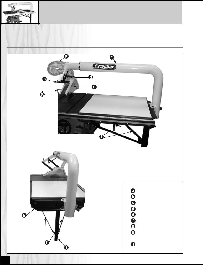
IDENTIFICATION OF MAIN PARTS AND COMPONENTS
|
FRONT VIEW |
|
DUST HOSE |
|
SWING ARM |
|
BOOM ASSEMBLY |
|
HOOD FRAME |
|
LENSES |
|
DIAGONAL BRACES |
|
BUMPER HANDLE |
|
BOOM MOUNT - |
|
CHANNEL |
SIDE VIEW |
EXTENSION LEG |
4

UNPACKING AND SET-UP
ADDITIONAL REQUIREMENTS FOR SET UP |
|
• Drill with drill bits |
* |
• 5/16”, 7/16” and 9/16” wrenches and/or socket set |
|
• Standard and Phillips screwdrivers |
|
• Pencil |
|
• 1/8” Allen Key |
|
*NOTE: Additional hardware nuts, bolts, washers & wood screws may be required to fasten the diagonal braces to your extension table.
UNPACKING
Carefully unpack and remove the unit and its components from the box and check for missing or damaged items as per the list of contents below.
NOTE: Please report any damaged or missing items to your GENERAL® INTERNATIONAL distributor immediately.
LIST OF CONTENTS
Separate and verify that all parts are in your accessories hardware bags.
|
QTY |
a. HOOD ASSEMBLY . . . . . . . . . . . . . . . . . . . . . . . . . . . . . |
1 |
b. DIAGONAL BRACES . . . . . . . . . . . . . . . . . . . . . . . . . . . . |
2 |
c. EXTENSION LEG . . . . . . . . . . . . . . . . . . . . . . . . . . . . . . . |
1 |
d. BOOM ASSEMBLY . . . . . . . . . . . . . . . . . . . . . . . . . . . . . |
1 |
e. DUST HOSE . . . . . . . . . . . . . . . . . . . . . . . . . . . . . . . . . . . |
1 |
f. BOOM MOUNT CHANNEL . . . . . . . . . . . . . . . . . . . . . . . |
1 |
g. PARTS BAG . . . . . . . . . . . . . . . . . . . . . . . . . . . . . . . . . . . |
1 |
Parts Bag consists of |
QTY |
a. 1/4”-20 BOLT X 1 1/2” L………….. |
6 |
b. 1/4”-20 HEX NUT ……………….. |
16 |
c. 1/4” WASHER ……………………. |
12 |
d. 3” HOSE CLAMP…………………. |
2 |
e. 1/4” SPLIT LOCK WASHER . . . . . |
8 |
f. 1/4”-20 X 4 EYE BOLT…………… |
2 |
g. 1/4”-20 X 3/4 FLAT HEAD BOLT… |
2 |
h. LOCK KNOB………………………. |
2 |
i. ANGLE BRACKET ……………….. |
2 |
j. 1/4”-20 SCREW X 1/2”L…………. |
4 |
k. 5/16” NUT. . . . . . . . . . . . . . . . . . |
1 |
l. 5/16” X 1-1/2” HEX BOLT . . . . . . |
1 |
|
|
|
|
5
 Loading...