

Page 1

OperatiOn ManUaL
Version 11.02 - July 2013
Page 2

Page 3

OPERATION MANUAL Multicam LSM 11.02
Copyright
EVS Broadcast Equipment S.A.– Copyright © 2003-2013. All rights reserved.
Disclaimer
The information in this manual is furnished for informational use only and subject to
change without notice. While every effort has been madeto ensurethat the information
contained in this usermanual is accurate, up-to-date andreliable, EVS Broadcast
Equipment cannot be held responsible for inaccuracies orerrors that may appear in this
publication.
Improvement Requests
Yourcomments will help us improve the quality of the user documentation. Do not
hesitate to send improvement requests, or report any erroror inaccuracy on this user
manual by e-mail to doc@evs.com.
Regional Contacts
The address and phone number of the EVS headquarters are usually mentioned in the
Help > About menu in the user interface.
You will find the full list of addresses andphonenumbers of local offices either at the end
of this usermanual (formanuals on hardwareproducts) or at the following pageon the
EVS website: http://www.evs.com/contacts.
User Manuals on EVS Website
The latest versionof the user manual, if any, and other user manuals on EVS products
can be found on the EVS downloadcenter, on the following webpage:
http://www.evs.com/downloadcenter.
I
Page 4

EVS Broadcast Equipment S.A. Issue 11.02.A July2013
Table of Contents
TABLE OF CONTENTS II
WHAT'S NEW? VII
1. OVERVIEW 1
2. WORKING INTERFACES 2
2.1. Overview 2
2.2. Remote Panel Controls 4
2.2.1. General Layout 4
2.2.2. LED Colors 6
2.2.3. Function Keys & Small Keys 7
2.2.4. Soft Keys andLCD Display 8
2.2.5. Jog Dial 9
2.2.6. Lever 9
2.2.7. Keyboard Locking 10
2.3. Remote Panel Operations 11
2.3.1. Main Menu 11
2.3.2. Function of the Small Keys 13
2.3.3. Function of the Operational Block 1 Keys 13
2.3.4. Function of the Operational Block 2 Keys 16
2.3.5. Rebooting the System from the Remote Panel 19
3. CONTROL MODES 20
3.1. Live, Search or Playback Mode 20
3.2. 1PGM+PRV Mode 21
3.2.1. 1PGM+PRV Mode 21
3.2.2. 1PGM+PRV Primary Menu Controls 22
3.2.3. 1PGM+PRV Secondary Menu Controls 23
3.2.4. Full Control and Lever Control 26
3.3. Multi PGM Mode 26
3.3.1. Multi PGM Overview 26
3.3.2. Multi PGM Primary Menu Controls 27
3.3.3. Multi PGM Secondary Menu Controls 30
3.4. Synchronization Mode (Switch To In) 31
3.5. Preference Mode (PREF) 31
3.6. Controlled and Primary Channels 32
3.7. Secondary Controller 32
II Table of Contents
Page 5

OPERATION MANUAL Multicam LSM 11.02
4. CLIP MANAGEMENT 34
4.1. Introduction 34
4.1.1. Clip Structure 34
4.1.2. Clip Numbering Hierarchy 35
4.1.3. Clip Availability on Disks 37
4.2. Clip Functions onthe Remote Panel 37
4.2.1. Remote Panel Interface 37
4.2.2. Remote Panel Functions 38
4.3. Clip Functions onthe VGA 41
4.3.1. VGA Interface - Clip Screen 41
4.3.2. VGA Functions - Clip Screen 43
4.3.3. VGA Interface - VDR Panel 48
4.3.4. VGA Functions - VDR Panel 49
4.4. Operations onClips 51
4.4.1. Creating and Saving Clips 51
4.4.2. Recalling and Playing Back Clips 53
4.4.3. Deleting Clips 57
4.4.4. Copying andMoving Clips 59
4.4.5. Naming a Clip 62
4.4.6. Restriping Clips 63
4.4.7. Searching for Clips by Timecode 65
4.4.8. Shortening a Clip 66
4.4.9. Cancelinga Network Copy 67
4.4.10. Changing the Primary Camera of a Clip 68
5. PLAYLIST MANAGEMENT 69
5.1. Introduction 69
5.2. Selecting Playlists or Timelines 70
5.3. Playlist Functions on the Remote Panel 71
5.3.1. Edit and Playout Modes 71
5.3.2. Functions in Playlist Edit Mode 72
5.3.3. Functions in Playlist Playout Mode 74
5.4. Playlist Functions on the VGA 75
5.4.1. VGA Playlist Screen 75
5.4.2. VGA Playlist Bank Screen 76
5.4.3. Editing Functions in VGA Playlist Screen 77
5.5. Operations onPlaylists 78
5.5.1. Setting and LoadingPlaylists 78
5.5.2. Rolling a Playlist 79
5.5.3. Deleting Playlists 80
5.5.4. Copying Playlists 81
5.5.5. Naming a Playlist or Playlist Element 85
5.5.6. Consolidating a Playlist 86
5.5.7. Generating a Continuous TC in a Playlist 87
Table of Contents III
Page 6

EVS Broadcast Equipment S.A. Issue 11.02.A July2013
5.6. Operations onClips in Playlists 88
5.6.1. Adding Clips in a Playlist 88
5.6.2. Deleting andMoving Playlist Elements 92
5.6.3. Browsing Within a Playlist 93
5.6.4. Changing the Camera Angle of a Playlist Element 94
5.6.5. Adding Cuts in Playlist Elements 94
5.6.6. Trimming Clips into a Playlist 95
5.6.7. Sortingthe Playlist Elements by TC IN 96
5.7. Transition and Audio Operations 97
5.7.1. Overview on Transition Effects 97
5.7.2. Adding Transition Effects in a Playlist 100
5.7.3. Using the Replace Function 101
5.7.4. Swapping Audio Tracks 105
5.7.5. Adding an Auxiliary Audio Clip 108
5.7.6. Using the Split Audio Mode 109
5.7.7. Extendinga Transition in Split Audio 112
5.7.8. V Base Editing in Split Audio 115
5.7.9. A Base Editing in Split Audio 117
6. TIMELINE MANAGEMENT 121
6.1. Introduction 121
6.2. Timeline Mode 122
6.2.1. Overview of the TimelineMode 122
6.2.2. Functions in Timeline Mode 123
6.2.3. Display in Timeline Mode 125
6.3. Managing Timelines 127
6.3.1. Creating Timelines 127
6.3.2. Copying Timelines 129
6.4. Editing Timelines 130
6.4.1. Overview of Editing Features 130
6.4.2. Adding Clips to a Timeline 132
6.4.3. Adding Cuts in Timeline Elements 132
6.4.4. Inserting Material into a Timeline 134
6.4.5. Deleting Part of a Timeline 138
6.4.6. Extendinga Timeline Element 139
6.4.7. Changing the Speed of a Timeline Element 142
6.4.8. Adding Transition Effects in a Timeline 144
6.5. Playing Out Timelines 146
7. KEYWORD MANAGEMENT 148
7.1. Overview 148
7.2. Managing KeywordFiles 150
7.3. Assigning Keywords 153
7.4. Clearing Keywords 156
IV Table of Contents
Page 7

OPERATION MANUAL Multicam LSM 11.02
7.5. Editing the Rankingof a Clip 156
7.6. Naming a Clip Using the Keywords 157
7.7. Searching the Database Using the Keywords 157
8. OPERATION ON XNET NETWORK 165
8.1. Overview 165
8.2. Selecting a Network Server 165
8.3. Recalling and Playing Back a Remote Clip 168
8.4. Naming a Remote Clip 169
8.5. Modifying IN andOUT Points of a Remote Clip 169
8.6. Inserting Remote Clips into a Playlist 170
8.7. Rolling a Playlist with Remote Clips 170
8.8. Creating Local Clips with Remote Record Trains 171
8.9. Working with Mapped Network Cameras 172
8.10. Disconnecting from XNet 172
9. ADVANCED CONTROL MODES 173
9.1. Paint Mode 173
9.1.1. Introduction 173
9.1.2. Monitor Display 174
9.1.3. Function Description 175
9.2. Target Mode 178
9.2.1. Introduction 178
9.2.2. Monitor Display 179
9.2.3. Tracking Object Creation 180
9.2.4. Highlighting Video Material 181
9.2.5. Managing Keyframes 182
9.2.6. Managing the Zoom Option 182
9.3. Offside Line Mode 183
9.3.1. Introduction 183
9.3.2. Accessing the Offside Line Mode 184
9.3.3. Commands Description 185
9.3.4. Marking an Offside Line 186
9.3.5. Editing an Offside Line 187
9.3.6. Playing the Sequence 187
9.4. Split Screen Mode 188
9.4.1. Introduction 188
9.4.2. Using Vertical Split 188
9.4.3. Using Horizontal Split 190
9.4.4. Using Mixed Split 192
9.5. Hypermotion Mode 192
9.5.1. Introduction 192
9.5.2. Commands Description 193
9.5.3. Controlling the Hypermotion Camerafrom the Remote 196
Table of Contents V
Page 8

EVS Broadcast Equipment S.A. Issue 11.02.A July2013
9.5.4. Managing the Memory Blocks 198
9.5.5. Specific Camera Features 202
9.6. Video Delay 208
9.7. Sony, XtenDD35, Odetics & VDCP Protocols 209
VI Table of Contents
Page 9

OPERATION MANUAL Multicam LSM 11.02
What's New?
In the Operational manual, the icon has been added on the left margin to highlight
information on new and updated features.
The changes linked to the new advancedtimelineediting features in version 11.02 are
listed below:
• See section "Overview of the Timeline Mode" on page 122
• See section "Functions in TimelineMode" on page 123
• See section "Creating Timelines" on page127
• See section "Overview of Editing Features" on page 130
• See section "Inserting Material into a Timeline" on page 134
• See section "Changing the Speed of a Timeline Element" on page142
• See section "Adding Transition Effects in a Timeline" on page 144
The whole chapter"Timeline Management" has been fully restructured due to the
introduction of new timeline features.
The whole operational manual has been restructured, and some topics have been
reviewed in respect of their structure or content. Such changes arehowever not related to
new features, and thereforenot highlighted with the New logo.
What's New? VII
Page 10

Page 11

OPERATION MANUAL Multicam LSM 11.02
1. Overview
The aim of this manual is to familiarize the operatorwith the Multicam software for EVS
High Definition andStandardDefinition servers, and its Remote Panel, so as to learn as
quickly and efficiently as possible the basic operations.
The CLIP & PLAYLIST MANAGEMENT functions allow the operator to keep up to 5400
clips on a server and of course to replay all or some of them. A playlist consists of a list of
clips (90playlists can be defined) with videoand audio transitions.
The XNet optionnetworks XNet servers andother machines into a fully integrated
production environment. Any clip recorded by any server on the network is available
instantly for editing and/or play-out to any other operator.
The Splitscreen (horizontal, vertical or mix) option displays simultaneously two
synchronized actions side by side on the main program output.
The Paint option (Telestrator) draws and applies keying on the recorded pictures. Sport
actions can be analyzed usingdifferent coloured circles, arrows and lines.
The Target Track option follows a target with a highlighted circle, box or ellipse, and can
zoom in the selected portion of the recorded pictures.
The Offside Line option allows you to draw the offside line or area on the screen by
shading a portion of the pitch.
1. Overview 1
Page 12

EVS Broadcast Equipment S.A. Issue 11.02.A July2013
2. Working Interfaces
2.1. Overview
Several User Interfaces
The EVS server can be operated from several user interfaces that can work
complementarily:
• VGA interface
• Remote Panel interface
• LSM.Connect application
Initial Configuration
Warning
Beforeyou start using Multicam with the LSM Remote Panel, you need to
ensure that the parameters are properly set for the configuration line you want to
run.
If clips are stored with certainparameters and the operator wishes to change the
parameter values afterwards, those clips and playlists will not change. It is thus
important to set the requested parameters first.
The Multicam Setup and Configuration modules of the VGA interface are used for
configurationand maintenance operations. A web-based user interface for distant
configurationis also available. A Technical and Operational Setup menus are also
available from the Remote Panel to configure the most important Multicam parameters.
The Multicam Setup window is used to select the configuration you want to run Multicam
with, since EVS disk recorders have the ability to run various configurations.
The Multicam Configuration window and included tabs allow users to define the channel
configurationassociated to a configurationline, audio and video parameters, andall
operational parameters.
You will find detailed information on Multicam configuration from the VGA and from the
Remote Panels in the EVS Server Configurationmanuals.
2 2. Working Interfaces
Page 13

OPERATION MANUAL Multicam LSM 11.02
VGA Interface
When turning on the EVS mainframe, the first step is the PC boot sequence, then the
Multicam Setup window is displayed:
• If a default application has been previously selected, this application will start
automatically after a few seconds if no key is hit.
• If a default application hasn't been defined or if the space bar is hit, the system will
remain in the Multicam Setupwindow andwait for the operator's next command.
When Multicam is started in the selected configuration, the operational windows allow
users to perform simple actions.
The Operational windows include the Keywordwindow, the Search Clip window, the Clip
window, and the Playlist/Timeline window. They are described in this manual, as well as
the possible actions from these windows.
Remote Panel Interface
The Remote Panel keys and main menuare describedin the following sections:
• See section "Remote Panel Controls" on page 4
• See section "Remote Panel Operations" on page 11
LSM Connect Application
The LSM Connect application is the Remote Panel companion. It allows users to quickly
edit clip metadata, and manage playlists. See the LSM Connect quick start guide for more
information on this application.
2. Working Interfaces 3
Page 14

EVS Broadcast Equipment S.A. Issue 11.02.A July2013
2.2. Remote Panel Controls
2.2.1. General Layout
The following diagram shows the Remote Panel alongwith a brief description of each
area.
Note
The operational buttons have primary and secondary functions and are divided
into upper and lower sections. By pressing the SHIFT button, you gain access
to the secondary functions.
4 2. Working Interfaces
Page 15

OPERATION MANUAL Multicam LSM 11.02
Ref. Command Function
1. F-keys & small
Multi-purpose keys
buttons
2. Soft keys With LCD display, allows the operator to enter the
Multicam MENU system
3. Lever Initiates slow motionand playlist replay
4. Jog dial Used to accurately cue disk recorder
5. Operational block 1
PLST Initiates active playlist
LOOP Records the main output (PGM1) to the first input (CAM
A) of Multicam.
BROWSE Used to browse through clips, playlists, cue points
INSERT Used in playlist management to insert clips into a playlist
IN Sets Mark IN at the current position
GOTOIN Goes to the defined Mark IN
OUT Sets Mark OUT at the current position
GOTOOUT Goes to the defined Mark OUT
TAKE In PGM+PRV mode, pressing this button swaps
cameras onPGM andPRV monitors
In Multi-PGM mode, pressing this button toggles
between CAM selection andPGM selection modes.
In 2 PGM mode, whenboth PGMs are selected on the
Remote Panel, pressing this button swaps the content
loaded on PGM1 with the oneloadedon PGM2and viceversa.
In Playlist Edit mode, pressing this button inserts the clip
loaded on the PRV channel into current playlist.
LEVER Changes the lever range to secondary mode (see setup
menu for range selection)
2. Working Interfaces 5
Page 16

EVS Broadcast Equipment S.A. Issue 11.02.A July2013
Ref. Command Function
6. Operational Block 2
PLAY Initiates playback
NETWORK Enters the XNet menu(connects to other servers on the
network).
LAST CUE Re-cues EVS serverto previous cue point
GOTOTC Allows timecode entry, with «F» keys
FAST JOG Used with jog dial for rapid, manual re-cue. This mode is
automatically reset after PLAY/LIVE commands.
MARK Used to enter re-usablecue points (256cycling cues).
RECORD Initiates “E2E” mode
RETURN Inside a clip, allows the operator to returnto the same
picture inside the recordtrain, if it still exists.
PRV CTL Enables/disables the Preview Control mode.
PAGE Selects current clip page, from 1 to 10.
7. LCD Display Provides current status of system
2.2.2. LED Colors
A selected key lights red.
When a key lights green, it means a valuein relation with this key exists.
For example: F1 to F0 keys:
• A green light means a clip has been stored in relation with the key.
• A green flashing light means a clip is being created.
• A red light means the clip associated to the key is playingor is ready to play.
• A red flashing light means a clip is being deleted (in network mode).
6 2. Working Interfaces
Page 17

OPERATION MANUAL Multicam LSM 11.02
2.2.3. Function Keys & Small Keys
Key Function
Provides access to the secondary menu. Also used as CANCEL in some
messages when confirmation is required.
Note: SHIFT+MENU returns to Main menu
Enables use of the secondary key functions.
Note: This key remains active even if released, until another key has
been hit.
Stores or recalls clips, recalls playlists, and enters timecode information.
Is a multi-purpose key that clears clips or playlists, and clears IN and
OUT points.
Appends clips at the end of the current playlist and validates other options
andmessages.
2. Working Interfaces 7
Page 18

EVS Broadcast Equipment S.A. Issue 11.02.A July2013
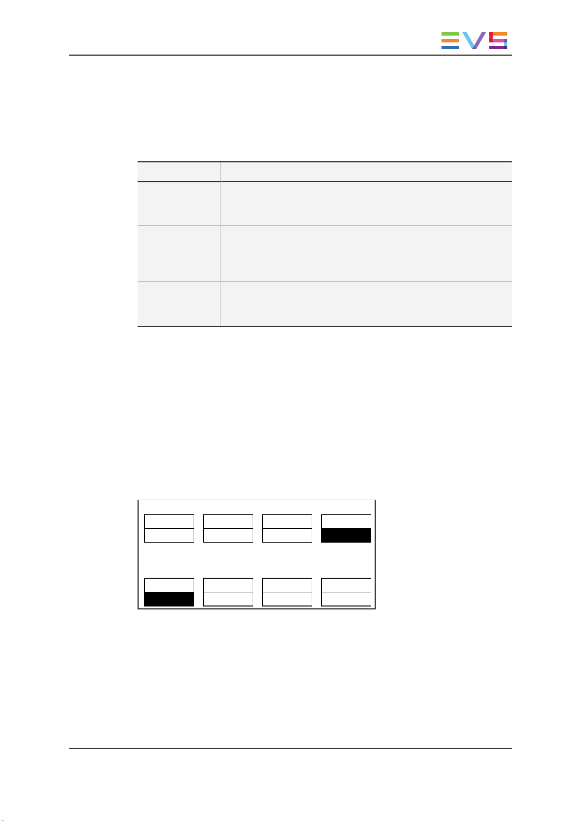
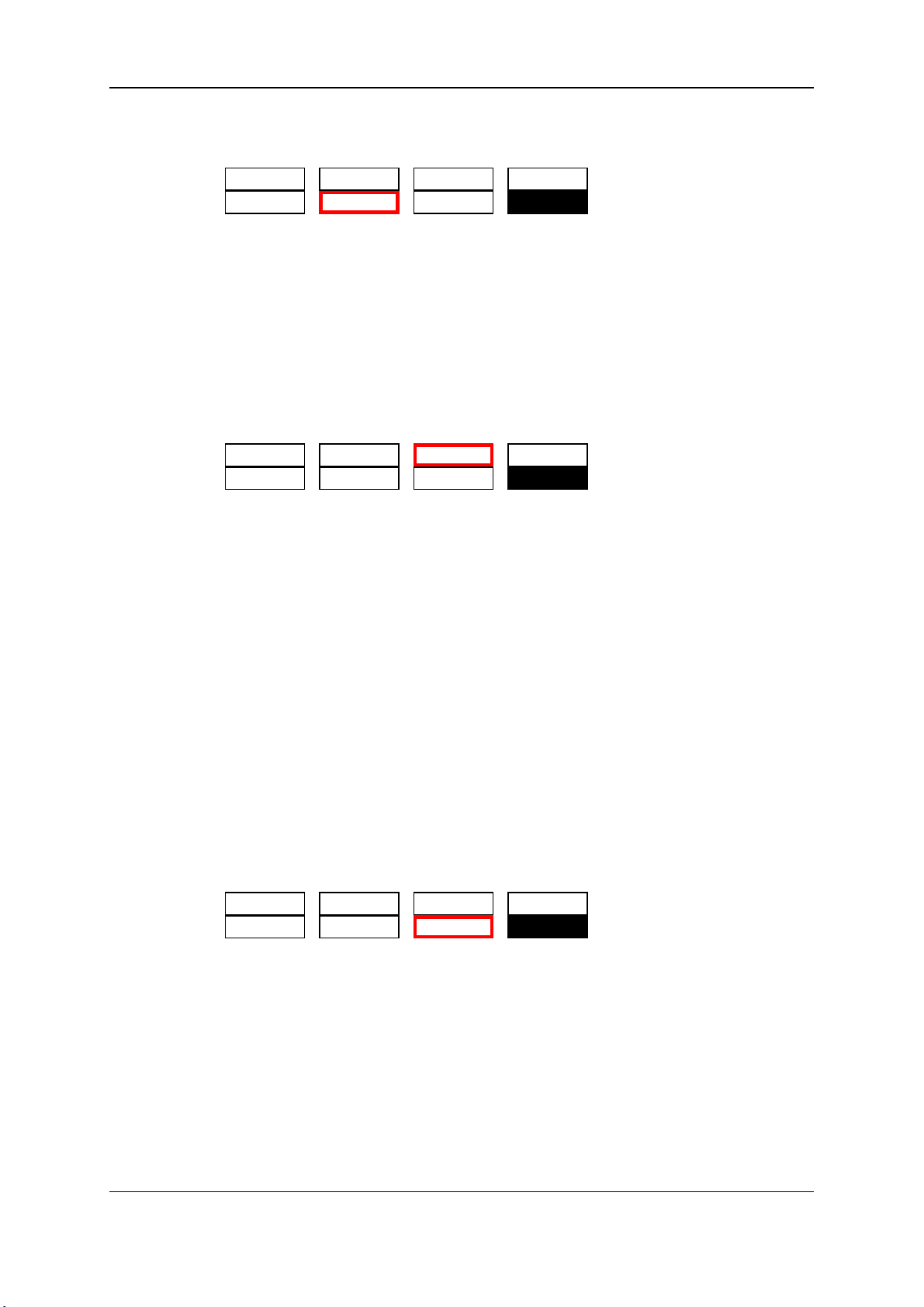
2.2.4. Soft Keys and LCD Display
The soft keys have primary and secondary functions andare divided into upper and lower
sections.
The LCD display is divided into two menus.
• To access the secondary functions in the operational menu (A’ to D’), press the
SHIFT button.
• To access the secondary menu, press MENU from the remote controller. This menu
is used to define settings that do not require regular changes, without havingto return
to the Setup menu.
• To return to the Operational menu, press the MENU key again.
• To return to the Main menu in Multicam, press SHIFT+MENU.
8 2. Working Interfaces
Page 19

OPERATION MANUAL Multicam LSM 11.02
2.2.5. Jog Dial
The jog dial allows the operatorto pass into Search mode andthus to choose exactly the
Short OUT or Short IN image.
Move the jog dial clockwise to search forward and move it counter-clockwise to search
backwards. One revolution of the jog dial will produce a jump of approximately 35frames.
When using the Fast mode, this numberis multiplied by a factor defined in the Setup
menu.
Note
The jog dial is also used to:
• Set parameters in the Setup menu.
• Browse inside the clip database, the cue points or the current playlist. Refer
to the explanation of the Browsefunction for more details.
The jog dial is active at all times when the system is in Play andRecordmodes.
2.2.6. Lever
The lever is used to start a play or to modify the slow motion speed. Its run can be of two
different types depending on the lever mode. In standard mode, the lever run goes from 0
up to 100%.
Different ranges are availableto play material from –400% to 400% using the 'Second
lever range' parameter in the Operational Setup menu (p.9.1 F5).
To access this second speed range, press SHIFT+Lever on the remote controller.
Note
When SD SUPER MOTION material is loaded on the primary channel, the lever
range has a larger, flat step at 33%.
In HD SUPER MOTION mode, the step is at 33% or 50% depending on the
camera.
The lever is also used to adjust speed, effect type, and duration in Playlist Edit mode.
2. Working Interfaces 9
Page 20

EVS Broadcast Equipment S.A. Issue 11.02.A July2013
2.2.7. Keyboard Locking
You can lock a remote keyboard at any time to protect it against accidental changes, for
example to prevent interruption of a play operation on an unattended device. Only the
locked device is affected, other remotes will stay fully operational.
How to Lock a Remote Panel
To lock a remote, press the CLEAR key. Then, within 2 seconds, press the MENU key
on the keyboard.
The following confirmation message is displayed:
███████████████████████████████████████
Do you really want to lock this remote?
[Menu] : Cancel
[Enter]: Confirm
███████████████████████████████████████
Press ENTER to confirm the locking of the remote.When a remote is locked:
◦ The CLEAR and MENU keys, used for unlocking, areflashinggreen.
◦ All other keys arecontinuously lighting red.
◦ The jog brake is activated.
◦ All keys, the lever and the jog beep if pressed or operated, except the CLEAR and
MENU keys, used for unlocking.
In addition, the following message is displayed in the middle of the current screen:
Msg: Clear+Menu to unlock the remote
How to Unlock a Remote Panel
To unlock the remote, press again the CLEAR key then, within 2 seconds, the MENU
key. The remote goes back to its operating mode.
10 2. Working Interfaces
Page 21

OPERATION MANUAL Multicam LSM 11.02
2.3. Remote Panel Operations
2.3.1. Main Menu
Introduction
After the boot sequence of the Multicam system, the LCD screen of the Remote Panel
will display the Main menu:
2Rec 4PlayServerVer:11.00.xx
F1: 1 RemoteF6: Exit
F2: 2 RemotesF7: Clear all clips
F3: 3 RemotesF8: Stop Record
F4: 4 RemotesF9: Fill Playlist
F5: Char. On/OffF0: Technical setup
Split Paint Target Setup
1PGM+PRV 2 PGM
The Main menuhas special function key operations as shown above, as well as the “soft”
keys options to enter 1PGM, 1PGM+PRV, 2PGM, or 3PGM modes (if available)and to
enter the Setup menu to configure your remote controller or to add special functions to
your application.
Note
If 2 channels are available for the first Remote Panel, the B key will display 2
PGM. If 3 channels are available, the B key will display 3 PGM.
Returning to the Main Menu
From any section of the application, except Playlist mode, press SHIFT+MENU on the
first Remote Control panel to return to the main menu.
Function Keys in the Main Menu
Select the correspondingFunction key (F_ key), and then press ENTER to validate the
selection.
Function Key Use
F1 to F4 If desired, the Multicam system can be run using 1, 2, 3 or 4 EVS
Remote Panels. Depending on the number of play channels
available in the current configuration, 1-, 2-, 3- or 4- Remote
modes will be available from the main menu.
F1: 1 Remote One Remote Panel is used in the configuration
2. Working Interfaces 11
Page 22

EVS Broadcast Equipment S.A. Issue 11.02.A July2013
Function Key Use
F2: 2 Remotes Two Remote Panels areused in the configuration.
If 4 play channels are available, when selecting the 2 Remotes
mode, the operator can choose between two configurations:
• 2 play channels for each remote:
In this configuration, each Remote Panel can select
PGM+PRV or 2PGM mode. Each Remote Panel can
manage video transitions (cut, mix, wipe) in PGM+PRV and
playlist modes.
• 3 play channels for the 1stremote and 1 play channel for the
second remote.
In this configuration, the 1stremote can select PGM+PRV or
3PGM modeand can manage video transitions. The 2
nd
remote is forced to 1PGM mode and can only handle cut
transitions.
F3: 3 Remotes Three Remote Panels are used in the configuration.
F4: 4 Remotes Four Remote Panels are used in the configuration.
F5: Char. On/Off Enables or disables the on-screen display (Timecode, Clip ID…)
on the output monitors.
F6: Exit Exits the Multicam software and returns to the EVS Menu.
F7: Clear all clips Clears all clips. All clips will be lost. A confirmation of this
command is required.
For more informationto this action. "Deleting Clips" on page 57.
Note: This command is not similar to the Clear Video Disks from
the Maintenance menu. If you wish to refresh completely the
server, i.e. to clearall clips including the protected ones, you
need to use Clear Video Disks rather than Clearall clips.
F8: Stop Record Stops the record. The REC key will go off andthe F8 function
key is now used to restart the record.
F9: Fill Playlist «Dump» feature which allows all clips to be «dumped»at the end
of the current playlist. This allows the operator to save all
material to tape, as a backup feature after a show is complete.
You can select in the Setup menu which camera angles have to
be included in the Fill Playlist function.
If your clips are currently connected to anotherserveron the
network, the clips from that serverwill be added to your current
playlist.
Make sure that the playlist you have selected is an empty one.
This function will appendthe clips at the end of an existing
playlist.
F0: Technical
Gives access to the technical setup menu.
setup
12 2. Working Interfaces
Page 23

OPERATION MANUAL Multicam LSM 11.02
Warning
In orderto guarantee the validity of data and clips previously saved, it is advised
to properly exit the application by pressing ALT+Q and ENTER from the
keyboard, or F6 and then ENTER from the Remote Panel. Do not turnoff the
system while the application is running.
2.3.2. Function of the Small Keys
MENU
This function allows the operator to gain access to the secondary menu.
SHIFT+MENU on the Remote gains access to the main menu.
Also usedas an ESCAPE key to cancel some options and messages.
CLEAR
This function clears the IN / OUT/ playlist / CLIPS / CUE points.
Note
• To clearone CUE point, recall the desired cue point and press
CLEAR+MARK key.
• To clearall cues: when current picture is not a CUE point, press
CLEAR+MARK key. A messageappears to confirm the command.
ENTER
This function appends clip(s) at the endof the current playlist. This is also used to confirm
saving of clips, and validate various options and messages.
2.3.3. Function of the Operational Block 1 Keys
Loop
It enables the internal Loop mode. The button will flash red in this mode and “LOOP” will
appear on the OSD of the output monitors. When the user selects the Loop mode, the loop
has to be cabledfrom the HD/SD “clean” output of PGM1 to the Loop In connector.
The loopis performed on the audio andvideo components of the PGM1 output, or on the
video only, depending on the Internal Loop parameter of the Operational Setup menu,
(p.9.2 F6). In audio embedded, the audiois also looped, whatever the value defined for the
Internal Loop parameter.
To leave the loop mode, you need to press SHIFT+LOOP again.
2. Working Interfaces 13
Page 24

EVS Broadcast Equipment S.A. Issue 11.02.A July2013
Note
By default, users have to connect the clean SDI output to the Loop In connector
given that the OSD of the output monitors are not disabled. If users want to use
the output monitor with characters out, they have to start the Multicam
application with the followingparameter : /LOOP_SDI_MON.
This is very useful to “consolidate” effects and edits, or adding live sound or music or
voice to previously recordedmaterial when only the video is looped back into the server.
Note
When playing back at 200% in loop mode, then replaying the looped sequence
at 50%, you can obtain a “film effect”.
PLST
This function is not active if the current playlist is empty. If the current playlist is not
empty, pressing PLST once enters the Playlist Edit mode.
• Pressing PLST from the Playlist Edit mode enters the Playlist Playout mode.
• Pressing PLST from the Playlist Playout mode re-cues the playlist to its beginning.
• Pressing 3 times PLST will always cue up the playlist ready to roll.
To play back a playlist that has been cued, press the PLAY button and it will roll at the
preset speeds.
Insert
This function inserts a clip before or after (dependingon the Setup menu) the current
position inside the playlist.
Browse
When a clip is loaded on the primary channel, pressing the BROWSE key allows the
operator to browse inside all local clips of the database by turningthe jog dial.
When a cue point exists for the current picture on the primary channel (theCUE button
lights red), pressing the BROWSE key allows the operator to browse through all existing
cue points by turning the jog dial.
When the current picture on the primary channel is neither a clip nor a cue point, or if the
operator is in Playlist mode, pressing the BROWSE key allows him to browse inside the
clips of the current playlist by turning the jog dial.
Goto IN
When you are in CLIP mode, this key combination enables the operatorto go to IN / OUT
points of clips, instantly.
14 2. Working Interfaces
Page 25

OPERATION MANUAL Multicam LSM 11.02
IN
This function defines the IN point of a clip. The key will light differently dependingon the
following situations:
• Green key The key lights green if an IN point exists but is not the image you see.
• Red key The key lights red if the on-air image is at this IN point. This point can be
entered while recording.
• Flashing (greenor red) key In Split Audio mode, this key can be flashing green or
flashing red. "Using the Split Audio Mode" on page 109for more details.
• During a Replace operation on a playlist, this key will flash red if trying to insert an IN
marker on a transition, as this is not allowed.
• During an Extend operation on a timeline, this key will flash red until you jog. At that
time, it will flash green until the operationis confirmed using the CAM D key.
Goto OUT
When you are in CLIP mode, this key combination enables the operatorto go to IN / OUT
points of clips, instantly.
OUT
This function defines the OUT point of a clip. This operates similarly to the IN button.
Modification of Clip IN / OUT Points
Select the clip that you wish to modify, use the jog dial to position the material at the new
IN or OUT point, andre-mark the IN or OUT point(s) as required.
Warning
When IN/OUT points are set and a clip is saved, the system automatically
write-protects a user definable length of material before andafter the IN/OUT
points respectively. These are referredto as the guardbands. Their duration can
be set with the Default clip duration parameter in the Operational Setupmenu
(p.2.2 F2) as required.
2. Working Interfaces 15
Page 26

EVS Broadcast Equipment S.A. Issue 11.02.A July2013
Lever
This function is used to perform slow motionfrom 0 to 100% and to playback material from
100to + 100% or from 200 to + 200% when Secondary Lever range is selected. The lever
has a continuous, linearrange, except when Super Motion material is loaded on the
primary channel. In this case, there is a “flat step”at 33% (SD SuperMotion) or 50% (HD
Super Motion) to help the operator locating easily the ideal playback speed.
Warning
When playing Super Motion material in slow motion, to obtain the smoothest
replay, it is important that the replay speed is exactly the ideal slow motion
speed, i.e. 33% for SD Super Motion or 50% for HD Super Motion. If the replay
speed is slightly off these ideal values, movements might appearstaggered.
These ideal speeds can also be called directly by pressing the PLAY button
when the current element is SuperMotion. ThePGM speed andVar Max modes
can also beused to facilitate this. See Chapter6 ‘PGM-PRV Mode’ on page26
for a description on these modes.
TAKE
• In PGM+PRV mode, pressing this button swaps cameras on PGM and PRV monitors
• In Multi-PGM mode, pressing this button toggles between CAM selection and PGM
selection modes.
• In 2 PGM mode, when both PGMs are selected on the Remote Panel, pressing this
button swaps the content loaded on PGM1 with the one loaded on PGM2 and viceversa.
• In Playlist Edit mode, pressing this button inserts the clip loadedon the PRV channel
into current playlist.
2.3.4. Function of the Operational Block 2 Keys
Network
This function gives access to the clips and/or records trains of other machines on the
network. After the selection of the machine, the way of selecting clips and camera angles
is similar to clips selection on the local LSM system. "Operation on XNet Network" on
page 165.
16 2. Working Interfaces
Page 27

OPERATION MANUAL Multicam LSM 11.02
PLAY
This function initiates a forward motion. It can also be usedto start playback of playlists
andclips (refer to PLST command).
When PgmSpd/Var Max is OFF, the default playback speed whenpressing the PLAY key
is 100% for standard pictures, 33% for Super Motion pictures with a TripleSpeed camera
(SD), and 50% for SuperMotion pictures with a Double Speed camera (HD),.
When PgmSpd/Var Max is ON, the value defined in the Operational Setup menu for the
PGM Speed/Var max parameter (p.9.1 F3) is used.
Goto TC
This function allows you to jumpto a given timecode in the loaded train or clip.
How to Go to a Given Timecode
To go to a given timecode, proceed as follows:
1. Press SHIFT+GOTO TC key on the Remote.
The GOTO TC window is displayed on the Remote Panel :
Go to TC xx:xx:xx:xx
[Menu] : Cancel
[Enter] : Go to TC
Reset FromDate To Date
Return LTC
2. To specify a date from which the search should be executed, press SHIFT+C, enter
the date in the format dd/mm/yy, using the F1 to F10 keys, and press ENTER on the
Remote.
3. To specify a date up to which the search shouldbe executed, press SHIFT+D and
enter the date in the format dd/mm/yy using the F1 to F10 keys and press ENTER on
the Remote.
4. To specify whether to go to a LTC, USER timecode or any of both (LTC/USER),
press C until the requested timecode type is displayed.
5. Enter the requested timecode using the function keys F1 to F10.
Eight digits: hh:mm:ss;ff (f=frame)are displayed on the LCD screenof the Remote.
◦ If you enterall 8 digits, Multicam will automatically go to the required timecode.
◦ If you enterless than8 digits (when the last digits are zeros), press ENTER on the
Remote to validate the entry and reach the requested timecode.
Once you have entered the Goto TC, you can observe it has been correctly entered on
the display of the Remote LCD screen andon the output monitor. This Timecode
display appears in the centre of the LCD display, just above the menu options.
6. Press ENTER on the Remote.
2. Working Interfaces 17
Page 28

EVS Broadcast Equipment S.A. Issue 11.02.A July2013
If the timecode is from the LTC table, it will be displayed in white on the output monitor.
If the timecode is from the USER TC table, it will be displayed in yellow onthe output
monitor.
If nothing happens after confirming the TC entry with ENTER, this means that the field
corresponding to the selected Timecode does not exist on the disk any longer.
To exit the GOTO TC function at any time, press the MENU key.
Last Cue
This function re-cues the EVS server to previous cue point relative to the current timecode
position. Each time the Last Cue button is pressed, the EVS server re-cues to the
previous cue, etc. Whenrecalling a cue point, the cue number appears in the upperleft
corner of the OSD if this option is enabled with the Cue number on OSD parameter in the
Operational Setup menu (p.1.1 F1)
Fast Jog
When selected, this option enables fast picture search: the actual speed of this fast jog is
adjustable in the Setup menu. Starting a play or returning to E2E mode resets the Fast Jog
mode.
Warning
The jog dial is active at all times when the system is in play & record. The brake
is automatically turned on when startinga playback with the PLAY key or with
the lever, or whenreturning to E2E mode with the RECORD button.
Mark
This function marks up to 256 cues that can be markedwhile recording or playing. The
cues are marked on the LIVE or PLAYBACK program depending on the valueset in the
Setup menu. When the operatorhas marked 256 cues, the next onewill overwrite the
oldest one.
Return
Inside a clip, press the RETURN key to remain on the same picture, but inside the record
train instead of the clip (if that picture still exists in the record train). This is useful when a
clip is too tight and you want to use material beyondthe current IN or OUT point.
RECORD
This key lights red when the system is recording. Pressing this key brings the system in
E/E (“live”) mode, and starts the record if necessary (depending on the settings of the
Setup menu). The E/E mode is actually playingpictures already recorded by the system,
andhas a delay of 3 frames compared to the live source, on all audio and video tracks.
18 2. Working Interfaces
Page 29

OPERATION MANUAL Multicam LSM 11.02
Page
Use this key to select a new clips page. After pressing the SHIFT+PAGE key, you must
press a F_ key to select the corresponding page(1 to 10).
PRVCTL
This function enables/disables the Preview Control mode.
2.3.5. Rebooting the System from the Remote Panel
«Hard Reboot»
In the event that the system needs to be rebooted, the process can be accomplished from
the Remote Panel. Keep in mind that doing this while Multicam is running will of course
force the Multicam application to close abruptly, andup to 1 minute of the material being
recorded and not clipped could be lost.
To reboot, press the following key sequence,
Between step 3 and step 4, the RECORD button will flash GREEN and the PAGE button
will flash RED. Hitting the PAGE button will reboot the system. Hitting the RECORD
button will return to normal operation.
«Soft Reboot» from the Keyboard
It is also possible to run a «soft reboot» which will exit the software and returnthe user to
the EVS Menu. Here, the software can be selected and entered again without having to
reboot the entire system. When running the followingprocedure, the system will
automatically save all recorded material (record trains, clips, playlists) upon exit.
Hit ALT+Q on the keyboardor press F6 from the mainMenu, and confirm with ENTER or
cancel with ESC. You will exit the Multicam software and go back to the EVS Menu.
2. Working Interfaces 19
Page 30

EVS Broadcast Equipment S.A. Issue 11.02.A July2013
3. Control Modes
3.1. Live, Search or Playback Mode
Multicam can be set in three different basic modes, depending on commands used:
Live (E2E) Mode
This mode selected at start-up can also be selected by pushing the RECORD key.
Multicam records the input signal and plays it at the same time on the program output.
Search Mode
This mode is selected by moving the jog dial.
In this mode, the operator has the opportunity to search for an image, in order to define cue
points or clips. Moving the command knob clockwise will force Multicam to search
forward, moving the command knob counter-clockwise will force it to search backwards.
The most important thing to note is that Multicam never stops recording while searching.
Playback Mode
Moving the lever or pressing the PLAY key selects this last mode.
Multicam plays the incoming signal delayed, a clip or a playlist, in slow motion and of
course continues to recordthe incomingsignal on disks.
As soon as the lever is moved, Multicam starts playing back from the current picture. The
playback speedis defined by the lever position. This is used to start the playback of a
normal slow motion, as well as the playback of a clip or a playlist. During playback, the
system never stops recording
Note
Each operation on the Remote Panel with the control jog or lever will be
associated to the Search orPlayback mode respectively.
20 3. Control Modes
Page 31

OPERATION MANUAL Multicam LSM 11.02
3.2. 1PGM+PRV Mode
3.2.1. 1PGM+PRV Mode
Introduction
Multicam has two modes for its basic operation, 1PRV+PGM and Multi PGM:
• The 1PGM+PRV mode is more powerful as it allows interaction between all outputs.
Synchronized replays can be rolled andchained between the cameras with either a
mix, a wipe, or a cut between them.
• The Multi PGM mode is more basic but gives the operator independent control of all
outputs. These outputs can be controlled together (such as jogging back to a certain
action on all outputs) or individually (eitherPGM 1, 2, or 3).
How to Enter the PGM+PRV Mode
To enter the 1PGM+PRV mode, press A from the Main menu. The Remote Panel will then
display the followingscreen:
PGM1 CAM A *PRV1* CAM B
Aud.Met. PgmSpd Sort->TC PostRoll
Mix Sw to IN Search Pref
P.1 B.1 Clips: LOCAL Records: LOCAL
PL 11: <
Msg
Rst Cam Local Sync Prv 2nd CTRL
Cam A Cam B Cam C Cam D
At least 2 playback channels must be available to run this configuration.
This mode allows the operator to make replays with/or without transition effects between
all outputs. A string of replays can be put together andplayed back at the operator’s
discretion.
The LCD display is divided in two menus controlled by soft keys (A, B, C, D). To gain
access to the upper menu, press MENU from the Remote Panel.
3. Control Modes 21
Page 32

EVS Broadcast Equipment S.A. Issue 11.02.A July2013
3.2.2. 1PGM+PRV Primary Menu Controls
Introduction
The primary menu in 1PGM+PRV mode, illustrated below, gives access to the functions
detailed in the following paragraphs:
Rst Cam Local Sync Prv 2nd CTRL
Cam A Cam B Cam C Cam D
CAM A / B / C / D
Rst Cam Local Sync Prv 2nd CTRL
Cam A Cam B Cam C Cam D
If PRV CTL is 'OFF', select the camera to assign to the PGM output. This camera key
will be highlighted in the menu.
If PRV CTL is 'ON', select the camera to assign to the PRV output. This camera key will
be highlightedin the menu.
Note
In 5CAM configuration (5 recorder channels and 1 player channel) or when
loading a clip where CAM E or F exists, the operational menu will display:
Rst Cam Local Sync Prv 2nd CTRL
Cam A Cam B Cam C --->
By pressing the D key (--->), the operator has access to the D, E and F
cameras. The operation menu becomes:
Rst Cam Local Sync Prv 2nd CTRL
Cam D Cam E Cam F <---
Press the D key (<---) to return to CAM A, B, andC selection.
Rst Cam
Rst Cam Local Sync Prv 2nd CTRL
Cam A Cam B Cam C Cam D
This function restores the position of cameras on the active channels: CAM A on PGM1,
CAM B on PRV.
Note
When a clip/playlist is loaded on a channel, switching back to Live mode will
recall the record train, which was last used on that output. This avoids too
frequent uses of the RstCam function.
22 3. Control Modes
Page 33

OPERATION MANUAL Multicam LSM 11.02
Local
Rst Cam Local Sync Prv 2nd CTRL
Cam A Cam B Cam C Cam D
This function allows the user to reconnect to the local LSM after having accessed distant
clips or record trains. Thefunction is highlighted whenthe user is connected to both clips
andrecord trains on the local LSM. It is displayed only on Master/Server LSMs when they
areconnected to the SDTI network.
Sync Prv
Rst Cam Local Sync Prv 2nd CTRL
Cam A Cam B Cam C Cam D
This option allows the user to synchronize the PRV with the timecode and speed of the
PGM output. This function is not available with remote record trains.
2nd CTRL
Rst Cam Local Sync Prv 2nd CTRL
Cam A Cam B Cam C Cam D
This function allows the operator to swap the control of one or several play channels
between the EVS Remote and a third-party controller. Both controllers receive
permanently the status of the channel(s), but only one controller at a time is ableto
actually control a channel. The secondary controllers are defined in page T2.2 of the
Technical Setupmenu.
Press this function to enter the 2ndCTRL menu, select the channels that you want to
pass to the secondary controllerby pressing the corresponding A or B key, then press D
(DONE) to validate your selection. Do the same to bring the control of a channel back to
the EVS remote.
See section "Secondary Controller" on page 32.
3.2.3. 1PGM+PRV Secondary Menu Controls
Introduction
The secondary menu in 1PGM+PRV mode, illustrated below, gives access to the
functions detailed in the followingparagraphs:
Aud.Met. PgmSpd Sort->TC PostRoll
Mix. Sw to IN Search Pref
3. Control Modes 23
Page 34

EVS Broadcast Equipment S.A. Issue 11.02.A July2013
Mix / Wipe L>R / Wipe R>L / Wipe U>D / Wipe D>U / Cut
Aud.Met. PgmSpd Sort->TC PostRoll
Mix. Sw to IN Search Pref
These options determine the transition effect that will occur between the PGM and PRV
pictures. The mix, wipe andcut are on the same location. Pressing this button will browse
through these effects, showing the active one on the LCD menu. Please refer to Setup
menu to select the duration of the transition effect.
PgmSpd / VarMax
Aud.Met. PgmSpd Sort->TC PostRoll
Mix. Sw to IN Search Pref
Pressing PgmSpd once enables the Program Speedmode and highlights this function on
the LCD. Pressing the key once moreenables the VarMax modeand highlights this
function on the LCD. The PLAY key is flashing red while either of these modes is
enabled.
• Program Speed mode: In this mode, only two speed values are available from the
lever: 0% when the lever is in the lower position, or the speeddefined in the
Operational Setup menu (p.9.1 F3) for any other position of the lever.
• VarMax mode: the speedrange defined by the lever is limited between 0% and the
speed valuedefined in the Operational Setup menu (p.9.1 F3).
Sw To In
Aud.Met. PgmSpd Sort->TC PostRoll
Mix. Sw to IN Search Pref
When this function is enabled (highlighted), a camerachange will cause a jump to the
corresponding IN point if existing. It will switch in Sync if no IN point exists for the current
element, orif SwtoIN is 'OFF'.
See section "Synchronization Mode(Switch To In)" on page 31 for more information on
this option.
Pref
Aud.Met. PgmSpd Sort->TC PostRoll
Mix. Sw to IN Search Pref
Selecting this function enables the Preference mode.
See section "Preference Mode (PREF)" on page 31 for more inforamtionon this option.
24 3. Control Modes
Page 35
OPERATION MANUAL Multicam LSM 11.02
Aud.Met.
Aud.Met. PgmSpd Sort->TC PostRoll
Mix. Sw to IN Search Pref
This option enables/disables the display of audiometers for all channels using the OSD of
the output monitors.
Post-Roll
Aud.Met. PgmSpd Sort->TC PostRoll
Mix. Sw to IN Search Pref
When the post-roll modeis enabled, that function is highlighted on the LCD and a “P”
appears onthe OSD of the output monitors.
When the user exits Multicam with the post-roll mode on, this mode will still be enabled
when Multicam is restarted.
The post-roll mode works as follows depending on the element played:
• Whena clip is played, it will not stop on the Short OUT point, but will continueto play
through the Short OUT point by the post-roll duration definedin the Setup Menu.
• Whena record train is played, the same will happen if the Recordtrains OUTs
parameter is set to “Freeze” in the Operational Setup menu (p.2.3 F1).
• Whena playlist is played, the post-roll will apply only to the last clip of the playlist.
Sort->TC
Aud.Met. PgmSpd Sort->TC PostRoll
Mix. Sw to IN Search Pref
This function allows the operator to search for all clips that contain a particular timecode.
See section "Remote Panel Functions" on page38 for more informationon this function.
Search
Aud.Met. PgmSpd Sort->TC PostRoll
Mix. Sw to IN Search Pref
This function allows the operator to search the database using keywords and ranking.
"Keyword Management" onpage 148.
To return to the operational menu, press the MENU key from the Remote Panel.
3. Control Modes 25
Page 36

EVS Broadcast Equipment S.A. Issue 11.02.A July2013
3.2.4. Full Control and Lever Control
You control both PGM and PRV when the PRV CTL key is not active.
Once you select PRV CTL, you gain control on the PRV channel with the jog dial and
most keys, while the lever and the PLAY key control the PGM output. At this point,
selecting clips will call them up on the PRV channel.
Activating both the PRV CTL and the SW to IN functions allows the operator to auto-chain
cameras from the same IN point.
Let's say an IN point has been marked, and you activate the PRV CTL and sets to ON the
SW to IN option: Theslow motionof one camera can be started from this IN point. The
operator selects another camera in the PRV output and, via the TAKE button, can autochain cameras from the same IN point on the PGM output.
3.3. Multi PGM Mode
3.3.1. Multi PGM Overview
Introduction
Multicam has two modes for its basic operation, 1PRV+PGM and Multi PGM:
• The 1PGM+PRV mode is more powerful as it allows interaction between all outputs.
Synchronized replays can be rolled andchained between the cameras with either a
mix, a wipe, or a cut between them.
• The Multi PGM mode is more basic but gives the operator independent control of all
outputs. These outputs can be controlled together (such as jogging back to a certain
action on all outputs) or individually (eitherPGM 1, 2, or 3).
26 3. Control Modes
Page 37

OPERATION MANUAL Multicam LSM 11.02
How to Enter the Multi-PGM Mode
To enter the Multi PGM mode, press B from the Main menu. This button is labeled
'1PGM', '2PGM', or '3PGM' according to your system configuration.
The Remote Panel will then display the following screen:
PGM1 CAM A *PGM2* CAM B PGM3 CAM C
Aud.Met. PgmSpd Sort->TC PostRoll
Sw to IN Search Pref
P.1 B.1 Clips: LOCAL Records: LOCAL
PL 11: <
Msg:
Rst Cam Local Sync To 2nd CTRL
PGM 1 PGM 2 PGM 3 TOGGLE
The LCD display is divided in two menus controlled by soft keys (A, B, C, D). To gain
access to the upper menu, press MENU from the Remote Panel.
3.3.2. Multi PGM Primary Menu Controls
Introduction
The primary menu in Multi PGM mode, illustrated below, gives access to the functions
detailed in the following paragraphs:
Rst Cam Local Sync To 2nd CTRL
PGM 1 PGM 2 PGM 3 TOGGLE
Rst Cam
Rst Cam Local Sync To 2nd CTRL
PGM 1 PGM 2 PGM 3 TOGGLE
This function restores the position of cameras on the active channels: CAMA on PGM1,
CAMB on PGM2, etc.
Note
When a clip/playlist is loaded on a channel, switching back to Live mode will
recall the record train, which was last used on that output. This avoids too
frequent uses of the RstCam function.
3. Control Modes 27
Page 38
EVS Broadcast Equipment S.A. Issue 11.02.A July2013
Sync To
Rst Cam Local Sync To 2nd CTRL
PGM 1 PGM 2 PGM 3 TOGGLE
This button allows you to synchronize the selected PGM in use with another one. Press
this button and then select the PGM to be usedas a reference. This function is not
available with network trains.
2nd CTRL
Rst Cam Local Sync To 2nd CTRL
PGM 1 PGM 2 PGM 3 TOGGLE
This function allows the operator to swap the control of one or several play channels
between the EVS Remote and a third-party controller. Both controllers receive
permanently the status of the channel(s), but only one controller at a time is ableto
actually control a channel. The secondary controllers are defined in page T2.2 of the
Technical Setupmenu.
Press this function to enter the 2nd CTRL menu, select the channels that you want to
pass to the secondary controllerby pressing the corresponding A, B, or C key, then press
D (DONE) to validate your selection. Do the same to bring the control of a channel back to
the EVS remote.
Note
The 1PGM mode is a simplified version of the 2 or 3PGM modes. The
operational menuhas less functions:
Local 2nd CTRL
CAM A CAM B CAMC CAM D
Additionaly the user does not need to select a channel to enable or disablethe
secondary controller. Since there is only 1 channel available in this mode, the
operator only has to press SHIFT+D to swap the control between the secondary
controller and the EVS Remote.
Toggle / All
Rst Cam Local Sync To 2nd CTRL
PGM 1 PGM 2 PGM 3 TOGGLE
The Toggle function is only available in 3PGM mode:
• Toggle OFF: Selecting an output channel results in controlling that channel and
disables the control on others.
• Toggle ON: Selecting a channel will alternatively enable/disablethe control over that
channel without changingthe control on the others.
• All: This enables the control on all channels.
28 3. Control Modes
Page 39

OPERATION MANUAL Multicam LSM 11.02
How to Assign a Camera to a Channel
In Multi PGM mode, to changethe current camera on each PGM, proceed as follows:
1. In the primary menu, select the PGM to which you want to change the current camera.
The TAKE key at the bottom of the remote is thenlighting red.
2. Press the TAKE key. It lights green and the menu on the LCD display changes to let
you select the desired camera.
Rst Cam Local
CAM A CAM B CAMC CAM D
3. Press the camerayou want to associate to the selected PGM.
4. Press TAKE again to return to the PGM selection menu.
Playlist Conditional Mode
This mode is only available in 2PGM and 3PGM modes. It allows the operator to load and
control several playlists simultaneously from the same Remote Panel, orto load a playlist
on one channel while performing otheroperations on the otherchannel(s). To use this
mode, the Load Playlist parameter of the Operational Setup menu must be set to
Conditional (p.3.3 F2).
To use this mode, select one channel (for example PGM1), andpress the PLST key one,
two or three times to enter the PLST EDIT or the PLST DIFF mode (refer to the “Playlist
Management” Section of this manual for details about these modes). You can notice that
the TAKE key lights green. Pressing the TAKE key will allow the operator to return to the
PGM selection menu, and select another PGM channel where he can start a replay, load a
clip oranother playlist, etc.
In this mode, if the operator selects a PGM channel where a playlist is loaded and presses
the TAKE key, he will enter again the PLST EDIT or PLST DIFF mode.
When playlists are loaded on all channels currently controlled by the operatorin Multi
PGM mode, the TAKE key lights red. If the TAKE key is pressed, the remote will enter a
specific PLST DIFF mode, where the operator can control several playlists
simultaneously, and browse them or roll them in sync. NEXT and SKIP functions are also
available and will apply on all controlled playlists. The TAKE button will not light red if one
of the controlled channels does not contain a playlist.
3. Control Modes 29
Page 40

EVS Broadcast Equipment S.A. Issue 11.02.A July2013
Practical example
The operator builds a playlist with Fills and another playlist with Keys. He sets the Playlist
Load parameterto Conditional in the setup menu, thenenters the 2PGM mode, selects
the Fills playlist as current playlist, presses A to gain control on PGM1, presses PLST two
or threetimes to enter the PLST DIFF modeand cue upthe Fills playlist to its 1st clip.
Then he presses the TAKE key to returnto the PGM selection menu, selects the Keys
playlist as current playlist, presses B to gain control on PGM2, presses PLST two or three
times to enter the PLST DIFF modeand cue upthe Keys playlist to its 1st clip. Then he
presses the TAKE key to returnto the PGM selection menu, presses D to gain control on
both PGM channels, then presses TAKE to enter the PLST DIFF menu. He will see the
content of both playlists side by side on the LCD screen, and can browse them or play
them in Sync at any speed, and perform SKIP and NEXT commands as needed.
3.3.3. Multi PGM Secondary Menu Controls
The secondary menu can be called by pressing the MENU key andis similar to the
1PGM+PRV mode, except that the A function is empty since it is not possible to create a
transition between the channels in this mode.
See section "1PGM+PRV Secondary Menu Controls" on page 23 for a description of the
other functions of the secondary menu.
30 3. Control Modes
Page 41

OPERATION MANUAL Multicam LSM 11.02
3.4. Synchronization Mode (Switch To In)
The Synchronization mode allows users to define how they jump from onecamera to the
other. The Synchronization mode is available in the secondary menu from the main LCD
display, using the B soft key.
If the Synchronization mode is OFF (SW to IN is not highlighted in the secondary menu), a
request for camera change will produce a jump at the same timecode on the requested
camera. This mode allows synchronous change of camera angle.
If the synchronization modeis ON, a request for a camera change(by pressing CAM A,
CAM B, CAM C, or CAM D in the Multicam menu)will leadto a jump to a predefined
CUE IN point.
If a CUE IN point has not been previously defined, Multicam acts as in SW to IN OFF
mode (even if SW to IN ON is shown) because the system has no reference to jump to.
3.5. Preference Mode (PREF)
The Preference mode allows users to show the preferential camera angle by default when
a clip is loaded. The Preference mode is available in the secondary menu from the main
LCD display, using the D soft key.
When this optionis ON and a clip is recalled, the preferred camera will be displayed on the
main output, even if another camera angle was previously loadedon that output.
The preferred camera is the one, which was onthe primary output channel when the clip
was created.
The second preferential camera (“secondary camera”) is the one that was loaded on the
next channel when the clip was created.
In the Clip screen, the first preferential camera is indicated by a star: 111B* and the
second preferential camera is indicated by 2 dashes: 111B=.
When the preference option is disabled, the PGM output stays on the camera currently
selected when the clip is called.
3. Control Modes 31
Page 42

EVS Broadcast Equipment S.A. Issue 11.02.A July2013
3.6. Controlled and Primary Channels
Controlled Channel
A channel is "controlled" whenthe operator can control it with the jog dial. In this case, the
words "FULL CTRL" are present on the top of the OSD of the output monitor of that
channel.
Primary Channel
The primary channel is the first controlled channel. It is identified by stars around its name
on the OSD of the output monitor and on the LCD display of the Remote Panel (ex:
*PGM1*).
Examples:
• In 3PGM mode, if the operator controls PGM 2 and PGM 3, the primary channel is
PGM 2.
• In 1PGM+PRV mode with PRV CTRL OFF, the primary channel is PGM.
• In 1PGM+PRV mode with PRV CTRL ON, the primary channel is PRV.
3.7. Secondary Controller
Introduction
The 2ndCTRL function available on the Remote Panel in the main operational menu
allows the operator to swap the control of one or several play channels between the EVS
Remote and a third-party controller.
Both controllers receive permanently the status of the channel(s), but only one controller
at a time is able to actually control a channel: this is called the exclusive secondary
control mode. The secondary controllers are defined in the Operational Setup menu of the
remote (p.2.2).
32 3. Control Modes
Page 43

OPERATION MANUAL Multicam LSM 11.02
Interactions between IPDP and Multicam
When a Remote Panel and an IPDirector share the control of some PGMs in exclusive
secondary control mode, the following principles apply:
• Whena playlist/timelineis controlled by the Remote Panel on a PGM, the
playlist/timeline remains the current one when IPDirector is given the control on the
PGM.
• Whena playlist/timelineis controlled by IPDirector on a PGM, the playlist/timeline
remains the current playlist on the Remote Panel when the operator takes back the
PGM control.
• Whenseveral playlists/timelines have been controlled by IPDirector on several PGMs
andthe operator takes back the PGM control, the current playlist/timeline on the
Remote Panel is the one that was the current playlist whenthe control was given
away, in other words the current playlist/timeline does not change.
• Whenthe playlist/timeline controlled by IPDirector is not visible by the Remote Panel,
the current playlist/timeline on the Remote Panel is the onethat was the current
playlist when the control was given away, in other words the current playlist/timeline
does not change.
3. Control Modes 33
Page 44
EVS Broadcast Equipment S.A. Issue 11.02.A July2013
4. Clip Management
4.1. Introduction
4.1.1. Clip Structure
Concepts
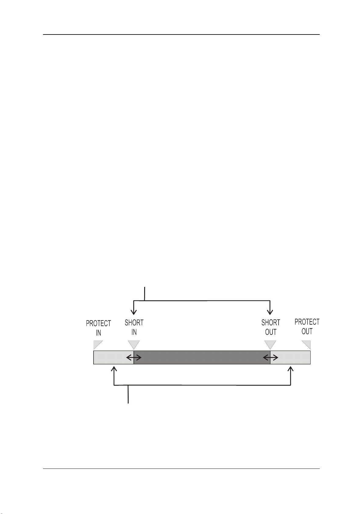
A clip is defined by Short IN andShort OUT points. When referring to Short IN and Short
OUT points, the operators usually use the terms IN point andOUT point.
When Short IN and Short OUT points are set, the system automatically write protects a
user definable length of material before andafter the Short IN/OUT points respectively,
these are referred to as the guardbands.
For this reason, the IN point before the guardbands and the OUT point after the guardband
arecalled Protect IN point and Protect OUT point.
Use of Guardbands
It is possible to trim a clip by redefining Short IN andShort OUT points.
If Short IN and Short OUT points are defined, only the fields between those two points will
be playedif the sequence is recalled(the same applies whenthe sequence is includedin a
playlist).
Fields between Protect IN andShort IN andfields between Short OUT and Protect OUT
(guardbands) can be reached with the jog. So the Short IN and Short OUT points can be
redefined.
34 4. Clip Management
Page 45

OPERATION MANUAL Multicam LSM 11.02
General Principles
Protect IN & Protect OUT points of a clip cannot be replacedby new ones.
Short IN & Short OUT points of a clip can be replaced by new ones.
Short OUT point is excluded. The clip freezes on previous field whenplaying back (with
post-roll mode disabled).
(Short) IN & OUT are always on even fields. This is automatic.
The guardband beyond the Short OUT point is created with the material available when
the operator saves the clip by pressing the selected F_ key. Therefore, this guardband can
sometimes be shorter than the valuedefined in the Setup menu.
4.1.2. Clip Numbering Hierarchy
Introduction
Multicam can store up to 900(multiplied by the number of cameras) clips and 100 playlists
in its libraries. 900 clips with up to 6 cameraangles per clip result in 5400clips on a server.
This number is displayed in the upper right window of the VGA Setup screen (SHIFT+F2
from the PC keyboard).
If you are working with XNet SDTI network, keep in mindthat the total number of clips on
the entire network is limited to 6,000or 16,000, depending on the network settings. This
number is displayed in the same area on the VGA Setup window.
4. Clip Management 35
Page 46
EVS Broadcast Equipment S.A. Issue 11.02.A July2013
Clip Hierarchy Diagram
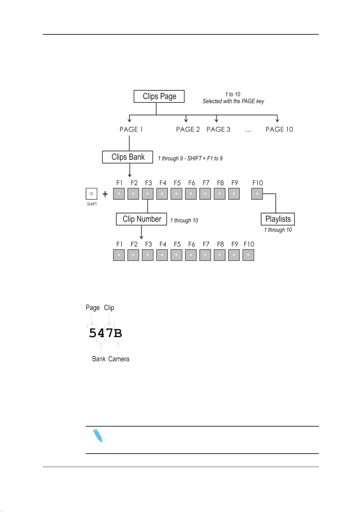
The following diagram represents the hierarchy of the Multicam clip numberingsystem.
As an example, clip number “112” is used:
Clip LSM ID
The clip numberingsystem is as follows:
In the above example, the
• “5” refers to the clip page number (1 to 10).
• “4” refers to the clip bank (1to 9)
• “7” refers to the clip number(1 to 10) inside the bank
• "B" refers to the camera name.
Note
To identify remote clips when using the XNet SDTI network, the number of the
clip is followedby the number of the machine on the network. i.e. Clip 547B/04
36 4. Clip Management
Page 47
OPERATION MANUAL Multicam LSM 11.02
4.1.3. Clip Availability on Disks
Various clip types can be distinguished depending on whether they are availableon the
disks or not. Depending on the clip availability on disks, you can perform specific actions
on the given clip or not.
Clip Available Actions
Clip on disk Clips which are protected on disks, and which have Short IN and
Short OUT points present on disks.
All the material is available on the disk.
Growing clip Clips which are protected on disks, and which have a Short IN
point, and possibly Short OUT point defined on disks.
Since the record process is still undergoing, some of the material is
already on the disk but not all of it.
Reserved clip Clips for which the position has been reserved on the SDTI
database but for which there is no Short IN and Short OUT points,
norany protect present on disks.
4.2. Clip Functions on the Remote Panel
4.2.1. Remote Panel Interface
Overview
In Clip mode, the secondary menu of the Remote Panel is different from the RecordTrain
mode:
PGM1 112A *PRV1* 112B
Push Aux Clip Sort->TC PostRoll
>Archive *** Name Cam
P.1 B.1 Clips: Local Records: Local
PL 11: < >
Msg:
Rst Cam Local Sync Prv 2nd CTRL
Cam A Cam B Cam C Cam D
Press MENU to access the secondary menu.
4. Clip Management 37
Page 48

EVS Broadcast Equipment S.A. Issue 11.02.A July2013
Secondary Menu Without Keyword File Defined
If no keywordfile is selected in the setup, the LCD display will be:
1keyword8901 2keyword8901 3keyword8901
111A
Push Aux Clip Sort->TC PostRoll
>Archive *** Search Cam
In this mode of the secondary menu, clips can still be directly recalled using the F1-F10
keys of the Remote Panel.
Secondary Menu With Keyword File Defined
If a keyword file is selected in the setup, the LCD display will be:
1keyword8901 2keyword8901 3keyword8901
F1:action_1 F6:action_6
F2:action_2 F7:action_7111A
F3:action_3 F8:action_8
F4:action_4 F9:p.01
F5:action_5 F0:Next page
Push Aux Clip Sort->TC PostRoll
>Archive *** Name Cam
In this mode of the secondary menu, the F1-F10 keys are used for keywordassignment,
andthus can nolongerbe used to recall clips. For a description of the keyword-related
functions, please refer to the “Keyword Management” Section of this manual.
The ID of the current clip appears on the end of line 3 of the LCD display.
4.2.2. Remote Panel Functions
Secondary Menu in Clip Mode
Push
Push Aux Clip Sort->TC PostRoll
>Archive *** Name Cam
The Push function allows you to easily send a copy of a clip to another machine on the
network, via the GigE network orthe SDTI network.
• If one or two default targets (push machines) are defined in the setup, the clip will be
automatically sent to these machines.
38 4. Clip Management
Page 49

OPERATION MANUAL Multicam LSM 11.02
• If no default target is defined, the list of machines available on the network will appear.
As soon as the operator selects one of them, the clip is pushed.
Depending on the push settings defined, the default targets orthe list of possible targets
submitted to you will contain EVS servers on the SDTI network and/or EVS servers on
the GigE network.
For more informationabout the Push settings, refer to the Operational Setup menu on the
Remote Panel, page7.1.
In both cases, a message appears for a few seconds on the LCD to confirm that the clip is
being pushed and indicate the clip location where it will be stored on the receiving
machine.
If the Receive Page(s) defined on the destination machineis (are) full, the operator who
tries pushing the clip is notified. While this message is being displayed, the operator can
press the MENU key at any time to return to the normal menu. Depending on the
CAM/CLIP mode selected by the D key, only the camera angles loaded on the controlled
channels are pushed (CAM mode), or all cameraangles of the clip arepushed at once
(CLIP mode).
>Archive
Push Aux Clip Sort->TC PostRoll
>Archive *** Name Cam
The Archive function allows the operator to flag a clip to place it in the archive queue of the
XFile defined in the Operational Setup menu (p.7.1 F3). The EVS Xfile is a 2U device with
2 removable hard drives, that can be connected to the XNet SDTI network. Clips can be
archived to/restored from the removable media.
This function is blinking when the clip is flagged for archiving, but has not yet been
archived. It is permanently highlighted when the archiving of the clip is completed.
Depending on the modeselected with the D key (CLIP/CAM), the >ARCHIVE flag is
assigned only to the camera angles of the clip loadedon the controlled channels (CAM
mode), or to all camera angles of the clip (CLIP mode).
Aux Clip
Push Aux Clip Sort->TC PostRoll
>Archive *** Name Cam
This function allows assigning a clip as auxiliary audio clip to the current playlist. Press
CLEAR+Aux Clip (CLEAR+SHIFT+B) to remove the current auxiliary clip. "Playlist
Management" on page69 for more details.
4. Clip Management 39
Page 50
EVS Broadcast Equipment S.A. Issue 11.02.A July2013
Ranking (***)
Push Aux Clip Sort->TC PostRoll
>Archive *** Name Cam
The Ranking function allows assigning a ranking to the current clip. Pressing several
times this key will scroll through the different values: 0 (***, not highlighted).
Depending on the modeselected with the D key (CLIP/CAM), this ranking is assigned
only to the camera angles of the clip loaded on the controlled channels (CAM mode), or to
all camera angles of the clip (CLIP mode).
If the Keywordinfo parameter of the Operational Setup menu (p.1.1 F2) is set to “Yes”, the
ranking will appear on the OSD of the output monitors when cueing up the clip.
Sort->TC
Push Aux Clip Sort->TC PostRoll
>Archive *** Name Cam
The Sort->TC function allows the operator to search the database for all clips or trains
containing a specific timecode. Press SHIFT+C again in Set TC modeto call it.
When calling this function, the timecode of the current picture is used as a default
selection. The operator can immediately perform the search or he can edit that timecode
before starting the search.
See section "Searching for Clips by Timecode" on page 65 for more information on how to
search for clips by timecode.
Set TC
The Set TC function is only available in SHIFT+B on the Sort->TC menu. It allows the
operator to restripe the timecode of a clip. "Restriping Clips" on page 63.
Depending on the modeselected with the D key (CLIP/CAM), the new timecode value is
assigned only to the camera angle of the clip loadedon the primary channel (CAM mode),
or to all cameraangles of the clip (CLIP mode).
Name
Push Aux Clip Sort->TC PostRoll
>Archive *** Name Cam
The Name function is only available if a keyword file is selected in the Setup menu. It is
used to name a clip based on available keywords. "Keyword Management" on page 148
for more details. When the Name function is selected, pressing SHIFT+C again will call
the Search function.
Search
The Search function is “hidden” behind the Name function. Press SHIFT+C again in
Name mode to call it. It allows the operatorto search the database for clips based on
keywords and ranking. "Keyword Management" on page 148 for more details.
40 4. Clip Management
Page 51

OPERATION MANUAL Multicam LSM 11.02
PostRoll
Push Aux Clip Sort->TC PostRoll
>Archive *** Name Cam
This function enables/disables the post-roll mode. "1PGM+PRV Secondary Menu
Controls" on page23 for more explanations about this mode.
Clip/Cam
Push Aux Clip Sort->TC PostRoll
>Archive *** Name Cam
Pressing the D key will toggle between CAM and CLIP modes onthe remote. Please note
that this mode on the remote and on the VGA screens is never synchronized.
• In CAM mode, the Push, Archive, Ranking assignment, Keywordassignment, and
Name functions will apply only to the cameraangles of the clip loaded on the
controlled channels.
• In CLIP mode, these functions will apply on all cameraangles of the clip.
4.3. Clip Functions on the VGA
4.3.1. VGA Interface - Clip Screen
Standard View
The navigation through the Clip screen, and the various functions available on this screen,
can be performed using the tablet and stylus, or the keyboardshortcuts.
4. Clip Management 41
Page 52

EVS Broadcast Equipment S.A. Issue 11.02.A July2013
Extended View
The extended view shows cameras A to F instead of A to D. Only 1 bank can be viewed at
a time. The switch between standard and extended view is done by pressing F5 on the
keyboard or by clicking on the “F5:VIEW” areaon the screen.
Title Bar
The Title bar contains the status information:
• Number and name of the EVS server currently selected for clips andfor record trains
(*). The name is blinking red if it is a network machine.
• Total number of clips (i.e. protects, 1 camera angle counting for 1 clip in this count).
• Total duration of all clips.
• Remaining capacity on the server (all record trains together; valid for local server
only).
Note
The abbreviated word “(Loc.)” appears next to the nameif the local machine is
currently selected for clips and/or for record trains. The clips displayed in the clip
screen belong to this machine.
42 4. Clip Management
Page 53

OPERATION MANUAL Multicam LSM 11.02
Clip Information Area
The next area is the Clip InformationArea which displays the clips of the selected page
andbank(s). Two clip banks are displayed at a time.
For each clip and camera angle, the following information is available:
Field Description
Clip ID Uniqueidentifier of the clip on the server. Ex: 111A
The clip ID is followed by the “Creating”messagewhen the clip is in
the process of being created, copiedor moved to this location.
Clip “rank” Clip rank depending on the channel on which it has been created:
• Primary (“*” next to the clip ID)
• Secondary (“=” next to the clip ID)
The clip rank informationis highlighted in blue if the clip is protected.
Clip name Name of the clip, either automatically assigned or defined by the
user.
Archive Status • If the clip ID is blinking green, the clip is flagged for archiving, but
not yet archived
• If the clip ID is permanently highlighted in green, the archivingof
the clip has been completed
Note
In the standard view (cameras A to D), if camera E and/or F exist for a particular
clip, the D-column for this clip is replaced by the mention “More Clips” on blue
background.
4.3.2. VGA Functions - Clip Screen
Function Bar
The second line of the Clip screendisplays the available functions. Each function can be
called by the correspondingF_ key of the keyboard, or by clicking with stylus & tablet on
the corresponding area on this line.
4. Clip Management 43
Page 54
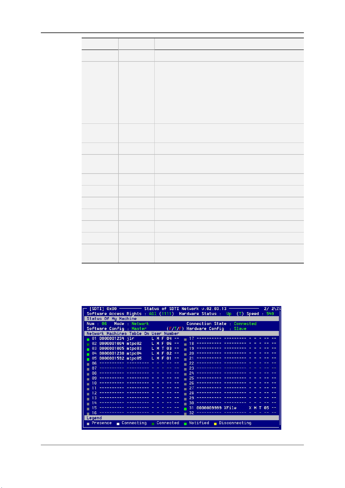
EVS Broadcast Equipment S.A. Issue 11.02.A July2013
Function Key Description
Name F1 This function is used to name a clip.
Clip/Cam F2 This function toggles betweenCLIP mode and CAM
mode.
• In CLIP mode, actions on a clip will use all available
cameras for this clip.
• In CAM mode, actions on a clip will only use the
selected camera for this clip.
Otherfunctions such as Name, Delete, Copy, Set TC,
>Archive depend on this mode selection.
Call F3 The operatorcan gain immediate access to a local or
network clip by typing its ID number.
Pref F4 This optionchanges the primary camera of a clip.
View F5 This option changes the standard display to the extended
display and vice versa.
KW1 F6 This option calls the On-Air Keyword screen.
KW2 F7 This option calls the Off-Air Keyword Screen.
Delay SHIFT+F7 This function calls the Video Delay VGA screen.
Search F8 This option calls the VGA Search Screen.
Net SHIFT+F8 See hereunder.
Connect F9 See hereunder.
Playlist F0 The Playlist screen can be accessed by selecting F10 on
the keyboard.
Net Function (SHIFT+F8)
This option switches to the Network Status Screenand allows monitoring the status of
the different machines connected on the network.
44 4. Clip Management
Page 55

OPERATION MANUAL Multicam LSM 11.02
Connect Function (F9)
This option calls the CONNECT window. This window allows the operatorto connect to
the clips and record trains of other machines on the network.
The following functions can be used in the CONNECT window:
• ALT+L: return to LOCAL mode and close the CONNECT window
• ALT+C: CLIPS mode - to connect to the clips of a remote machine
• ALT+R: RECORD mode- to connect to the record trains of a remote machine
• ALT+P: CLIP+REC mode- to connect to the clips and record trains of a remote
machine.
After selecting CLIP, RECORD or CLIP+REC mode either with the keyboard or by
clicking with the stylus, select the machine you want to connect to: click on it with the
stylus, or move with the arrow keys andpress ENTER on the keyboard.
Pressing ALT+L or clicking with the stylus on “LOCAL”will close the CONNECT window
andreturn to local clips andrecord trains.
To close the CONNECT window without changing the connection mode or remote
machine, press ESC.
The “*” next to oneof the machine in the list indicates which machine is the active network
server. "Operationon XNet Network" on page 165 for details.
4. Clip Management 45
Page 56

EVS Broadcast Equipment S.A. Issue 11.02.A July2013
Clip Management Area
Name Capture Field
This is the only capture area of the screen. It is used to enter the name to assign to a
clip/playlist, or to enter the ID of a clip to recall.
Mode Field
It indicates if the clip screen is currently in CLIP orCAM mode. In CLIP mode, actions on
a clip will use all available cameras for this clip. In CAM mode, actions on a clip will only
use the selected camera for this clip. Default value is CAM mode.
Clip Control Area
It is dedicated to play-out control.
Command Description
ALT+P:►/■ Plays at 100% speed except for super motionclips which are
playedback at 33% speed; and pause playback on the current
picture.
ALT+R:RECUE Jumps to the Short IN point.Primary.
ALT+T: SET TC Restripes the timecode of the current clip.
46 4. Clip Management
Page 57

OPERATION MANUAL Multicam LSM 11.02
Command Description
ALT+Z:>ARCHIVE Allows the operator to flag a clip to place it in the archive queue of
PGM X Located in the bottom right corner of the clip screen, this field is
the XFile defined in the Operational Setup menu (p.7.1 F1)or in
the Setup screen. (The EVS Xfile is a 2U device with 2
removablehard drives, that can be connected to the XNet SDTI
network. Clips can be archived to/restored from the removable
media.)
When a clip is flagged for archiving, but has not yet been
archived, its ID will be blinking green in the Clip screen. It is
permanently highlighted green when the archiving of the clip is
completed.
Depending on the modeselected with the F2 key (CLIP/CAM),
the >ARCHIVE flag is assigned only to the camera angle of the
clip selected with the green cursor (CAM mode), or to all camera
angles of the clip (CLIP mode).
only visible if the Call channel VGA function has beenenabled in
the Operational Setup menu (p.9.2 F4) or in the Setup Screen,
andis only effective in CAM mode, not in CLIP mode. It allows
the operator to select on which channel clips called using the
keyboard/tablet and VGA should be loaded.
Press ALT+F1 on the keyboardto select PGM1, ALT+F2 for
PGM2/PRV, ALT+F3 for PGM3, etc. This function is useful to
loadclips on channels that cannot becontrolled by anEVS
Remote Panel, or to allow an AP to browse clips on a play
channel not used by the main operator. Note that if that channel
is in PLST EDIT mode with a PRV, the clip will automatically cue
up on the PRV.
4. Clip Management 47
Page 58

EVS Broadcast Equipment S.A. Issue 11.02.A July2013
4.3.3. VGA Interface - VDR Panel
VDR Panel
The VGA VDR Panel is accessed from any VGA screen by pressing SHIFT+F9 on the
keyboard. The lower section of the VDR Panel is similar to the clip screen, with the same
functions. The upper section of the VDR Panel features two windows that can each take
control of one channel of the server.
Pressing SHIFT+F9 in the VDR Panel returns the VGA to the Clip screen mode.
Upper Section
The two windows of the upper section can be assigned to a different channel of the server.
When entering the VDR Panel for the first time after starting the application, the control of
both windows is disabled.
Press CTRL+F1 to gain control of the left window, orCTRL+F2 to gain control on the right
window. The framearound the corresponding window becomes green. Note that only one
window can beactive at a time. Inside the active window, letters/numbers highlighted in
green indicate the keyboard shortcut to the corresponding function: press ALT+the
highlighted letter/number. All functions are also available by clicking with the stylus.
Warning
The control of a channel from the VDR Panel is concurrent to any other
controller that might be assigned to that channel: EVS Remote Panel or external
protocol. A command sent from the VDR Panel to a channel will overwrite
whatever the channel was doing at that time.
48 4. Clip Management
Page 59

OPERATION MANUAL Multicam LSM 11.02
The name of the channel currently assigned to each window is displayed on the top of
each of them. To assign a new channel to this window, press ALT+H. A new window
appears onthe otherside to allow the selection of a new channel.
Use the UPARROW andDOWNARROW keys to select the channel and press
ENTER, or directly press ALT+the number of the channel as highlighted in green. The
Play channels already assigned appear in grey and cannot be selected. Select “0 –
Disable Window” if you don’t want to assign any channel to the window. Depending
whether a Play or Record channel is assigned to the VDR Panel window, its content is
automatically updated.
Lower Section
The browsing of clips, the viewing modes (normal or extended), the way clips arerecalled,
moved andcopied, etc. in the VDR Panel is strictly the same as in the Clip screen. The
Connect window is calledwith F9, and allows to connect to other servers on the network.
4.3.4. VGA Functions - VDR Panel
In the Player Window
The following information are available in this screen:
• ID of the current element (clip or train)
• Current timecode
• Name of the current element
• List of available camera angles (green) and selected camera angle (red)
4. Clip Management 49
Page 60

EVS Broadcast Equipment S.A. Issue 11.02.A July2013
The following functions are availableto play and browse the current element:
Command Description
ALT+P Play from / Pause on the current picture
ALT+Y Play the current clip in endless loop mode. The play will start from
the current picture until the Short OUT point of the clip, then will
automatically loopback to the Short IN point and keep playing, and
so on…
ALT+V PlayVar at the speed specified in the adjacent field. To edit the Var
speed, press ALT+% (without SHIFT key), type the desired value
andpress ENTER to confirm.
< / > Move 1 field backward / forward
SHIFT+< / > Move 1 second backward / forward
CTRL+< / > Fast Rewind+Fast Forward. The browsing will continue after the
keys are released.
ALT+< / > Goto IN / OUT
ALT+G Goto timecode
After loadingthe desired clip, the following edition functions are available:
Command Description
ALT+N Renames the clip. Type the desired nameand press ENTER to
confirm or ESC to cancel.
ALT+I / ALT+O Marks a new Short IN / Short OUT point on the current picture. The
cursor is automatically placed in the adjacent field, so that the
operator can manually enter the timecode of the desired Short IN /
Short OUT point if needed. Press ENTER to confirm, or ESC to
cancel.
In the Recorder Window
50 4. Clip Management
Page 61

OPERATION MANUAL Multicam LSM 11.02
The VDR Panel Recorder can be used to start/stop the record, and to create clips from the
local recordtrains. For example, it allows the creation of clips on a server that has no Play
channel.
Press ALT+R to start or stop the record on the recordchannel assigned to the window.
No confirmation is required.
Warning
In LSM mode, all recorders will be stopped at once to keep the synchronization
between all record channels.
4.4. Operations on Clips
4.4.1. Creating and Saving Clips
Introduction
A clip is created by defining and IN and OUT point on a record train, and saving the A/V
material between IN and OUT as a clip, hence preventing it to be deleted by the loop
recording.
When you save your clip, clips are created automatically on the following cameras:
• on the primary channel.
• on all cameras associated to a playerchannels.
• on all cameras for which the Automake Clip option is set to Yes in Multicam
Configurationwindow, Operation tab, Clips section.
A clip can be createdwith only an IN or only an OUT point. Thesystem will automatically
adjust the clip duration according to the default duration definedin the Setup menu (p.2.2
F2).
The auto-save process automatically saves clips and playlists at least every minute.
Exiting the software(ALT+Q) will also save the clips and playlists.
In the Remote Panel Interface
To create a new clip, proceed as follows:
1. Press the RECORD key to select the Live mode if you are not yet in this mode.
2. Use the jogdial to define the clip Short IN point then press the IN key to mark it
3. You can use the jog dial to define the clip Short OUT point then press the OUT key to
mark it.
Note
You can mark an IN or an OUT point on a paused record train andgo back to live
without losing the point marked by pressing SHIFT+Return.
4. Clip Management 51
Page 62

EVS Broadcast Equipment S.A. Issue 11.02.A July2013
4. Press SHIFT+Page+F_ keyto select the page where the clip will be stored (page 1
contains clips 110to 199, page 2 contains clip 210 to 299, and so on).
5. Press SHIFT+F_ key to select the bank wherethe clip will be stored (use F1 to F9
keys as F10is reserved for the playlist bank available on each page).
6. Press F_ keyto select the location of the clip.
The clip is created in the specified location. The primary timecode of the clip is the primary
timecode defined on the trainwhere and when the clip has been created.
Note
Press the F0 key on the Remote Panel to save ALL clips and playlists.
Example
To create a clip in location 213 (page2, bank 1, location3):
1. Press SHIFT+Page+F2 to select page 2.
2. Press SHIFT+F1 to select bank 1.
3. Press F3 to select location 3 on the selected page.
In the VGAInterface
To create a new clip in a player window of the VDR Panel, proceed as follows:
1. Load a record train on the player.
2. Browse the record train to reach the desired Short IN or Short OUT point.
In a Player or in a Recorder window of the VDR Panel:
3. Press ALT+I or ALT+O to mark the Short IN or Short OUT point on the current
picture.
4. The cursor is automatically placed in the adjacent field, so you can manually enter, if
you know it, the timecode of the desired Short IN or Short OUT point . Press ENTER
to confirm or ESC to cancel.
5. You can repeat this operation to define the complementary Short IN or Short OUT
point.
6. Press ALT+A-F to select and deselect the recordtrain(s) from which the clip(s) will be
created. The letters highlighted in RED mean that a clip will be created from the
corresponding record train and the letters highlighted in GREEN mean that the
corresponding record train is available but will not be used to create a clip.
7. You can specify the name of the clip before saving it. Press ALT+N thenenter the
desired name and confirm it with ENTER.
8. In a Recorderwindow, you can restripe the timecode of the IN point to a new value.
Press ALT+T, enter the desired value and confirm with ENTER. When creating the
clip, this timecodewill replace the original one of the Short IN point.
52 4. Clip Management
Page 63

OPERATION MANUAL Multicam LSM 11.02
9. Press ALT+S to open the 'Save as' window. If needed, you can name or rename the
clip. Press ENTER to save the clip to the current cursor location in the lower section
of the VDR Panel or ALT+U to save it in the first availableclip location in the current
server (that is the first available location where no camera angleis already present).
You can also, from this window, browse the database, select a different page and
bank, and even connect to another machine on the network using the Connect
window.
4.4.2. Recalling and Playing Back Clips
In the Remote Panel Interface
How to Recall a Clip
To recall a clip, proceed as follows:
1. Select the page where the clip is storedby pressing the SHIFT+Page key and the
function key correspondingto the given page.
2. Select the bank wherethe clip is stored by pressing the SHIFT+F1 to F9 key
corresponding to the requested bank.
The clip banks 1 through 9 respectively correspond to the F1 to F9 keys within each
clip page (1 to 10).
3. Select the position where the clip is stored in the bank by pressing the F1 to F9 key
corresponding to the clip position.
If Recall Clip Toggle option is enabledin the Operational Setup menu (p.9.1 F6) or in
the Multicam Configuration window (Operation tab, EVS controller section), pressing
several times on the same F_ key will call successively all cameraangles of that clip.
How to Play Back a Clip
To play back a clip, doone of the following depending on the desired playback speed:
• Press the PLAY key to play back the selected clip at the default playback speed.
• Use the lever to play back the selected clip at a speed varying from 0% to 100%.
4. Clip Management 53
Page 64

EVS Broadcast Equipment S.A. Issue 11.02.A July2013
Playback Speed Options
• To play back a selected clip, with the lever, at a speed varying from 0% to a given
maximum speed, you needto do the following:
◦ Define the requested maximum speed in the PGM Speed/Var max parameter
(p.9.1 F3) in the Operational Setup menu.
◦ Select (highlight) the VarMax option in the secondary menu in PGM/PRV mode.
• To play back a selected clip, with the lever, at a given predefined speed, you need to
do the following:
◦ Define the requested maximum speed in the PGM Speed/Var max parameter
(p.9.1 F3) in the Operational Setup menu.
◦ Select (highlight) the PGMSpd option in the secondary menu in PGM/PRV mode.
Options for Camera Angle Selection
• If PREF is 'ON', the preferred camera angle of the clip appears on the primary
channel, the secondary camera angle on the next controlled channel, and the other
camera angles on the next channels in alphabetical order.
◦ Example: If the preferred camera angle for clip 124 is cameraC, when loading the
clip, 124C is loadedon the primary channel, whatever the camera present on that
channel before loading the clip.
• If PREF is 'OFF', the camera angle will be the same as the one already present on
each controlled channel. If that camera angle does not exist, the first available camera
angle of the clip is used.
◦ Example: If camera B is the current camera on the primary channel, when calling
clip 124, it is 124B that appears onthe primary channel, even if it is not the
preferred camera angle.
• Whenthe operatoris controlling only one channel (such as with PRV CTL), the clip
appears at that location only. In the case of a clip containing a single camera angle (so
only an 'A', 'B', 'C', or 'D' clip), whenin full control of all outputs, the clip recalled will
appear on the primary channel.
Growing Clips
You can recall and play back growing clips, or clips that are in the process of being
created on a disk.
• As long as the OUT point of a growing clip is not available on the EVS server, the LED
corresponding to the growing clip locationblinks green when it is called and red when
it is loaded on the Remote Panel. The clip LED will nolongerblink as soon as both IN
andOUT points are available on the EVS server.
• If the play reaches the end of the available material, it freezes until new material is
available for play back. As soon as new material is available, the play resumes.
• Whenthe OUT point of the clip is known, the remaining time is displayed, otherwise
the remaining time display is '--:--:--:--' until the entire clip is copied.
54 4. Clip Management
Page 65

OPERATION MANUAL Multicam LSM 11.02
In the VGAInterface
Introduction
In the Clip window, use the keyboard keys to move through pages/banks, as well as
select and recall clips. The main commands are detailed in the table below:
Moving Around Pages and Banks
In order to ... Proceed as follows:
Highlight clips in the displayed banks Press the Up, Down, Left or Right
Display other banks Press ALT+Up/Down Arrow key to
Arrow keys.
The highlighted clip or clip position is
surrounded by green arrows.
scroll vertically between banks.
Press ALT+Left/Right Arrow key to
scroll horizontally betweenpages.
Go to bank 1 of current page Press the HOME key.
Go to bank 10 (playlist) of current page Press the END key.
Return to the local clips and playlists (if Clip
window connected to a remote machine)
Press ALT+L
How to Cue and Play Back a Clip via the Clip Window
To cue up anhighlighted clip, press ENTER.
The clip will be cued up on the on the primary channel controlled by the 1st Remote Panel
andon the VGA Call Channel defined in the setup.
If the channel where the clip is supposedto be loadedis in Plst Edit modewith a PRV
channel attached, the clip will automatically cue up on the PRV channel.
To recall a clip on the server you are connected to, proceed as follows:
1. Enter the 3 or 4 digits of the clip ID (for example111 or 111A).
2. The entry appears in the Name field.
3. Press F3:
◦ If you entered only 3 digits, the clip primary camera is selected.
◦ If you entered 4 digits, the clip given camera angleis selected.
◦ If no clip matches the entry, no selection is done.
4. Press ALT+P to play back the selected clip.
Note
Press ESC at any time to clear the Name field.
4. Clip Management 55
Page 66

EVS Broadcast Equipment S.A. Issue 11.02.A July2013
To recall a clip on another server thanthe one you are connected to, proceed as follows:
1. Enter the 3 or 4 digits of the ID, followed by a slash mark (/) and the network number of
the machine (for example 111/03 or 111A/03).
◦ To recall a local clip, whatever machine you are connected to, type 00 as network
number (for example 111/00 or 111A/00).
2. The entry appears in the Name field.
3. Press F3.
◦ If you entered only 3 digits, the clip primary camera is selected.
◦ If you entered 4 digits, the clip given camera angleis selected.
◦ If no clip matches the entry, no selection is done.
4. Press ALT+P to play back the selected clip.
How to Load a Record Train in the VDRPanel
1. Press ALT+L to go in LIVE mode (or click on the LIVE function).
2. Press ALT+the letter of the desired record train (A/B/C/D/E/F), or click on it.
3. The letters corresponding to the available record trains arehighlighted in green, and
the letter of the current record train in red.
How to Load a Clip in the VDRPanel
1. Use the arrow keys to move the cursor inside the lower section of the VDR Panel to
the desiredclip.
2. Press ENTER, or click on the desired clip with the stylus, or type the desiredclip ID
andpress F3.
3. To select a different camera angle inside a clip, press ALT+the letter of the desired
camera (A/B/C/D/E/F), orclick on it.
4. Available cameraangles are highlighted in green, the current camera angle in red.
With a Tablet and a Stylus
To select a different page or bank using the stylus, click on the desiredpage/bank number
on the bottom line of the screen. You can also move to the adjacent page/bank by clicking
on the red arrows on the top, bottom and sides of the screen:
• Left/Right Arrow: goto previous/next page
• Up/Down Arrow: go to previous/next bank
If a clip is present in a certainlocation, it will be highlighted in blue. Once selected, it will
be highlightedin orange.
To cue up a clip on the primary channel controlled by the first remote, or on the VGA Call
Channel defined in the setup, simply click on it with the stylus (that is press lightly the tip
of the stylus onto the tablet). If the channel where the clip is supposed to be loaded is in
Plst Edit modewith a PRV channel attached, the clip will automatically cue up on the
PRV channel.
56 4. Clip Management
Page 67

OPERATION MANUAL Multicam LSM 11.02
4.4.3. Deleting Clips
Introduction
You can delete any clip available on disks as well as growing clips, but:
• Loaded clips cannot be deleted.
• Clip that are on air cannot be deleted.
• In network mode, clips included in a playlist or currently used by another operator
cannot be deleted.
In these cases, a warning message is displayed.
Additionally, the deletion must be confirmed in the warning message box that appears:
• Whenthe clip is protected.
• Whenthe Confirm del clp/plst parameter is set in the Operational Setupmenu (p.5.1
F3).
Note
When a clip is deleted, all playlists are scanned and that clip is removedfrom all
of them.
In the Remote Panel Interface
Deleting a Single Clip
Note
The F_key corresponding to the clip location on the Remote Panel must be
green to be able to delete it.
To delete a clip, proceed as follows:
1. Select the page and bank where the clip that you want to delete is stored.
2. Press CLEAR, then press the F_ key corresponding to the clip.
Warning
In most cases, no confirmation is required and the clip will be instantly deleted.
3. If a confirmation message appears, press ENTER to confirm the selected clip
deletion.
4. Clip Management 57
Page 68

EVS Broadcast Equipment S.A. Issue 11.02.A July2013
Deleting All Unprotected Clips in a Bank
To delete all unprotected clips stored on a givenbank, proceedas follows:
1. Select the page where the bank that you wish to clearof all unprotected clips is
stored.
2. Press CLEAR, SHIFT , then the F_ key corresponding to the bank.
The following confirmation message is displayed:
Caution:
This will delete all unprotected clips
stored on bank X
[Menu] : Cancel[Enter] : Confirm
3. Press ENTER to confirm the unprotected clips deletion on the selected bank.
Deleting All Unprotected Clips
You can delete all unprotected clips in one operation using the Clear All Clips command.
The following clips will not be deleted:
• Clips stored on protected pages as definedin the Setup menu.
• Clips protected by another protocol.
• Clips included in playlists.
To clear all unprotected clips, proceed as follows:
1. Press SHIFT+MENU to go to the mainmenu.
2. Press F7 (Clear All Clips command).
3. When the confirmation message is displayed, press ENTER to confirm the
unprotected clips deletion.
4. If the system is connected to an XNet network, an additional confirmationis required.
5. A message is displayedon the video monitorto notify the operation completion.
Warning
The Clear All Clips commandis different from the Clear Video Disks
command available in the Maintenance menu of EVS software.
• The Clear All Clips command deletes only the unprotected clips.
• The Clear Video Disks command in the Maintenance menu
definitively deletes all video and audio data from the disks, including
any clip stored in protected pages.
58 4. Clip Management
Page 69

OPERATION MANUAL Multicam LSM 11.02
In the VGAInterface
To delete a clip, proceed as follows:
1. Move the cursor to the clip to delete.
2. Press CTRL+DEL or click on the corresponding area in the Clip Management area.
◦ In 'CAM' mode, only the cameraselected is deleted.
◦ In 'CLIP' mode, all cameras of the clip are deleted.
4.4.4. Copying and Moving Clips
Principles
• Copyinga clip gives a new clip which is totally independent from the original. It can
thereforebe trimmed, named, deleted, etc. without affecting the original.
• Copyingclips locally on a server does not duplicate the video and audio material on
the drives: it simply creates a separate reference to the same material. This means
that the available storage capacity will not decrease whenmaking copies of clips on a
server. It also means that deletedcopies of clips will not increase the available
capacity of the server, as the material will not be deleted as longas one instance of
the clip remains.
• Copyingclips across the network will copy the material so it will reduce the capacity
of the server where the clips are copied by the duration of the clips.
• Whenmoving a clip usingthe Move function, the reference to this clip in playlists will
automatically be updated. This is very useful whenyou wish to re-organize yourclips
across different pages and banks, since playlists are not affected. If you copy the
clips andthendelete the originals instead of using the Move function, the reference to
the original clips will be removed from the playlists when deleting these clips.
In the Remote Panel Interface
To copy or move a clip, proceed as follows.
1. Select the original clip. It can be a local, a remote, or a growing clip.
2. Select an empty location locally or on an EVS server connected to the network.
The following Copy/Move menu is displayed:
Copy Clip113 to Clip 141
Cam A B
[Menu]: Cancel
[Enter]: Confirm
COPY MOVE SHORT CLIP
4. Clip Management 59
Page 70

EVS Broadcast Equipment S.A. Issue 11.02.A July2013
3. Select the COPY or MOVE function by pressing the A or B key. The selected function
will be highlighted on the Remote Panel and the message will be updated accordingly
on the OSD.
4. Press the D key in the Copy/Move menu to select:
◦ 'CLIP' mode: all camera angles of the clips will be copied or moved.
◦ 'CAM' mode: only the camera angles of the clip loaded on the controlled channels
will be copied or moved.
5. For a copy only, press the C key in the Copy/Move menu to select:
◦ 'SHORT' mode: only the material between the Short IN and Short OUT points of
the original clip will becopied, augmented by the duration of the guardbands
defined on the destination system.
◦ 'LONG' mode: the entire original clip, includingits guardbands, will be copiedon
the destination system.
Note
The default settings for the Copy/Move menuare: COPY, SHORT, CLIP. If you
change these settings, the new settings will be re-usedthe next time this menu
is called. The default settings will be automatically restored when starting a new
Multicam session.
6. Press ENTER to confirm or MENU to cancel.
Note
Duringa network copy:
• The VGA displays the % copiedof each clip.
• The corresponding light flashes green.
• Press CLEAR and the corresponding F_ key to cancel the network copy. A
confirmation window is displayed, press ENTER to confirm cancelation of
the copy.
60 4. Clip Management
Page 71

OPERATION MANUAL Multicam LSM 11.02
In the VGAInterface
Copying andmoving clips is performed using the CUT, COPY and PASTE functions
available in the Clip Management area.
How to Copy a Clip
To copy or move a clip, proceed as follows.
1. Move the cursor to the clip to copy.
2. For a copy, press CTRL+C (COPY function)or for a move, press CTRL+X (CUT
function) or click on the corresponding area in the Clip Management area. During a
move operation, the original clip is deleted.
3. The clip is copied to the clipboard .The clipboard area displays its content: clip
number, network numberif the copied clip is a remote one, and the selected cameras.
◦ In 'CLIP' mode: all cameraangles of the clips will be copied.
◦ In 'CAM' mode: only the selected camera angle will be copied.
4. Move the cursor to the clip/playlist location where the content of the clipboard should
be copied.
For a LONG copy, where the entire original clip is copied, including its guardbands:
5. Press CTRL+V (LONG PASTE function) or click on the corresponding area in the
Clip Management area.
For a SHORT copy, where only the material between the Short IN and Short OUT points
of the original clip is copied, augmented by the duration of the destinationdefault
guardbands:
6. Press CTRL+SHIFT+V (SHORT PASTE function)or click on the corresponding area
in the Clip Management area.
◦ In 'CLIP' mode: only the available camera locations inside the destinationclip are
copied. If some camera angles already exist for the destination clip, they are not
be overwritten by the corresponding camera in the clipboard.
◦ In 'CAM' mode: the selected camera angle is copied.
7. During a move operation, the original clip is deleted.
Note
A “Cut & Paste” of a clip is equivalent to a “Move Clip”, meaning that any
reference to that clip inside playlists will be updated to the new location of that
clip. This is not the case when doing a “Copy & Paste”, then deletingmanually
the original clip.
4. Clip Management 61
Page 72

EVS Broadcast Equipment S.A. Issue 11.02.A July2013
How to Copy a Clip in the VDR Panel Player
To copy a clip from the VDR Panel Player, proceed as follows:
1. Load the original clip
2. Press ALT+S to save the current clip to another location. This creates a copy of the
clip.
3. Save the clip to the current cursorlocation by pressing ENTER, or to the first available
clip locationon the current serverby pressing ALT+U.
4. You can also rename the clip during this operation.
Note
The Cut / Copy / Paste functions are available at any time to move and copy
clips in the lowersection of the VDR Panel, even when one of the upper
windows is active.
4.4.5. Naming a Clip
You can name a clip in the VGA interface.
To name a clip, proceed as follows:
1. In the Clip screen, select the clip to name in one of the following ways:
2. Click on the clip with the stylus
3. Position the green arrows around the desired clip with the keyboard.
4. Type in the desired name with the keyboard. All characters available from the
keyboard are accepted, including blanks.
5. Press F1:
◦ In CAM mode, only the camera where the cursor is located is named.
◦ In CLIP mode, all cameras of the clip where the cursor is located are named.
The entry in the Name field is not cleared by pressing F1 and remains for future use. Press
BACKSPACE to delete the last character in the Name field, or press ESC to clear the
whole field.
Note
To be able to name/renameclips on a network machine, the Clip edit by
Network parameter in the Operational Setup menu (P.5.1 F2) of the remote
machine must be set to “Yes”. If you are unable to namea network clip, please
check this setting on the remote machine.
62 4. Clip Management
Page 73

OPERATION MANUAL Multicam LSM 11.02
4.4.6. Restriping Clips
Limitation of the Remote Panel Interface
The function to restripe the timecodeof a clip via the Remote Panel is restricted as
follows and you should use the VGA interface to changethese parameters:
• You can modify only the primary timecode.
• You cannot modify the date of the clip.
• You cannot modify the type of the primary timecode.
In the Remote Panel Interface
To restripe the timecode of a clip, proceed as follows:
1. Recall the clip by pressing the corresponding F_ key.
2. Move the jog dial to reach the picture whereyou want to define a new timecode.
3. Press the MENU key to access the secondary menu.
4. Press SHIFT+C to call the Set TC function.
5. Enter the new timecode for the current picture.
6. In 59.94Hz modes (NTSC), press SHIFT+MENU to select between 'Drop Frame'
and'Non DropFrame' modes.
7. Press the D key to select 'CAM' or 'CLIP' mode.
◦ In 'CAM' mode, only the timecode of the camera angle loaded on the primary
channel will be changed.
◦ In 'CLIP' mode, the timecode of all camera angles of the clip will be changed.
8. Press ENTER to confirm or MENU to cancel.
The primary timecode of the entire clip is updated according to the new timecode valueso
that the timecode remains continuous over the whole clip.
Next time this function is called, the value previously used will be set as default.
4. Clip Management 63
Page 74

EVS Broadcast Equipment S.A. Issue 11.02.A July2013
In the VGAInterface
To restripe the timecode of a clip, proceed as follows:
1. Move the cursor on the desiredclip and press ENTER or click on it with the stylus to
recall it.
2. Press ALT-T on the keyboardto call the SET TC function. The following Set
Timecode screen is displayed:
3. To modify oneof the following timecodes:
◦ The LTC timecodeand date: Type in the new timecodefor the Short IN point and
date of the clip in the Set TC field following the LTC field.
◦ The user-defined timecode and date: Type in the new timecode for the Short IN
point and date of the clip in the Set TC field following the USER field.
◦ The primary TC for this clip: Press the A or B key corresponding to the requested
primary TC.
4. In 59.94Hz modes (NTSC), press the SPACEBAR to select between 'Drop Frame'
and'Non DropFrame' modes.
5. Press F2 to select 'CAM' or 'CLIP' mode.
◦ In 'CAM' mode, only the timecode of the camera angle loaded on the primary
channel will be changed.
◦ In 'CLIP' mode, the timecode of all camera angles of the clip will be changed.
6. Press ENTER to confirm or ESC to cancel.
The timecode of the entireclip is updated according to the new timecode valueso that the
timecode remains continuous overthe whole clip.
64 4. Clip Management
Page 75

OPERATION MANUAL Multicam LSM 11.02
4.4.7. Searching for Clips by Timecode
Introduction
Searching for clips by timecode is only available using the Remote Panel.
Note
The Reset function resets all default parameters, including the ones related to
the material and the TC type to search on.
Starting a Search
To search for clips or trains containing a specific TC, proceed as follows:
1. Go to the main Remote screenin Clip mode or Train mode.
2. Press MENU to access the secondary menu.
3. Press SHIFT+C to access the Sort TC function.
4. The following screen is displayed:
Sort TC xx:xx:xx:xx
[Menu] : Cancel
[Enter] : Search
Reset Set TC FromDate To Date
Return Clip LTC Srch Net
5. If requested, press SHIFT+C to define a date from which the search should be
applied:
6. Type the date in dd/mm/yy format using the F1 to F10 keys.
7. Press ENTER to confirm and exit the field.
8. If requested, press SHIFT+D to define a date to which the search should be applied:
9. Type the date in dd/mm/yy format using the F1 to F10 keys.
10. Press ENTER to confirm andexit the field.
11. Press one or several times the B key to specify whether to search for clips (Clip),
train (Rec), or both (Clip+Rec).
12. Press one or several times the C key to specify whether to search for the LTC (LTC),
the user-defined timecode type (USER) or whatever TC type (LTC+USER).
13. Press the D key to specify whether to search only for local clips (Srch Loc) or on the
entire XNet Network (Srch Net).
14. Press ENTER to launch the search.
4. Clip Management 65
Page 76

EVS Broadcast Equipment S.A. Issue 11.02.A July2013
Displaying Results
If matching clips arefound, the Remote Panel will automatically be in Browse mode (the
Browsekey is red), allowing the operator to quickly view the frame of each clip
corresponding to the requested timecode by rotating the jogdial.
• To be able to jog inside a clip, disablethe Browse mode by pressing on the Browse
key and move the jog dial.
• To return to the Browse mode inside the search results, press the Browse key again.
Search results are reset when going by to LIVE mode, or when a new search is performed.
Examples
• You have loaded the picture of aninteresting event, and you want to see all clips that
contain that same event. Call the Sort->TC function, select the network/local search
option and launch the search. Move the jog dial and you will see the same event on the
same timecode from all available cameraangles that have been clipped.
• You know the timecode of a particularevent and you want to see all clips containing
that event. Call the Sort->TC function, edit the timecode to the desired value, select
the network/local search option and press ENTER: you will obtain the same result as
above if the timecode belongs to the same type as the one previously mentioned.
4.4.8. Shortening a Clip
You can shorten a clip using the Remote Panel.
To shorten a clip, proceed as follows:
1. Recall the desired clip by pressing the corresponding F_ key.
2. Move the jog dial to browse the clip and reach to the desired Short IN point.
3. Press the IN key to mark a new Short IN point. This new Short IN point is instantly
saved.
4. Move the jog dial to reach the desired Short OUT point.
5. Press the OUT key to mark a new Short OUT point. This new Short OUT point is
instantly saved.
Move the lever or press the PLAY key to play the clip. The replay will stop at the new
Short OUT point (or after the Short OUT point if the post-roll mode is enabled).
Note
You can use Goto IN and Goto OUT functions to jump immediately onto Short
IN or Short OUT points respectively.
66 4. Clip Management
Page 77

OPERATION MANUAL Multicam LSM 11.02
4.4.9. Canceling a Network Copy
In the Remote Panel Interface
To cancel a remote copy, proceed as follows:
1. While the clip is copying, its light flashes green.
2. Pressing CLEAR+the correspondingF_ key to cancel the network copy.
3. A confirmationscreen comes up to cancel the network copy. Press the required key.
Cancel network copy ?
[MENU]: Do not cancel copy
[ENTER]: Cancel copy
4. Press ENTER on the Remote Panel to confirm that you cancel the copy. Otherwise,
press MENU.
In the VGAInterface
1. In the Clip window, highlight the clip and press the CTRL+DELETE keys.
2. When the confirmation dialogbox opens, press ENTER to confirm that you cancel the
copy. Otherwise, press ESC.
If the Copy Clip option copies several cams of the same clip and some of them have
already been copied before the Cancel function, the Cancel does not delete the copied
files, it just cancels the cam(s) that are still copying or to be copied of that clip. It does not
cancel the copying of other clips.
The Cancel function remains possible even if the page where the clip is being copiedis
protected.
4. Clip Management 67
Page 78

EVS Broadcast Equipment S.A. Issue 11.02.A July2013
4.4.10. Changing the Primary Camera of a Clip
You can change the primary camera of a clip in the VGA interface.
To change the primary camera of a clip, proceed as follows:
1. In the Clip screen, move the cursor to the desired camera.
2. Press F4 on the keyboard or click with the stylus on the corresponding area in the
Function bar.
◦ This camera becomes the new primary camera.
◦ If the selected camera is a secondary camera (indicated by “=”), it becomes the
primary camera and the previous primary camera becomes the secondary
camera.
68 4. Clip Management
Page 79

OPERATION MANUAL Multicam LSM 11.02
5. Playlist Management
5.1. Introduction
Playlist Creation
Playlists can be created on the server:
• via the LSM Remote Panel and/or the Multicam user interface. The playlists are using
specific banks on each page that can be accessed directly without requiring a
dedicated creationstep (please refer to "Setting and Loading Playlists" on page 78).
• by means of the Playlist Panel applicationin IPDirector.
• via external protocols.
Limitation on Playlist and Timeline Elements
• A playlist can include up to 1000elements.
• Up to 16000 playlist elements can be saved on a server.
• The temporary playlist elements, available for undoand redoactions, are stored on the
server and are purged each time the Multicam application is closed.
Playlist Location
All playlists created are automatically stored on the banks dedicated to playlists and
timelines on the server, i.e. the bank 10 of each page.
Playlists on page 10 arenot available from the EVS Remote Panel. These playlists are
reserved for external protocols (Odetics, Louth VDCP, EVS AVSP).
Refreshing the Playlist Information
Playlist information is not permanently refreshed on the network. Theplaylist information
for a remote playlist bank is only transferredwhen enteringthat bank. If you are already
connected to a remote playlist bank, you need to press SHIFT+F10 again to refresh the
playlist information for this bank.
5. PlaylistManagement 69
Page 80

EVS Broadcast Equipment S.A. Issue 11.02.A July2013
5.2. Selecting Playlists or Timelines
Playlist or Timeline LSM ID
The playlist/timeline numberingsystem is as follows:
In the above example, the
• “5” refers to the clip page number (1 to 10).
• The bank page is not specified as the playlists arealways stored on bank 10 of a
page.
• “7” refers to the playlist or timeline position (1 to 10)inside bank 10.
Note
The playlist bank of page 10 is not availablefrom the EVS remote, since it is
actually reserved for the EVS AVSP protocol (for Air Box and Air Edit).
To identify remote playlists whenusing the XNet SDTI network, the number of
the playlist is followed by the number of the machineon the network, i.e. Playlist
51/04.
How to Recall a Playlist or Timeline
To recall a playlist or timeline, proceedas follows:
1. Select the page where the playlist is storedby pressing the SHIFT+Pagekey and the
function key correspondingto the given page.
2. Select the bank wherethe playlist is stored by pressing the SHIFT+F10 key
corresponding to the playlist bank.
3. Select the position where the playlist is stored in the bank by pressing the F1 to F9
key corresponding to the playlist position.
70 5. PlaylistManagement
Page 81

OPERATION MANUAL Multicam LSM 11.02
5.3. Playlist Functions on the Remote Panel
5.3.1. Edit and Playout Modes
Introduction
Two modes are availableon the Remote Panel to access and manipulate the playlists:
The Playlist Edit modeand the Playlist Playout mode:
• The Playlist Edit mode is used to modify the playlist.
• The Playlist Playout mode is used to roll the playlist on air.
Editing the playlist in Playlist Playout mode is not possible.
Accessing the Playlist Edit Mode
When you load a playlist pressing the PLST key on the Remote Panel, you directly enter
the Playlist Edit mode. The first frame of the element highlighted in the playlist appears on
the PGM. At the start, full control will beon the PGM side; scrolling through the playlist
can be done here.
Note
From the Playlist Playout mode, you need to press the EDIT function (D button)
or move the jogdial to returnto the Playlist Edit mode from where you can edit
the playlist.
The main menuin the Playlist Edit mode available is the following:
Effect Edit All
Insert Speed FX Dur Delete
A secondary menu is also available when you select MENU from the main menu in the
Playlist Edit mode. All commands are not always available in the secondary menu:
Clr Unav OtherAng Add cut
Replace MakeLoc Redo Undo
In Playlist Edit mode, the duration displayed in the top right corner of the LCD screen is
the playlist total duration, from the beginningto the end.
5. PlaylistManagement 71
Page 82
EVS Broadcast Equipment S.A. Issue 11.02.A July2013
Accessing the Playlist Playout Mode
When you load a playlist pressing the PLST key on the Remote Panel, you need to press
PLST a second time to enter the Playlist Playout mode.
The first frame of the playlist element following the one on the PGM will be displayed on
the PRV side. This allows the operator to play only parts of the playlist, starting from the
current position.
The menu available from the Playlist Playout mode on the Remote Panel display is the
following:
2nd CTRL
FilmFX NEXT SKIP EDIT
Note
A thirdselection of the PLST button cues the playlist to the beginning,
displayingthe first playlist element on the PGM side and the following clip on the
PRV.
5.3.2. Functions in Playlist Edit Mode
Main Menu Functions
Edit All
If you want to edit all clips of the playlist at the same time, select Edit All (SHIFT+D)
before you perform the requested editingaction with oneof the following playlist
commands: Speed, Effect, FX Dur.
Insert
The Insert function (A key) allows the operator to insert a clip into the playlist. The same
operation can beachieved using the TAKE key.
Speed
The Speed function (B key) allows definingthe speed at which one or all clips of a playlist
will be played. Select the playback speedof the clip with the lever, then press ENTER to
validate. Values are‘Unknown’ and from 0 to 100%.
Operators have access to the secondary lever control like whenclips are replayed. While
editingthe speedof a clip, pressing SHIFT+Lever on the Remote allows to access the
secondary lever speed defined in the menu.
72 5. PlaylistManagement
Page 83

OPERATION MANUAL Multicam LSM 11.02
FX Dur
The FX Dur function (C key) sets the duration of the transition effect. The default value
that initially appears is determined by the value set in the Setup menu. The effect duration
will affect the transition at the beginningof the selected clip. Use the lever to to adjust the
value, then press ENTER to confirm.
Effect
The Effect function (SHIFT+C key) is used to select the type of transition effect
(Mix/Wipe/Cut/Fade). Move the lever to set the type of effect, when Effect is highlighted.
Press ENTER to validate.
Delete
The Delete function allows the operator to quickly edit a playlist by removing the selected
clip. The clip that has been «cut» can thenbe inserted into another location. This clip is
displayed on the second PRV output. To insert it at another position in the playlist, simply
go to that position using the jogdial and press the Insertkey (or TAKE).
Secondary Menu Functions
Replace
The Replace function makes it possible to replace a portion of a playlist by the same A/V
material to which effects have beenadded(externally or internally). This consolidates the
effects within the playlist.
Clr Unav.
The Clr Unav. (Clear Unavailable) function (SHIFT+A key) allows the user to remove the
clips that are not available on the network from all local playlists. This function is only
visible whenunavailable clips are present and when the Split AudioEditing is turned off.
MakeLoc
The MakeLoc (Make Local) function (B key) offers the possibility to copy locally remote
clips in a playlist. In the playlist secondary menu, select on the B position MakeLoc.
When the function is called, the remote clips are replaced by short copies of the local ones
as soon as they are available.
Undo/Redo
The last modifications of a playlist can be undone/redone for as long as the operator does
not exit the Playlist mode (e.g.: returning to Live).
Pressing the Undo command (D key) will undo the last modification. Up to 9 modifications
can be undone. Once a modification has been undone, it is possible to redoit by pressing
the Redo key (C key).
5. PlaylistManagement 73
Page 84
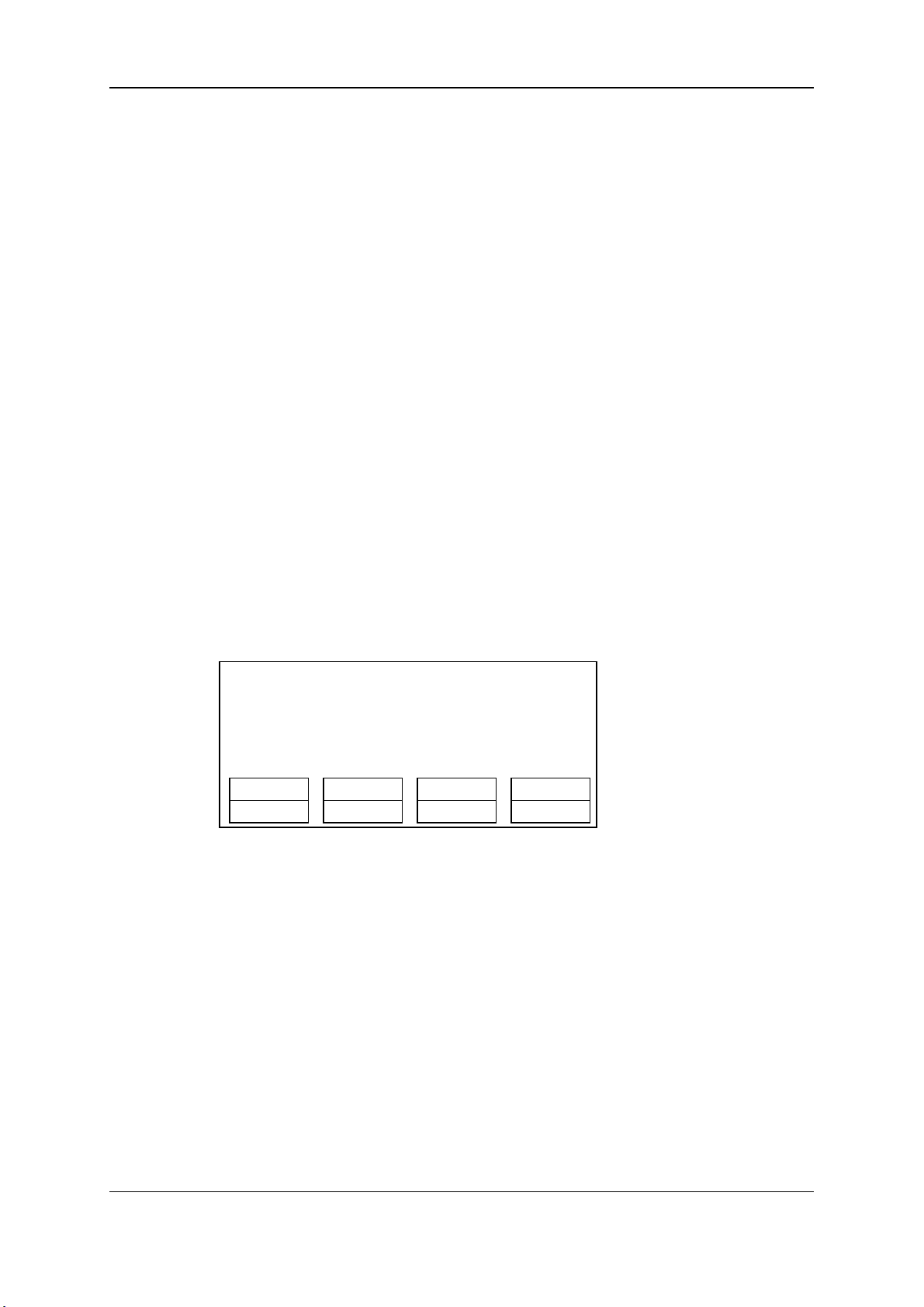
EVS Broadcast Equipment S.A. Issue 11.02.A July2013
OtherAng
The OtherAng (Other Angle)function (SHIFT+C key) allows the operator to replace the
current playlist element by another playlist element showinga different angle of the
recorded material.
When the OtherAng option is selected, Multicam loads the local and network trains that
includethe TC IN of the playlist element to replace. The trains are loaded on the PRV
channel, at the current TC of the loaded element. Thejog is used to shift from one record
train to the other.
Once the requested record train is displayed on the PRV channel, pressing ENTER
replaces the current playlist element by the one created from the selected angle.
Add cut
The Add cut function (SHIFT+D key) allows the operator to split an existing clip into two
independent clips at a selected point. Both resulting clips are duplicates of the original one
with additional short-in and short-out points addedat the split point.
5.3.3. Functions in Playlist Playout Mode
Once the playlist is cued and ready to roll, the menubelow is displayed on the Remote
LCD. This menu gives the operatorthe ability to manipulate the playlist while it is playing.
The duration displayed in the top right corner of the LCD screen in Playlist Playout mode
is the remaining durationuntil the end of the playlist.
PL11 LSM 04 Albert LOC LEFT=00:00:02:22
111A Clipname01200:00:29UnkW00:10
112B/03Clipname45600:53:29 UnkM00:10
112B Clipname89100:53:29 UnkM00:10
2nd CTRL
Film FX Next Skip Edit
Film FX
Selecting this function will create a film style effect during the playout of the playlist by
repeating one field every two fields. Please note that the audio is also affected by this
effect, making it unusable and therefore, muted. This mode is deactivated when exiting a
playlist.
Next
While the playlist is rolling on air, selecting the Next function will start the transition of the
next clip with the transition effect listed onthe playlist. This can be used if a clip is running
too long and it is necessary to shorten up the playing time.
74 5. PlaylistManagement
Page 85

OPERATION MANUAL Multicam LSM 11.02
Skip
While the playlist is rolling, the next clip in the sequence is always displayed on the PRV
screen. The Skip function allows the operator to discard clips before they go on-air. The
clip that will be «skipped» is the one displayedon the PRV screen. This function does not
remove the clip from the playlist, but it simply allows it to be skipped during playback.
Edit
Selecting the Edit function gets the user back to the Playlist Edit mode.
5.4. Playlist Functions on the VGA
5.4.1. VGA Playlist Screen
Introduction
Pressing F10 on the keyboard calls the VGA Playlist screen. The Playlist screen displays
information on the clips included in the current or loaded playlist. Several transport
functions are available from this screen. "Clip Functions on the VGA" on page41 for more
information.
5. PlaylistManagement 75
Page 86

EVS Broadcast Equipment S.A. Issue 11.02.A July2013
Display Depending on the Load Playlist Setting
When the Load Playlist parameter is set to ‘Conditional’ in the Operational Setup menu on
the Remote Panel (P3.3 F2), the information displayed on the VGA Playlist Screen will
differ depending on whether a playlist is loaded on the PGM1or not:
If a playlist is loaded on the PGM1:
• All the informationdisplayed on the Playlist Screen refers to the loaded playlist.
• The PLAY, SKIP, NEXT and RECUE commands are displayed on the blue-
highlighted section at the bottom of the page.
If no playlist is loaded on the PGM1:
• The informationdisplayed on the Playlist screen refers to the current playlist, except
the remaining time, which is not displayed.
• The PLAY, SKIP, NEXT and RECUE commands are NOT displayed on the blue-
highlighted section at the bottom of the page.
5.4.2. VGA Playlist Bank Screen
Pressing END on the keyboard when the Clip screen is displayed allows the users to
access the VGA Playlist Bank screenon the given page. This gives an overview on the
playlists and timelines stored on the bank.
76 5. PlaylistManagement
Page 87
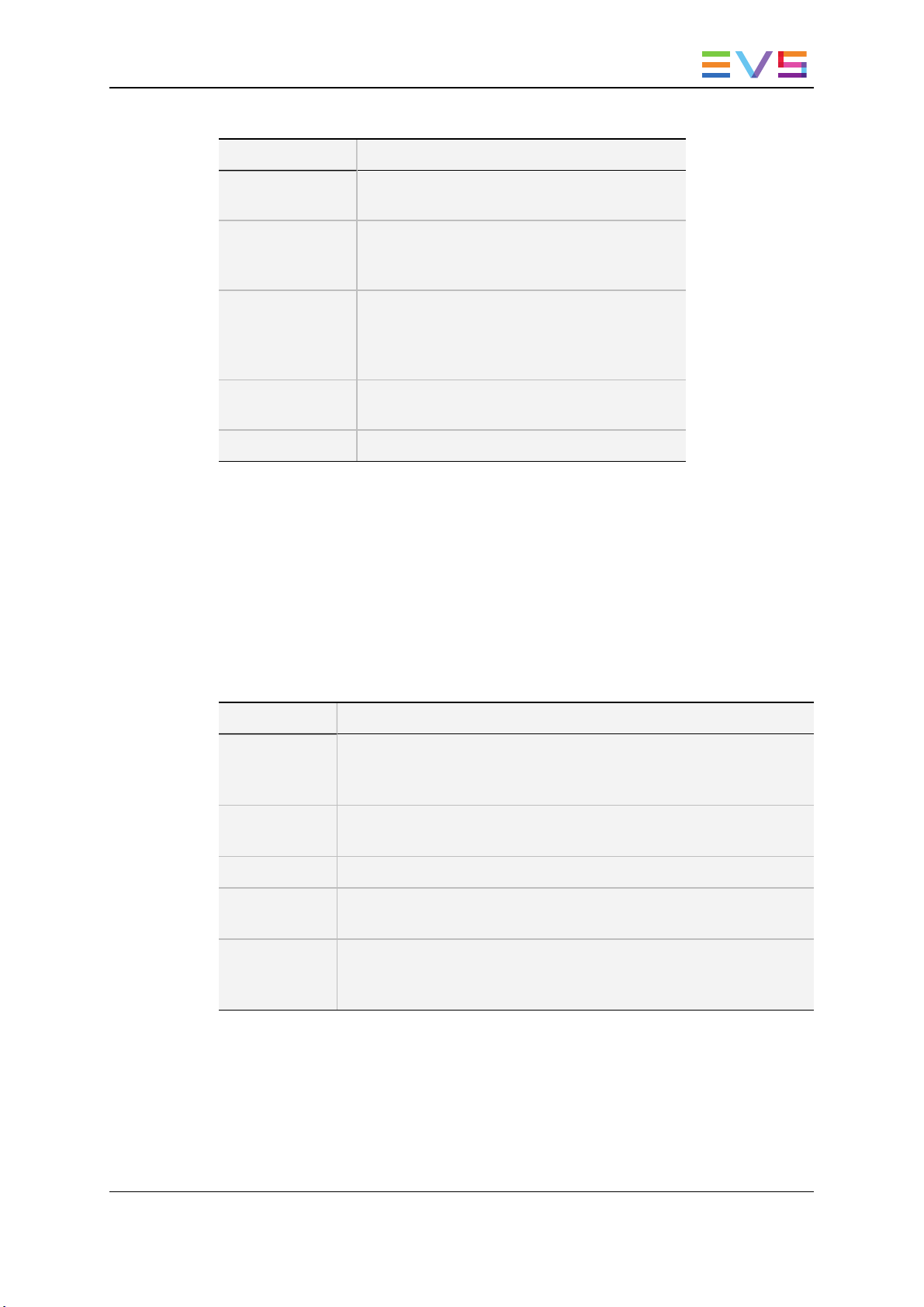
OPERATION MANUAL Multicam LSM 11.02
For each playlist the following information is displayed:
Field Description
Playlist ID Unique identifier of the playlist on the server.
Ex: PL16
Playlist Name Name of the playlist. It cannot exceed 12
characters.
Ex: ”game edit
X clips Number of available clips in the playlist
(unavailable network clips are not taken into
account).
Ex: 98 clips
Dur: --:--:--:-- Total playback duration with available clips.
Ex: 00:04:34:12
Aux Clip Aux Clip ID and name of the audio auxiliary clip.
5.4.3. Editing Functions in VGA Playlist Screen
To use the following commands, you must be in Playlist Edit or Playlist Playout mode:
• To enter the Playlist Edit mode, press the PLST key on the EVS Remote. The screen
of the Remote Panel displays the information about the previous, current and next
three clips of the playlist.
• To enter the Playlist Playout mode, press the PLST key again.
The following operations can be performed from the VGA playlist screen:
Criteria Description
Naming a
playlist or the
current clip
PLAY/pause Press ALT+P to start the playback / pause of the playlist from the
RECUE Press ALT+R to recue to the beginning of the playlist and pause.
NEXT Press ALT+N while the playlist is playing to force immediately the
SKIP Press ALT+S while the playlist is playing to skip the next clip. The
For more information, see section "Naming a Playlist or Playlist
Element" on page 85.
current position.
transition to the next clip in the playlist.
current clip will play until the defined OUT point, thanthe playlist will
skip the next one and play the one after instead.
5. PlaylistManagement 77
Page 88

EVS Broadcast Equipment S.A. Issue 11.02.A July2013
5.5. Operations on Playlists
5.5.1. Setting and Loading Playlists
Introduction
A distinction is made betweensetting and loading a playlist:
• Whenyou load a playlist, you actually load it on a given playerchannel either to edit it
or to play it out.
• Whenyou set the current playlist, you access the playlist location on the serverbut
you do not load it on a player channel. Thus you can insert clips directly in the current
playlist without having to load it onto a channel.
Note
At Multicam startup, the current playlist is automatically playlist 11,that is the
playlist 1 on bank 10 of page 1.
How to Set the Current Playlist
In the Remote Panel Interface
To set the current playlist, proceed as follows:
1. Only if you want to select a distant playlist, first press SHIFT+Network then press the
F_ keycorresponding to the server on which the playlist is located.
2. Press SHIFT+Page+F_ keyto select the page in which the desired playlist is located.
3. Press SHIFT+F10 to select the playlist bank.
4. Press F_ keyto select the desired playlist.
5. Press ENTER to confirm.
78 5. PlaylistManagement
Page 89

OPERATION MANUAL Multicam LSM 11.02
To load the current playlist, continueas follows:
6. Press PLST to load the current playlist on a player channel (it cannot be empty).
To exit the playlist mode:
7. Press the RECORD key to returnto E2E mode.
Notes:
• If the new playlist is not empty, it is automatically loadedon the selected player
channel (in 3 PGM mode) or on the PGM (in PGM/PRV mode) and it becomes the
current playlist.
• If the new playlist is empty, the system will ask you whether you want to copy the
current playlist at this new location.
Note
Page 1 contains playlists 10 to 19, Page 2 contains playlists 20 to 29, andso on.
In the VGAInterface
To set the current playlist, proceed as follows:
1. From the clip screen, press END to access the playlist bank.
2. Press DOWNARROW to select the playlist that you want to define as the current
playlist.
3. Press ENTER on the selected playlist to set it as the current playlist.
How to Recall and Load a Playlist
You can only recall and load a playlist if this is not empty.
To load a playlist on a playerchannel, proceed as follows:
1. Access the desired playlist bank by pressing F10 from the requested page.
2. Select the playlist to load with the F1-F10 keys.
The selected playlist becomes current and is displayedon the LCD display.
3. Press PLST key onthe Remote Panel to loadthe current playlist.
If the new playlist is not empty, it is automatically loaded on the selected player channel
(in 3 PGM mode) or on the PGM (in PGM/PRV mode)and it becomes the current playlist.
If the new playlist is empty, the system will ask you whetheryou want to copy the current
playlist at this new location.
5.5.2. Rolling a Playlist
How to Roll a Playlist
After recalling a playlist, you will roll the playlist using the pre-defined speed of each clip.
Use the PLAY key to start rolling the playlist.
5. PlaylistManagement 79
Page 90

EVS Broadcast Equipment S.A. Issue 11.02.A July2013
Playlist Speed
• As soonas the lever is used to start the playback or during playback, the pre-set
speed for the current clip is canceled and set by the lever position only.
• The playlist will return to pre-set speed mode as soon as another clip with a pre-set
speed is found.
• If the speed for a Super Motion clip is set to “UNK”, pressing the PLAY key on that
clip will start the playback of the playlist at 33%.
Note
When using the PLAY key to start the playlist, it is recommended to set the
lever at the top position (100%). If the lever is in low position and the operator
touches it by mistake while the playlist is rolling, the playlist could freeze on-air.
5.5.3. Deleting Playlists
Note
Deleting a playlist deletes all the playlist elements from the playlist as well as
the playlist definition in the database.
In the Remote Panel Interface
To delete a playlist, proceed as follows:
1. Press SHIFT+Page+F_ keyto select the page in which the playlist to delete is
located.
2. Press SHIFT+F10 to select the playlist bank.
3. Press CLEAR+F_ key to delete the corresponding playlist.
4. According to the value of the Confirm del clp/plst parameter in the Operational
Setup menu(p.5.1 F3), you will be asked or not to confirm the deletion action.
5. The empty playlist location remains available.
80 5. PlaylistManagement
Page 91

OPERATION MANUAL Multicam LSM 11.02
To delete all playlists stored on a same bank, proceed as follows:
1. Press SHIFT+Page+F_ keyto select the page in which the playlists to delete are
located.
2. Press CLEAR+SHIFT+F10to delete all playlists stored in the corresponding bank.
The following confirmation message is displayed:
Caution:
This will delete all playlists/
timelines stored on bank 0
[Menu] : Cancel [Enter] : Confirm
3. Press ENTER to confirm the deletion. All playlists andtimelines on the selected bank
will be deleted.
In the VGAInterface
To delete a playlist, proceed as follows:
1. In the Clip window, go to the requested playlist bank by pressing ALT+Down Arrow
in the requested page.
2. Highlight the requested playlist and press CTRL+DEL to delete the playlist entry.
5.5.4. Copying Playlists
Introduction
From the VGA Clip screen, you can copy or move playlists, through cut, copy and paste
commands, in the same way as you do with clips.
From the Remote Panel, you can only copy playlists.
The copy process is seamless to the user as long or short copies of a playlist are
performed as a background process. If the destination playlist is recalled and the on-air
playlist element has not yet been transferredto the local machine, the on-air element
playedout is the original one. The on-air element will be automatically copied locally when
the playlist will be removedfrom the playout channel.
Copy Options
When you copy a distant playlist from the VGA, or a local/distant playlist from the Remote
Panel to the local EVS server, you have different options:
• The EDL copy copies only the playlist definition while the playlist elements remain at
their original location.
5. PlaylistManagement 81
Page 92
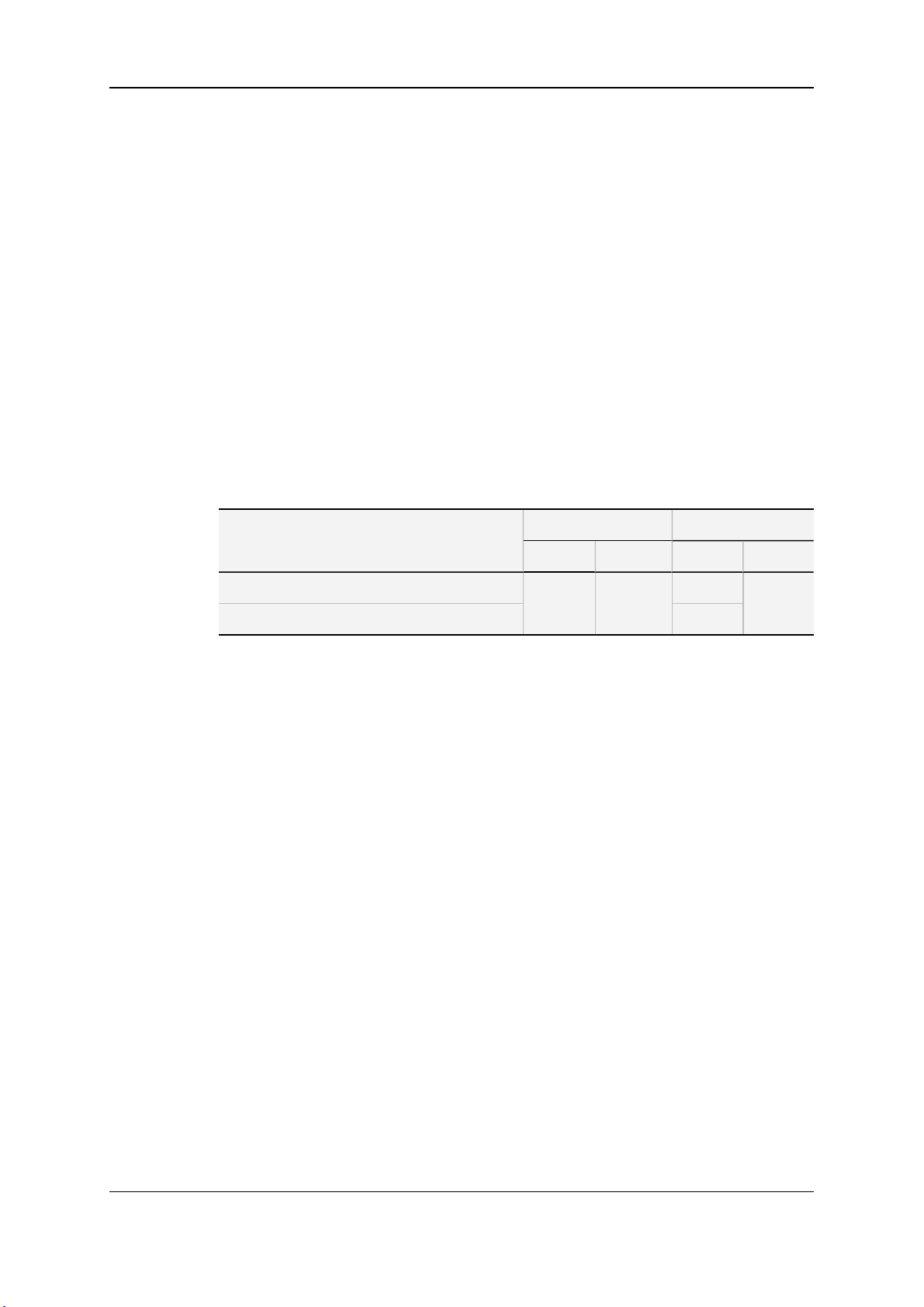
EVS Broadcast Equipment S.A. Issue 11.02.A July2013
• The EDL+Clips copy copies the playlist definition and the playlist elements to the
destination. In this case, you must also choose one of the following:
◦ The short copy that copies only the material included betweenthe IN and OUT
points of the playlist elements with the clip guardbands as defined on the
destination system.
◦ The long copythat copies the complete original clips. This makes a difference
when the playlist elements have been trimmed compared to the original clip.
EDL+Clips copy processes cannot be queued. If the operator tries startinga new copy
process while the previous one is still running, a message will ask him whether he wants
to stop the previous process to start the new one, orcancel his new request.
Available Copy Actions
The basic principle is that only copies to the local EVS serverare possible, whereas
copies to a distant EVS serverare not supported.
The following table provides an overview on the copy actions available from the Remote
Panel and from the VGA interface. The playlists are copied to an empty playlist position:
L = local playlist/position
D = distant playlist
EDL Copy
EDL+Clips Copy (short or long) No
• To play back a selected clip, with the lever, at a speed varying from 0% to a given
maximum speed, you needto do the following:
◦ Define the requested maximum speed in the PGM Speed/Var max parameter
(p.9.1 F3) in the Operational Setup menu.
◦ Select (highlight) the VarMax option in the secondary menu in PGM/PRV mode.
Remote Panel VGA Interface
L to L D to L L to L D to L
Yes
Yes Yes
Yes
In the Remote Panel Interface
To copy a playlist, proceed as follows:
1. Go to the source playlist bank (local or from another machine on the network).
2. Select the original playlist to copy by pressing the corresponding F_ key.
3. Go to the destination playlist bank.
82 5. PlaylistManagement
Page 93

OPERATION MANUAL Multicam LSM 11.02
4. Select an empty playlist location.
A new menu appears on the LCD display of the Remote Panel, with the corresponding
message on the OSD of the output monitors, asking whetheryou want to copy the
original playlist to the new location or whether you simply want to select a new, empty
playlist (default choice):
Select New Playlist 13 ?
[Menu]: Cancel
[Enter]: Confirm
COPY NEWPLST
5. Press COPY (A key) to select the copy option. The menu becomes:
Copy Playlist 11/03
to Playlist 13 ?
[Menu]: Cancel
[Enter]: Confirm
COPY PLST+CLP NEWPLST
6. Specify whetherto copy the EDL with or without the clips:
◦ Press ENTER to copy only the EDL without copying the elements contained in
the original playlist. The copy is done instantly since there is no material to
transfer.
◦ Press PLST+CLP (B key) to copy the EDL together with the playlist elements.
The display becomes:
Copy Playlist and all net. clips
to Playlist 13 ?
[Menu]: Cancel
[Enter]: Confirm
COPY PLST+CLP SHORT NEWPLST
5. PlaylistManagement 83
Page 94

EVS Broadcast Equipment S.A. Issue 11.02.A July2013
7. Press the C key to specify whether to perform a SHORT ora LONG copy.
◦ SHORT mode (default): only the section of the elements between the Short IN
andShort OUT as defined in the playlist will be copied, increased by the duration
of the guardbands, as defined on the destination system.
◦ LONG mode: the entireoriginal clips, including their guardbands, will be copied on
the destination system.
8. Press ENTER to confirm the copy or MENU to cancel.
The F_ keyof the destination playlist will flash until all clips have been copied. This
playlist can be recalledduringthat process for browsing, editing, orplayback. If some
clips have not yet been copied, the original network clip is used instead.
In the VGAInterface
How to Copy a Local Playlist
To copy a localplaylist, proceed as follows:
1. Press the END key to open the playlist bank.
2. Select the playlist to copy.
3. Press CTRL+C to copy the playlist or CTRL+X to move it.
4. Go to the empty playlist location on the same server where you want to copy the
playlist.
5. Press CTRL+V to paste the playlist. The EDL of the playlist is copied to the
requested location.
How to Copy a Distant Playlist
To copy a distant playlist, proceed as follows:
1. Press F9 to open the Connect window.
2. With the DOWN ARROW and UPARROW keys, select the distant serverfrom
which you want to copy a playlist.
3. Press ENTER.
4. Press END to go to the playlist bank on the requested page.
5. Select the original playlist to copy with the DOWN ARROW and UPARROW keys.
6. Press CTRL+C to copy the playlist or CTRL+X to move it.
7. Press F9 to open the Connect window.
8. Select the local serverand press ENTER.
9. On the requested playlist bank, select an empty playlist location on your local
machine.
84 5. PlaylistManagement
Page 95

OPERATION MANUAL Multicam LSM 11.02
10. Press CTRL+V to paste the playlist.
The following dialog box pops up:
Copy Playlist xx/xx to yy.
Select Copy Playlist Mode (Space Bar)
Playlist Only
Playlist with Clips: Short Mode
Playlist with Clips: Long Mode
Esc: Cancel - Enter: Confirm
11. Press the SPACEBAR to select the requested copy option.
12. Press ENTER to confirm. The playlist is copied to the requested location.
Merging Playlists
From the VGA Interface, it is possible to merge two playlists by copyinga playlist and
pasting it to an existing playlist. The copied playlist will be added at the end of the
destination playlist.
5.5.5. Naming a Playlist or Playlist Element
Introduction
You can name or rename a playlist or one of its elements only from the VGA interface.
Note
When entering a name, use BACKSPACE to delete the last character or ESC
to clear the entire field.
How to Name a Playlist
From the Playlist Bank Window
To name a playlist from the VGA Playlist Bank window, proceed as follows:
1. From the Clip screen, press END to go to the Playlist Bank screenof the requested
page.
2. Use the DOWNARROW to select the playlist to name.
3. Enter the desired nameon the keyboard. It appears in the Name field at the bottom of
the screen.
4. Press F1 to assign the new name to the selected playlist. The playlist name appears
in the title bar next to the playlist number.
5. PlaylistManagement 85
Page 96

EVS Broadcast Equipment S.A. Issue 11.02.A July2013
From the Playlist Window
To name the current playlist from the VGA Playlist window, proceedas follows:
1. Press F10to open the VGA Playlist screen. The current playlist is displayed.
2. Enter the desired nameon the keyboard. It appears in the Name field at the bottom of
the screen.
3. Press SHIFT+F1 to assign the new name to the current playlist. The playlist name
appears in the title bar next to the playlist number.
How to Name a Playlist Element
To name the current element in the loaded playlist from the VGA Playlist window, proceed
as follows:
Note
This function is only available when the playlist is the current one in Playlist Edit
mode (PLST EDIT) orPlaylist Playout mode (PLST DIFF) on the Remote
Panel.
1. Press F10to open the VGA Playlist screen. The loadedplaylist is displayed and the
current playlist element on the Remote Panel is selected.
2. Enter the desired namefor the element on the keyboard. It appears in the Name field
at the bottom of the screen.
3. Press F1 to assign the new name to the current element. The name for the current
element appears in the Name columnof the selected element.
Note
Naming the current element of the loaded playlist will affect the original clips.
5.5.6. Consolidating a Playlist
Introduction
Using the internal loop, you can recorda playlist back to the server as a big clip if you
want, for example, to record the playlist effects (split screen, target tracking, painting,
etc.) as regular video inside the server.
You can only consolidate a playlist from the Remote Panel.
Depending on the Internal Loop parameter in the Operational Setup menu (p.9.2 F6),
both video and audio can be loopedback into the system, or only the videotrack is looped
andthe system keeps recording the live audio at the same time.
86 5. PlaylistManagement
Page 97

OPERATION MANUAL Multicam LSM 11.02
How to Loop Back a Playlist into the Server
To consolidate a playlist using the internal Loop mode, proceed as follows:
1. Add the requested effects to the playlist.
2. Recue the playlist.
3. Activate the Loop mode via the SHIFT+Loop key.
4. Roll the playlist.
The playlist will be recorded onto the disks (Channel 1 – CAM A) as a continuous
video/audio stream.
When you exit the playlist mode, go back to LIVE record andsimply jogback, you will see
the playlist recordedwith all its transitions and at the speed they were played.
5.5.7. Generating a Continuous TC in a Playlist
Introduction
From the VGA interface, you can regenerate a continuous timecodefor the wholeplaylist
or for each clip of a playlist. This can be useful when:
• You donot want to have a playlist with disrupted timecodes from the various playlist
elements.
• You want to change the timecode type in the VITC or LTC timecode.
Settings for Continuous Timecode in Playlists
The following table describes the various parameters that should be defined when
regenerating the timecode in a playlist:
Parameter Description
Continuous in … Specifies whether the TC should be continuous
for the whole playlist or for each playlist element.
From … Specifies the initial TC valueto be used for the
timecode regeneration
Possible
Values
PLST, CLIP
Timecode,
LTC TC, User
TC
In … Specifies the TC type in which the timecode
should be regenerated
5. PlaylistManagement 87
LTC or VITC
in SD
HANC VITC,
HANC LTC,
or both
Page 98

EVS Broadcast Equipment S.A. Issue 11.02.A July2013
How to Activate the Continuous Timecode Regeneration
To activate the continuous timecode regeneration, proceed as follows:
1. In the Playlist page (F10), press TAB several times until the ON/OFF field after
‘Regeneration of TC’ is green highlighted.
2. Press the right arrow key to toggle the function to ON.
3. Press TAB again to highlight the 'continuous in PLST' text segment, and, with the
right arrow, select whether the regeneration will be applied on the playlist (PLST) or on
the playlist clips (CLIPS).
4. Press TAB to highlight the 'from 00:00:00:00' segment, and type the start TC to be
used for the regeneration.
5. Press TAB again to highlight on the timecode type, and toggle to the requested
timecode type with the right arrow.
The continuous timecode regenerationfunction is now active. However, the timecodewill
effectively be regeneratedwhen you replay the playlist after activating a loop.
To deactivate the function, press the left arrow on the field to toggle the function to ‘OFF’.
How to Regenerate the Timecode in a Playlist
To regenerate the timecode in a given playlist, proceed as follows:
1. Activate the TC Regeneration and define the related settings on the Playlist page
(F10), in the blue-highlighted area at the bottom of the page. This feature is definedfor
each playlist individually:
2. Activate the internal loop using the SHIFT+Loop keys
3. Roll the playlist.
This will record the playlist back into the recorder channel 1 (CAM A) with the regenerated
timecode.
5.6. Operations on Clips in Playlists
5.6.1. Adding Clips in a Playlist
Introduction
You can add clips to a playlist in different ways, but always from the Remote Panel:
• Adding clips at the endof the current playlist without entering the Playlist Edit mode.
• Inserting clips before or after the clip selected in the loaded playlist.
• Adding one or more clips returned by a search at the endof the current playlist.
88 5. PlaylistManagement
Page 99

OPERATION MANUAL Multicam LSM 11.02
How to Add Clips at the End of the Current Playlist
You can create a playlist very quickly. The experienced operator can include a clip at the
endof the playlist containing an action that happened seconds before the playlist is played
on air. To add clips quickly at the end of the current playlist, you do not have to enter the
Edit mode.
To add clips to the current playlist, proceedas follows:
1. Activate a playlist as the current playlist.
2. Recall the first clip for your playlist.
3. Press ENTER on the Remote Panel.
The clip is added at the end of the current playlist.
4. Repeat as many times as necessary until the last clip is entered.
How to Insert Clips into a Playlist
The following rules apply to the procedure below:
• You need to be in PGM/PRV mode to beable to use the TAKE key on the Remote
Panel to insert a clip.
• Depending on what is selected for the Insert in playlist parameter in the Operational
Setup menu(p.3.1 F6), the clip will be inserted beforeor after this selected position.
To insert a clip into a playlist, proceedas follows:
1. Using the Playlist Edit mode or the Browse mode, scroll to the location where the clip
must be inserted.
2. Call the selected clip. It appears on the PRV output.
3. Do one of the following to insert the selected clip in the playlist, at the position shown
on the PGM output:
◦ Press the A key (Insert function) on the Remote Panel
◦ Press the TAKE key on the Remote Panel
◦ Press the SHIFT+INSERT keys on the Remote Panel
A confirmation message will appearif that option has been enabled in the Setup menu.
After the clip has been inserted, you can press PLST to returnto the playlist at the current
position.
5. PlaylistManagement 89
Page 100

EVS Broadcast Equipment S.A. Issue 11.02.A July2013
How to Insert the Result of a Clip Search into a Playlist
Working Principles
• In Playlist Edit mode with a PRV channel, whenPRV CTL is enabled, the operator
has full control of the PRV channel while the playlist remains loaded on the PGM
channel.
• On the PRV channel, you can perform all clip-related functions, including database
search usingtimecode, keywords and ranking, from the VGA Search Screen as well
as from the secondary clip menu of the Remote Panel.
• Once the desired clips are found, they can easily be inserted in the playlist that is still
loaded on the PGM output. By switching PRV CTRL ON or OFF, you can very easily
combine playlist editing and database search functions.
Procedure
To insert one or more clips from a search result at the endof the current playlist, proceed
as follows:
1. From the main menu, activate the current playlist.
PGM1 CAM A *PRV1* CAM B
Aud.Met. PgmSpd Sort->TC PostRoll
Mix. Sw to IN Search Pref
P.1 B.1 Clips: LOCAL Records: LOCAL
PL 11:
Msg:
Rst Cam Local Sync Prv 2nd CTRL
Cam A Cam B Cam C Cam D
2. Press MENU+C to enter the Search mode:
1 keyword890 2 keyword890 3 keyword890
F1:action_1 F6:action_6
F2:action_2 F7:action_7
F3:action_3 F8:action_8
F4:action_4 F9:Prev.pagep.01
F5:action_5 F0:Next page
Reset Archive FromDate ToDate
Return *** Srch Loc Srch Net
3. Enter the search criteria.
4. Launch the search on the local serveror on the whole network by pressing
respectively the C (Srch Loc) or D (Srch Net) keys on the Remote Panel.
90 5. PlaylistManagement
 Loading...