

Page 1
USER MANUAL
XEDIO MANAGER
Version 4.2 - June 2012
Page 2

Page 3

Xedio Suite Version 4.2 - User Manual – Xedio Manager
EVS Broadcast Equipment – June 2012
Issue 4.2.B
I
COPYRIGHT
EVS Broadcast Equipment – Copyri ght © 2010-2012. All rights reserved.
DISCLAIMER
The information in this manual is furnished for informational use only and subject
to change without notice. While every effort has been made to ensure that the
information contained in this user manual is accurate, up-to-date and reliable,
EVS Broadcast Equipment cannot be held responsible for inaccuracies or errors
that may appear in th is publication.
IMPROVEMENT REQUESTS
Your comments will help us improve the quality of the user documentation. Do not
hesitate to send improvement requests, or report any error or inaccuracy on this
user manual by e-mail to
doc@evs.tv.
REGIONAL CONTACTS
You will find the full list of addres ses and phone numbers of local offices either at
the end of this user manual (for manuals on hardware products) or on the EVS
website on the followi ng page:
http://www.evs.tv/contacts.
USER MANUALS ON EVS WEBSITE
The latest version of the user manual, if any, and other user manuals on EVS
products can be found on the EVS download center, on the following webpage:
http://www.evs.tv/downloadcenter.
Page 4

Issue 4.2.B
Xedio Suite Version 4.2 - User Manual – Xedio Manager
II
EVS Broadcast Equipment – June 2012
Page 5

Xedio Suite Version 4.2 - User Manual – Xedio Manager
EVS Broadcast Equipment – June 2012
Issue 4.2.B
III
Table of Contents
TABLE OF CONTENTS ................................................................................................. III
WHAT’S NEW? ............................................................................................................. VII
1. INTRODUCTION ..................................................................................................... 1
2. USER INTERFACE ................................................................................................. 2
2.1 OPENING XEDIO MANAGER ..................................................................................................... 2
2.2 OVERVIEW OF THE XEDIO MANAGER WINDOW .................................................................... 2
2.3 MENU BAR .................................................................................................................................. 4
2.4 THE OUTLOOK BAR ................................................................................................................... 6
3. ENCODERS ............................................................................................................ 8
3.1 INTRODUCTION .......................................................................................................................... 8
3.2 PHYSICAL MANAGER ................................................................................................................ 9
3.2.1 Introduction ............................................................................................................................. 9
3.2.2 Creating Physical Enco der .................................................................................................... 10
3.2.3 Setting up the Encoding Parameters ..................................................................................... 11
3.2.4 Modifying the Physical Encoder Properties ........................................................................... 13
3.2.5 Possible Actions with Contextual Menus ............................................................................... 13
3.3 LOGICAL MANAGER................................................................................................................. 14
3.3.1 Introduction ........................................................................................................................... 14
3.3.2 Creating Logical Encoder ...................................................................................................... 14
3.3.3 Modifying the Logical Encoder Properties ............................................................................. 15
3.3.4 Possible Actions with Contextual Menus ............................................................................... 15
3.4 GROUP MANAGER ................................................................................................................... 17
3.4.1 Introduction ........................................................................................................................... 17
3.4.2 Creating a Group of Logical Channels .................................................................................. 17
3.4.3 Deleting a Group of Encode rs ............................................................................................... 18
3.5 SCHEDULER ............................................................................................................................. 18
3.6 PREVIEW ................................................................................................................................... 19
4. LINX AND DIRECT ACCESS ............................................................................... 20
4.1 INTRODUCTION ........................................................................................................................ 20
4.2 GENERAL CONFIGURATION PARAMETERS ......................................................................... 20
4.3 EVS VIDEO SERVER ................................................................................................................ 21
4.3.1 Introduction ........................................................................................................................... 21
4.3.2 EVS Server Parameters ........................................................................................................ 22
4.3.3 How to Gang Recorder Channels ......................................................................................... 23
4.3.4 Possible Actions with Contextual Menus ............................................................................... 23
4.4 EVS VIDEO SERVER GROUP .................................................................................................. 24
5. MACHINES ........................................................................................................... 26
5.1 INTRODUCTION ........................................................................................................................ 26
5.2 VTR MANAGER ......................................................................................................................... 27
5.3 SWITCHER MANAGER ............................................................................................................. 28
Page 6

Issue 4.2.B
Xedio Suite Version 4.2 - User Manual – Xedio Manager
IV
EVS Broadcast Equipment – June 2012
5.4 ARCHIVE SERVER MANAGER ................................................................................................ 30
5.5 XFILE MANAGER ...................................................................................................................... 31
5.6 IPDIRECTOR ............................................................................................................................. 32
5.7 MODIFYING OR DELETING AN EXTERNAL DEVICE .............................................................. 34
6. MEDIA .................................................................................................................. 35
6.1 INTRODUCTION ........................................................................................................................ 35
6.2 MEDIA SERVERS ...................................................................................................................... 36
6.2.1 Introduction ........................................................................................................................... 36
6.2.2 Adding a Media Server .......................................................................................................... 36
6.2.3 Contextual Menus ................................................................................................................. 37
6.2.4 Setting the CDM Encoder Mapped Drive .............................................................................. 39
6.3 CLASS MANAGER .................................................................................................................... 39
6.3.1 Introduction ........................................................................................................................... 39
6.3.2 Possible Actions with Contextual Menus ............................................................................... 40
6.4 MEDIA IMPORTER .................................................................................................................... 40
6.5 RTD MANAGER ......................................................................................................................... 42
6.5.1 Introduction ........................................................................................................................... 42
6.5.2 Possible Actions with Contextual Menus ............................................................................... 42
6.6 MEDIA MANAGER ..................................................................................................................... 43
6.6.1 Introduction ........................................................................................................................... 43
6.6.2 Elements Grid ....................................................................................................................... 44
6.6.3 Searching the Database ........................................................................................................ 47
6.6.4 Delete & Purge ...................................................................................................................... 57
7. METADATA .......................................................................................................... 58
7.1 INTRODUCTION ........................................................................................................................ 58
7.2 PROFILE MANAGEMENT ......................................................................................................... 59
7.2.1 Managing User Fields ........................................................................................................... 60
7.2.2 Managing Metadata Profi l es ................................................................................................. 61
7.3 MEDIA PROFILE ASSOCIATION .............................................................................................. 63
7.4 EDIT PROFILE ASSOCIATION ................................................................................................. 64
8. PLAYOUTS ........................................................................................................... 66
8.1 INTRODUCTION ........................................................................................................................ 66
8.2 SERVERS MANAGER ............................................................................................................... 67
8.2.1 Introduction ........................................................................................................................... 67
8.2.2 Creating and Configuri ng a Pl ayout Server ........................................................................... 67
8.2.3 Modifying the Playout Server Properties ............................................................................... 68
8.2.4 Possible Actions with Contextual Menus ............................................................................... 68
8.3 GROUP MANAGER ................................................................................................................... 68
8.3.1 Introduction ........................................................................................................................... 68
8.3.2 Creating a Group of Playout Servers .................................................................................... 69
8.3.3 Deleting a Group of Playout Servers ..................................................................................... 69
9. SOFTWARES ....................................................................................................... 70
9.1 INTRODUCTION ........................................................................................................................ 70
9.2 PARAMETER PROFILES .......................................................................................................... 71
9.2.1 Introduction ........................................................................................................................... 71
9.2.2 Possible Actions with Contextual Menu ................................................................................ 72
Page 7

Xedio Suite Version 4.2 - User Manual – Xedio Manager
EVS Broadcast Equipment – June 2012
Issue 4.2.B
V
9.2.3 List of <GENERAL> Parameters ........................................................................................... 73
9.2.4 List of Parameters for Xedio Manager ................................................................................... 80
9.2.5 List of Parameters for Xedio CleanEdit ................................................................................. 81
9.2.6 List of Parameters for Xedio Ingest ....................................................................................... 95
9.2.7 List of Parameters for Xedio Playout Organizer .................................................................... 95
9.2.8 List of Parameters for Xedio Browse and Xedio Browse (VC) ............................................... 96
9.2.9 List of Parameters for Xedio Approval ................................................................................... 97
9.2.10 List of Parameters for Xedio Importer ................................................................................... 98
9.2.11 List of Parameters for Xedio Explorer ................................................................................... 98
9.2.12 List of Parameters for Xedio Cutter ....................................................................................... 99
9.2.13 How to Edit a Parameter Profile .......................................................................................... 102
9.3 KEYBOARD PROFILES ........................................................................................................... 103
9.3.1 Introduction ......................................................................................................................... 103
9.3.2 Possible Actions with Contextual Menu .............................................................................. 103
9.3.3 How to Edit a Keyboard Shortcut ........................................................................................ 103
9.3.4 List of Xedio CleanEdit Key boar d Keys Ass i gnments ......................................................... 104
9.3.5 List of Xedio Playout Organi zer Keyb oar d Keys As si gn m ents ............................................ 113
9.3.6 List of Xedio Browse and Xedio Browse (VC) Keyboard Keys Assignments ....................... 114
9.3.7 List of Xedio Cutter Keyboard Keys Assignments ............................................................... 115
9.4 KEYBOARD MACHINES ......................................................................................................... 118
9.4.1 Introduction ......................................................................................................................... 118
9.4.2 Possible Actions with Contextual Menu .............................................................................. 118
9.5 VIDEO FX ................................................................................................................................ 119
9.5.1 Introduction ......................................................................................................................... 119
9.5.2 Editing Default Parameters for Effects ................................................................................ 119
10. TOOLS ................................................................................................................ 120
10.1 INTRODUCTION ...................................................................................................................... 120
10.2 PROGRAM CLASS MANAGER ............................................................................................... 121
10.2.1 Introduction ......................................................................................................................... 121
10.2.2 Possible Actions with Contextual Menus ............................................................................. 121
10.3 PROJECTS / CLIPS / EDITS / PLAYLISTS MANAGER .......................................................... 122
10.3.1 Introduction ......................................................................................................................... 122
10.3.2 Element Grid ....................................................................................................................... 122
10.3.3 Searching the Database ...................................................................................................... 126
10.3.4 Delete & Purge .................................................................................................................... 126
10.4 BROADCASTED ITEMS MANAGER ....................................................................................... 126
10.5 SCRIPT MANAGER ................................................................................................................. 127
10.6 MONITORING .......................................................................................................................... 128
11. USERS ................................................................................................................ 129
11.1 INTRODUCTION ...................................................................................................................... 129
11.2 USER MANAGER .................................................................................................................... 130
11.2.1 Introduction ......................................................................................................................... 130
11.2.2 Creating a User ................................................................................................................... 131
11.2.3 Possible Actions with Contextual Menu .............................................................................. 131
11.3 ORIGIN MANAGER ................................................................................................................. 132
11.3.1 Introduction ......................................................................................................................... 132
11.3.2 Contextual Menus ............................................................................................................... 132
11.4 LICENSE MANAGER ............................................................................................................... 133
Page 8

Issue 4.2.B
Xedio Suite Version 4.2 - User Manual – Xedio Manager
VI
EVS Broadcast Equipment – June 2012
12. MEDIA FILE CLEANER ...................................................................................... 134
Page 9

Xedio Suite Version 4.2 - User Manual – Xedio Manager
EVS Broadcast Equipment – June 2012
Issue 4.2.B
VII
A GUID parameter can be used at metadata profile
creation to link the profile to the same one from
ted with its
What’s New?
The following table descr ibes the sections updated to reflect the new a nd modified
features on Xedio Mana ger from Xedio Suite 4.02 (compar ed to Xedio Suite 4.01).
In the user manual, the icon has been added on left margin to highlight
information on new and updated features.
Click the section number (or the description) in the table to jump directly to the
corresponding section.
Section Description
7.2.2
IPDirector. So, if the media/edit is expor
custom metadata to IPDirector, the metadata profile will
be recognized by IPDir ector.
9.2 Updated list of Parameter Profi les.
9.3 Updated list of Keyboard Profil es.
Page 10

Page 11

Xedio Suite Version 4.2 - User Manual – Xedio Manager
EVS Broadcast Equipment – June 2012
Issue 4.2.B
1
1. Introduction
An installation of Xedio Suite can include a single workstation providing a single
fast and easy editing facility or a range of workstations running the various
applications included in the sui te to provide a complete newsroom or sports centre
video production solution.
Each installation of a Xedio Suite requires its own specific config uration and set of
parameters. All the workstations, the users, their associated projects, and the
whole media pool are available to the system. Each of these is referenced within
the Xedio database.
Xedio Manager is the application within the suite that manages the configuration
of the installation and defines the parameters us ed by the system.
Xedio Manager is designed for system administrators to easily use and set the
system up from the very beginning of the installation to the daily asset and
content management.
Xedio Manager can be installed on all computers connected to the Xedio network.
The only requirement is an ODBC connection to the database; o therwise there are
no specific computer o r network requirements nec essary to enable use.
Page 12
Issue 4.2.B
Xedio Suite Version 4.2 - User Manual – Xedio Manager
2
EVS Broadcast Equipment – June 2012
2. User Interface
2.1 OPENING XEDIO MANAGER
To start the Xedio Manager application, click on the Xedio Manager
icon on the desktop.
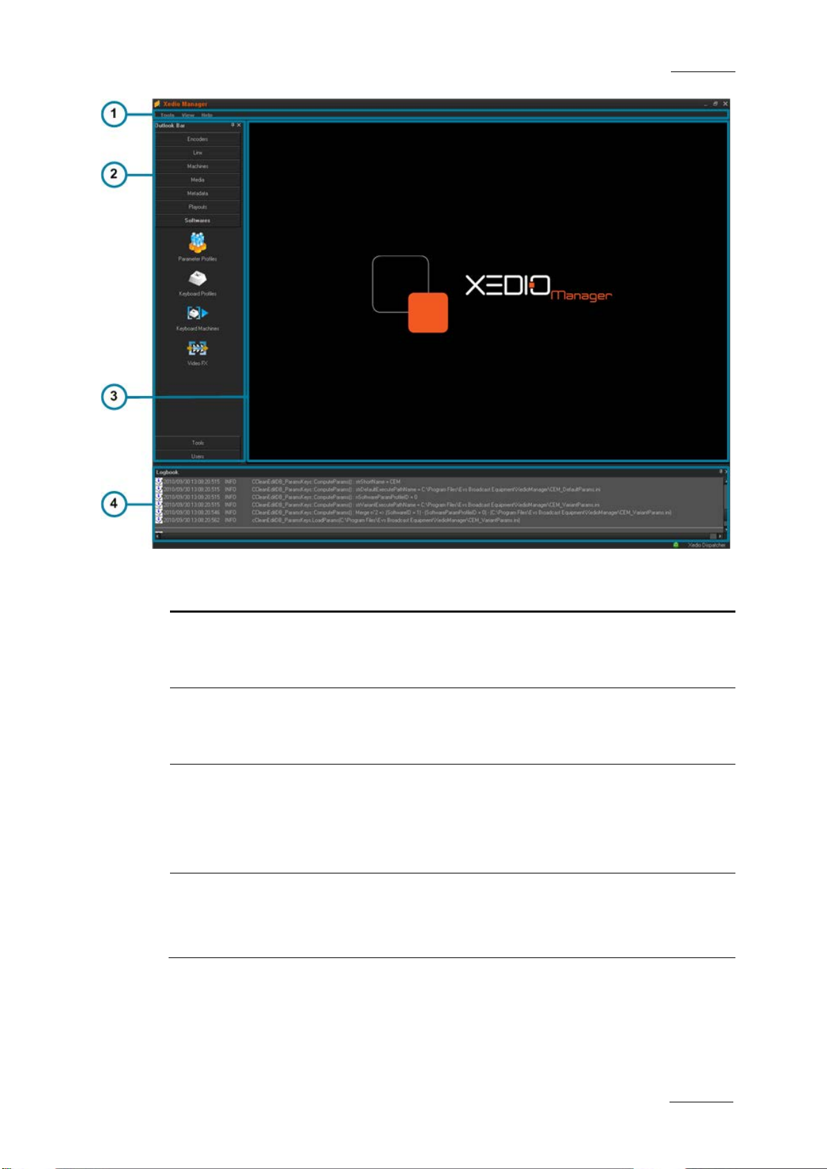
2.2 OVERVIEW OF THE X EDIO MANAGER WINDOW
The Xedio Manager user interface consists of several areas highlighted on the
following screenshot and shortl y described in the table below.
Note
The color of some user interface elements may vary with the Xedio skin
installed.
Page 13
Xedio Suite Version 4.2 - User Manual – Xedio Manager
EVS Broadcast Equipment – June 2012
Issue 4.2.B
3
The menu bar gives access to general commands and to
to the
Area Description
1. Menu bar
configuration paramete rs.
See the section 2.3 ‘Men u bar’ on page 4.
2. Outlook bar The Outlook bar presents nine tabs corresponding
areas managed by Xedio Manager.
See section 2.4 ‘The Outlook Bar’ on page 6.
3. Work area The Work area is only a ctive when an item is sele cted in one
category from the Outlook area. Thus, the window displayed
in the Work area depends on the selected item. Parameters
are set from this area .
See sections 3 to 11.
4. Logbook
area
The Logbook area lists the operations that the user perf orms
in the database and their status. If a problem occurs, an
error message is added in the list. At the same time, the
application saves all this information in a l og file.
Page 14
Issue 4.2.B
Xedio Suite Version 4.2 - User Manual – Xedio Manager
4
2.3 MENU BAR
TOOLS MENU
The Tools menu gives access to the Media File Cleaner tool. This tool shows the
list of all the media files presen t on the Xedio media servers but not referenced in
the database (orphan files). From the Media File Cleaner window, it is possible to
delete these orphan f iles. Refer to section 12 ‘Media File Cleane r’ on page 134 for
more information.
VIEW MENU
The View menu provides the following options:
Menu Item Description
Outlook Bar Displays or hides the Outlook bar.
EVS Broadcast Equipment – June 2012
Logbook Bar Displays or hides the Logbook bar.
Full Screen Hides the Menu bar.
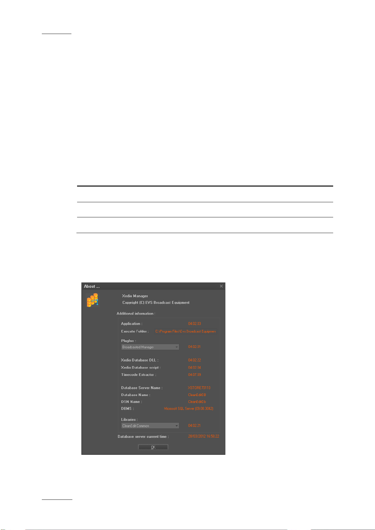
HELP MENU
The Help menu provides the About… option which gives information about the
system, such as version number of the different components.
The window gives the f ollowing information:
Page 15

Xedio Suite Version 4.2 - User Manual – Xedio Manager
EVS Broadcast Equipment – June 2012
Issue 4.2.B
5
version is
Version number of the DLL allowing the access to the
It must be compatible with the CleanEdit Database DLL
Information Item Meaning
Application Version number of Xedi o Manager.
Execute Folder Folder Path where Xedio Manager is installed.
PlugIns List of the installed plug-in. When the user selects a plug
in name from the list, the corresponding
displayed next to the field.
Xedio Database
DLL
Xedio database.
Xedio Database
Version number of the database.
Script
version number.
Timecode Extractor Version number of the application which checks the media
and the timecode insid e the media.
Database Server
Name of the server wher e the database resides.
Name
Database Name Name of the database i n SQL server.
DSN Name Data Source Name, label of the currently used OD BC link.
DBMS Databa se Management System type and version.
Libraries List of the existing DLL libraries. When the user selects a
library name from the list, the corresponding version is
displayed next to the field.
Database Server
Date and time from the Database server.
Current Time
Page 16
Issue 4.2.B
Xedio Suite Version 4.2 - User Manual – Xedio Manager
6
interactions with external devices such as VTR,
Manages the creation of metadata profiles which could be
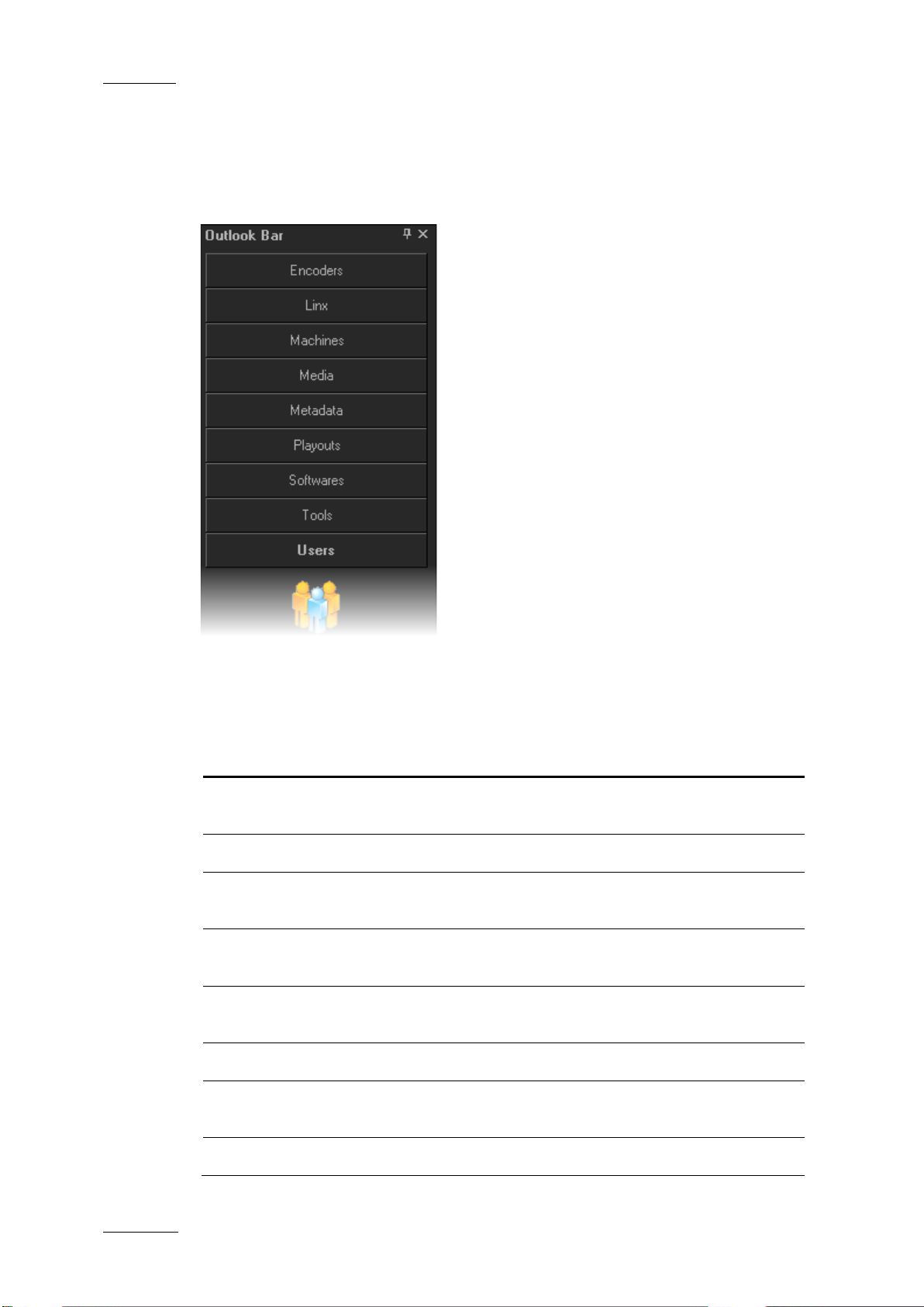
2.4 THE OUTLOOK BAR
The Outlook bar presents nine tabs. They correspond to the areas managed by
Xedio Manager.
EVS Broadcast Equipment – June 2012
When Xedio Manager is started for the first time, only the Media and Users tabs
are shown. You need to create a media server before being able to see all the
tabs. See section 6.2 ‘Media Servers’ on page 36.
The following table briefly describes the va rious categories:
Subject Purpose
Encoders Manages (create, delete and modify) encoders and sets up
their parameters.
LinX Manages interactions wit h EVS video servers.
Machines Manages
archive servers, XFile and EVS servers.
Medias Manages all media and associated storage structure as
referenced in the dat abase.
Metadata
associated to media.
Playouts Manages the playou t servers used by the Xedio Suite.
Softwares Sets up all software parameters and allows the creation of
parameter profiles.
Tools Manages database content and user s jobs.
Page 17

Xedio Suite Version 4.2 - User Manual – Xedio Manager
EVS Broadcast Equipment – June 2012
Issue 4.2.B
7
Subject Purpose
Users Manages users and access rights.
Each category provides access to a series of items. Once a category tab is
selected, its specific items are shown as icons. Select any of these icons to
display its relevant interface in the Work area.
Refer to the different chapters of the present manual for complete information on
each category managed by Xedio Manager.
Page 18
Issue 4.2.B
Xedio Suite Version 4.2 - User Manual – Xedio Manager
8
efines hardware setup and encoding parameters for
the combination of
at make
3.1 INTRODUCTION
Encoders are physical devic es which allow the digitization o f incoming audio/video
feeds into multiple file formats. Most of the models are configured to encode lores or hi-res feed. They can be logically grouped to associate physical encoders
handling the same feed, either in hi-res or in lo-res. So, editing operation s can be
quickly performed on lo-res media and then reflected to the corresponding hi-res
media for further news production and playout.
The XEDIO I/O encoder model is a ble to encode both lo-res and hi-res at the same
time.
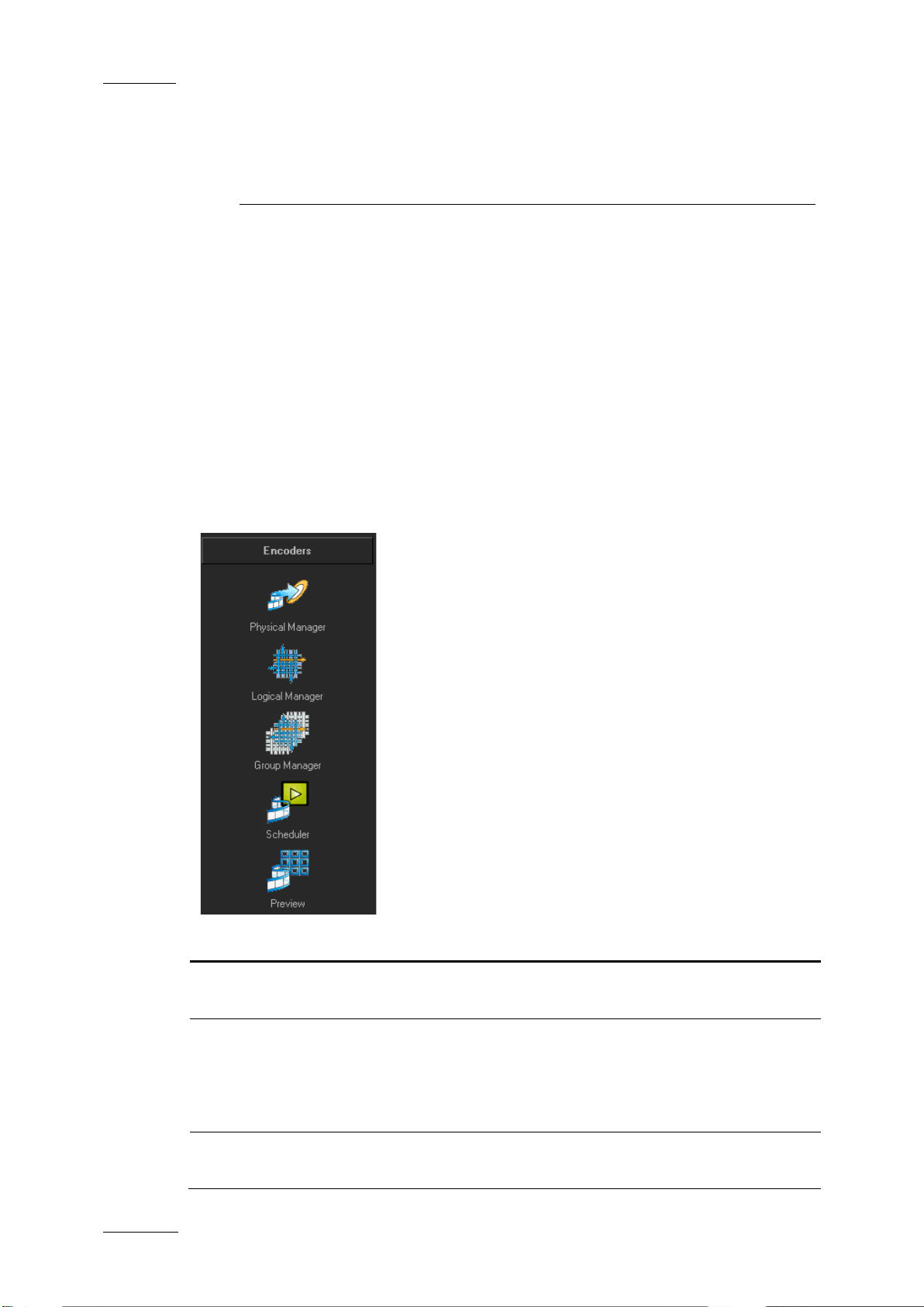
Five items are available in the Encoders category. They are detailed in the table
below.
EVS Broadcast Equipment – June 2012
3. Encoders
Item Description
Physical Manager
Logical Manager Defines the logical encoders, i.e.
Group Manager Allows to create groups of logical encoders th
D
each physical encoder.
physical encoders to form a single logical encoder. For
example, a hi-res encoder and a lo-res encoder receiving
the same feed can be controlled as one single logical
encoder.
logical channels visible from specific workstations.
Page 19
Xedio Suite Version 4.2 - User Manual – Xedio Manager
EVS Broadcast Equipment – June 2012
Issue 4.2.B
9
Item Description
Scheduler Displays blocks corresponding to the scheduled ingest
already planned for e ncoding.
Preview Displays the current video input when the encoder is
recording media.
3.2 PHYSICAL MANAGER
3.2.1 INTRODUCTION
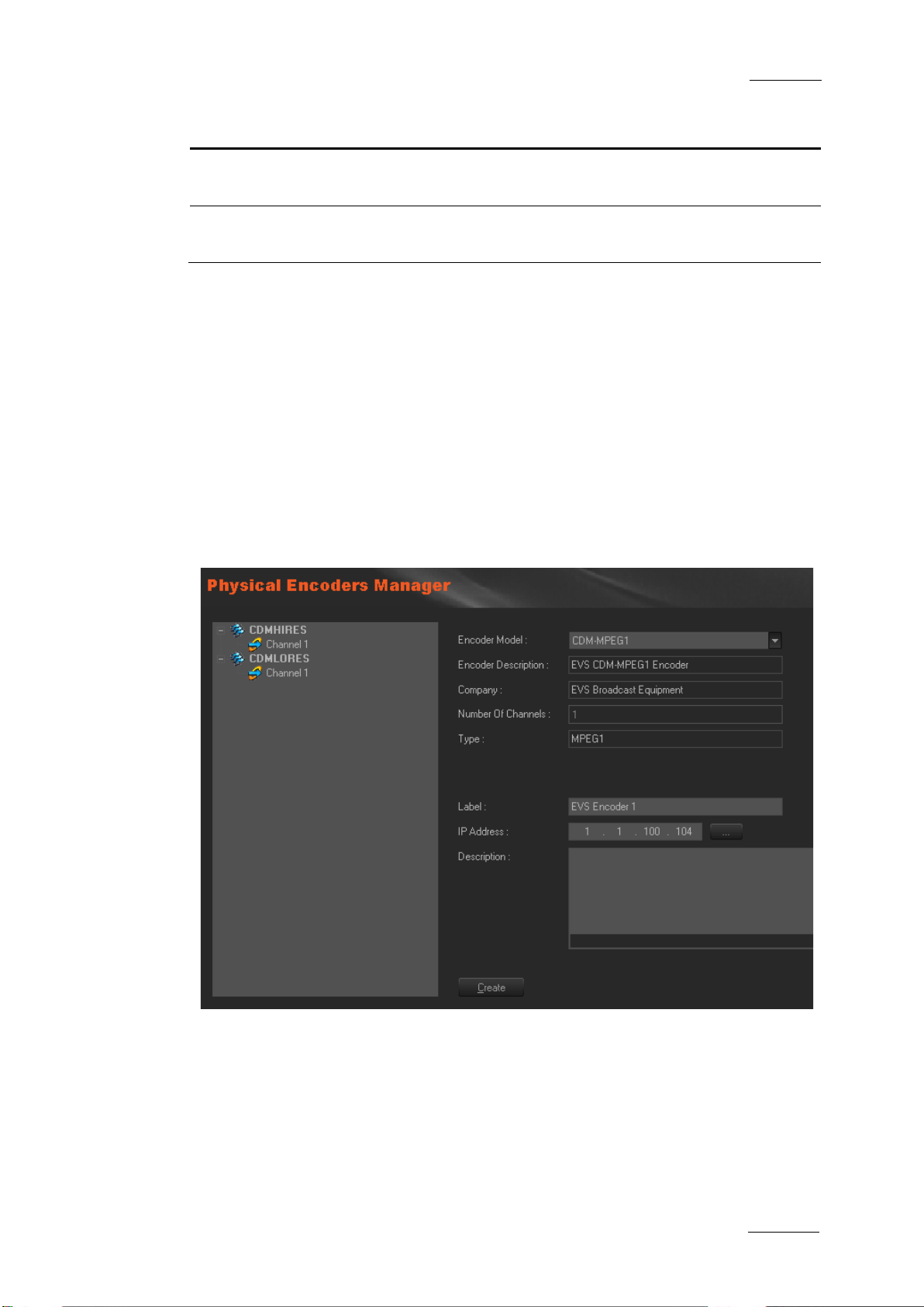
You must define and co nfigure a physical encoder before you can use it.
When you click the Physical Manager button, the Physical Encoders Manager
window is displayed in the Work area, allowing you to define or update encoding
hardware connected to the network (Encoder type, IP address) and the encoding
parameters.
Contextual menus are av ailable for additional operations.
Page 20

Issue 4.2.B
Xedio Suite Version 4.2 - User Manual – Xedio Manager
10
(also called
(also called CDM[3]
placing the pointer over the
3.2.2 CREATING PHYSICAL ENCODER
To create and configure a physical encoder, complete the follo wing fields and then
click on the Create button.
The encoder name is added to th e list on the left side of the window and ‘Channel
1’ appears underneath. A s the XEDIO I/O model is a multichannel encoder, up to 2
channel numbers are di splayed under the encoder name.
Field Description
EVS Broadcast Equipment – June 2012
Encoder Model
Select an encoder model among CDM[1]
CDM-MPEG), CDM[2], XEDIO I/O
PCX3)
Encoder Description Automatically filled at e ncoder model selection.
Company Automatically filled at en coder model selection.
Number of Channels Automatically filled at encoder mode l selection.
Type Automatically filled at en coder model selection.
Label Name you give to the physical encoder, as it will appear
in the list. Preferably choose a name relevant to the job
of the encoder or to its position in the Xedio architecture.
IP Address IP address of the phy sical encoder.
Description Optional text to describe the encoder. This will appear in
a ToolTip when
corresponding encoder name in the list on the le ft.
Page 21
Xedio Suite Version 4.2 - User Manual – Xedio Manager
EVS Broadcast Equipment – June 2012
Issue 4.2.B
11
ll be
Number of B frames between two P frames (typically 2).
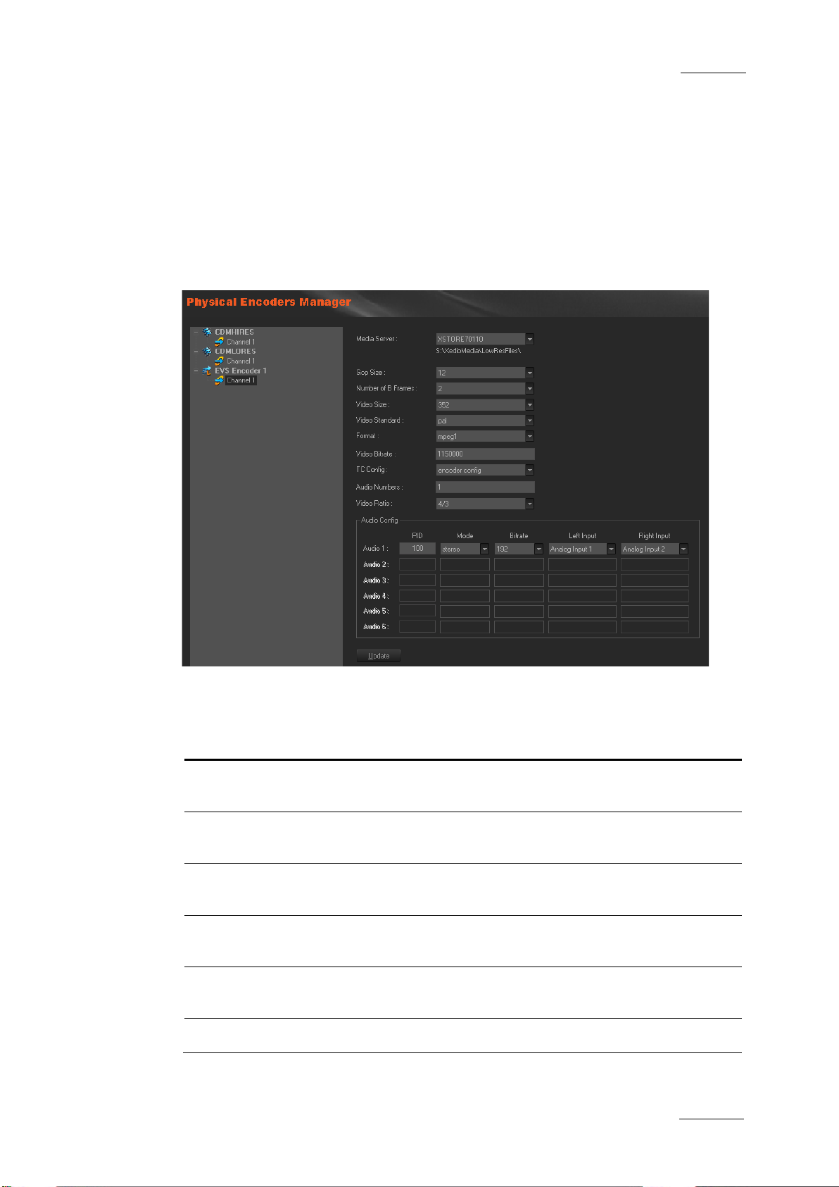
3.2.3 SETTING UP THE ENCODING PARAMETERS
Select a channel (’Channel 1’, or ‘Channel 2’ with CDM[3] PCX3) to set the
encoding parameters.
The encoding parameters fields displayed on the right depend on the encoder
model.
CDM-MPEG ENCODING PARAMETERS
The available paramete rs for CDM[1], also called CDM-MPEG, are the following:
Setting Description
Media Server
Gop Size Number of frames between two I pictures (normal setting is
Number of B
Frames
Video Size Width of the picture. Select a value in the list (typically 352
Video
Standard
Format MPEG1
Media storage server where the encoded media files wi
stored.
12). Defines the MPEG file structure to use.
Defines the Gop struct ure to use.
for the lo-res and 72 0 for the hi-res, for a CDM-MPEG2).
Choose PAL or NTSC sta ndard.
Page 22
Issue 4.2.B
Xedio Suite Version 4.2 - User Manual – Xedio Manager
12
Video encoding bitrate, entered as a bit/sec number. For
the timecode is based on the video source signal.
the timecode is taken from the CDM encoder
EVS Broadcast Equipment – June 2012
Setting Description
Video Bitrate
example, 8Mb/s is ente red as 8000000.
TC Config Defines the timecode i nserted in the encoded fi le:
• vitc:
Select vitc for all encoders in a lo-res + hi-res
configuration.
• local time:
local time.
• encoder config: the timecode is managed by the encoder
itself (from the CDM Ma nager application).
Audio
Numbers
Number of audio channe ls to encode and multiplex .
This is related to the audio configuration table tha t defines the
audio parameters for t he encoded file.
Video Ratio Selection between 16/9 and 4/3 formats for encodi ng.
When you have done the required modifications, click on the Update button to
send the new parameters values to the encoder hardwar e.
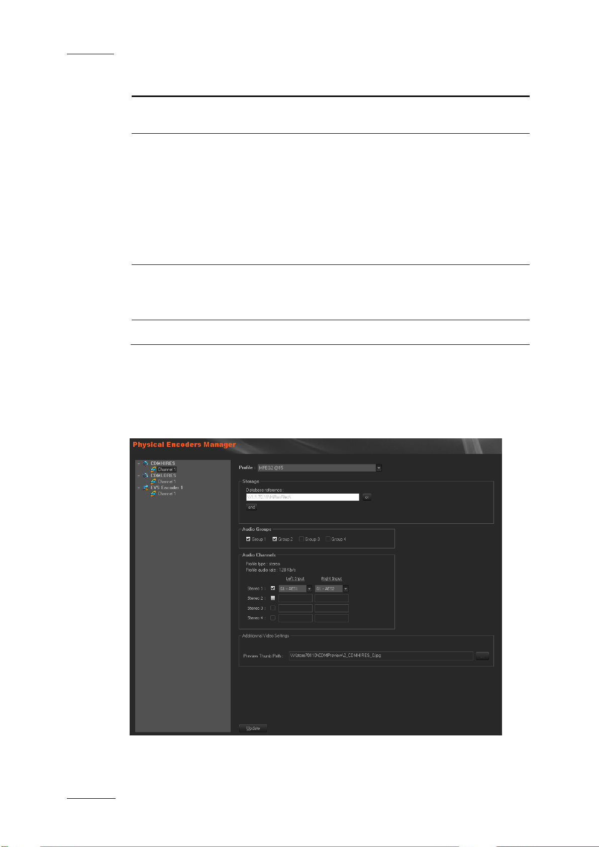
CDM[2] AND CDM[3] ENCODING PARAMETERS
Page 23

Xedio Suite Version 4.2 - User Manual – Xedio Manager
EVS Broadcast Equipment – June 2012
Issue 4.2.B
13
Only two groups of embedded audio can be selected
Preview Thumb
Path of the thumbnail, automatically generated by the
The available parameters for CDM[2] and CDM[3] are the f ollowing:
Setting Description
Profile Encoding profile used by the encoder.
The profiles come from a li st of xml files stored on the storage
server (in the Profiles/CDM2 folder). These files define the
codecs/formats and the ir parameters.
Storage The storage server tha t stores the encoded media files.
Audio Groups This parameter is only available for CDM[2].
simultaneously.
Audio
Channels
Path
The audio sources can be chosen using the drop down lists in
the selected groups.
encoder, during video digitization.
This thumbnail is used in Xedio Ingest Organizer scheduler
and Xedio Manager to p review the source being e ncoded.
3.2.4 MODIFYING THE PHYSICAL ENCODER PROPERTIES
To modify the properties of a physical encoder, select it in the list, enter new
values in the relevan t fields, and click the Update button.
3.2.5 POSSIBLE ACTIONS WITH CONTEXTUAL MENUS
A contextual menu is available when you select an encoder name in the list and
then right-click. The fol lowing options can be se lected:
Menu Item Description
Duplicate Creates a new physical encoder with the same properties
and same encoding parameters. The term ‘duplicated’ is
added next to the new en coder name.
Delete Deletes the encoder co nfiguration and removes it f rom the
list.
A contextual menu is available when you select a channel in the list and then
right-click:
Menu Item Description
Set Label /
Description
Opens a dialog box allowing to update the ‘Channel 1’ or
‘Channel 2’ name or to enter a description.
Page 24
Issue 4.2.B
Xedio Suite Version 4.2 - User Manual – Xedio Manager
14
This will determine the Ingest Organizer workstation which
3.3 LOGICAL MANAGER
3.3.1 INTRODUCTION
When you click the Logical Manager button, the Logical Encoders Manager
window is displayed in the Work area, allowing you to logically group physical
encoders as being part of the same channel. Possible configurations use two
encoders in hi-res and lo-res or one encoder in hi-res only. With a XEDIO I/O
encoder model, lo-res and hi-res are recorded by t he same encoder.
EVS Broadcast Equipment – June 2012
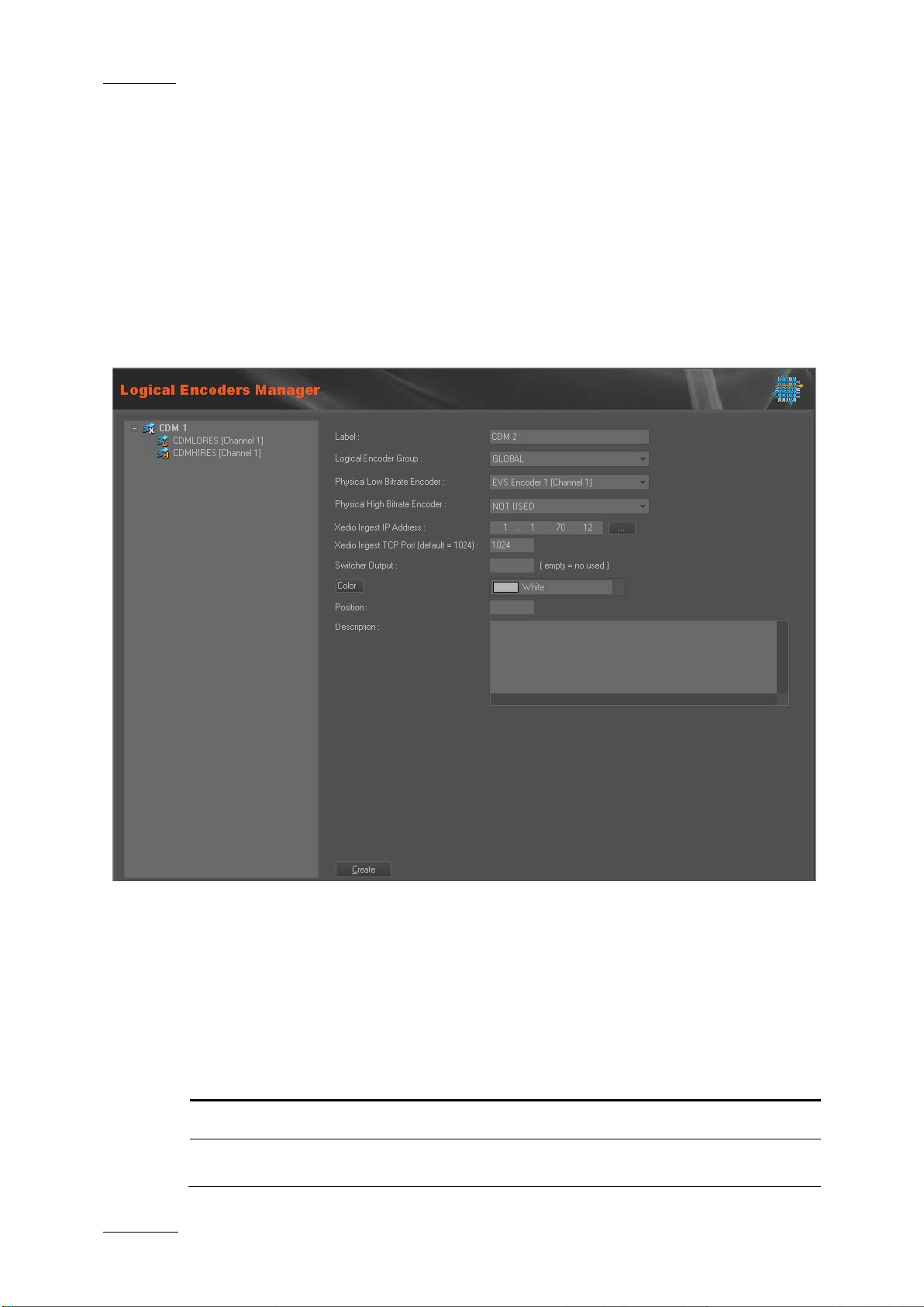
3.3.2 CREATING LOGICAL ENCODER
To create and configure a logical encoder, complete the following fields and then
click on the Create button.
The logical encoder name is added to the list on the left side of the window and
the name of its corres ponding physical encoders a ppears underneath.
Field Description
Label Give a name to the logical encoder.
Logical Encoder Select the group you want to link to the logical encoders.
Page 25

Xedio Suite Version 4.2 - User Manual – Xedio Manager
EVS Broadcast Equipment – June 2012
Issue 4.2.B
15
Group
will see the encoders and this is used to restrict the access
le to all the
encoder model, selecting one of the
Port of the server hosting the Xedio Ingest Organizer
of the encoder channel in the Xedio
Optional text to describe the logical encoder. This will
appear in a ToolTip when placing the pointer over the
Field Description
to some encoders by th e Ingest Organizer.
The GLOBAL group makes the encoders visib
Ingest Organizer works tations.
Physical Low
Bitrate Encoder
Physical High
Bitrate Encoder
Xedio Ingest IP
address
Xedio Ingest TCP
Port
Switcher Output Output of the swi tcher to which the enco der is connected.
Color Background color
Select the low bitrate (if applicable) physical encoder to be
part of the logical e ncoder.
With a XEDIO I/O
physical encoder channels automatically alloc ates the other
channel of the physical encoder to the corresponding low
bitrate or high bitra te field.
Select the high bitrate physical encoder to be part of the
logical encoder.
IP address of the server hosting the Xedio Ingest Organizer
module controlling the encoder.
module.
Scheduler.
The color palette is available by clicking the Color button
and then selecting a color from the drop-down list.
Position Position of the encoder channel in the Xedio Scheduler.
Description
corresponding logical encoder name in the list on the left.
3.3.3 MODIFYING THE LOGICAL ENCODER PROPERTIES
To modify the properties of a logic al encoder, select it in the list, enter new val ues
in the relevant fields, a nd click the Update button.
3.3.4 POSSIBLE ACTIONS WITH CONTEXTUAL MENUS
DELETING A LOGICAL ENCODER
A contextual menu is available when you select a logical encoder name in the list
and then right-click:
Page 26

Issue 4.2.B
Xedio Suite Version 4.2 - User Manual – Xedio Manager
16
Exports the list and configuration of encoders in a
Imports the list and configuration of encoders in a
In the Open window, select the file that contains the
EVS Broadcast Equipment – June 2012
Menu Item Description
Delete Logical
Encoder
Deletes the logical encoder configuration and removes it
from the list.
EXPORTING AND IMPORTING ENCODER PROPERTIES
A contextual menu is available when no encoder is selected and you right-click in
the encoder list area .
Menu Item Description
Export Encoders
readable file (.enc f ormat).
In the Save As window, select the fol der to export the file
to.
Import Encoders
readable file.
encoders list to impor t.
Page 27
Xedio Suite Version 4.2 - User Manual – Xedio Manager
EVS Broadcast Equipment – June 2012
Issue 4.2.B
17
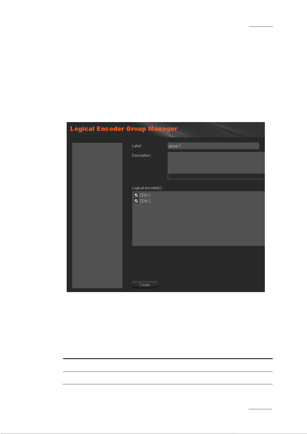
3.4 GROUP MANAGER
3.4.1 INTRODUCTION
When you click the Group Manager button, the Logical Encoder Group Manager
window is displayed in the Work area, allowing you to group together multiple
logical encoders.
A group of encoders will then be visible only to a predefined Xedio Ingest
Organizer workstation. Indeed, at first run of Xedio Ingest Organizer, the group
membership is set.
3.4.2 CREATING A GROUP OF LOGICAL CHANNELS
To create a group of logical encoders, complete the followin g fields and then click
on the Create button.
The group name is adde d to the list on the left side of the window.
Field Description
Label Give a name to the group of logical e ncoder.
Description Optional text to describe the group of logi cal encoders.
Page 28
Issue 4.2.B
Xedio Suite Version 4.2 - User Manual – Xedio Manager
18
workstation to
EVS Broadcast Equipment – June 2012
Field Description
Logical Encoders Select the logica l encoders to group together.
Note 1
A group of logical channels rest ricts the amount of available channels for
specific Xedio Inges t Organizer workstations. Ther e is one default group,
called GLOBAL, that allows a Xedio Ingest Organizer
“see” all channels whe n it is selected.
Note 2
To finalize encoders configuration, it is necessary to store the CDM
encoders mapped drive in the database (see section 6.2.4 ‘Setting the
CDM Encoder Mapped Drive’ on page 39)
3.4.3 DELETING A GROUP OF ENCODERS
To be able to delete a group of encoders, you first need to clear the logical
encoders boxes and click the Update button.
Then, right-clicking the group name will show you a contextual menu with the
Delete option.
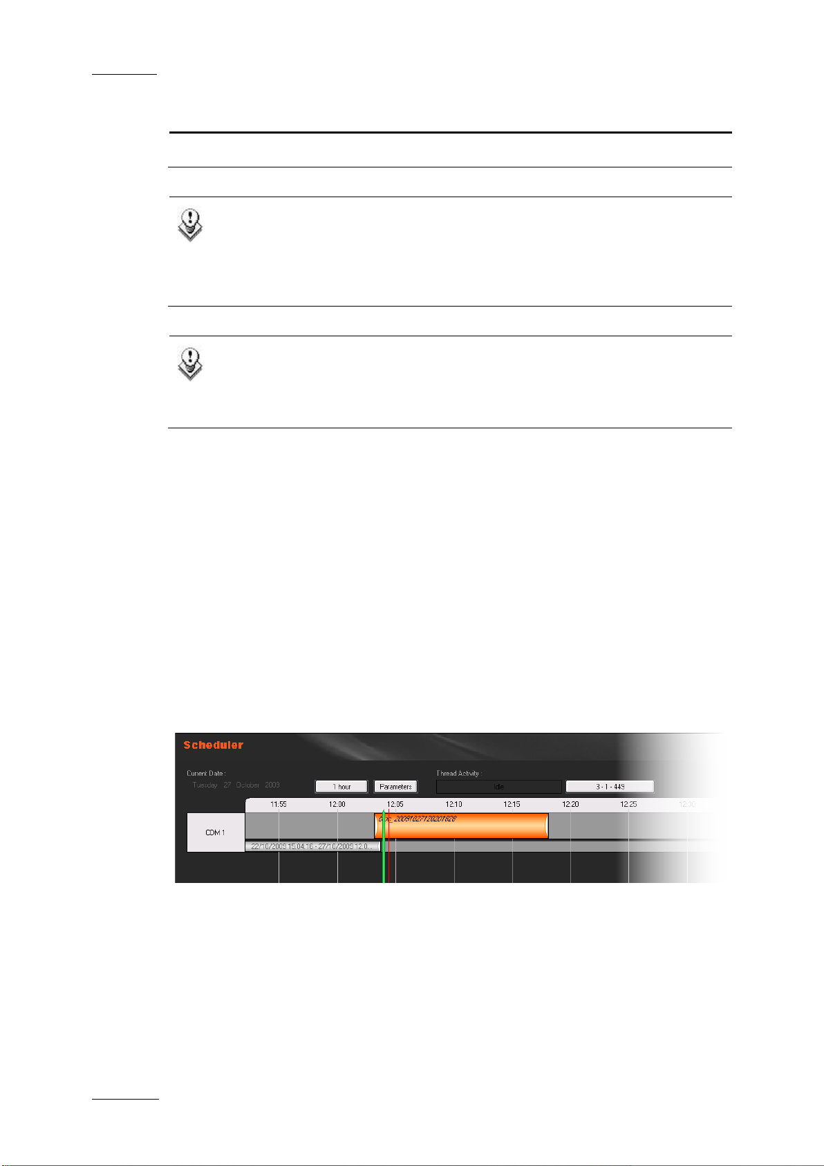
3.5 SCHEDULER
When you click the Scheduler button, the Scheduler window displays blocks
corresponding to the scheduled ingests already planned for encoding by all the
logical encoders.
As this function is the same as the one avail able in Xedio Ingest Or ganizer, please
refer to the user manual of this applicati on for more details.
Page 29
Xedio Suite Version 4.2 - User Manual – Xedio Manager
EVS Broadcast Equipment – June 2012
Issue 4.2.B
19
3.6 PREVIEW
When you click the Preview button, the Preview window displays simultaneously
the video currently u nder processing and encoding at all encoders inputs.
The only available par ameter is the Refresh Rate defined in seconds.
Page 30
Issue 4.2.B
Xedio Suite Version 4.2 - User Manual – Xedio Manager
20
Defines the parameters of the web services used to
4.1 INTRODUCTION
Xedio “Add-On” for EVS Video Server is based on LinX protocol and XT Gateway.
The LinX Application Programming Interface is an integrated API used to access
the EVS family video s ervers through Ethernet/I P connection.
Xedio can access EVS video server disks (e.g. XT[2], XS) and use the media
stored on EVS server thanks to XTGateway, provided that they have previously
been configured. Xedio will then be able to see, display, search and access clips
and record trains on EVS video servers. New clips could be created in CleanEdit
from EVS video servers.
EVS Broadcast Equipment – June 2012
4. LinX and
Direct Access
Two items are available in the LinX category. T hey are detailed in the tab le below.
Item Description
EVS Video Server Defines setup parameters for an EVS video server which
will be used by CleanEdit to see, display, search and
access clips and recor d trains.
EVS Video Server
Group
All the steps below must be followed.
interact between Xedio and the EVS video servers .
4.2 GENERAL CONFIGURATION PARAMETERS
The following parameters must be defined from Softwares > Parameter Profiles >
General > General tab:
• Notification C enter Address: set the IP ad dress with port 48888.
Example: 172.22.23.9:4 8888
Page 31
Xedio Suite Version 4.2 - User Manual – Xedio Manager
EVS Broadcast Equipment – June 2012
Issue 4.2.B
21
• XedioBroker Address: se t the IP address with port 8762.
Example: 172.22.23.9:8 762
4.3 EVS VIDEO SERVE R
4.3.1 INTRODUCTION
All the EVS Video Servers you want to access through LinX protocol must be
referenced in this ca tegory.
The Discover button helps you to “discover” automatically all the EVS Video
Server available on your network. If a server does not appear in the discovery,
you can try to restart the server or check the network path between the local
machine and your server (e.g. mutlicast shall be enabled), If it is still not
discovered, then conf igure the server manually.
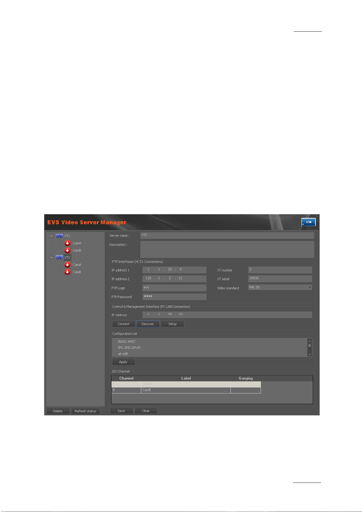
When you click the EVS Video Server button, the EVS Video Server Manager
window is displayed in the Work area.
Page 32

Issue 4.2.B
Xedio Suite Version 4.2 - User Manual – Xedio Manager
22
Displays the list of configurations available from the
4.3.2 EVS SERVER PARAMETERS
To set EVS video server parameters, complete the following fields and then click
on the Save button.
Field/Button Description
Server Name Name of t he server to be accessed by Xedio, as you want
it to be displayed in the interface.
Description Optional text to describe the EVS Server.
FTP Interfaces (HCTX Connections)
IP Address 1 FTP IP address 1 of the EVS server you want to connect
to (mandatory).
IP Address 2 FTP IP address 2 of the EVS server you want to connect
to (optional).
EVS Broadcast Equipment – June 2012
FTP Login Login ID d efined on the EVS server (e.g. evs).
FTP Password Password defined on the EVS server (e.g. evs) .
Control & Management Interfa ce (PC LAN Connection)
IP Address PC LAN IP address of the EVS server you want to connect
to (mandatory).
Connect Checks the connection with the selected EVS server.
Discover Opens a window which lists the EVS video servers from
the network and their corresponding PC LAN IP address.
Setup Opens a dialog box which allows to set the AVSP
guardbands length of clips created wi th LinX (e.g. 5 sec 0
frame).
Configuration List
server.
Apply Applies the selected configuration.
Page 33

Xedio Suite Version 4.2 - User Manual – Xedio Manager
EVS Broadcast Equipment – June 2012
Issue 4.2.B
23
Field/Button Description
I/O Channel Displays the list of recorder channels from the selected
EVS server.
Button Description
Delete Deletes the selected EVS serve r from the tree structure.
Refresh Checks whether the EVS video serv er is reachable. If yes,
the server configuration is retrieved. If not, the server
name and server icon a re displayed in red.
Save Saves the parameters entered for the serve r.
Clear Clears the parameters e ntered for the server.
4.3.3 HOW TO GANG RECORDER CHANNELS
You can gang several recorder channels from an EVS video server. To do so,
proceed as follows:
1. Select several recorder channels in the I/O Chann els area,
2. Right-click the list.
3. Select Gang.
The ganged channels ar e mentioned in the Gangin g column.
4.3.4 POSSIBLE ACTIONS WITH CONTEXTUAL MENUS
A right-click on a server dis plays a contextual menu wit h the following option:
Menu Item Description
Delete XT Deletes the selected EVS server from the t ree structure.
Page 34

Issue 4.2.B
Xedio Suite Version 4.2 - User Manual – Xedio Manager
24
of the machine hosting the LinxAdapter
Keep 80 for TCP Port and
4.4 EVS VIDEO SERVE R GROUP
When you click the EVS Video Server Group button, the EVS Vide o Server Group
Manager window is displ ayed in the Work area.
EVS Broadcast Equipment – June 2012
To set a group of EVS video server, complete the following fields, select the
servers you want to gr oup and then click on the Create button.
Field Description
Label Name you want to give to the group of servers.
Description Optional text to desc ribe the group of EVS Serve rs.
LinxAdapter IP address
software, used to manage the Linx notifications from the
EVS video server to Xedio.
keep the soap string unchanged.
LinxAdapter Backup Not used. Keep 0.0.0.0.
LinxOutAdapter IP address of the machine hosting the LinxOutAdapter
software, used to manage the Linx commands sent from
Xedio to the EVS video server. Keep 80 for TCP Port and
keep the soap string unchanged.
Page 35

Xedio Suite Version 4.2 - User Manual – Xedio Manager
EVS Broadcast Equipment – June 2012
Issue 4.2.B
25
in the EVS Video
Field Description
EVS video servers
List of EVS video servers defined
Server tab. Select the servers you want to include in the
group. All t he EVS servers which must be seen and could
be used in CleanEdit m ust be assigned to a group.
Mandatory.
Page 36

Issue 4.2.B
Xedio Suite Version 4.2 - User Manual – Xedio Manager
26
5.1 INTRODUCTION
External devices can be connected to the Xedio Suite. Their parameters are
configured from the Ma chines tab.
Four items are available in the Machines category. They are detailed in the table
below.
EVS Broadcast Equipment – June 2012
5. Machines
Item Description
VTR Manager Defines setup parameter s for a controlled VTR.
Switcher Manager Defines setup parameters for a switcher connected to the
system.
Archive Servers Defines setup parameters for a server used to archive
media.
XFile Manager Defines setup parameters for an XFil e used for rendering.
IPDirector Defines setup parameters to use information coming from
IPDirector API.
Page 37

Xedio Suite Version 4.2 - User Manual – Xedio Manager
EVS Broadcast Equipment – June 2012
Issue 4.2.B
27
IP address of the server hosting the Xedio Ingest
5.2 VTR MANAG ER
A VTR can be used as a source of ingest. The VTR video output must be
connected to the encoder video input.
When you click the VTR Manager bu tton, the VTR Manager window is disp layed in
the Work area.
To set VTR parameters, complete the following fields and then click on the Save
button.
Field Description
ID Number automatically allocated by the system when you
save the VTR configura tion.
Label Name you give to the V TR device.
Description Optional text to desc ribe the VTR device.
Xedio Ingest
Organizer IP
Organizer module contro lling the VTR to be used.
Serial COM Port Port used by the workstation when sending data and
transport control comman ds to the VTR (in RS-422).
Switcher Input Switcher device to which the video source of the VTR is
connected. Leave this field blank if you do not have any
switcher control devic e supporting Xedio protoc ol.
Page 38

Issue 4.2.B
Xedio Suite Version 4.2 - User Manual – Xedio Manager
28
5.3 SWITCHER M ANAGER
When you click the Switcher Manager button, the Switcher Manager window is
displayed in the Work area.
EVS Broadcast Equipment – June 2012
You can indirectly control a switcher through the system. If the T ransmit Switcher
Info field is checked, Xedio Ingest Server application transmits the switching
information over the Ethernet network to a dedicated software device before
starting any recording. T his device will manage the audio and video routing at the
switcher with regard to i ts brand and protocol, and send an acknowled gement back
to Xedio Ingest Server within a determined delay i n order to start the enco der(s).
To set switcher parameters, complete the following fields and then click on the
Apply button.
Field Description
Transmit Switcher
Info
Switcher Config Host
Enables/Disables the use of a software device to control
the switcher(s)
IP address of the sof tware device to access to.
IP
Switcher Config Host
Port number where to se nd the switching informat ion.
Port
Wait For Host
Delay for the “acknowl edge” coming from the dev ice.
Response TimeOut
(in sec.)
Note
When timeout delay is reached, Xedio Ingest
Server aborts the reco rding process.
Page 39

Xedio Suite Version 4.2 - User Manual – Xedio Manager
EVS Broadcast Equipment – June 2012
Issue 4.2.B
29
Possible answers following a
Possible answers following a
The protocol used between Xedio Ingest Server and the “switching device” uses
the following commands:
Commands sent from CleanGes t Server
Description
to the switching device
<ConnectPorts InPort="x" OutPo rt="y"/> Used before st arting a record
<ReleasePorts InPort="x" OutPo rt="y"/> Used at the end of a record.
The answers received fr om the device must be as follows:
Received from the softw are device Description
<ConnectOK/>
<ConnectFailed/>
“ConnectPorts” command.
<ReleaseOK/>
<ReleaseFailed/>
“ReleasePorts” command.
<CmdErr/> Error status
Page 40

Issue 4.2.B
Xedio Suite Version 4.2 - User Manual – Xedio Manager
30
5.4 ARCHIVE SERVER MANAGER
When an Archive Server is attached to a Xedio installation, it must be referenced
in the database.
When you click the Archives Servers Manager button, the Archive Servers
window is displayed in the Work area.
EVS Broadcast Equipment – June 2012
To set archive server parameters, complete the following fields and then click on
the Save button.
Field Description
ID Number automatically allocated by the system when you
save the Archive Serve r configuration.
Label Name you give to the A rchive Server.
Description Optional text to desc ribe the Archive Server .
IP Address IP address of the archive serve r.
Is default When selected, the current archive server is used by
default.
Page 41

Xedio Suite Version 4.2 - User Manual – Xedio Manager
EVS Broadcast Equipment – June 2012
Issue 4.2.B
31
5.5 XFILE MANAGER
XFile can be used to receive and send media in file format or for the rendering of
files to an EVS video server.
When you click the XFile Manager button, t he XFile Manager window is displayed
in the Work area.
To set XFile parameters, complete the following fields and then click on the Save
button.
Field Description
ID Number automatically allocated by the system when you
save the XFile configu ration.
Label Name you give to XFile.
Description Optional text to desc ribe the XFile.
XFile IP Address IP address of the machine hosting XFile software.
Root XML Path Location where an XML file is sent by Xedio to request a
job.
Media Path Location where the media is stored before being treated
by XFile.
Default XT EVS video server number used by default to store media
files treated by XFile.
Default Page EVS server page number used by default to store media
Default Cam EVS server cam number used by default to store media
files treated by XFile. If the field is left empty, the first
available place will be used.
files treated by XFile. If the field is left empty, the first
available place will be used.
Page 42

Issue 4.2.B
Xedio Suite Version 4.2 - User Manual – Xedio Manager
32
5.6 IPDIRECTOR
It is possible to syn chronize the Xedio databas e with the IPDirector da tabase.
The IPD Gateway is a Windows service used to synchronize database information
from IPDirector to Xedio. It subscribes to IPDirector Notifica tion Server.
The IPDirector Notification Server is an IPDirector API which is used to notify the
gateway when modificati ons are done in the IPDire ctor database.
Important
When the IPD Gateway has been installed, it must be configured in
Xedio Manager and the IPD nearlines must be configured in the Xedio
Media Servers of Xedio Manager before you start the IPD Gateway
services.
When you click the IPDirector button, the IPDirector window is displayed in the
Work area.
EVS Broadcast Equipment – June 2012
To set IPDirector parameters, complete the following fields and then click on the
Update button.
Field Description
IPDirector Gateway
IP Address IP address of the machine where the IPDirector gateway
is installed.
Page 43

Xedio Suite Version 4.2 - User Manual – Xedio Manager
EVS Broadcast Equipment – June 2012
Issue 4.2.B
33
IP address of the machine where the IPD database is
Field Description
TCP Port IPD gateway TCP port (default is 808 0)
Domain User ‘.\<Windows Domain User with Admin rights>’
Domain Password Windows Domain Password for this user
IPDirector Notification Server
IP Address IP address of the machi ne where the IPD API is in stalled.
TCP Port IPD API TCP port.
Login Login for the IPD Notification Server
Password Password for the IPD Noti fication Server
Create When selected, the ‘create’ operations in IPDirector are
notified.
Update When selected, the ‘update’ operations in IPDirector are
notified.
Delete When selected, the ‘deletee’ operations in IPDirector are
notified.
IPDirector Database
IP Address
installed.
Database Name Name o f the server where the IPD data base is located.
Login IPD databa se username.
Password IPD database password.
Each time the configuration is modifying, click the Full Resync button to force a
full resynchronization from IPDirector to Xedio. A confirmation dialog box then
opens where users enter the dates interval to be taken into account for the
resynchronization.
Page 44

Issue 4.2.B
Xedio Suite Version 4.2 - User Manual – Xedio Manager
34
EVS Broadcast Equipment – June 2012
5.7 MODIFYING OR DELETING AN EXTERNAL DEVICE
To modify the properties of one of the previous external devices, except a
switcher, select it in the list, enter new values in the relevant fields, and click the
Update button.
To delete one of the previous external devices, except a switcher, select it in the
list, right-click and sel ect Delete from the contextu al menu.
Page 45

Xedio Suite Version 4.2 - User Manual – Xedio Manager
EVS Broadcast Equipment – June 2012
Issue 4.2.B
35
Allows to define the media storage server(s) and to
Manages the animated transition graphics (RTD’s)
anages the media files within the database and the
6.1 INTRODUCTION
From the Media category you can define the media storage tree structure and
media classes, you can import and manage media file s.
Five items are available in the Medias category. They are detailed in the table
below.
6. Media
Item Description
Servers
create its sub-folders (multiple storage servers may be
defined).
Class Manager Allows to define a Class List to categorize the stored
media.
Media Importer Allows to import media fil es into the storage server and to
create a reference to the files within the data base.
RTD Manager
referenced in the dat abase.
Manager M
storage server.
Page 46
Issue 4.2.B
Xedio Suite Version 4.2 - User Manual – Xedio Manager
36
6.2 MEDIA SERVERS
6.2.1 INTRODUCTION
A Media Server is the l ocation where all the media used withi n a Xedio installation
will be stored.
When you click the Media > Servers button, the Media Servers window is
displayed in the Work area, allowin g you to define a media se rver.
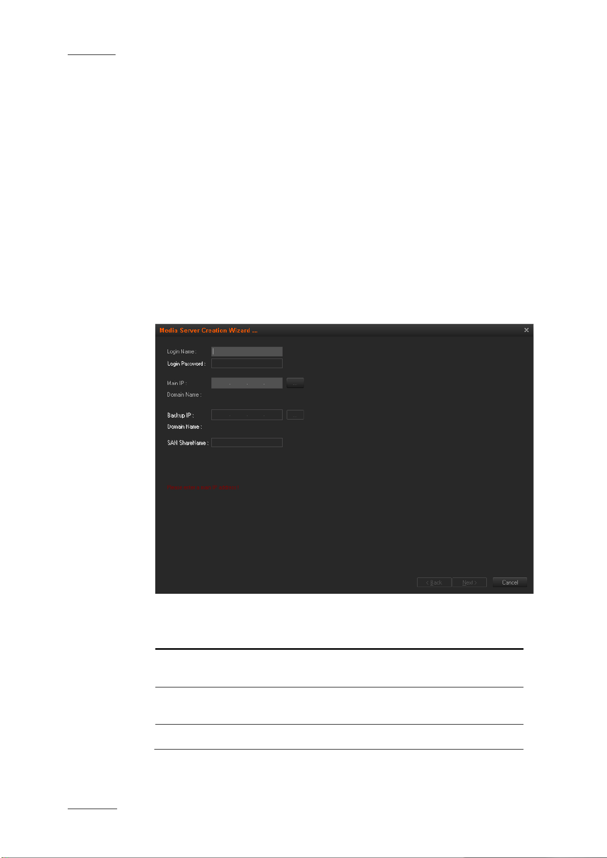
6.2.2 ADDING A MEDIA SERVER
To add a media server, proceed as follows:
1. Right-click in the Media Server window and select New Media Server in the
contextual menu. A wiz ard opens.
EVS Broadcast Equipment – June 2012
2. Complete the fields descr ibed in the following tabl e:
Field Description
Login Name Login name defined for the media server in its
configuration paramete rs.
Login Password Login password defined for the media server in
its configuration par ameters.
Main IP IP address of the serv er used for media storage .
Page 47

Xedio Suite Version 4.2 - User Manual – Xedio Manager
EVS Broadcast Equipment – June 2012
Issue 4.2.B
37
Domain Name Field automatically filled when an IP address is
entered
Backup IP IP address of the backup storage server, when a
redundant network is used.
3. Click Next.
The next page displays the drives capacity of the new media server.
4. Click Next.
5. Select the drive(s) for the storage and enter a base path for the sub-folders
that will be created by the system.
6. Click Next.
7. Type a name for the server in the Label field.
8. Click Finish.
The tree structure of the media server is di splayed.
6.2.3 CONTEXTUAL MENUS
A contextual menu is availabl e when you select a media server in the list a nd then
right-click:
Menu Item Description
New Media Server Adds a media serve r storage: displays the folders present
Rename Media
Server
in the path selected for use as media server.
Allows to update the m edia server label.
Page 48

Issue 4.2.B
Xedio Suite Version 4.2 - User Manual – Xedio Manager
38
view in the Media Servers
created in the system. This tells the system to use a
and sets the HIRES folder as
Removes the media folder from the Media Servers
EVS Broadcast Equipment – June 2012
Menu Item Description
Delete Media Server
Deletes the media server
window.
Modify Media Server
Description
Opens the Media Server Modification window allowing to
update the label or d escription of the media se rver.
Media File Cleaner Opens the Media File Cleaner windo w. Refer to section 12
‘Media File Cleaner’ o n page 134 for more informa tion.
A contextual menu is available when you select a folder in the list and then rightclick:
Menu Item Description
New Media Server Adds a media s erver storage: displays the fol ders present
in the path selected for use as media server.
Default ‘Folder Name
Files’ Directory
Sets the selected folder as default folder for the type of
files (bitmaps, video files, thumbnails etc…). The folder
icon is then green.
This is only necessary when multiple storage servers are
specific storage server for some files and another server
for other files. Th e Default folders may be chang ed at any
time without losing pr eviously stored material.
Example: for the HIRES folder, the option is Default
‘HiResFiles’ Directory
default for the hi-re s files.
Delete Media
Directory
window.
Collect Media Displays t he list of media present in t he selected folder.
Media File Cleaner Opens the Media File Cleaner windo w. Refer to section 12
‘Media File Cleaner’ o n page 134 for more informa tion.
Page 49
Xedio Suite Version 4.2 - User Manual – Xedio Manager
EVS Broadcast Equipment – June 2012
Issue 4.2.B
39
6.2.4 SETTING THE CDM ENCODER MAPPED DRIVE
The physical encoder is usually configured to store the encode d files on a specific
mapped drive, usually called “G” or “H”. This mapped drive letter also has to be
stored in the databas e in the CDM Mapping column.
To set or change the enc oder mapped drive, proce ed as follows:
1. In the Medias Servers window, click twice (not a double cli ck, click then wait
and click again) the mapped drive letter related to the requested server in
the CDM mapping column.
2. Select the requested CD M mapped drive from the drop-d own list.
The encoder mapped driv e has been set or changed.
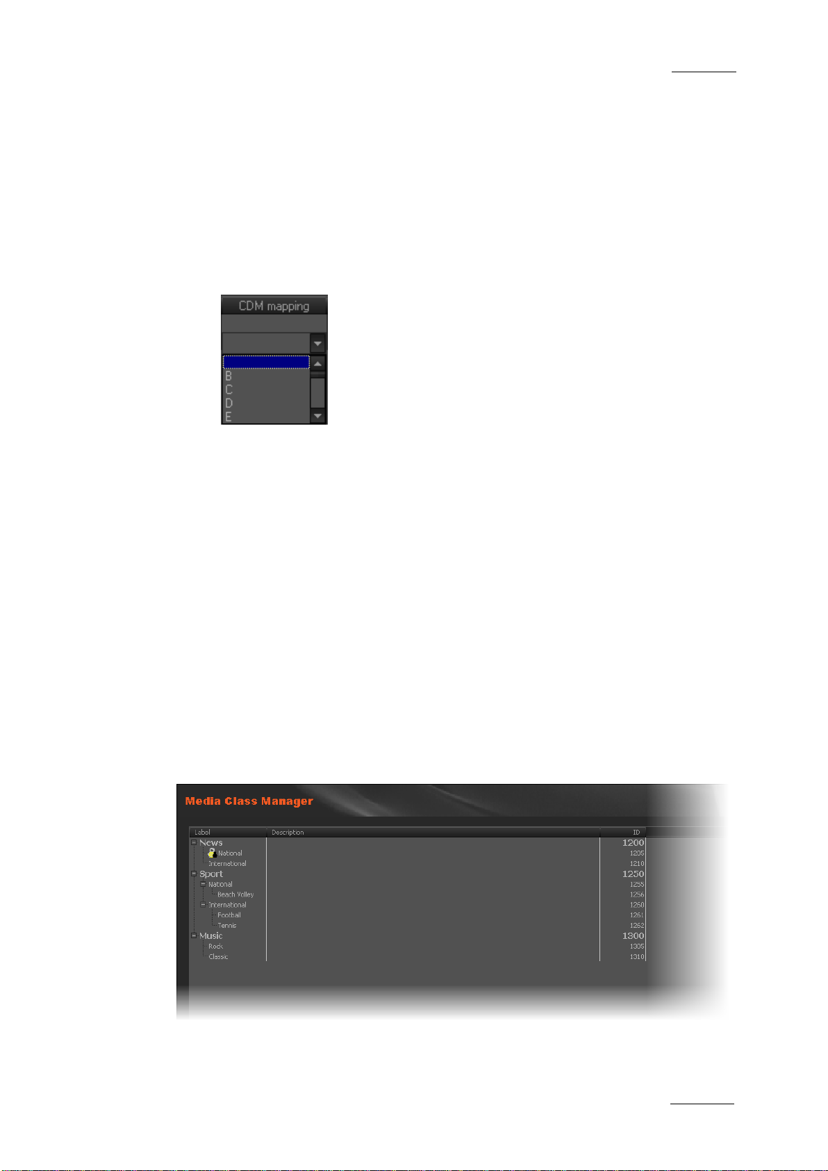
6.3 CLASS MANAGER
6.3.1 INTRODUCTION
The Class Manager tool is used to define and manage the ClassList. Classes
categorize the media and the virtual media. They are mainly used in the database
lists from the Xedio Suite to perform search on media. Media are assigned to
classes through the Xedio applications such as Xedio Ingest Organizer, Xedio
Importer, Xedio AutoFi le Importer or Xedio Browse applications.
When you click the Class Manager button, the Media Class Manager window is
displayed in the Work area, allowing you to create new media classes and subclasses.
Page 50

Issue 4.2.B
Xedio Suite Version 4.2 - User Manual – Xedio Manager
40
class so users
6.3.2 POSSIBLE ACTIONS WITH CONTEXTUAL MENUS
A contextual menu is available w hen no class is selected and you right-click in the
Media Class Manager win dow.
Menu Item Description
New Root Creates a new class of media.
A contextual menu is available when you select a Class in the list and then rightclick:
Menu Item Description
New Root Creates a new class of media.
New Child Creates a new sub-class of media.
Rename Allows to rename the s elected class or sub-class.
EVS Broadcast Equipment – June 2012
Modify Opens the Modify Class window allowing to update the
label or description of the selected class or sub-class.
Delete Deletes the selected c lass or sub-class.
Hidden State Hides/Unhides the selected class or sub-
cannot/can use it.
6.4 MEDIA IMPORTER
The Media Importer is th e tool used to import, into the Xedio database, media that
have already been recorded and are in a file format that can be used by Xedio.
P2, XDCAM and XDCAM EX, music, graphics or existing mpeg and dv files are
some examples.
The Xedio Importer is available as:
• a separate appl ication
• as a module buil t in CleanEdit, and availa ble in the Media Importer t ab.
• as a module built in Xedio Manager, and available in the Media category,
Media Importer tool.
When you click the Media Importer button, the Media Importer window is
displayed in the Work area. It pre sents different sub-tabs to set the paramet ers for
different types of media to be imported into the system, such as:
• XDCAM, XDCAMEX, P2 and CANON tabs
To import media files recorded on Sony XDCAM and XDCAMEX, Panasonic P2
and CANON cameras
• Video/Audio /Stills tab
To import media files, images or audio files
Page 51

Xedio Suite Version 4.2 - User Manual – Xedio Manager
EVS Broadcast Equipment – June 2012
Issue 4.2.B
41
• RTD tab
To import video contai ning transitions
• EVS Se rver tab
To import media files available on an EVS server on the same network as the
Xedio suite. In this case, Xedio does not import the file content into the Xedio
storage system, but creates a reference to the server files in the Xedio
database.
Refer to the Xedio Importer user manual for a comprehensive description of the
tabs and fields.
Page 52

Issue 4.2.B
Xedio Suite Version 4.2 - User Manual – Xedio Manager
42
@50, HD 1080i
@59,94, HD 1080p @50, HD 1080p
6.5 RTD MANAGE R
6.5.1 INTRODUCTION
When you click the RTD Manager button,the RTD Manager window is displayed in
the Work area, allowing you to import or manage the tran sition sequences. The list
displays the availabl e effects stored in the sy stem.
6.5.2 POSSIBLE ACTIONS WITH CONTEXTUAL MENUS
EVS Broadcast Equipment – June 2012
A contextual menu is availabl e when no RTD is selected and you right-click in the
RTD Manager window.
Menu Item Description
Import Imports a transition effec t.
A contextual menu is available when you select a RTD in the list and then rightclick:
Menu Item Description
Import Imports a transition effec t.
Preview Allows to preview the selec ted transition effect.
Edit Opens the Update RTD Label window allowing to update
the label or descript ion of the selected effect.
Delete Deletes the selected effect from the da tabase. It can only
be removed if it is not already used in an edit, otherwise,
an error message will o ccur.
Video Standard Allows to select a video standard among PAL SD, NTSC
drop SD, HD 1080i @50, HD 720p
@59,94, HD 720p
@59,94.
Used by Opens a window to show in which projects the selected
media is used in:
Page 53

Xedio Suite Version 4.2 - User Manual – Xedio Manager
EVS Broadcast Equipment – June 2012
Issue 4.2.B
43
6.6 MEDIA MANAG ER
6.6.1 INTRODUCTION
The Media Manager tool is designed to give an overview of the database content,
to edit some media properties and to delete media files from the database and
from the storage server(s). Different search tools can be applied to the database
content to help users to find specific media.
Note
Only items that are not used (not locked) in any user project and not
used to create virtual media and/or clip can be deleted; otherwise, an
error message will occur.
The media items displayed in the Media Manager window are all the media items
corresponding to the filters or search tools applied.
When you click the Media > Manager button, the Media Manager window is
displayed in the Work area.
The upper part of the Work area gives access to the di fferent filters which can be
applied to the media list.
At least two tabs exi st on the left of the Medi a Manager window.
• The Filter 0 tab: The element grid displays the list of all media present in the
database, or it retur ns the result of a sear ch applied to the list.
Page 54

Issue 4.2.B
Xedio Suite Version 4.2 - User Manual – Xedio Manager
44
media can be set as treated when virtual media have
the flag in the
16/9, and unknown. This only affects the flag in the
• The Today tab: the element grid shown the media with ‘creation dat e = today’.
Additional tabs are displayed when the users have saved filters applied to the
database. Refer to sec tion ‘Using Saved Filters’ on page 56 for more detail s.
Media items are displa yed in columns.
6.6.2 ELEMENTS GRID
DISPLAYED COLUMNS
It is possible to re-arrange the columns order, and to add or remove some
columns.
Right-clicking on any of the column headings displays a contextual menu. The
Choose Displayed Columns option opens the Select Visible Columns window
allowing you to choose the columns you want to be displayed in the element gr id.
The column width and order can be adjusted using standard computer commands
and drag and drop tech niques.
EVS Broadcast Equipment – June 2012
ELEMENT CONTEXTUAL MENU
A contextual menu is a vailable when you right-click on an item in t he list.
Menu Item Description
Published State Allows the selection of a sub-menu to change the publish
state of the media between Published and Not
Published. A published media will be displayed in the
database lists of all the software and thus available for
use.
Treated State Allows the selection of a sub-menu to change the treated
state of the media between Treated and Not Treated. A
been created from this media in X edio Browse.
Deleted State Allows the selection of a sub-m enu to change the deleted
state of the media be tween Deleted and Not Deleted.
Video Standard Allows to change the metadata for the media to PAL or
NTSC and vice versa. This only affects
metadata and does not affect the media (to allow for a
correction in the dat a only).
Video Ratio Allows to change the metadata f or the media between 4/3,
metadata and does not affect the media (to allow for a
correction in the dat a only).
Media File(s) Status Allows the selection of sub-menu to change the status of
the low bitrate file or the high bitrate file between Rec
Done, Imported, Rec Error, Archived, ArchiDel,
Restored, Deleted and Imported Erro r.
Page 55

Xedio Suite Version 4.2 - User Manual – Xedio Manager
EVS Broadcast Equipment – June 2012
Issue 4.2.B
45
Displays the properties for the selected media. If a
Generate Low Resolution Media
Menu Item Description
Set Audio Track
Assignment
Allows to set or update the audio track assignment for
selected media (8 audio or 5.1). Refer to section ‘How to
Define New Default Audio Channel Assignment’ on page
76 for explanation.
Properties
default metadata profile has been defined for the media, a
metadata tab is displayed and allows to modify the media
metadata values.
Delete Media &
See section 6.6.4 ‘Delete & Pur ge’ on page 57.
Purge
Force Delete Deletes a media with all the references of its use in the
database. If it is used in an edit , this will cause “holes” in
the edit. This option must be used very cautious ly.
Play Opens a new Player window to al low the low bitrate file or
the high bitrate file to be browsed.
Media Analyzer Opens a Timecode Extractor window showing an analysis
of the selected file .
MOS Publication Allows to send a notification to the news ro om system.
Merge This option is used to associat e a lo-r es media to a hi-res
media.
Opens the Get Lowres File window allowing you to browse
for the lo-res file.
Generate Low
Resolution Media
File
Generates missing lo-res media fi le from the hi-res media
file. Refer to section ‘
Files’ on page 46.
Retrim In case the TC IN or TC OUT of a media hi-res and lo-res
files differ, this option will automatically adjust both files
to the same TC range.
Create Missing
Thumbnails
This option creates thumbnails in the Thumbnail IN and
Thumbnail OUT columns of the Work area.
Page 56

Issue 4.2.B
Xedio Suite Version 4.2 - User Manual – Xedio Manager
46
If the Do this for all selected media option is selected, the check will
EVS Broadcast Equipment – June 2012
Menu Item Description
Used By Opens a window to show in which projects and edits the
selected media is used in:
GENERATE LOW RESOLUTION MEDIA FILES
When several files are selected from the list and you select the Generate Low
Resolution Media File option, se veral cases can occur.
1. Some hi-res files are not present on the Media server (they could be offline
or ARCHIDEL)
A popup window is displayed and lists those missing files. You are asked
whether you want to co ntinue.
• Click YES to generate only lo-res files corresponding to existing hi-res
files
• Click NO to cancel the oper ation.
2. The hi-res files are online and at least one lo-res file already exists on the
Media server or is ‘ARCHIDEL’.
A popup window is displayed and mentions that ex isting file. You are asked
whether you want to ov erwrite this lo-res file.
• Click YES to overwrite the existi ng lo-res file.
Page 57

Xedio Suite Version 4.2 - User Manual – Xedio Manager
EVS Broadcast Equipment – June 2012
Issue 4.2.B
47
not be applied on the other files and all the existing lo-res files will be
generated.
• Click NO to avoid the repl acement of existing lo-res fil es.
If the Do this for all selected media option is selected, the check will
not be applied on the other files and only the offline lo-res files will be
generated.
3. The hi-res files are onl ine and at least one lo-res file is in use.
A popup window is displayed and mentions the file in use. You are asked
whether you want to co ntinue.
• Click YES to generate only l o-res files not in use.
• Click NO to cancel the oper ation.
SPECIAL STATUS DISPLAY FOR THE ELEMENTS
The elements can be di splayed with a specific fon t to reflect a particul ar status.
Element Display Meaning
Red font Element in recording or importing state. A wrong status
may be displayed when a Xedio Ingest server cras hed.
Italic font Virtual media created with Xedio Brow se.
Grey font Only h i-res media or lo-res media i s available.
6.6.3 SEARCHING THE DATABASE
INTRODUCTION
When the database contains large amounts of data, it may become difficult to find
a specific element. Th e Xedio Suite offers sever al ways to speed up your search:
• quick text search
• filters on pa rameters
By default, the columns that are taken into consideration for the Quick Text
Search are the ones cu rrently visible in the grid.
If you wish to search in other columns, and view the string you are searching for
in the columns, you can:
• add other columns to the element grid view
• use Filters, as explained in sectio n ‘Advanced Filters’ on page 49
These search tools are e xplained in detail below.
Quick text search and filters on parameters, as well as several filters on
parameters, can be com bined and saved for later use. All the criteria must be met
in the results list ( an ‘AND’ operator is applied). These Saved Filters can then be
applied in one click.
Page 58

Issue 4.2.B
Xedio Suite Version 4.2 - User Manual – Xedio Manager
48
field to apply a
EVS Broadcast Equipment – June 2012
QUICK TEXT SEARCH
Introduction
The Quick Text Search field is always available on the top of the database
content list:
It allows searching fo r a string in the dis played columns.
The Quick Text Search option obeys specific rules which can be accessed via the
Help button next to the Quick Text Search field.
For more details on thes e rules, refer to the section ‘Quick T ext Search Rules’, on
page 49.
How to Perfo rm a Quick Text Sear ch
To perform a Quick Text search, proceed as follow s:
1. Show the columns you wish to perform a qu ick search on.
2. Type a search string in the Quick Text Search field, based on Quick Text
search rules available from the Help button and detailed in section
‘Quick Text Search Rules’ on page 49.
3. Depending on whether the AutoRefresh Filtering setting is selected or not,
you may have to click the Search button to apply the Quick Text Search.
Refer to the tab Softw are > Parameter Profiles > G eneral > General.
The Quick Text Search is applied and the search result is displayed in the
grid.
4. To clear the applied Quick Text Search, click the r ed "X" icon to th e right of
the search field or select <empty> fr om the Quick Text Search field.
5. The Quick Tex t Search field is a combo box that gives access to the last 10
previously searched st rings. Select a filter from the list of the Quick Text Search
previous search.
Page 59

Xedio Suite Version 4.2 - User Manual – Xedio Manager
EVS Broadcast Equipment – June 2012
Issue 4.2.B
49
, even if in two
in Name and
, even if in two different fields
’ at the
’ at the
Quick Text Se arch Rules
The string that you enter in the Quick Text Search field is analyzed according to
the following set of rules, which can be accessed via the Help button next to
the Quick Text Search field.
The free text search is not a case sensitive oper ation.
Search String Search Result
Yellow card Searches for the strings ‘yellow’ and ‘card’
different fields (columns), for example ‘yellow’
‘card’ in Keywords.
For example a clip named ‘The Yellow Man’ with keywords ‘Red
Card’ will be found, since it has yellow and card in 2 different
fields.
"Yellow card" Searches for s trings containing ‘Yellow car d’.
Yellow | card Searches for ‘yellow’ or ‘card’
(columns), for example ‘yellow’ in Name or ‘card’ i n Keywords.
Spaces around the | sig n are mandatory.
yell* Searches for ‘yell’ at the beginn ing of a string.
*low Searches f or ‘low’ at the end of a string.
Ye*low Searches for strings with ‘ye’ at the beginning and ‘low
end.
Ye*low 123 Searches for strings with ‘ye’ at the beginning and ‘low
end and which contains ‘123’.
=card Sear ches for a string exactly equals to ‘card’.
For example, if a field co ntains ‘yellow card’, the =card condition
will not return any re sult.
=”yellow card” Searches for a string exac tly equals to ‘yellow car d’.
The use of quotes is required due to the space between ‘yellow’
and ‘card’.
ADVANCED FILTERS
Filters are available for more detailed search operations from th e Filter 0 tab. The
parameters available for filtering operations are the column headings and any
metadata associated by the user.
From the Today tab, th e filter ‘creation date = today’ is automatically applied.
Page 60

Issue 4.2.B
Xedio Suite Version 4.2 - User Manual – Xedio Manager
50
when all filter
when the filter
fields displayed
fulfill all the
EVS Broadcast Equipment – June 2012
Filter Activation
Show/Hide Filter Butto n
To display, or hide, the Filter extended area, click the Show/Hide Filter button
over the grid.
Filter Button Display Meaning
The Show/Hide Filter button is white
(white)
(colored)
Filter Extended Area
The Filter extended ar ea is as follows:
criteria are hidden. Cons equently, the filters are i nactive.
The Show/Hide Filter button is colored
extended area is visible, even if no filtering criterion is
applied.
The first field under the Show/Hide Filter button lists three options for the
combination of criteri a to be taken into accoun t during the filtering op eration.
The second field is a filter field allowing the users to select a fir st filter parameter.
Criteria Combination
The available options are detailed in the table b elow:
Option Meaning
ALL criteria are met
All the criteria selected in the Filter
under the Criteria Combination fie ld must be met.
The media displayed in the results list
selected filter criteria.
ANY criteria is met At least one of the criteria selected in the Filter fields
must be met.
The media displayed in the Elements grid fulfill at least
one of the selected f ilter criteria.
NO criteria is met None o f the criteria selected in the Filter fields di splayed
under the Criteria Combination fie ld must be met.
The media displayed in the results list fulfill none of the
selected filter criteria.
Page 61

Xedio Suite Version 4.2 - User Manual – Xedio Manager
EVS Broadcast Equipment – June 2012
Issue 4.2.B
51
Filter Fields
Under the Criteria Combination field, the users will be able to select as many
filter parameters as they want and to choose specific value(s) for these filter
parameters. The use of Filter fields is explained in the next section.
Filter Fields
The Filter field provides the list of all the parameters on which a search can be
performed. The following sc reenshot is an example of such a list. The options ma y
differ between the applications of the Xedio Suite. Most relevant parameters are
listed at the top of the list, then, all the other fields are displayed in alphabetical
order.
Once a parameter has b een selected, an entire li ne is displayed.
Interface Element Description
1 Selected filter parame ter.
Page 62

Issue 4.2.B
Xedio Suite Version 4.2 - User Manual – Xedio Manager
52
value. This will include, or exclude, media containing the
EVS Broadcast Equipment – June 2012
Interface Element Description
2 Various fields used to enter the filter criteria. Refer to
section ‘Search Fields Ty pes’ on page 52.
Used to remove the corr esponding filter line.
Used to add a new filt er line.
Search Field s Types
According to the selected filter parameter, different types of search fields will be
displayed. They are de tailed in the table below.
Filter Parameter
Type
Timecode or
Duration
Parameter
Such as TC IN,
TC OUT,
Duration…
Displayed Criteria Fields
Select a logical operator in the first field and then enter a
timecode or duration v alue in the second field.
Range
Such as
Timecode Range
Date
Such as
Creation Date
Select an option from the first field and then enter a timecode
specified timecode val ue.
Several Date Search filte rs exist. They are described be low.
a. Select a condition or a logical oper ator in the first field
Page 63

Xedio Suite Version 4.2 - User Manual – Xedio Manager
EVS Broadcast Equipment – June 2012
Issue 4.2.B
53
,…): no other field
additional fields will be displayed, a calendar for the
Filter Parameter
Type
Displayed Criteria Fields
b. This will condition the next step:
• Search based on a specific date (e.g. with =…): a calendar
will be displayed for the selection of a da te.
• Search based on an interval (e.g. with […] (between)…): two
calendars are displaye d for the selection of t wo dates.
• Search based on a specific date calculated from the current
date (e.g. with tomorrow, last month
appears.
Time
Such as Last
Several Date Search fi lters exist. They are des cribed below.
a. Select a condition or a logical oper ator in the first field
Rendered Date
Time
b. This will condition the next step:
• Search ba sed on a specific date and time (e.g. with =…): two
selection of a date and drop-down list for the selection of
time.
Page 64

Issue 4.2.B
Xedio Suite Version 4.2 - User Manual – Xedio Manager
54
• Search based on a specific date and time calculated from
and then enter a
EVS Broadcast Equipment – June 2012
Filter Parameter
Type
Number
Such as DB Id
Option List
Displayed Criteria Fields
the current date and time (e.g. with next hour, last
month,…): no other fiel d appears.
Select a logical operator in the first field
number in the second f ield.
Note
<> means ‘differs from ’
Select a condition in the first field
Such as Video
Standard
Boolean
Such as
Published
Click the button to display the lis t of options available for
the selected filter p arameter.
Example for the Video Standard:
Select an option from the list.
Select Yes or No from the single crit eria field
Page 65

Xedio Suite Version 4.2 - User Manual – Xedio Manager
EVS Broadcast Equipment – June 2012
Issue 4.2.B
55
Filter Parameter
Displayed Criteria Fields
Type
Free Text
Such as Label
Select a condition in the first field and then enter text in the
second field.
How to Perform a Search through Filter Fields
To enter search values in the Filter fields, p roceed as follows:
1. Choose the columns you wish to perfor m a search on.
2.
Click the Show/Hide Filter button
The following Filter a rea is displayed:
3. Select a criteria combination from t he list:
4. Select a filter parameter from the f ilter parameter list.
An entire line, corres ponding to the selected fi lter parameter, is display ed:
5. Enter filter criteria as explained in section ‘Search Fields Types’ on page
52.
For free text fields, press ENTER to apply the filter.
Otherwise, the results list is automatically res tricted.
6.
If required, click the button to add a filter parameter.
Page 66

Issue 4.2.B
Xedio Suite Version 4.2 - User Manual – Xedio Manager
56
a new filter tab in which the current
Allows to change the name and/or description of the
EVS Broadcast Equipment – June 2012
USING SAVED FILTERS
Once you have defined a filter cri terion, you may want to save it for later use. You
will then be able to apply the same filter w ith a single click.
Right-clicking in the Filter 0 tab displays a contextual menu with the following
options:
Menu Option Description
Create New Filter Allows to create a new filter tab.
Save Filter As Allows to create
search filter will be save d.
Filter Properties
selected filter tab.
Reset Filter Removes al l search criteria on the selected filter tab.
Delete Filter Removes the filter tab.
How to Save Fi lters
To save filters, proceed as fol lows:
1. Define the filter or filt ers combination you wish t o save, as explained above .
2. Right-click the Filter 0 tab.
3. Select Save Filter As from the cont extual menu.
The Filter Edit Dialog box opens.
4. Enter a label for the tab you are going to create and, if required, enter a
description.
5. Click OK to confirm.
The new filter tab is displayed on the left of the list.
Page 67

Xedio Suite Version 4.2 - User Manual – Xedio Manager
EVS Broadcast Equipment – June 2012
Issue 4.2.B
57
How to Apply a Saved Filter
To apply a saved filt er, simply click the cor responding tab.
6.6.4 DELETE & PURGE
The Delete Media(s) & Purge function allows the user to remove unused media
from the media server w hile deleting the media from the database.
There are four options availab le when using this fu nction:
1. Delete database references: removes en tries from the database only
2. Delete database references AND media files from online (e.g. XT[2]) or
nearline (e.g. SAN, XStore) storage: removes entries from the database and
from the media server
3. Delete database references AND media files from offline/deep archive (e.g.
Tape library, ftp archive): removes entries from the database and from the
archive storage
4. Delete database references AND media files from online/nearline storage AND
media files from offlin e/deep archive: removes entries from the dat abase, from
the media server and f rom the archive storage
The media will be removed only if they are not used in other edits or in other
playlists (either the media itself or through attac hed virtual media or vi rtual clips).
Additionally, all as sociated material such as virtual media and vir tual clips that are
used in the edit(s) or playlist(s) selected for deletion will be removed from the
database.
For more powerful media delete and purge options, see sections 12 ‘Media File
Cleaner’ on page 134.
Page 68

Issue 4.2.B
Xedio Suite Version 4.2 - User Manual – Xedio Manager
58
Manages the creation of metadata fields and their
7.1 INTRODUCTION
Metadata is customer-def ined data which can be associated with media or edits to
describe or classify t hem.
Metadata user fields can be created and associated into profiles within Xedio
Manager. Then, a metadata profile can be assigned to media or edits and
metadata values specif ic to the media or edit c an be entered in the user fi elds.
Three items are available in the Metadata category. They are detailed in the table
below.
EVS Broadcast Equipment – June 2012
7. Metadata
Item Description
Profile Management
association into metad ata profiles.
Media Profile
Association
Edit Profile
Association
Allows the selection of metadata profiles to be available
for association with m edia.
Allows the selection of metadata profiles to be available
for association with a n edit.
Page 69

Xedio Suite Version 4.2 - User Manual – Xedio Manager
EVS Broadcast Equipment – June 2012
Issue 4.2.B
59
7.2 PROFILE MANAGEMENT
The Metadata Profiles window allows you to define user fields and to associate
them into profiles. Y ou can access it by clicking the Profile Management button.
It is divided into t hree areas:
1. Available Metadata Fields
2. Metadata Profile Information
3. Existing M etadata Profiles
Page 70

Issue 4.2.B
Xedio Suite Version 4.2 - User Manual – Xedio Manager
60
down list of values defined at
down arrow giving
7.2.1 MANAGING USER FIELDS
How to Create Use r Fields
To create a user fiel d, proceed as follows:
1. Click the Add New Field button in the Available Metadata Fields area.
The Metadata Field dia log box opens:
EVS Broadcast Equipment – June 2012
2. Complete the following fields
Field Description
Field Name Name you want to give to the user field.
Type Six types o f user fields are available. They will ap pear as
follows in Xedio CleanEdi t:
Boolean True or False values.
Combo
Dropcreation
Date Date field with drop-
access to a calendar.
Number Number field with up and down arrows to
increase or decrease t he value.
Text Free text field
Timecode Timecode field
Default Values Possibility to define a default value to be used for the
Description Optional text to desc ribe the user field.
Field Values
(combo option)
user field. The default value is enabled when the Default
Values button is surrounded by a red line.
Right-click in the field and select New to define a value
for the drop-down list.
Page 71

Xedio Suite Version 4.2 - User Manual – Xedio Manager
EVS Broadcast Equipment – June 2012
Issue 4.2.B
61
you want to export A/V Material with its metadata in
3. Click the OK button.
How to Modify a User Field
To modify the properties of a user field, proceed a s follows:
1. Select it in the list
2. Click the Modify Field button
3. Enter new values in the relevant fiel ds
4. Click the OK button.
If the user field i s used in a profile, only the Label and the Description fields can
be edited.
A padlock icon indicates that the user field has be en associated to a media /edit.
How to Delete a User Field
To delete a user fiel d, proceed as follows:
1. Select it in the list
2. Click the Delete Field button.
It can only be delete d if it is not used in a pr ofile.
7.2.2 MANAGING METADATA PROFILES
How to Creat e a Metadata Profil e
To create a metadata p rofile, proceed as foll ows:
1. complete the following fields in th e Metadata Profile Informat ion area
Field Description
ID Internal ID automatically filled by the system.
GUID Mandatory parameter pre-filled with a unique I D.
This GUID is particularly important if the media/edit is
exported with its cust om metadata to IPDirector . Enter the
same GUID for this metadata profile in Xedio Manager as
the matching metadata profile existing in IPDirector, so
IPDirector will recognize the profile and not create a new
one.
Label Nam e you give to the profile.
Use the log sheet profile name existing in IPDirector if
IPDirector.
Description Optional text to desc ribe the metadata profil e.
Page 72

Issue 4.2.B
Xedio Suite Version 4.2 - User Manual – Xedio Manager
62
EVS Broadcast Equipment – June 2012
2. Select the list of user fields you want to use in the profile: select a user field
in the Available Metadata Fields area and drag it to the Metadata Profile
Information area.
3. Click the Save Profile button. The metadata profile will then be displayed in
the Metadata Profiles area.
How to Modi fy a Metadata Profi le
To modify a metadata p rofile, proceed as foll ows:
1. Select it in the Metadata Profiles area
2. Add user fields from the Available Metadata Fields area to the Metadata
Profile Information ar ea, or
select a user field i n the Metadata Profile Inf ormation area and click th e
Remove Field from Profile button.
3. Click the Save Profile button.
It can only be edited if it is not selected for use in the Media or Edit Profile
Association.
How to Delete a M etadata Profil e
To delete a metadata p rofile, proceed as follow s:
1. Select it in the Metadata Profiles area
2. Click the Delete Profile button in the Metadata Pr ofile Information area.
It can only be deleted if it is not selected for use in the Media or Edit Profile
Association.
Page 73

Xedio Suite Version 4.2 - User Manual – Xedio Manager
EVS Broadcast Equipment – June 2012
Issue 4.2.B
63
available for
Each user field from the selected profiles could be
7.3 MEDIA PRO FILE ASSOCIATION
The Media Metadata Profile Table Association window allows you to select the
profiles you want to m ake available to the users.
You can access it by c licking the Media Profile Association button.
The following fields a re displayed in the window :
Field Description
Description Automatically filled by the system for the selected profile
with the description text entered at profil e creation.
Available Displays the list of existing profiles
selection.
Selected Displays the list of profiles which have been selected in
the Available list and added thanks to the Add button.
Profiles can be removed from the Selected list and be
made available in the Available list again by using the
Remove button.
displayed in additional column in Media > Manager from
the Xedio Manager and in the Media Manager tab f rom the
Xedio CleanEdit.
Page 74

Issue 4.2.B
Xedio Suite Version 4.2 - User Manual – Xedio Manager
64
Displays the list of existing profiles available for
Profiles can be removed from the Selected list and be
Field Description
Default Profile Allows the selection of a profile, from the list of Selected
Profiles, to be used as default profile when a user will
associate metadata to a media.
The Save button must be clicked to save changes.
7.4 EDIT PROFILE AS SOCIATION
The Edit Metadata Profile Table Association window allows you to select the
profiles you want to m ake available to the users.
You can access it by c licking the Edit Profile Association button.
EVS Broadcast Equipment – June 2012
The following fields a re displayed in the window :
Field Description
Description Automatically filled by the system for the selected profile
with the description text entered at profil e creation.
Available
selection.
Selected Displays the list of profiles which have been selected in
the Available list and added thanks to the Add button.
Page 75

Xedio Suite Version 4.2 - User Manual – Xedio Manager
EVS Broadcast Equipment – June 2012
Issue 4.2.B
65
made available in the Available list again by using the
field from the selected profiles could be
Field Description
Remove button.
Each user
displayed in additional column in Tools > Edits Manager
from the Xedio Manager and in the Edit Manager tab from
the Xedio CleanEdit.
Default Profile Allows the selection of a profile, from the list of Selected
Profiles, to be used as default profile when a user will
associate metadata to an edit.
The Save button must be clicked to save changes.
Page 76

Issue 4.2.B
Xedio Suite Version 4.2 - User Manual – Xedio Manager
66
Allows to create groups of playout servers that make
playout channels visible only from specific Playout
8.1 INTRODUCTION
The servers which will be used for payout must be defined and their parameters
must be set in Xedio Manager. They will then be available in the Playout
Organizer application.
Two items are available in the Playouts category. They are detailed in the table
below.
EVS Broadcast Equipment – June 2012
8. Playouts
Item Description
Servers Manager Defines hardware setup and parameters for each playout
server.
Group Manager
Organizer workstations.
Page 77

Xedio Suite Version 4.2 - User Manual – Xedio Manager
EVS Broadcast Equipment – June 2012
Issue 4.2.B
67
the playout server available from all Playout
8.2 SERVERS MANAGER
8.2.1 INTRODUCTION
When you click the Servers Manag er button, the Playout Servers Man ager window
is displayed in the Work area, allowing you to define each physical machine to b e
used for playout.
8.2.2 CREATING AND CONFIGURING A PLAYOUT SERVER
To create and configure a playout server, complete the following fields and then
click on the Create button.
The playout server name is added to the list on the left side of the window and
“PCX” then “Channel 1” appear underneath, which corresponds to the playout
channel.
Field Description
Label Name you give to the playout server, as it will appear in
the list.
Playout Group List of predefined playout groups. The GLOBAL option
makes
Organizer workstations.
IP Address IP address of the pla yout server.
Port (default = 4021) Port used for the pla yout.
Description Optional text to desc ribe the playout server .
Card1 / 2 / 3 Type of card used. Several cards could be used but it is
not advisable.
Page 78

Issue 4.2.B
Xedio Suite Version 4.2 - User Manual – Xedio Manager
68
8.2.3 MODIFYING THE PLAYOUT SERVER PROPERTIES
To modify the properti es of a playout server, select it in the list, enter new values
in the relevant fields, a nd click the Update button.
8.2.4 POSSIBLE ACTIONS WITH CONTEXTUAL MENUS
A contextual menu is available when you select a playout server in the list and
then right-click:
Menu Item Description
Duplicate Creates a new playout server with the same properties.
The term ‘duplicated’ is added next to the new playout
server name.
Delete Deletes the playout server configuration and removes it
from the list.
EVS Broadcast Equipment – June 2012
8.3 GROUP MANAGER
8.3.1 INTRODUCTION
The Playout Servers may be grouped together through the Group Manager. This
can be used to group a main server and a backup server. They can then be made
visible only from some predefined Playout Organizer workstations.
When you click the Group Manager button , the Playouts Group Manager window is
displayed in the Work area.
Page 79

Xedio Suite Version 4.2 - User Manual – Xedio Manager
EVS Broadcast Equipment – June 2012
Issue 4.2.B
69
8.3.2 CREATING A GROUP OF PLAYOUT SERVERS
To create a group of playout servers, complete the following fields and then click
on the Create button.
The group name is adde d to the list on the left side of the window.
Field Description
Label Give a nam e to the group of playout s ervers.
Description Optional text to describe the group of play out servers.
Playout Servers Select the playout servers to gr oup together.
Note
A group of playout channels restricts the amount of available channels
for specific Playout Organizer workstations. There is one default group,
called GLOBAL, that allows a Playout Organizer workstation to “see” all
channels when it is se lected.
8.3.3 DELETING A GROUP OF PLAYOUT SERVERS
To be able to delete a group of p layout servers, you first need to cl ear the playout
servers boxes and click the Update button.
Then, right-clicking the group name will show you a contextual menu with the
Delete Group option.
Page 80

Issue 4.2.B
Xedio Suite Version 4.2 - User Manual – Xedio Manager
70
Makes it possible to set and store the software
akes it possible to set and store the keyboard key
keyboard profiles to
9.1 INTRODUCTION
The parameters specific to the various applications of the Xedio Suite can be
stored into different profiles. These profiles can then be selected for us e by users.
Keyboard shortcuts can also be defined and stored into profiles. These profiles
are linked to the work station.
Four items are available in the Softwares category. They are detailed in the table
below.
EVS Broadcast Equipment – June 2012
9. Softwares
Item Description
Parameter Profiles
parameters of all applications into profiles.
Keyboard Profiles M
assignments into profi les.
Keyboard Machines Allows to assign defined
workstations.
Video FX Allows to set the n ame and the default parameters for the
transition effects.
Page 81

Xedio Suite Version 4.2 - User Manual – Xedio Manager
EVS Broadcast Equipment – June 2012
Issue 4.2.B
71
for which it is possible to manage
that can be managed, relating to the
9.2 PARAMETER PRO FILES
9.2.1 INTRODUCTION
When you click the Parameter Profiles button, the Softwares Parameter Profiles
window is displayed in the Work area. It is div ided into three areas:
Nr Area Description
1 Application Selection area
2 Profile Selection area This area displays the available profiles
3 Parameters area This area gives the list of parameters.
Note
Each Xedio application must have been started and have written registry
for its corresponding icons to be available .
This area displays the applications icons
parameters and profile s.
selected application.
They can be edited and modified there.
Page 82

Issue 4.2.B
Xedio Suite Version 4.2 - User Manual – Xedio Manager
72
Opens the New Param Profile window where you can
Opens the Modify Param Profile window allowing to
It is not possible to remove a profile that is
In the Open window, select the file that contains the
window, select the file that contains the
lected parameters profile in a text file
9.2.2 POSSIBLE ACTIONS WITH CONTEXTUAL MENU
A contextual menu is available when an application is selected in the Application
Selection area and you right-click in the Profile Selection Area:
Menu Item Description
New
enter a name for the new profile in the Label field.
Modify
update the label or description of the selected parameter
profile.
Delete Deletes the selected p arameter profile.
Note
currently in use. An error message will be shown
if this is attempted.
EVS Broadcast Equipment – June 2012
Import from File Import a parameters profi le stored in a .ini forma t.
parameters profile to import.
Import Default Import a parameters profile stored in a .ini format as the
default parameter prof ile.
In the Open
parameters profile to import.
Export to File Exports the selected parameters profile in a readable file
(.ini format).
In the Save As window, select the fol der to export the file
to.
Export to Text Exports the se
format (.txt format).
In the Save As window, select the fol der to export the file
to.
Page 83

Xedio Suite Version 4.2 - User Manual – Xedio Manager
EVS Broadcast Equipment – June 2012
Issue 4.2.B
73
When selected: the backup of EVS video server is
resulting grab
9.2.3 LIST OF <GENERAL> PARAMETERS
The GENERAL profile giv es access to the followin g lists of parameters (tabs).
General
Allows to backup EVS
video server
Auto Refresh Filtering When selected: each time a new criterion is added to a
allowed.
filter, the search is automatically started without pressing
Return or clicking the Search button.
Can select ClassList
node
Confirmation window
to backup EVS video
server
Default video aspect
ratio
Default high bitrate
video width
Default Proxy Video
Frequency
Default Proxy Video
Resolution
Default video
standard
When selected: enables the selection of a class list node
rather than only the deepest sub-items.
When selected: displays a confi rmation window before the
backup operation of an EVS video server.
Video Ratio used in th umbnail generation and duri ng
rendering operations
Possible values: 4/3 or 16/9
Free text field to define the default horizontal resolution
for hi-resolution video fil es (width in pixels)
Default video frequenc y for Proxy video browsing , editing
and encoding
Default video resoluti on for Proxy video brows ing, editing
and encoding
Video supported by the Dispatcher in the curre nt session
(You cannot mixed PAL a nd NTSC). This parameter is
also used during rende ring to upscale or not the m edia
Possible values: PAL SD, NTSC drop SD, HD 1080i @50,
HD 720p @50, HD 1080i @59,94, HD 720p @59,94.
Default XT Growing
Field to define the d efault duration for XT growing clip.
Clip Duration
Gop browsing
accuracy for hi-res
Defines the value under which the player display will be
updated when browsing the nowline (ms).
player
Gop browsing
accuracy for lo-res
Defines the value under which the player display will be
updated when browsing the nowline (ms).
player
Grab Still Frame
Field to define the d efault folder to store gra b image file.
Folder
Grab Still Frame
Prefix
Field to define the default prefix for the
image file.
Page 84

Issue 4.2.B
Xedio Suite Version 4.2 - User Manual – Xedio Manager
74
Free text field to define the port number of the
When selected: enables clipping on odd frames when
This parameter should only be set for full
the default clip name when
audio channel assignment for the
2, 4, 8 and 16
How to Define New Default Audio
Importer, these
audio channel assignment for
EVS Broadcast Equipment – June 2012
General
Notification Center IP
address
Notification center
network port
Odd Frame Clipping
Precise browsing
accuracy for hi-res
player
Precise browsing
accuracy for lo-res
player
XedioBroker IP
address
Free text field to define the IP address of the notification
center.
notification center.
working with P resolut ion in all players and t imelines.
Note
progressive workflows.
Defines the value under which the player display will be
updated accurately whe n browsing the nowline (ms ).
Defines the value under which the player display will be
updated accurately whe n browsing the nowline (m s).
Free text field to de fine the IP address of Xedio Broker.
XedioBroker network
Free text field to de fine the port number of Xedi o Broker.
port
XT Clip creation
default clipname
Free text field to define
creating an XT clip.
Audio
Default Input Audio
Track Assignment
Defines the default
imported media files (other than server clips and encoder
ingests).
The field displays the assignments for
channels configuration s separated by a ‘|’ sign.
Refer to the section ‘
Channel Assignment’ on page 76.
Note
Once the audio track ass ignment has been defined
in Xedio Importer or AutoFile
values will be used instead of the default ones on
the workstation.
Default Rendering
Audio Track
Assignment
Defines the default
rendered files.
The field displays the assignments for 2, 4, 8 and 16
channels configuration s separated by a ‘|’ sign.
Page 85

Xedio Suite Version 4.2 - User Manual – Xedio Manager
EVS Broadcast Equipment – June 2012
Issue 4.2.B
75
Refer to the section ‘How to Define New Default Audio
audio channel assignment for the
The field displays the
How to Define New Default Audio
timeline allows the user to place and manage audio
Audio
Channel Assignment’ on page 76.
Default XT Input
Audio Track
Assignment
Defines the default
media files (server clips only).
assignments for 2, 4, 8 and 16 channels configurations
separated by a ‘|’ sig n.
Refer to the section ‘
Channel Assignment’ on page 76.
Enable 5.1
management
Enables the creation of 5.1 tracks in CleanEdit timeline.
The 5.1 audio support in CleanEdit works only with EVS
video server clips. Each track created in the CleanEdit
blocks from server clips, behind which a group of 6 audio
channels are handled.
Page 86

Issue 4.2.B
Xedio Suite Version 4.2 - User Manual – Xedio Manager
76
EVS Broadcast Equipment – June 2012
How to Define New Default Audio Channel Assignment
To define a new default audio channels assignment, right-click the Variant Value
and select one of the options of the contextual menu.
• Source: when this option is selected, the audio track assignment from the
source media will be u sed.
• Custom: this opens the Audio Track Assignment window from which you can
select the required n umber of channels and assig n channels to tracks.
You will be able to d efine configurations with:
o up to 8 stereo pai rs
o up to 5 stereo pai rs and one 5.1 group
o up to 2 stereo pai rs and two 5.1 groups.
To do so, proceed as follows.
1. Double-click the Variant Value field.
The Audio Track Assignm ent window is displayed.
2. From the Physical Channels lis t, select the required nu mber of channels.
3. Right-click an audio chan nel field.
The following contextu al menu appears:
Page 87

Xedio Suite Version 4.2 - User Manual – Xedio Manager
EVS Broadcast Equipment – June 2012
Issue 4.2.B
77
4. Select one of the options :
• Stereo
Two audio channels are used
• 5.1
Six audio channels are used
5. Repeat steps 3 and 4 for the remaining channels.
6. If required, you can re-assigned the order of the channels inside a group.
Follow steps 6 and 7.
Right-click an audio c hannel field.
The following contextu al menu appears:
• Stereo:
• 5.1:
Page 88

Issue 4.2.B
Xedio Suite Version 4.2 - User Manual – Xedio Manager
78
restore type to be used for
EVS Broadcast Equipment – June 2012
7. Select one of the options .
Consequently, two cha nnels will have the same name w ithin a group. So the
group is displayed in red.
You will not be able to save the changes until this is solved.
Automatic Restore
Restore Type Option list to select the
automatic restore process.
Possible values:
• Full R estore: restores the whole media
• Partial Restore: restores only the useful section of the
media used in the edi t for which a restore is re quested.
Import
Imported FileName
Format
Free text field to define the imported filename format for
XDCAM import.
The following items ca n be used:
%LABEL Label given by Xedio user
%NAME Clip Name
%CLASSID Class ID
%TCIN Timecode IN
%TCOUT Timecode OUT
%CLIPTYPE Clip Type, e.g. DV_50i,
P2HD_100i)
%USER Xedio Username
%DURATION Timecode Duration
%YEAR Current Ye ar
%MONTH Current Month
%DAY Current Day Number
%HOUR Current Hour
%MIN Current Minute
%SEC Current Second
%MSEC Current Millisecond
Page 89

Xedio Suite Version 4.2 - User Manual – Xedio Manager
EVS Broadcast Equipment – June 2012
Issue 4.2.B
79
Import
%SDYEAR Shooting Date – Year
%SDMONTH Shooting Date – Month
Number
%SDDAY Shooting Date – Day
Number
%GUID Clip GUID
Use Long Clip Name When selected: the l ong clip name is used as m edia label.
Vumeter
Bottom level of
Vumeter
Field to define the d b value of vu-meter bottom level. It is
the audio level diffe rence (in dB) compared the 0 level
(audio level of the s ource media) and correspond ing to
the bottom of the gre en zone in the audio meters
Saturation level of
Vumeter
Field to define the d b value of vu-meter saturat ion level.
It is the audio level difference (in dB) compared to the 0
level (audio level of the source media) and cor responding
to the bottom of the red zone in the audio mete rs
Top level of Vumeter Field to defi ne the db value of vu-meter top level. It is the
audio level (in dB) o f the source media and corres ponds
to the top of the re d zone in the audio meters .
Warning level of
Vumeter
Field to define the d b value of vu-meter warni ng level.
This value corresponds to the beginning of the or ange
area in the vu-meter.
Note
The default values for audio vumeter levels differ in Xedio and in Final
Cut Pro.
It is therefore normal to see the same media reaching the red zone in
Xedio while it is still in th e orange zone in FCP.
If you want to have the same audio meter display in both applications,
you can match the audio meter default values in Xedio Manager to the
FCP values.
Page 90

Issue 4.2.B
Xedio Suite Version 4.2 - User Manual – Xedio Manager
80
to machine
audio track
to be viewed in a
to be viewed in a
9.2.4 LIST OF PARAMETERS FOR XEDIO MANAGER
The Xedio Manager prof ile gives access to the fol lowing lists of paramet ers (tabs).
General
EVS Broadcast Equipment – June 2012
Convert IP to Machine
Name
When selected: the IP address is converted
name for display.
Cefiltermgr
Max Date Interval Field to define the maximum date interval, in days, which
can be used when a search filter is applied on a date
parameter (0 = no limit).
Max Result Set Size Field to define the maximum number of items which will
be displayed in the Elements grid after a search f ilter has
been applied (0 = no l imit).
Recent Date List Free text field to define the dates to be displayed in
‘recent dates’ drop-do wn lists.
Cemediaimport
Enable Audio Track
Assignment Dialog
When select: Enables the display of
assignment dialog tab in the Setup window during an
import.
Canon When selected: Allows import from Canon device .
Enable RTD Import When selected: Allows import of RTD files
P2 When s elected: Allows import of files with P2 format
PlayXTClip
When selected: Allows server clip
player
PlayXTTrain When selected: Allows server train
player
Enable Image Import When selected: Allows im port of image (stills fil es)
Enable Stills Key
When selected: Allows import of stills with key files
Import
Enable Video Import When selected: Allows import of v ideo files
Enable Wave Import When selec ted: Allows import of files wit h wave format
Enable XDCam Import When selected: Allows im port of files with XDCam format
XDCamEX When selected: Allows import fr om XDCamEX device
Page 91

Xedio Suite Version 4.2 - User Manual – Xedio Manager
EVS Broadcast Equipment – June 2012
Issue 4.2.B
81
LoResGen Media
resolution media file
LoResGen Rendering
Cemediaimport
Allow XT Import When selected: Allows im port of server clips
Media Manager
Xedio Media server where the lowServer
shall be (re)generated .
Low-resolution rendering profile used to generate the lowProfile
resolution media file.
Scheduler
Scheduler Published Default value of the Publish check box when creating a
record from the Schedu ler.
Possible values are: published, not published or previous
state.
Scheduler ReadOnly When selected: restricts the Scheduler access to read-
only; records cannot b e created or modified.
9.2.5 LIST OF PARAMETERS FOR XEDIO CLEANEDIT
The CleanEdit profile gives access to the foll owing lists of parameters (tabs).
An Effects area is displayed in the lower part of the window. Selecting effects
allows the users to use them in CleanEdit. Refer to the Xedio CleanEdit manual
for a description of each effect.
General
Auto Refresh Filtering When selected: each time a new criterion is added to a
filter, the search is automatically started without pressing
Return or clicking the Search button.
Check for missing
hires files
Active Window Color Option l ist to select the color used for the rectangle under
When selected, checks for missing hi-res files in the edit
timeline and displays a small yellow triangle over each
missing clip in the t imeline.
the active Player area or Recorder area.
Show confirmation
dialog
When selected: Shows a confirmation dialog win dow when
doing delete actions
Page 92

Issue 4.2.B
Xedio Suite Version 4.2 - User Manual – Xedio Manager
82
Enables automatic Edit ID generation and selects the
EVS Broadcast Equipment – June 2012
General
Automatic Edit ID
Generation
generation method.
Possible values:
• None
• IDDB: unique in the DB but maybe not across several
DB
• UUID: U niversally Unique Identifier (UmID)
Read Only Edit ID When selected: sets the Edit ID propert y to read-only
EVS Server Ganging
Type
Field to enter a valu e corresponding to a camer a ganging
type.
0: XT input cameras
1: IPDirector metadata
2: mixed (first tries IPD metadata t hen XT input cams)
External Cue Point –
Ranking 0 Color
External Cue Point –
Ranking * Color
External Cue Point –
Ranking ** Color
External Cue Point –
Ranking *** Color
Mandatory Edit On-air
Color used, in the med ia bar of the Player, to r epresent a
log with the default ranking assigne d
Color used, in the med ia bar of the Player, to represent a
log with a ranking * assigned
Color used, in the med ia bar of the Player, to represent a
log with a ranking ** assigned
Color used, in the media bar of the Player, to represent a
log with a ranking *** assigned
When selected: the on air date of an edit is manda tory
Date
Show ArchiveMgr TAB When selec ted: shows the ArchiveMgr TA B in CleanEdit
Show Devices TAB When selected: shows th e Devices TAB
Show Edit TAB When selected: shows t he Edit TAB
Show EditMgr TAB When selected: shows the EditMgr TAB
Show HeaderMaker
When selected: shows th e Header Maker TAB
TAB
Show MediaImporter
When selected: shows th e MediaImporter TAB
TAB
Show MediaMgr TAB When selected: shows th e MediaMgr TAB
Show Playout TAB When selec ted: shows the Playout TAB
Show ProjectMgr TAB When selec ted: shows the ProjectMgr TAB
Page 93

Xedio Suite Version 4.2 - User Manual – Xedio Manager
EVS Broadcast Equipment – June 2012
Issue 4.2.B
83
when an
when an
resolution files after
eletes low resolution files after
General
Show Export TAB When selected: shows the Expo rt TAB
Show Scheduler TAB When selected: shows th e Scheduler TAB
Show TaskViewer TAB When selec ted: shows the TaskViewer TAB
Show
When selected: shows th e CharacterGenerator TAB
CharacterGenerator
TAB
Show VoiceOver TAB When selected: shows th e VoiceOver TAB
Show VTR TAB When selected: shows th e VTR TAB
ThumbnailWidth Wi dth used for new thumbnails (Height is found a ccording
to the 4/3 ratio)
User Cue Point Color Color used, in the media bar of the Player, to represent a
log entered by the lo gged user.
Archive
Archive Default
Priority
Field to enter a value co rresponding to the default
archive request priori ty. This value is transmitted when
the system is integrated wi th DIVA.
Possible values: from 0 to 100, with 0 = disabl ed, 1 =
lowest priority and 10 0 = highest priority.
Archive Hi Res When selected: archives high resolution files
archiving is requested .
Archive Low Res When selected: archives low resolution files
archiving is requested .
Delete Free Files Not im plemented
Delete Hi Res
When selected: deletes high
archiving.
Delete Low Res When selected: d
archiving.
Restore Default
Priority
Field to enter a valu e corresponding to the def ault restore
request priority.
Possible values: from 0 to 100, with 0 = disabl ed, 1 =
lowest priority and 10 0 = highest priority.
Restore Hi Res When selected: restore s high resolution files
Restore Low Res When selec ted: restores low resolut ion files
Page 94

Issue 4.2.B
Xedio Suite Version 4.2 - User Manual – Xedio Manager
84
When selected: allows the user to change media
EVS Broadcast Equipment – June 2012
Archive
Check Locked Media
When selected: allows the user to check for locke d media.
in Media List
Automatic Restore
Restore Priority Edit
Clip
Field to enter a value corresponding to the Restore
Priority when a clip is dropped in the timeline or when
Edit Play date is modi fied.
Possible values: from 0 to 100, with 0 = disabled, 1 =
lowest priority and 10 0 = highest priority.
Restore Priority R2B Field to enter a value corresponding to the Restore
Priority when an Edit is set to Ready to Broadca st.
Possible values: from 0 to 100, with 0 = disabled, 1 =
lowest priority and 10 0 = highest priority.
Browser
Base for new project Free t ext field to enter the def ault base name for a new
project.
Base for new edit Free text field to enter the def ault base name for a new
edit.
Base for new clip Free t ext field to enter the def ault base name for a new
clip.
Video standard
selection
When selected: enables the selection of the video
standards.
Cefiltermgr
Allow Change Edit
Properties
When selected: allows the user to change edit properties
in Edit Manager.
Allow Change Media
Properties
properties in Media Ma nager.
Max Date Interval Field to define the maximum date interval, in days, which
can be used when a search filter is applied on a date
parameter (0 = no limi t).
Max Result Set Size Field to define the maximum number of items which will
be displayed in the Elements grid after a search f ilter has
been applied (0 = no l imit).
Recent Date List Free text field to define the dates to be displayed in
‘recent dates’ drop-down lists.
Page 95

Xedio Suite Version 4.2 - User Manual – Xedio Manager
EVS Broadcast Equipment – June 2012
Issue 4.2.B
85
separated list of
to 0, the first available agent with a name containing
Cemediaimport
Audio Track
Assignment Dialog
When selected: Enables the display of audio track
assignment dialog tab in the Setup window during an
import.
Automatic Device
When selected: Automati cally scans devices at star t up.
Scan
Canon When selected: Allows import from Canon device .
Kmt When selected: Allows import of RTD files
P2 When s elected: Allows import of files with P2 format
PlayXTClip When selected: Allows s erver clip to be viewed in a
player
PlayXTTrain When selected: Allows se rver train to be viewed in a
player
Stills When selected: Allows import of image (stills files)
Stills Keys When selected: Allows import of stills with key file s
Video When selec ted: Allows import of v ideo files
Wave When selec ted: Allows import of fil es with wave format
XDCam When selected: Allows i mport of files with XDCam format
XDCamEX When selected: Allows import fr om XDCamEX device
XT When selected: All ows import of server cl ips
Cerendering2
Available XTNr Free text field to enter a comma-
numbers for available EVS video ser ver. If the fie ld is left
empty, all numbers betw een 1 and 30 are allowed.
Id RTProf Agent Field to enter the DB ID of RTProf agent. If the field is
set to 0, the first available agent with a name containing
‘RTProfAgent’ is fetched fr om DB.
Id Shell Agent
Field to enter the DB Id of Shell agent. If the field is set
'ShellAgent' is fet ched from DB.
Id To XT Agent Field to enter the DB Id of ToXT agent. If the field is set
to 0, the first available agent with a name containing
'ToXTAgent' is fetched from DB
Page 96

Issue 4.2.B
Xedio Suite Version 4.2 - User Manual – Xedio Manager
86
EVS Broadcast Equipment – June 2012
Cerendering2
Show To CleanEdit When selected: shows the ‘ To CleanEdit’ TAB
Show To Device When selected: shows th e ‘To Device’ TAB
Show To File When selected: shows the ‘To File’ TAB
Show To Target When selected: shows the ‘To Target’ TAB
Cg
Default CG Duration Field to enter the default duration for a new CG.
Default CG Fade IN
Duration
Default CG Fade OUT
Duration
Field to enter the de fault duration for a CG Fade IN
effect.
Field to enter the default duration for a CG Fade OUT
effect.
Enable Import Picture When selec ted: enables the Import Pictu re button.
Enable Save As
When selected: enables the Save as template button.
Template
DeviceFilter
Allow CDRom When selec ted: Allows scanning CDRom s to find media.
This parameter needs t o be active for XDCAM disk
access.
Allow Fixed Drive When selected: Allows scanning local hard disks to find
media
Allow Ram Disk When selected: Allows sc anning Ram disks to find media
Allow Remote Drive When selected: Allows scanning ne twork drives to find
media
Allow Removable
When selected: Allows s canning USB drives to find media
Drive
Allow To Change
Extensions
When selected: Allows to change the list of defau lt file
extensions supported d uring the media referencing from a
drive. Change is possi ble from the drive creati on window
or the drive edit win dow.
Days Before Media
Delay between two unuse d media purge
Purge
Delay Between
Volume Check
Time in seconds between automatic rescan on removable
disk if there is a ch ange
Page 97

Xedio Suite Version 4.2 - User Manual – Xedio Manager
EVS Broadcast Equipment – June 2012
Issue 4.2.B
87
to the date when the media was recorded by the
in Xedio
Default name assigned to. the media during its
DeviceFilter
Extensions List of default file extensi ons supported by Xedio
CleanEdit during the m edia referencing from a dri ve. This
parameter is used as d efault value during the dr ive
creation.
Max Depth Number of directory levels checked when scannin g for
media.
Media ClassId Class ID assigned to the media during its referencing in
Xedio CleanEdit.
Media Description Default text to describe the med ia and assigned to the
media during its refer encing in Xedio CleanEdit.
Media External Ref Default text for the external reference of the source
support assigned to t he media during its referenci ng in
Xedio CleanEdit.
Media Global
Shooting Date
The global shooting d ate is assigned to the media during
its referencing in Xe dio CleanEdit.
This parameter is a num eric value to define how the
global shooting date is assigned:
Possible values:
• 0: date retrieved from the XML file and corresponding
camera.
• >0: d ate provided by the applic ation .and corresponding
to the date when the media was referenced
Dispatcher.
Media label
referencing in Xedio CleanEdit.
Media Metadata XML This field is left em pty by default.
HeaderMaker
Template Path Free text field to en ter the path to HeaderMaker template.
Media List
Max Result Sel Size Field to defi ne the maximum number of items which will
be displayed in the E lements grid after (0 = no l imit).
Player
Page 98

Issue 4.2.B
Xedio Suite Version 4.2 - User Manual – Xedio Manager
88
used to play
When selected: enables the left roller and right roller
EVS Broadcast Equipment – June 2012
Player
Auto Clip IN Amount of fields before the entry point of a clip when
using the auto-clippi ng tool (Alt+Space bar) .
Auto Clip OUT Amount of fields after the out point of a clip when using
the auto-clipping too l (Alt+Space bar).
Enable Deinterlace
Menu
Jog Audio Threshold
HI
Jog Audio Threshold
LO
When selected: enables the Deinterlacer menu (hi-res
mode only).
Field to enter the jog browsing speed limit for the audio
to be decoded in hi-res.
Field to enter the jog browsing speed limit for the audio
to be decoded in lo-res.
Jog Range HI Field to enter the jog range in hi-res.
Jog Range LO Field to enter the jog ran ge in lo-res.
PrevNextX Field to enter the number of fields to jump when Alt key
is used with Prev and Next buttons.
Shift Speed Max Field to enter the speed rate for super fast forward and
rewind tools when used together with the Shift key.
Speed Max Field to enter the speed rate for fast forward and fast
rewind tools.
XT Clip Creation Time
Tolerance
Field to enter the tolerance value (in seconds) towards
the creation time betw een two sibling XT clips.
XT Stream Creation
Time Tolerance
XT Train Only View
Field to enter the tolerance value (in seconds) towards
the creation time betw een two sibling streams.
When selected: the cli p creation on XT train is disabled.
Enable
Recorder
Enable Deinterlace
Menu
When selected: enables the Deinterlacer menu (hi-res
mode only).
PreRoll Field to enter the Preroll time, in fields,
previous/next transition
PrevNextX Field to enter the number of fields to jump when Alt key
is used with Prev and Next buttons.
RollBoth
tools.
RollLeft When selected: ena bles the left roller tool
Page 99

Xedio Suite Version 4.2 - User Manual – Xedio Manager
EVS Broadcast Equipment – June 2012
Issue 4.2.B
89
in the “fx”
to be
to be
Recorder
RollRight When selec ted: enables the right roller tool
RollTurn When selected: enables t he clip roller tool
Scheduler
Read Only When selected: restricts the Scheduler access to read-
only; records cannot b e created or modified.
Timeline
Audio Auto FX When selec ted: enables automatic audi o transition effect.
Audio Effects When selected: enables graphical audio transition effects
adjustments when zoomin g audio tracks
Audio Fade IN Dur
Field to enter the duration, in fields, of the audio fade
effect at the IN point. This will be displayed
dialog box, “Audio fa de” tab.
Audio Fade IN Pos Option list to select the position of the audio fade effect
at the IN point. This will be displayed in the “fx” dialog
box.
Possible values: None, Before OUT, Centered, Af ter OUT.
Audio Fade OUT Dur Field to enter the duration, in fields, of the audio fade
effect at the OUT point. This will be displayed in the “fx”
dialog box, “Audio fa de” tab.
Audio Fade OUT Pos Option list to select the position of the audio fade effect
at the OUT point. This will be displayed in the “fx” dialog
box.
Possible values: None, Before OUT, Centered, Aft er OUT.
Audio Level Adjust
Field to enter the default audio level value
displayed in the FX dial og box.
Audio Level Max Field to enter the maximum audio level adjustment value
to be displayed in th e FX dialog box.
Audio X Fade Dur
Audio X Fade Pos Option list to select the audio cross fade position.
Block Font Height Field to enter the text font size in timeline block.
Block Font Name Option list to select the text font name in timeline block.
Field to enter the default audio fade duration
displayed in the “fx” dialog box, “Audio fade ” tab.
Possible values: None, Before OUT, Centered, Aft er OUT.
Page 100

Issue 4.2.B
Xedio Suite Version 4.2 - User Manual – Xedio Manager
90
When selected: enables the video Fade tab in the FX
aximum displayed value for audio
EVS Broadcast Equipment – June 2012
Timeline
Can Accelerate When s elected: enables fast moti on.
Clips Move Field to enter the number of fields to shift the selected
clips, to the left or to the right, when used in combination
with + or – key.
Clips Move Sensibility Field to enter the mouse sensitivity value when selecting
and moving blocks insi de the timeline.
Color Block Width Field to enter the size of the color area within timeline
blocks.
Default Audio Trans
FX
Default Video Trans
FX
Option list to define the default audio tran sition effect.
Possible values: None, Fade OUT, Fade IN, Cross Fade.
Option list to define the default video tran sition effect.
Possible values: Mix, Wip e, Border Wipe, Dip to Color.
Fast Motion Clip HR Option list to select the transcoding codec used for the
rendering of hi-res Fast Motion Cli p.
Possible values: list of codecs available with the current
release package.
Fast Motion Clip LR Option list to select the transcoding codec used for the
rendering of lo-res Fast Motion Cl ip.
Possible values: list of codecs available with the current
release package.
Fx Tab Audio Fade When selected: enables the Audio Effect tab in the Fx
dialog.box.
FX Tab Audio Level When selected: enables the Audio Level Adjustment tab in
the FX dialog box.
FX Tab Color Ins When selected: enables the Color Clip Tool tab in the FX
dialog box.
Fx Tab Video Fade
dialog box.
Note: this is not sup ported.
Guardband Frames Field to enter the minimum duration value when adjusting
clip duration using t he rollers.
Graphics Insert
Field to enter the default duration for inse rted graphics.
Duration
Magnet Pixels Field to enter the sensitivity value of the magnetic effect
during drag-and-drop ope rations on timeline clips .
Max Display DB
Field to enter the m
level.
 Loading...