

Page 1
USER MANUAL
XEDIO INGEST ORGANIZER
Version 4.2 - June 2012
Page 2

Page 3

Xedio Suite Vers i o n 4.2 - User Manual – Ingest Organizer
EVS Broadcast Equipment – June 2012
Issue 4.2.B
I
COPYRIGHT
EVS Broadcast Equipment – Copyri ght © 2010-2012. All rights reserved.
DISCLAIMER
The information in this manual is furnished for informational use only and subject
to change without notice. While every effort has been made to ensure that the
information contained in this user manual is accurate, up-to-date and reliable,
EVS Broadcast Equipment cannot be held responsible for inaccuracies or errors
that may appear in th is publication.
IMPROVEMENT REQUESTS
Your comments will help us improve the quality of the user documentation. Do not
hesitate to send improvement requests, or report any error or inaccuracy on this
user manual by e-mail to
doc@evs.tv.
REGIONAL CONTACTS
You will find the full list of addresses and phone numbers of the EVS headquarte rs
and local offices either at the end of this user manual or on the EVS website on
the following page:
http://www.evs.tv/contacts.
USER MANUALS ON EVS WEBSITE
The latest version of the user manual, if any, and other user manuals on EVS
products can be found on the EVS download center, on the following webpage:
http://www.evs.tv/downloadcenter.
Page 4

Issue 4.2.B
Xedio Suite Versi o n 4.2 – User Manual - Ingest Organizer
EVS Broadcast Equipment – June 2012
II
Page 5

Xedio Suite Vers i o n 4.2 - User Manual – Ingest Organizer
EVS Broadcast Equipment – June 2012
Issue 4.2.B
III
Table of Contents
TABLE OF CONTENTS ................................................................................................. III
WHAT’S NEW? .............................................................................................................. IV
1. INTRODUCTION ..................................................................................................... 1
2. XEDIO INGEST - SERVER ..................................................................................... 2
3. XEDIO INGEST ORGANIZER - CLIENT................................................................. 3
3.1 USER INTERFACE ...................................................................................................................... 3
3.1.1 Opening Ingest Organizer ....................................................................................................... 3
3.1.2 Overview of the Xedio Ingest Organizer Window .................................................................... 3
3.2 ENCODER DEVICES................................................................................................................... 6
3.2.1 Overview of the Encoders Tab ................................................................................................ 6
3.2.2 Encoding ................................................................................................................................. 6
3.2.3 Encoder ................................................................................................................................... 9
3.3 VTR DEVICE .............................................................................................................................. 10
3.3.1 Purpose ................................................................................................................................. 10
3.3.2 General Tab and Meta dat a T ab ............................................................................................ 11
3.3.3 Channel Area ........................................................................................................................ 11
3.3.4 VTR Area .............................................................................................................................. 11
3.4 SCHEDULER ............................................................................................................................. 12
3.4.1 Purpose ................................................................................................................................. 12
3.4.2 Timeline View Settings .......................................................................................................... 12
3.4.3 Timeline Content ................................................................................................................... 14
3.5 RECORDING TC VERSUS MEDIA TC ...................................................................................... 16
Page 6

Issue 4.2.B
Xedio Suite Versi o n 4.2 – User Manual - Ingest Organizer
EVS Broadcast Equipment – June 2012
IV
What’s New?
The following table descr ibes the sections updated to reflect the new a nd modified
features on Xedio Ingest Organizer from Xedio Suite 4.2 (compared to Xedi o Suite
4.1).
In the user manual, the icon has been added on left margin to highlight
information on new and updated features.
Click the section number (or the description) in the table to jump directly to the
corresponding section.
Section Description
3.2.2 The rule for the selection of the encoded file video ratio
has changed.
Page 7

Xedio Suite Vers i o n 4.2 - User Manual – Ingest Organizer
EVS Broadcast Equipment – June 2012
Issue 4.2.B
1
1. Introduction
The Xedio Ingest application allows a user to control encoder channels to digitize
any incoming video into high resolution, low resolution or both simultaneously (a
panel of different codecs is available). The Xedio Ingest application can control
multiple incoming feeds simultaneously and offers a VGA monitoring feed of the
incoming video as it is being encoded.
As a fully integrated part of the Xedio Suite of applications the files are entered
into the database as they are being ingested and can be used by other
applications in the S uite even before the encod ing process has been compl eted.
The Xedio Ingest is a server/client based system and therefore consists of two
elements:
Xedio Ingest (server) – Software which runs on the hardware encoder to enable
the control of the in gest process.
Xedio Ingest Organizer (client) – Software which runs on any workstation within
the Xedio environment and controls the ingest process of all encoders that are
part of the system.
Page 8
Issue 4.2.B
Xedio Suite Versi o n 4.2 – User Manual - Ingest Organizer
EVS Broadcast Equipment – June 2012
2
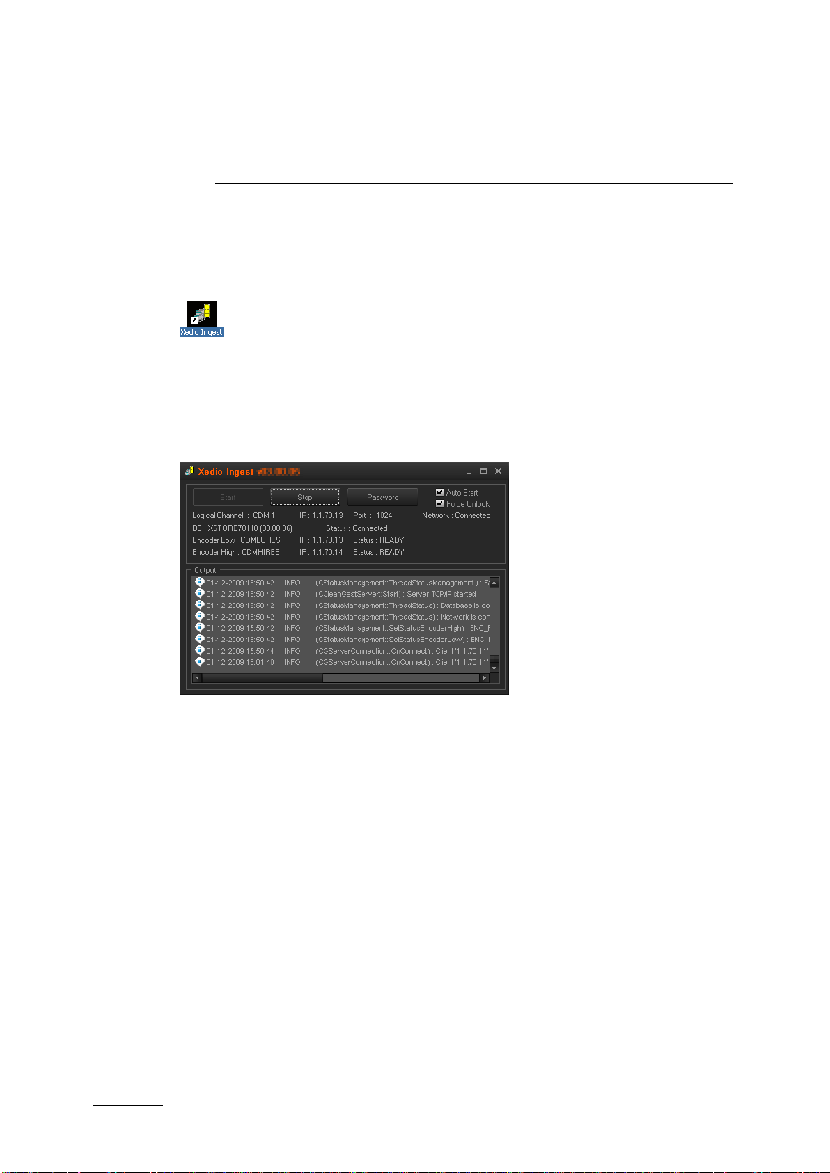
2. Xedio Ingest - Server
The Xedio Ingest (server) application running on a hardwa re encoder is usually set
up to auto start when the computer is switched on. If however it is not set up in
this way the program can be started manually. Click on the Xedio Ingest icon on
the desktop to start the a pplication.
A dialogue box will then appear and ask the user to start the application. At this
point a password can be set up and ticking the check box can set the auto start
option.
When the application is started the message window shows the progress of the
connection to the Client application and displays any problems it may have in the
set up.
Page 9

Xedio Suite Vers i o n 4.2 - User Manual – Ingest Organizer
EVS Broadcast Equipment – June 2012
Issue 4.2.B
3
3. Xedio Ingest
Organizer - Client
3.1 USER INT ERFACE
3.1.1 OPENING INGEST ORGANIZER
To start the Xedio Ingest Organizer application, click on the Xedio
Ingest Organizer icon on the desktop.
This will display a login screen where you need to enter your username
and password.
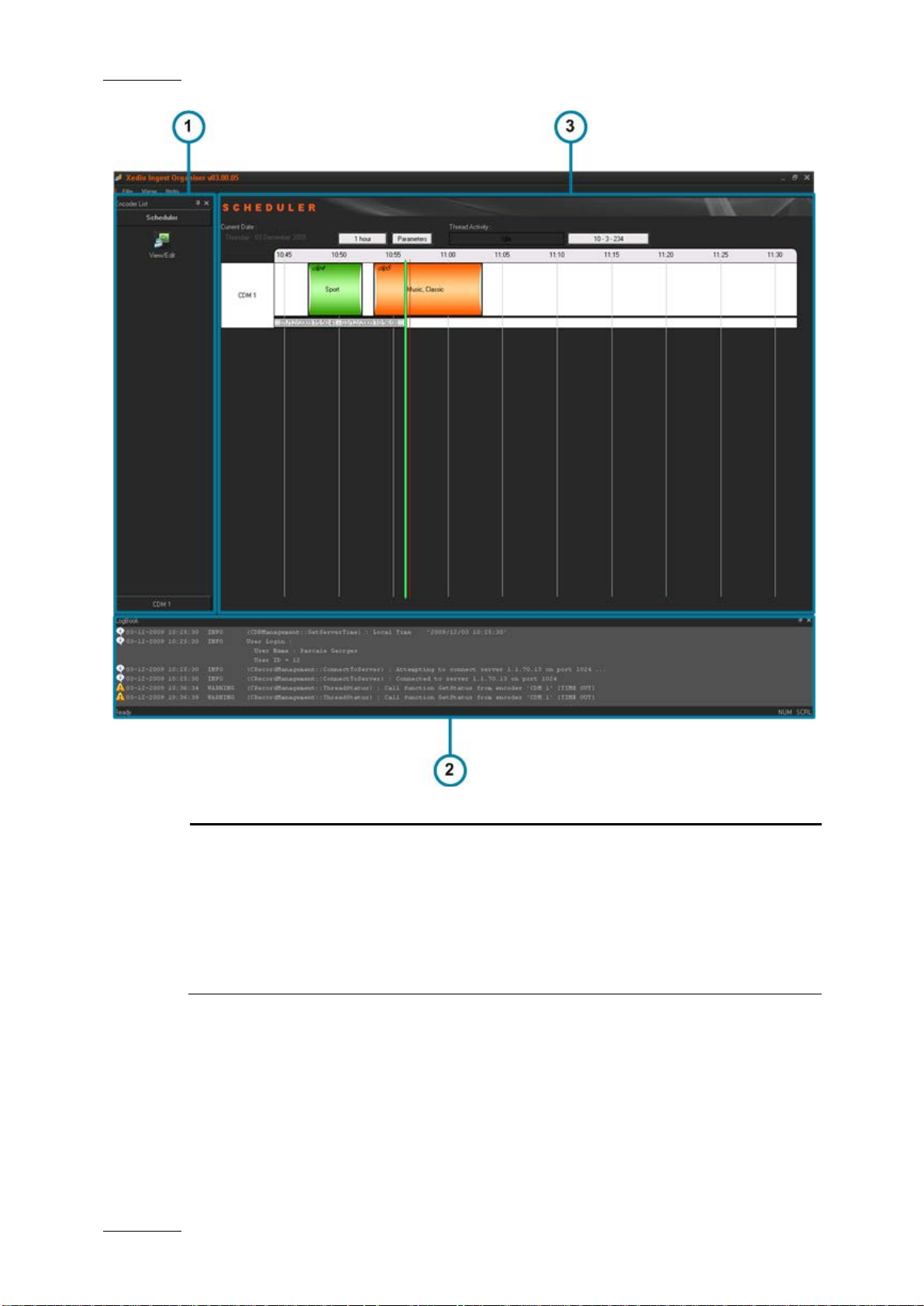
3.1.2 OVERVIEW OF THE XEDIO INGEST ORGANIZER WINDOW
The Xedio Ingest Organizer graphical interface consists of several areas
highlighted on the fo llowing screenshot and shor tly described in the ta ble below.
Note
The color of some user interface elements may vary with the Xedio skin
installed.
Page 10
Issue 4.2.B
Xedio Suite Versi o n 4.2 – User Manual - Ingest Organizer
EVS Broadcast Equipment – June 2012
4
Each tab provides access to a series of items. Once a
items are shown as
Area Description
1. Outlook Area This displays the list of the devices which can be controlled
by the Ingest Organize r.
The Outlook bar presents at least as many tabs as there are
devices to control.
category tab is selected, its specific
icons.
Page 11

Xedio Suite Vers i o n 4.2 - User Manual – Ingest Organizer
EVS Broadcast Equipment – June 2012
Issue 4.2.B
5
that are
This lists the processes undertaken by the software and
Area Description
Select any of these icons to display its relevant interface in
the Work area.
The set up of encoders and VTR devices is made in the
Xedio Manager application.
2. Work Area The Work area displays a timeline with the ingests
scheduled or took place over a period of time for each of the
controlled devices.
It interactively changes when an item is selected in one
category from the Outlook area.
3. Logbook
reports any error enco untered during the processe s.
Page 12
Issue 4.2.B
Xedio Suite Versi o n 4.2 – User Manual - Ingest Organizer
EVS Broadcast Equipment – June 2012
6
3.2 ENCODER DEVICES
3.2.1 OVERVIEW OF THE ENCODERS TAB
Several items are avai lable in the ‘Encoders’ category. They are detailed below.
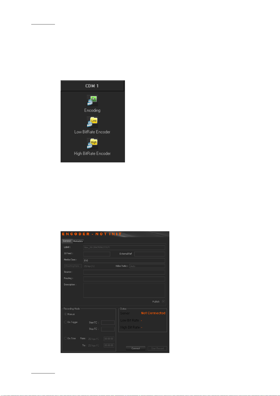
3.2.2 ENCODING
PURPOSE
When you click the Encoding button for an encoder device, the following Encoder
window is displayed in the Work area, allowing you to enter data for the encoded
file, to select the method of recording that will be used and to start the recording
process.
Page 13

Xedio Suite Vers i o n 4.2 - User Manual – Ingest Organizer
EVS Broadcast Equipment – June 2012
Issue 4.2.B
7
res encoding profile is HD, the only option
res encoding profile is SD, the options
t is
Free text to describe how the feed was routed to the
see the encoded media in the client
GENERAL TAB
To create an output file, enter the relevant data into the fields displayed in the
General tab:
Field Description
Label Name you give to the f ile that will be encoded
Id Feed Identification given to a feed that could be provided by a
press agency
External Ref Reference which can help to identify the encoded media,
such as a barcode from a VTR tape.
Media Class Class categorizing the media. The classes are defined in
the Class Manager of t he Xedio Manager applicati on.
Shooting Date Date on which the media has been filmed. To update the
date, click the Shooting Date button and select a date in
the calendar displayed from the drop-down arrow.
Video Ratio Video ratio of the encoded media.
Possible values:
• if the hi-
available in the Video Ratio field is Forced 16:9. This
will obviously be the default value in HD.
• if the hi-
available in the Video Ratio field are Auto (i
automatically detected by the encoder and passed to
Ingest Organizer), Force d 4:3, Forced 16:9.
The default value in SD will be the last one used, per
channel per user.
Source Original source of the feed.
Routing
system.
Description Optional text to desc ribe the encoded media.
Publish Allows to
workstations database lis ts.
METADATA TAB
In the Metadata tab, the users can select one of the available met adata profiles by
clicking in the Metadata Profile field. Then, they can enter metadata values for
the encoded media.
Page 14

Issue 4.2.B
Xedio Suite Versi o n 4.2 – User Manual - Ingest Organizer
EVS Broadcast Equipment – June 2012
8
RECORDING MODE AREA
The recording on an encoder from Xedio I ngest Organizer can be started in one of
the three following modes:
• Manual: when you click the Start Record button, a dialog box allows you to
enter a record duration. The encoding process starts as soon as you click the
Start with Limits button.
• On Trigger: you can enter a start timecode and a stop timec ode. The encoding
process will start and stop at the specified ti mecodes.
• On Time: you can enter start and stop times and dates for the encoding
process. This option i s dimmed when the schedule r interface is available.
STATUS AREA
The Server status shows if the Xedio Ingest Or ganizer application is connected by
IP to the corresponding X edio Ingest Server.
The High and Low Bit rate status show if Xedio Ingest Organizer is
communicating with the encoder software for the specified encoder. Ready is
displayed when the encoder is ready for the recording. During the recording
process, Rec is displa yed.
The Connect button allo ws the user to make the connection manually if th e status
currently shows a disconnection.
Page 15

Xedio Suite Vers i o n 4.2 - User Manual – Ingest Organizer
EVS Broadcast Equipment – June 2012
Issue 4.2.B
9
The Start Record button become s ac tive to start the encoding pr ocess as soon as
the status shows a connected state.
3.2.3 ENCODER
Depending on the encoder type, a Low BitRate Encoder button and/or a High
BitRate Encoder button are av ailable.
When you click one of the Encoder buttons for an encoder device, the following
Encoder window is displayed in the Work area, showing information about the
encoder and a monitori ng output of the current en coding file.
Note
The video shown will o nly be at a rate
• defined by the GOP structure with the CDM[1] encoders (MPEG2 I
frames only will be di splayed: about 2 per second) and
• defin ed by the setup of the s ystem with the CDM[2] encoders.
With the CDM[2], only one monitoring at a time can be performed by a
user.
Page 16

Issue 4.2.B
Xedio Suite Versi o n 4.2 – User Manual - Ingest Organizer
EVS Broadcast Equipment – June 2012
10
3.3 VTR DEVICE
3.3.1 PURPOSE
When you click the Control VTR button from the VTR category tab, the following
VTR window is displayed in the Work area, allowing you to define data for the
recorded file, to contr ol the VTR and mark areas o f the tape to be ingested.
Page 17
Xedio Suite Vers i o n 4.2 - User Manual – Ingest Organizer
EVS Broadcast Equipment – June 2012
Issue 4.2.B
11
3.3.2 GENERAL TAB AND METADATA TAB
These areas have the same fields as the encoder control window. Please refer to
sections ‘General Tab’ on page 7 and ‘Metadata Tab’ on page 7 for a description
of those areas.
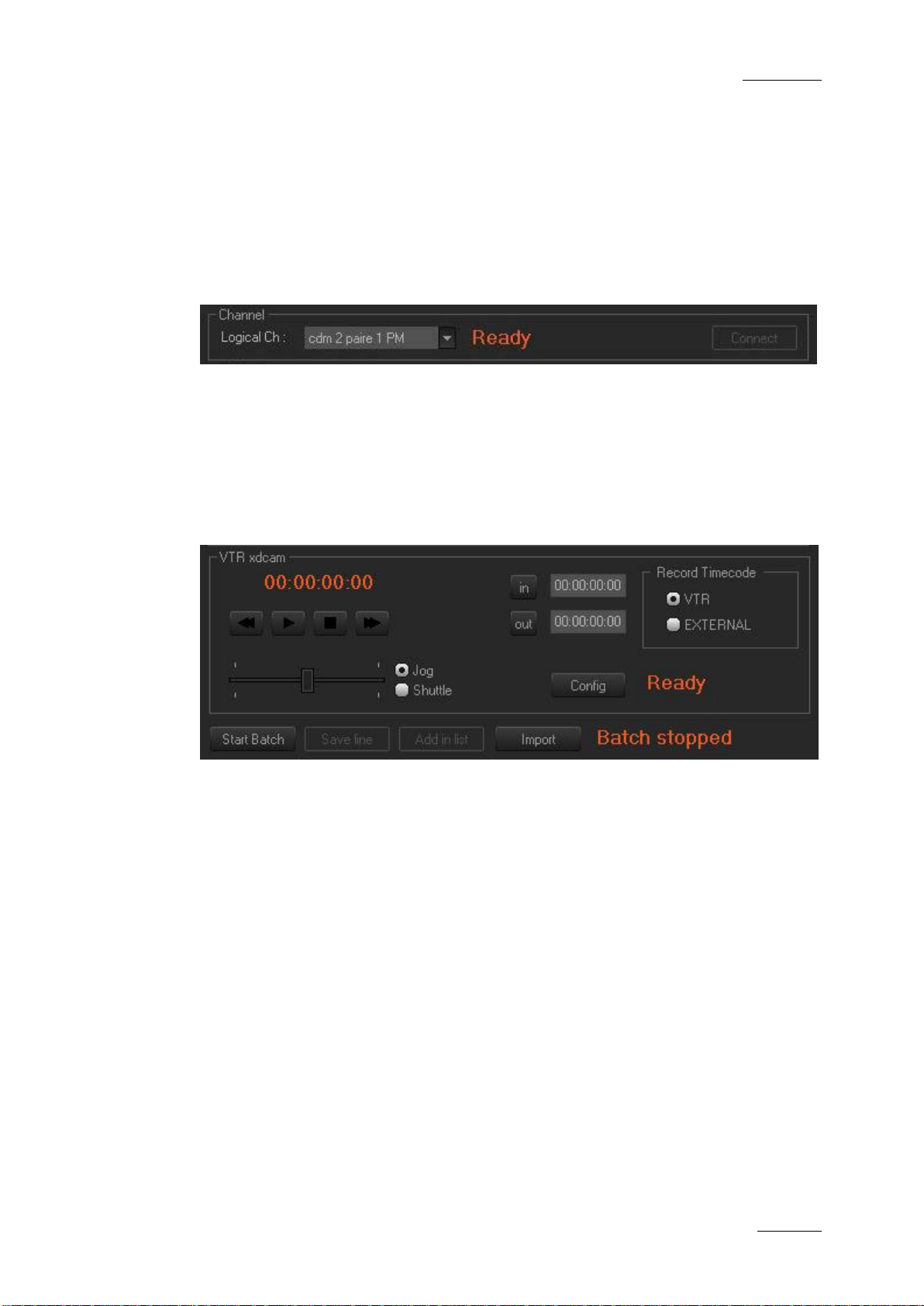
3.3.3 CHANNEL AREA
This parameter allows the user to connect to the logical channel that has been
assigned to ingest the media from the tape in the VTR. Choose the channel and
click the Connect button to establi sh the communication.
3.3.4 VTR AREA
The VTR area provides transport buttons to control the VTR as well as In and Out
buttons to mark sectio ns of the tape to ingest.
The Record Timecode area allows the user to choose between the existing
timecode on the tape or t he external source of timecode connected to th e encoder
when the encoding is p erformed.
Each area of tape can be determined and added to a list using the Add In List
button. When the selection from the tape is complete, the ingest is started by
clicking the Start Batch button.
Page 18

Issue 4.2.B
Xedio Suite Versi o n 4.2 – User Manual - Ingest Organizer
EVS Broadcast Equipment – June 2012
12
3.4 SCHEDULER
3.4.1 PURPOSE
The Scheduler tab displays a timeline with all the records already encoded, being
encoded or scheduled t o take place within the dis played time window.
Each logical encoder h as its own timeline.
The green line is the nowline and reflects the current time. The thin red line
corresponds to the time before which no action can be performed through the
scheduler. Ingest medi a is displayed in the form of blocks in the timeli ne.
3.4.2 TIMELINE VIEW SETTINGS
TIME SPAN
Clicking the [Time] bu tton displays a contextual m enu:
This setting sets the range of time displayed on the timeline. The mouse scroll
button may also be used to change this range and zoom in or out the displayed
range.
Page 19

Xedio Suite Vers i o n 4.2 - User Manual – Ingest Organizer
EVS Broadcast Equipment – June 2012
Issue 4.2.B
13
displayed in such a way that the nowline is always
PARAMETERS
Clicking the Parameters button displays a contextual menu with the following
options:
Menu Items Meaning
Setup Gives options for the amount of encoders displayed on
screen and the adjustm ent of the display refresh rates
Goto Now Returns to the current date and time.
Nowline Focus If this option is selected, the timeline for all encoders is
centered and only the range of the displayed period can
be adjusted. If the option is not selected, the display can
be set to show any tim e period at any date.
Block List Dialog Displays the list of blocks present in the timeline for a
specific period of ti me:
Page 20

Issue 4.2.B
Xedio Suite Versi o n 4.2 – User Manual - Ingest Organizer
EVS Broadcast Equipment – June 2012
14
Menu Items Meaning
Clip Display Settings Allows to select the information to be displayed in the
encoded block :
Show Thumbnails Shows a thumbnail for th e enco ding block.
Refresh Refreshes the graphical interfac e.
About Gives information abou t the version of Ingest Scheduler.
CURRENT DATE
The Current Date field allows to select the date for the timeline display. This is
only available if the Nowline Focus parameter is disabled from the Parameters
menu.
3.4.3 TIMELINE CONTENT
BLOCK STATUS COLORS
The block status is sh own by means of different colors as follows:
Block Color Status
A blue block to the right of the nowline is a Scheduled
ingest.
A currently Recording ingest is orange.
Page 21

Xedio Suite Vers i o n 4.2 - User Manual – Ingest Organizer
EVS Broadcast Equipment – June 2012
Issue 4.2.B
15
Opens an Edit Mode window allowing you to enter
and the
options. Selecting one option opens the
Block Color Status
A green block to the left of the nowline is a s uccessfully
Recorded ingest.
BLOCK CONTEXTUAL MENU
A contextual menu is a vailable when you right-click in the timeline:
Menu Item Description
New Records
parameters for a new f ile to encode.
Modify Records Available when right-c licking on a block.
Opens an Edit Mode window allowing you to update the
parameters of the enco ding file.
View records Opens a View Mode window showing you the parameters
of the encoding file.
Play Provides a sub-menu with the Lowbitrate
Highbitrate
CleanEdit Player window from which you can view the
encoded/encoding block .
BLOCK TOOLTIP
Some of the metadata associat ed to an ingest can be easily viewed by pl acing the
pointer over the corre sponding block. A toolti p is displayed:
Page 22

Issue 4.2.B
Xedio Suite Versi o n 4.2 – User Manual - Ingest Organizer
EVS Broadcast Equipment – June 2012
16
3.5 RECORDIN G TC VERSUS MEDIA TC
The Xedio Ingest server usually pilots two encoders: one i n hi-res (EncHi) and one
in lo-res (EncLow).
Each encoder creates o ne Media file: hi-res medi a file and lo-res media fi le.
Xedio Ingest sends the recording command to both encoders at the same time.
However, according to several parameters, such as the codec, the recording does
not start at the same time on both encoders . So, the TC IN and TC OUT of the two
Media files will differ . This is absolutely normal and ther e can be up to 10 seconds
between both TC IN or between both TC OUT in some cases.
Once the recording is finished, the Xedio Ingest analyses the TC IN and the TC
OUT of each Media file and creates a single Media file corresponding to the
material common to both lo-res and hi-res files.
• The Media TC IN will be the highest value between both TC IN.
• The Media TC OUT will b e the lowest value betwe en both TC OUT.
This difference can be viewed in a player when T C Intra is displayed.
The recording existed from when the first encoder started until the last encoder
stopped. So, in the sched uler:
• The Recording TC IN val ue will be the lowest between b oth TC IN.
• The Media TC OUT value will be the highest between both TC OUT.
In summary, the duration of one recording is always greater than the duration of
the corresponding Media and its Media files. The duration of one Media is always
smaller that the dura tion of its Media files and the corresponding recording.
Additionally, a clip can be created from a media. It will therefore always have its
TC IN and TC OUT within the Media TC IN and TC OUT limits.
This is explained in the followi ng diagram.
Page 23

Xedio Suite Vers i o n 4.2 - User Manual – Ingest Organizer
EVS Broadcast Equipment – June 2012
Issue 4.2.B
17
Page 24

Corporate
+32 4 361 7000
North & Latin America
+1 973 575 7811
To learn more about EVS go to www.evs.com
EVS Headquarters
Liège Science Park
Asia & Pacific
+852 2914 2501
16, rue Bois St Jean
B-4102 Seraing
Belgium
EVS Broadcast Equipment is continuously adapting and improving its products in accordance with the ever changing
requirements of the Broadcast Industry.
The data contained herein is therefore subject to change without prior notice. Companies and product names are
trademarks or registered trademarks of their respective companies.
Other regional offices
www.evs.com/contact
 Loading...