

Page 1

Operating Manual
Version 10.04 - January 2011
Live Slow Motion & Super Slow Motion
Instant Replay & Highlights Production
Page 2

Page 3

EVS Mult icam Version 10.04 – Operating Manual
EVS Broadcast Equipment SA – January 2011
Issue
10.04.A
I
Copyright
EVS Broadc ast Equipment – Copyrig ht © 2002-2011. All rig hts reserved.
Disclaimer
The information in this manual is furnished for informational use only and subject
to change without notice. While every effort has been made to ensure that the
information contained in this user manual is accurate, up-to-date and reliable,
EVS Broadcast Equipment cannot be held responsible for inaccuracies or errors
that may appear in this publication.
Imp rovemen t Reques ts
Your comments will help us improve the quality of the user documentation. Do not
hesitate to send improvement requests, or report any error or inaccuracy on this
user manual by e-mail to doc@evs.tv.
REGIONAL CONTACTS
The address and phone number of the EVS headquarters are usually mentioned in
the Help > About menu in the user interface.
You will find the full list of addresses and phone numbers of local offices at the
following page on the EVS website:
http://www.evs.tv/contacts
USER MANUALS ON EVS WEBSITE
The latest version of the user manual, if any, and other user manuals on EVS
products can be found on the EVS download center, on the following webpage:
http://www.evs.tv/downloadcenter
Page 4

Issue
10.04.A
EVS Multicam Vers ion 10.04 – Operatin g M anual
II
EVS Broadcast Equipment SA – January 2011
Table of Contents
TABLE OF CONTENTS .................................................................................................. II
WHAT’S NEW? ............................................................................................................... 1
OVERVIEW...................................................................................................................... 2
1. INITIAL CONFIGURATION..................................................................................... 3
1.1 APPLICATION SELEC T I O N .................................................................................................... 3
1.2 CONFIGURATION ON LSM REMOTE .................................................................................... 4
2. REMOTE CONTROLLER ....................................................................................... 5
2.1 GENERAL LAYOUT ................................................................................................................ 5
2.2 LED COLOURS ...................................................................................................................... 8
2.3 F-KEYS & SMALL BUTTONS .................................................................................................. 9
2.4 SOFT KEYS............................................................................................................................ 9
2.5 TRANSPORT CONTROLS .................................................................................................... 10
2.5.1 JOG DIAL ................................................................................................................... 10
2.5.2 LEVER........................................................................................................................ 10
3. MAIN MENU ..........................................................................................................11
4. REMOTE PANEL OPERATIONS ..........................................................................14
4.1 OPERATIONS ...................................................................................................................... 14
4.1.1 RECORD .................................................................................................................... 14
4.1.2 MARK ......................................................................................................................... 14
4.1.3 LAST CUE .................................................................................................................. 14
4.1.4 PLAY .......................................................................................................................... 14
4.1.5 IN ............................................................................................................................... 15
4.1.6 OUT............................................................................................................................ 15
4.1.7 JOG KNOB ................................................................................................................. 15
4.1.8 FAST JOG .................................................................................................................. 16
4.1.9 LEVER........................................................................................................................ 16
4.1.10 PLST .......................................................................................................................... 16
4.1.11 BROWSE .................................................................................................................... 16
4.1.12 INSERT ...................................................................................................................... 17
4.1.13 ENTER ....................................................................................................................... 17
4.1.14 MENU ......................................................................................................................... 17
4.1.15 CLEAR ....................................................................................................................... 17
4.1.16 NETWORK ................................................................................................................. 17
4.1.17 GOTO TC ................................................................................................................... 17
4.1.18 GOTO IN / GOTO OU T ............................................................................................... 19
4.1.19 LOOP ......................................................................................................................... 19
4.1.20 RETURN..................................................................................................................... 19
4.1.21 PAGE ......................................................................................................................... 19
4.1.22 Rebooting the Syste m fro m th e LSM Remo te ............................................................... 20
4.2 SELECTION OF CLIP BANKS AND PLAYLISTS ................................................................... 21
4.3 CLIP NUMBERING HIERARCHY .......................................................................................... 22
Page 5

EVS Mult icam Version 10.04 – Operating Manual
EVS Broadcast Equipment SA – January 2011
Issue
10.04.A
III
5. CONTROL MODE ..................................................................................................23
5.1 LIVE (E2E) MODE ................................................................................................................ 23
5.2 SEARCH M ODE ................................................................................................................... 23
5.3 PLAYBACK MODE ............................................................................................................... 23
5.4 SYNCHRONISATION MODE (SWI TCH TO IN)...................................................................... 24
5.5 DEFINITION OF CONTROLLED AND PRIMARY CHANNELS ............................................... 25
5.5.1 Controlled Channel...................................................................................................... 25
5.5.2 Primary Channel ......................................................................................................... 25
5.6 PREFERENCE MODE (PREF) .............................................................................................. 25
5.7 SECONDARY CONTROLLER ............................................................................................... 26
5.7.1 Introduction ................................................................................................................. 26
5.7.2 Interactions Between IPDP and Multic am ..................................................................... 26
6. PGM-PRV MODE ...................................................................................................27
6.1 1PGM+PRV (PRESS A F R OM MAIN MENU) ........................................................................ 27
6.1.1 Secondary Menu ......................................................................................................... 27
6.1.2 Operational Menu ........................................................................................................ 29
6.2 FULL CONTROL AND LEVER CONTROL ............................................................................. 31
7. MULTI PGM MODE ...............................................................................................32
7.1 1/2/3 PGM MOD ES (PR E SS A OR B FROM MAIN MENU) .................................................... 32
7.1.1 Secondary Menu ......................................................................................................... 32
7.1.2 Operational Menu ........................................................................................................ 33
8. VIDEO DELAY .......................................................................................................36
9. CLIP MANAGEMENT ............................................................................................38
9.1 INTRODUCTION................................................................................................................... 38
9.1.1 Clip Struct ure .............................................................................................................. 38
9.1.2 Clip Availability on D is ks .............................................................................................. 39
9.2 USING THE EVS REMOTE PANEL....................................................................................... 39
9.2.1 How to Create a C lip ................................................................................................... 39
9.2.2 Storing a Clip .............................................................................................................. 40
9.2.3 Recalling a Clip ........................................................................................................... 41
9.2.4 Playing Back a C lip ..................................................................................................... 42
9.2.5 Recall and Playbac k of Grow ing C lips .......................................................................... 42
9.2.6 Clearing Clips.............................................................................................................. 43
9.2.7 Copying or Mov ing C lips .............................................................................................. 44
9.2.8 Secondary Menu in Cli p M ode ..................................................................................... 46
9.2.9 How to Searc h for Clips by Tim ec ode .......................................................................... 50
9.2.10 How to Short en a Clip.................................................................................................. 51
9.2.11 Restriping t he T im ec ode of a Clip ................................................................................ 52
In CLIP mode, the timecode of all camera angles of the clip will be changed. ............... 52
9.2.12 8. ................................................................................................................................ 52
9.2.13 Press ENTER to confirm or MENU to cancel. ............................................................... 52
9.2.14 How to Sav e all Clips/ Play lists ..................................................................................... 53
9.3 USING THE CLIP SCREEN .................................................................................................. 53
9.3.1 Clip screen – Standard View ........................................................................................ 53
9.3.2 The Title Bar ............................................................................................................... 54
9.3.3 The Funct ion Bar......................................................................................................... 54
Page 6

Issue
10.04.A
EVS Multicam Vers ion 10.04 – Operatin g M anual
IV
EVS Broadcast Equipment SA – January 2011
9.3.4 The Clip Inf orm at ion Area ............................................................................................ 57
9.3.5 The Clip Managem ent Area ......................................................................................... 58
9.3.6 Selecting a Clip w it h Tablet and St y lus ......................................................................... 59
9.3.7 Selecting a Clip w it h the Keyboard ............................................................................... 59
9.3.8 How to Name a Clip .................................................................................................... 60
9.3.9 How to Change the Prim ary C am era of a Clip .............................................................. 60
9.3.10 Recalling a Clip ........................................................................................................... 61
9.3.11 How to Cancel a N etwork C opy on the VGA ................................................................. 61
9.3.12 How to Rest ripe t he Timec ode of the Current C lip ........................................................ 62
9.3.13 Moving and Copy ing C lips ........................................................................................... 63
9.3.14 Clip Screen – Ex t ended View ....................................................................................... 65
9.4 USING THE VDR PANEL ...................................................................................................... 66
9.4.1 VDR Panel – Lower Sec tion ........................................................................................ 66
9.4.2 VDR Panel – U pper Section ........................................................................................ 66
9.4.3 VDR Panel – Player W indow ....................................................................................... 67
9.4.4 VDR Panel – Recorder WINDOW ................................................................................ 70
10. KEYWORD MANAGEMENT ..................................................................................72
10.1 CREATING AND SELECTING THE KEY WO RD FIL E ............................................................ 72
10.1.1 Creating the Key w ord F ile F rom a PC .......................................................................... 73
10.1.2 Selecting the C urrent Key w ord F ile .............................................................................. 74
10.1.3 Editing the Keywor d F ile f rom the Mult ic am Applicat ion ................................................ 74
10.2 ASSIGNING KEYW OR D S USING THE VGA SCREEN .......................................................... 76
10.2.1 Keyword Window s ....................................................................................................... 76
10.2.2 How t o Assign a Key w ord t o a Clip .............................................................................. 77
10.2.3 How to Clear a Keyw ord w it h the Keyboard .................................................................. 77
10.2.4 How to Clear a Keyw ord w it h the Sty lus ....................................................................... 77
10.2.5 How to Edit the R ank ing of the C urrent Clip Wit h the Keyboard .................................... 77
10.2.6 How to Edit the R ank ing of the C urrent Clip With the Stylus .......................................... 77
10.2.7 How to Clear All Keyw ords and t he R ank ing of a Clip ................................................... 78
10.2.8 How to Name a C lip Using t he Keywords : .................................................................... 78
10.3 SEARCHING THE DATABASE USING THE VGA SCREEN................................................... 78
10.3.1 Search Window ........................................................................................................... 78
10.3.2 Search Criteria and Searc h Opt ions ............................................................................. 79
10.3.3 Clearing Keywords in t he Searc h C rit eria ..................................................................... 81
10.3.4 Search Result s ............................................................................................................ 82
10.4 ASSIGNING KEYW OR D S USING THE REMOTE PANEL...................................................... 84
10.4.1 Keyword Sett ings ........................................................................................................ 84
10.4.2 Assigning Keyw ords in Lis t Mode ................................................................................. 84
10.4.3 Assigning Keyw ords in N um eric M ode ......................................................................... 86
10.5 SEARCHING THE DATABASE USING THE REMOTE PANEL .............................................. 86
11. PLAYLIST MANAGEMENT ...................................................................................89
11.1 GENERAL INFORMATION.................................................................................................... 89
11.2 PLAYLIST MODES ON T HE REMOTE PANEL ...................................................................... 90
11.2.1 Introduction ................................................................................................................. 90
11.2.2 Access ing t he Play list Edit Mode ................................................................................. 90
11.2.3 Access ing t he Play list Play out Mode ............................................................................ 91
11.3 PLAYLIST DISPLAY ON T H E VGA ....................................................................................... 91
11.3.1 VGA Playlist Bank Sc reen ........................................................................................... 91
Page 7

EVS Mult icam Version 10.04 – Operating Manual
EVS Broadcast Equipment SA – January 2011
Issue
10.04.A
V
11.3.2 VGA Playlist Sc reen .................................................................................................... 92
11.4 ACTIVATING AND LOADING PLAYLISTS............................................................................. 93
11.4.1 Activat ing Vers us Loading a Play lis t ............................................................................. 93
11.4.2 How to Activ at e a Local or Distant Play list .................................................................... 93
11.4.3 How to Recall and Load a Play lis t ................................................................................ 94
11.4.4 How to Exit The Playlist Mode ..................................................................................... 94
11.5 DELETIN G PLAYLIST S ........................................................................................................ 95
11.5.1 How to Delete a Play lis t ............................................................................................... 95
11.5.2 How to Delete All Play lis ts of a Bank ............................................................................ 95
11.6 NAMIN G A PLAYLIST OR AN ELEMENT IN A PLAYLIST...................................................... 96
11.6.1 How to Name a Play lis t From the VGA Play lis t Bank Screen ........................................ 96
11.6.2 How to Name t he Current Play lis t on the VGA Playlis t Sc reen ...................................... 96
11.6.3 How to Name t he Current Elem ent in t he Loaded Play lis t ............................................. 96
11.7 BROWSING WITHIN A PLAYLIST ........................................................................................ 97
11.7.1 Possible Brows ing M et hods ......................................................................................... 97
11.7.2 Browsing Through a Playl is t ........................................................................................ 97
11.7.3 Browsing Quick ly T hrough a Play lis t ............................................................................ 97
11.8 PLAYOUT FUNCTIONS WITH PLAYLISTS ........................................................................... 98
11.8.1 Rolling a Playlist .......................................................................................................... 98
11.8.2 Functions Av ailable f rom the VGA Playlis t Sc reen ........................................................ 98
11.8.3 Functions Av ailable on t he R em ot e in Playlist Play out Mode......................................... 99
11.9 OVERVIEW OF EDITING FUNCTIONS IN PLA Y L IST EDIT MODE ...................................... 100
11.9.1 Main Menu in Playlis t Edit Mode ................................................................................ 100
11.9.2 Secondary Menu in Playli s t Edit M ode ....................................................................... 101
11.10 ADDING & REPLACING CLI PS IN A PLAYLI ST .................................................................. 103
11.10.1 Possible Met hods f or Adding C lips ............................................................................. 103
11.10.2 Modifying a D istant Play lis t ........................................................................................ 103
11.10.3 How to Quic k ly Add Clips to the Current Play lis t ......................................................... 103
11.10.4 How to Insert Clips into a Playlist ............................................................................... 104
11.10.5 How to Insert the Res ult of a Clip Search int o a Playlist .............................................. 104
11.10.6 Inserting Grow ing C lips int o Play lists.......................................................................... 105
11.10.7 How to Delete Play lis t Element s f rom a Playlis t .......................................................... 106
11.10.8 How to Move an Elem ent W ithin a Playlis t.................................................................. 106
11.10.9 How to Change the Camera Angle of a Playlist Element ............................................. 107
11.11 COPYIN G PLAYLI ST S ........................................................................................................ 108
11.11.1 Introduction ............................................................................................................... 108
11.11.2 Copy Options ............................................................................................................ 108
11.11.3 Possible Copy Ac t ions ............................................................................................... 109
11.11.4 How to Copy a Playl ist f rom the R em ote Panel........................................................... 109
11.11.5 How to Copy a Playl ist f rom the VGA Cl ip Sc reen ...................................................... 110
11.11.6 Copying Playlists with On-Air Clips ............................................................................ 112
11.12 OTHER EDITING FUNCTIONS FOR PLAYLISTS ................................................................ 112
11.12.1 How to Trim C lips into a Play list ................................................................................. 112
11.12.2 How to Sort the Play lis t Element s by TC IN ................................................................ 113
11.12.3 How to Merge Playlis t s .............................................................................................. 113
11.12.4 Consolidating a Play lis t ............................................................................................. 113
11.12.5 Generating a Continuous T i m ec ode in a Playl is t ......................................................... 114
11.13 THE AUXILIARY AUDIO CLIP ............................................................................................. 115
11.13.1 Introduction ............................................................................................................... 115
11.13.2 How to Add/Rem ove an Auxiliary Audio C lip t o a Playlist ............................................ 116
Page 8

Issue
10.04.A
EVS Multicam Vers ion 10.04 – Operatin g M anual
VI
EVS Broadcast Equipment SA – January 2011
11.14 TRANSITION EFFECTS ..................................................................................................... 116
11.14.1 Description ................................................................................................................ 116
11.14.2 Accessing Commands for T rans it ion Effects............................................................... 117
11.14.3 Default D urat ion f or Video and Audio T rans it ion ......................................................... 117
11.14.4 Overview of Transitions Effect Types ......................................................................... 118
11.14.5 How to Define a T rans it ion Effec t ............................................................................... 119
11.15 SPLIT AUDIO ..................................................................................................................... 120
11.15.1 Introduction ............................................................................................................... 120
11.15.2 Menus in Split Audio Mode ........................................................................................ 120
11.15.3 OSD Display in Split Audio M ode ............................................................................... 121
11.15.4 Default D urat ion f or the Audio and Video Trans it ions .................................................. 122
11.15.5 Associat ions of Audio and Video Transition Types...................................................... 122
11.15.6 Default M ode f or Extending a T ransition..................................................................... 123
11.15.7 Changing the Audio or Video Effec t D uration.............................................................. 126
11.15.8 Performing A ‘V Base’ Edit ......................................................................................... 126
11.15.9 Performing An ‘A Base’ Edit ....................................................................................... 128
11.15.10 How to Insert a Clip into a Playlist W ith Split Audio ..................................................... 131
11.16 SWAP AUDIO TRACKS ...................................................................................................... 132
11.16.1 Introduction ............................................................................................................... 132
11.16.2 How to Enable the Audio Swap Mode ........................................................................ 132
11.16.3 How to Perf orm a Swap Audio T rac k in Auto Mode .................................................... 132
11.16.4 How to Perf orm a Swap Audio T rac k in Manual Mode ................................................ 135
11.16.5 Deleting Swap Point s ................................................................................................ 135
11.16.6 Navigating Am ong Sw ap Point s ................................................................................. 136
11.17 REPLACE FUNCTION ........................................................................................................ 136
11.17.1 Introduction ............................................................................................................... 136
11.17.2 Entering the Replac e F unc t ion ................................................................................... 136
11.17.3 Replace Edit and R eplac e Play bac k M odes ............................................................... 136
11.17.4 Replace wit h IN/ OU T Points or with IN Point Only ...................................................... 137
11.17.5 How to Perf orm a Replac e ......................................................................................... 137
11.17.6 Loop Mode in the Replace F unc tion ........................................................................... 139
12. TIMELINE MANAGEMENT..................................................................................140
12.1 INTRODUCTION................................................................................................................. 140
12.1.1 Timeline Creat ion ...................................................................................................... 140
12.1.2 Timeline Editing......................................................................................................... 140
12.1.3 Timeline Playout ........................................................................................................ 141
12.1.4 Principles for Ac c es s ing Timelines ............................................................................. 141
12.2 CREATING TIME L INE S ...................................................................................................... 142
12.2.1 How to Create a T im eline F rom a playlis t From the Rem ot e Panel .............................. 142
12.2.2 How to Create a T im eline F rom a playlis t From the VGA ............................................ 142
12.3 COPYING TIMELINES ........................................................................................................ 143
12.3.1 Overview................................................................................................................... 143
12.4 TIMELINE EDIT MODE ....................................................................................................... 143
12.4.1 Access ing t he Timeline Edit M ode ............................................................................. 143
12.4.2 Controlling the R ec order ............................................................................................ 144
12.4.3 OSD Display ............................................................................................................. 144
12.4.4 LCD Information ........................................................................................................ 144
12.5 TIMELINE PLAYOUT MODE ............................................................................................... 145
12.5.1 Access ing t he Timeline Play out M ode ........................................................................ 145
Page 9

EVS Mult icam Version 10.04 – Operating Manual
EVS Broadcast Equipment SA – January 2011
Issue
10.04.A
VII
12.5.2 OSD Display ............................................................................................................. 145
12.5.3 LCD Display .............................................................................................................. 145
12.6 EDITING OPERATIONS ..................................................................................................... 146
12.6.1 Extend Overw rit e....................................................................................................... 146
12.6.2 Insert Overwrite ......................................................................................................... 148
12.6.3 How to Add a Clip to a Timeline ................................................................................. 149
13. OPERATING ON XNET NETWORK ....................................................................150
13.1 INTRODUCTION................................................................................................................. 150
13.2 DISCONNECTING FROM XNET ......................................................................................... 150
13.3 SELECTIN G A SERVER O N XN ET ..................................................................................... 150
13.4 OPERATIONS .................................................................................................................... 152
13.4.1 How to Recall/Play Back a Remote Clip ..................................................................... 152
13.4.2 How to Name a Remote Clip...................................................................................... 153
13.4.3 How to Modify IN/Out Points of a Remote Clip............................................................ 153
13.4.4 How to Insert Remote Clips Into a Playlist .................................................................. 154
13.4.5 How to Roll a Playlist With Remote Clips ................................................................... 154
13.4.6 How to Create Loc al C lips With R emote R ec ord Trains .............................................. 155
13.5 WORKING WITH MA P P E D NETWORK CAMERAS ............................................................. 156
14. PAINT MODE .......................................................................................................157
14.1 INTRODUCTION................................................................................................................. 157
14.2 PAINT MODE MONITOR DISPLAY ..................................................................................... 158
14.3 FUNCTION DE S CRIP TION ................................................................................................. 159
15. TARGET MODE ...................................................................................................162
15.1 INTRODUCTION................................................................................................................. 162
15.2 CREATING A TA RG E T TRA CK .......................................................................................... 163
15.2.1 Selecting the t y pe of trac k ing objec t ........................................................................... 163
15.2.2 Selecting Other Paramet ers of the Tracking Object .................................................... 163
15.2.3 How to Highlight Video M at erial ................................................................................. 164
15.2.4 Rules When U s ing Key f ram es ................................................................................... 164
15.3 TARGET MODE MONITOR DISPLAY ................................................................................. 165
16. OFFSIDE LINE MODE .........................................................................................168
16.1 INTRODUCTION................................................................................................................. 168
16.1.1 Definition and Lic ens e C ode ...................................................................................... 168
16.1.2 Activat ing t he Offs ide Line M ode................................................................................ 168
16.1.3 Access ing t he Offs ide Line M ode ............................................................................... 168
16.1.4 Overview on t he Of fside Line C om m ands................................................................... 169
16.2 HOW TO MARK AN OFFSIDE LINE .................................................................................... 170
16.3 HOW TO EDIT AN OFFSIDE LINE ...................................................................................... 171
16.4 HOW TO PLAY THE OFFSIDE SEQUENCE ....................................................................... 171
16.5 CUE POINTS RELATED TO OFFSIDE SEQUENCE............................................................ 172
17. SPLIT SCREEN MODE .......................................................................................173
17.1.1 Vertical Split .............................................................................................................. 173
17.1.2 Horizontal Split .......................................................................................................... 175
17.1.3 Split MIX ................................................................................................................... 176
17.1.4 Auto-track ing m ode ................................................................................................... 176
Page 10

Issue
10.04.A
EVS Multicam Vers ion 10.04 – Operatin g M anual
VIII
EVS Broadcast Equipment SA – January 2011
18. HYPERMOTION MODE .......................................................................................177
18.1 INTRODUCTION................................................................................................................. 177
18.1.1 Definition and Lic ens e C ode ...................................................................................... 177
18.1.2 Activat ing t he Hyperm ot ion M ode .............................................................................. 177
18.1.3 Access ing and Leaving t he H ypermotion Mode .......................................................... 177
18.2 OVERVIEW ON COMMANDS ............................................................................................. 178
18.2.1 Main Menu ................................................................................................................ 178
18.2.2 Secondary Menu ....................................................................................................... 178
18.2.3 Key Comm ands......................................................................................................... 179
18.3 CONTROLLING THE HYPERMOTIO N CAMERA FRO M THE REMOTE .............................. 181
18.3.1 Defining the N um ber of Memory Bloc ks ..................................................................... 181
18.3.2 Color Code for M em ory Block St at us ......................................................................... 182
18.3.3 General Process wi t h Single-Bloc k M em ory ............................................................... 183
18.3.4 General Process wi t h M ult iple-Bloc k M em ory ............................................................. 184
18.3.5 Specific Process with Multiple-Memory Bloc k s on Vision Res earc h C am eras .............. 184
18.3.6 Creating a Clip W it h the Mat erial f rom the Hyperm ot ion C am era ................................. 186
18.3.7 Cue Point Creat ion and R ec all ................................................................................... 186
19. SONY, XTEN DD35, ODETICS & VDCP PROTOCOLS .......................................187
19.1 PROTOCOL OVERVI EW .................................................................................................... 187
GLOSSARY ..................................................................................................................189
Page 11

EVS Mult icam Version 10.04 – Operat ing Manual
EVS Broadcast Equipment SA – January 2011
Issue
10.04.A
1
The changes linked to new features on Multicam version 10.04 are listed in the
table below, and are identified in the user manual by the ‘New’ logo in the margin
Updates for Multicam - Version 10.04
What’s New?
Section 18
The Hypermotion chapter has been reviewed and updated
to include:
• the new behavior for the Vision Research cameras,
• other general information (cue point, memory block
display, more information on the key commands, etc.).
Page 12

Issue
10.04.A
EVS Multicam Vers ion 10.04 – Operating Manual
2
EVS Broadcast Equipment SA – January 2011
Overview
The aim of this manual is to familiarize the operator with the Multicam software for
EVS High Definition and Standard Definition servers, and its Remote Panel, so as
to learn as quickly and efficient ly as poss ible t he bas ic operations.
The CLIP & PLAYLIST MANAGEMENT functions allow the operator to keep up to
5400 clips on a server and of course to replay all or some of them. A playlist
consists of a list of clips (90 playlists can be defined) with video and audio
transitions.
The XNet option networks XNet servers and other machines into a fully integrated
production environment. Any clip, recorded by any server on the network is
available instantly for editing and/or play-out to any ot her operator.
The SPLITS CRE EN (horizontal, vertical or mix) option displays simultaneously two
synchronized actions side by side on the main prog ram output.
The PAINT option (Telestrat or) draws and applies keying on the recorded pictures.
Sport actions can be analyzed using differ ent colored circles, arrows and lines.
The TARGET TRACK option follows a target with a highlighted circle, box or
ellipse, and can zoom in the selec ted portion of the recorded pictures.
The OFFSIDE LINE option allows you to draw the offside line or area on the
screen by shading a portion the pitch.
Page 13

EVS Mult icam Version 10.04 – Operat ing Manual
EVS Broadcast Equipment SA – January 2011
Issue
10.04.A
3
Title bar
Configuration
windows
Task bar
Application
window
Message
window
1. Initial Configuration
1.1 APPLICA TION SELECTION
The EVS software is used for configuration and maintenance operations. It is also
used to select which application configuration to run, since EVS disk recorders
have the ability to run various configurations (LSM 2REC 4PLAY, LSM 3REC
3PLAY, LSM 4 REC 2 PLAY, SLSM, SLSM+1REC, etc.). In the associated AVCFG
module, you can also specify the channel configuration you want to use and
several audio and video parameters.
When turning on the EVS mainframe, the first step is the PC boot sequence, then
the EVS software is started:
• If a default application has been previously selected, this application will start
automatic ally aft er a few seconds if no key is hit.
• If a default application hasn't been defined or if the space bar is hit, the
system will remain in the EVS main menu and wait for the operator's next
command.
You will find complete information about regarding the EVS Menu in the XT Tech
Ref Software manual.
Page 14

Issue
10.04.A
EVS Multicam Vers ion 10.04 – Operating Manual
4
EVS Broadcast Equipment SA – January 2011
1.2 CONFIGURATION ON LSM REMOTE
Before you start using the Multicam application in Multicam LSM mode, you need
to ensure that the parameters are properly defined in the Setup menu of the
Remote Panel, and in the Setup Configurat ion module of the Multicam appli cation.
The new parameters are saved as soon as t hey are modified.
Important
Prior to using Multicam, the operator should enter the Setup menu and
set all necessary parameters. If clips are stored with certain parameters
and the operator wishes to change them afterwards, those clips and
playlists will not change. It is thus important to set these parameters first.
The Multicam Configuration manual includes a detailed description of all settings
which can be defined on the Remote Panel.
Page 15

EVS Mult icam Version 10.04 – Operat ing Manual
EVS Broadcast Equipment SA – January 2011
Issue
10.04.A
5
2. Remote Controller
2.1 GENERAL LAYOUT
The following diagram shows the Remote Panel along with a brief description of
each area.
Page 16

Issue
10.04.A
EVS Multicam Vers ion 10.04 – Operating Manual
6
keys & small
With LCD display, allows the operator to enter the
Used in playlist management to insert clips into a
PGM mode, pressing this button toggles
EVS Broadcast Equipment SA – January 2011
Note
The operational buttons have PRIMARY and SECONDARY functions and
are divided into upper and lower sections. By pressing the SHIFT button
you gain access to the sec ondary functions.
1.
F-
Multi-purpose keys
buttons
2. Soft keys
Multicam MENU system
3. Lever Initiates slow motion and playlist replay
4. Jog dial Used to accurately cue disk recorder
5.
Operational
block 1
PLST Initiates active playlist
LOOP
This option records the main output (PGM1) to the first
input (CAM A) of Multicam.
BROWSE Used to browse through clips, playlis ts, cue points
INSERT
playlist
IN Sets Mark IN at the current position
GOT O IN Goes to t he defined Mark IN
OUT Sets Mark OUT at the current position
GOTO OUT Goes to t he defined M ark O UT
TAKE
In PGM+PRV mod e, pressing this button swaps cameras
on PGM and PRV monitors
In Multi-
between CAM selection and PGM selection modes.
In 2 PGM mode, when both PGMs are selected on the
Remote Panel, pressing this button swaps the content
loaded on PG M1 with the one loaded on PGM2 and vice-
versa.
In Playlist Edit mode, pressing this button inserts the
clip loaded on the PRV channel into current playlist.
LEVER
Changes the lever range to secondary mode (see setup
menu for range selection)
Page 17

EVS Mult icam Version 10.04 – Operat ing Manual
EVS Broadcast Equipment SA – January 2011
Issue
10.04.A
7
Page 18

Issue
10.04.A
EVS Multicam Vers ion 10.04 – Operating Manual
8
EVS Broadcast Equipment SA – January 2011
6.
Operational
Block 2
PLAY Initiates playback
NETWORK
LAST CUE Re-cues EVS server to previous cue point
GOTO TC Allows timecode entry, with «F» keys
FAST JOG
MARK Used to enter re-usable cue point (256 cycling cues).
RECORD Initiates “E2E” mode
RETURN
PRV CTL Enables/d isables the Preview Control mod e.
Enters the XNet menu. (connect to other servers on the
network)
Used with jog dial for rapid, manual re-cue. This mode is
automatic ally reset af ter P LAY/LIVE commands.
Inside a clip, allows the operator to return to the same
picture inside the record train, if it st ill ex ists.
PAGE Selects current clip page, from 1 to 10.
7. LCD Display Provides curr ent status of system
2.2 LED COLOURS
A selected key lights red.
When a key lights green, it means a value in relation with this key exists.
For example: F1 to F0 keys
• Green light means a clip has been stored in relat ion with the key.
• Green flashing light means a clip is being created .
• Red light means t he clip associated to the key is playing or is ready to play.
• Red flashing light means a clip is being d eleted (in network mode)
Page 19

EVS Mult icam Version 10.04 – Operat ing Manual
EVS Broadcast Equipment SA – January 2011
Issue
10.04.A
9
F1 F2 F3 F4 F5 F6 F7 F8 F9 F10
M EN U SHI FT CLEAR EN TER
Stores or recalls clips, recall playlists and enter timecode
MENU
SHI FT
F1
F10
-
CLEAR
ENTER
2.3 F-KEYS & SMALL BUTT ONS
This button provides access to the Secondary Menu. Also used as
CANCEL in some messages when confirmation is required.
Note: SHIFT + MENU returns to Main menu
Enables use of the secondary key functions.
Note: This key remains active even if released, until another key
has been hit.
information.
Is a mult i-purpose key used to clear clips or playlists, and to clear
IN/OUT points.
Is used to append clips at the end of the current playlist, and to
validate other options and messages.
2.4 SOFT KEYS
The soft keys have PRIMARY and SECONDARY functions and are divided into
upper and lower sections.
The LCD display is divided in two menus.
• To access the secondary functions in the operational menu (A’ to D’), press
the SHIFT button.
• To access the secondary menu, press MENU from the remote controller. The
Page 20

Issue
10.04.A
EVS Multicam Vers ion 10.04 – Operating Manual
10
secondar y menu is used to define settings that do not require regular changes,
without having to return to the Setup menu.
• To ret urn t o the operational menu, press the MENU key again.
• To return to the Main menu in M ult icam, press SHIFT + MENU.
2.5 TRANSPORT CONTROLS
2.5.1 JOG DIAL
The JOG DIAL allows the operator to pass into Search mode and thus to
choose exactly the Short OUT or Short IN image. Move the jog dial clockwise to
search forw ard and move it count er-clockwise to searc h backwards. One revolution
of the jog dial will produce a jump of approxim at ely 35 fr ames. This number can be
multiplied by enabling the Fast mode. The multiplication factor is defined in the
Setup menu.
EVS Broadcast Equipment SA – January 2011
Note
The jog dial is also used to do the following:
The jog dial is active at all times when the syst em is in Play & Record modes.
2.5.2 LEVER
The LEVER is used to start a play or to modify slow motion speed. Its run
can be of two d ifferent t ypes regarding the lever mode. In this mode, the lever run
goes from 0 up to 100%.
Different ranges are available to play material from –400% to 400% (see Setup
menu - pag e 6. 1 - F 5 for selection).
To gain access to this second speed range, press SHIFT + LEVER from the remote
controller.
• set parameters in the Setup menu. Refer to the Setup menu section
for more information.
• browse inside the clips database, the cue points or the current
playlist. Refer to the explanation of the BROWSE function for more
details.
Note
When SD SUPER MOTION material is loaded on the primary channel, the
lever range as a larger, flat step at 33%.
With HD SUPER MOTION, the step is at 33% or 50% depending on the
camera.
The lever is also used to adjust speed, effects type and duration in Playlist Edit
mode.
Page 21

EVS Mult icam Version 10.04 – Operat ing Manual
EVS Broadcast Equipment SA – January 2011
Issue
10.04.A
11
2Rec 4Play Server Ver:10.03.xx
Split
Paint
Target
Setup
1PGM+PRV
3 PGM
INTRODUCTION
After the boot sequence of the Multicam system, the LCD screen of the Remote
Control panel will display the Main menu:
F1: 1 Remote F6: Exi t
F2: 2 Remotes F7: Clear all clips
F3: 3 Remotes F8: Stop Record
F4: 4 Remotes F9: Fil l Play lis t
F5: Char. On/Off F0: Save Clips+Plist
3. Main Menu
The Main menu has special function key operations as shown above, as well as
the “soft” keys options to enter 1PGM, 1PGM+PRV, 2PGM, or 3PGM modes (if
available) and to enter the Setup menu to configure your remote controller or to
add special functions to your application.
Note
If 2 channels are available for the 1
PGM. If 3 channels ar e available, the B key will display 3 PGM.
st
Remote, the B key will display 2
HOW TO RETURN TO THE MAIN MENU
From any section of the application, except Playlist mode, press SHIFT + MENU
on the first Remote Control panel to return to the Main menu.
Page 22

Issue
10.04.A
EVS Multicam Vers ion 10.04 – Operating Manual
12
EVS Remote Panels. Depending on the number of play
In this configuration, each Remote Panel can select
screen display (Timecode, Clip
EVS Broadcast Equipment SA – January 2011
FUNCTION KEYS IN THE MAIN MENU
Select the correspond ing Function key (F_ key), and then press ENTER to validate
the selection.
Function Key Use
F1 to F 4
If desired, the Multicam system can be run using 1, 2, 3 or 4
channels available in the current configuration, 1-, 2-, 3- or 4-
Remote modes will be available from the M ain menu.
F1: 1 Remote One Remote Panel is used in the configuration
F2: 2 Remotes Two Rem ot e Panels are used in the configuration.
If 4 play channels are available, when selecting the 2 Remotes
mode, the operator can chose between 2 configurations:
• 2 play channels for each remote:
PGM+PRV or 2PGM mode. Each Remote Panel can manage
video transitions (cut, mix, wipe) in PGM+PRV and playlist
modes.
• 3 pl ay ch annels for the 1
the second remote.
In this configurat ion, the 1
3PGM mode and can manage video transitions. The 2
remote is forced to 1PGM mode and can only handle cut
transitions.
st
remote and 1 play channel f or
st
remot e can select PGM+PRV or
nd
F3: 3 Remotes Thr ee Remote Panels are used in the configuration.
F4: 4 Remotes Four Remote Panels are used in the configuration.
F5: Char . On/O ff
Enables or disables the on-
ID,…) on the output monitors.
F6 : Ex it Exits the Multicam software and returns to the EVS Menu.
F7: Clear all
clips
Clears all clips. All clips will be lost. A confirmation of this
command is required.
For more information to this action, refer to the section 9.2.6
‘Clearing Clips’, on page 43.
Note: This command is not similar to the Clear Video Disks
from the Maintenance menu. If you wish to refresh completely
the server, i.e. to clear all clips including the protected ones,
you need to use Clear Video Disks rather than Cle ar all clips.
F8: Stop Record
Stops the record. The REC key will go off and the F8 function
key is now used to restart the record.
F9 : F ill Pla yli st
«Dump» feature which allows all clips to be «dumped» at the
Page 23

EVS Mult icam Version 10.04 – Operat ing Manual
EVS Broadcast Equipment SA – January 2011
Issue
10.04.A
13
end of the current playlist. This allows the operator to save all
Function Key Use
material to tape, as a backup feature after a show is complete.
You can select in the Set up menu which camera angles h ave to
be included in the Fill Play-List function.
If your clips are currently connected to another server on the
network, the clips from that server will be added to your current
playlist.
Make sure the playlist you have selected is an empty one. This
function will append the clips at the end of an ex isting playlist.
Important
In order to guarantee the validity of data and clips previously saved, it is
advised to properly exit the application by pressing ALT+ Q and ENTER
from the keyboard, or F6 and then ENTER from the Remote Panel. DO
NOT TURN OFF THE SYSTEM WHILE THE APPLICATION IS RUNNI NG.
Page 24

Issue
10.04.A
EVS Multicam Vers ion 10.04 – Operating Manual
14
4.1 OPERATIONS
4.1.1 RECORD
This key lights red when the system is recording. Pressing this key brings the
system in E/E (“live”) mode, and starts the record if necessary (depending on t he
settings of the Setup menu). The E/E mode is actually playing pictures already
recorded by the system, and has a delay of 3 frames compared to the live source,
on all audio and video tracks.
EVS Broadcast Equipment SA – January 2011
4. Remote Panel
Operations
4.1.2 MARK
This function m arks up to 256 cues that can be mar ked while recording or playing.
The cues are marked on the LIVE or PLAYBACK program depending on the value
set in the Setup menu. When the operator has marked 256 cues, the next one will
overwrite the oldest one.
4.1.3 LAST CUE
This function re-cues the EVS server to previous cue point re lative to the current
timecode position. Each time the Last Cue button is pressed, the EVS server recues to the previous cue, etc. When recalling a cue point, the cue num ber appears
in the upper left corner of the OSD if this option is enabled in the Setup menu
(page 1. 1, F4)
4.1.4 PLAY
This function initiates a forward motion. It can also be used to start playback of
playlists and clips (refer to PLST command).
When Pgm Spd/Var Max is OFF, the default playback speed when pressing the
PLAY key is 100% for standard pictures, 33% for Super Motion pictures with a
Triple Speed camera (SD), and 50% for Super Motion pictures with a Double
Speed camera (HD),.
When Pgm Spd/Var Max is ON, the value defined in the Setup for this parameter
is used.
Page 25

EVS Mult icam Version 10.04 – Operat ing Manual
EVS Broadcast Equipment SA – January 2011
Issue
10.04.A
15
(green or red)
protects a user definable length of material before and after the
4.1.5 IN
This function def ines the IN point of a clip. T he key will light d iff erently depending
in the following situations:
Green key
Red key
Flashing
key
4.1.6 OUT
This function defines the OUT point of a clip. This operates similarly to the IN
button.
Modif ication of Clip IN / O UT Poin ts
The key lights g reen if an IN point exist s but is not t he image you
see.
The key lights red if the on-air image is at this IN point. This
point can be entered while recording.
In Split Audio mode, this key can be flashing green or flashing
red. Refer to the section 11.15 ‘Split Audio’, on page 120 for
more det ails.
Note
The OUT point (field) is always excluded. When playing a clip, it will
freeze on the field preceding the OUT point marked by the operator.
Select the clip that you wish to modify, use the jog dial to position the material at
the new IN or OUT point, and re-mark the IN or OUT point(s) as req uired.
Important
When IN/OUT point s are set and a clip is saved, the system automatically
writeIN/OUT points respectively. These are referred to as the guardbands.
Their duration can be set in the Setup menu under «Guardbands» (page
2, F2) as req uir ed.
The duration of the guardband after the OUT point can be reduced
according to the quantity of video/audio material available when saving
the clip.
4.1.7 JOG KNOB
This function is used to accurately cue material.
Page 26

Issue
10.04.A
EVS Multicam Vers ion 10.04 – Operating Manual
16
4.1.8 FAST JOG
When selected, this option enables fast picture search: the actual speed of this
fast jog is adjustable in the Setup menu. Starting a play or returning to E2E mode
re set s th e Fas t Jog mode .
Important
The jog dial is active at all times when the system is in play & record.
The brake is automatically turned on when starting a playback with the
PLAY key or with the lever, or when returning to E2E mode with the
RECORD button.
4.1.9 LEVER
This function is used to perform slow-motion from 0 to 100%, and to playback
material from - 100 to + 100% or from - 200 to + 200% when Secondary Lever
range is selected. The lever has a continuous, linear range, except when Super
Motion material is loaded on the primary channel. In this case, there is a “flat
step” at 33% (SD Super Motion) or 50% (HD Super Motion) to help the operator
locating easily the ideal pla yback speed.
EVS Broadcast Equipment SA – January 2011
4.1.10 PLST
This function is not active if the current playlist is empty. If the current playlist is not empty, pressing PLST once enters t he Playlist Edit mode.
• Pressing PLST fr om t he P lay list Edit mode enters the Playlist Playout mode.
• Pressing PLST from the Playlist Playout mode re-cues the playlist to its
beginning.
• Pressing 3 times PLST will always cue up the playlist ready to roll.
To play back a p laylist that has been cued, press the PLAY button and it will roll
at the preset speeds.
Important
When playing Super Motion material in slow motion, to obtain the
smoothest replay, it is important t hat the replay s peed is exactly the ideal
slow motion speed, i.e. 33% for SD Super Motion or 50% for HD Super
Motion. If the replay speed is slightly off these ideal values, movements
might appear staggered. These ideal speeds can also be called directly
by pressing the PLAY button when the current element is Super Motion.
The PGM speed and Var Max modes can also be used to facilitate this.
See Chapter 6 ‘PGM-PRV Mode’ on page 27 for a description on these
modes.
4.1.11 BROWSE
When a clip is loaded on the primary channel, pressing the BROWSE key allows
the operator to browse inside all local clips of the database by turning the jog dial.
Page 27

EVS Mult icam Version 10.04 – Operat ing Manual
EVS Broadcast Equipment SA – January 2011
Issue
10.04.A
17
When a cue point exists for the current picture on the primary channel (the CUE
button lights red), pressing the BROWSE key allows the operator to browse
through all existing cue points by turning the jog dial.
When the current picture on the primary channel is neither a clip nor a cue point,
or if the operator is in Playlist mode, pressing the BROWSE key allows him to
browse inside the clips of the current play list by turning the jog dial.
4.1.12 INSERT
This function inserts a clip before or after (depending on the Setup menu) the
current position inside the playlist.
4.1.13 ENTER
This func tion appends clip(s) at the end of the cur rent playlist. T his is also used to
confirm saving of clips, and validate various options and messages.
4.1.14 MENU
This function allows the operator to gain access to the secondar y menu.
SHIFT+MENU on the Remote gains access to the Main menu.
Also used as an ESCAPE k ey to cancel some options and messages.
4.1.15 CLEAR
This function clears the IN / OUT/ playlist / CLIPS / CUE points.
Note
• To clear one CUE point, recall the desired cue point and press CLEAR
+ MARK key.
• To clear all cues: when current picture is not a CUE point, press
CLEAR + MARK key. A m essage appears to c onfirm the command.
4.1.16 NETWORK
This function gives access to the clips and/or record trains of other machines on
the network. After the selection of the machine, the way of selecting clips and
camera angles is similar to clips selection on the local LSM system. Refer to the
Chapter 13 ‘O perating on XNet Network’, on page 150 for more details.
4.1.17 GOTO TC
The Goto TC option allows the user to jump to a given timecode in the loaded train
or clip.
Page 28

Issue
10.04.A
EVS Multicam Vers ion 10.04 – Operating Manual
18
Reset
From Date
To Date
Return
LTC
To specify a date up to which the search should be executed, press
To specify whether to go to a LTC, USER timecode or any of both
If you enter all 8 digits, Multicam will automatically go to the required
the entry and reach the requested
EVS Broadcast Equipment SA – January 2011
How to Go to a Given Timecode
To jump to a given timecode of the loaded train or clip, you can use the Goto TC
option on t he Remote Panel.
To go to a given timecode, proceed as follows:
1. Press S HIFT+GOTO T C key on t he Remote.
The GOTO T C window is displayed on the Remote Panel :
Go to TC xx:xx:xx:xx
[Menu] : Cancel
[ Ent er] : Go to TC
2.
To specify a date from which the search should be executed, press
SHIFT+C, enter the date in the following format dd/mm/yy using the F1 to
F10 keys and press ENTER on the Remote.
3.
SHIFT+D and enter the date in the following format dd/mm/yy using the F1
to F10 k eys and pr ess ENTER on the Remote.
4.
(LTC/USER), press C until t he requested timecode type is displayed.
5. Enter the requested timecode using the function keys F1 to F10.
Eight digits: hh:mm:ss;ff (f=frame) are displayed on the LCD screen of the
Remote.
•
timecode.
• If you enter less than 8 digits (when the last digits are zeros), press
ENTER on the Remote to validate
timecode.
Once you have entered the Goto TC, you can observe it has been correctly
entered on the display of the Remote LCD screen and on the output monitor.
This Timecode display appears in the centre of the LCD display, just above
the menu options.
6. Press ENTER on the Remote.
If the timecode is from the LTC table, it will be displayed in white on the output
monitor.
If the timecode is from the USER TC table, it will be displayed in yellow output
monitor.
If nothing happens after confirming the TC entry with ENTER, this means that the
field corresponding to the selected Timecode does not exist on d isk any longer.
To ex it the GOTO TC f unction at any time, press the MENU key.
Page 29

EVS Mult icam Version 10.04 – Operat ing Manual
EVS Broadcast Equipment SA – January 2011
Issue
10.04.A
19
start the Multicam application with the following parameter :
4.1.18 GOTO IN / GOTO OUT
When you are in CLIP mode, t his k ey combination enables the operat or to go to IN
/ OUT points of CLIPS, instantly.
4.1.19 LOOP
It enables the internal loop mode. The button will flash red in this mode and
“LOOP” will appear on the OSD of the output monitors. When the user selects the
Loop mode, the loop has to be cabled from the HD/SD “clean” output of PGM1 to
the Loop In connector.
The loop is performed on the audio and video components of the PGM1 output, or
on the video only, depending on the Internal Loop Mode parameter of the Setup
menu, p. 2.3, F1. In audio em bedd ed, the audio is also looped , whatever the value
defined f or the Internal Loop Mode parameter.
To leave the loop mode, you need t o press SHIFT+LOOP again.
Note
By default, users have to connect the clean SDI output to the Loop In
connector given that the OSD of the output monitors are not disabled. If
users want to use the output monitor with characters out, they have to
/LOOP_SDI_MON.
This is very useful to “consolidate” effects and edits, or adding live sound or
music or voice to pre viously recorded material when on ly the vid eo is looped back
into the server.
Note
When playing back at 200% in loop mode, then replaying the looped
sequence at 50%, you can obtain a “film effect”.
4.1.20 RETURN
Inside a clip, press t he RETURN key to remain on the s ame picture, but inside the
record train instead of the clip (if that picture still exists in the record train). This
is useful when a clip is too tight and you want to use material beyond the current
IN or OUT point.
4.1.21 PAGE
Use this key to select a new clips page. After pressing the SHIFT + PAGE key,
you must press a F_ key to select the corresponding page (1 to 10).
Page 30

Issue
10.04.A
EVS Multicam Vers ion 10.04 – Operating Manual
20
EVS Broadcast Equipment SA – January 2011
4.1.22 REBOOTING THE SYSTEM FRO M THE LSM REMOTE
«Hard Reboo t»
In the event that the system needs to be rebooted, the process can be
accomplished fr om the Remote Panel. Keep in mind that doing t his while Multicam
is running will of course force t he Multicam application t o close abrupt ly, and up t o
1 minute of the material being recorded and not clipped could be lost.
To reboot, press the following key sequence,
Between step 3 and step 4, the RECORD button will flash GREEN and the PAGE
button will flash RED. Hitting the PAGE button will reboot the system. Hitting the
RECORD button will return to normal operation.
«So ft R eboo t» from the keybo ard
It is also possible to run a «soft reboot» which will ex it the software and return the
user to the EVS Menu. Here, the software can be selected and entered again
without having to reboot the entire system. When running the following procedure,
the system will automatically save all recorded material (record trains, clips,
playlists) upon exit.
Hit ALT + Q on the keyboard or press F6 from the Main Menu, and confirm with
ENTER or cancel with ESC. Y ou will exit the M ult icam software and go back to the
EVS Menu.
Page 31

EVS Mult icam Version 10.04 – Operat ing Manual
EVS Broadcast Equipment SA – January 2011
Issue
10.04.A
21
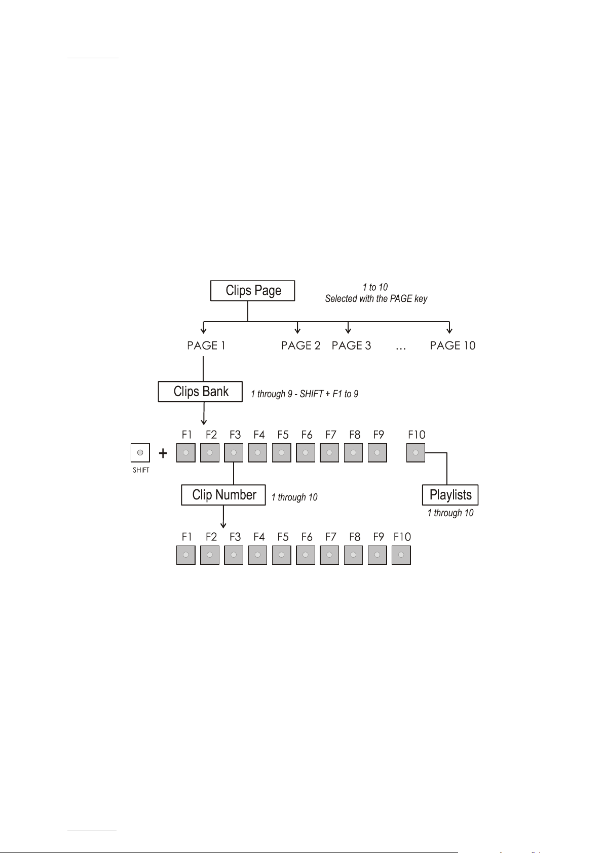
4.2 SELECTI ON OF CLIP BANKS AND PLAYLISTS
SHIFT + F1 - F9 = CLIPS BANK
This allows access to clip banks 1 through 9 within the clip page (1 to 10).
SHIFT + F1 = BANK 1
SHIFT + F2 = BANK 2, etc. (up t o bank 9)
Once in the bank, selection of the F1 – F10 keys will call up the respective clips.
If Recal l Clip Toggle is enabled in t he Setup menu, pr essing several times on the
same F_ key will c all successively all c amera angles of that clip.
The clip numbering system is as follows :
Example: Clip 547 where
• “5” refers to the clip page number (1 t o 10).
• “4” refers to the clip bank (1 to 9)
• “7” refers to the clip number (1 t o 10) inside the bank
Note
To ident ify remote clips when using t he XNet SDT I network, t he number of
the clip is followed by the number of the machine on the network. i.e. Clip
547B/04
SHIFT + F10 = pla yli st B AN K
This combination of keys gives access to the playlists’ banks. Within each clip
page there are 10 playlists. Selecting F1-F10 at this point calls up the
corresponding playlist.
Example: Playlist 51 where
• “5” refers to the clip page
• “1” refers to the playlist number (1 to 10)
Note
• The playlist bank of page 10 is not available from the EVS remote,
since it is actually reserved for the EVS AVSP protocol (for Air Box
and Air Edit).
• To identify remote playlists when using the XNet SDTI network, the
number of the playlist is followed by the number of the machine on the
network, i.e. Playlist 51/04
Page 32
Issue
10.04.A
EVS Multicam Vers ion 10.04 – Operating Manual
22
4.3 CLIP NUMBERING HIERARCHY
Multicam can store up to 900 (multiplied by the number of cameras) clips and 100
playlists in its libraries. 900 clips with up to 6 camera angles per clip results in
5400 clips on a server. This number is displayed in the upper right window of the
VGA Setup screen (SHIFT+F2 from the PC k eyboard).
If you are working with XNet SDTI network, keep in mind that the total number of
clips on the entire network is limited to 6,000 or 16,000, d epend ing on the network
settings. This number is displayed in the same area on t he V GA Setup window.
The following diagram represents the hierarchy of the Multicam clip numbering
system. As an example, clip number “112” is used:
EVS Broadcast Equipment SA – January 2011
Page 33

EVS Mult icam Version 10.04 – Operat ing Manual
EVS Broadcast Equipment SA – January 2011
Issue
10.04.A
23
5. Control Mode
Multicam can be set in three different basic modes, depending on commands used.
5.1 LIVE (E2E) M ODE
This mode selected at start-up can also be selected by pushing the RECORD key.
Multicam records the input signal and plays it at the same time on the program
output.
5.2 SEARCH MODE
This mode is selected by moving the jog d ial.
In this mode, the operator has the opportunity to search for an image, in order to
define cue points or clips. Moving the command knob clockwise will force Multicam
to search forward, moving the command knob counter clockwise will force it to
search backwards. The most important thing to note is that Multicam never stops
recording while searching.
5.3 PLAYBACK MODE
Moving the lever or pressing the PLAY key selects this last mode.
Multicam plays the incoming signal delayed, a clip or a playlist, in slow motion,
and of course, continues to record the incoming signal on disks.
As soon as the lever is moved, Multicam starts playing back from the current
picture. The playback speed is d efined by the lever position. This is used to start
the playback of a normal slow motion, as well as the playback of a clip or a
playlist. During playback, the system never stops recording
Each operation on the Remote Panel with the command KNOB or LEVER will be
associated to the Search or Playback mod e respectively.
Page 34
Issue
10.04.A
EVS Multicam Vers ion 10.04 – Operating Manual
24
Cue In1
Clip B
Clip A
Clip C
Clip D
Cue In2
Cue In3
Cue In4
Cue In1
Cue In2
Cue In3
Cue In4
EVS Broadcast Equipment SA – January 2011
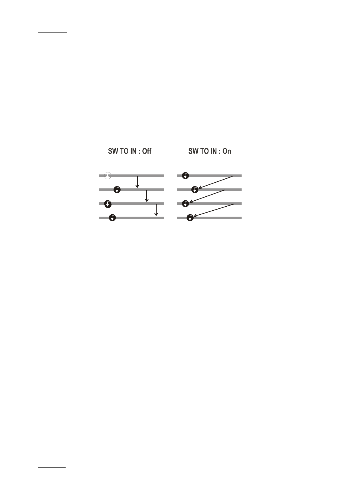
5.4 SYNCHRONISATION MODE (SWITCH TO IN)
If the synchronization mode is OFF, a request for camera change will produce a
jump at the same timecode on the requested camera. This mode allows
synchronous chang e of camera angle.
If the synchronization mode is ON, a request for a camera change (by pressing
CAM A, CAM B CAM C or CAM D in the Multicam menu) will lead to a jump to a
predefined CUE IN point.
If a CUE IN point has not been previously defined, Multicam acts as in SW to IN
OFF mode (even if SW to IN ON is shown) because the system has no reference to
jump to.
Page 35

EVS Mult icam Version 10.04 – Operat ing Manual
EVS Broadcast Equipment SA – January 2011
Issue
10.04.A
25
5.5 DEFINITION OF CONT ROLLED AND PRIMARY CHANNELS
Important
The notions of Primary Channel and Controlled Channel are very
important and will be constantly referred to in this m anual.
5.5.1 CONTROLLED CHANNEL
A channel is “controlled” when the operator can control it with the jog dial. In this
case, the words “FULL CTRL” are present on the top of the OSD of the output
monitor of that channel.
5.5.2 PRIMARY CHANNEL
The primary channel is the first controlled channel. It is identified by stars around
its name on the OSD of the output monitor and on the LCD display of the Remote
Panel (ex: *PGM1*).
Examples:
• In 3PGM mode, if the operator controls PGM2 and PGM3, the primary channel
is PG M2.
• In PGM+PRV mode with PRV CTRL OFF, the primary channel is PGM.
• In PGM+PRV mode with PRV CTRL ON, the primary channel is PRV.
5.6 PREFERENCE MO DE (PREF)
When this option is ON and a clip is recalled, the preferred camera will be
displayed on the main out put, even if another camera ang le was previously loaded
on that output.
The preferred camera is the one, which was on the primary output channel when
the clip was created.
The second preferential camera (“secondary camera”) is the one that was loaded
on the next channel when the clip was created.
In the Clip screen, the first preferential camera is indicated by a star: 111B* and
the second preferential camera is indicated by 2 dashes: 111B=.
When the preference option is disabled, the PGM output stays on the camera
currently selected when the clip is called .
Page 36

Issue
10.04.A
EVS Multicam Vers ion 10.04 – Operating Manual
26
EVS Broadcast Equipment SA – January 2011
5.7 SECONDARY CONTROLLER
5.7.1 INTRODUCTION
The 2nd CTRL function available on the Remote Panel in the main operational
menu allows the operator to swap the control of one or several play channels
between the EVS Remote Panel and a third-part y cont roller.
Both controllers receive permanently the status of the channel(s), but only one
controller at a time is able to actually control a channel: this is called the
exclusive secondary control mode. The secondary controllers are defined in
Section 7 of the Remote Setup menu.
5.7.2 INTERACTIONS BETWEEN IPDP AND MULTICAM
When a Remote Panel and an IPDirector share the control of some PGMs in
exclusive secondary control mode, the following principles apply:
• When a playlist/timeline is controlled by the Remote Panel on a PGM, the
playlist/timeline remains the current one when IPDirector is given the control
on the P GM.
• When a playlist/timeline is controlled by IPDirector on a PGM, the
playlist/timeline remains the current playlist on the Remote Panel when the
operator takes back the PGM control.
• When several playlists /timelines have been contr olled by IPDirector on several
PGMs and the operator takes back the PGM control, the current
playlist/timeline on the Remote Panel is the one that was the current playlist
when the control was given away, in other words the current playlist/timeline
does not change.
• When the playlist/tim eline cont rolled by IPDirector is not visible by the Remote
Panel, the current playlist/timeline on the Remote Panel is the one that was
the current playlist when the control was given away, in other words the
current playlist/timeline does not change.
Page 37
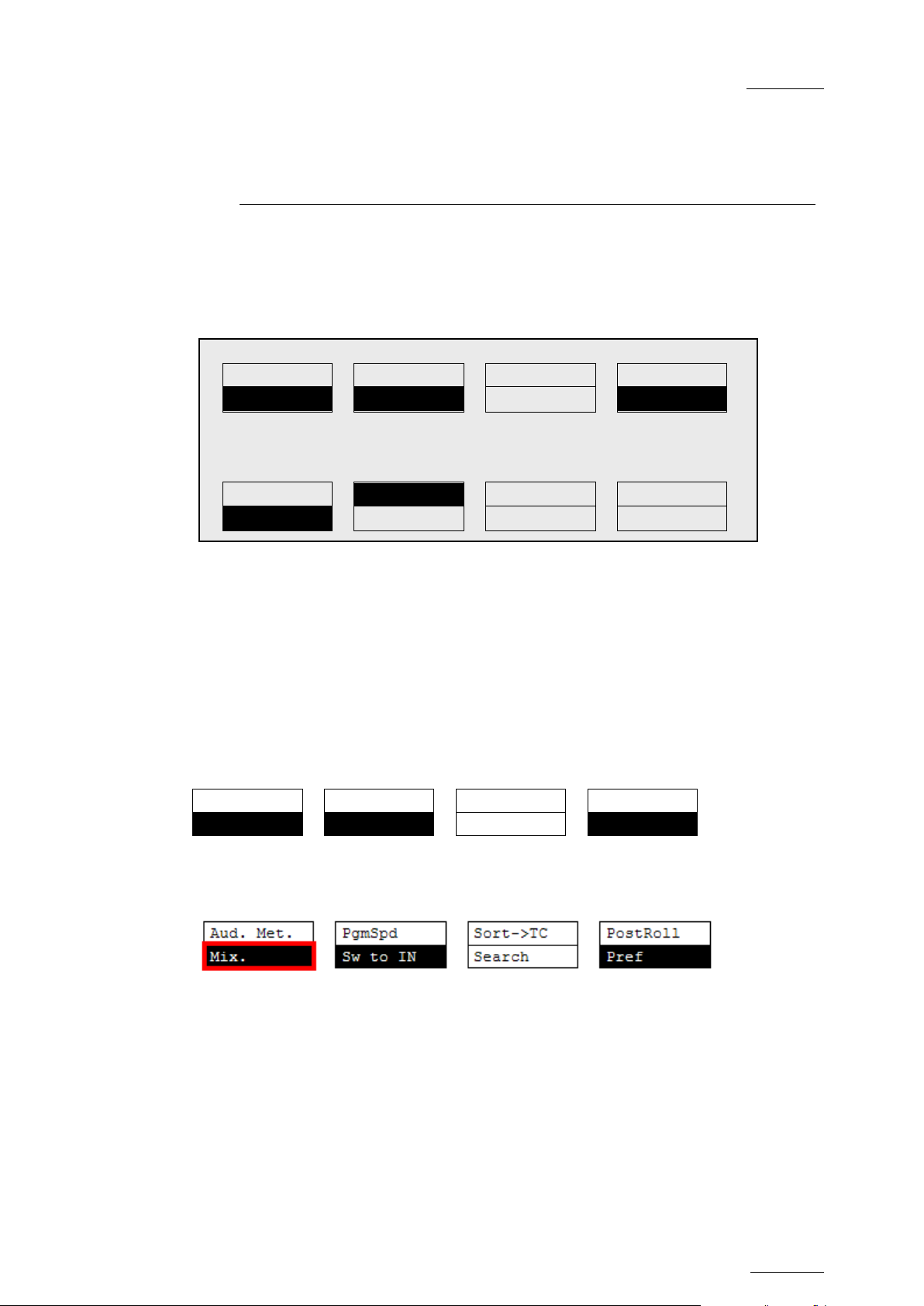
EVS Mult icam Version 10.04 – Operat ing Manual
EVS Broadcast Equipment SA – January 2011
Issue
10.04.A
27
Aud. Met.
PgmSpd
Sort->TC
PostRoll
Mix.
Sw to IN
Search
Pref
PGM1 CAM A *PRV1* CAM B
Aud.Met.
PgmSpd
Sort->TC
PostRoll
Mix.
Sw to IN
Search
Pref
Rst Cam
Local
Sync Prv
2nd CTRL
Cam A
Cam B
Cam C
Cam D
6. PGM-PRV Mode
6.1 1PGM+ PRV (PRESS A FROM MAIN MENU)
P.1 B.1 Clips: LOCAL Record s: LOC AL
PL 11: <
Msg:
At least 2 playback channels must be available to run this configuration.
This mode allows the operator to make replays with/or without transition effects
between all outputs . A str ing of replays can be put t ogether and played back at the
operator’s d iscretion.
The LCD display is divided in two menus controlled by soft keys (A,B,C,D). To
gain access to the upper menu, press MENU from t he Rem ote Panel.
6.1.1 SECONDARY MENU
Mix / Wipe L> R / Wipe R>L / Wip e U>D / Wipe D>U / Cut
These options d etermine the transition eff ect that will occur betw een the PGM and
PRV pictures. The mix, wipe and cut are on the same location. Pressing this
button will browse throug h these eff ects, showing the ac tive one on the LCD menu.
Please refer to Setup menu to selec t the d uration of the transition effect.
Page 38
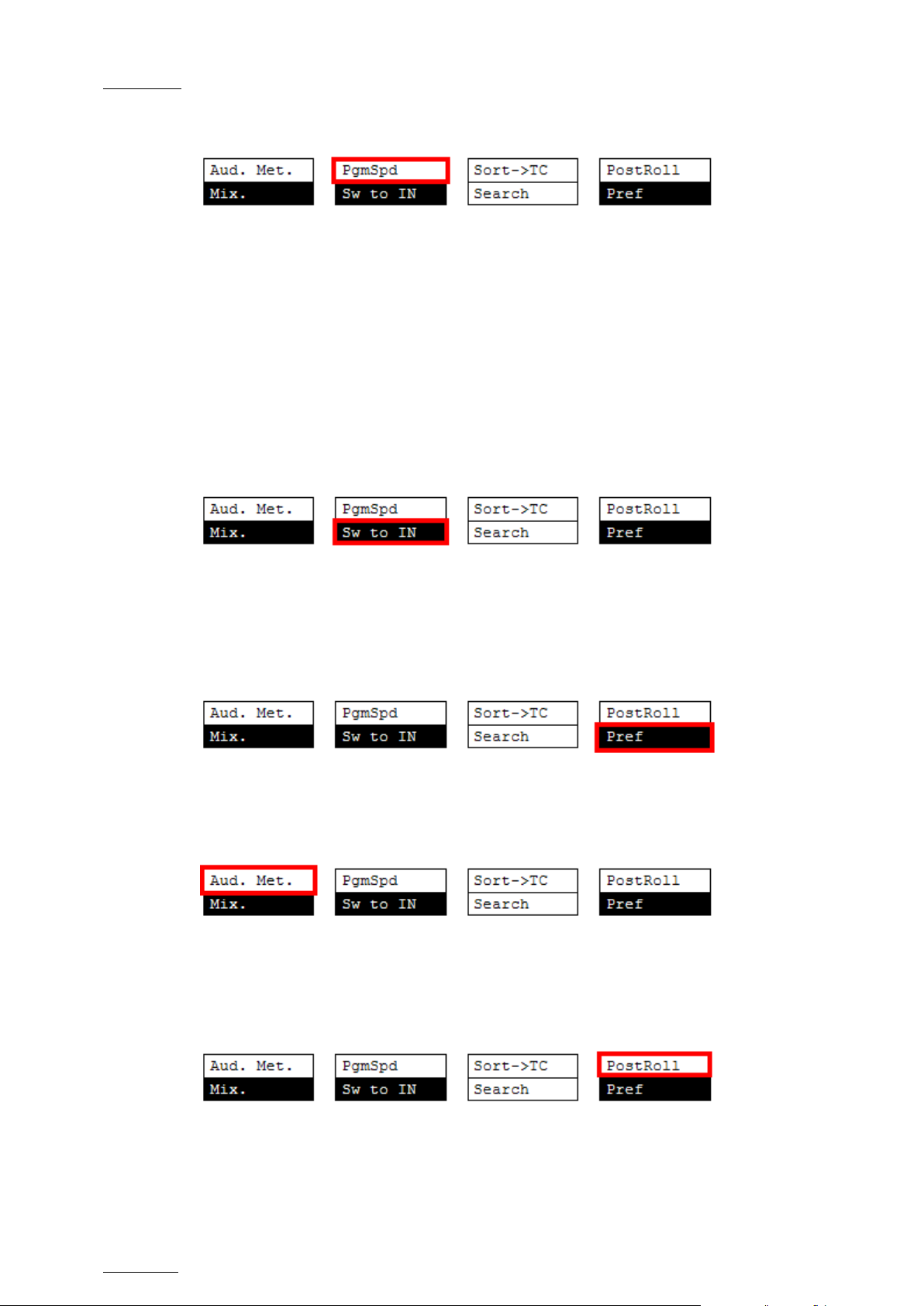
Issue
10.04.A
EVS Multicam Vers ion 10.04 – Operating Manual
28
EVS Broadcast Equipment SA – January 2011
PgmSpd/VarMax
Pressing PgmSpd once enables the Program Speed mode and highlights this
function on the LCD. Pressing the key once more enables the Var Max mode and
highlights this function on the LCD. The PLAY key is flashing red while either of
these modes is enabled.
• Program Speed mode: In this mode, only two speed va lues are available from
the lever: 0% when the lever is in the lower position, or the speed defined in
the setup (p.6.1 F3) for any other position of the lever.
• Var Max mode: the speed range defined by the lever is limited between 0%
and the s peed value defined in the setup (p. 6.1 F3).
Sw To In
When this funct ion is enabled (highlighted) , a camera change will cause a jump to
the corresponding IN point if existing. It will switch in Sync if no IN point exists for
the current element, or if SW to IN is OF F.
Pref
Selecting this function enables t he Preference mod e.
Aud.Met.
This option enables/d isables the display of audio met ers for all channe ls using the
OSD of the output monitors.
PostRoll
When the Post-Roll mode is enabled, t hat function is highlighted on the LCD and a
“P” appears on the OSD of the output monitors.
When the user exits Multicam with the Post-Roll mode on, this mode will still be
Page 39
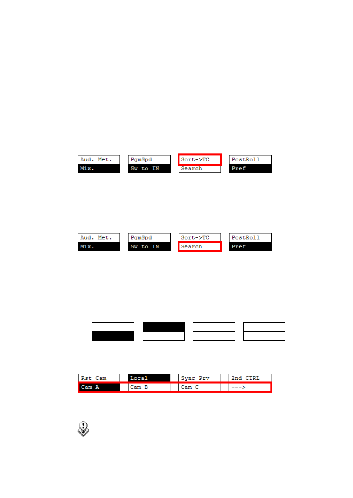
EVS Mult icam Version 10.04 – Operat ing Manual
EVS Broadcast Equipment SA – January 2011
Issue
10.04.A
29
Rst Cam
Local
Sync Prv
2nd CTRL
Cam A
Cam B
Cam C
Cam D
In 5CAM configuration (5 recorder channels and 1 player channel) or
enabled when Multicam is restarted.
The Post-Roll mode works as follo ws depending on the elem ent played :
• When a clip is played, it will not st op on the Short OUT point, but will continue
to play through the Short OUT point by the Post-Roll duration defined in the
Setup Menu.
• When a record t rain is played , the same will happen if the Record Train OUTs
parameter is set to “Freeze” in the Setup menu.
• When a playlist is played, the Post-Roll will apply only to the last clip of the
playlist.
Sort->TC
This function allows the operator to search for all clips that contain a particular
timecode. For more information on this function, refer to the section ‘Sort->TC’, on
page 49.
Search
This function allows the operator to search the database using keywords and
ranking. Refer to the section 10 “Keyword Management” on page 72 for further
details.
To return to the operational menu, press th e MENU key from the Remote Panel.
6.1.2 OPERATIONAL MENU
CAM A/ B /C / D
This paramet er allows selecting t he camera on the PGM output if PRV CTL is OFF
and on PRV output if PRV CTL is ON.
Note
when loading a clip where CAM E or F exists, the operational menu will
display:
Page 40
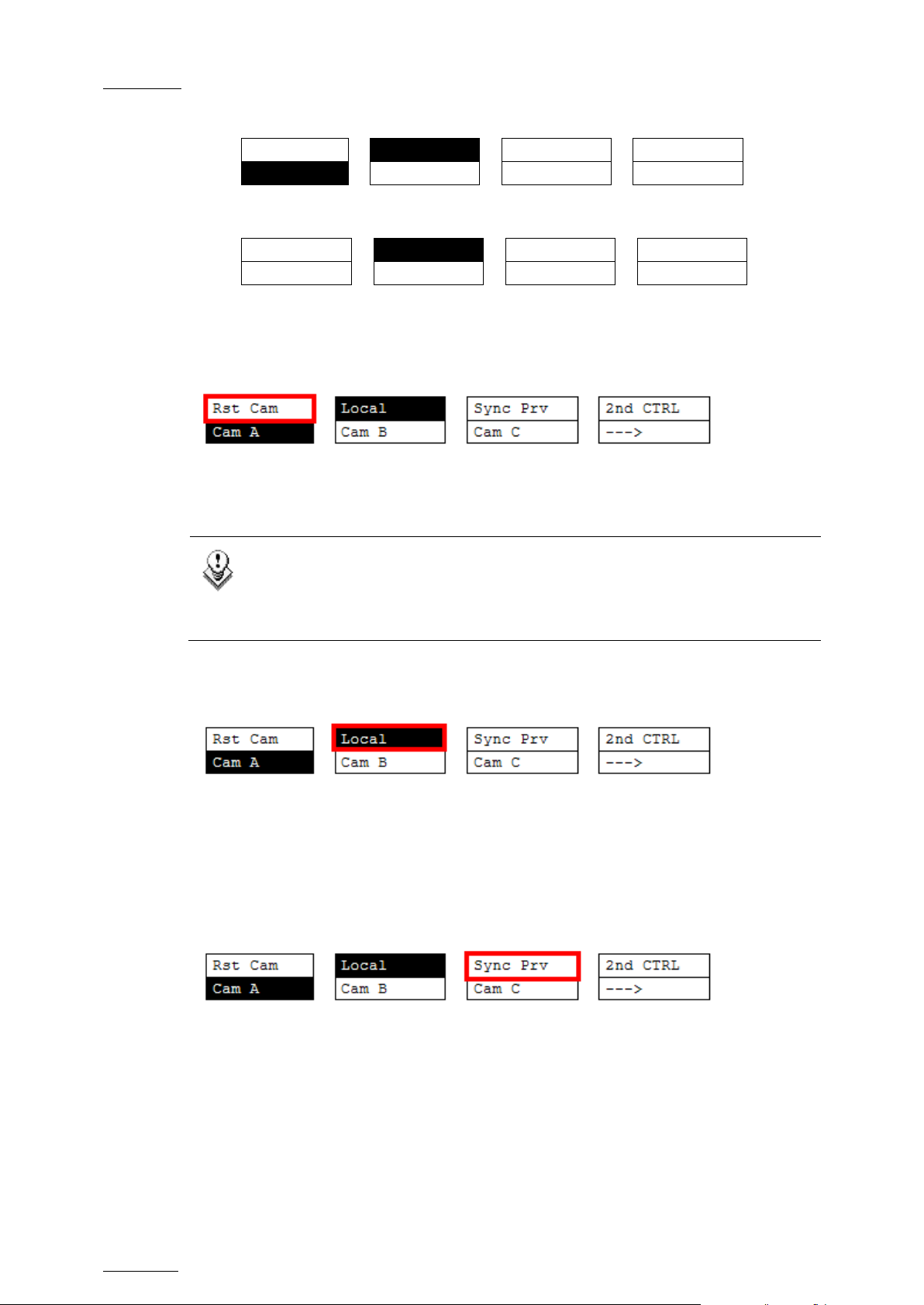
Issue
10.04.A
EVS Multicam Vers ion 10.04 – Operating Manual
30
Rst Cam
Local
Sync Prv
2nd CTRL
Cam A
Cam B
Cam C
--->
Rst Cam
Local
Sync Prv
2nd CTRL
Cam D
Cam E
Cam F
<---
EVS Broadcast Equipment SA – January 2011
By pressing the D key (--->), the operator has access to the D, E and F
cameras. The operation menu becomes:
Press the D ke y (<---) to return to CAM A, B, C selection.
Rst Cam
This function restores the position of cameras on the active channels: CAM A on
PGM1, CAM B on PRV.
Note
When a clip/playlist is loaded on a channel, switching back to Live mode
will recall the record train, which was last used on that output. This
avoids too frequent uses of the RST CAM function.
Local
This function allows the user to reconnect to the local LSM after having accessed
distant clips or record trains. The function is highlighted when the user is
connected to bot h clips and record trains on t he loc al LSM. It is d isplayed only on
Master/Ser ver LSMs when they are connected to the SDTI network.
Sync Prv
This option allows t he user to synchronize t he PRV with t he timecode and speed of
the PGM output. This function is not availab le with remot e r ecord trains.
Page 41
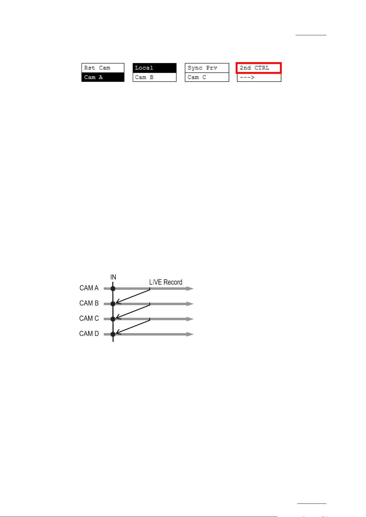
EVS Mult icam Version 10.04 – Operat ing Manual
EVS Broadcast Equipment SA – January 2011
Issue
10.04.A
31
2nd CTRL
This function allows the operator to swap the control of one or several play
channels between the EVS Remote Panel and a third-party controller. Both
controllers receive permanently the status of the channel(s), but only one
controller at a time is able to actually control a channel. The secondary controllers
are defined in Section 7 of the Remote Setup menu.
Press this function to enter the 2nd CTRL m enu, select the channels that you want
to pass to the secondary controller by pressing the corresponding A or B key, then
press D (DONE) to validate your selection. Do the same to bring the control of a
channel back to the EVS remote.
6.2 FULL CONTROL AND LEVER CONTROL
Controlling both PG M and PRV is done when PRV CT L (direct access key from t he
remote) is not activated.
Once selecting PRV CTL the operator will have control of the PRV with the jog dial
and most buttons, while the lever a nd the Play button wi ll c ontrol the PGM out put.
At this point, selecting clips will ca ll them up on t he PRV side.
The combination of the PRV CTRL and the SW to IN functions allows the operator
to auto-chain cameras from the same IN point.
When an IN point has been marked, the operator activates the PRV CTL and sets
ON the SW to IN option. Then the slow motion of one camera can be started from
this IN point. The operator selects another camera in the PRV output and, via the
TAKE button, can auto-chain cameras from the same IN point on the PGM output.
Page 42

Issue
10.04.A
EVS Multicam Vers ion 10.04 – Operating Manual
32
PGM1 CAM A *PGM2* CAM B PGM3 CAM C
Aud.Met.
PgmSpd
Sort->TC
Post-Roll
Sw to IN
Search
Pref
Rst Cam
Local
Sync To
2nd CTRL
PGM 1
PGM 2
PGM 3
TOGGLE
EVS Broadcast Equipment SA – January 2011
7. Multi PGM Mode
7.1 1/2/3 PG M MODES (PRESS A OR B FROM MAIN MENU)
Multicam has two modes for its basic operation, 1 PRV/PGM mode or Multi PGM
mode:
• The 1PGM+PRV mode, as described previously, is the more powerful of the
two, allowing for interaction between all outputs. Here, synchronized replays
can be rolled and chained between the c ameras with either a mix, wipe, or cut
between them.
• The MULTI PGM mode is more basic, which gives the operator independent
control of all outputs.
In this mod e, all outputs c an be controlled together (such as jogging back to a
certain action, with all outputs) or they can be controlled individually (either
PGM 1, 2 or 3).
P.1 B.1 Clips: LOCAL Record s: LOC AL
PL 11: <
Msg:
7.1.1 SECONDARY MENU
The secondary menu can be c alled by pressing the MENU key and is s im ilar t o the
1PGM+PRV mode, except that the A function is empty since it is not possible to
create a tr ansition between t he channels in this mode. Please refer t o the Chapter
6 ‘PGM-PRV Mode’, on page 27 for description of the other functions of the
secondar y menu.
Page 43
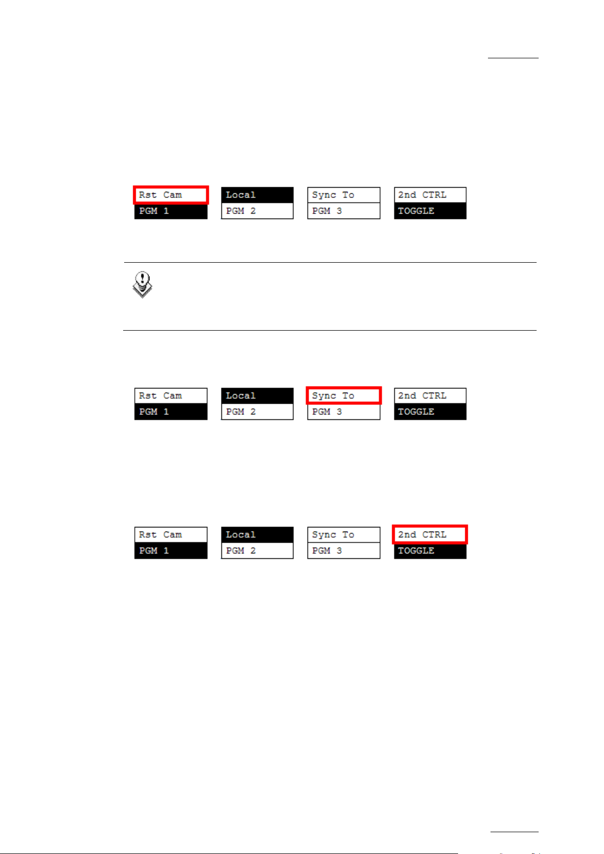
EVS Mult icam Version 10.04 – Operat ing Manual
EVS Broadcast Equipment SA – January 2011
Issue
10.04.A
33
7.1.2 OPERATIONAL MENU
The operational menu in Mu lt i PGM mode gives acc ess to the functions detailed in
the following paragraphs:
Rst Cam
This function restores the position of cameras on the active channels: CAM A on
PGM1, CAM B on PGM2, etc.
Note
When a clip/playlist is loaded on a channel, switching back to Live mode
will recall the record train, which was last used on that output. This
avoids too frequent uses of the Rst Cam function.
Sync To
This button allows you to synchronize the selected PGM in use with another one.
Press this button and then select the PGM to be used as a reference. This
function is not available with network trains.
2nd CTRL
This function allows the operator to swap the control of one or several play
channels between the EVS remote and a third-party controller. Both controllers
receive permanently the status of the channel(s), but only one controller at a time
is able to actually control a channel. The secondary controllers are defined in
Section 7 of the remote Setup Menu.
Press t his function to enter the 2nd CTRL menu, select the channels that you want
to pass to the secondary controller by pressing the corresponding A, B or C key,
then press D (DONE) to validate your selection. Do the same to bring the control
of a channel back to the EVS remote.
Page 44

Issue
10.04.A
EVS Multicam Vers ion 10.04 – Operating Manual
34
The 1PGM mode is a simplified version of the 2 or 3PGM modes. The
Local
2nd CTRL
Cam A
Cam B
Cam C
Cam D
Rst Cam
Local
CAM A
CAM B
CAM C
CAM D
EVS Broadcast Equipment SA – January 2011
Note
operational menu has less functions:
Also, the user does not need to select a channel to enable or disable the
secondary controller. Since there is only 1 channel available in this
mode, the operator just has to press SHIFT + D to swap the control
between the secondary controller and the EVS remote.
Tog gle / All
The Toggle function is only ava ilable in 3PGM mode:
• Toggle OFF: Selecting an output channel results in controlling that channel
and disables the control on others.
• Toggle ON: Selecting a channel will alternatively enable/disable the control
over that channel without changing the control on the others.
• All: This enables the control on all c hannels.
How to Assign a Camera to a Channel
In Multi PGM mode, you can change the current camera on each PGM as follows :
1. In the operational menu, select the PGM to which you want to change the
current camera.
The TAKE key at the bottom of the remote is lighting red.
2. Press the TAKE key.
It lights green and the menu on the LCD display changes to let you selec t the
desired camera.
3. Press the camera you want to associate to the selected PGM.
4. Press TAKE again to return to the PGM selection menu.
Page 45

EVS Mult icam Version 10.04 – Operat ing Manual
EVS Broadcast Equipment SA – January 2011
Issue
10.04.A
35
Playl ist Cond itional Mode
This mode is only available in 2PGM and 3PGM modes. It allows the operator to
load and control several playlists simultaneously from the same Remote Panel, or
to load a playlist on one channel while performing other operations on the other
channel(s). To use this mode, the “Load Playlist” parameter of the setup menu
must be set to “Conditional” (p. 4.2 F5).
To use this mode, select one channel (for example PGM1), and press the PLST
key once, twice or three times to enter the PLST EDIT or the PLST DIFF mode
(refer to the “Pla ylist Management” Section of this manual for details about these
modes). Y ou can notice that the TAKE key button lights gr een. Pressing the TAKE
key will allow the operator to return to the PGM selection menu, and select
another PGM channel where he can start a replay, load a clip or another playlist,
etc.
In this mod e, if the operator selects a PGM c hannel where a p laylist is loaded and
presses t he TAKE key, he will enter again the PLST EDIT or PLST DIFF mode.
When playlists are loaded on all channels currently controlled by the operator in
MULTI PGM mode, the TAKE key lights red. If the TAKE key is pressed, the
remote will enter a specific PLST DIFF mode, where the operator can control
several playlists simultaneously, and browse them or roll them in sync. NEXT and
SKIP functions are also available and will apply on all controlled playlists. The
TAKE button will not light red if one of the controlled channel does not contain a
playlist.
Pr acti cal e xampl e
The operator builds a playlist with Fills and another playlist with Keys. He sets t he
“Playlist Load” parameter to “Conditional” in the setup menu, then enters the
2PGM m od e, selects t he Fills playlist as current playlist, presses A to gain control
on PGM1, presses PLST two or three times to enter the PLST DIFF mode and cue
up the Fills playlist to its 1st clip. Then he presses the TAKE key to return to the
PGM selection menu, selects the Keys playlist as current playlist, presses B to
gain control on PGM2, presses PLST two or three times to enter the PLST DIFF
mode and cue up the Keys playlist to its 1st clip. Then he presses the TAKE key
to return to the PGM selection menu, presses D to gain control on both PGM
channels, then presses TAKE to enter the PLST DIFF menu. He will see on the
LCD screen the content of both playlists side by side, and can browse them or
play them in Sync at any speed, and perform SKIP and NEXT commands as
needed.
Page 46

Issue
10.04.A
EVS Multicam Vers ion 10.04 – Operating Manual
36
EVS Broadcast Equipment SA – January 2011
8. Video Delay
When the Multicam software has been configured with a base configuration =
Video Delay in the Channel Parameters menu, the Delay Screen will appear
automatically when the application is started. In this case, all play channels will
be available from the Delay screen.
If Multicam is running a base configuration different than Video Delay, this screen
can be called manually from t he Clip s creen, Playlist Screen or Net work Screen by
pressing SHIFT-F7 on the keyboard. In this case, only the play channels assigned
to user #1 (i.e. the 1
maXS, or the 1
st
protoc ol if the base configuration is in slave mode).
st
EVS Remote Panel if the base configuration is LSM or
For each play channel, the operator can adjust:
• the video and audio source (camera angle, and source server if several units
are connected on an SDTI network);
• the des ired delay in hh:mm:ss:fr.
For each play channel, the operator can view:
• the actual delay in hh:mm:ss:fr;
• the timec ode of the on-air picture
• the timecode of the incoming picture on the associated record channel;
• the status of the associated record channel (Recording / Id le)
Page 47

EVS Mult icam Version 10.04 – Operat ing Manual
EVS Broadcast Equipment SA – January 2011
Issue
10.04.A
37
How to Configure the Video Delay Parameters of a Play Channel
1. Select the play channel to configure by pressing ALT+ the corresponding F_
key on the PC keyboard (ex: ALT+F1 f or PG M1, ALT+F2 for PG M2/PRV, etc)
2. If you want to use another server on the SDTI network as a source, press
SHIFT-F7 on the PC keyboard to call up the network list. Use the arrow keys
to select a server, and press ENTER to validate.
3. Select the camera angle: use the left / right arrow keys, or the <TAB> key to
move the green cursor on the desired camera, the press ENTER. The new
camera angle is loaded on the channel.
4. Set the new va lue f or the delay: use the l eft / right arrow keys, or the <TAB>
key to move the green cursor over the TARGET DELAY field, and enter the
desired delay value in hh:mm:ss:fr. Press CTRL + the cor responding F_ key on
the PC keyboard to activate the new delay on the selected channel (ex: CTRL
+ F1 start the new delay on PGM1). If the duration of the record train is lower
than the targ et delay, the channel will pause on t he first record ed picture until
the record train is long enough for the desired delay. In this case, the
message “WAIT” is displayed on the OSD of that channel.
Page 48
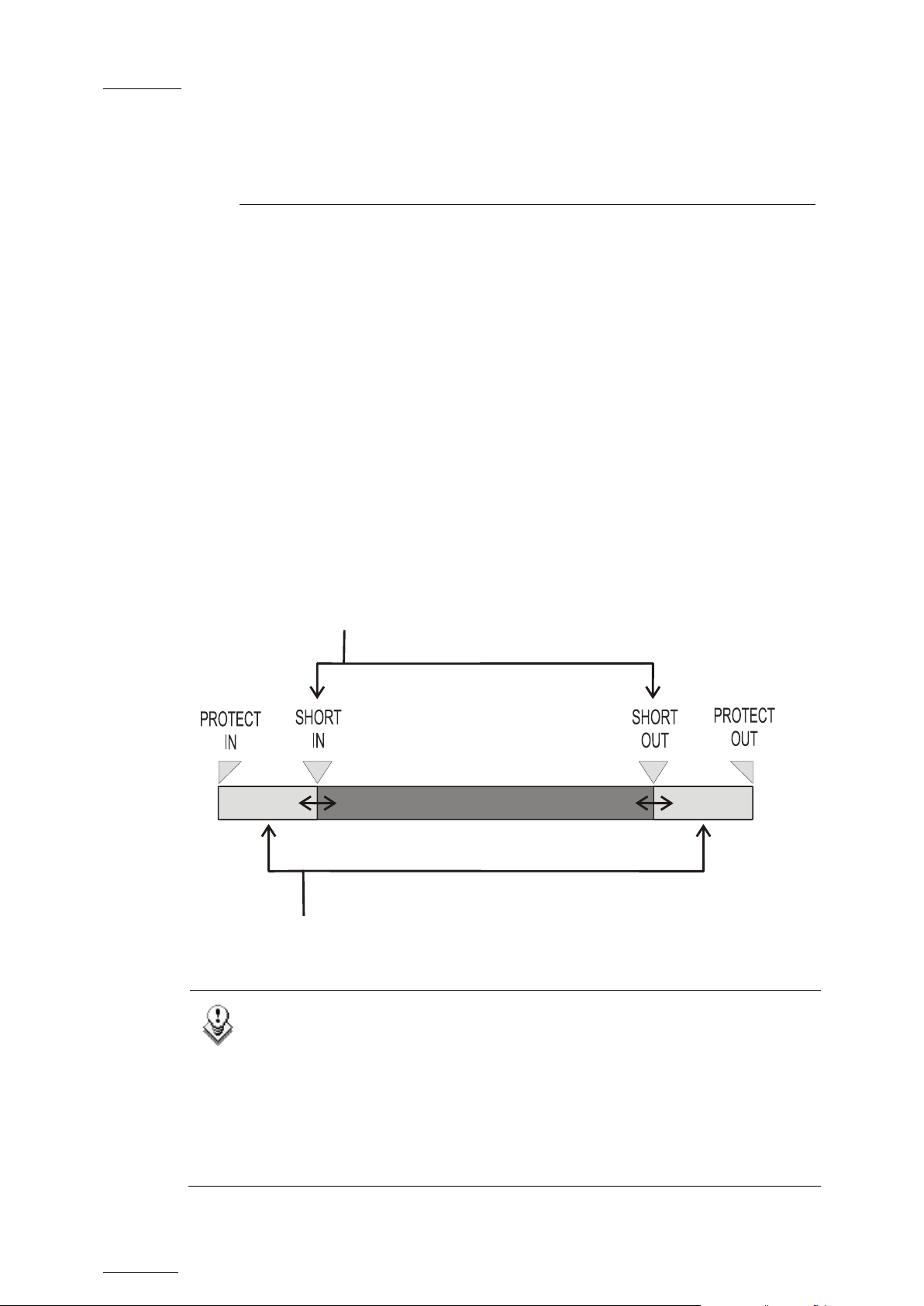
Issue
10.04.A
EVS Multicam Vers ion 10.04 – Operating Manual
38
9. Clip Management
9.1 INTRODUCTION
9.1.1 CLIP STRUCTURE
A clip is defined by Short IN and Short OUT points. When referring to Short IN and
Short OUT points, the operators usually us e the terms IN point and OUT point.
When Short IN and Short OUT points are set, the system automatically write
protects a user definable length of material before and after the Short IN/OUT
points respectively, these are ref erred to as the g uardbands.
For this reason, the IN point before the guardbands and the OUT point after the
guardband are called Protect IN point and Protect OUT point.
EVS Broadcast Equipment SA – January 2011
It is possible to trim a c lip by red efining Short IN and S hort OUT points.
If Short IN and Short OUT points are defined, only the fields between those two
points will be played if the sequence is recalled (the same applies when the
sequence is included in a playlist).
Fields between P rotect IN and Short IN and fields bet ween Short OUT and Protect
OUT (guardbands) can be reached with the jog. So the Short IN and Short OUT
points can be redefined.
Note
• Protect IN & Protect OUT points of a clip cannot be replaced by new
ones.
• Short IN & Short OUT points of a clip can be replaced by new ones.
• Short OUT point is excluded. The clip freezes on previous field when
playing back (with Post-Roll disabled).
• (Short ) IN & OUT are always on even fields. This is automatic.
Page 49

EVS Mult icam Version 10.04 – Operat ing Manual
EVS Broadcast Equipment SA – January 2011
Issue
10.04.A
39
The guardband beyond the Short OUT point is created with the
•
material available when the operator saves the clip by pressing the
selected F_ key. Therefore, this guardband can sometimes be shorter
than the value defined in the Setup menu.
9.1.2 CLIP AVAILABILITY ON DISKS
Various clip types can be distinguished depending on whether they are available
on the disks or not. Depending on the clip availability on disks, you can perform
specific actions on the given clip or not.
Clip on disk
Growing clip
Reserved clip
Clips which are protected on disks, and which have Short
IN and Short OUT points present on d isks.
All the material is availa ble on the disk.
Clips which are protected on d isks, and which have a Short
IN point, and possibly Short OUT point defined on disks.
Since the record process is still undergoing, some of the
material is already on the disk but not all of it.
Clips for which the posit ion has been reserved on the SDTI
database but for which there is no Short IN and Short OUT
points, nor any protect present on disks.
9.2 USING T HE EVS REMOTE PANEL
9.2.1 HOW TO CREATE A CLIP
To define a clip, proceed as follows:
1. Select the LIVE mode.
2.
Using t he jog dial, def ine your Short IN point . Press the IN k ey to mark your
Short IN point of the clip.
3.
Search for the desired S hort OUT point and t hen press the OUT key to m ark
it.
A clip can be created with only IN point or only OUT point. The system will
automatically define the clip duration according to the default duration defined in
the Setup menu.
Note
You can mark an IN or OUT point on a paused record train and go back to
live without losing the point marked by pressing SHIFT-<Return>.
Page 50

Issue
10.04.A
EVS Multicam Vers ion 10.04 – Operating Manual
40
9.2.2 STORING A CLIP
HOW TO STORE A CLIP
To store a clip on a given location, proceed as follows:
1. Define a clip by marking the IN and/or OUT points
2.
Select the page where the clip will be stored by pressing SHIFT + PAGE +
F_ key corresponding to the page.
Page 1 contains clips 110 to 199. Page 2 contains clip 210 to 299, and so
on.
3.
Select the bank where the clip will be stored by pressing SHIFT + F_ key
corresponding to the bank.
4. Select the location of the clip to store by pressing the corresponding F_ key.
The clip is created on the specified location. The primary timecode of the clip is
the primary timecode defined on the train where and when the clip has been
created.
EVS Broadcast Equipment SA – January 2011
EXAMPLE
To create the clip on the position n°212 (page 2, bank 1, clip location 2):
1. Press SHIFT+PAGE+F2 t o s elect page 2.
2. Press SHIFT+F1 to select bank n°1.
3. Press F2 to select location n°2 on the select ed page and bank.
Important
The AUTO-SAVE process automatically saves clips and playlists
at least every minute. With Multicam 5.03.25 or higher, playlists
are included in the AUTO-SAVE process. Exiting the software
(ALT+Q) or doing “Save Clips+Plst” from the main menu will also
save the clips and playlists.
Page 51

EVS Mult icam Version 10.04 – Operat ing Manual
EVS Broadcast Equipment SA – January 2011
Issue
10.04.A
41
9.2.3 RECALLING A CLIP
HOW TO RECALL A CLIP
To recall a clip, proceed as follows:
1. Select the Clip page 1, 2, 3, … to 10 (PAGE key).
2. Select the bank in which the desired clip is located
3. Select the desired clip via the F1 - F10 keys.
CLIP RECALLED BASED ON THE PREF SETTING
If PREF is ON, the preferred camera angle of the clip will appear on the primary
channel, the secondary camera angle on the next controlled channel, then the
other camera angles on the next channels in alphabetical order.
Example: If the preferr ed camera angle for clip 124 is camera C, when loading the
clip, 124C is loaded on the primary channel, whatever the camera present on that
channel before loading the clip.
If PREF is OFF, when recalling the clip, the camera angle will be the same as the
one who was already present on each controlled channel. If that camera angle
does not exist, the first availab le camera angle of the clip will be used .
Example: If camera B is the current camera on the primary channel, when calling
clip 124, it is 124B that appears on the primary channel, even if it is not the
preferred camera angle.
When the operator is controlling only one channel (such as with PrvCtl), the clip
will appear at that location only. In the case of a clip containing a single camera
angle (only an «A», «B», «C» or «D» clip), when in full control of a ll outputs, the
clip recalled will appear on the primary channel.
TOGGLING BETWEEN THE CAMERA ANGLES
If “Recall Clip Toggle” is enabled in the Setup Menu, pressing several times the
F_ key will always recall the first frame of the clip, but showing the next camera
angle every time the F_ key is pressed.
Page 52

Issue
10.04.A
EVS Multicam Vers ion 10.04 – Operating Manual
42
9.2.4 PLAYING BACK A CLIP
PLAYBACK SPEED FEATURES
You can play back a clip using several playback speed features explained above
in this user manual. This section summarizes the various playback speed features
and ref ers to more detailed sections on thes e features:
• Playback of a clip at the default playback speed using the PLAY key
• Playback of a clip at a speed varying from 0% to 100% using the Lever in a
basic way
• Playback of a clip at a speed varying from 0% to a maximum speed defined in
the PGM Spd/Var Max setting on the Remote Panel (Pg. 6.1, F3).
To use this feature, you need to activate t he VarMax option available from t he
secondary menu in PGM/PRV mode. For more information, refer to the section
‘PgmSpd/VarMax’, on page 28.
• Playback of a clip at a given predefined speed defined in the PGM Spd/Var
Max setting on the Remote Panel (Pg. 6.1, F3).
EVS Broadcast Equipment SA – January 2011
To use this feature, you need to activate the PGM Spd option available from
the secondary menu in PGM/PRV mode. For more information, refer to the
section ‘PgmSpd/VarMax’, on page 28.
HOW TO PLAY BACK A CLIP
To play back a clip, proceed as follows:
1. Store a clip.
2.
Recall the defined clip which will be played, the corres pond ing F_ k ey lights
red.
3. To start playing back the clip, press the PLAY key or use the lever.
9.2.5 RECALL AND PLAYBACK OF GROWING CLIPS
You can recall and play growing clips, i.e. clips that are in the process of being
created on a disk.
As long as the O UT point of a gr owing clip is not available on t he EVS server, the
LED correspond ing to the growing clip location blinks green when it is called and
red when it is loaded on the Remote Panel. The clip LED will no longer blink as
soon as both IN and OUT points are available on the EVS server.
If the play reaches the end of the available m aterial, the play will freeze unt il new
material is available for playout. When new material is available, the play
resumes.
When the OUT point of the clip is known, the remaining time is displayed.
When the OUT point of the clip is not known, the remaining time display switches
to --:--:--:-- until the entire clip is copied.
Page 53

EVS Mult icam Version 10.04 – Operat ing Manual
EVS Broadcast Equipment SA – January 2011
Issue
10.04.A
43
Select the page that includes the bank on which you want to delete the
Caution:
9.2.6 CLEARING CLIPS
WHICH CLIPS CAN BE DELETED?
You can clear clips available on disks or growing clips.
The function key that corresponds to the clip location on the Remote Panel must
be green for the user to be able to delete it:
• Loaded c lips c annot be d elet ed.
• Clips included in a playlist or currently used by another operator, cannot be
cleared either in network mode.
In all cases, a warning message will appear.
HOW TO CLEAR A CLIP
To clear a clip, proceed as follows:
1. Select the appropriate page and bank where the clip to be erased is stored.
2. Press CLEAR, f ollowed by the F_ key that corr esponds to the c lip.
Attention: In most cases, no confirmation is required and the clip will be
instantly deleted.
3.
If the clip is protected or if the Confirm Delete Clip parameter is set in the
Setup menu, a warning message appears.
4. Press ENTER to confirm and the selected clip will be erased.
HOW TO CLEAR UNPROTECTED CLIPS IN A BANK?
To clear all unprotect ed clips stored on a given bank, proceed as follows:
1.
unprotected clips in a clip bank.
2.
Press CLEAR + SHIFT, and the F_ key that corresponds to the requested
clip bank.
The following confirmation message will be displayed:
This will delete all unprotected clips
stored on bank X
[Menu] : Cancel [Enter] : Confirm
3. Press ENTER to confirm and the unprotected clips on the bank are deleted.
Page 54

Issue
10.04.A
EVS Multicam Vers ion 10.04 – Operating Manual
44
on the Remote Panel to confirm/cancel the
command from EVS’ Maintenance menu is
EVS Broadcast Equipment SA – January 2011
HOW TO CLEAR ALL UNPROTECTED CLIPS
The Clear All Clips command will only delete the non-protected clips. The clips
stored on protected pages as defined in the Setup, as well as the clips protected
by another protocol, or clips included in playlists, will not be deleted by this
operation.
To clear all non protect ed clips, proceed as follows:
1. Go to t he Main menu (SHIFT + MENU)
2. Press the function key F7 on the Remote.
3.
Press ENTER or CLEAR
operation.
4.
If the system is connected to the XNet network, an additional confirmat ion is
required.
A message on the video monitor will notify the operator when the operation is
complete.
Important
The Clear All Clips command is different from the Clear Video Disks
command available from Maintenance menu in EVS software.
• The Clear A ll Clips command only deletes non-protected clips.
• The Clear Video Disks
more radical and definitely erases all video and audio data from disks.
Clips stored in protected pages are also deleted.
9.2.7 COPYING OR MOVING CLIPS
PRINCIPLES ABOUT COPYING CLIPS
Copying a clip gives a new clip which is totally independent from the original. It
can therefore be trimmed, named, deleted, etc. without affecting the original.
Copying or moving a clip on the same EVS server as the original is always done in
LONG mode. You can perform short copies of clips locally, which only copy the
material from the SHORT IN point to t he SHORT O UT point.
Copying clips on the same server does not duplicate the original material on the
video drives: it simply creates a separate reference to the same video material.
This means t hat the capac ity will not decrease when making copies of clips on t he
same machine. It also means that deleted copies of clips will not increase the
available capacity of the server, as long as 1 instance of the clip remains.
Copying clips across the network will reduce the capacity of the server where the
clip(s) is (are) copied by the duration of t he clip(s).
PRINCIPLES ABOUT MOVING CLIPS
When moving a clip using the Move function, the reference to this clip in playlists
Page 55

EVS Mult icam Version 10.04 – Operat ing Manual
EVS Broadcast Equipment SA – January 2011
Issue
10.04.A
45
A new menu appears on the LCD display of the Remote Panel, with the
will automatically be updated. This is very useful when an operator wishes to reorganize his clips across different pages and banks, since playlists will not be
affected. If (s)he copies the clips and then deletes the originals instead of using
the Move function, the reference to the original clips will be removed from the
playlists when d eleting these clips.
SETTINGS ON COPY/MOVE CLIPS
When you copy/move a clip, two settings are available to specify how the clip
should be copied or moved:
Clip Mode/Cam Mode
Pressing the D key in the Copy/M ove LCD window a llows the user to se lect a value
for this s etting:
• CLIP mode: all camera angles of the clips will be c opied/moved.
• CAM mode: only the camera angles of the clip loaded on the controlled
channels will be copied/moved.
Short/Long Mod e
This option is only available for a network copy, not for a local copy or for a move.
Pressing the C key in the Copy/M ove LCD window a llows the user to se lect a value
for this s etting:
• SHORT mode: only t he material between the Short IN and Short OUT points of
the original clip, augmented by the duration of the guardbands defined on the
destination
system, will be copied.
• LONG mode: the entire original clip, including its guardbands, will be copied
to the d estination system.
Default Settings
The default settings for the COPY/MOVE menu are: COPY, SHORT, CLIP. If the
operator changes these settings, the new settings will be re-used the next time
this menu is called. The default settings will be automatically restored when
starting a new Multicam session.
HOW TO COPY OR MOVE A CLIP
It is possible to copy or move a clip on the same server or to another server.
Growing clips can also be copied and moved.
To copy or move a clip f rom the Remote Panel, proceed as f ollows :
1. Select the original clip.
2. Select an empty location on an EVS server connected to the network.
3.
corresponding message on the OSD of the output monitors:
Page 56
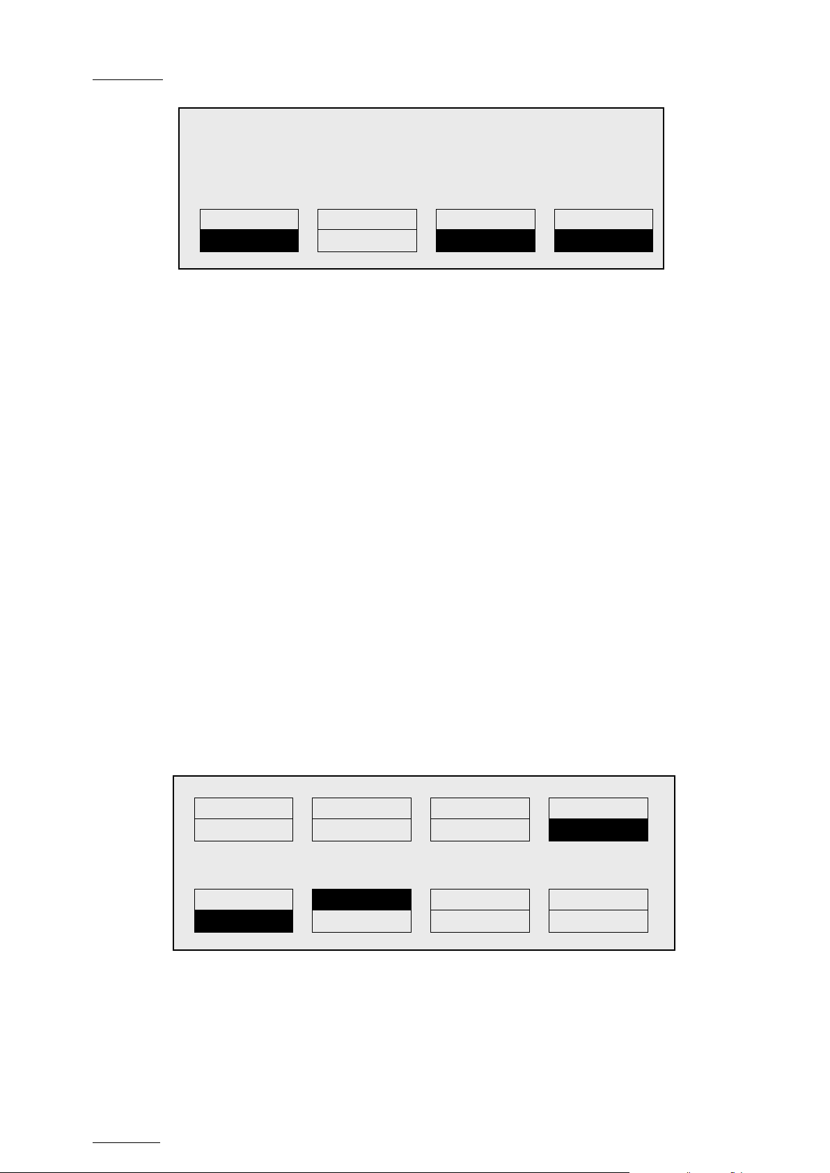
Issue
10.04.A
EVS Multicam Vers ion 10.04 – Operating Manual
46
Copy Clip 113 to Clip 141
COPY
MOVE
SHORT
CLIP
PGM1 112A *PRV1* 112B
Push
Aux Clip
Sort->TC
Post-Roll
>Archive
***
Name
Cam
Rst Cam
Local
Sync Prv
2nd CTRL
Cam A
Cam B
Cam C
Cam D
EVS Broadcast Equipment SA – January 2011
Cam A B
[Menu]: Cancel
[Enter]: Confirm
4. Select the COPY or MOVE f unct ion by pressing the A or B key.
The corresponding function will be highlighted on the LCD and the message
on the OSD will be upd ated accordingly.
5. Select the CLIP or CAM mode with the D key.
6. Select the SHORT or LONG mode with the C key.
7. Press ENTER to confirm or MENU to cancel.
When doing a network copy, the VGA displays the % copied of each clip.
HOW TO CANCEL A NETWORK COPY ON THE REMOTE PANEL
When the clip is copying, its light flashes green. Pressing CLEAR + the
corresponding F_ key allows cancelling the network copy. A confirmation screen
comes up to cancel the network copy: “Cancel network copy ? MENU: Do not
cancel copy - ENTER: Cancel copy”
9.2.8 SECONDARY MENU IN CLIP MODE
OVERVIEW
In Clip mode, the secondary menu of the Remote Panel is different from the
Record Train mode:
P.1 B.1 Clips: Local Records: Local
PL 11: < >
Msg:
P
Page 57
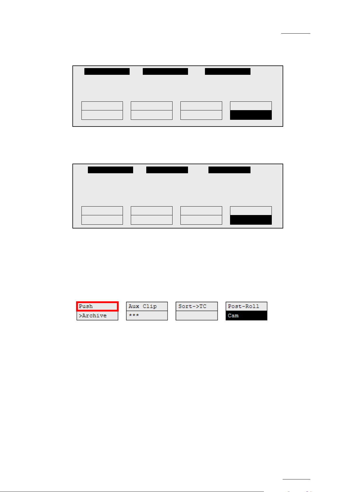
EVS Mult icam Version 10.04 – Operat ing Manual
EVS Broadcast Equipment SA – January 2011
Issue
10.04.A
47
1keyword890123 2 keyword89012 3 keyword89012
Push
Aux Clip
Sort->TC
Post-Roll
>Archive
***
Cam
1 keyword890123 2 keyword89012 3 keyword89012
Push
Aux Clip
Sort->TC
Post-Roll
>Archive
***
Name
Cam
Press MENU to access the secondary menu. If no keyword file is selected in the
setup, the LCD display will be:
111A
In this mode of the secondary menu, clips can still be directly recalled using the
F1-F10 keys of the Remote Panel.
If a keyword file is selected in the setup, the LCD display will be:
F1:action_1 F6:action_6
F2:action_2 F7:action_7 111A
F3:action_3 F8:action_8
F4:action_4 F9: p.01
F5:action_5 F0:Next page
In this mode of the secondary menu, the F1-F10 keys are used for keyword
assignment, and thus can no longer be used to recall clips. For a description of
the keyword-related functions, please refer to the “Keyword Management” Section
of this m anual.
The ID of the current clip appears on t he end of line 3 of the LCD display.
PUSH
Introduction
The Push function allows you to easily send a copy of a clip to another machine
on the network, either via the GigE network or the SDTI network.
Principle
•
If one or two d efault targets (push machines) ar e defined in the s etup, the clip
will be automatically sent to these machines.
• If no default target is defined, the list of machines available on the network
will appear. As soon as the operator selects one of them, the clip is pushed.
Depending on the push settings defined, the default targets or the list of
possible targets submitted to you will contain EVS servers on the SDTI
network and/or EVS servers on the GigE network.
For more information about the Push settings, refer to the Remote Panel
setup, page 3.3.
Page 58

Issue
10.04.A
EVS Multicam Vers ion 10.04 – Operating Manual
48
EVS Broadcast Equipment SA – January 2011
In both cases, a message appears for a few seconds on the LCD to confirm that
the clip is being pushed and indicating the clip location where it will be stored on
the receiving machine.
If the Receive Page(s) defined on the destination machine is (are) full, the
operator who tries pushing the clip is notified. While this message is being
displayed, the operator can press the MENU key at any time to return to the
normal menu. Depending on the CAM/CLIP mode selected by the D key, only the
camera angles loaded on the controlled channels are pushed (CAM mode), or all
camera angles of the clip are pushed at onc e (CLIP mode).
>ARCHIVE
The Archive function allows the operator to flag a clip to place it in the archive
queue of the XFile
This function is blinking when the clip is flagged for archiving, but has not yet
been archived. It is permanently highlighted when the archiving of the clip is
completed.
1
defined in the Setup menu (p.3.3 F3).
Depending on the mode selected with the D key (CLIP/CAM), the >ARCHIVE flag
is assigned only to the camera angles of the clip loaded on the controlled
channels (CAM mode), or to all c amera angles of the c lip ( CLIP mode).
AUX CLIP
This function allows assigning a clip as auxiliary audio clip to the current playlist.
Press CLEAR + Aux Clip (CLEAR + SHIFT + B) to remove the current auxiliary
clip. Refer t o the Chapter 11 ‘Playlist Management’, on page 89 f or more details.
RANKING (***)
The Ranking function allows assigning a ranking to the current clip. Pressing
several times this key will scroll through the different values: 0 (***, not
highlighted).
Depending on the mode selected with the D key (CLIP/CAM), this ranking is
assigned only to the camera angles of the clip loaded on the controlled channels
(CAM mode), or to all camera angles of the clip (CLIP mode).
If the Keyword Info parameter of the Setup menu is set to “Yes”, the ranking will
appear on the OSD of the output monitors when cueing up the clip.
1
The EVS X file is a 2U device with 2 rem ovable hard drives, that can be c onnec ted to t he XNet SDTI network. Clips
can be archi v ed to/restored from t he removable medias.
Page 59
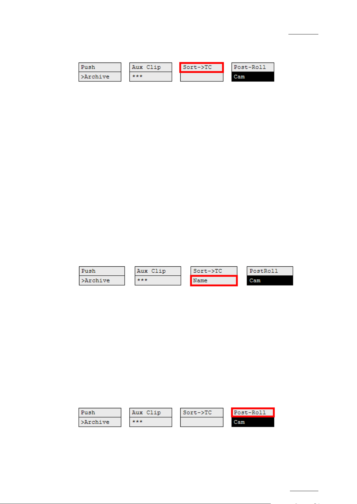
EVS Mult icam Version 10.04 – Operat ing Manual
EVS Broadcast Equipment SA – January 2011
Issue
10.04.A
49
SORT->TC
The Sort->TC function allows the operator to search the database for all clips or
trains containing a s pecific timecode. Press SHIFT+C again in Set TC mode to call
it.
When calling this f unction, the timecode of the current picture is used as a d efault
selection. The operator can immediately perform the search or he can edit that
timecode before starting the searc h.
For more information on how to search for clips by timecode, refer to the section
9.2.9 ‘H ow t o S earch for Clips by Timecode’, on pag e 50.
SET TC
The Set TC function is only ava ilable in SHIFT+B on the S ort->TC menu. It allows
the operator to restr ipe t he timecode of a clip. This f unc tion is explained in details
in the Section 9.3.12 ‘How to Restripe the Timecode of the Current Clip’, on page
62.
Depending on the mode selected with the D key (CLIP/CAM), the new timecode
value is assigned only to the camera angle of the clip loaded on the primary
channel (CAM mode), or to all cam era angles of the clip (CLIP mode).
NAME
The Name function is only available if a keyword file is selected in the Setup
menu. It is used t o name a clip based on available keyword s. Refer to the Chapter
10 ‘Keyword Management’, on page 72 for more details. When the Name function
is selected, pressing SHIFT+C again will call t he Search function.
SEARCH
The Search function is “hidden” behind the Name function. Press SHIFT+C again
in Name mode to call it. It allows the operator to search the database for clips
based on keywords and ranking. Please refer to Chapter 10 ‘Keyword
Management’, on page 72 f or d et ai ls.
POST-ROLL
enables/disables the Post-Roll mode. This mode is explained in details in the
section ‘PostRoll’, on page 28.
This function
Page 60

Issue
10.04.A
EVS Multicam Vers ion 10.04 – Operating Manual
50
The Reset function resets all default parameters, including the ones
Sort TC xx:xx:xx:xx
Reset
Set TC
From Date
To Date
Return
Clip
LTC
Srch Net
CLIP/CAM
Pressing the D key will toggle between CAM and CLIP modes on the remote.
Please note that this mode on the remote and on the VGA screens is never
synchronized. In CAM mode, the Push, Archive, Ranking assignment, Keyword
assignment, and Name functions will apply only to the camera angles of the clip
loaded on the controlled channels. In CLIP mode, these functions will apply on all
camera angles of the clip.
9.2.9 HOW TO SEARCH FOR CLIPS BY TIMECODE
Note
related to the material and the TC type t o search on.
EVS Broadcast Equipment SA – January 2011
PROCEDURE
To s earch for clips or trains containing a specific TC, proceed as follow s:
1.
From the main Remote screen in Clip mode or Train mode, press MENU to
access t he secondary menu.
2. Press SHIFT+C to access the Sort TC function.
The following screen is d isplay ed:
[Menu] : Cancel
[Enter] : Search
3.
If requested, press SHIFT+C to define a date from which the search should
be applied:
a. Type the date in dd/mm/yy format with the F1 to F10 keys.
b. Press ENTER to confirm and exit the field.
4.
If requested, press SHIFT+D to d efine a d ate to which the search should be
applied:
1. Type the date in dd/mm/ yy format with the F1 to F10 keys.
2. Press ENTER to confirm and exit the field .
5.
Press the B key to specify whether to search for clips (Clip), train (Rec) or
both (Clip+Rec).
Press several times the B key to select the requested value.
Page 61

EVS Mult icam Version 10.04 – Operat ing Manual
EVS Broadcast Equipment SA – January 2011
Issue
10.04.A
51
key to mark a new Short OUT point. The new Short OUT
6.
Press the C key to specify whether to search for the LTC (LTC), the userdefined timecode type (USER) or whatever TC type (LTC+USER).
Press several times the C soft key to select the requested value.
7.
Press the D key to specify whether to search only for local clips (Srch Loc)
or on the entire XNet Network (Sr ch Net ).
Press several times the D key to select the requested value.
8. Press ENTER to launch the search.
RESULTS
If matching clips are found, the Remote Panel will automatically be in Browse
mode (the BROWSE key is red), allowing the oper ator to quickly view the frame of
each clip corresponding to the requested timecode by rotating the jog dial.
To be able to jog inside a clip, disable the Browse mode by pressing on the
BROWSE key and move the jog dial. To return to the Browse mode inside the
search results, press the BROWSE key again.
Search results are reset when going by to LIVE mode, or when a new search is
performed.
EXAMPLES
• You have loaded the picture of an interesting event, and you want to see all
clips that contain that same event. Call the Sort ->TC function, select the
network/local search option and launch the search. Move the jog dial and you
will see the same event on the same timecode from all available camera
angles that have been clipped.
• You know the timecode of a particular event and you want to see all clips
containing that event. Call the Sort ->TC function, edit the timecode to the
desired value, select the network/local search option and press ENTER: you
will obtain the same result as above if the timecode belongs to the same type
as the one previously mentioned .
9.2.10 HOW TO SHORTEN A CLIP
To shorten a clip, proceed as follows:
1. Recall the desired clip by pressing the corresponding F_ key.
2. Move the jog dial to browse the clip and reach to the desired Short IN point.
3.
Press the IN key to mark a new Short IN point. The new Short IN point is
instantly saved.
4. Move the jog dial to reach the desired Short OUT point.
5.
Press the OUT
point is instantly saved.
Page 62

Issue
10.04.A
EVS Multicam Vers ion 10.04 – Operating Manual
52
Move the lever or press the PLAY key to play the clip. The replay will stop at the
new Short OUT point (or after the Short OUT point if the Post-Roll mode is
enabled).
GOTO IN and GOT O OUT
You can use Goto IN and Goto OUT functions to jump immediately onto Short IN
or Short OUT points respectively.
9.2.11 RESTRIPING THE TI MECODE O F A CLIP
RESTRICT IONS ON THE REMOTE PANEL
The function to restripe the timecode of a clip via the Remote Panel is more
restricted than via Multicam on the VGA:
• You cannot choose which timecode type you modify: you will automatically
modify the primary timecode of the clip.
• You cannot modify the date of the clip.
EVS Broadcast Equipment SA – January 2011
• You cannot modify the type for the primary t imecod e of t he cli p.
If you want to modify the date, the type of the primary timecode or the userdefined timecode, you need to go to the Set Timecode screen in the VGA. For
more inform at ion, refer to the section 9.3.12 ‘How to Restripe the T imecode of the
Current Clip’, on page 62.
HOW TO RESTRIPE THE TIMECODE OF A CLIP
To restripe the timecode of a clip on t he Remote Panel, proceed as follows:
1. Recall the clip by pressing the corresponding F_ key.
2.
Move the jog dial to reach the picture where you want to define a new
timecode.
3. Press the MENU key to access the secondary menu.
4. Press SHIFT+C to call the Set TC function.
5. Enter the new timecode for the current picture.
6.
In 59.94Hz modes (NTSC), you can select between Drop Frame and Non
Drop Frame modes by pressing SHIFT+MENU.
7. Press the D key to select CAM or CLIP mode.
• In CAM mode, only the timecode of the camera angle loaded on the
primary channel will be changed.
In CLIP mode, the timecode of all camera angles of the clip will be
changed.
8.
Press ENTER to confirm or MENU to cancel.
The primary timecode of the entire clip is updated according to the new timecode
Page 63

EVS Mult icam Version 10.04 – Operat ing Manual
EVS Broadcast Equipment SA – January 2011
Issue
10.04.A
53
value so that the timecode remains continuous inside the whole clip. The next time
this function is called the value previously used will be set as default.
9.2.14 HOW TO SAVE ALL CLIPS/PLAYLISTS
1. Go to t he Main menu (SHIFT + MENU)
2. Press the function key F0 on the remote to save clips and playlists.
9.3 USING THE CLIP SCREEN
The VGA Clip screen is accessed by selecting the F9 key on the keyboard. With
this screen, clips can be recalled using the pen and tablet or directly from the
keyboard.
Important
The action performed on a channel from the Clip screen is concurrent to
any other controller that might be assig ned to that channel: EVS Remote
Panel or external protocol. A command sent from the Clip screen to a
channel will overwrite whatever the channel was doing at that time.
9.3.1 CLIP SCREEN – STANDARD VIEW
The navigation through t he Clip screen, and the various functions availab le on this
screen, can be performed using the tablet and stylus , or the keyboard shortcuts.
Page 64
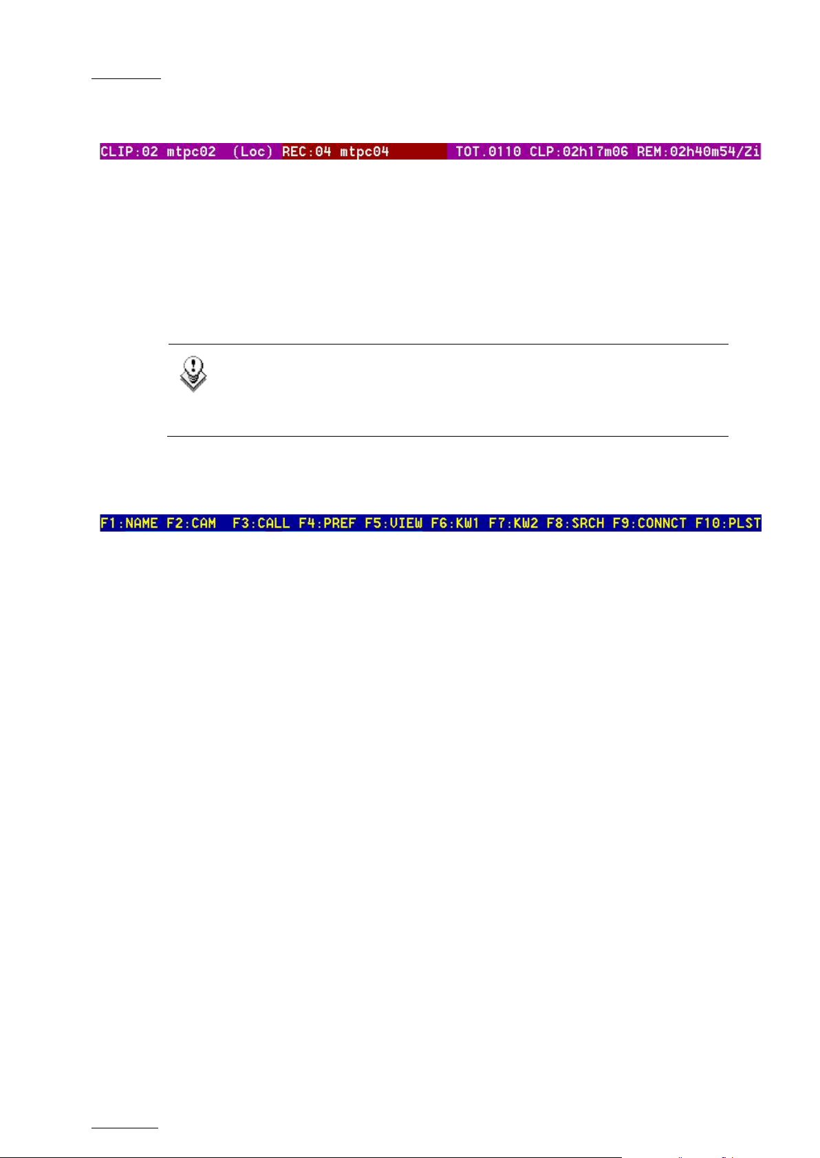
Issue
10.04.A
EVS Multicam Vers ion 10.04 – Operating Manual
54
The abbreviated word “(Loc.)” appears next to the name if the local
9.3.2 THE TITLE BAR
The Tit le bar contains the s tatus information:
• Number and name of the server currently selected for clips and for record
trains (*). T he name is blinking red if it is a network machine.
• Total number of clips (i.e. protects, 1 camera angle counting for 1 clip in this
count)
• Total duration of all clips
• Remaining capacity on the server (all record trains together; valid for local
server only)
Note
machine is currently selected for clips and/or for record trains. The clips
displayed in the clip screen belong to this machine.
EVS Broadcast Equipment SA – January 2011
9.3.3 THE FUNCTION BAR
The second line displays the available functions. Each function can be called by
the corresponding F_ key of the keyboard, or by clicking with stylus & tablet on
the corresponding area on this line.
F1 : Nam e
This function is used to name a clip. For more information on how to name a clip
in the V GA, refer to the s ection 9.3.8 ‘How to Name a Clip’, on page 60.
F2 : Clip /Ca m
This function toggles between CLIP mode and CAM mode.
• In CLIP mode, actions on a clip will use all available cameras for this clip.
• In CAM mode, actions on a clip will only use the selected camera for this clip.
Other functions such as Name, Delete, Copy, Set TC, >Archive depend on this
mode selection.
F3 : Call
The operator can gain immediate acces s to a local or network clip b y typing its ID
number.
Page 65

EVS Mult icam Version 10.04 – Operat ing Manual
EVS Broadcast Equipment SA – January 2011
Issue
10.04.A
55
F4: Pref
This option changes the primary camera of a clip. For information on how to
change the primary cam era of a clip, refer to the section 9.3.9 ‘How to Change the
Primary Camera of a Clip’, on page 60.
F5 : Vi ew
This option changes the standard display to the extended display and vice versa.
Refer to t he section 9.3.14 ‘Clip Screen – E xte nded Vie w’, on page 65.
F6 : KW1
This option calls the On-Air Keyword screen. Refer to the Chapter 10 ‘Keyword
Management’, on page 72 f or mor e d et ai ls.
F7 : KW2
This option calls the Off-Air Keyword Screen. Refer to the Chapter 10 ‘Keyword
Management’, on page 72 f or mor e d et ai ls.
SHIFT+F7:Delay
This function calls the Video Delay VGA screen. Refer to the Chapter 8 ‘Video
Delay’, on page 36.
F8: Search
This option calls the VGA Search Screen. Refer to the Chapter 10 ‘Keyword
Management’, on page 72 f or mor e d et ai ls.
SHIFT+F8:Net
This option switches to the Network Status Screen and allows monitoring the
status of the different machines c onnected on the network.
Page 66
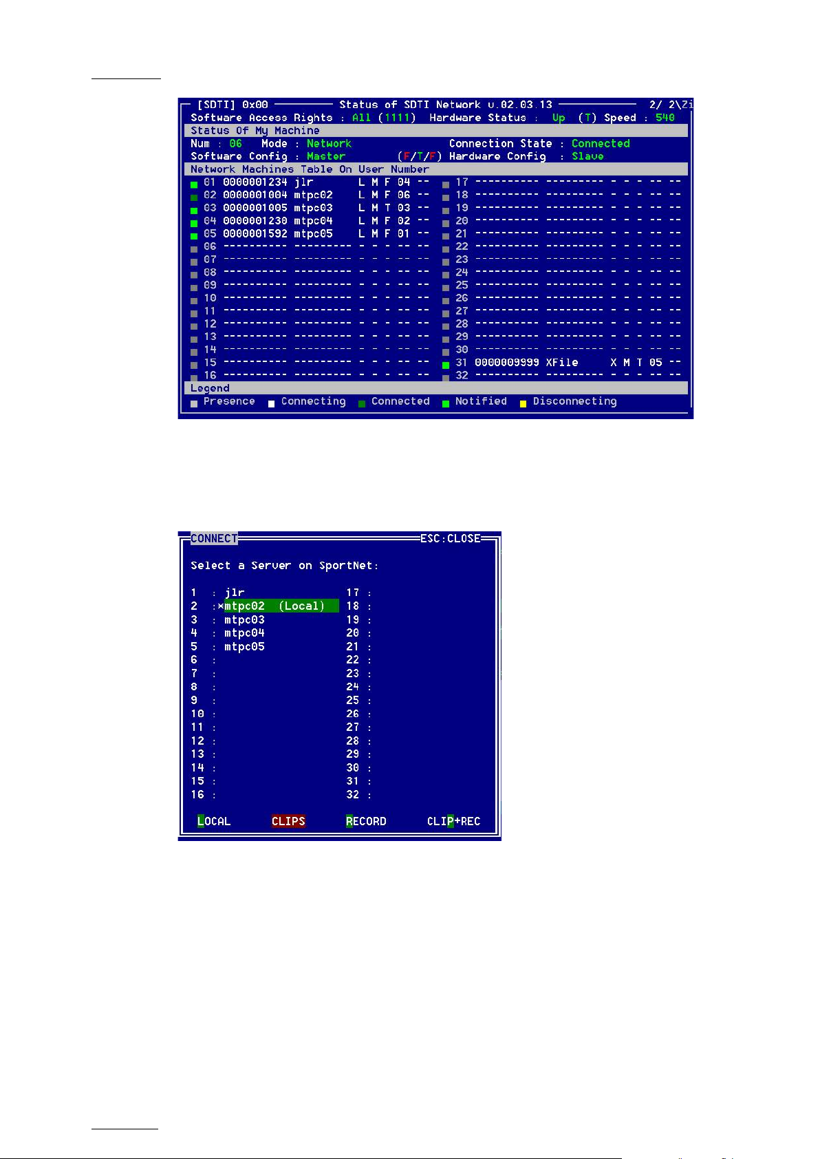
Issue
10.04.A
EVS Multicam Vers ion 10.04 – Operating Manual
56
EVS Broadcast Equipment SA – January 2011
F9:Connect
This option calls the CONNECT window. This window allows the operator to
connect to the clips and record trains of other machine on the network.
The following functions can be used in the CONNECT window:
ALT+L: return to LOCAL mode and close the CONNECT window
ALT+C: CLIP S m ode - to connect to the clips of a r emote machine
ALT+R: RECORD mode - to connect to the record t rains of a remote machine
ALT+P: CLIP+REC mode - to connect to the clips and record trains of a remote
machine.
After selecting CLIP, RECORD or CLIP+REC mode either with the keyboard or by
clicking with t he stylus , select the machine you want to connec t to: click on it with
the stylus, or move with the arrow keys and pr ess ENTER on the keyboard.
Page 67
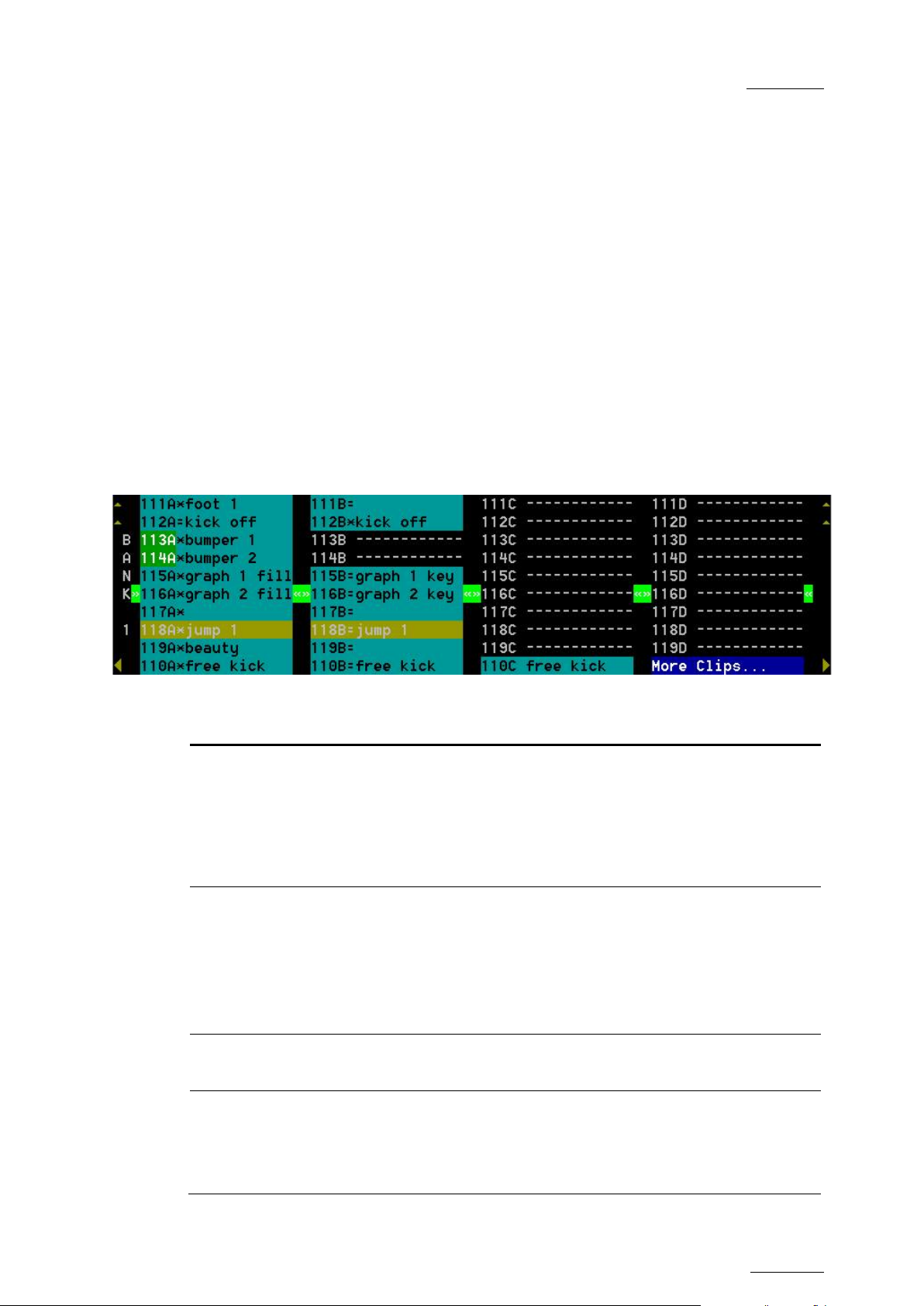
EVS Mult icam Version 10.04 – Operat ing Manual
EVS Broadcast Equipment SA – January 2011
Issue
10.04.A
57
The clip rank information is highlighted in blue if the clip is
Pressing ALT+L or clicking with the stylus on “LOCAL” will close the CONNECT
window and return to local clips and record trains.
To close the CONNECT window without changing the connection mode or remote
machine, press ESC.
The “*” next to one of the machine in the list indicates which machine is the
active network server. Refer to the Chapter 13 ‘Operating on XNet Network’, on
page 150 for d etails.
F0:Playlist
The Playlist screen can be accessed by selecting F10 on the keyboard.
9.3.4 THE CLIP INFORMATION AREA
The next ar ea is the Clip Information Area which d isplays the clips of the selected
page and bank(s). Two clips’ banks are displayed at a time.
For each clip and camera angle, the following information is available:
Field Description
Cli p ID Unique identifier of the clip on t he s erver. Ex: 111A
Clip “rank” Clip rank depending on the channel on which it has been created :
The clip ID is followed by the “Creating” message when the clip is
in the process of being created, copied or moved to this location.
For more information on growing clips, refer to the section 9.2.5
‘Recall and Playback of Growing Clips’, on page 42.
• Primary (“*” next to the clip ID)
• Second ary (“=” next to the clip ID)
protected.
Clip name
Archive
Status
Name of the clip, either automatically assigned or defined by the
user.
• if the c lip ID is b linking g reen, the clip is flagged for archiving,
but not yet archived
• if the c lip ID is permanently high lighted in g reen, the archiving
of the clip has been completed.
Page 68
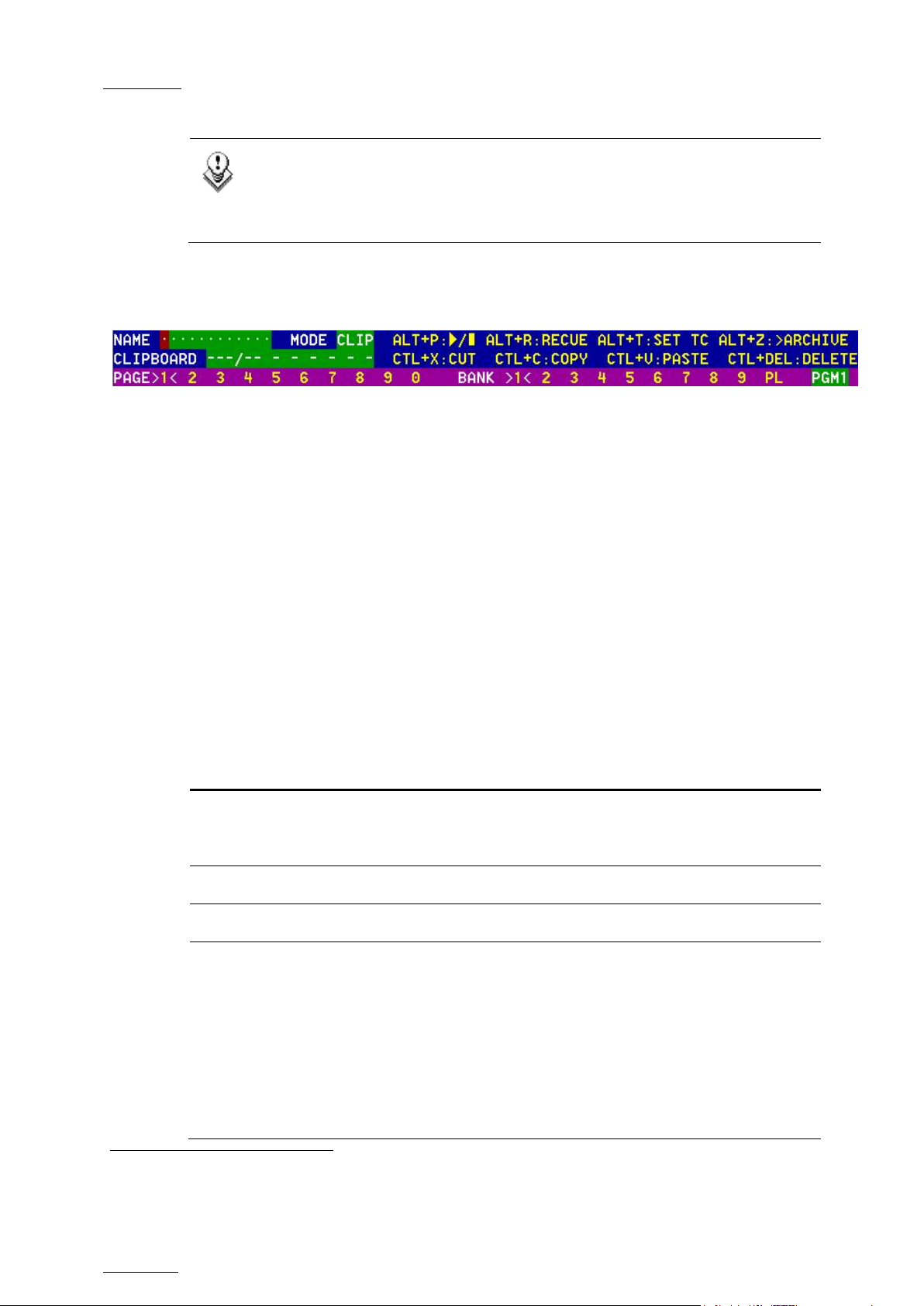
Issue
10.04.A
EVS Multicam Vers ion 10.04 – Operating Manual
58
(CLIP/CAM), the >ARCHIVE flag is assigned only to the
Note
In the standard view (cameras A to D), if camera E and/or F exist for a
particular clip, the D-column for this clip is replaced by the mention
“More Clips” on blue backg round.
9.3.5 THE CLIP MANAGEMENT AREA
NAME CAPTURE FIELD
This is the only capture area of the screen. It is used to enter the name to assign
to a clip/playlist, or to enter the ID of a clip to recall.
EVS Broadcast Equipment SA – January 2011
MODE FIELD
It indicates if the clip screen is currently in CLIP or CAM mode. In CLIP mode,
actions on a clip wi ll use a ll a vailable cameras for t his clip. In CAM mode, actions
on a clip will only use the selected camera for this clip. Default value is CAM
mode.
CLIP CONTROL AREA
It is d ed ic ated t o pla y-out control.
Command Description
ALT+P:►/■
ALT+R:RECUE Jumps to t he Short IN point.
ALT+T: SET TC Restripes the timecode of the current clip.
ALT+Z:>ARCHIVE
Plays at 100% speed except for super motion clips which
are played back at 33% s peed; and pause playback on the
current picture.
Allows the operator to flag a clip to place it in the archive
queue of the XFile
or in t he Setup screen.
1
defined in the Setup menu (p.3.3 F1)
When a clip is flagged for archiving, but has not yet been
archived, its ID will be blinking green in the Clip screen. It
is permanently highlight ed green when the ar chiving of t he
clip is completed.
Depending on the mode selected with the F2 key
1
The EVS X file is a 2U device with 2 rem ovable hard drives, that can be c onnec ted to t he XNet SDTI network. Clips
can be archi v ed to/restored from t he removable media.
Page 69

EVS Mult icam Version 10.04 – Operat ing Manual
EVS Broadcast Equipment SA – January 2011
Issue
10.04.A
59
camera angle of the clip selected with the green cursor
perator to select on which
browse clips on a play channel not used by the main
Command Description
(CAM mode), or to all camera angles of the clip (CLIP
mode).
PG M X
Located in the bottom right corner of the clip screen, this
field is only visible if the Call Channel VGA function has
been enabled in the Setup Menu (p. 3.1 – F5) or in the
Setup Screen, and is only effective in CAM mode, not in
CLIP mode. It allows the o
channel clips called using the keyboard/tablet and VGA
should be loaded.
Press ALT + F1 on the keyboard to select PGM1, ALT +
F2 for PGM2/PRV, ALT + F3 for PGM3, etc. This function
is useful to load clips on channels that cannot be
controlled by an EVS Remote Panel, or to allow an AP to
operator. Note that if that channel is in PLST EDIT mode
with a PRV, the clip will aut omatically cue up on t he PRV.
9.3.6 SELECTING A CLIP WITH TABLET AND STYLUS
To select a d if ferent page or bank using the stylus, click on the d esired page/bank
number on the bottom line of the screen. You can also move to the adjacent
page/bank by clicking on the red arrows on the top, bottom and sides of the
screen:
• left/right arrow: go to previous/next page
• up/down arrow: go to previous/next bank
If a clip is present in a certain location, it will be highlighted in BLUE. Once
selected, it will be highlighted in ORANGE.
To cue up a clip on the primary channel controlled by the first remote, or on the
VGA Call Channel defined in the setup, simply click
1
on it with the stylus. If the
channel where the clip is supposed to be loaded is in Pl st Edit mode with a PRV
channel attached, the clip will automatic ally cue up on the PRV channel.
9.3.7 SELECTING A CLIP WITH TH E KEYBOARD
The keyboard c an also be used to oper ate within the c lip screen. The g reen arrows
surrounding a clip shows the current cursor position. The arrow keys (
on the keyboard are us ed to move across t he screen. Only 2 banks c an be viewed
at a tim e.
To view other banks, use ALT + ↑,↓ to scroll vertically between banks and use
ALT +
←,→ or Pg Dn, Pg Up to scroll horizontally between pag es. To go to bank 1
of the current page, use the HOME key and to go to the Playlist bank of the
current page, use the END key
2
.
1
“Clicking with the s tylus” means pres s ing lightly the t ip of the stylus onto t he t ablet.
2
Trying to access the playlist bank of page 10 will cause t he Clip screen t o jum p to the playlist bank of page 9, since
page 10 playlists are r es er ved for ext er nal protocols.
↑,↓,←,→)
Page 70

Issue
10.04.A
EVS Multicam Vers ion 10.04 – Operating Manual
60
Clip Edit by
If the selected camera is a secondary camera (indicated by “=”), it
Once the cursor located on the desired clip, press ENTER to cue up the clip on
the primary channel controlled by the first remote, or on the VGA Call Channel
defined in the setup. If the channel where the clip is supposed to be loaded is in
Plst Edit mode with a PRV c hannel attached, the clip will aut omatically cue up on
the PRV channel.
If the Clip screen is connected to the clips and playlists of a remote machine,
pressing ALT+L will r eturn the scr een immediately to the local c li ps and playlist s.
9.3.8 HOW TO NAME A CLIP
1. In the Clip screen, select the clip t o name in one of the following ways:
• Click on the clip with the stylus
• Positioning t he green arrows around the des ired clip with the keyboard .
2.
Type in the desired name with the keyboard. All characters available from
the keyboard are accepted, including blanks.
3. Press F1:
EVS Broadcast Equipment SA – January 2011
• In CAM mode, only the camera where the cursor is locat ed is named.
• In CLIP mode, all cameras of the clip where the cursor is located are
named.
The entry in the Name field is not cleared by pressing F1 and remains for future
use. Press <BACKSPACE> to delete the last character in the Nam e field, or press
ESC to clear the whole field.
Note
To be able to name/rename clips on a network machine, the
Network setting in the setup of the remote machine must be set to “Yes”
(VGA Setup screen) or “Enabled” (Setup menu on the Remote Panel). If
you are unable to name a network clip, please check this setting on the
remote mac hine.
9.3.9 HOW TO CHANGE THE PRIMARY CAMERA OF A CLIP
1. In the Clip screen, move the cursor to t he desired camera.
2.
Press F4 on the keyboard or click with the stylus on the corresponding area
in the Function bar.
→ This camera becomes the new primary camera.
→
becomes the primary camera and the previous primary camera becomes the
secondar y camera.
Page 71

EVS Mult icam Version 10.04 – Operat ing Manual
EVS Broadcast Equipment SA – January 2011
Issue
10.04.A
61
9.3.10 RECALLING A CLIP
HOW TO CALL A CLIP BELONGING TO THE MACHINE YOU ARE CONNECTE D TO
The machine to which you are connected is indicated on the left side of the Title
Bar.
To call a clip belonging to the machine you are connected to, proceed as follows:
1. Type either the 3 or 4 digits of the ID. Ex: 111 or 111A. The entry appears in
the Name field.
2. Press F3
o If only 3 digits are entered, the primary camera is selected
o If 4 digits are entered, the clip is selected according to the given camera
angle.
o If no clip matches the entry, no selection is d one.
Note
ESC key can still be used at any time to clear the Name f ield .
HOW TO CALL A CLIP BELONGING TO ANOTHER MACHINE THAN THE ONE Y OU ARE CONNECTED T O
1. Type either the first 3 or 4 digits of the ID, followed by a “/” and the network
number of the machine. Ex: 111/03 or 111A/03. To call a local clip, no matter
what machine you are connect ed to, type 00 as network num ber. Ex: 111/00 or
111A/00.
2. Press F3.
9.3.11 HOW TO CANCEL A NETWORK COPY ON THE VGA
Select the clip and press the CTRL+DELETE keys. A confirmation screen comes
up. “Cancel network copy? ESC: Do not cancel copy - ENTER: Cancel copy”
If the Copy Clip option copies several cams of the same clip and some of them
have already been copied before the Cancel function, the cancel does not do a
delete of the copied files, it just cancels the cam(s) still copying or to be copied of
that clip. It does not cancel the copying of other clips.
The Cancel function remains possible even if the page where the clip is being
copied is protected.
Page 72
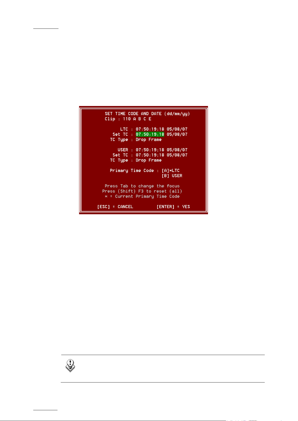
Issue
10.04.A
EVS Multicam Vers ion 10.04 – Operating Manual
62
EVS Broadcast Equipment SA – January 2011
9.3.12 HOW TO RESTRIPE THE TIMECODE OF THE CURRENT CLIP
To restripe the timecode of the current clip, proceed as follows:
1.
Recall the clip by moving the cursor on the desired clip and pressing
ENTER, or by clicking on it with the stylus.
2. Press ALT-T on the keyboard to call the S ET T C function.
The Set Timecode screen is displayed (without TC Type field with PAL –
refer to note below):
3.
If you want to modify the LTC timecode and date, type in the new timecode
for the Short IN point and date of the clip in the Set T C field below the LTC
field.
4.
If you want to modify the user-defined timecode and date, type in the new
timecode for the Short IN point and date of the clip in the Se t TC field below
the USER field.
5.
If you want to m odify the prim ary TC for this c lip, press the A or B key which
corresponds t o the requested prim ary TC.
6. Press F2 to select CAM or CLIP mode
• In CAM mode, only the timecode of the camera angle loaded on the
primary channel will be changed.
• In CLIP mode, the timecode of all camera angles of the clip will be
changed.
7. Press ENTER to confirm or ESC to cancel.
The entire clip is updated according to the new timecode value so that the
timecode rem ains continuous insid e the whole clip.
Note
In 59.94Hz modes (NTSC), you can also select between DROP FRAME
and NON DROP FRAME modes by pressing the space bar.
Page 73

EVS Mult icam Version 10.04 – Operat ing Manual
EVS Broadcast Equipment SA – January 2011
Issue
10.04.A
63
9.3.13 MOVING AND COPYING CLIPS
Copying and moving clips in the VGA are performed using the CUT, COPY and
PASTE functions .
GENERAL PRINCIPLES
• If the clipboard was filled using the Cut function, the original clip(s) is/are
deleted after being pasted to the new location.
• In CAM mode, only the selected camera of the clip is Cut/Copied/Pasted. In
CLIP mode, all camera angles of the clip are Cut/Copied.
• For the Paste function in CLIP mode, only the available camera locations
inside the destination clip will be pasted. If some camera angles already exist
for the destination clip, these will not be overwritten by the corresponding
camera in the clipboard.
• A “Cut & Paste” of a clip is equivalent to a “Move Clip”, meaning that any
reference to that clip inside playlists will be updated to the new location of
that clip. This is not the case when doing a “Copy & Paste”, then deleting
manually the original clip.
CLIPBOARD FIELD
This area displays the content of the clipboard: clip number, network number if the
copied clip/playlist is a remote clip/playlist, and the selected camera(s) for a clip.
The rest of the line summarize the available functions (copy, cut, paste, delete)
and their keyboard shortcuts. These functions can also be called by clicking on
the corresponding area on this line.
CTL+ X: CUT
This command is only applicable to clips.
1. Move the cursor to the clip to “cut” from the Clip screen
2. Press CTRL + X on the keyboard or click on the corresponding area on the
screen.
The clip removed from the current location and copied to the clipboard.
CTL+C: COPY
1. Move the cursor to the clip/playlist to copy
2. Press CTRL + C on the keyboard or click on the corresponding area on the
screen.
The clip is copied to the clipboard.
Page 74

Issue
10.04.A
EVS Multicam Vers ion 10.04 – Operating Manual
64
EVS Broadcast Equipment SA – January 2011
CTL+V: PASTE (LONG COPY)
With the Long copy, the entire original clip is copied, including its guardbands, to
the destinat ion.
1. Move the cursor to the clip/pla ylist location where the content of the clipboard
should be copied.
2. Press CTRL + V or click to t he corresponding area on the screen.
The clip in the clipboard is copied to the selected location in Long mode.
CTL+SHIFT+V: PASTE (SHORT COPY)
With the Short copy, the material between the Short IN and Short OUT points of
the original clip is copied, augmented by the duration of the default guardbands.
This allows saving space on the EVS server.
1. Move the cursor to the clip/pla ylist location where the content of the clipboard
should be copied.
2. Press CTRL + SHIF T + V.
The clip in the clipboard is copied to the selected location in Short mode.
CTL+DEL:DELETE
1. Move the cursor to the clip/playlist to delete.
2. Press CTRL + DEL or c lick on the corresponding area on the clip screen.
→ In CAM mode, only the camera selected is deleted
→ In CLIP mode, all cameras of the clip are deleted .
Important
A clip/playlist cannot be deleted while it is on air.
Note
• When a clip is deleted, all playlists are scanned and that clip is
removed from all of them.
• When a clip is protected, or when the “Confirm Delete Clip” is set to
“Yes” in the setup menu (p.3.1 F2), a confirmation is required to
delete the selected clip(s).
Page 75
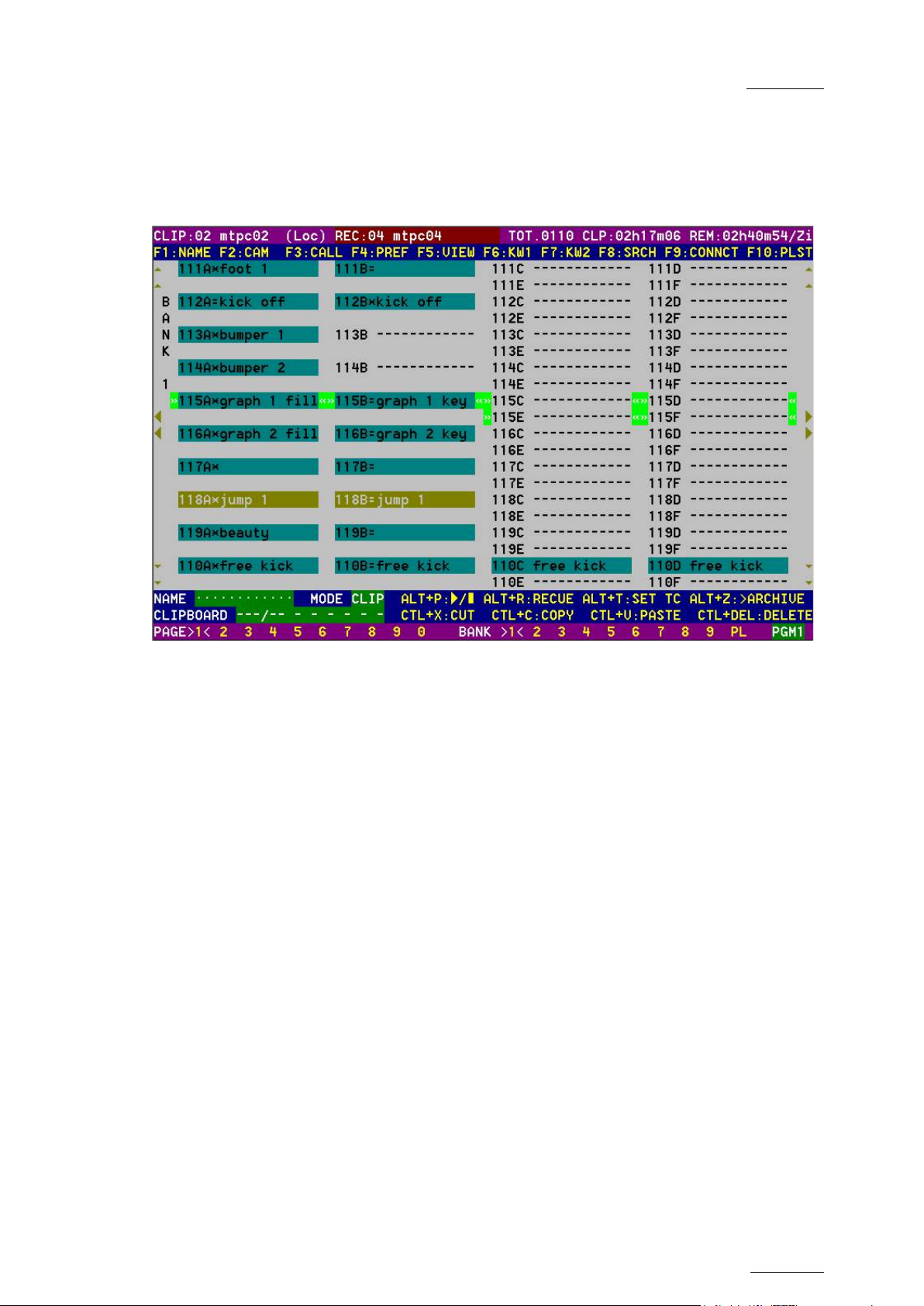
EVS Mult icam Version 10.04 – Operat ing Manual
EVS Broadcast Equipment SA – January 2011
Issue
10.04.A
65
9.3.14 CLIP SCREEN – EXTENDED VIEW
The extended view shows cameras A to F instead of A to D. Only 1 bank can be
viewed at a time. The switch between standard and extended view is done by
pressing F5 on the keyboard or by clic king on the “F5:VIEW” area on the screen.
Page 76

Issue
10.04.A
EVS Multicam Vers ion 10.04 – Operating Manual
66
9.4 USING THE VDR PANEL
The VGA VDR Panel is accessed from any VGA screen by pressing SHIFT+F9 on
the keyboard. The lower section of the VDR Panel is similar to the clip screen,
with the same functions. The upper section of the VDR Panel features 2 windows
that can each take control of one channel of the server.
Pressing SHIFT+F9 in the VDR Panel r eturns t he VGA to the Clip screen mode.
EVS Broadcast Equipment SA – January 2011
9.4.1 VDR PANEL – LOWER SECTION
The browsing of clips, the viewing modes (normal or extended), the way clips are
recalled, moved and copied, etc. in the VDR Panel is strictly the same as in the
Clip screen. The CONNECT window is called with F9, and allows to connect to
other servers on the network.
9.4.2 VDR PANEL – UPPER SECTION
The two windows of the upper section can be assigned to a different channel of
the server. When entering the VDR Panel for the first time after starting the
application, the control of both windows is disabled.
Press CTRL+F1 to gain control of the left window, or CTRL+F2 to gain control on
the right window. The frame around the corresponding window becomes green.
Note that only one window can be active at a time. Inside the active window,
letters/numbers highlighted in green indicate the keyboard shortcut to the
corresponding function: press ALT + the highlighted letter/number. All functions
are also available by clicking wit h t he stylus.
Page 77

EVS Mult icam Version 10.04 – Operat ing Manual
EVS Broadcast Equipment SA – January 2011
Issue
10.04.A
67
ID of the curr ent element
Current t im ec ode
Name of the
List of available camera
The name of the channel currently assigned to each window is displayed on the
top of each of them. To ass ig n a new channel to this window, press ALT+H. A new
window appears on the other side to allow the selection of a new channel.
Important
The control of a channel from the VDR Panel is concurrent to any other
controller that might be assigned to that channel: EVS Remote Panel or
external protocol. A command sent from the VDR Panel to a channel will
overwrite whatever the channel was doing at that time.
Use the ↑ /↓ arrow keys to select the channel and press ENTER, or directly press
ALT + the number of the channel as highlighted in green. The Play channels
already assigned appear in grey and cannot be selected. Select “0 – Disable
Window” if you don’t want to assign any channel to the window. Depending
whether a Play or Record channel is assigned to the VDR Panel window, its
content is automatically updated.
9.4.3 VDR PANEL – PLAYER WINDOW
(clip or train)
current element
angles (green) and
selected camera angle
(red)
HOW TO LOAD A RECORD TRAIN
Press ALT+L to g o in LIVE mode (or click on the LIVE function), then press ALT +
the letter of the desired record train (A/B/C/D/E/F), or click on it. The letters
corresponding to the available record trains are highlighted in green, and the
letter of the current record train in red.
Page 78

Issue
10.04.A
EVS Multicam Vers ion 10.04 – Operating Manual
68
EVS Broadcast Equipment SA – January 2011
HOW TO LOAD A CLIP
Use the arrow keys to move the cursor inside the lower section of the VDR Panel
to the desired clip and press ENTER, or click on the desired clip with the stylus,
or type the des ired clip ID and press F3. To select a d if ferent camera angle inside
a clip, press ALT + the letter of the desired camera (A/B/C/D/E/F), or click on it.
Available camera angles are highlighted in GREEN, the current camera angle in
red.
PLAYING/BROW SING THE CURRENT ELEMENT
Command Description
ALT+P Play from / Pause on the current picture
ALT+Y
ALT+V
< / > (without SHIFT
key):
SHIFT + < / > Move 1 second backward / forward
CT RL + < / >
ALT + < / > Got o IN / OUT
ALT + G Go to t imec od e
Play the current clip in endless loop mode. The play will
start from the current picture until the Short OUT point of
the clip, then will automatically loop back to the Short IN
point and keep playing, and s o on…
PlayVar at the speed specified in the adjacent field. To
edit the Var speed, press ALT + % (without SHIFT key),
type the desired value and press ENTER to confirm.
move 1 field backward / forward
Fast Rewind + Fast Forward. The browsing will continue
after the keys are released.
HOW TO CREATE A CLIP WITH THE VDR PANEL PLAYER
1. Load a record train on the player
2. Browse the record train to reach the desired Short IN or Short OUT point and
press ALT+I / ALT+O to mark the Short IN / Short OUT point on the current
picture. The cursor is automatically placed in the adjacent field, so that the
operator can manually enter the timecode of the desired Short IN / OUT point
if need ed
3. Repeat this operation for the complementary Short IN / Short OUT point. This
is not mandatory. If only a Short IN or a Short OUT point is marked, the
Default Clip Duration defined in the Setup menu (p.2.2 F2) will be used to
define the missing point.
1
If the operat or k nows the timecode of the IN / O UT point, he does not need to browse t o t hat picture. He can pr es s
ALT+I on any picture, then enter the timecode of the IN / O UT point and conf ir m with ENTER.
1
. P res s ENTER to confirm, or ESC to cancel.
Page 79

EVS Mult icam Version 10.04 – Operat ing Manual
EVS Broadcast Equipment SA – January 2011
Issue
10.04.A
69
Renames the clip. Type the desired name and press
field, so that the operator can manually enter the
4. Press ALT + S to save the clip. The Save as window opens, giving the
operator the oppor tunity to name / rename t he clip if need ed. Pressing ENTER
will save the c lip to the cur rent cursor location in the lower section of the VDR
Panel. When the Save as window is open, the operator still has the possibility
to browse t he d atabase, s elec t a different page and bank, and even connect to
another machine on t he network using the CONNE CT window. Pressing ALT+U
will save the clip to the first available clip loc ation
EDITING A CLIP WITH THE VDR PANEL PLAYER
After loading the desired clip, the following functions are available:
Command Description
ALT+N
1
in the current server.
ENTER to c onf irm or ESC to c ancel.
ALT+I / A LT+O
Marks a new Short IN / Short OUT point on the current
picture. The cur sor is automatically placed in the ad jacent
timecode of the desired Short IN / Short OUT point if
needed. Press ENTER to confirm, or ESC to cancel.
HOW TO MAKE A COPY OF A CLIP WITH THE VDR PANEL PLAYER
1. Load the original clip
2. Press ALT+S to save the current clip to another location. This will create a
copy of the clip.
The operator has the opportunity to rename the clip during this operation. He
can then save the clip to the current cursor location by pressing ENTER, or to
the first available clip loc ation on the current server by pressing ALT+U.
Note
The Cut / Copy / Paste functions are available at any time to move and
copy clips in the lower section of the VDR Panel, even when one of the
upper windows is active.
1
The fir s t avai lable clip locatio n is t he first one where no camera angle is already present.
Page 80
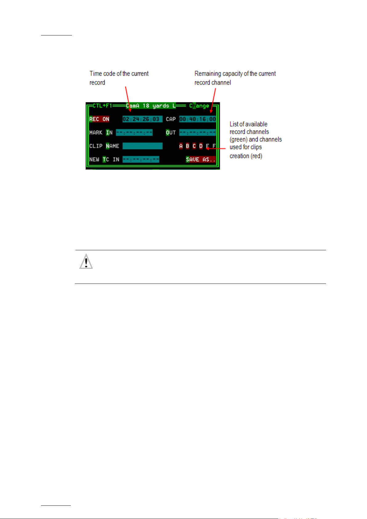
Issue
10.04.A
EVS Multicam Vers ion 10.04 – Operating Manual
70
In LSM mode, all recorders will be stopped at once to keep the
9.4.4 VDR PANEL – RECORDER WINDOW
The VDR Panel Recorder can be used to start/stop the record , and to create clips
from the local record trains. For example, it allows the creation of clips on a
server that has no Play channel.
EVS Broadcast Equipment SA – January 2011
HOW TO START/STOP THE RECORD
Press ALT+R to start or stop the record on the record channel assigned to the
window. No confirmation is required.
Important
synchronization between all record channels.
CREATING CLIP S WITH THE VDR PANEL RECORDER
1. Press ALT+I / ALT+O to mark a Short IN / Short OUT point on the last
recorded pict ure. The timecode appears in the adjacent field, and the cursor is
automatically placed on that field to allow the operator to edit the timecode of
the Short IN / Short OUT point if desired. Press ENTER to confirm or ESC to
cancel.
2. Repeat this operation for the complementary Short IN / OUT point. This is not
mandatory. If only a Short IN or a Short OUT point is marked, the Defau lt Clip
Duration defined in the Setup (p.2.2 F2) will be used to define the missing
point.
3. Select from which record train(s) the clip(s) must be created: press ALT + the
letter (A/B/C/D/E/F) of a record train to select / de-select it. Letters
highlighted in RED means that a clip will be created from the corresponding
record train ; letters highlighted in green means that the corresponding record
train is available but will not be used to create a clip.
4. To d efine the name of the clip before saving it, pres s ALT+N, t ype the desired
name and validate with ENTER.
Page 81

EVS Mult icam Version 10.04 – Operat ing Manual
EVS Broadcast Equipment SA – January 2011
Issue
10.04.A
71
5. The operat or c an also r estripe the timecode of the IN point of the clip to a new
value. Press ALT+T, type the desired value and confirm with enter. When
creating the clip, this timecode will replace the original timecode of the Short
IN point.
6. Press ALT+S to save the clip(s). The operator still has the opportunity to
rename the clip during this operation. He can then save the clip to the current
cursor location by pressing ENTER, or to the first available clip location on the
current server by pressing ALT+U.
Page 82

Issue
10.04.A
EVS Multicam Vers ion 10.04 – Operating Manual
72
1 = action_1
25 = player_A5
EVS Broadcast Equipment SA – January 2011
10. Keyword
Management
Each clip of the server can be assigned 3 keywords and a ranking. Values for
ranking are: -, *, **, ***. The keywords are selected from a user defined
keywords file that can contain up to 200 k eywords of 12 characters.
This information (keywords, ranking) can then be combined with other criteria
(timecode, dates) to search the server’s database for matching clips.
The keyword and ranking assignment, and the search functions, can be performed
using the EVS Remote Panel or the VGA screen and PC keyboard. T his functions
are only available if license codes 124 (database search functions) and 125
(keyword assignment functions) are installed on the server.
10.1 CREATING AND SELECTING THE KEYWORD FILE
The keyword file is a simple text file with a name of 8 characters and a .KWD
extension. All keyword files must be located in the Multicam\KWD directory of the
server. A sample keyword file (SAMPLE.KWD) is provided by EVS when Multicam
is installed. The content of a keyword file is similar to the following :
2 = action_2
3 = action_3
4 = action_4
5 = action_5
6 = action_6
7 = action_7
8 = action_8
9 = action_9
10 = action_10
11 = action_11
12 = action_12
13 = action_13
14 = action_14
15 = action_15
16 = action_16
17 = action_17
18 = action_18
19 = action_19
20 = action_20
21 = player_A1
22 = player_A2
23 = player_A3
24 = player_A4
Page 83

EVS Mult icam Version 10.04 – Operat ing Manual
EVS Broadcast Equipment SA – January 2011
Issue
10.04.A
73
26 = player_A6
keyword
27 = player_A7
28 = player_A8
29 = player_A9
30 = player_A10
31 = player_A11
32 = player_A12
33 = player_A13
34 = player_A14
35 = player_A15
36 = player_A16
37 = player_A17
38 = player_A18
39 = player_A19
40 = player_A20
41 = player_B1
42 = player_B2
43 = player_B3
44 = player_B4
45 = player_B5
46 = player_B6
47 = player_B7
48 = player_B8
49 = player_B9
50 = player_B10
51 = player_B11
52 = player_B12
53 = player_B13
54 = player_B14
55 = player_B15
56 = player_B16
57 = player_B17
58 = player_B18
59 = player_B19
60 = player_B20
…etc… until 200 = last
Each keyword can have up to 12 characters, including blanks. Avoid accentuated
and special characters since most of them will not be recognized by the Multicam
application. If a keyword is longer than 12 characters, only the first 12 characters
will be used and the end of t he keyword will autom atically be t runcated.
10.1.1 CREATING THE KEYWORD FILE FROM A PC
Creating a keyword file can be done on any PC with a simple text editor. Make
sure the file name does not exceed 8 characters, that all characters in the file
name are legal, and that it has a .KWD extension. The file can then be imported
from a floppy disk onto the server, either manually from the DOS, or by using the
Import/Export Keywords Files from the EVS Maintenance menu (refer to the “XT
Technical Reference” for more details about this option).
Page 84

Issue
10.04.A
EVS Multicam Vers ion 10.04 – Operating Manual
74
machine designated as the network server is not available, another
10.1.2 SELECT ING THE CURRENT KEYWORD FILE
In the Multicam application, the keyword file can be selected either from the VGA
Setup screen, or from the Setup menu of the EVS Remote Panel (p.3.2 F1).
The operator can select any file from all the .KWD files present in the
Multicam\DIRECTORY. If the machine is connected to other systems on the
EVS SDTI network, the network server will automatically distributes its current
keyword file to all other users on the network.
For each system on the network, the operator can choose to work with the file
coming f rom the network server (set the Keywords File parameter to “SERVER”),
or with a local file.
Note
In a normal situation, the network server is the machine that has been
defined as such in the EVS Configuration menu.
However, if for any reason the network has been interrupted or the
machine on the network (the Master machine with the highest serial
number) will automatically take over this job, including t he distribution of
the keywords file. Even if the original network server reconnects, he will
not necessarily become the actual network server again.
EVS Broadcast Equipment SA – January 2011
The machine that actually assumes the role of network server can easily
be identified from the Connect window on the VGA or from the Network
menu on the EVS Remote Panel, thanks to the “*” displayed next to its
name. That machine only has the ability to distribute its current keyword
file to the others on the SDTI network.
10.1.3 EDITING THE KEYWORD FILE FRO M THE MULTICAM APPLICATION
The keyword file can also be edited directly in the Multicam application using the
Off-Air Keyword screen (F7). This screen is also used to assign keywords to a
clip, but the keyword assignment functions will be described further in this
chapter.
Page 85
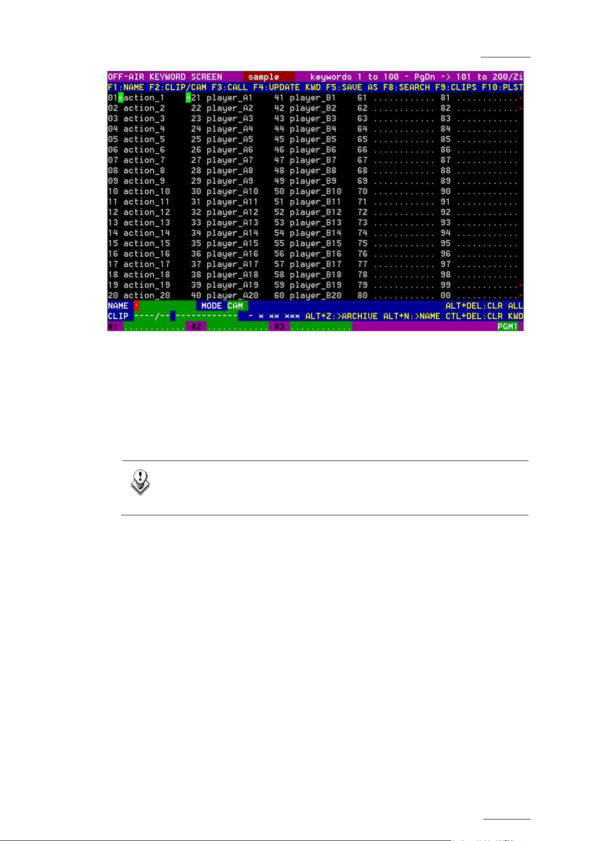
EVS Mult icam Version 10.04 – Operat ing Manual
EVS Broadcast Equipment SA – January 2011
Issue
10.04.A
75
Select a local keywords file from the Setup. If you select “SERVER” as keywords
file in the setup, i.e. the file distributed by the network server, you will not be
allowed to edit it.
Go to the Off-Air Keyword Screen by pressing F7 on the keyboard. If you want to
create a backup copy of the current file, press F5:SAVE AS in that screen (or click
on the function with the stylus) and enter the name of the file you want to create.
This can also be used to create a local c opy of the keywords file distributed by the
Network Ser ver.
Note
If a .KWD file with the same name already exists in the KWD directory, it
will automatically be overwritten by the new file.
To edit a keyword in the current file, move the cursor to the desired keyword
location, using either the arrow keys or the stylus, then type the new keyword.
This one will appear in the Name field at the bottom of the screen. Press ESC to
clear the whole field or <BACKSPACE> to delete the last character. To apply the
value entered in the name field to the selected keyword, press F4:UPDATE KWD,
or click on that function with the stylus.
Repeat this operation for all keywords t o updat e.
Press PgU/PgDn to toggle between Page 1 (keywords 1 to 100) and Page 2
(keywords 101 t o 200), or click on the Up/ Down red arrows on the right side of the
screen.
If your machine is the actual Network s erver, the updated file is automatically sent
to all other users on the network every time a keywor d is updat ed .
Page 86
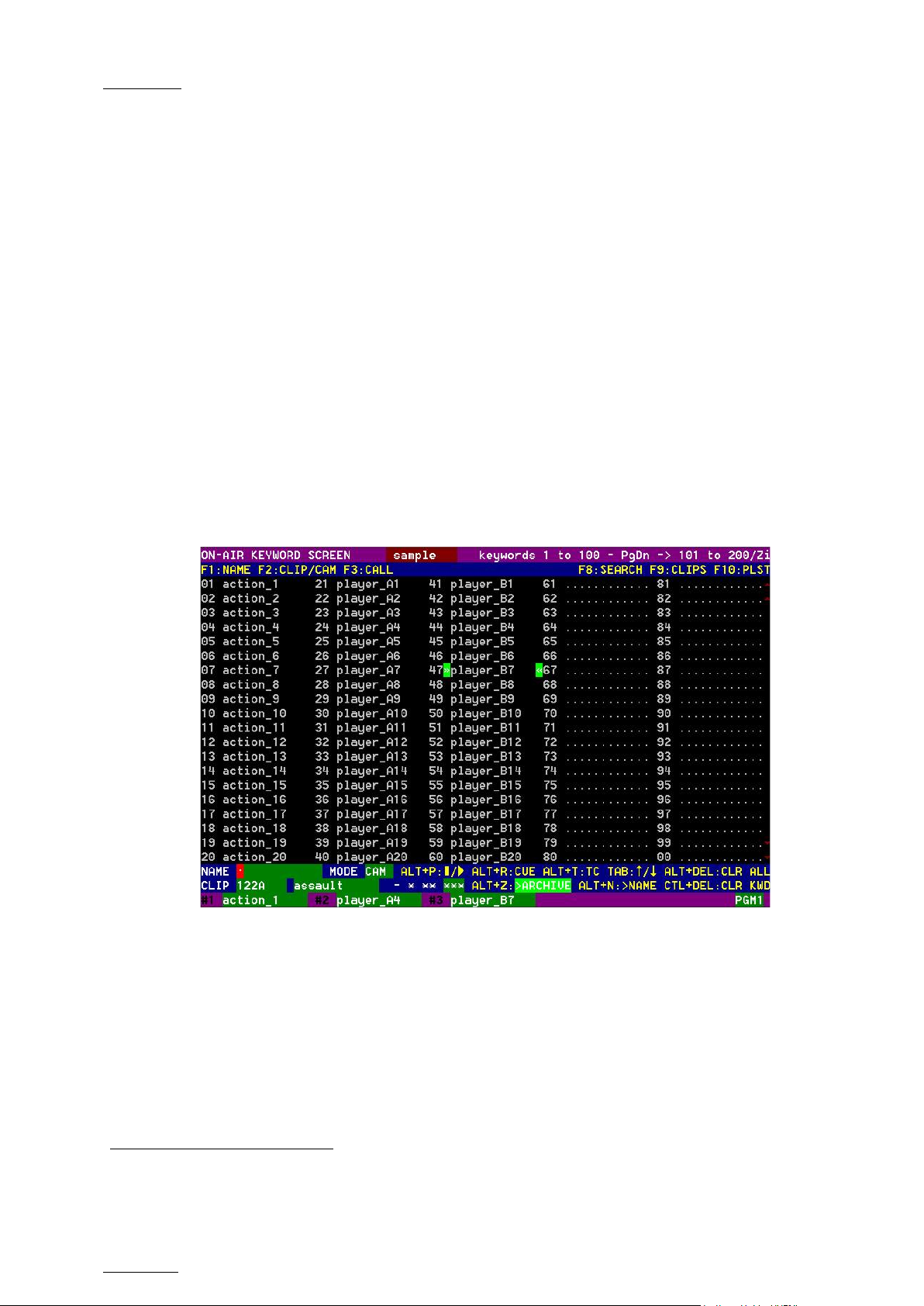
Issue
10.04.A
EVS Multicam Vers ion 10.04 – Operating Manual
76
EVS Broadcast Equipment SA – January 2011
10.2 ASSIGNING KEYWORDS USING THE VGA SCREEN
10.2.1 KEYWORD WINDOWS
Keywords can be assigned to clips using the On-Air Keyword screen (F6:KW1), or
the Off-A ir Keyword screen (F7:KW2).
The On-Air Keyword screen is used to assign keywords to the clip loaded on the
primary channel of the 1
operation.
The Off-Air Keyword screen is used to assign keywords to the clip selected with
the green arrows in the Clip screen or in the VDR Panel, even if this clip is not
loaded on any play channel. This can be useful to allow someone to assist the
main operator for logging operations, without taking any play channel from the
system
The operation of both On-Air and Off-Air Keyword screens is entirely similar.
st
user, meaning that a play channel is used during this
The name of the current keyword file is displayed in the centre of the Title Bar,
against a red background.
Many functions for clip management are similar to the Clip screen: F1:NAME ;
F2:CLIP/CAM ; F3:CALL
ALT+Z:>ARCHIVE, ALT+Fx: selec t the Call Channel from VG A is enabled. Refer to
the des cription of the Clip screen for details about t hese functions.
The ID and name of the clip that keyword are going to be assig ned to is displayed
at the bottom on the screen, along with the keywords, ranking and archive status
already assig ned to that c lip.
1
When calling a clip with the F 3 function in the Off-Air Keyword Screen, the s yst em will automatically switch to the
On-Air Keyword s c r een, since the clip to as s ign keywords to has been loaded on a play channel.
1
, ALT+P:PLAY/PAUSE, ALT+R:RECUE, ALT+T:SET TC;
Page 87

EVS Mult icam Version 10.04 – Operat ing Manual
EVS Broadcast Equipment SA – January 2011
Issue
10.04.A
77
10.2.2 HOW TO ASSIGN A KEYWORD TO A CLIP
Move the cursor t o t he desired keyword and press ENTER, or click on the keyword
with the stylus. The keyword will be assigned to the first available keyword
location on the last line of t he screen. Repeat this to as sig n more keywords (up to
3) to the current clip.
Depending on the CLIP/CAM mode, the keywords will be assigned to the current
camera angle only (CAM mode), or to all camera angles of the current clip (CLIP
mode).
If 3 keywords are already assigned to the clip, the operator has to clear some of
them to be able to assign new k eywords.
10.2.3 HOW TO CLEAR A KEYWORD WITH THE KEYBOARD
Press <TAB> to move the arrow cursor to the lower area of the screen. Red
arrows will appear around one of the keywords or ranking values. Use the ←/→
arrows to select the keyword to remove, and press CTRL+DEL. Press the <TAB>
key again to move the arrow cursor back to the keywords list.
10.2.4 HOW TO CLEAR A KEYWORD WITH THE STYLUS
Click on the keyword to remove on the last line, the click on the CTRL+DEL:CLR
KWD area on the screen, or press CTRL+DEL.
10.2.5 HOW TO EDIT THE RANKING OF THE CURRENT CLIP WITH
THE KEYBOARD
Press the <TAB> key to move the cursor to the lower area of the screen Use the
←/→ arrows to select the desired ranking, and press ENTER. The selected
ranking is highlighted in green.
10.2.6 HOW TO EDIT THE RANKING OF THE CURRENT CLIP WITH
THE STYLUS
Click on the desired ranking, it becomes highlighted in g reen.
Page 88

Issue
10.04.A
EVS Multicam Vers ion 10.04 – Operating Manual
78
various function keys
Area displaying the list of keyword list on the page
EVS Broadcast Equipment SA – January 2011
10.2.7 HOW TO CLEAR ALL KEYWORDS AND THE RANKING OF A CLIP
Press ALT+DEL or click on ALT+DEL:CLR ALL: all keywords assigned to the clip
will be removed, and the ranking will be res et to the lowest leve l (“-“).
10.2.8 HOW TO NAME A CLIP USING THE KEYWORDS:
Move the cursor to the desired keyword and press ALT+N. The keyword is added
at the end of the current name if t here is enough space left.
Note
To clear the name of a clip, press ESC to empty the Name field, then
press F1 to assign this “empty name” to the clip.
10.3 SEARCHING THE DATABASE USING THE VGA SCREEN
10.3.1 SEARCH WINDOW
Press F8 to access the Search Screen. The VGA Search screen is made up of
several areas that will be named as follows, f rom the top to the bottom:
1. Title bar Bar containing the following elements from left to right:
2. Function bar
3. Keyword list
• Screen nam e
• Name of the current keywords file displayed against a
red background in the centre of the Title Bar
• Keyword page displayed.
Bar displaying information on the
available and their purpose.
specified in the title bar.
4. Operation tab
5.
Search Criteria
area
Bar displaying the key combinations available and the
associated actions.
Area displaying the search criteria available
Page 89
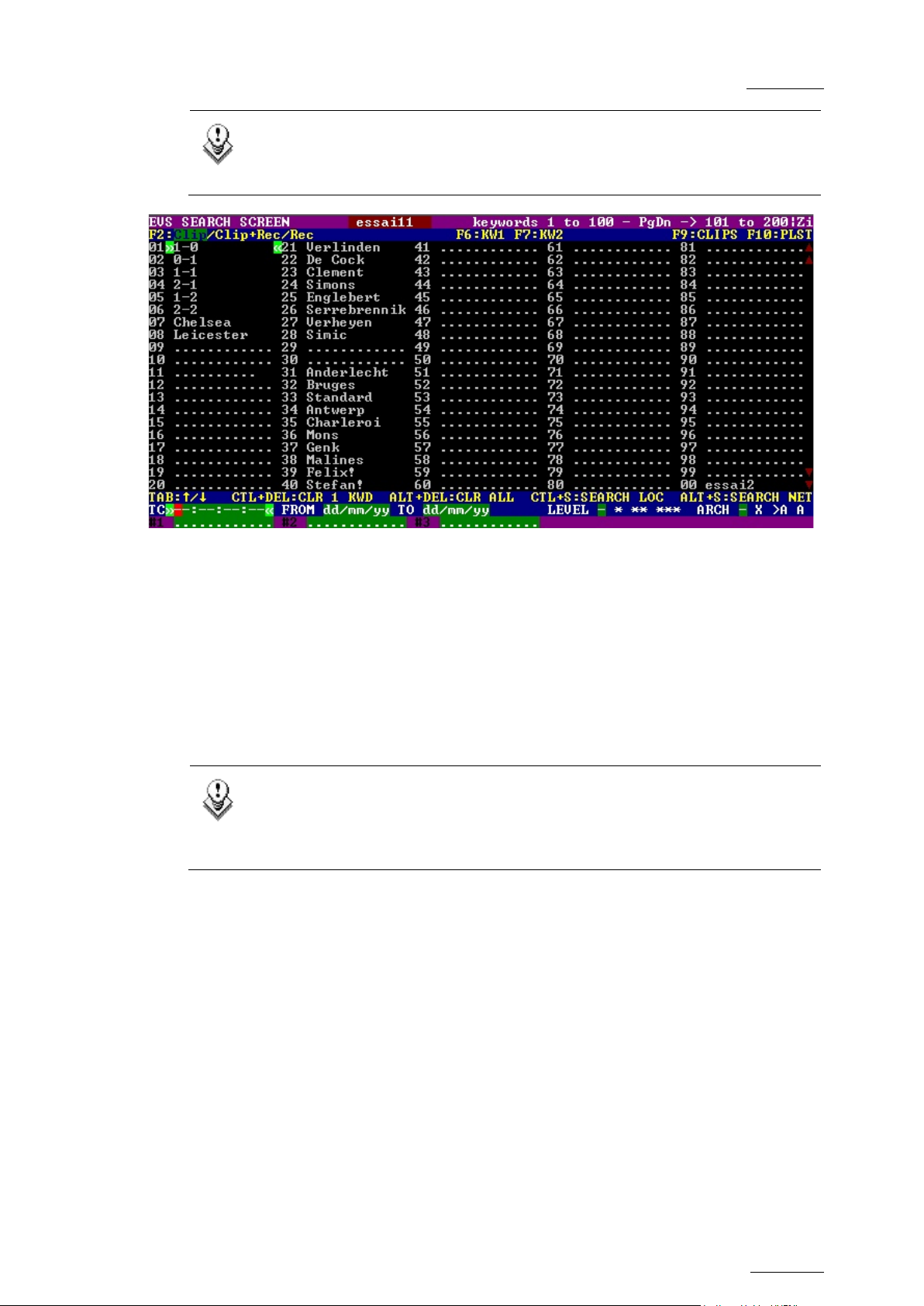
EVS Mult icam Version 10.04 – Operat ing Manual
EVS Broadcast Equipment SA – January 2011
Issue
10.04.A
79
Note
Use the <TAB> key to shift from the Keyword list to the Search Criteria
area and vice versa.
10.3.2 SEARCH CRITERIA AND SEARCH OPTIONS
SEARCH CRITERIA
Different criteria can be combined to search the database. They can be defined in
the Search Criteria are a availab le at the bottom of t he screen.
When you access the Search screen, the criteria that were last defined are still
available on the screen.
Note
If the red cursor is located on another field in the Search Criteria area,
use the ←/→ arrow keys to move from one field to the previous or next
one, until the red cursor is positioned on the r eq uested field .
Page 90

Issue
10.04.A
EVS Multicam Vers ion 10.04 – Operating Manual
80
to the
EVS Broadcast Equipment SA – January 2011
Criteria Description
Timecode
Date from / to
Level /
Ranking
This restricts the search to the clips containing the timecode
specified in this field. The timecode search is not applied on
growing c lips.
To define a timecode, type the desired value when the red text
cursor is visible in that field.
The <BACKSPACE> key can be used to clear the last digit
entered.
This restricts the search to clips created between these 2 dates
specified in these fields.
If only Date to field is defined, all clips created before that date
will be considered.
If only Date from f ield is defined, all clips created after that date
will be considered.
The <BACKSPACE> key can be used to clear the last digit
entered. Press the <TAB> key again to move the cursor back to
the keywords list.
This restricts the search to the clips with a ranking equal or
higher to the ranking defined in that screen.
Press the ←/→ arrow keys until reaching the desired ranking,
and press ENTER. The selected ranking is highlighted in green.
Keywords
Archive status
Press the <TAB> key again to move the cursor back
keywords list.
This restricts the search to the clips containing all keywords
defined in t his screen.
To assign a keyword, move the cursor to the desired keyword
and press ENTER, or c lick on t he keyword using the stylus.
A maximum of 3 keywords can be us ed as search criteria. If all 3
keyword locations are already occupied, the operator needs to
clear some of them to selec t new keywords.
This restricts the search to the clips having the archive status
selected.
Parameter On the VGA
None (default) clips not archived X
clips to be archived >A
clips archived A
Page 91

EVS Mult icam Version 10.04 – Operat ing Manual
EVS Broadcast Equipment SA – January 2011
Issue
10.04.A
81
SEARCH OPTIONS
In addit ion to the search criteria available at the bottom of t he screen, two search
options are accessible from the Function keys F2 and F4:
Consider Record train s and / or clips in the Search
This option allows the inclusion of record trains in the results in searches with
timecode cr iteria. Press F2 to toggle between CLIP / CLIP+REC / REC.
Consider timecodes from the LTC and/or USE R TC tables in the Search
This option makes it possible to take into account the timecodes from the LTC
and/or the USER TC tables in searches with timecode criteria. Press F4 to toggle
between LTC / USER / LTC+USER.
10.3.3 CLEARING KEYWORDS IN THE SEARCH CRITERIA
HOW TO CLEAR A KEYW ORD WITH THE KEYBOARD
Press <TAB> to move the arrow cursor to the lower area of the screen. Use the
←/→ arrows to move the cursor to t he keyword to remove, and press CTRL+DEL.
Press the <TAB> key again to move the arrow cursor back to the keywords list.
HOW TO CLEAR A KEYW ORD WITH THE STYLUS
Click on the keyword to remove on the last line, the click on the CTRL+DEL:CLR
KWD area on the screen, or press CTRL+DEL.
HOW TO CLEAR ALL CRITERIA AT ONCE
Press ALT+DEL or click on ALT+DEL:CLR ALL: all keywords, timecode, Date
from and Date to fields assigned as search criteria will be removed, and the
ranking will be reset to the lowes t leve l (“- “).
When performing the search, only the clips matching all criteria defined by the
operator will be included in the search results. Press CTRL+S (or click on the
corresponding area) to search the local database, or press ALT+S (or click on the
corresponding area) to search the entire network database.
Page 92

Issue
10.04.A
EVS Multicam Vers ion 10.04 – Operating Manual
82
10.3.4 SEARCH RESULTS
The results of the database search are displayed in the Search Results screen. If
new clips are created after the search, which match the search criteria, they will
be automatically added to the list.
The Search Results screen includes the follow ing areas:
• At the bottom of the scr een, the search crit eria ar e d isplayed for information.
• In the centre of the screen, a list of all m atching clips is displayed.
EVS Broadcast Equipment SA – January 2011
CLIP INFORMATION
For each clip, the following informat ion is d isplayed :
• position in the list
• cli p ID
• clip name
• timecode of Short IN and Short OUT points
Timecodes f rom the LTC table are d isplayed in g rey/black.
Timecodes from the USER TC table are displayed in yellow.
• ranking
• archive status
• current keywords.
Page 93

EVS Mult icam Version 10.04 – Operat ing Manual
EVS Broadcast Equipment SA – January 2011
Issue
10.04.A
83
BROWSING THROUGH RESULTS AND LO ADING A CLIP
The operator can browse this list with the ↑/↓ arrow keys, PgUp, PgDn, Home
and End keys.
If the Browse mode of that screen is ON (F5:BROWSE), the clip will be loa ded on
the primary play channel as soon as it is selected.
If the Browse mode is OFF, the operator must press ENTER after selecting the clip
to load it.
POSSIBLE ACTIONS
Many functions from the Clip screen are also available from the Search Results
screen:
Note
When a clip is displayed in the search results with a timecode from the
VITC table (when this search option has been selected), the clip is loaded
with this timecode even if the primary TC is the LTC.
F1:NAME F2:CLIP/CAM F3:CALL
ALT+P:PLAY/
PAUSE
To return to the Search screen to perform a new search, press ALT+S or F8. The
previous search criteria are kept until the operator selects new criteria.
ALT+R:RECUE ALT+T:SET TC ALT+Z:>ARCHIVE
How to Add a Clip to the Current Playlist from the Remote Panel
To add a clip from that list to the current playlist, call up the clip, then press
INSERT or ENTER on the Remote Panel.
How to Add the Search Results to the Current Playlist from th e VG A
It is possible to directly add one or all search results (clips only) to the current
playlist:
• Press INSERT on the selected clip to insert only the highlighted one.
• Press SHIFT+INSERT to insert all clips to the end of the current playlist.
Page 94
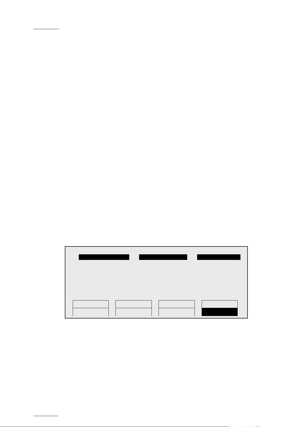
Issue
10.04.A
EVS Multicam Vers ion 10.04 – Operating Manual
84
1
player_B10123
2
action_689012
3
keyword89012
Push
Aux Clip
Sort->TC
Post-Roll
>Archive
***
Name
Cam
EVS Broadcast Equipment SA – January 2011
10.4 ASSIGNING KEYWORDS USING THE REMOT E PANEL
10.4.1 KEYWORD SETTINGS
A keywords file must be selected in the Setup to enable the keyword assignment
functions on the EVS Remote Panel.
• In the Setup menu of the remote, the operator can choose between 2 different
keyword modes: “List” (default) or “Numeric”.
• In LIST mode, the list of keywords will appear on the LCD display by group of
8 keywords, and the operator can select the keyword by pressing the
corresponding F_ key. The advantage is that the keywords are visible to the
operator, but this mode can be slow if he has to browse through a long list of
keywords.
• In NUMERIC mode, the list of keywords is not visible on the LCD display, and
the operator selects a keyword by entering its position in the list with the F_
keys. He can know the position either from a hardcopy of the keywords list, or
by looking at one of the VGA Keywords screens, or still from his memory...
This mode is faster to operate, but in most cases the operator will need to
have the complete list of keywords available next to him.
10.4.2 ASSIGNING KEYWO RDS IN LIST MODE
To assign keywords to a clip in list mode, recall the clip, then press MENU to
access the secondary clip menu on the Remote Panel.
F1:action_1 F6:action_6
F2:action_2 F7:action_7 111A
F3:action_3 F8:action_8
F4:action_4 F9:Prev.page p.01
F5:action_5 F0:Next page
The LCD display a page containing 8 keywords. Press F9/F10 to access the
previous/next keywords page. To assign a keyword to the current clip, press the
F_ key corresponding to t he desired keyword on the LCD display.
Depending on t he CLIP/CAM mode defined by the D k ey, the selected keyword will
be assigned only to the camera angles loaded on the channels fully controlled by
the operator at that time (CAM mode), or to all camera angles of the clip (CLIP
mode). T he keyword will b e assigned to the f irst availab le keyword location on the
st
1
line of the LCD display. If the Keyword Info parameter of the Setup is set to
“Yes”, it will also appear on the OSD of the corresponding output monitors if the
Page 95

EVS Mult icam Version 10.04 – Operat ing Manual
EVS Broadcast Equipment SA – January 2011
Issue
10.04.A
85
PGM1 Cam A *PRV1* Cam B
Push
PgmSpd
Sw To In
Pref
>Archive
***
Name
Cam
***
Local
Sync Prv
2nd CTRL
Cam A
Cam B
Cam C
Cam D
current picture is the Short IN point of the clip.
If all 3 keywords location are occupied, the operator has to clear some of them to
be able to assign a new keyword to that clip.
To clear one of the keywords alread y assigned, pr ess CLEAR + F1 / F2 / F3 in the
secondar y clip menu.
The clip can also be named based on the keywords. Press the Name function (C
key) in the secondary menu, then select keyword s. The keywords will be added to
the name of the clip, up to 12 characters. In this mode, the name of the clip is
visible on the OSD. It can also be edited with the following keys:
• CLEAR: erase the last character
• SHIFT+CLEAR: insert a blank
• SHIFT+F1-F10: insert a number (1, 2, 3, …, 8, 9, 0)
Once the name is complete, press ENTER to valid ate or MENU t o cancel.
While the operator is in t he secondary menu, he has full control of the curr ent clip
with the lever, PLAY key and jog dial, so he can brows e the clip and start a replay
at any time.
It is also possible to assign keywords and ranking to a clip before it is created.
Indeed, when a record train is loaded, as soon as the operator marks an IN or
OUT point, the main and secondary menu changes to make the keyword functions
available.
P.1 B.1 Clips: Local Records: Local
PL 11: < >
Msg:
The SHIFT+A function of the main menu, normally used by the Reset CAM
function, can be used to define the ranking, without entering the secondary menu.
For additional functions like selecting keywords, flagging the future clip for
archiving, marking it to be pushed to another machine, defining its name from the
keywords, they can be performed from the secondary menu, exactly the same way
as for a clip already stored. All these settings are memorized and will be applied
to the clip when it is created.
Page 96
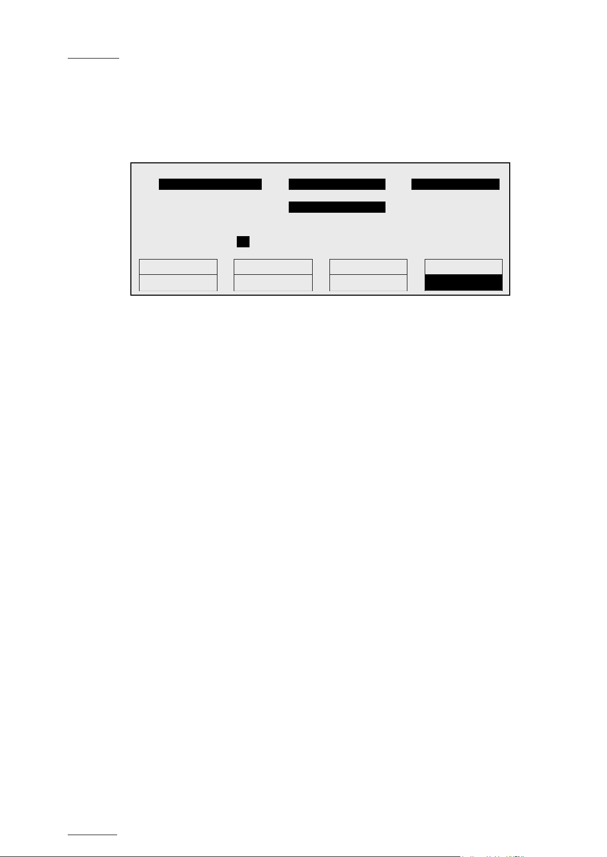
Issue
10.04.A
EVS Multicam Vers ion 10.04 – Operating Manual
86
1
player_B10123
2
2action_689012
3
keyword89012
action_889012
111A
Push
Aux Clip
Sort->TC
PostRoll
>Archive
***
Name
Cam
10.4.3 ASSIGNING KEYWORDS IN NUMERIC MODE
To assign keyword s to a clip in numeric mode, recall the clip, then press MENU to
access the secondary clip menu on the Remote Panel.
Enter keyword # 8 with F_ keys + ENTER
Enter the keyword position in the list using the F_ keys. Every time a new digit is
entered, the corresponding keyword is displayed in the highlighted area in the
centre of the LCD screen, to allow the operator to validate the entry before
confirming it. If a wrong digit is entered, press the CLEAR key to delete it. Once
the right keyword is found, press ENTER to confirm or MENU to cancel.
EVS Broadcast Equipment SA – January 2011
The rules for keyword assignment and deleting keywords are identical between
LIST and NUMERIC modes.
10.5 SEARCHING THE DATABASE USING THE REMOT E PANEL
Keywords and ranking assigned to clips can be used to search the clips database.
When the current element on the primary channel is a record train, the Search
function is dir ectly available from t he C position in the secondary menu. T o call it,
press MENU to enter the secondary train menu, then press once the C key.
When the current element on the primary channel is a clip, the Search function is
still available from the same location, but it is “hidden” behind the Name function.
To call it in this case, press MENU to enter the secondary clip menu, then press
twice the C key.
In both cases, the LCD display becomes (in LIST mode):
Page 97

EVS Mult icam Version 10.04 – Operat ing Manual
EVS Broadcast Equipment SA – January 2011
Issue
10.04.A
87
1
keyword89012
2
2 keyword89012
3
keyword89012
Reset
Archive
FromDate
ToDate
Return
***
Srch Loc
Srch Net
F1:action_1 F6:action_6
F2:action_2 F7:action_7
F3:action_3 F8:action_8
F4:action_4 F9:Prev.page p.01
F5:action_5 F0:Next page
Keywords
They can be selected for use as search criteria the same way they were selected
to be assigned to a clip, in LIST or NUMERIC mode. Up to 3 keywords can be
selected as search criteria. If all 3 keywords locations are used, some of them
must be cleared before selecting a new keyword. Press CLEAR + F1 / F2 / F3 to
clear to corresponding keyword location.
Ranking
A ranking can also be used as the only search criteria, or can be combined to the
keywords as an additional criterion. Press the B key several times to select the
desired ranking.
The RESET key (SHIFT+A) can be used at any time to clear all 3 keyword
locations and reset the ranking to the lowes t level.
Archive
This f ield allows selecting archive status for search criteria.
Parameter On the Remote
None (default) Archive
Clips not archived >Archive
Clips to be archived > Archive (blinking)
Clips archived >Archive
It is possible to include trains in the search. The B key allows to toggle between
CLIPS/CLIPS+REC/REC.
Fro m Date / To Date
Selecting a From Date and To Dat e can be done using the SHIFT+C and SHIFT+D
keys. Pressing on any of those keys changes the display on the key to dd/mm/yy
to indicate the date format. The F keys are used to enter the date, the Clear key
being the <BACKSPACE>.
Page 98

Issue
10.04.A
EVS Multicam Vers ion 10.04 – Operating Manual
88
EVS Broadcast Equipment SA – January 2011
To search only for a specific date, use the same date twice in the From Date and
To Dat e fields.
Once a date is entered, pressing Clear SHIFT+C or Clear SHIFT+D reset the
FromDate or ToDate to the d efault parameter (dd/mm/ yy).
RESET
The RESET key: resets the default values of the search criteria (no from/to date)
and set the default TC to t he TC of loaded on the PGM.
RETURN
The RETURN key (A) is used to exit the Search function without performing any
search.
Sea rch LOC / S earch N ET
Once the search criteria are defined, press SRCH LOC (C) to search the local
clips database, or SRCH NET (D) to searc h the entire networ k database.
The matching clips are the ones that contain all keywords used as search cr iteria,
and that have at least
If matching clips are found, the remote will automatically be in Browse mode (the
BROWSE key is red), allowing the operator to quickly view the Short IN of each
clip corresponding to the search criteria by rotating the jog dial. To be able to jog
inside a clip, d isable t he Browse mode by pressing on t he BROWSE key and move
the jog dial. To return to the Browse mode inside the search results, press the
BROWSE key again.
Search results are reset when going by to LIVE mode, or when a new search is
performed.
If no matching clips are found, a message notifies the operator.
the requested ranking.
Adding t he search results to the current playlist
It is possible to directly add all s earch results (clips only) to the current playlist.
Press ENTER on the selected clip to insert only that one.
Press SHIFT+ENTER to insert all clips to the end of the current playlist.
Page 99

EVS Mult icam Version 10.04 – Operat ing Manual
EVS Broadcast Equipment SA – January 2011
Issue
10.04.A
89
11. Playlist Management
11.1 GENERAL INFORMATION
PLAYLIST CREATION
Playlists can be created on the server
• via the LSM Remote Panel and/or the Multicam user interface
• by means of the Playlis t Panel application in IPDirector
• via external protocols..
LIMITATIO N ON PLAYLIST AND TIMELINE ELEMENTS
A playlist can include up to 1000 element s.
Up to 16000 playlist elements can be saved on a server.
Up to 48000 tempor ary playlist elements, available f or undo and red o actions, can
be stored on a server. They will be purged each time the Multicam application is
closed.
PLAYLIST LOCATION
All playlists created are automatically stored on the banks dedicated to playlists
and timelines on the server, i.e. the bank 10 of each page.
Playlists on page 10 are not available from the EVS Remote Panel. These playlists
are res erved for external protocols (Odetics, Louth VDCP, EVS AVSP).
REFRESHING THE PLAYLIST INFORMATION
Playlist information is not permanently refreshed on the network. The playlist
information for a remote playlist bank is only transferred when entering that bank.
If you are already connected to a remote playlist bank, you need to press
SHIFT+F10 again to refresh the playlist information for this bank.
Page 100

Issue
10.04.A
EVS Multicam Vers ion 10.04 – Operating Manual
90
Effect
Edit All
Insert
Speed
FX Dur
Delete
Clr Unav.
OtherAng
Replace
MakeLoc
Redo
Undo
EVS Broadcast Equipment SA – January 2011
11.2 PLAYLI ST MODES ON THE REMOT E PANEL
11.2.1 INTRODUCTION
Two modes are available on the Remote Panel to access and manipulate the
playlists: The Playlist Edit mode and the Playlist Playout mode:
• The Playlist Edit mode is used to modify the playlist.
• The Playlist Playout mode is used to roll the playlist on air.
Editing the playlist in Playlist Playout mode is not possible.
11.2.2 ACCESSING THE PLAYLIST EDIT MODE
ACCESS
When you load a playlist press ing the PLST key on the Remote Panel, you direct ly
enter the Playlist Edit mode. The first frame of the element highlighted in the
playlist appears on the PGM. At the start, full control will be on the PGM side;
scrolling through the playlist can be done here.
From t he Playlist Playout mode, you need to press the EDIT function (D button) or
move the jog dial to return to the Playlist Edition mode from where you can edit
the playlist.
OVERVIEW
The main menu in the Playlist Edit mode available on the Remote Panel dis pla y is
the following:
A second ary menu is also available when you s elect MENU from t he main menu in
the Playlist Edit mode. All commands are not always available in the secondary
menu:
In Playlist Edit mode, the duration displayed in the top right corner of the LCD
screen is the playlist tot al dur ation, f rom the beginning to t he end
.
For more details on the main and sec ond ary menus of the Playlist Edit mode, refer
to the section 11.9 ‘Overview of Editing Functions in Playlist Edit Mode’, on page
100.
 Loading...