

Page 1
USER MANUAL
Version 6.15 - April 2013
Page 2

Page 3

IPClipLogger- Version6.15- User Manual
Copyright
EVS Broadcast Equipment S.A.– Copyright © 2013. All rights reserved.
Disclaimer
The information in this manual is furnished for informational use only and subject to
change without notice. While every effort has been madeto ensure that the information
contained in this user manual is accurate, up-to-date and reliable, EVS Broadcast
Equipment cannot be held responsible for inaccuracies or errors that may appear in this
publication.
Improvement Requests
Yourcomments will helpus improve the quality of the user documentation. Do not
hesitate to send improvement requests, or report any erroror inaccuracy on this user
manual by e-mail to doc@evs.com.
Regional Contacts
The address and phone number of the EVS headquarters areusually mentioned in the
Help > About menu in the user interface.
You will find the full list of addresses and phone numbers of local offices either at the end
of this usermanual (for manuals on hardwareproducts) or at the followingpage on the
EVS website: http://www.evs.com/contacts.
User Manuals on EVS Website
The latest versionof the user manual, if any, and other user manuals on EVS products
can be found on the EVS downloadcenter, on the following webpage:
http://www.evs.com/downloadcenter.
I
Page 4

EVS BroadcastEquipment S.A.- April 2013
II
Page 5

IPClipLogger- Version6.15- User Manual
Table of Contents
TABLE OF CONTENTS III
1. INTRODUCTION 1
1.1. Product Description 1
1.2. OpeningIPClipLogger 1
1.3. Typical Workflows 2
1.4. Overview of the Process 3
2. USER INTERFACE 4
2.1. Overview of the IPClipLogger Window 4
2.2. Recorder Channels Selection Area 7
2.3. Clips List Pane 8
2.3.1. Introduction 8
2.3.2. Overview of the Clips List Pane 9
2.3.3. Tree View 10
2.3.4. Quick Text Search Area 13
2.3.5. Elements Grid 14
2.4. Clip Infos Pane 21
2.4.1. Purpose 21
2.4.2. Overview of the Clip Infos Pane 21
2.4.3. Timecode Fields Display 25
2.4.4. Video Display 25
2.4.5. Audio Configuration and Monitoring 26
2.4.6. Jog Bar 28
2.4.7. Player Full Screen Mode 29
2.4.8. Interest Level Buttons 29
2.4.9. Metadata Profiles 30
2.5. Logs Panes 32
2.5.1. Purpose 32
2.5.2. Overview of the LoggingPane 33
2.5.3. Overview of the AssociatedLogs Pane 34
2.5.4. LogInfo 35
2.5.5. Logs Grid 36
2.6. Keywords Grids 36
2.6.1. Purpose 36
2.6.2. Overview of the Keywords Grid Pane 37
2.6.3. Keyword Types 38
2.7. Message Pane 39
2.7.1. Purpose 39
2.7.2. Messages Display 39
Table of Contents III
Page 6

EVS BroadcastEquipment S.A. - April2013 Issue 06.15.B
2.7.3. Message Acknowledgment 39
2.7.4. Messages Filter 40
3. WORKING WITH MULTIPLE LOGGING SESSIONS 41
3.1. Introduction 41
3.2. Managing Several Logging Sessions 41
4. SEARCHING FOR MEDIA 42
4.1. Search Types 42
4.2. Branch Selection in the Tree 42
4.3. Quick Text Search 43
4.3.1. Purpose and Context of Use 43
4.3.2. Search for Synonyms 43
4.3.3. Quick Text Search Field Display 44
4.3.4. Quick Text Search Syntax Rules 44
4.3.5. Autocomplete Function in Quick Text Search Field 45
5. LOADING MEDIA 49
5.1. Introduction 49
5.2. Possible Loading Actions 49
5.3. Loading a Train or a Recording Ingest 51
5.3.1. Loading a Train or a Recording Ingest in Player Mode 51
5.3.2. Loading a Train in Live Mode 54
5.4. Loading a Clip 57
5.4.1. How to Load a Clip 57
5.4.2. How to Load a Linked Clip 57
6. MOVING THROUGH MEDIA 58
6.1. Introduction 58
6.2. Transport Functions 58
6.2.1. Using the Jog Bar 58
6.2.2. General Transport Buttons andShortcuts 58
6.2.3. Fast Forward and Fast Rewind Speed 60
6.3. Jumping to a GivenTimecode within the Loaded Media 61
6.4. Jumping to a Log within a Clip 62
6.5. Browsing in Video Material with the ShuttlePRO 62
7. MANAGING WORK BIN 63
7.1. Purpose 63
7.2. How to Set a Work Bin 63
7.3. How to Reset a Work Bin 63
7.4. How to Go To a Work Bin 63
IV Table of Contents
Page 7

IPClipLogger- Version6.15- User Manual
8. CREATING A CLIP 64
8.1. Introduction 64
8.2. Clip Creation Buttons and Shortcuts 64
8.3. Creating Clip(s) in Player Mode 66
8.3.1. How to Create a Clip ora Sub-Clip 66
8.3.2. How to Trim a Clip 68
8.4. Creating Clip(s) in a Live Session 68
8.5. Creating Clips on a Streamed Feed 69
9. ADDING LOGS TO MEDIA 72
9.1. Introduction 72
9.2. LogCreation Buttons and Shortcuts 73
9.3. Configuring F Keys to Add Logs 73
9.3.1. Purpose 73
9.3.2. How to Configure an F Key 74
9.4. Live Logging 75
9.4.1. Introduction 75
9.4.2. How to Log LIVE Action 76
9.5. Retroactive Logging 78
9.5.1. Introduction 78
9.5.2. How to Log a Recorded Train 78
9.5.3. How to Log an Existing Clip 79
9.5.4. Managing Existing Logs 81
10. ASSIGNING KEYWORDS TO MEDIA 82
10.1. Introduction 82
10.2. Conditions for the Use of a Keyword 82
10.3. Assigning a Keywordby Direct Entry 82
10.3.1. Autocomplete List 82
10.3.2. How to (Un)Assign a Keyword to Media by Direct Entry. 83
10.4. Assigning a Keywordfrom a Keyword Grid 84
10.4.1. How to Display the Keywords Grid Pane 84
10.4.2. How to Display Keyword Grids 84
10.4.3. How to (Un)Assign a Keyword to Media from a KeywordGrid 85
Table of Contents V
Page 8

EVS BroadcastEquipment S.A.- April 2013
VI Table of Contents
Page 9

IPClipLogger- Version6.15- User Manual
1. Introduction
1.1. Product Description
IPClipLogger is a simple stand-alone application designed for an easy and quick logging of
media, which means adding reference points to a specific frame in a video media. Users
have the possibility to create log entries directly during the event, or later on by moving
through the recorded media.
The IPClipLogger window is an integrated window from which it is possible to perform all
the actions related to several loggingworkflows. This includes searchingtools to find the
correct media from the list of clips, a Playerpane to watch the mediaand make clips from
it, a Logging paneto add logs to clips. Metadata, such as keywords, metadata profiles, log
color or interest level, can be associated to clips or logs from this window as well. All the
clips representing a story, and theirassociated logs andmetadata, can be automatically
sent to a workingbin. Thelogged clips couldthen be sent to targets for post-production.
Shortcuts are available for most of the operations to speed up the process and avoid using
the mouse.
In some workflows, takes are recorded from several camera angles at the same time. All
the operations performed from the IPClipLoggeron such a media are done for all the
camera angles the users want to work with. This includes, among others, logging, clipping
andsub-clipping.
The IPClipLogger offers the possibility to log different media at the same time from
several tabs from which it is easy to switch.
Floating licenses aresupported, so a large number of stations can be equippedwith the
IPClipLogger application.
Note
The IPClipLogger application works with floating licenses importedin the
database.
1.2. Opening IPClipLogger
To openthe IPClipLogger, click the corresponding icon .
This will display a login screen where users have to enter their own username and
password.
At first opening, a single tab, set to be used in Player mode, is shown in the IPClipLogger
window. Then, additional tabs can be opened to work with Live sessions. See section
"Working with Multiple Logging Sessions" on page 41 to know how to proceed.
1. Introduction 1
Page 10

EVS BroadcastEquipment S.A. - April2013 Issue 06.15.B
1.3. Typical Workflows
Overview
The IPClipLogger supports several workflows listed below.
• Watch a live broadcast, create clips from it and add logs to these clips
• Select anexisting clip and add logs to it
• Select anexisting clip, create a sub-clip from it and add logs to this sub-clip
Note
The workflow which consists of logginga live broadcast (record train) without
first making clips is not in the scope of the IPClipLogger. It is supportedby the
IPLogger module of the IPDirector software.
Modes of Use
To match those different workflows, the IPClipLogger provides two modes of use.
• Player mode: the IPClipLogger window contains a Video Display to watch the media,
andtransport functions to browse through the loadedmedia.
This mode will always be used when logging is done on an existing clip, after the live
event. It can also be used when users make clips and logs on a live broadcast.
• Live mode: the IPClipLoggerwindow does not contain any Video Display.
This mode can only be used when a live broadcast is being clipped andlogged and
users watch the scene being recorded live or on a monitor.
In case several cameras arerecording the event, clips and logs will be created on the
camera angles selected by the users.
Context of Use
Reality shows and News are, among others, the main business environments that will
benefit from the use of IPClipLogger.
In News workflows, a large amount of material is received every day. All the media that
will be archived need to beclearly identified and interesting events must be flagged to be
quickly retrieved later on if required. The IPClipLogger is designed to easily fulfill those
tasks.
Librarians or journalists are generally in charge of those operations. They will beable to
search for a clip, load the clip on the Player pane and identify it with a name or a unique
identifier, keywords anda metadata profile. They will add logs to the clip and, if logs
already exist for that clip, they will be able to review them and possibly edit them. A
description, keywords andother categorizing metadata can be associated to logs.
The Player modewill be used in this kind of workflow.
2 1. Introduction
Page 11

IPClipLogger- Version6.15- User Manual
In Reality Show workflows, loggers generally work during the recording of sequences.
This can be done by watching the scene live, so the Live mode of the IPClipLogger will be
used. But, this can also bedone by searching for an ingest being recorded and then
loading it on the Player pane, so the Player mode will fit the users’ needs.
Afterwards, story editors will review the clips and logs recorded by the loggers and they
still can update clips or create sub-clip from an existing clip.
1.4. Overview of the Process
The table below details the different steps of the process and the corresponding sections
describing each step.
Step Section
Defining shortcuts for the creation of
logs and associated metadata
Searching for media "Searching for Media" on
Loading media "Loading Media" on page49√ √
Browsing a clip "Moving through Media"
Defining the Work bin "ManagingWork Bin" on
Creating a clip and defining its
metadata
Adding logs to a clip and defininglog
metadata
"Configuring F Keys to
Add Logs" on page73
page 42
on page 58
page 63
"Creating a Clip" on page64√ √
"AddingLogs to Media" on
page 72
Live
Mode?
√ √
- √
- √
√ √
√ √
Player
Mode?
1. Introduction 3
Page 12
EVS BroadcastEquipment S.A. - April2013 Issue 06.15.B
2. User Interface
2.1. Overview of the IPClipLogger Window
Introduction
The layout of the IPClipLogger window slightly differs between the Player Session tab and
a Live Session tab.
Illustration
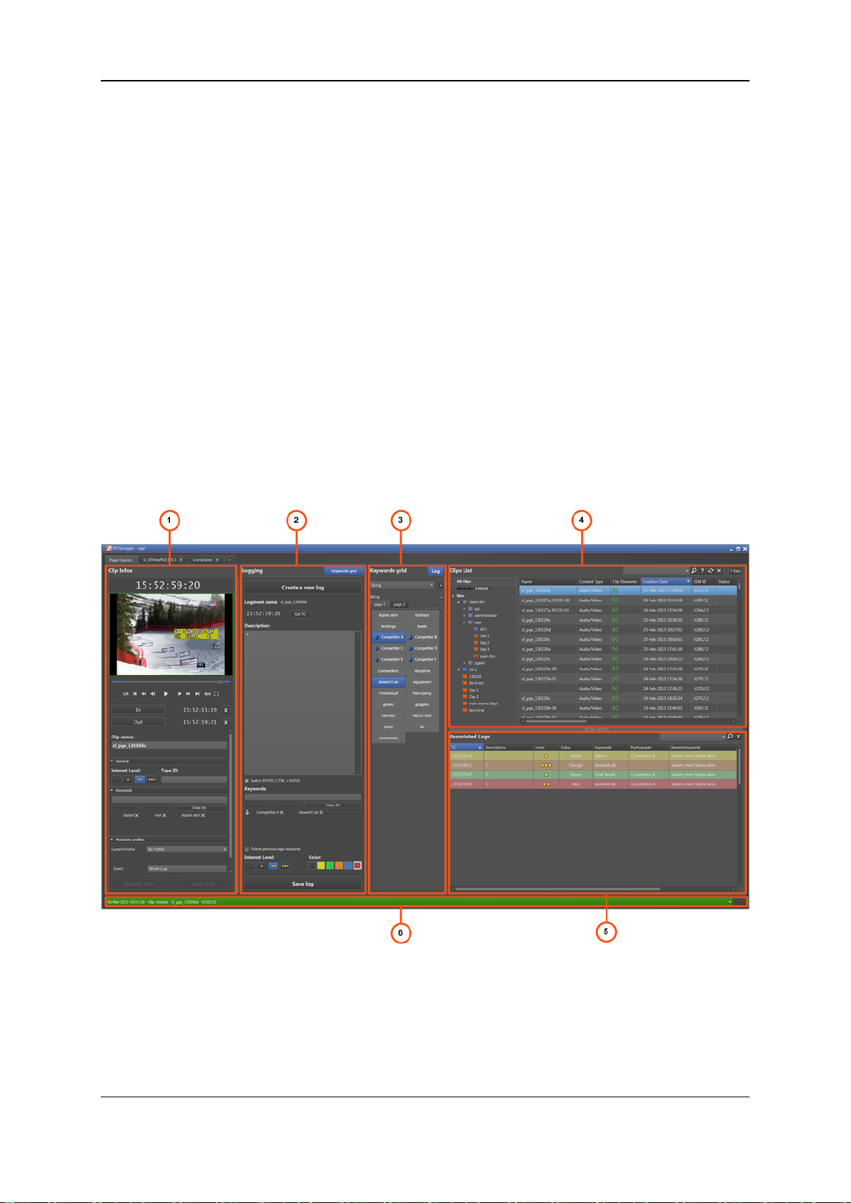
Player Session Tab
The Player Session tab of the IPClipLogger window contains the areas highlighted on the
screenshot below:
4 2. User Interface
Page 13
IPClipLogger- Version6.15- User Manual
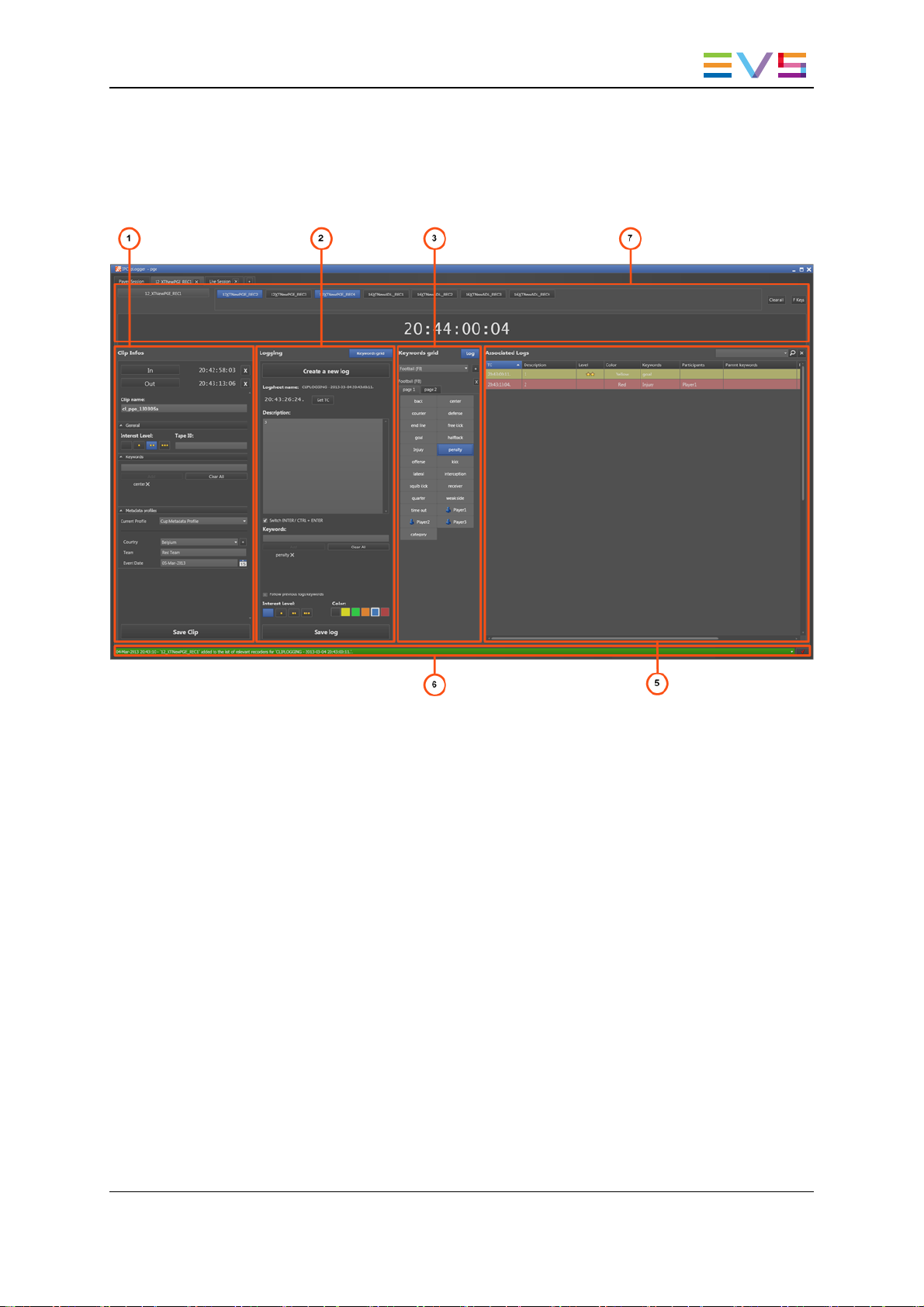
Live Session Tab
A Live Session tab of the IPClipLogger window contains the areas highlighted on the
screenshot below:
2. User Interface 5
Page 14

EVS BroadcastEquipment S.A. - April2013 Issue 06.15.B
Area Description
The table below describes the various parts of the IPClipLogger window:
Area Description
1. Clip Info
pane
2. Logging
pane
3. Keywords
Gridpane
5. Clips List
pane
This pane is used to create a clip and to enterclip metadata for the
clip being created: a name, an interest level, keywords and a
metadata profile.
In Player mode, the pane also provides a Player pane with a Video
Display to view a media(clip or record train) to be logged, and
transport functions to browse through the loadedmedia.
See section "Clip Infos Pane" on page 21.
This pane is used to create logs for a loadedclip or a live event and
to associate metadata to the logs.
See section "Logs Panes" on page 32.
This pane displays one or several keyword grids which can beused
to add keywords to a clip or a log. It is hiddenor shown on screen, at
the discretion of the user.
See section "Keywords Grids" on page36.
The Clips List pane is only displayed in Player mode. It provides
• several search tools to search for clips
• the Elements grid which displays the database content or the
search results
• the F keys button from which users can configure the shortcuts
that could be used to create a log with predefinedmetadata.
See section "Clips List Pane" on page 8.
4. Associated
Logs pane
6. Message
pane
7. Recorder
Channels
Selection
area
This pane is used to display the list of logs for a clip beinglogged.
A Quick Text Search tool is available for searchingfor logs.
See section "Logs Panes" on page 32.
The Message field displays the most recent message. It can be
expanded to display and filter all the messages.
See section "Message Pane" on page 39.
This area is only displayed in Live mode. It is used to select the
recorder channels from which the clips andlogs will be created.
In Live mode, the F keys button used to configureshortcuts is
available from this area.
Adaptable Display
The layout of the IPClipLogger can be adapted to users’ needs:
• in both modes, the Keywords Grid panecan be displayed or hidden by clicking the
Keywords button
6 2. User Interface
Page 15
IPClipLogger- Version6.15- User Manual
• in both modes, the threeareas of the Clip Infos pane used to enter clip metadata can
be expanded or collapsed by clicking a small arrow: General, Keywords, Metadata
Profiles.
• in Player mode, the Clip List pane and the Associated Logs pane can be hidden or
shown in a reduced or enlarged size by clicking one of the split boxes
• in Player mode, most of the panes can be enlarged or reduced by moving the
intersection linebetween them.
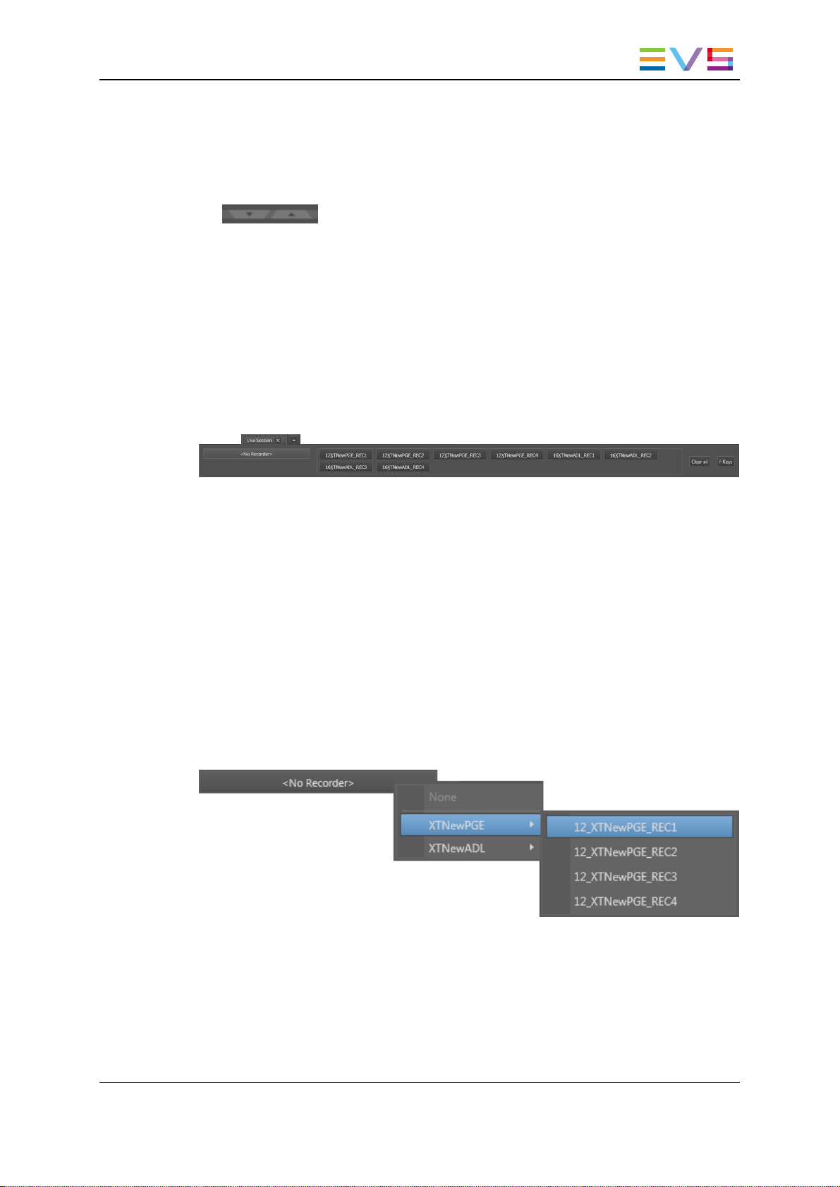
2.2. Recorder Channels Selection Area
Purpose
This area is only available in Live mode.
It displays all the recorder channels from the EVSvideo servers which areavailable on the
XNet network. They correspond to different camera angles.
This area is used to select all the recorder channels from which logs will be relevant when
users log a media, and clips will begenerated.
Selecting the Preview Recorder
The field on the left is used to select the recorder channel which will be set as preview
recorder.
The preview recorder provides the timecode displayedin the Live tab. It will also be the
first angle selected to view an event when an IPDirector operatorloads a log.
To select the preview recorder, right-click the field and select a recorder channel from the
contextual menu:
As soon as a preview recorder has been selected, its name is shown as title tab.
To clear the selection of preview recorder, right-click the Preview Recorder field and
select None.
2. User Interface 7
Page 16

EVS BroadcastEquipment S.A. - April2013 Issue 06.15.B
Selecting the Relevant Recorders
The secondary recorders arethose other camera angles you are interested to log.
To select the relevant recorders, simply click the Recorder Channel button(s). Those
buttons then becomes highlighted.
To clear the selection of relevant recorders, click the Clear All button on the right of the
pane.
2.3. Clips List Pane
2.3.1. Introduction
The Clips List pane is only displayed in Player mode.
It gives the list of clips available from the application. Bins can becreated to organize
clips.
From the Clips List pane, users can search for a clip by different means: by navigating
through the bins in the Treeview, by searchingfor a character string, or by ordering the list
of elements. Results are displayed in the Elements grid of the Clips List.
This pane is thus a central point to perform search on all the clips available and to load
them by a simple operation such as drag-and-drop or double-click.
The whole Clips List pane can behidden or shown in a reducedor enlarged size by
clicking one of the split boxes.
8 2. User Interface
Page 17
IPClipLogger- Version6.15- User Manual
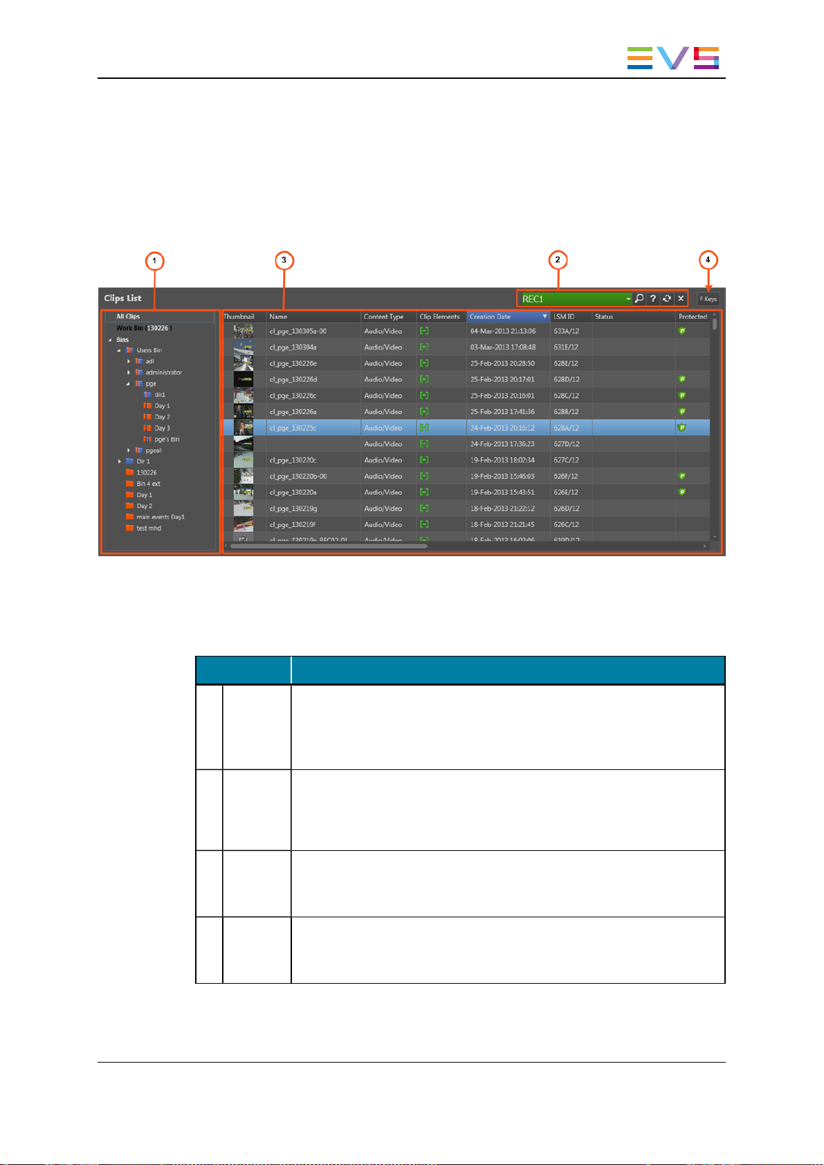
2.3.2. Overview of the Clips List Pane
Illustration
The Clips List pane contains the areas highlighted on the screenshot below:
Area Description
The table below describes the various parts of the Clips List pane:
Area Description
1. Tree
view
2. Quick
Text
Search
area
3. Elements
grid
4. F Keys The F keys option allows to configure shortcuts to easily create a log
The Tree view shows all the clips and bins present in the database and
on the nearline. It also displays the Work bin. The tree branches can be
used to filter items in the Elements grid.
See section "Tree View" on page 10 for details on the interface.
The Quick Text Search area provides functions to perform quick text
searches onthe Elements grid.
See section "Quick Text Search Area" on page 13.
The Elements grid displays all the clips included in the selected tree
branch or resulting from a search.
See section "Elements Grid" on page 14.
with predefined metadata.
See section "Configuring F Keys to Add Logs" on page 73.
2. User Interface 9
Page 18
EVS BroadcastEquipment S.A. - April2013 Issue 06.15.B
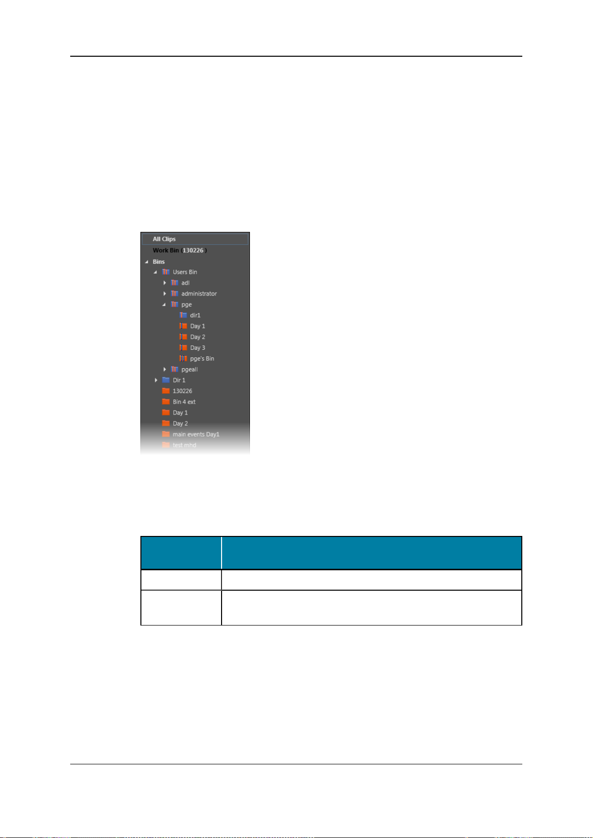
2.3.3. Tree View
Introduction
The Tree view allows browsing andperforming search in the database, among all the clips
or clips present in bins.
Click the arrow next to a tree branch to expand a branch. By browsing the tree structure, a
selection is made anddisplayed in the Elements grid. See section "Branch Selection in
the Tree" on page 42.
Tree View Elements
The table below mentions which items are displayed in the Elements grid basedon the
tree branch selected.
Tree Branch /
Sub-Branch
All Clips Shows all the clips present in the database.
Work Bin
(BinName)
10 2. User Interface
Description
Shows all the clips from the bin set as the user's Work bin.
This branch cannot be expanded.
Page 19
IPClipLogger- Version6.15- User Manual
Tree Branch /
Sub-Branch
Description
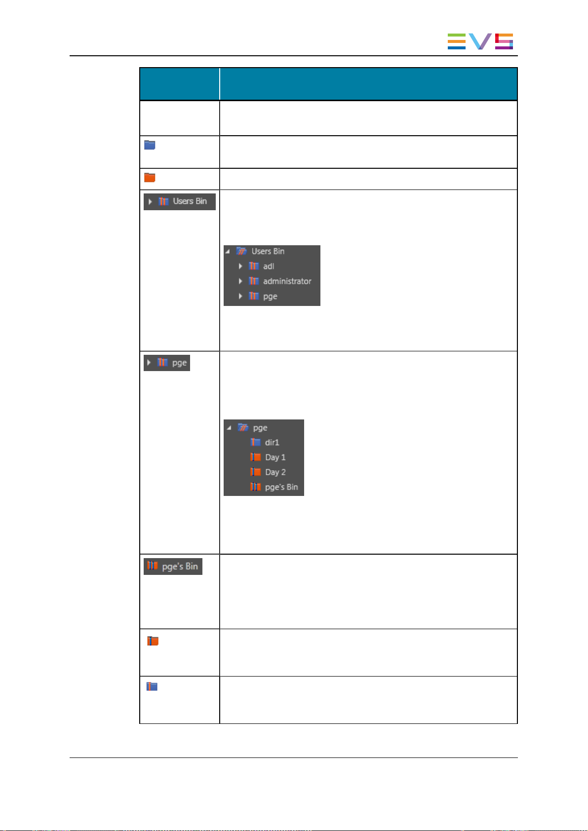
Bins Shows all the clips which are in bins andbin directories.
Expanding the Bins view shows the bins and bin directories.
Bin Directory: shows all the elements which are in all the bins and
directories under the selected directory.
Bin: shows all the elements which are in the selected bin.
Users Bin Directory: shows all the elements which are under all the
System [User] bin directories.
Expanding the Users Bin Directory view displays the System [User]
bin directories for all the users:
This directory is created by the system. It is visible by all the users
but no one can modify, delete or publish it, noradd a bin orbin
directory directly under this directory.
System [User] Bin Directory: shows all the elements which are in
the bins and bin directories for the selected user.
Expanding a System [User] Bin Directory view displays all the bins
andbin directories for the selected user (here: pge). Its name
contains the user logging ID.
This directory is created by the system. It is visible by all the users
but only the ownerof the directory and an administrator can modify,
delete or publish it, oradd a binor bin directory directly under this
directory.
System [User] Bin created by the system for the selected user. Its
name contains the user logging ID.
It shows all the elements put in it by the selected user.
It is visible by all the users but only the owner of the bin and an
administrator can modify, delete orpublish it, or move this bin.
[User] Bin: created by the selected user under its System [User] bin
directory.
It shows all the elements put in it by the selected user.
[User] Bin Directory: created by the selected user under its
System [User] bin directory.
It shows all the elements put in it by the selected user.
2. User Interface 11
Page 20

EVS BroadcastEquipment S.A. - April2013 Issue 06.15.B
Bin Contextual Menu
From the Bins node, different contextual menus can be accessed by right-clicking the
Bins treenode, a bin directory or a bin.
The following table describes all the commands:
Command Description
Set as work bin Sets the selected bin as the Work bin.
Send to Provides a list of possible destination targets to which the
selected bin and its content can be sent.
Backup to
nearline
Publish Opens the Publish window in which you can specify the user
New bin Opens the Create a New Bin window where you can specify the
New directory Opens the Create a New Directory window where you can
Delete selected Deletes the selected bin or directory.
Provides the list of nearlinedestinations to which the selected bin
andits content can be sent.
groups the selected bin orbin directory should be published to.
The bin or bin directory will be published to the selected groups,
providing that they have the adequate rights.
name of the new bin.
This is available from a bin directory or from the Bin node of the
tree view. Not available from a bin nor from the Users bin
directory.
specify the name of the new directory.
This is available from a bin directory or from the Bin node of the
tree view. Not available from a bin nor from the Users bin
directory.
Click Yes in the confirmation window that appears to delete the
bin or bin directory.
This is not available from the Users bin directory, from any
System [user] bin directory, nor from any System [user] bin.
Rename selected Opens a window where you can change the name and
description of the bin or bin directory.
Properties Displays informationrelated to the owner and the groups the
selected bin or directory has been publishedto.
12 2. User Interface
Page 21
IPClipLogger- Version6.15- User Manual
Keyboard Shortcuts
The following shortcuts can be used in the Tree view:
Key Action / Behavior
Up Arrow Select the previous line
Down Arrow Select the next line
Left arrow Collapses the branch
Right Arrow Expands the branch
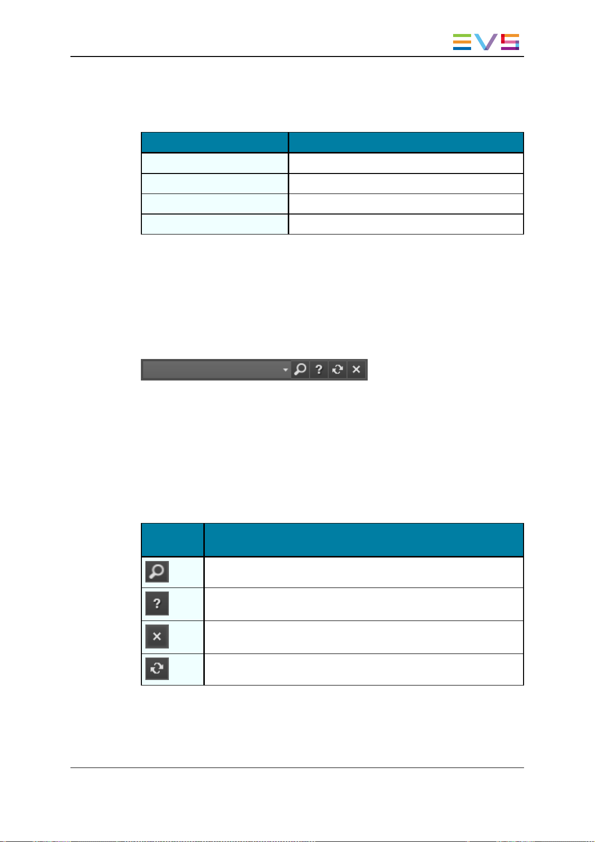
2.3.4. Quick Text Search Area
Introduction
The Quick Text Search is used to perform a search basedon free text entered in the
Quick Text Search field. This field is available on the top of the Elements grid.
The search is performed on the selected treebranch.
See section "Quick Text Search" on page 43 for details on the various ways to use this
function.
Quick Text Search Associated Buttons
The following table gives a descriptionof the buttons located next to the Quick Text
Search field. These buttons may be used not only for the Quick Text Search function but
also for the other search functions in the grid.
Interface
Element
Description
Applies the search againand refreshes the Elements grid.
Displays the Syntax Rules list. See section "Quick Text Search Syntax
Rules" on page 44.
Clears the applied Quick Text search.
Refreshes the entire interface.
2. User Interface 13
Page 22
EVS BroadcastEquipment S.A. - April2013 Issue 06.15.B
2.3.5. Elements Grid
Introduction
The Elements grid represents the content of the tree branch selected in the Tree view. XT
clips andfiles are displayed for the All Clips and the Bins branches. The Clips branch
also lists the recordtrains from the servers present on the XNet. They appear with the
same icon as an XT high resolution clip.
It also returns the result of a search appliedto a selected branch of the Tree view.
A thumbnail can be displayed for each element if this has been set by the administrator.
In the grid, elements are presented in rows and all their associated parameters and
metadata are in columns.
Clip Element Types
A clip is a logical entity that contains A/V media and can include several physical
resources (clips and/or files).
A clip element is the physical resource inside the clip: XT clip or nearline file.
A clip and its clip elements sharethe same TC IN, TC OUTand metadata set.
A clip can contain up to six types of clip elements and each of them is identified in the
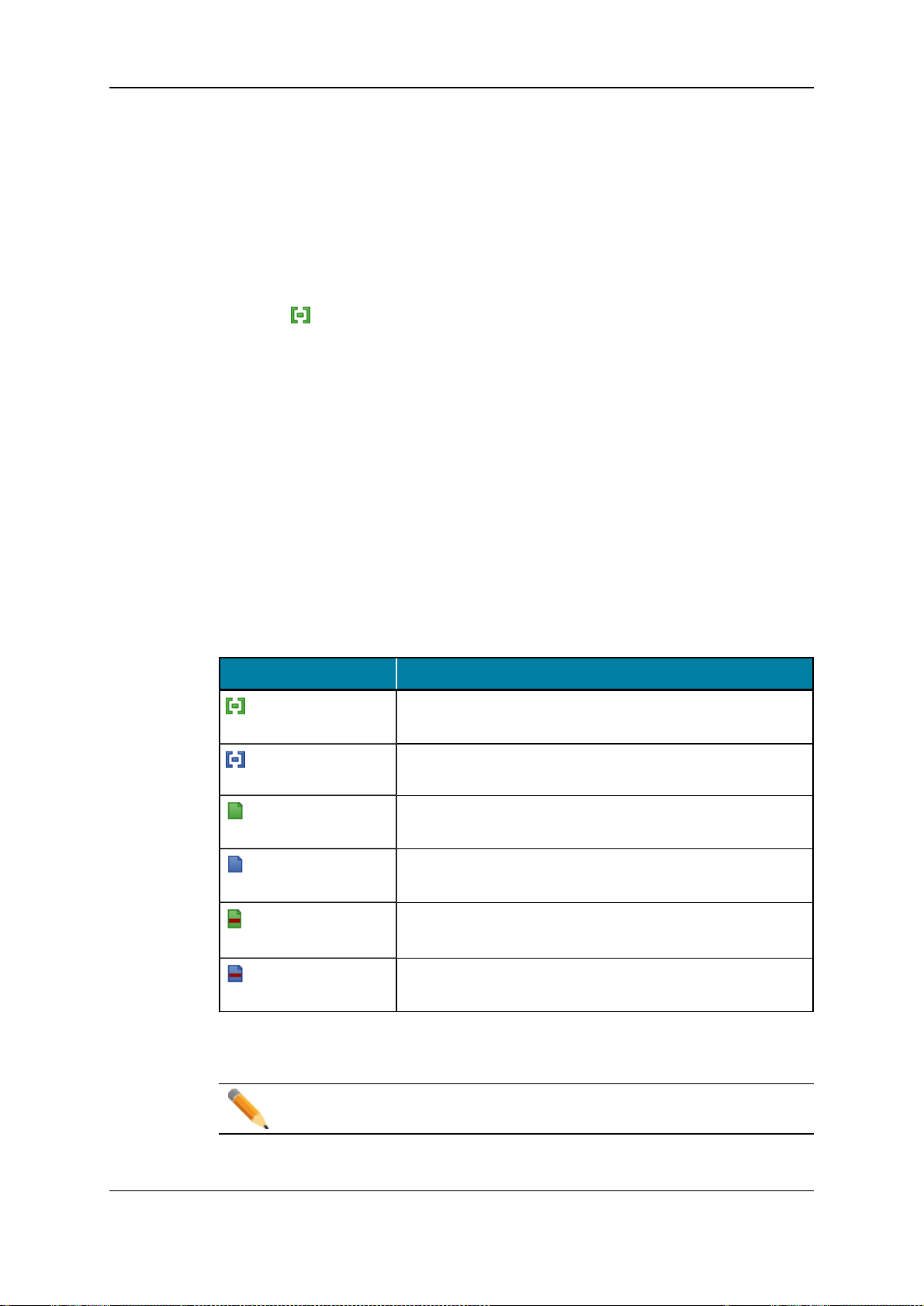
Elements grid by a distinct icon, as detailed in the table below.
Clip Element Description
XT high resolution
clip
XT low resolutionclip
on-line high
resolution nearline file
on-line low resolution
nearline file
off-line high
resolution nearline file
off-line low resolution
nearline file
highresolution clip or growing clip stored on an EVS video
server.
low resolution clip or growing clip stored on an EVS video
server.
highresolution file stored in nearline folders, IP drive is online (accessible and managed).
low resolution files stored in nearline folders, IP drive is online (accessible and managed).
highresolution files stored in nearline folders, IP drive is no
more on-line.
low resolution files stored in nearline folders, IP drive is no
more on-line.
In the Elements grid, the Clip Elements column shows the icons for the different clip
elements making up the clip.
Note
There can be several copies of the same element within a clip.
14 2. User Interface
Page 23
IPClipLogger- Version6.15- User Manual
Elements Grid Header Contextual Menu
Right-clicking the gridheader displays the grid contextual menu.
The options are described in the following table:
Option Description
Hide Hides the selected column.
Organize The Select Columns window opens and allows the selection of columns
to display andin which order.
Save grid
organization
Reset grid
organization
Saves the organization of the grid as it is displayed (columns selection,
order and size). It is saved by each user. Therefore, this organization
will be retained the next time the user logs in and opens the application.
Returns the grid to the default grid organization.
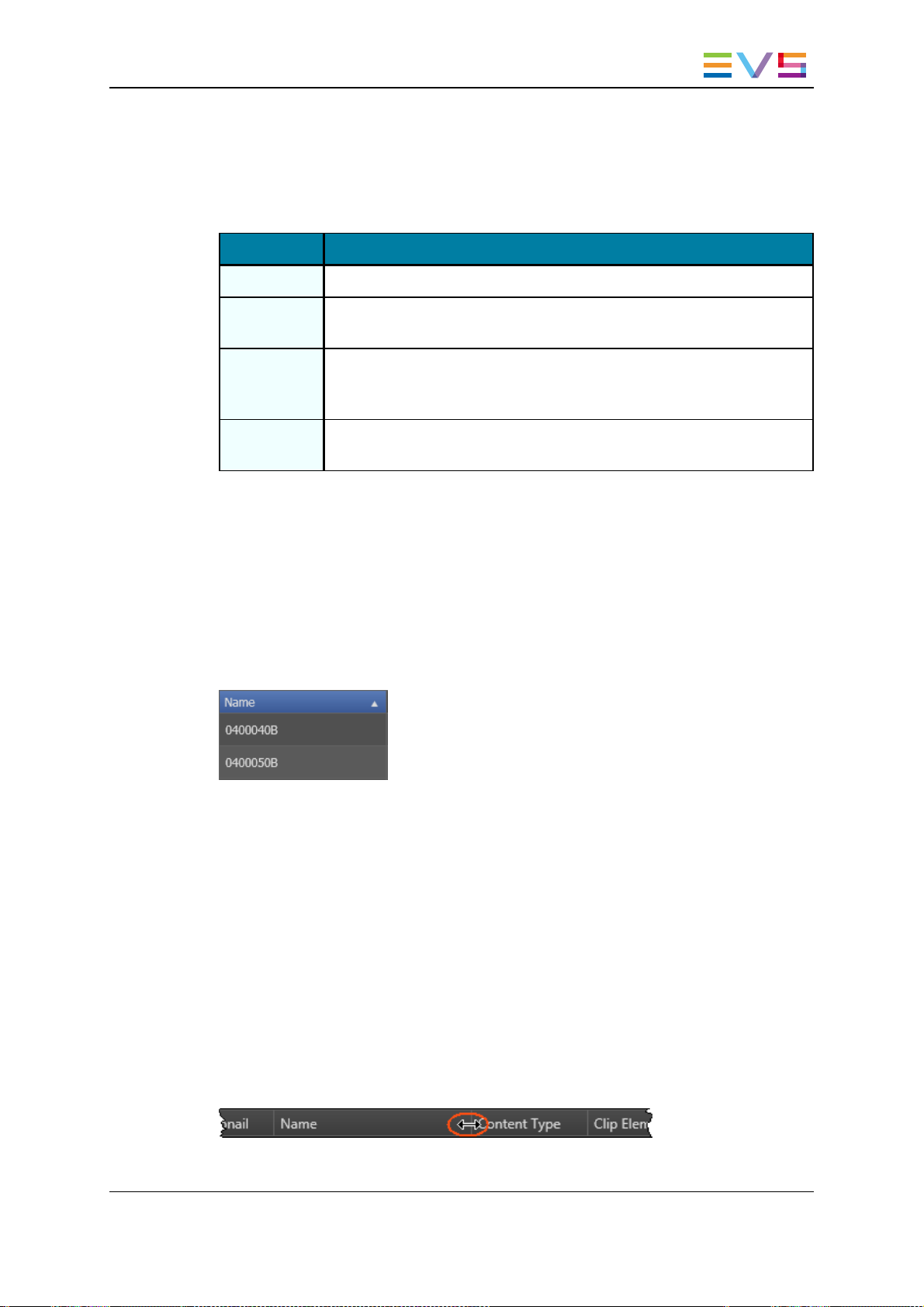
Sorting the Elements in the Grid
At start of the application, items are sorted with most recent on top.
You can change the sort orderof elements in the grid by clicking the column header for the
parameter according to which you want to sort the elements.
The column header which is used for sorting is highlighted in blue. The little triangle
indicates the sorting order. Clicking the column headeragain changes the sorting order
from ascending to descending or vice versa.
Organizing Columns
Possible Actions
Columns can be resized and/or re-ordered. This new organization is automatically saved
andremembered. However, it is possible to reset the column organization to the default
organization.
Resizing Columns
A columncan be resized by using the mouse pointer over columns intersection and
dragging it to the right or to the left.
2. User Interface 15
Page 24

EVS BroadcastEquipment S.A. - April2013 Issue 06.15.B
Selecting Columns to Display
To select the columns to display in the grid, proceed as follows:
1. Right-click the column header area.
A menu is displayed.
2. Select Organize.
The Select Columns window opens and shows the list of columns in the current order.
3. To select the column(s) you wish to add to the view, do one of the following:
◦ in the left pane, double-click the column(s) you wish to add to the view
◦ select them in the left pane and click the right blue arrow
◦ drag them onto the Visible Columns area.
Use CTRL + click to select multiple columns.
Use SHIFT + click to select a rangeof columns.
4. To select the column(s) you wish to remove from the view, do oneof the following:
◦ on the right pane, double-click the column(s) you wish to remove from the view
◦ select them in the Visible Columns area on the right pane and click the left blue
arrow
◦ drag them onto the left pane.
Use CTRL + click to select multiple columns.
Use SHIFT + click to select a rangeof columns.
5. Click OK to confirm the changes.
Ordering Columns
To change the columns order, proceed in oneof the following ways.
Select a column headerand drag it to the left or right to the requiredplace:
OR
1. Right-click a columnheader.
A menu is displayed.
2. Select Organize.
The Select Columns window opens and shows the list of columns in the current order.
3. Drag the selected columnto the required position in the Visible Columns pane.
4. Click OK to confirm the changes.
16 2. User Interface
Page 25

IPClipLogger- Version6.15- User Manual
Resetting the Column Organization to the Default One
To reset the column organization to the default one, proceed as follows:
1. Right-click the column headers area.
2. Select Reset Grid Organization.
Clip Contextual Menu
The Clip contextual menu is available whenright-clicking a clip in the Elements grid. It
gives access to the actions that can be performed on clips.
Note
No contextual menu is available from a record train.
The following table describes the commands from the Clip contextual menu:
Command Description
Cut Not relevant in the Elements grid.
Copy Copies the clip to the clipboard. A shortcut to the clip can thenbe pasted in
a bin.
Paste Not relevant in the Elements grid.
Send To Provides a list of possible destinations to which the selected clip can be
sent.
Possible destinations are:
• the user's default bin
• the user's default playlist
• a default archive target
• any target destination visible on the GigE network that has been
defined, such as CleanEdit targets, Avid targets, Final Cut Pro
targets, File targets, EVS servers targets.
Backup to
Nearline
Enables the backup of clip to the default nearline or to a nearline directory.
Lists the on-line nearline directories destinations to which the loaded clip
can be sent.
Duringthe backup process, an XML metadata file is generated. In this file,
the keywords assigned to the clip appear in the order they have been
entered by the operator.
Copy by
GigE
2. User Interface 17
Copies a clip from an EVS videoserver to another one by the way of the
Gigabit network, as long as the servers have an operational GigE
connection. This menu lists all the EVS video servers that have a GigE
address with sub-menus to select server pages.
Page 26
EVS BroadcastEquipment S.A. - April2013 Issue 06.15.B
Command Description
Restore toXTRestores the clip to an EVS video server:
• the default server.
The default server is defined in the XNet network page of the Remote
Installer.
• oneof the EVS video servers with GigE address present on the
network.
A submenu is available from each EVS video server to select the
server page whereyou can restore the clip.
Publish Opens the Publish window from which the selected clip can be published,
i.e. made available to selected groups of users.
Delete Allows the deletion of the selected clip.
This option is not available if the clip is part of a playlist orif it is currently
loaded on a player channel of an EVS video server.
When this optionis selected from the Bins view, it deletes the selected
clip from the bin and from the actual clip location.
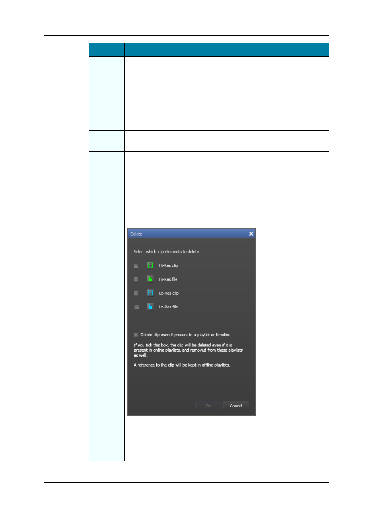
Delete
Selected
Clip
Elements
This option is only visible by high-low browsers.
The Delete window is thendisplayed and allows you to select the clip
elements to delete.
View Key
This option is unavailable.
Clip
Edit Opens the Edit Clip window, similar to the Save Clip window, from which
the user can modify the clip information.
18 2. User Interface
Page 27

IPClipLogger- Version6.15- User Manual
Command Description
Modify
T/C IN or
Date
Generate
XML
Metadata
Protect Allows you to protect or unprotect a clip from deletion:
Unprotect Allows you to unprotect the selected clip when it has been protected from
Duplicate Opens the Duplicate Clip window where you can specify the location on
Move Opens the Move Clip window where you can specify the location on an
Opens the Modify T/C In or Date window from which the usercan modify
the IN timecode or the date of the clip.
The XML file is synchronizedfor the selected clip, provided that the
IPDirector workstation has been configured as master. With workstations
configuredas slave, an error message is displayed when using this option.
• A Protect icon appears in the Protect column of the Elements grid
when the clip is protected.
• A message will warnthe IPDirector users or the Multicam users who
would try to delete the clip.
IPDirector (or IPClipLogger).
an EVS video server of the XNet Network where the copy of the clip must
be stored.
Files are not duplicated.
EVS video server of the XNet Network where the clip must be moved.
This command is not available for files.
Link Allows you to link selected clips manually. It is only possible to link clips
that are not already associated with otherclips.
Unlink Allows you to unlink the clips linkedto the selected clips.
Properties Displays information related to the ownerand the groups the selected clip
has beenpublished to.
Operations Allowed from the Elements Grid
Besides the actions available from the Clip contextual menu, the following operations are
possible from the Elements grid:
Operation Resulting action
Click on anelement line Simply selects the element.
Double-click or press Enter on an element
line
Loads the element on the Player pane.
See section "Loading Media" on page
49
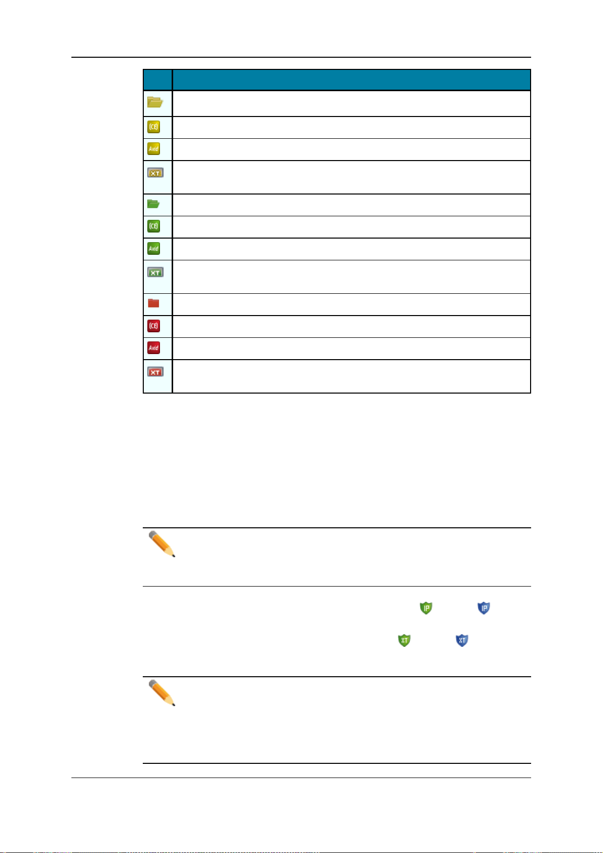
Transfer Status Icons
The Status column of the Elements grid gives informationon the transfer status of the
selected clip.The table below gives the meaning for most of the icons which can appearin
this column.
2. User Interface 19
Page 28
EVS BroadcastEquipment S.A. - April2013 Issue 06.15.B
Icon Description
The clip is still in the process of being sent to a nearline/target.
The clip is still in the process of being sent to CleanEdit application.
The clip is still in the process of being sent to Avid.
The clip is still in the process of being sent to an EVS video server through the
GigE network.
The clip has been successfully sent to a nearline/target.
The clip has been successfully sent to CleanEdit application.
The clip has been successfully sent to Avid.
The clip has been successfully sent to an EVS video server through the GigE
network.
Clip for which the transfer to a nearline/target failed.
Clip for which the transfer to CleanEdit application failed.
Clip for which the transfer to Avid failed.
Clip for which the transfer to an EVS video server through the GigE network
failed.
Clip Protection
Clips can be protected by Multicam users or otherIPDirector (or IPClipLogger) users. The
clip protection will not prevent other users from deleting the clips. However, it will warn
them that the clip is protected and shouldnot be deleted.
Within IPDirector (or IPClipLogger), you can protect and unprotect a clip mainly from the
contextual menus or during the creation of a clip.
Note
When you protect a XT hi-res clip, the lo-res version (if present) is protected
automatically andvice versa. Then, two icons will be displayed, one for each XT
clip. The protect feature does not affect hi-res or lo-res files.
If a clip is protected by the IPDirector protocol, the Protect icon (hi-res) or (lo-res)
appears in the Protect column of the element.
If the clip is protected by another protocol, the Protect icon (hi-res) or (lo-res)
appears in the Protect column.
Note
It is possible to protect a clip via IPDirector if it is already protected by another
protocol. This will ensure that the clip remains protected even if it is unprotected
later by the other protocol.
From IPDirector, it is not possible to remove the clip protection defined by
another protocol.
20 2. User Interface
Page 29

IPClipLogger- Version6.15- User Manual
2.4. Clip Infos Pane
2.4.1. Purpose
In both Live andPlayer modes, the Clip Infos pane is used to create a clip and to enterclip
metadata for the clip being created. In Player mode, the associated Player paneis used to
view the media to belogged and to browse the media. When an existing clip is loaded on
the Player pane, the Clip Infos pane displays the clip metadata.
2.4.2. Overview of the Clip Infos Pane
Introduction
The layout of the Clip Infos pane slightly differs between the Player Session tab and a
Live Session tab.
2. User Interface 21
Page 30

EVS BroadcastEquipment S.A. - April2013 Issue 06.15.B
Illustration
Player Session Tab
The Clip Infos pane of the Player Session tab contains the areas highlighted on the
screenshot below:
22 2. User Interface
Page 31

IPClipLogger- Version6.15- User Manual
Live Session Tab
The Clip Infos pane of a Live Session tab contains the areas highlighted on the screenshot
below:
Area Description
The table below describes the various parts of the Clip Infos pane:
2. User Interface 23
Page 32

EVS BroadcastEquipment S.A. - April2013 Issue 06.15.B
Area Description
1. Current
Timecode
field
This field provides the current timecode of the loaded media. See
section "Timecode Fields Display" on page 25.
In Player mode, it allows to jump to a specific timecode. See
section "Jumping to a Given Timecode within the LoadedMedia"
on page 61.
2-5 Player pane The Player pane is only displayed in the Player Session tab.
2. Video
Display and
Audiometers
This area displays the media loadedon the Player.
See section "Video Display" on page 25.
It may also show audiometers for audio monitoring.
See section "Audio Level Monitoring" onpage 27.
3. Jog bar The jog bar allows you to move within the media at a variable
speed. See section "Jog Bar" on page 28.
4. Transport
commands
Those commands are used to load, browse in and play the loaded
media.
See section "General Transport Buttons andShortcuts" on page
58 for the list of transport buttons, shortcuts and ShuttlePro keys.
The E/E function and the Ret function are described in section
"Loading a Train or a Recording Ingest in Player Mode" on page
51.
5. Maximize
button
6. Clip Creation
commands
This button is used to maximize the player on a second screen.
See section "Player Full Screen Mode" on page 29.
Those commands are used to create a clip from the loaded media.
See section "Clip Creation Buttons and Shortcuts" on page 64 for
the list of clip creation buttons, shortcuts and ShuttlePro keys.
It also displays the timecode of the INpoint, next to the INbutton,
andthe timecode of the OUTpoint, next to the OUTbutton.
7. Clip name Free text field used to enter a name for the clip being created.
8. General
information
This area can be used to associate an interest level to the clip or to
enter a reference for a tape ID.
See section "Interest Level Buttons" on page 29.
9. Keywords This area allows the selection of keywords to associate to the clip.
See section "Assigning Keywords to Media" on page 82.
They will appearin the Keywords and/or the Participants
columns of the Elements grid for the corresponding clip. When
logs will be created for the clip, those keywords will also appear in
the Parent Keywords and/or the Parent Participants columns of
the Logs grid.
10. Metadata
Profiles
This area can be used to associate a metadata profile to the clip.
Doing this, all the user fields which make upthe metadata profile
appear and can be filled in by users.
See section "Metadata Profiles" on page 30.
24 2. User Interface
Page 33

IPClipLogger- Version6.15- User Manual
The General, Keywords and Metadata Profiles areas can be expanded, or collapsed, by
clicking the arrow at the beginning of each section.
2.4.3. Timecode Fields Display
Information displayed in the Current Timecode field and in the Clip INand Clip OUT
fields can be changed as follows:
1. Right-click the Timecode field.
A contextual menu with following options is displayed:
◦ Timecode
◦ Timecode and date
◦ Timecode and date and TC type
◦ Timecode and TC type
2. Select one of the options.
3. When the TC type is displayed, right-clicking it in the Timecode field allows to shift
from one TCtype to the other (LTC or user).
4. When the date is displayed, clicking it in the Timecode field opens a calendar for date
selection.
2.4.4. Video Display
Video Display
The background of the Player pane is gray whenno media is loaded or when the loaded
media contains anon-line hi-res element.
The background of the Player pane is red when the loadedmedia does not contain an online hi-res element.
Video Display Contextual Menu
A contextual menu is accessible by right-clicking the Video Display of the Playerpane
when a media is loaded. It gives access to audioparameters. See section "Audio
Configurationand Monitoring" on page 26 for more information.
2. User Interface 25
Page 34

EVS BroadcastEquipment S.A. - April2013 Issue 06.15.B
2.4.5. Audio Configuration and Monitoring
Audio Configuration
To select the audio channels you want to listen to, proceed as follows:
1. Right-click the Video Display.
2. Select OCX Audio Configuration from the contextual menu.
The Audio Output Channels window opens:
3. On the Left line, click the cell corresponding to the channel you want to associate to
the left ear.
4. On the Right line, click the cell corresponding to the channel you want to associate to
the right ear.
5. If required, adjust the input gain.
26 2. User Interface
Page 35

IPClipLogger- Version6.15- User Manual
6. For an easy retrieval of the configuration, you can save it:
◦ Enter a name in the Template Name field
◦ Click the Add button.
7. Click OK.
The audio configuration is automatically applied.
Audio Level Monitoring
The audio level can be monitored with audiometers on the sides of the Video Display.
To select the number of audio channels to be displayed, proceed as follows:
1. Right-click the Video Display.
2. Select OCX Audio Configuration from the contextual menu.
The Audio Output Channels window opens.
3. Click the radiobutton corresponding to the number of audiochannels to display.
The audiometers are shown on the Video Display sides.
• Example for a selection of 2 channels:
• Example for a selection of 16channels:
2. User Interface 27
Page 36

EVS BroadcastEquipment S.A. - April2013 Issue 06.15.B
2.4.6. Jog Bar
The jog bar display differs accordingto the loadedelement.
Clip
When a clip is loaded, the jog bar is a graphical representation of its duration and its
guardbands.
• The bluesections represent the guardbands before the IN point and after the OUT
point.
• The gray section between the guardbands represents the clip length, between the IN
point and the OUT point.
• The bullet indicator shows the current relative position in the clip.
Train
When a local train is loaded, only the gray section is displayed:
Recording Ingest
When an ingest being recorded is loaded, the bullet indicatorcannot be moved further
to the right than the current timecode position being recorded.
Log
When a log is loaded, the bullet indicator stands on the log timecode.
Clip being Created
When a clip is being created, the following indicators appear :
• A greenposition indicator is shown when the IN button has been clicked and
represents the temporary IN point position until the UPDATE CLIP button or the
SAVE CLIP button is clicked.
• A red position indicator is shown when the OUT button has been clicked and
represents the temporary OUT point position until the UPDATE CLIP button or the
SAVE CLIP button is clicked.
28 2. User Interface
Page 37

IPClipLogger- Version6.15- User Manual
2.4.7. Player Full Screen Mode
The Maximize button , or the keyboardshortcut, puts the Player pane in full-
screen mode.
The Video Display moves on a second screen. All the otheruser interface elements from
the Player pane stay on the initial screen.
Shortcuts remain usable. Controls appear at the bottom of the screen when keeping the
mouse overthe area.
This mode can thenbe exited by clicking the Maximize button again or by pressing the
Escape key.
2.4.8. Interest Level Buttons
The Interest Level buttons allow users to assign an interest rating to a clip. Four interest
levels can be defined, from nostar to 3 stars. The backgroundof the button corresponding
to the selected interest level is blue. Thedefault value is the no star level.
2. User Interface 29
Page 38

EVS BroadcastEquipment S.A. - April2013 Issue 06.15.B
2.4.9. Metadata Profiles
Purpose
A metadata profile is made of a set of user fields which aremanaged together.
Metadata profiles are createdin IPDirector. IPClipLogger users may only select one of the
metadata profiles that they are allowed to use from the Current Profile list.
At clip creation, as soon as a metadata profile is selected in the Clip Infos pane, all the
user fields composing the profile are displayedand users can enterspecific values for
each of them.
Then, columns dedicated to the userfields headings can be displayed in the Elements grid
anduser fields values can beused in searches with the Quick Text Search.
Possible Types of User Fields
Several types of user fields can have beendefined at the metadata profile creation.
All the types of user fields are listed hereafter with the way they appear in the element
metadata area.
Text (64 characters)
The Text user field type will appear on screen as a free-text field:
30 2. User Interface
Page 39

IPClipLogger- Version6.15- User Manual
Memo (text, unlimited number of characters)
The Memo user field type will appear on screen as a free-text field:
TC (for Timecode)
The TC user field type will appear on screen as a timecode field:
Date
The Date user field type will appear on screen as a Date field with a Calendar button
giving access to a calendar:
Number
The Number user field type will appear on screen as a field with upand down arrows to
increase or decrease the value.
2. User Interface 31
Page 40

EVS BroadcastEquipment S.A. - April2013 Issue 06.15.B
Predefined Text Values (64 characters)
The Predefined Text values user field type will appear on screen as a drop-down list
displayingall the values which have been created for the user field:
A + button displayed on the right of the combo box allows you to add additional values in
the list of predefined values.
2.5. Logs Panes
2.5.1. Purpose
The Logging pane is usedto create logs on a loaded media and to associate metadata to
them.
The Associated Logs pane displays the list of logs for a loaded clip or for the clip being
logged andprovides a Quick Text Search area to filter the logs.
Both panes are identical in a Live Session tab and in the Player Session tab.
32 2. User Interface
Page 41

IPClipLogger- Version6.15- User Manual
2.5.2. Overview of the Logging Pane
Illustration
The Logging pane contains the areas highlighted on the screenshot below:
2. User Interface 33
Page 42

EVS BroadcastEquipment S.A. - April2013 Issue 06.15.B
Area Description
The table below describes the various parts of the Logging pane:
Area Description
1. Log
Sheet
name
2. Log
Creation
buttons
3. LogInfo
area
This area displays the nameof the log sheet associated to a clip which
contains saved logs.
See sections "Live Logging" on page 75 and "Retroactive Logging" on
page 78.
Those commands are used to create a log on the loadedmedia.
See section "LogCreation Buttons and Shortcuts" on page73 for the list
of log creation buttons and shortcuts.
The LogInfo area is used to add keywords, a description, an interest
level and a colorto each log. It contains the Log Timecode field which
shows the timecode of the current log.
See section "LogInfo" on page35.
2.5.3. Overview of the Associated Logs Pane
Illustration
The Associated Logs pane contains the areas highlighted on the screenshot below:
34 2. User Interface
Page 43

IPClipLogger- Version6.15- User Manual
Area Description
The table below describes the various parts of the Associated Logs pane:
Area Description
1. Logs
grid
2. Quick
Text
Search
area
2.5.4. Log Info
The table below describes all the fields and buttons displayed in the Log Info area. They
relate to a logbeing created or to the log loadedon the Player pane.
User Interface
Element
Log Timecode This read-only field displays the log timecode of the current log. It is
The Logs grid lists all the logs associated to the clip loaded on the Player
pane or to the clip being created in the Player or Live tab.
See section "Logs Grid" on page 36.
The Quick Text Search area provides functions to perform quick text
searches in the Logs grid. Its use and its associatedbuttons are similar
to the Quick Text Search areaof the Elements grid.
See section "Quick Text Search Area" on page 13.
Description
grabbed from the preview recorder in a Live session or the loaded train
or clip in the Playersession.
The timecode display can be changed by right-clicking this field and
selecting an option from the menu. See section "Timecode Fields
Display" on page 25.
Description This field is used to add a freetext description to the log.
This will appear in the Description columnof the Logs grid for the
corresponding log.
Switch
ENTER /
CTRL+ENTER
Interest Level These buttons are used to assign an interest rating to the log. Four
This option determines the behavior of the ENTER shortcut and the
CTRL+ENTERshortcut.
When the checkbox is selected:
• ENTERvalidates the log
• CTRL+ENTER goes to the next line in the Description field.
When the option is not selected, the behavior of the two shortcuts is
reversed.
interest levels can be defined, from no star to 3 stars. The background
of the button correspondingto the selected interest level is blue. The
default valueis the no star level.
2. User Interface 35
Page 44

EVS BroadcastEquipment S.A. - April2013 Issue 06.15.B
User Interface
Element
Highlight
Colors
Keywords This area allows the selection of keywords to associate to the log. Up
Follow
Previous Logs
Keywords
checkbox
2.5.5. Logs Grid
Description
These buttons are a set of colors which can beused to categorize the
logs. The gray button lets the log without any associated color. The
log line will be highlighted with the selected colorin the Logs grid and
the Elements grid. The operator can then search on the colors in the
grids.
to 10 keywords can be added per log.
See section "Assigning Keywords to Media" on page 82 for more
information on how to assign keywords to media.
They will appearin the Keywords and/or the Participants columns of
the grid for the corresponding log.
This checkbox is used to keepselected keywords from one log to
another. When the checkbox is selected, the keywords entered for a
log are automatically kept for the next logcreated.
The Logs grid represents the list of saved logs for the clip loaded on the Player pane or for
the clip being created.
Logs are presented in rows and all their associated parameters and metadata are in
columns. They are highlighted with the color which has been associated to them at
creation. A thumbnail can be displayed for each log if this has been set by the
administrator.
The display of the Logs grid is managedin the same way as the Elements grid is. Users
can display, hide, resize or re-ordercolumns, and sort the logs in the grid. See section
"Elements Grid" on page 14 for a description of all those operations.
2.6. Keywords Grids
2.6.1. Purpose
The Keywords Grid pane is a tool used to assign keywords to clips and logs.
Keyword grids are created in IPDirector. IPClipLogger users may display one or several of
them but cannot manage the addition, update or deletionof keywords in grids.
The Keywords Grid pane is displayed by clicking the Keywords Grid button in the Player
Session tab orin a Live Session tab. The button background then becomes blue.
36 2. User Interface
Page 45

IPClipLogger- Version6.15- User Manual
When a new logging session is open, the keyword grids displayed are the same as those
from the first tab. Afterwards, keywords grids from the different tabs can evolve
independently.
The Keywords Grid pane can be hidden by clicking the Keywords Grid button again.
See section "Assigning a Keyword from a Keyword Grid" on page 84 for a description of
the procedure to follow to use keyword grids for the additionor deletion of keyword(s) to a
clip ora log.
2.6.2. Overview of the Keywords Grid Pane
Illustration
The Keywords Grid pane contains the areas highlighted on the screenshot below:
2. User Interface 37
Page 46

EVS BroadcastEquipment S.A. - April2013 Issue 06.15.B
Area Description
The table below describes the various parts of the Keywords Grid pane:
Area Description
1. Keyword
Grid
Mode
icon
This icon displays either or depending on the pane
currently active: Clip for the Clip Infos pane, Log for the Loggingpane.
So, it gives indication on the element the keyword will beassigned to.
2. Keyword
Grids List
field
3. Add Grid
button
4. Keywords
grid(s)
5. Remove
Grid
button
This field gives the list of available keyword grids. It allows the
selection of the keyword grid to be displayed.
This button is used to display the keyword grid just selected in the
Keyword Grids List field.
This area displays the keyword grid(s) selected in the Keyword Grids
List field.
Keywords may be highlighted in a different color. The backgroundand
foreground colors of a keyword areset within IPDirector andcannot be
changed from IPClipLogger.
As soon as a keyword is assigned to a clip or log, it is displayed on a
dark blue background:
This button is used to hide the corresponding keyword grid.
2.6.3. Keyword Types
A distinction can bemade between standardkeywords and participant keywords. The
participant keywords can be used for the competitor or player names. The standard
keywords can be usedfor actions.
By default, the keywords are definedas standard keywords.
The participant keywords are differentiated by a little blue icon next to the keyword in the
keyword grids.
38 2. User Interface
Page 47

IPClipLogger- Version6.15- User Manual
2.7. Message Pane
2.7.1. Purpose
The Message field displays the most recent message.
The Message panel expands by clicking the arrow on the right of the Message field. It
provides a quick display of the information, warning anderror messages generatedduring
the current session.
2.7.2. Messages Display
The messages includethe followinginformation:
• the date and time whenthe message was generated
• the message itself
The messages are highlighted on a different background colordepending on the type of
message.
• An informationmessage is highlighted in green.
• A warning message is highlighted in orange.
• An error message is highlighted in red.
2.7.3. Message Acknowledgment
As soon as a message appears, the Acknowledge button turns red.
→
Users can acknowledge the message by clicking the button. This changes the
background of the message to gray.
This helps the users to distinguish the messages that have been dealt with from the ones
that have not.
2. User Interface 39
Page 48

EVS BroadcastEquipment S.A. - April2013 Issue 06.15.B
2.7.4. Messages Filter
Messages can be filtered according to their type thanks to the Message Type buttons
displayed on the top left cornerof the expanded Message field: Information, Warning,
Error.
By default, all the filters are enabled and all the buttons have a blue background.
To disable a filter and remove the corresponding messages from the list, users must click
the Message Type button for that filter. The button is then displayed on a gray
background.
40 2. User Interface
Page 49

IPClipLogger- Version6.15- User Manual
3. Working with Multiple Logging Sessions
3.1. Introduction
On some occasions, users work on several events at the same time and needto have
more than one logging session at theirdisposal. TheIPClipLogger is able to managethis
case and offers the possibility to open up to five tabs from which it is easy to switch.
The first time the application is opened, two tabs are shown. Thefirst tab always displays
a session in Playermode and cannot be closed. The second tab is dedicatedto a Live
session and can beclosed.
All the other tabs that users would create areautomatically set to work in Live mode.
Each logging session is completely independent of the otherones. This means that there
is no interaction on the work performed on each of them.
3.2. Managing Several Logging Sessions
To opena new logging session, press the + keys or click the + button on
the right of the tabs series.
A new tab is displayed, entitled Live Session. As soon as a main recorder channel has
been selected, its name is shown as tab title.
Users can then perform some actions in one tab, switch to another tab, perform actions in
the second tab, and switch back to the first tab without losing any work done in any tab.
When a new logging session is open, the keyword grids displayed are the same as those
from the first tab. Afterwards, keywords grids from the different tabs can evolve
independently.
To close a logging session, press the + keys orclick the X button next to
the corresponding tab. The Player Session tab cannot be closed.
3. Working with Multiple Logging Sessions 41
Page 50

EVS BroadcastEquipment S.A. - April2013 Issue 06.15.B
4. Searching for Media
4.1. Search Types
Search in the Elements Grid
When the database contains large amounts of data, it may become difficult to find a
specific element. TheIPClipLogger offers several ways to restrict the list of elements
displayed in the Element grid and speed up your search:
• Branch selection in the Tree view - Select a branch of the Tree view to limit the list to
some item types.
• Quick text search - Enter free text in the Quick Text Search field to perform a search
on a specific string.
• Advancedsearch filter – specific criteria to perform a search on a specific metadata of
the elements.
All these search tools can be combined.
An applied filter can be saved for later use. Such a saved filter can then be applied in one
click.
A search can also be facilitated by ordering the Elements grid. See section "Elements
Grid" on page 14 for more information.
Search in the Logs Grid
The Associated Logs pane also provides a simplifiedQuick Text Search area to filter the
logs displayed in the Associated Logs pane.
4.2. Branch Selection in the Tree
The Tree view allows browsing andperforming search in the database and the nearline,
among all the clips or clips present in bins. By browsing the treestructure, a selection is
made and displayed in the Element grid.
If a Quick Text search has beenappliedto a branch andnot cleared, the filter is
remembered when this branch is selected again.
See section "Tree View" on page 10 for a description of the user interface elements of the
Tree view.
42 4. Searching for Media
Page 51

IPClipLogger- Version6.15- User Manual
4.3. Quick Text Search
4.3.1. Purpose and Context of Use
The Quick Text Search function is used to perform a search based on free text entered in
the Quick Text Search field. This field is availableon the top of the Elements grid:
The Associated Logs pane also provides a simplifiedQuick Text Search area to filter the
logs displayed in the Associated Logs pane:
See section "Quick Text Search Associated Buttons" on page 13 for the description of the
buttons associated to the Quick Text Search field.
The columns that are taken into account for the Quick Text Search are the ones currently
visible in the Elements grid. The search is performed on the branch selected in the Tree
view.
The filter remains applied until it is clearedwith the Clear button of the Quick Text Search
area.
Users can enter a search string in one of the following ways.
• They enterthe search string in full in the Quick Text Search field.
• They click the arrow next to the Quick Text Search field, so the last 10 searches are
displayed, and they select one of them. See section "Quick Text Search Field
Display" on page 44.
• They start typing a search string in the Quick Text Search field, so the Autocomplete
function displays a list of proposals, and they can select oneof them. See section
"Autocomplete Function in Quick Text Search Field" on page 45.
4.3.2. Search for Synonyms
Users have the possibility to perform a search for word synonyms, provided that they
have been definedin the SQL thesaurus file and that the corresponding option has been
set in the IPDirector General setting Freetext searches behavior.
Then, a search performed with a search string will return the predefined synonyms as
well. This function can be used to search for translated words.
4. Searching for Media 43
Page 52

EVS BroadcastEquipment S.A. - April2013 Issue 06.15.B
4.3.3. Quick Text Search Field Display
The following table shows the various displays for the Quick Text Search field, and what
they mean:
Display Meaning
The field background is gray:
No Quick Text Search is appliednor entered.
The field background is red:
The user is typing or has typed a search string, but
has not applied it yet, ora search has been applied
but the user has typed another search string in the
field and not applied it yet.
The field background is green:
The user has applied the search string, by pressing
ENTER. The result of the Quick Text Search is
displayed in the grid.
The down arrow next to the Quick Text Search field
gives access to the last 10 searched strings.
4.3.4. Quick Text Search Syntax Rules
The Quick Text Search optionobeys specific rules which can be accessed via the Help
button next to the Quick Text Search field: .
44 4. Searching for Media
Page 53

IPClipLogger- Version6.15- User Manual
The string that you enter in the Quick Text Search field is analyzed according to the
following set of rules:
Search String Search Result Logical Equivalent
Yellow card Searches for the words yellow andcard, evenif
in two different fields (columns), for example
yellow in Name and card in Keywords.
For example a clip named "The Yellow Man"
with keywords "Red Card" will befound, since
it has yellow andcard in 2 different fields.
Yellow | card Searches for yellow orcard, even if in two
different fields (columns), for example yellow in
Name or card in Keywords.
"Yellow card" Searches for exact matches of Yellow card.
Between the quotes, all characters are
consideredas characters and not operators or
wildcards.
card* Searches for card at the beginningof a word. "card"*
*card* Searches for all words that include card. *"card"*
=card Searches for a wholefield that contains only
card.
For example, if a field contains yellow card, the
=card condition will not return any result.
"Yellow" AND "card"
"Yellow" OR "card"
"Yellow card"
Search operators may be combined.
4.3.5. Autocomplete Function in Quick Text Search Field
Introduction
The Autocomplete function is a help service for the capture of search string.
As soon as the users start typingin the Quick Text Search field, the Autocomplete
function provides a list of matching words and sentences known by the system and
containing a wordbeginning with the typed letters.
4. Searching for Media 45
Page 54

EVS BroadcastEquipment S.A. - April2013 Issue 06.15.B
Warning
Make sure the IPAPIservice is started to be able to use the Autocomplete
function.
Result Types in the Autocomplete List
The list displayed below the Quick Text Search field is made up of different types of
results, as described in the following table.
Description:
Icon
The line displays the result corresponding to the typed letters and …
… coming from the local search history. Several lines can be displayed, the
most recent are shown on the top of the list.
… coming from the 100 most popular searches asked to the system since its
startup, and launched from the same treebranch. Several lines can be displayed,
the most frequent areshown on the top of the list.
… coming from an index of words entered in text fields, such as item name,
item source name, item VarID, tape ID, item metadata text. Keywords are not
indexed in this list. Several lines can be displayed, sortedalphabetically.
… corresponding to a keyword from a keyword list.
… corresponding to a participant from a keyword list.
How to Perform a Quick Text Search with the
Autocomplete Function
Search on One Characters String
To perform a Quick Text Search, proceedas follows:
1. Select the tree branch you wish to perform a quick search on.
2. Show the columns you wish to perform a quick search on.
46 4. Searching for Media
Page 55

IPClipLogger- Version6.15- User Manual
3. Type a search string in the Quick Text Search field.
A list of proposals is displayed as soon as you start to type and it is refined as you go
on typing.
4. Select a line by using the mouse or the key.
5. Press ENTER.
The search is launched with the selected proposal.
The search results are displayed in the grid.
6. To clear the applied Quick Text Search, click the Clear QTS button (white ) to
the right of the search field.
7. To clear all the filters applied, from the advanced search filters andfrom the Quick
Text search options, click the Clear All button.
Search on Two Characters Strings
To perform a search based on two words, proceedas follows:
1. Follow steps 1 to 4 from the previous procedure.
2. Press Space bar and then start to type a second word.
A new list of proposals is displayed based on the second word.
3. Select a line by using the mouse or the key.
4. Searching for Media 47
Page 56

EVS BroadcastEquipment S.A. - April2013 Issue 06.15.B
4. Press ENTER.
The search is launched with the two selected proposals .
48 4. Searching for Media
Page 57

IPClipLogger- Version6.15- User Manual
5. Loading Media
5.1. Introduction
The meaning of loading media is explained hereafter.
A record train, or train, corresponds to the mediabeing recorded live from a camera and
sent to an EVS video server through a recorder channel.
A recording ingest corresponds to the same media for which an IN point has been marked
at a specific timecode to start the creation of a clip.
Depending on the workflow, users will choose to work with a Live Session tab or with the
Player Session tab. To be able to create clips and logs, they first need to select the media
to log. In Player mode, this can be a clip, a recording ingest ora train. In Live mode, this
will be at least a singletrain, or a recordingingest, but several recorderchannels or
recording ingests can be chosen. They correspond to the different cameras recording the
event. In this manual, these actions are called ‘loading a trainor a recording ingest’ in
Player or Live mode, or ‘loadinga clip’ onthe Player pane.
The IPClipLogger allows users to create clips and logs on different media at the same
time. See section "Working with Multiple Logging Sessions" on page41.
5.2. Possible Loading Actions
Various element types can be loaded on the Player pane in different ways.
These actions are listed in the next table.
Action See section…
Live Mode - Train
Loading a train by selecting a recorder channel. "Selecting the Main Recorder" on
page 55.
Player Mode - Train
Loading a train by selecting a recorder channel
from the Clip Infos pane or the Elements grid.
Loading a train by selecting a recorder channel
with the ShuttlePRO.
"How to Select a Train or a Recording
Ingest in Player Mode" on page 51.
"How to Select a Train with the
ShuttlePRO Key" on page 52.
Loading the last loaded train (only in case it was
loaded just before the media currently loaded) at
its currently recording timecode (E/E).
Loading the last loaded train (only in case it was
loaded just before the media currently loaded) at
the timecode where the E/E mode was exited
(Snap).
5. Loading Media 49
"How to Reload the Last Loaded
Train or Recording Ingest" on page
52.
"How to Snap back to the Last
Loaded Train or Recording Ingest" on
page 54.
Page 58

EVS BroadcastEquipment S.A. - April2013 Issue 06.15.B
Action See section…
Loading the source train corresponding to the
loaded clip (Ret).
Loading a train from the previous or next
recorder channel
"How to Load the Source Media of a
Clip" on page 53.
"How to Load the Train from the
Previous or Next Recorder Channel"
on page 54.
Player Mode - Recording Ingest
Loading a recording ingest by selecting it from
the Clip Infos pane or the Elements grid.
Loading the last loaded recording ingest (only in
case it was loaded just beforethe media
currently loaded) at its currently recording
"How to Select a Train or a Recording
Ingest in Player Mode" on page 51
"How to Reload the Last Loaded
Train or Recording Ingest" on page
52.
timecode (E/E).
Loading a linked recording ingest. "How to Load a Linked Clip" on page
57.
Loading the last loaded recording ingest (only in
case it was loaded just beforethe media
currently loaded) at the timecode wherethe E/E
"How to Snap back to the Last
Loaded Train or Recording Ingest" on
page 54.
mode was exited (Snap).
Clip
Loading a clip from the Elements grid "How to Loada Clip" on page 57.
Loading a clip linked to the clip currently loaded "How to Load a Linked Clip" on page
57.
50 5. Loading Media
Page 59

IPClipLogger- Version6.15- User Manual
5.3. Loading a Train or a Recording Ingest
5.3.1. Loading a Train or a Recording Ingest in Player Mode
How to Select a Train or a Recording Ingest in Player
Mode
From the E/EButton
By right-clicking the E/E button a contextual menu shows the available EVS videoservers
with their recorder channels and the list of clips being currently ingested identified by their
name or VarID if any. Scheduledingests not being recording yet arenot shown.
Selecting a recorder channel loads the corresponding train at its current recording position
andplays it on the Clip Infos pane of the Player Session tab.
Selecting a recording ingest directly loads it at its currently recordingposition (OUT point)
andplays it on the Clip Infos pane of the Player Session tab.
From the Elements Grid
To load a record train or a recording ingest (clip currently ingested) from the Elements grid,
do one of the following:
• double-click the line
• select the line and press ENTER
The train is loaded, on the Clip Infos pane of the Player Session tab, at the currently
recording timecode and played.
or
The growing clip is loaded on its "OUT" point, currently being ingested, and played on the
Clip Infos pane of the Player Session tab.
5. Loading Media 51
Page 60

EVS BroadcastEquipment S.A. - April2013 Issue 06.15.B
How to Select a Train with the ShuttlePRO Key
To select a train with the ShuttlePRO, proceed as follows:
1. Press the Select Train key .
2. This calls up on the screen a list of available recorder channels:
3. By moving the jog dial you can move through the list to highlight the required train.
4. Press Select Train again to select it and exit the menu.
The selected train is loaded on the Clip Infos pane of the PlayerSession tab.
How to Reload the Last Loaded Train or Recording
Ingest
If a clip is loaded on the Clip Infos pane of the Player Session tab, clicking the E/E button
will unload it and load and play the last loaded media (record train or recording ingest) at its
current recording position.
Note
In case the previously recording ingest is finished whenthe E/E button is
clicked, the clip is loaded on its IN point and stays in pause. If this clip has been
deleted, nothing happens.
User Interface Button Keyboard Shortcut ShuttlePRO key
52 5. Loading Media
Page 61

IPClipLogger- Version6.15- User Manual
How to Load the Source Media of a Clip
The Ret button becomes active if a clip has beenloaded on the Clip Infos pane of the
Player Session tab. By clicking it, the same frame of media will be loaded from the original
record media (clip, recordingingest or train, if it is still available). This allows the users to
play beyondthe original clip boundaries or to define a new clip from the original record
media.
Clip Loaded: Source Media Recalled with Ret:
User Interface Button Keyboard Shortcut ShuttlePRO key
+
5. Loading Media 53
Page 62

EVS BroadcastEquipment S.A. - April2013 Issue 06.15.B
How to Load the Train from the Previous or Next
Recorder Channel
When a train is loaded, it is possible to load a train from another recorder channel thanks
to the ShuttlePRO keys.
Operation
Previous
Recorder
Next Recorder - -
User Interface
Button
- -
Keyboard
Shortcut
ShuttlePRO key
How to Snap back to the Last Loaded Train or
Recording Ingest
When a record train or a recording ingest is loadedon the Clip Infos pane of the Player
Session tab and then another media is loadedon that channel, the Snap function allows
you to go back to the previously loaded record train or recording ingest at the timecode
where the E/E modewas exited, effectively "snapping" back to where the user left off in
the record train or the recording ingest.
The difference with the E/E function is that the Snap function does not load the train at its
currently recording timecode.
User Interface Button Keyboard Shortcut ShuttlePRO key
- -
5.3.2. Loading a Train in Live Mode
Introduction
To be able to create clips and logs in a Live session, users must first select a recorder
channel. This corresponds to one of the different cameras recording the event. This main
recorder channel will automatically be set as preview recorder. The preview recorder
+
54 5. Loading Media
Page 63

IPClipLogger- Version6.15- User Manual
provides the timecode displayed in the Live Session tab. It will also be the angle selected
to view anevent when an IPDirector operator will preview a log.
The IPClipLogger prevents two loggers or two Live sessions from using the same preview
recorder.
In addition to the main recorder channel, one or several other recorderchannels, recording
the scenefrom different camera angles at the same time, may also be selected. Then,
clips andlogs will be created for all of them at once.
Selecting the Main Recorder
Purpose
The selection of the main recorderchannel is mandatory. It is used as preview recorder
andprovides the timecode displayed in the Live Session tab and used as reference.
Constraints and Limitations
• The preview recorder must be assignedto a recorder channel that is managed with a
direct RS422 link to the EVS video server the channel is on. If not, the system will not
function correctly, and no live timecode will be displayed.
• The following recorder channels are not available from the list:
◦ A recorder that is selected in another Live Session tab as preview recorder. Such
a recorder channel is locked and is no longeravailable in otherLive Session tabs
as a preview recorder until the session orthe application is closed or the recorder
channel selection is cleared.
◦ Recorders that are ganged to the one selected in another Live Session tab as
preview recorder.
How to Select the Main Recorder
In Live mode, to select the recorder channel which will be used as preview recorder,
proceed as follows:
1. Right-click the Preview Recorder Channel field.
A contextual menu displays the list of recorder channels available as preview
recorders.:
5. Loading Media 55
Page 64

EVS BroadcastEquipment S.A. - April2013 Issue 06.15.B
2. Select one of the recorder channels.
Its name is displayed in the Preview Recorder Channel field:
The Current Timecode field immediately shows the current recording position of the
selected train and the IN and OUT buttons areimmediately available for the creation
of a clip.
The system is now ready to start a clip and to add logs. See sections "Creating Clip(s) in a
Live Session" on page 68 and "How to Log LIVE Action" on page 76.
Selecting the Secondary Recorders
Purpose
In a Live Session tab, secondary recorders may be selected to create clips andlogs from
several angles at the same time.
Limitations
The recorder channel selected as preview recorder in the current Live session is not
available in the list. Recorder channels selected as preview orsecondary recorders in
other Live sessions are displayed andavailable for selection.
The selection of secondary recorders can be doneduring the loggingprocess, but in any
case it must be done before clicking the Save Clip button.
How to Select the Secondary Recorders
To select secondary recorders, click each Recorder Channel button in the list of recorder
channels.
The selected secondary recorders are highlighted in blue:
To clear the wholeselection of secondary recorders, click the Clear All button, on the
right of the list.
56 5. Loading Media
Page 65

IPClipLogger- Version6.15- User Manual
5.4. Loading a Clip
5.4.1. How to Load a Clip
Once you have identified, in the Elements grid, the clip you wish to preview, you can load
it on the Player pane in one of the following ways:
• Select the clip line in the Elements grid and press ENTER.
• Double-click the clip line in the Elements grid.
• Drag the clip line to the Player pane.
The clip is loaded on its TC IN and is paused. Clip information is shown in the Clip Info
pane.
In case logs have already been added to that clip, they are listed in the AssociatedLogs
pane.
The system is now ready to addnew logs, to edit existing logs, to trim the clip or to create
a sub-clip. See sections "Retroactive Logging" on page 78, "How to Trim a Clip" on page
68 and "How to Create a Clip or a Sub-Clip" on page 66.
5.4.2. How to Load a Linked Clip
Linkedclips are clips created at the same time by ganged recorder channels from
IPDirector or by a selection of secondary recorder channels from a Live Session tab of
IPClipLogger. They correspond to different angles of the same recorded media.
This applies to recording ingests (orgrowing clips) beingcreated from ganged recorder
channels.
When a clip already loadedon a playerhas linked clips, it is possible to rapidly loadone of
them in the following way:
• Use one of the ShuttlePRO keys:
Operation ShuttlePRO key
Previous Linked Clip
Next Linked Clip
5. Loading Media 57
Page 66

EVS BroadcastEquipment S.A. - April2013 Issue 06.15.B
6. Moving through Media
6.1. Introduction
The Clip Infos pane of the Player Session tab provides a jog barand more transport
buttons to navigate in the loaded element. In addition, other options allow to directly jump
to a given timecode within the media.
From a Live Session tab, it is not possible to navigate in the live train.
6.2. Transport Functions
6.2.1. Using the Jog Bar
The bullet indicator can bemoved with the mouse along the jog bar to browse the media
andto play it from any position if needed.
See section "Jog Bar" onpage 28 for a description of the elements of the jog bar.
6.2.2. General Transport Buttons and Shortcuts
The following table gives the meaning of each transport operation. A button and/or a
keyboard shortcut can be used to perform each action. The ShuttlePRO device has
buttons dedicated to most of these functions as well.
58 6. Moving through Media
Page 67

IPClipLogger- Version6.15- User Manual
Operation
Play
Pause
Fast
Rewind
User
Interface
Button
Keyboard
Shortcut
or
or
ShuttlePRO key Description
Starts to play the
loaded media at 100%
for normal clips, at
33% for "SLSM clips
3x" or at 50% for
"SLSM clips 2x".
The button switches
to the Pause button.
Stops the playout of
the loaded media.
The button switches
to the Play button.
Starts moving
backwards through
the media at the
preset speed.
See section "Fast
Forward and Fast
Rewind Speed" on
page 60.
Fast
Forward
Play
Backward
/ Pause
Goto IN
Starts moving forward
through the media at
preset speed.
See section "Fast
Forward and Fast
Rewind Speed" on
page 60.
+ +
Starts moving
backwards through
the media.
Moves from the
+
current position to the
IN point of a clip.
6. Moving through Media 59
Page 68

EVS BroadcastEquipment S.A. - April2013 Issue 06.15.B
Operation
Goto OUT
Goto
Previous
Frame
Goto Next
Frame
Go 10
Frames
Backward
User
Interface
Button
- - Moves 10 frames
Keyboard
Shortcut
ShuttlePRO key Description
Moves from the
+
- Moves from the
- Moves from the
current position to the
OUT point of a clip.
If a growing clip is
loaded on a player and
the user clicks the
Goto OUT button, the
system will play near
"live", i.e. at the
closest position from
the live.
current position to the
previous frame.
current position to the
following frame.
before the current
position.
Go 10
Frames
Forward
- - Moves 10 frames after
the current position.
6.2.3. Fast Forward and Fast Rewind Speed
Introduction
The Fast Forward speed and the Fast Rewind speed can be adapted by means of
contextual menus or keyboard shortcuts.
60 6. Moving through Media
Page 69

IPClipLogger- Version6.15- User Manual
Contextual Menus
Right-click the Fast Rewind button or the Fast Forward button and select one of the
options from the contextual menu.
Keyboard Shortcuts
Press the Fast Rewind (J) or the Fast Forward (L) shortcut to start playing the media
backward or forward.
Then, press the shortcut again to change speed.
Possible speed values are: 1x, 2x, 3x, 5x, 10x.
6.3. Jumping to a Given Timecode within the Loaded Media
There are several ways to jump to a giventimecode within a loadedmedia:
• Click at one position on the jog bar
• Click on the bullet indicator and move it along the jog bar
• Enter a new timecodevalue in the Current Timecode field and press ENTER.
Note
The Current Timecode field of the Live pane is read-only and does not allow to
move within the media.
6. Moving through Media 61
Page 70

EVS BroadcastEquipment S.A. - April2013 Issue 06.15.B
6.4. Jumping to a Log within a Clip
Once clips containing a logtimecode have been created, the IPDirector system
automatically associates these clips to the log.
When a clip containinglogs has been loaded on the Player, its associated logs are listed
in the Associated Logs pane. It is possible to jumpto a logtimecode and preview the log
frame by clicking the logline in the Logs grid. It can be seen as loading a log.
6.5. Browsing in Video Material with the ShuttlePRO
The Jog Wheel (JOG), in the centre of the ShuttlePRO allows the users to browse within
the clip loaded in PAUSE mode:
• field by field in standard use
• second by second when the Fast Jog button is pressed:
The Shuttle Ring (SHUTTLE) allows the user to perform Fast Forward and Rewind
actions within the loaded clip.
62 6. Moving through Media
Page 71

IPClipLogger- Version6.15- User Manual
7. Managing Work Bin
7.1. Purpose
Oneof the existing bins can be set as the Work bin, so the clips being created are sent to
the Work bin as soonas they are saved. TheWork bin must have beendefined prior to
saving a clip.
The Work bin is set from the Clips List pane of the Player Session tab but it is common to
all the sessions: the Player session andall the Live sessions.
7.2. How to Set a Work Bin
To set a bin as the Work bin, proceed as follows:
1. In the Tree view,
◦ browse to the requested bin, or
◦ create a new bin by right-clicking a bin directory and selecting New Bin.
2. Right-click the selected bin.
A contextual menu appears.
3. Select Set as Work Bin.
The name of the selected binis mentioned next to the Work Bin:
→
7.3. How to Reset a Work Bin
To reset a Work bin, double-click it in the Tree view.
is then displayedagain, andno work bin is defined.
7.4. How to Go To a Work Bin
To quickly see the Work bincontent, click the Work bin in the Tree view.
The Elements grid is refreshed to display the Work bin content.
If some filters were applied when you go to work bin, these filters are kept.
7. Managing Work Bin 63
Page 72

EVS BroadcastEquipment S.A. - April2013 Issue 06.15.B
8. Creating a Clip
8.1. Introduction
It is not possible to log a live train. Logs can only be addedto a clip.
As soon as a media has been loaded, users can create a new clip from this loaded media
thanks to the clip creation functions of the Clip Infos pane. A clip can be created from a
record train loaded on a Live session tab or on the Player Session tab, or it can be created
from a recording ingest or a clip loadedon the Player Session tab. An existing clip can be
re-trimmed on the Player pane, if it has not been protected.
To speed up the logging process ona train, IPClipLogger allows the users to create logs
without setting the INand OUT points of a clip. In this case, the system automatically
creates the IN and OUT points of the clip based on the timecodes of the first and the last
logs.
Clips aresent to a bin set as the Work binas soon as they are saved. So, a Work bin must
have been definedprior to save a clip. See section "Managing Work Bin" on page 63.
8.2. Clip Creation Buttons and Shortcuts
The following table gives the meaning of each clip creation operation. A button and/ora
keyboard shortcut can be used to perform each action. The ShuttlePRO device has
buttons dedicated to most of these functions as well.
64 8. Creating a Clip
Page 73

IPClipLogger- Version6.15- User Manual
Operation
Mark IN
Mark OUT
User Interface
Button
Keyboard
Shortcut
or
or
ShuttlePRO key Description
Sets an IN point at
the timecode shown
in the Current
Timecode field and
corresponding to
the bullet indicator
position on the jog
bar. Then, a green
indicator represents
the IN point on the
jog bar.
Sets an OUT point
at the timecode
shown in the
Current Timecode
field and
corresponding to
the bullet indicator
position on the jog
bar. Then, a red
indicator represents
the OUT point on
the jog bar.
Clear IN
Clear
OUT
Clears the IN point
which has just been
set and not yet
saved.
When applied to a
loaded clip, the
INpoint is set to the
Protect IN
+
timecode, before
the guardband.
Clears the OUT
point which has just
+
been set and not yet
saved.
When applied to a
loaded clip, the
OUTpoint is set to
the Protect OUT
timecode, after the
guardband.
8. Creating a Clip 65
Page 74

EVS BroadcastEquipment S.A. - April2013 Issue 06.15.B
Operation
Clear
Marks
Save Clip Saves the new clip
Update
Clip
User Interface
Button
- - Clears the IN and
Keyboard
Shortcut
ShuttlePRO key Description
the OUT points
which have just
been set and not yet
saved.
after having marked
an IN point and an
OUT point and
sends it to the Work
bin.
Saves the new data
of a clip after having
+
marked a new IN
point and/or a new
OUT point, or after
havingupdated the
metadata.
Note
When the cursor is located in a text area, the key can bepressed
together with a keyboardshortcut to perform one of the following actions: Mark
IN, Mark OUT, Save Clip, and Update Clip.
8.3. Creating Clip(s) in Player Mode
8.3.1. How to Create a Clip or a Sub-Clip
To create a clip from a train or a recording ingest or to create a sub-clip from an existing
clip in Player Mode, proceed as follows:
1. Load the record train, the clip or the recording ingest (growing clip) from which you
want to create a new clip on the Player pane.
2. (optional)Browse throughmedia to select the point to be marked IN.
3. Create an IN point in oneof the following ways:
◦ Use the clip creation function to set an IN point at the required timecode.
◦ Enter the timecode of the requested IN point in the IN field and press ENTER.
66 8. Creating a Clip
Page 75

IPClipLogger- Version6.15- User Manual
A greenindicator represents the IN point on the jog bar. The IN point timecodeis
displayed in the IN field:
4. (optional)Browse throughmedia to select the point to be marked OUT.
5. Create an OUT point in one of the following ways:
◦ Use the clip creation function to set an OUT point at the required timecode
◦ Enter the timecode of the requested OUT point in the OUT field and press
ENTER.
A red indicator represents the OUT point onthe jog bar. The OUT point timecode is
displayed in the OUT field:
6. Enter a name for the clip in the Clip Infos pane.
7. (optional)Select an interest level by clicking one of the buttons.
See section "Interest Level Buttons" on page 29.
8. (optional)Associate one or several keyword(s) to the clip.
See section "Assigning Keywords to Media" on page 82.
9. (optional)Select a metadata profile and fill in the correspondinguser fields.
See section "Metadata Profiles" on page 30.
10. Click the Save Clip button to save the clip, oruse the dedicated shortcut.
The clip is saved in the IPDirector database and the clip is sent to the bin set as Work bin.
When a clip is successfully created, the status bar at the bottom of the window will show
the successful operation:
Ganged Recorder Channels and Linked Clips
In Player mode, users do not have the possibility to select all the camera angles they want
to work with. If the clip is created from a recorder channel ganged to other ones, clips will
automatically be created on all the ganged recorder channels, provided that the Create
Clips on all Synchronized Recorders setting has beenselected under Tools >
Settings > Clips > General in IPDirector. These clips are linked. They are all sent to the
Work bin. They all receive the same name, followed by xx, where xx starts with 00 and
increments for each additional cameraangle.
If a sub-clip is created from a clip which is part of a group of linked clips, sub-clips will
automatically be created fom all the linked clips, provided that the Create sub clips on
all ganged clips setting has been selected under Tools > Settings > Clips > General
in IPDirector.
8. Creating a Clip 67
Page 76

EVS BroadcastEquipment S.A. - April2013 Issue 06.15.B
8.3.2. How to Trim a Clip
From the Player session, an existing clip can betrimmed and saved with the same name,
so the updated clip replaces the previous one. During this operation, the IN point and/or
the OUT point of a recorded clip can be modified and put within the [Protect IN – Protect
OUT] durationof the clip, i.e. clip duration includingthe guardbands.
To trim a clip, proceed as follows:
1. Load a clip on the Player pane.
2. Browse the clip to mark a new IN point and/or a new OUT point.
3. Mark a new IN point and/ora new OUT point.
4. If required, update the metadata values.
5. Click the Update Clip button to save the new data of the clip.
The clip is saved in the IPDirector database and the clip is sent to the Work bin.
If the clip to trim is part of a groupof linked clips, all the linked clips will be trimmed,
provided that the Trim all ganged clips setting has been selected under Tools >
Settings > Clips > General in IPDirector.
Note
If the original record trainis still available, clicking the Ret button will load the
media on the same frame than the loadedclip. This will allow retrieving media
outside the original clip boundaries.
8.4. Creating Clip(s) in a Live Session
Introduction
In a Live session, users have the possibility to select all the camera angles they want to
work with. Clips andlogs that they will create on the main recorder channel selected will
automatically be created on all the selected secondary recorder channels at once.
How to Create Clip(s) in a Live Session
To create a clip in a Live session, or several clips onseveral recorder channels, proceed
as follows:
1. Select a train on your Live session tab, as described in section "Loading a Train in Live
Mode" onpage 54.
2. Select all the secondary recorder channels you want to work with by clicking the
corresponding buttons.
3. Set an IN point.
The corresponding timecode is displayed in the IN field.
68 8. Creating a Clip
Page 77

IPClipLogger- Version6.15- User Manual
4. Set an OUT point.
The corresponding timecode is displayed in the OUT field.
Note
The Clip Infos pane can be completed prior to marking the OUT point of the clip.
5. Enter a name for the clip in the Clip Infos pane.
6. (optional)Select an interest level by clicking one of the buttons.
See section "Interest Level Buttons" on page 29.
7. (optional)Associate one or several keyword(s) to the clip.
See section "Assigning Keywords to Media" on page 82.
8. (optional)Select a metadata profile and fill in the correspondinguser fields.
See section "Metadata Profiles" on page 30.
9. Click the Save Clip button to save the clip, or use the dedicated shortcut.
The clip is saved in the IPDirector database and the clip is sent to the bin set as Work
bin in the Player Session tab.
When a clip is successfully created, the status bar at the bottom of the window will show
the successful operation:
In case several recorder channels have been selected, the clips createdon each of them
arelinked. They are all sent to the Work bin.
They all receive the same name, followed by xx, where xx starts with 00 and increments
for each additional camera angle.
8.5. Creating Clips on a Streamed Feed
Context of Use
The loggers normally create clips and logs ona record train from a recorder channel. But,
in someworkflows, most of the IPClipLoggeruesres can only access low-resolution files
stored on the nearline. So, the feed recorded on an EVSserver by a recorderchannel is
being streamedto a nearline storageas a growing file.
Each time a clip is defined from IPClipLogger, a corresponding reference is generated
relative to the growing mediaon the nearline.
If the same A/Vmedia is recordedin high resolution and in low resolution, clips generated
will have an XT clip and a reference to the nearline file in both modes.
See section "Clip Element Types" on page14 for a description of the different types of
elements that can make up a clip.
8. Creating a Clip 69
Page 78

EVS BroadcastEquipment S.A. - April2013 Issue 06.15.B
Overview of Different Situations
On some occasions, for example with shows that last a long time, streams are scheduled
in chunks and breaks can occur between recorded streams. When IPClipLogger users
create a clip, the system looks for one or several streams to cover the duration of the clip.
Several situations can happen when an IPClipLogger user set a Mark In point and a Mark
OUTpoint to create a clip.
Illustration of different cases
The following drawing shows the different cases which can occur.
A single stream covers the whole clip duration
In case 1, the system finds a stream covering the whole clip duration. A single clip can be
created between the Mark IN point and the Mark OUTpoint. It will contain a new XTclip
anda reference to this file.
70 8. Creating a Clip
Page 79

IPClipLogger- Version6.15- User Manual
Several streams each cover the whole clip duration
In case 2, the system finds two streams covering the wholeclip duration. The file will be
created from the longest stream. A single clip can be created between the Mark IN point
andthe Mark OUTpoint and it will contain a new XTclip and a reference link to the longest
stream.
No combination of streams covers the clip duration
In case 3, the whole clip duration cannot be coveredby one or several streams. So, no
reference to a file can be created. The clip created by the user from the Mark IN point to
the Mark OUTpoint will only contain an XT clip.
Two or more contiguous or overlapping streams are required to cover
the clip duration
In cases 4 and5, several streams are needed to cover the whole duration of the clip that
the IPClipLogger user is creating. In those cases, the system will create several clips,
each madeup of an XTclip and a reference to a file.
• The first clip is created from the INpoint marked by the user (TC IN) to the OUTpoint
of the stream (TC OUT). The longest stream will be used in case several streams
contain the Mark INpoint.
• The second clip is created from the TCOUTof the first clip (TCIN) to, depending on
the case:
◦ the OUTpoint marked by the user (TC OUT) if it is covered by the second stream.
See case 4.
◦ the OUTpoint of the second stream (TC OUT). See case 5.
In this case, other clips are created until the Mark OUTpoint is reached.
All the clips have the same name, defined by the user, followed by "segment x", wherex
starts with 1 and increments for each segment.
8. Creating a Clip 71
Page 80

EVS BroadcastEquipment S.A. - April2013 Issue 06.15.B
9. Adding Logs to Media
9.1. Introduction
A log is a reference point to a specific framein a video sequence. Thelog is identified by a
timecode value, and relates to an action in a given event. It can be associatedto metadata
related to the event (keywords and/or a ranking, for example).
Adding logs to media is particularly useful to easily and quickly retrieve the interesting
moments of the recorded sequences.
Users have the possibility to create log entries directly during the event, or later on.
However, with IPClipLogger, a log cannot be added to a live train. It can only be added to
a clip beingrecorded or already saved.
When users log LIVE actions, logs must be entered as soon as the action occurs to grab
the timecode corresponding to the action. This is called the LIVE logging hereafter.
When users log actions later on, users can move through the selected media: recorded
clip, loaded train. This is called the retroactive logging hereafter.
Logcreation buttons andshortcuts are available to add logs to a media. In this case, users
will have to manually associate metadata to the log, such as keywords, interest level,
highlight color or a description. The IPClipLogger provides anotherway to create logs and
associate predefinedmetadata to it in a single click. This is done thanks to the F keys
which must have been previously configured.
72 9. Adding Logsto Media
Page 81

IPClipLogger- Version6.15- User Manual
9.2. Log Creation Buttons and Shortcuts
The following table gives the meaning of each log creation operation. A button and/ora
keyboard shortcut can be used to perform each action.
Operation User Interface Button
Create a
New Log
Get TC - Grabs the timecode for the log
Save Log - Saves the log previously grabbed
Note
Keyboard
Shortcut
Description
Starts a new log, i.e. catches the
timecode and displays it in the
Log Timecode field of the
Logging pane. The cursor is put in
the Description field.
In case a previous log had
previously grabbed (timecode
andmetadata), it is automatically
saved before the creation of the
new log.
being created and displays it in
the Log Timecode field of the
Logging pane.
(timecode and metadata).
When the cursor is located in a text area, the key can be pressed
together with oneof the keyboardshortcut to perform the correspondingaction.
9.3. Configuring F Keys to Add Logs
9.3.1. Purpose
F keys can be used as shortcuts to add logs with predefinedmetadata (keywords,
highlight color and/orinterest level) in a singleclick.
Shortcuts needto be configured. The F keys configuration is saved in the database and is
thereforethe same for all the IPClipLogger users.
24 shortcuts can be set by using keys F1 to F12 and CTRL+F1 to CTRL+F12.
9. Adding Logsto Media 73
Page 82

EVS BroadcastEquipment S.A. - April2013 Issue 06.15.B
9.3.2. How to Configure an F Key
To associate specific metadata to an F key, proceed as follows:
1. Click the button on the top right of any tab.
The following window opens:
2. Click the arrow on the right of the F Keys List field.
The list of available F keys shortcuts is displayed:
74 9. Adding Logsto Media
Page 83

IPClipLogger- Version6.15- User Manual
3. Select one of the shortcuts.
If this shortcut has already been configured, this is shown in the other areas of the
window. For example:
Otherwise, no assignment is displayed.
4. (optional)Select keyword(s) for the shortcut from the Autocomplete list. See section
"Assigning a Keywordby Direct Entry" on page 82.
The keyword appears in the Keywords list.
5. (optional)Select an interest level for the shortcut.
6. (optional)Select a highlight color for the shortcut.
7. Click OK.
9.4. Live Logging
9.4.1. Introduction
When users log LIVE actions, logs must be entered as soon as the action occurs to grab
the timecode corresponding to the action. This can be doneon a train from a Live Session
tab or on a train or recording ingest from the Player Session tab.
9. Adding Logsto Media 75
Page 84

EVS BroadcastEquipment S.A. - April2013 Issue 06.15.B
9.4.2. How to Log LIVE Action
Prerequisites
Logging from a Live Session
1. Load a train on the Live Session tab, as described in section "Loading a Train in Live
Mode" onpage 54.
2. Select the other camera angles you want to work with during yourlogging session by
clicking the corresponding Recorder Channels buttons.
Clips andlogs will automatically be created on the trains from all the selected recorder
channels.
Logging from the Player Session
Load a train or a recording ingest onthe Player pane, in one of the ways described in
section "Loading a Train or a Recording Ingest in Player Mode" on page 51.
Complete Procedure
To add logs to a clip created on a live event, proceed as follows:
1. Set an IN point for the clip.
The corresponding timecode is displayed in the IN field.
2. Click the Create a New Log button.
The log timecode is displayedin the Log Timecode field.
3. (optional)Enter a free-text description in the Description field.
4. (optional)Select keyword(s) for the log from the Autocomplete list or from the keyword
grid(s). See section "AssigningKeywords to Media" on page 82.
The keyword appears in the Keywords list.
5. (optional)To keepthe selection of keywords for the next log, select the Follow
previous logs keywords option.
6. (optional)Select an interest level for the log.
7. (optional)Select a highlight color for the log.
8. (optional)To grab a new timecodefor the log being created, click the Get TCbutton.
76 9. Adding Logsto Media
Page 85

IPClipLogger- Version6.15- User Manual
9. Save the log by clicking oneof the following buttons:
◦ : to save the log and starts the creation of the next log.
This action grabs a log timecode.
◦ : to save the log.
A temporary log sheet name appears at the top of the Logging pane as soon as the
first log is saved:
The log is listed with its metadata in the Logs grid of the Associated Logs pane:
10. Create as many logs as you want to add to the clip.
11. Set an OUT point for the clip.
The corresponding timecode is displayed in the OUT field.
12. Complete the Clip Infos pane as described in section "Creating Clip(s) in a Live
Session" on page 68 (Live Session) or in section "How to Create a Clip or a Sub-Clip"
on page 66 (Player Session).
13. Click the Save Clip button to save the clip. This button is availableas soon as a
name has been entered for the clip.
The final log sheet name is automatically assigned to the clip and corresponds to the
clip name.
Simplified Procedure: Use of F keys
If F keys have been configured, steps 2 to 7 can be performed at once by clicking the
appropriate F key. See section "Configuring F Keys to Add Logs" on page 73.
Simplified Procedure: Automatic Creation of a Clip at Log
Creation
To add logs to a live event when a clip has not yet been created, proceed as follows:
1. Click the Create a New Log button.
2. (optional)Enter metadata for the log as describedin steps 3 et to 7 of the complete
procedure
3. Save the log by clicking the Create a New Log button or the Save Log button.
The clip INpoint is automatically recorded at the log timecode. The INpoint timecode
value is displayedin the INfield.
9. Adding Logsto Media 77
Page 86

EVS BroadcastEquipment S.A. - April2013 Issue 06.15.B
4. Create as many logs as you want to add to the clip.
As soon as the second log is saved, the clip OUTpoint is automatically recorded at a
timecode corresponding to the frame after the last log. The OUTpoint timecodevalue
is displayed in the OUTfield.
The clip OUT point is updated each time a new log is saved.
5. Enter clip metadata in the Clip Infos pane as describedin section "Creating Clip(s) in a
Live Session" on page 68
6. Click the Save Clip button to save the clip. This button is available as soonas a
name has been entered for the clip.
9.5. Retroactive Logging
9.5.1. Introduction
In some workflows, logs will be addedto media later than live.
This can be done on clips created earlier, sometimes just for a reason of easy retrieval of
archived material. In othercases, story editors reviewing the logged clips may decide to
addmore logs.
Users may also browse a train loaded on the Player and add logs to timecodes earlierthan
the headof train.
Retroactive logging is always donefrom the Player Session tab.
9.5.2. How to Log a Recorded Train
Introduction
Logs can be added to a train later than the live event. The complete procedureis the same
as for the Live loggingdescribed in section "How to Log LIVE Action" on page 76, apart
from the fact that users will use the transport functions to move through the loaded train.
The simplified procedure for the automatic creation of a clip at log creationis described
hereafter.
Prerequisites
Load a train or a recording ingest onthe Player pane, in one of the ways described in
section "Loading a Train or a Recording Ingest in Player Mode" on page 51.
Simplified Procedure: Use of F keys
The complete procedureis describedin section "How to Log LIVE Action" on page 76.
78 9. Adding Logsto Media
Page 87

IPClipLogger- Version6.15- User Manual
If F keys have been configured, steps 2 to 7 of the complete procedure can be performed
at once by clicking the appropriate F key. See section "Configuring F Keys to Add Logs"
on page 73.
Simplified Procedure: Automatic Creation of a Clip at Log
Creation
To add logs to portions of a trainpreviously recorded, when a clip has not yet been
created, proceedas follows:
1. Move through the loadedtrain thanks to the transport functions of the Clip Infos pane.
2. Click the Create a New Log button.
3. (optional)Enter metadata for the log as describedin steps 3 et to 7 of the complete
procedure
4. Save the log by clicking the Create a New Log button or the Save Log button.
The clip INpoint is automatically recorded at the log timecode. The INpoint timecode
value is displayedin the INfield.
5. Create as many logs as you want to add to the clip.
As soon another log is saved at a timecode greater than the first log, the clip
OUTpoint is automatically recorded. Its timecode corresponds to the frame after the
last log. The OUTpoint timecode value is displayed in the OUTfield. The clip OUT
point is updatedeach time a new log is saved after the last log of the clip.
In case a log is created at a timecode smaller than the first log of the clip, the clip
INpoint is updated.
6. Enter clip metadata in the Clip Infos pane as described"CreatingClip(s) in a Live
Session" on page 68
7. Click the Save Clip button to save the clip. This button is available as soonas a
name has been entered for the clip.
9.5.3. How to Log an Existing Clip
Prerequisites
Load a clip on the Player pane, as described in section "How to Load a Clip" on page 57.
Complete Procedure
To add logs to an existing clip, proceed as follows:
1. Browse through the loadedclip to select the moment to log.
2. Click the Create a New Log button.
The log timecode is displayedin the Log Timecode field.
3. (optional)Enter a free-text description in the Description field.
9. Adding Logsto Media 79
Page 88

EVS BroadcastEquipment S.A. - April2013 Issue 06.15.B
4. (optional)Select keyword(s) for the log from the Autocomplete list or from the keyword
grid(s). See section "AssigningKeywords to Media" on page 82.
The keyword appears in the Keywords list.
5. (optional)To keepthe selection of keywords for the next log, select the Follow
previous logs keywords option.
6. (optional)Select an interest level for the log.
7. (optional)Select a highlight color for the log.
8. (optional)To grab a new timecodefor the log being created, click the Get TCbutton.
9. Save the log by clicking oneof the following buttons:
◦ : to save the log and starts the creation of the next log.
This action grabs a new log timecode.
◦ : to save the log.
A log sheet name appears at the top of the Logging pane as soon as the first log is
saved. It corresponds to the new defined clip name:
The log is listed with its metadata in the Logs grid of the Associated Logs pane:
10. Create as many logs as you want to add to the clip.
11. Click the Update Clip button to save the clip.
In case the clip has linked clips, the logs are added to all the clips linkedthe loaded one.
Simplified Procedure: Use of F keys
If F keys have been configured, steps 2 to 7 can be performed at once by clicking the
appropriate F key. See section "Configuring F Keys to Add Logs" on page 73.
80 9. Adding Logsto Media
Page 89

IPClipLogger- Version6.15- User Manual
9.5.4. Managing Existing Logs
The following operations can be performed on logs from the Player Session tab.
If you want to… then, …
View an existing
log
View a log from
linked clips
Delete a log 1. Select the log in the Logs grid
Edit a log 1. Load the corresponding clip
Add another log
to a logged clip
1. Load the corresponding clip
2. Select the log in the Logs grid.
1. Load a linked clip.
2. Double-click a log line in the Logs grid to loadthe log of the clip
from the preview recorder
or
Click a log line in the Logs grid to load the log of the loaded clip
(created from the preview recorder or a ganged recorder)
2. Press Delete.
2. Click the log in the Logs grid so its metadata are displayed in
the Logging pane
3. Edit the log: metadata or TC by movingthrough the clip
4. Click Save Log.
The log is updated.
1. Load the corresponding clip
2. Browse the clip
3. Create the log
4. Save the log
The log is added in the Associated Logs pane.
In case the clip has linked clips, the deletion, addition or edit of logs are performed on all
the clips linked the loadedone.
9. Adding Logsto Media 81
Page 90

EVS BroadcastEquipment S.A. - April2013 Issue 06.15.B
10. Assigning Keywords to Media
10.1. Introduction
Keywords can beassigned to media (clip, log)when it is created or when it is edited. This
can be done in various ways.
• You can start typing the keyword directly in the Keyword field of the Clip Infos pane or
the Logging pane and select a keywordproposed in the Autocomplete list.
• You can select keywords in an open keyword grid.
• You can press a F key shortcut which has previously been configured with specific
keyword(s). This can only be used for the logs, not for clips. See section "Configuring
F Keys to Add Logs" on page 73.
10.2. Conditions for the Use of a Keyword
The assignment of a keyword to a media item will only be possible if the following
conditions are met.
• The maximum number of keywords which can be assigned to the item has not already
been reached. Otherwise, the Keyword field is not available.
• The keyword typed in the Keyword field exists in the IPDirector database.
10.3. Assigning a Keyword by Direct Entry
10.3.1. Autocomplete List
The Autocomplete function is a help service for the capture of a keyword.
As soon as the users start typingin the Keyword field, the Autocomplete function
provides a list of matching keywords, standard and participant, beginning with the typed
letters and existing in the IPDirector database.
82 10. Assigning Keywords to Media
Page 91

IPClipLogger- Version6.15- User Manual
10.3.2. How to (Un)Assign a Keyword to Media by Direct Entry.
To assign a keyword to a media item by direct entry in the Clip Infos pane or the Logging
pane, proceed as follows.
1. Start typing a keyword in the Keyword field.
A list of proposals is displayed as soon as you start to type and it is refined as you go
on typing.
Tip
The Add button near a Keyword field becomes available whenall the letters of a
keyword existing in the IPDirector database have been typed in the Keyword
field.
2. Select a line by using the mouse or the key.
3. Press ENTER.
The keyword is displayed in the list of keywords assignedto the item.
4. To remove a keyword assigned to the media item, click the X button next to the
corresponding keyword.
To remove all the keywords assigned to the media item, click the Clear All button.
10. Assigning Keywords to Media 83
Page 92

EVS BroadcastEquipment S.A. - April2013 Issue 06.15.B
10.4. Assigning a Keyword from a Keyword Grid
10.4.1. How to Display the Keywords Grid Pane
Click the button on the top right of the Logging pane to display the
Keywords Grid pane. See section "Keywords Grids" on page 36 for a description of the
interface.
When the Keywords Grid paneis first displayed, it is empty:
You need to select the keywords grid(s) you want to work with.
Click the button to hide the Keywords Grid pane.
10.4.2. How to Display Keyword Grids
To select the keywords grid(s) you want to work with from the Keywords grid, proceed as
follows:
1. Click the arrow on the right of the Keyword Grids List field.
The list of available keyword grids is displayed:
2. Select one of the keyword grids.
84 10. Assigning Keywords to Media
Page 93

IPClipLogger- Version6.15- User Manual
3. Click the button.
The corresponding keyword grid is displayed:
4. Repeat steps 1 to 3 to display several keyword grids.
5. Use the button to hide the corresponding keyword grid.
10.4.3. How to (Un)Assign a Keyword to Media from a Keyword Grid
To add keywords from a keyword grid to a clip or log being created or edited, proceedas
follows:
1. Open the relevant keywordgrid.
Depending on the pane currently active, the icon displayed will be or
: Clip for the Clip Infos pane, Log for the Logging pane.
2. Click somewhere in the right pane to make it active in case the icon displayed does
not correspondto the item you want to addkeywords to.
10. Assigning Keywords to Media 85
Page 94

EVS BroadcastEquipment S.A. - April2013 Issue 06.15.B
3. Click a keywordfrom the keyword grid.
It is added to the keywords list for the clip or for the log:
It is also highlighted in the keyword grid:
4. To remove a keyword, click it again in the keyword gridor click the X button next to
the corresponding keyword in the list of keywords.
86 10. Assigning Keywords to Media
Page 95

Page 96

Corporate
+32 4 361 7000
North & Latin America
+1 973 575 7811
To learn more about EVS go to www.evs.com
EVS Headquarters
Liège Science Park
Asia & Pacific
+852 2914 2501
16, rue Bois St Jean
B-4102 Seraing
Belgium
EVS Broadcast Equipment is continuously adapting and improving its products in accordance with the ever changing
requirements of the Broadcast Industry.
The data contained herein is therefore subject to change without prior notice. Companies and product names are
trademarks or registered trademarks of their respective companies.
Other regional offices
www.evs.com/contact
 Loading...