

Evolve EVFE, Evolve EVS, Evolve EAG, Evolve EACG, Evolve EVBF Installation Instructions & Owner's Manual
...
Evolve Series®
Water Filters
For Models:
• EVFE
• EVS
• EAG
• EACG
• EVBF
• EVBF-AN

TABLE OF CONTENTS
Preinstallation Instructions for Dealers . . . . . . . . . . . . . . . . . . . . . . . . . . . . . . . . . . 3
Bypass Valve . . . . . . . . . . . . . . . . . . . . . . . . . . . . . . . . . . . . . . . . . . . . . . . . . . . . . . . 4
Installation . . . . . . . . . . . . . . . . . . . . . . . . . . . . . . . . . . . . . . . . . . . . . . . . . . . . . . . . 5-7
Programming Procedures . . . . . . . . . . . . . . . . . . . . . . . . . . . . . . . . . . . . . . . . . . . .8-9
Start-up Instructions . . . . . . . . . . . . . . . . . . . . . . . . . . . . . . . . . . . . . . . . . . . . . . . . 10
Operating Displays and Maintenance . . . . . . . . . . . . . . . . . . . . . . . . . . . . . . . .11-12
Replacement Mineral Instructions for Acid Neutralizing Air Filters . . . . . . . . . . 13
Troubleshooting Guide . . . . . . . . . . . . . . . . . . . . . . . . . . . . . . . . . . . . . . . . . . . .14-18
Replacement Parts . . . . . . . . . . . . . . . . . . . . . . . . . . . . . . . . . . . . . . . . . . . . . . . .19-27
Specifications . . . . . . . . . . . . . . . . . . . . . . . . . . . . . . . . . . . . . . . . . . . . . . . . . . . . 28-29
Warranty . . . . . . . . . . . . . . . . . . . . . . . . . . . . . . . . . . . . . . . . . . . . . . . . . . . . . . . . . 30
Quick Reference Guide . . . . . . . . . . . . . . . . . . . . . . . . . . . . . . . . . . . . . . . . . . . . 31-32
YOUR WATER TEST
Hardness _____________________ gpg
Iron __________________________ ppm
pH ___________________________ number
*Nitrates ______________________ ppm
Manganese ___________________ ppm
Sulphur _______________________ yes/no
Total Dissolved Solids ___________
*Over 10 ppm may be harmful for human consumption.
Water conditioners do not remove nitrates or coliform bacteria,
this requires specialized equipment.
Your Evolve Series water filters are precision built, high quality products. These units will deliver filtered water for
many years to come, when installed and operated properly. Please study this manual carefully and understand the
cautions and notes before installing. This manual should be kept for future reference. If you have any questions
regarding your water conditioner, contact your local dealer or the manufacturer at the following:
1900 Prospect Court • Appleton, WI 54914
Phone: 920-739-9401 • Fax: 920-739-9406

PREINSTALLATION INSTRUCTIONS FOR DEALERS:
The manufacturer has preset the water treatment unit’s sequence of cycles and cycle times.
The dealer should read this page and guide the installer regarding day override, time of regeneration, service alarm
and buzzer alarm settings before installation.
For the installer, the following must be used:
• Program Installer Settings ... Day Override (preset to 3 days), Time of Regeneration (preset to 12:00 a.m.;
see Operating Displays and Instructions for more details), Service Alarms (preset to “OFF”) and Buzzer Alarm
(preset to start at 6 a.m. and end at 10 p.m.)
• Read Normal Operating Displays
• Set Time of Day
• Read Power Loss & Error Display
For the homeowner, please read sections on Bypass Valve and Operating Displays and Maintenance.
During operation, the normal user display is time of day and gallons per minute.
Flow Rate, Vacation Mode, Capacity Remaining and Days to a Regeneration are optional displays but are not normally
used. (Vacation Mode is used only when there will be no water usage for an extended period of time. If activated, once
50 gallons of water is used, the unit will automatically regenerate that night and resume normal operation.) Each of these
can be viewed by pressing
pressed within 5 minutes, the display returns to a normal user display. Any changes made prior to the 5 minute time out
are incorporated. To quickly exit any Programming, Installer Settings, etc., press
the exit are incorporated.
NEXT to scroll through them. When stepping through any programming, if no buttons are
SET CLOCK. Any changes made prior to
If desired, two regenerations within 24 hours are possible with a return to the preset program.
To do a double regeneration:
1. Press the
2. Press and hold the REGEN button for three seconds until a regeneration begins.
Once the valve has completed the immediate regeneration, the valve will regenerate one more time at the preset.
REGEN button once. “REGEN TODAY” will flash on the display.
3
BYPASS VALVE:
The bypass valve is typically used to isolate the control valve from the plumbing system’s water pressure in order to perform control
valve repairs or maintenance. The 1” full flow bypass valve incorporates four positions, including a diagnostic position that allows
a service technician to have pressure to test a system while providing untreated bypass water to the building. Be sure to install
bypass valve onto main control valve, before beginning plumbing. Or, make provisions in the plumbing system for a bypass. The
bypass body and rotors are glass-filled Noryl
EPDM to help prevent valve seizing after long periods of non-use. Internal “O” Rings can easily be replaced if service is required.
The bypass consists of two interchangeable plug valves that are operated independently by red arrow shaped handles. The
handles identify the direction of flow. The plug valves enable the bypass valve to operate in four positions.
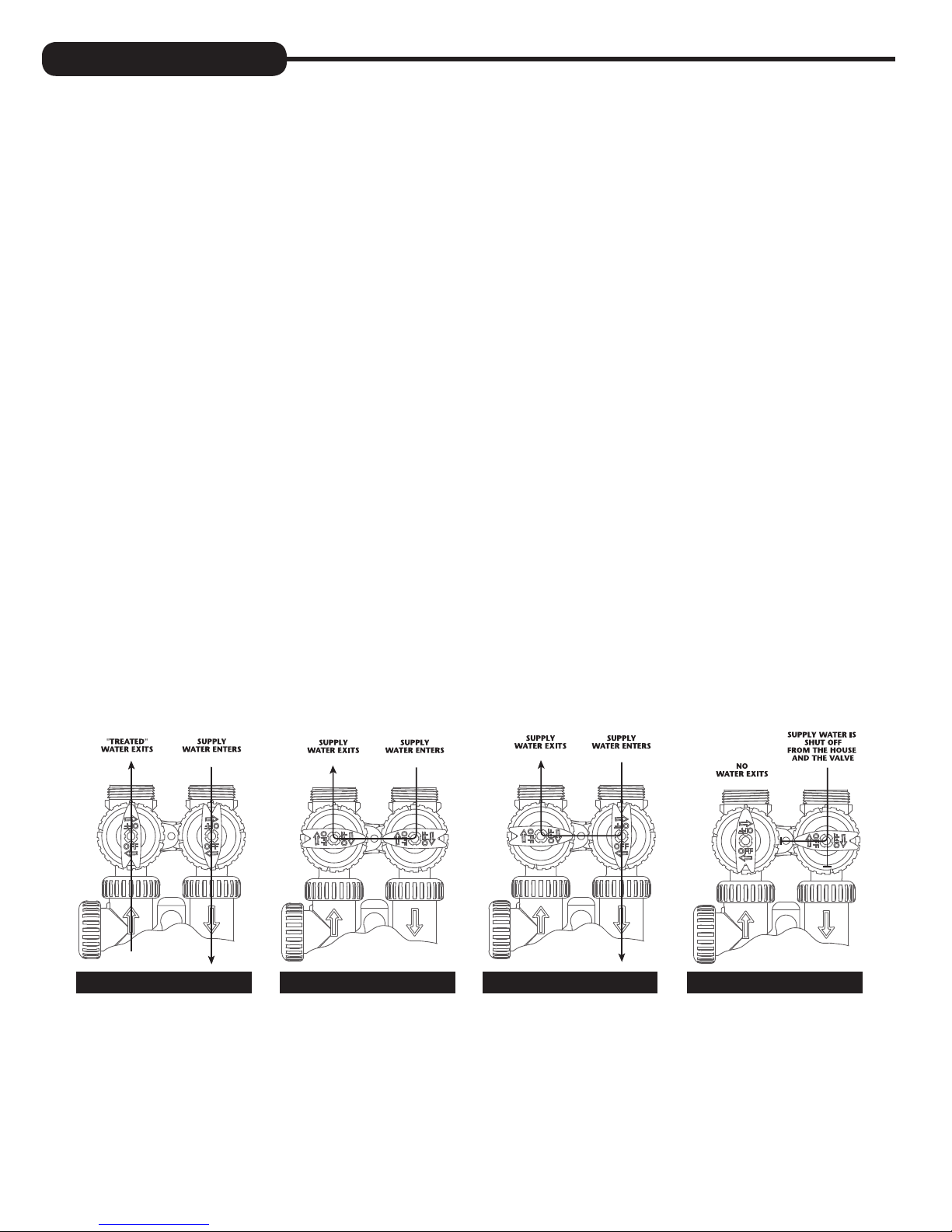
1. NORMAL OPERATION POSITION: The inlet and outlet handles point in the direction of flow indicated by the engraved
arrows on the control valve. Water flows through the control valve for normal operation of a water softener. During
the regeneration cycle this position provides regeneration water to the unit, while also providing untreated water to the
distribution system (Fig. 1).
2. BYPASS POSITION: The inlet and outlet handles point to the center of the bypass. The system is isolated from the water
pressure in the plumbing system. Untreated water is supplied to the building (Fig. 2).
3. DIAGNOSTIC POSITION: The inlet handle points toward the control valve and the outlet handle points to the center of
bypass valve. Untreated supply water is allowed to flow to the system and to the building, while not allowing water to exit
from the system to the building (Fig. 3). This allows the service technician to draw brine and perform other tests without the
test water going to the building.
NOTE: The system must be rinsed before returning the bypass valve to the normal position.
®
and the nuts and caps are glass-filled polypropylene. All seals are self-lubricating
4. SHUT OFF POSITION: The inlet handle points to the center of the bypass valve and the outlet handle points away from
the control valve. The water is shut off to the building. The water treatment system will depressurize upon opening a tap in
the building. A negative pressure in the building combined with the softener being in regeneration could cause a siphoning
of brine into the building. If water is available on the outlet side of the softener, it is an indication of water bypassing the
system (Fig. 4) (i.e. a plumbing cross-connection somewhere in the building).
NORMAL
OPERATION
POSITION
BYPASS POSITION
DIAGNOSTIC
POSITION
SHUT OFF
POSITION
FIGURE 1 FIGURE 3FIGURE 2 FIGURE 4
4
INSTALLATION:
GENERAL INSTALLATION & SERVICE WARNINGS
The control valve, fittings and/or bypass are designed to accommodate minor plumbing misalignments. There is a small
amount of “give” to properly connect the piping, but the water softener is not designed to support the weight of the plumbing.
Do not use Vaseline, oils, other hydrocarbon lubricants or spray silicone anywhere. A silicone lubricant may be used on black
“O” Rings, but is not necessary. Avoid any type of lubricants, including silicone, on red or clear lip seals.
Do not use pipe dope or other sealants on threads. Teflon
brine line connection at the control valve, and on the threads for the drain line connection. Teflon® tape is not used on the nut
connections or caps because “O” Ring seals are used. The nuts and caps are designed to be unscrewed or tightened by hand
or with the special plastic Service Wrench, #CV3193-02. If necessary pliers can be used to unscrew the nut or cap. Do not
use a pipe wrench to tighten nuts or caps. Do not place screwdriver in slots on caps and/or tap with a hammer.
SITE REQUIREMENTS
• water pressure – 25-100 psi • current draw is 0.5 amperes
• water temperature – 33-100°F (0.5-37.7°C) • the plug-in transformer is for dry locations only
• electrical – 115/120V, 60Hz uninterrupted outlet • the tank should be on a firm level surface
®
tape must be used on the threads of the 1” NPT inlet and outlet, the
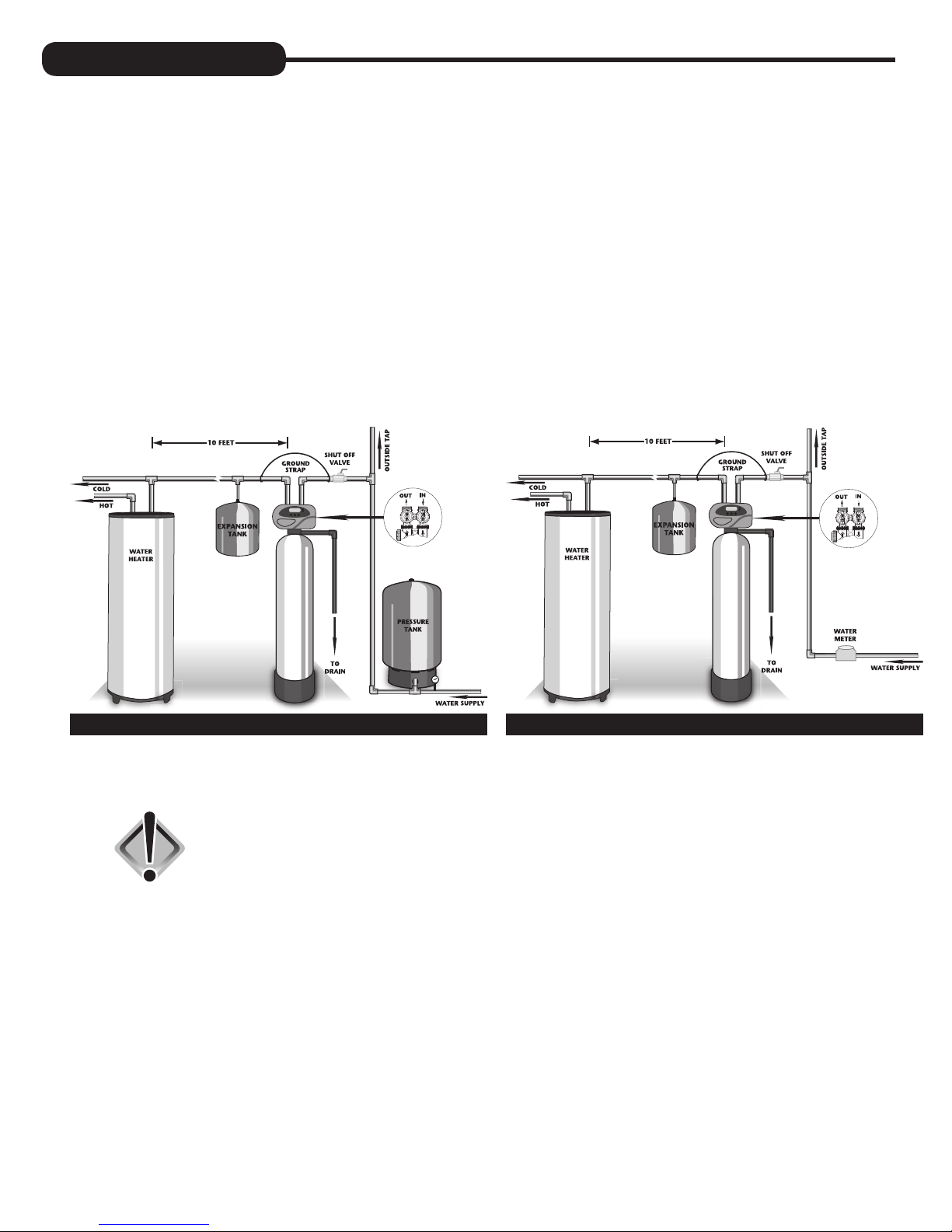
WELL WATER INSTALLATION MUNICIPAL INSTALLATION
1. The distance between the drain and the water conditioner should be as short as possible.
2. Do not install any water conditioner with less than 10 feet of piping between its outlet and the inlet of a water heater.
CAUTION: To protect the unit in the event of a hot water heater backup, the
manufacturer recommends the use of an expansion tank on the
outlet side of the unit.
3. Do not locate unit where it or its connections (including the drain and overflow lines) will ever be subjected to room
temperatures under 33°F.
4. Do not subject the tank to any vacuum, as this may cause an “implosion” and could result in leaking. If there is a possibility
a vacuum could occur, please make provision for a vacuum breaker in the installation.
5. INLET/OUTLET PLUMBING: Be sure to install Bypass Valve onto main control valve before beginning plumbing.
Make provisions to bypass outside hydrant and cold hard water lines at this time. Install an inlet shutoff valve and plumb
to the unit’s bypass valve inlet located at the right rear as you face the unit. There are a variety of installation fittings
available. They are listed under Installation Fitting Assemblies, page 26-27. When assembling the installation fitting
package (inlet and outlet), connect the fitting to the plumbing system first and then attach the nut, split ring and “O” Ring.
Heat from soldering or solvent cements may damage the nut, split ring or “O” Ring. Solder joints should be cool and
solvent cements should be set before installing the nut, split ring and “O” Ring. Avoid getting solder flux, primer, and
solvent cement on any part of the “O” Rings, split rings, bypass valve or control valve. If the building’s electrical system
is grounded to the plumbing, install a copper grounding strap from the inlet to the outlet pipe. Plumbing must be done in
accordance with all applicable local codes.
5
When installing an air regenerating filter the customer may experience, under
certain conditions, small amounts of air (cloudy water) at the taps. This is
normal. On rare occasions, this may result in “shots of air” at a particular
(Air charge
models only)
fixture. By installing a loop or “U” on the outlet side of the unit, this will act as
an air trap and improve this situation.
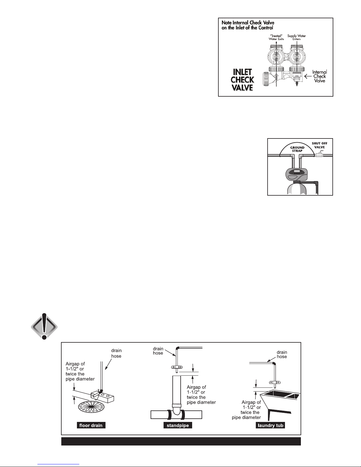
Located inside the inlet is an internal check valve (see diagram at right).
This check valve holds the air in the system, preventing its escape from the
tank. Plumbing codes may require the installation of a thermal expansion tank
on the outlet side of the system to prevent a water heater backup condition.
(See Installation Diagrams on page 5.)
Provisions should be made to bypass outside hydrants that are not to have filtered water. It is also advisable to install
hose bibs on the inlet and outside of the filter for future testing and service of the equipment. Where heavy sediment from
the well is observed, it is advisable to install a cartridge or bag-style filter immediately upstream from the filter. A nominal
micron rating of 50 to 100 is recommended. The purpose of this is to protect the control valve of any debris from the well.
If desired, a cartridge filter may be used after the system as a polishing filter.
6. INSTALLING GROUND: To maintain an electrical ground in metal plumbing of a home’s cold
water piping (such as a copper plumbing system), install a ground clamp or jumper wiring. If
replacing an existing filter, also replace the ground clamps/wire. If removing a filter, replace the
piping with the same type of piping as the original to assure plumbing integrity and grounding.
7. DRAIN LINE: First, be sure that the drain can handle the backwash rate of the system. Solder
joints near the valve must be done prior to connecting the drain line flow control fitting. Leave
at least 6” between the drain line flow control fitting and solder joints. Failure to do this could
cause interior damage to the flow control.
Backwash of an automatic filter can be directed into a septic tank in most cases, but because of the higher volume of
water discharged, care should be taken. The backwash discharge can be directed to a subsurface drainage system or
other safe location. Remember to follow all local codes.
When installing the drain line on any backwashing filter, especially Evolve filters that utilize air as the regenerant, hard
piping such as PVC, Schedule 80 Plastic or copper is recommended. Remove the drain line nut (if included) and discard.
A 3/4” NPT connection on the elbow is provided. During backwash, high volumes of water (more than a softener) and
air can be expelled. This release of air can cause a thrashing or movement of the drain line causing it to dislodge from the
drain, resulting in water damage. In order to prevent this, it is recommended to use other means of securing the drain line
to the floor, wall or ceiling to avoid this thrashing of piping. Our patent pending Backwash Air cycle greatly reduces the
chance of this occurring but should not be the only means of protection.
Where the drain line is elevated but empties into a drain below the level of the control valve, form a 7” loop at the
discharge end of the line so that the bottom of the loop is level with the drain connection on the control valve. This will
provide an adequate anti-siphon trap. Piping the drain line overhead <10 ft is normally not a problem. Be sure adequate
pressure is available (40-60 psi is recommended). Where the drain empties into an overhead sewer line, a sink-type trap
must be used. Run drain to its discharge point in accordance with plumbing codes. Pay special attention to codes for air
gaps and anti-siphon devices.
CAUTION: Never insert a drain line into a drain, sewer line, or trap. Always allow
an air gap between the drain line and the wastewater to prevent the
possibility of sewage being back-siphoned into the conditioner.
TYPICAL DRAIN LINE INSTALLATIONS
6
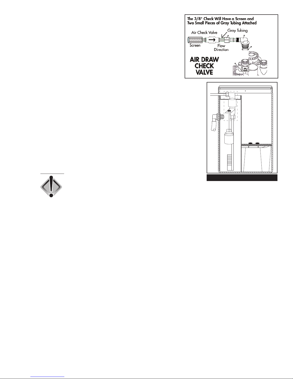
8. CHECK VALVE: On Evolve air filters, a 3/8” check valve is part of the
air draw assembly which includes tubing and a screen. Insert the tubing
into the elbow on the control valve (see diagram at right). As the
piston travels through various positions, ports are opened momentarily
(2-3 seconds) which may allow a small amount of water to discharge
through this assembly. The check valve prevents this flow of water.
NOTE: Under certain conditions (finished basement, utility room, etc.),
it may be advisable to run this air draw assembly to a drain.
9. DISINFECTION OF SYSTEM: In situations where additional disinfection is
needed, due to high levels of iron or sulfur bacteria, this may be accomplished
with a small chlorine feeder (see diagram at right). It can be used in
conjunction with air systems and is used to control bacterial growth within the
filter vessel itself. It is not used to control bacteria downstream of the filter nor for
disinfection of the water itself. Chlorine disinfection is not used with some medias
such as Birm. Please consult distributor or factory for more details.
This tank operates much the same way a brine tank does with a water softener.
A small amount of water is added to the tank just prior to regeneration, which
comes into contact with the chlorine pellets, dissolves them and is then drawn
into the filter to disinfect the system periodically and then safely rinsed away. We
recommend the use of pellets manufactured by Better Water Industries, available
through the manufacturer or your local distributor.
To Dealer:
CAUTION: On certain Evolve air models, the Backwash Air
cycle is not available when using the chlorine
feeder tank. Drain line must be of rigid materials and
affixed securely to floor, wall or ceiling. See Drain Line instructions.
CHLORINE FEEDER TANK
This tank has many intended uses. If chlorine is being used, add only two or
three pellets (two or three grams) of chlorine at a time. We recommend Better
Water Industries chlorine pellets. Do not overfill container. Use rubber gloves
when handling pellets. Always read safety precautions of chemical container
before adding to tank.
If chlorine is being used, never add or mix any chemical in chlorine tank other
than chlorine. Always read safety precautions on container before adding any
chemical to this tank. Only use in well ventilated area. Chlorine fumes can
be corrosive and harmful. Inhalation of chlorine gas can be deadly. Use drip
pan underneath tank in case of corrosion or leaking of tank. Always install
an overflow line to the chlorine tank and run to an appropriate drain. Do not
connect drain from filter to this tank. Drains should remain separate.
7
PROGRAMMING PROCEDURES:
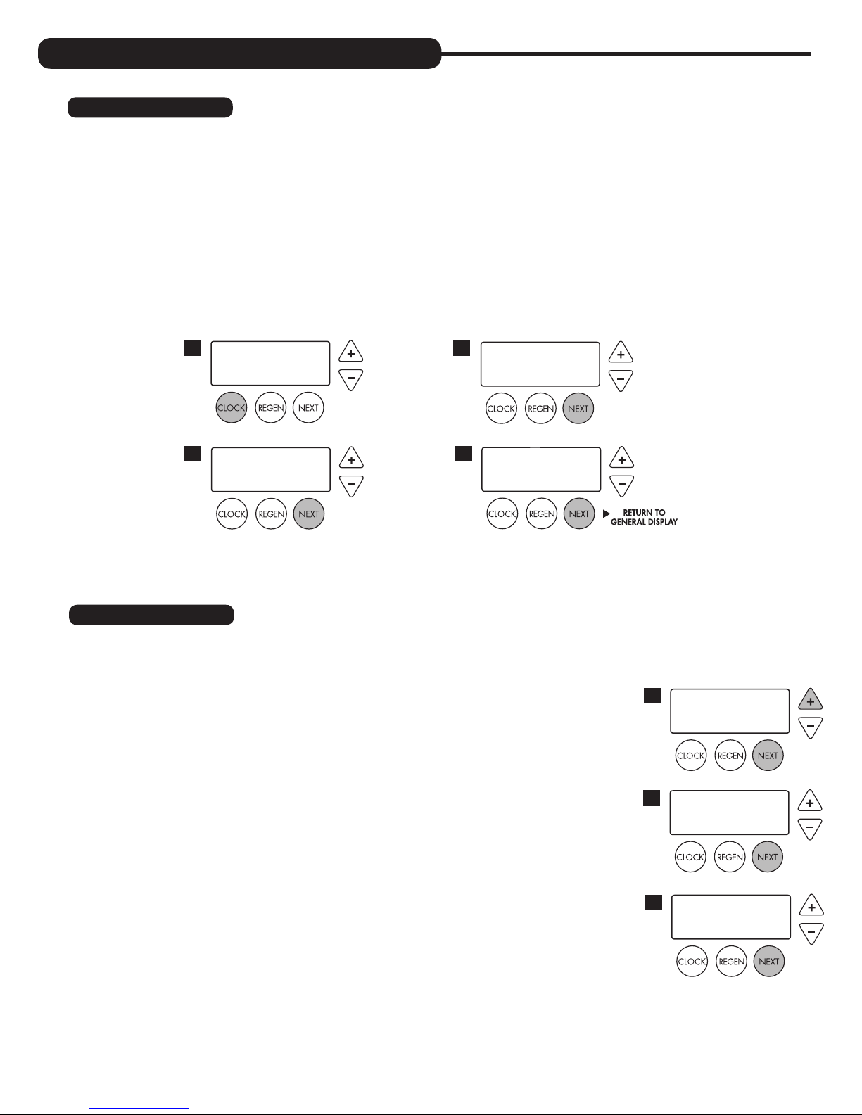
1. Set time of day:
Time of day should only need to be set after extended power outages or when daylight saving time begins or ends. If an
extended power outage occurs, the time of day will flash on and off indicating that the time should be reset.
STEP 1 – Press
STEP 2 – CURRENT TIME (HOUR): Set the hour of the day using + or — buttons. AM/PM toggles after 12.
STEP 3 – CURRENT TIME (MINUTES): Set the minutes using + or — buttons. If it is desired to back up to the
STEP 4 – CURRENT DAY: Set the day of the week using + or — buttons. Pressing
SET CLOCK.
Press
NEXT to go to step 3.
previous step press
return to the general operating display (page 9).
1
TIME MINUTES
3
SET
REGEN button once. Press NEXT to go to step 4.
2
4
2:10
AM
TIME HOUR
SET
CURRENT DAY
SET
2:00
MON
NEXT will exit SET CLOCK and
AM
2. Programming:
NOTE: The manufacturer has preset the unit so that the gallons between regenerations will be automatically calculated
after the hardness is entered.
STEP 1 – Press
STEP 2 – HARDNESS: Will not show because the manufacturer programmed the
NOTE: This display will show “–nA– (not available)” if “FILTER” is selected.
Press
Press
STEP 3 – DAYS BETWEEN REGENERATION (DAY OVERRIDE): The manufacturer
Set Day Override using + or — buttons (6 is recommended):
• set number of days between regeneration (1 to 28); or
• set to “OFF”
NEXT and + simultaneously for 3 seconds.
system to regenerate every 1,000 gallons or every 3 days as the default.
NEXT to go to step 3.
REGEN if you want to exit.
has factory set 6 DAYS as the default. This is the maximum number of days
between regenerations. If this is set to “OFF”, regeneration initiation is based
solely on gallons used. If any number is set (allowable range from 1 to 28), a
regeneration initiation will be called for on that day even if a sufficient number
of gallons were not used to call for a regeneration.
1
WATER HARDNESS
2
SET
DAYS BETWEEN REGEN
3
SET
-nA-
6
GR
8

NOTE: This valve has the capability of regenerating up to six times in one day.
This can be observed by pressing the
CLOCK and + buttons simultaneously, then
using + or — buttons to toggle the correct number of regenerations per day
as desired (see example to right). Press
NEXT to set the times per day or select
“OFF” to return to Days Between Regen. These settings are typically used in
commercial settings.
Press
NEXT to go to step 4. Press REGEN to return to the previous step.
REGENS PER DAY
SET
Example: Indicates unit set
to regen 4 times in one day.
4 PER
STEP 4 – REGENERATION HOUR: The manufacturer has factory set 2:00 A.M. as
the default. This is the hour of day for regeneration and can be reset by using
+ or — buttons. “AM/PM” toggles after 12. The default time is 2:00 a.m.
(recommended for a normal household).
Press
NEXT to go to step 5. Press REGEN to return to the previous step.
STEP 5 – REGENERATION MINUTES: Set the minutes using + or — buttons. Press
NEXT to go to step 6. Press REGEN to return to previous step. To initiate an
immediate manual regeneration, press and hold the
REGEN button for three
seconds. The system will begin to regenerate immediately. The control may
be manually stepped through the regeneration cycles by pressing REGEN.
Press
NEXT to go to step 6. Press REGEN to return to the previous step.
STEP 6 – SERVICE ALARM GALLONS: The manufacturer has factory set “OFF”
as the default. This feature is used to signal service into the future. This
is typically set by the installing dealer to warn homeowner that service is
required after a preset number of gallons have been consumed. If the
feature is active, a specific gallon amount will appear.
Press
NEXT three times to advance past this screen.
STEP 7 – SERVICE ALARM TIME: The manufacturer has factory set “OFF” as the
default. This feature is used to signal service into the future. This is typically
set by the installing dealer to warn homeowner that service is required after a
period of time has passed. If the feature is active, a specific number of days
will appear.
Press
NEXT three times to advance past this screen.
REGEN TIME HOUR
4
SET
REGEN TIME MINUTES
5
SET
SERVICE ALARM
6
SET
SERVICE ALARM
7
SET
2:00
2:00
OFF
OFF
AM
AM
GAL
YR
STEP 8 – ALARM BUZZER: The manufacturer has factory set “ON” as the default. An
alarm will sound (at the indicated time) after a regeneration, if there is no salt
or if another error has occurred. Turn the alarm “OFF” or “ON” using the + or
— buttons. Press
NEXT.
NOTE: This feature allows you to program the time in which the alarm
buzzer will sound, permitting the installer to pick a time when the owner will
be home or awake to hear it.
Setting Alarm Buzzer Start Time: Press + or — button to select the correct
hour the buzzer is to start sounding. Be sure to also set AM or PM as necessary.
(Default is set to 6:00 a.m.) Press
NEXT.
Setting Alarm Buzzer End Time: Press + or — button to select the
correct hour the buzzer is to stop sounding in the day. Be sure to also set
AM or PM as necessary. (Default is set to 10:00 p.m.) Press
NEXT.
STEP 9 – DISPLAY BACKLIGHT: The manufacturer has factory set “ON” as the
default. Turn the light “OFF” or “ON” using the + or — buttons. “OFF”
will turn display backlight off after five minutes of keypad inactivity.
Press
NEXT to exit installer programming.
ALARM BUZZER START
8
SET
ALARM BUZZER END
SET
LIGHT NORMALLY
9
SET
10:00
6:00
ON
AM
PM
9

START-UP INSTRUCTIONS:
FLUSHING OF SYSTEM:
To flush the system of any debris and air after installation is complete, please perform the following steps:
1. Rotate bypass handles to the bypass mode (see Fig. 2 of page 4).
2. Turn on inlet water and check for leaks in the newly installed plumbing.
3. Fully open a cold water faucet, preferable at a laundry sink or bathtub without an aerator.
4. Wait two to three minutes or until water runs clear, then turn water off and follow start-up instructions.
System regeneration sequence is in the following order. Some sequence differences may be noticed depending upon local
conditions. (If it is desired to change this sequence, please refer to the Dealer Manual or contact the manufacturer.)
Sequencing for Various Filters:
Air Filters Backwashing Filters Acid Neutralizers
1. Backwash Air 1. Backwash 4. Rinse 1. Backwash 5. Filtering
2. Backwash 2. Rinse 5. Return to service 2. Filtering 6. Rapid Rinse
3. Regenerant Draw Down (Air draw) 3. Backwash 3. Rapid Rinse 7. Return to service
4. Return to service 4. Backwash
Inch Worm Feature: Evolve air units are programmed with the backwash air cycle feature (nicknamed “inch
worm”). This unique feature allows for small movements or “inching” of the piston towards the backwash cycle. As the
piston approaches this cycle, the backwash port opens slightly with each advancement, allowing air to escape to drain.
This cycle is ten very small mini steps of the piston which take place thirty seconds apart. Usually midway between the
ten positions, the air begins to be released very slowly to the drain in normal operating conditions.
When first starting up an air sulfur or air iron, it is advised to step through these positions and go to the normal backwash
cycle in order to fill the unit.
To advance in Backwash Air cycle:
1. Pushing the
NEXT button will advance to each of the ten mini steps within the backwash air cycle. While there are
usually eight steps to this cycle, the valve may make two or three movements for each step. Wait for these movements
to complete before pressing
2. Pushing and holding the
NEXT again.
REGEN button for three seconds while in the Backwash Air cycle will skip the remaining mini
steps and proceed to the next cycle of regeneration which is usually Backwash.
The system is now ready for filling with water and for testing.
1. Place the bypass valve into the bypass mode (Fig. 2 on page 4).
2. Press and hold the
REGEN button until the motor starts. Release button. Put the valve into “BACKWASH” position. (Please
see note above.) Unplug the transformer so that the valve will not cycle to the next position. Open the inlet handle of the
bypass valve very slightly allowing water to fill the tank slowly in order to expel air.
CAUTION: If water flows too rapidly, there will be a loss of media to the drain. Certain
medias such as carbon, or other dry media, should not be backwashed
immediately for extended periods of time. These medias need to “soak”
in the water for a 24-hour period prior to full backwash conditions.
Media is dry and filling with water too quickly in backwash will result in
media plugging the drain and valve assembly.
3. When the water is flowing steadily to the drain without the presence of air, slowly open the inlet valve. Restore power
and momentarily press the
REGEN button to advance the control to the “REGENERANT DRAW DOWN” position.
4. With the bypass still in the diagnostic mode (Fig. 3 on page 4), there should be a slow flow to the drain.
5. Press
REGEN button in sequence until display returns to “TIME.” Place bypass valve in the normal operating mode
(Fig. 1 on page 4) by opening the outlet bypass handle.
6. Go to laundry tub or bathtub faucet, preferable a faucet without an aerator, and turn on cold water. Let the water run.
Note the color of water coming from faucet. If discolored, let water run until clear. If severely discolored, place unit into
“BACKWASH” position (step 2) and run water to the system’s drain until clear.
Note: At no time should there by large particles of media noticed at faucet or laundry tub. If this is seen, immediately shut off
water and bypass system, as this could be an indication of a distributor failure. Contact manufacturer or distributor for assistance.
7. Place unit into regeneration again and allow to complete cycle. Upon completion, unit will be regenerated and will deliver
treated water.
10
 Loading...