


FURY6
Original Instructions
EN
DE
FR
TR
Written in UK English |
Date Published: 01 / 03 / 2016 |


ENGLISH
EN
Original Instructions
DE
FR
TR

|
|
www.evolutionpowertools.com |
|
|
|
|
|
TABLE OF CONTENTS |
|
|
|
|
|
|
|
English |
|
Page 2 |
|
Deutsch |
|
Seite 34 |
|
Français |
|
Page 68 |
|
Türk |
|
Sayfa 100 |
|
|
|
|
|
INTRODUCTION |
|
Page 5 |
|
Guarantee |
|
Page 5 |
|
Machine Specification |
|
Page 6 |
|
Vibration |
|
Page 7 |
|
Labels and Symbols |
|
Page 7 |
|
Intended use of this Power Tool |
|
Page 8 |
|
Prohibited use of this Power Tool |
|
Page 8 |
|
|
|
|
|
SAFETY PRECAUTIONS |
|
Page 9 |
|
Electrical Safety |
|
Page 9 |
|
Outdoor Use |
|
Page 9 |
|
General Power Tool Safety Instructions |
|
Page 11 |
|
Additional Safety Instructions |
|
Page 13 |
|
|
|
|
|
GETTING STARTED |
|
Page 14 |
|
Unpacking |
|
Page 14 |
|
Machine Overview |
|
Page 15 |
|
Service Parts Diagram |
|
Page 16 |
|
Assembly and Preparation |
|
Page 17 |
|
Operating Instructions |
|
Page 18 |
|
|
|
|
|
MAINTENANCE |
|
Page 29 |
|
Environmental Protection |
|
Page 29 |
|
|
|
|
|
DECLARATION OF CONFORMITY |
|
Page 31 |
|
4

www.evolutionpowertools.com
(1.2) THIS INSTRUCTION MANUAL WAS ORIGINALLY WRITTEN IN ENGLISH
(1.3) IMPORTANT
Please read these operating and safety instructions carefully and completely. For your own safety, if you are uncertain about any aspect of using this equipment
please access the relevant Technical Helpline, the number of which can be found on the Evolution Power Tools website. We operate several Helplines throughout our worldwide organization, but Technical help is also available from your supplier.
WEB
www.evolutionpowertools.com
(1.4) Congratulations on your purchase of an Evolution Power Tools Machine. Please complete your product registration ‘online’ as explained in the A4 online
guarantee registration leaflet included with this machine. You can also scan the QR code found on the A4 leaflet with a Smart Phone.
This will enable you to validate your machine’s guarantee period via Evolutions website by entering your details and thus ensure prompt service if ever needed. We sincerely thank you for selecting a product from
Evolution Power Tools.
EVOLUTION LIMITED GUARANTEE.
Evolution Power Tools reserves the right to make improvements and modifications to the product design without prior notice.
Please refer to the guarantee registration leaflet and/or the packaging for details of the terms and conditions of the guarantee.
(1.5) Evolution Power Tools will, within
the guarantee period, and from the original date of purchase, repair or replace any goods found to be defective in materials or
workmanship. This guarantee is void if the tool being returned has been used beyond the recommendations in the Instruction Manual or if the machine has been damaged by accident, neglect, or improper service.
This guarantee does not apply to machines and / or components which have been altered, changed, or modified in any way, or subjected to use beyond recommended capacities
and specifications. Electrical components are subject to respective manufacturers’ warranties. All goods returned defective shall be returned prepaid freight to Evolution Power Tools.
Evolution Power Tools reserves the right to optionally repair or replace it with the same or equivalent item. There is no warranty – written or verbal – for consumable accessories such as (following list not exhaustive) blades, cutters, drills, chisels or paddles etc. In no event shall Evolution Power Tools be liable for loss or damage resulting directly or indirectly from the use of our merchandise or from any other cause. Evolution Power Tools is not liable for any costs incurred on such goods or consequential damages. No officer, employee
or agent of Evolution Power Tools is authorized to make oral representations of fitness or
to waive any of the foregoing terms of sale and none shall be binding on Evolution Power Tools.
Questions relating to this limited guarantee should be directed to the company’s head office, or call the appropriate Helpline number.
5
EN
DE
FR
TR

www.evolutionpowertools.com
SPECIFICATIONS
MACHINE |
METRIC |
IMPERIAL |
|
|
|
Motor (230-240V~ 50 Hz) |
1200W |
5A |
|
|
|
Speed No Load |
3500min-1 |
3500rpm |
Weight |
9.45kg |
20lb |
|
|
|
CUTTING CAPACITIES |
|
METRIC |
IMPERIAL |
|
|
|
|
|
|
Mild Steel Plate - Max Thickness |
|
3mm |
1/8” |
|
|
|
|
|
|
|
|
|
||
MAXIMUM CUTTING CAPACITY (ALUMINIUM, WOOD & PVC) |
||||
|
MITRE SAW CONFIGURATION |
|
||
|
|
|
|
|
MITRE |
|
BEVEL |
MAX WIDTH |
MAX DEPTH |
|
OF CUT |
OF CUT |
||
|
|
|
||
|
|
|
|
|
90° |
|
90° |
115mm (4-1/2”) |
55mm (2-1/8”) |
|
|
|
|
|
45° |
|
90° |
65mm (2-1/2”) |
55mm (2-1/8”) |
|
|
|
|
|
45° |
|
45° |
40mm (1-9/16”) |
25mm (15/16”) |
|
|
|
|
|
|
|
|||
MAXIMUM CUTTING CAPACITY - TABLE SAW CONFIGURATION |
||||
|
|
|
|
|
CUTTING CAPACITIES |
|
METRIC |
IMPERIAL |
|
|
|
|
|
|
Wood - Max Thickness |
|
32mm |
1-1/4” |
|
|
|
|
|
|
|
|
|
|
|
BLADE DIMENSIONS |
|
METRIC |
IMPERIAL |
|
|
|
|
|
|
Diameter |
|
210mm |
8-1/4” |
|
|
|
|
|
|
Bore |
|
25.4mm |
1” |
|
|
|
|
|
|
Number of Teeth |
|
20 |
20 |
|
|
|
|
|
|
Kerf |
|
1.7mm |
1/16” |
|
|
|
|
|
|
NOISE & VIBRATION DATA
Sound Pressure LPA |
94.57dB(A) K=3dB(A) |
|
|
Sound Power Level LWA |
107.57dB(A) K=3dB(A) |
Vibration Level |
2.5m/s2 K=1.5m/s2 |
(1.6) Note: The vibration measurement was made under standard conditions in accordance with: BS EN 61029-1:2009+A11.
6

www.evolutionpowertools.com
The declared vibration total value has been measured in accordance with a standard test method and may be used for comparing one tool with another.
The declared vibration total value may also be used in a preliminary assessment of exposure.
(1.7) VIBRATION
WARNING: When using this machine the operator can be exposed to high levels of vibration transmitted to the hand and arm. It is possible that the operator could develop “Vibration white finger disease” (Raynaud syndrome). This condition can reduce the sensitivity of the hand to temperature as well as producing general numbness. Prolonged or regular users of this machine should monitor the condition of their hands and fingers closely. If any of the symptoms become evident, seek immediate medical advice.
•The measurement and assessment of human exposure to hand-transmitted vibration in the workplace is given in: BS EN ISO 5349-1:2001 and
BS EN ISO 5349-2:2002.
•Many factors can influence the actual vibration level during operation e.g. the work surfaces condition and orientation and the type and condition of the machine being used. Before each use, such factors should be assessed, and where possible appropriate working practices adopted. Managing these factors can help reduce the effects of vibration:
Handling
•Handle the machine with care, allowing the machine to do the work.
•Avoid using excessive physical effort on any of the machines controls.
•Consider your security and stability, and the orientation of the machine during use.
Work Surface
•Consider the work surface material; its condition, density, strength, rigidity and orientation.
WARNING: The vibration emission during actual use of the power tool can differ from the declared total value depending on the ways in which the tool is used. The need to identify safety measures and to protect the operator are based on an estimation of exposure in the actual conditions of use
(taking account of all parts of the operating cycle, such as the times the tool is switched off, when it is running idle, in addition
to trigger time).
(1.8) LABELS & SYMBOLS
WARNING: Do not operate this machine if warning and/or instruction labels are missing or damaged. Contact Evolution Power Tools for replacement labels.
Note: All or some of the following symbols may appear in the manual or on the product.
7
EN
DE
FR
TR
www.evolutionpowertools.com
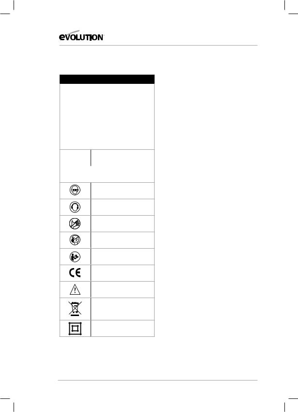
(1.9) LABELS & SYMBOLS
Symbol |
Description |
|
|
V |
Volts |
|
|
A |
Amperes |
|
|
Hz |
Hertz |
|
|
Min-1 |
Speed |
|
|
~Alternating Current
no |
No Load Speed |
|
|
Wear Safety Goggles
Wear Ear Protection
Do Not Touch
Wear Dust Protection
Read Instructions
CE certification
Warning
Waste electrical and electronic equipment
Double Insulated
(1.10) INTENDED USE OF THIS POWER TOOL
WARNING: This product is a Hand Operated Compound Mitre Saw and has been designed to be used with special Evolution blades. Only use accessories designed for use in
this machine and/or those recommended specifically by Evolution Power Tools Ltd.
When fitted with an appropriate blade this machine can be used to cut:
Mild Steel
Aluminium
Wood
(1.11) PROHIBITED USE OF THIS POWER TOOL
WARNING: This product is a Hand Operated Compound Mitre Saw and must only be used as such. It must not be modified in any way, or used to power any other equipment or drive any other accessories other than those mentioned in this Instruction Manual.
(1.13) WARNING: This machine is not intended for use by persons (including children) with reduced physical, sensory or mental capabilities, or lack of experience and knowledge, unless they have been
given supervision or instruction concerning the safe use of the machine by a person responsible for their safety and who
is competent in its safe use.
Children should be supervised to ensure that they do not have access to, and are not allowed to play with, this machine.
8

www.evolutionpowertools.com
(1.14) ELECTRICAL SAFETY
This machine is fitted with the correct moulded plug and mains lead for the designated market. If the supply cord is damaged, it must be replaced by a special cord or assembly available from the manufacturers or its service agent.
(1.15) OUTDOOR USE
WARNING: For your protection if this
tool is to be used outdoors it should not be exposed to rain, or used in damp locations. Do not place the tool on damp surfaces.
Use a clean, dry workbench if available. For added protection use a residual current device (R.C.D.) that will interrupt the supply
if the leakage current to earth exceeds 30mA for 30ms. Always check the operation of the residual current device (R.C.D.) before using the machine.
If an extension cable is required it must be a suitable type for use outdoors and
so labelled. The manufacturers instructions should be followed when using an extension cable.
(2.1) POWER TOOL GENERAL SAFETY
INSTRUCTIONS
(These General Power Tool Safety Instructions are as specified in BS EN 60745-1:2009 &
EN 61029-1:2009)
WARNING: Read all safety warnings and instructions. Failure to follow the warnings and instructions may result in electric shock, fire and/ or serious injury.
(2.2) 1) General Power Tool
Safety Warnings [Work area safety]
a)Keep work area clean and well lit.
Cluttered or dark areas invite accidents.
b)Do not operate power tools in explosive atmospheres, such as in the presence of flammable liquids, gasses or dust. Power
tools create sparks which may ignite the dust or fumes.
c) Keep children and bystanders away while operating power tool. Distractions can cause you to lose control.
(2.3) 2) General Power Tool Safety
Warnings [Electrical Safety]
a)Power tool plugs must match the outlet.
Never modify the plug in any way. Do not use any adapter plugs with earthed (grounded) power tools. Unmodified plugs and matching outlets will reduce the risk of electric shock.
b)Avoid body contact with earthed
or grounded surfaces, such as pipes, radiators, ranges and refrigerators.
There is an increased risk of electric shock if your body is earthed or grounded.
c) Do not expose power tools to rain or wet conditions. Water entering a power tool will increase the risk of electric shock.
d) Do not abuse the cord. Never use the cord for carrying, pulling or unplugging the power tool. Keep cord away from heat, oil, sharp edges or moving parts. Damaged or entangled cords increase the risk of electric shock.
e) When operating a power tool outdoors, use an extension cord suitable for outdoor use. Use of a cord suitable for outdoor use reduces the risk of electric shock. f) If operating a power tool in a damp location is unavoidable, use a residual current device (RCD) protected supply.
Save all warnings and instructions for future |
Use of an RCD reduces the risk |
reference. The term “power tool” in the |
of electric shock. |
warnings refers to your mains-operated |
|
(corded) power tool or battery-operated |
|
(cordless) power tool. |
|
9
EN
DE
FR
TR

www.evolutionpowertools.com
(2.4) 3) General Power Tool Safety Warnings [Personal Safety].
a) Stay alert, watch what you are doing and use common sense when operating a power tool. Do not use a power tool while you are tired or under the influence of drugs, alcohol or medication. A moment of inattention while operating power tools may result in serious personal injury.
b)Use personal protective equipment.
Always wear eye protection. Protective equipment such as dust masks, non-skid safety shoes, hard hat or hearing protection used
for appropriate conditions will reduce personal injuries.
c)Prevent unintentional starting. Ensure the
switch is in the off-position before connecting to power source and or battery pack, picking up or carrying the tool. Carrying power tools with your finger on the switch or energising the power tools that have the switch on invites accidents.
d) Remove any adjusting key or wrench before turning the power tool on. A wrench or key left attached to a rotating part of a power tool may result in personal injury .
e) Do not overreach. Keep proper footing and balance at all times. This enables better control of the power tool in unexpected situations.
f)Dress properly. Do not wear loose clothing or jewellery. Keep your hair, clothing and gloves away from moving parts. Loose clothes, jewellery or long hair can be
caught in moving parts.
g)If devices are provided for the connection of dust extraction and collection facilities, ensure that these are connected and properly used. Use of dust collection can
reduce dust-related hazards.
(2.5) 4) General Power Tool Safety Warnings [Power tool use and care]. a) Do not force the power tool. Use the correct power tool for your application.
The correct power tool will do the job better and safer at a rate for which
it was designed.
b) Do not use the power tool if the switch does not turn it on or off. Any power tool that cannot be controlled with the switch is dangerous and must be repaired.
c) Disconnect the power tool from the power source and/or battery pack from the power tool before making any adjustments, changing accessories, or storing power tools. Such preventative safety measures reduce the risk of starting the power tool accidentally.
d) Store idle power tools out of the reach of children and do not allow persons unfamiliar with the power tool or these Instructions to operate the power tool.
Power tools are dangerous in the hands of untrained users.
e) Maintain power tools. Check for misalignment or binding of moving parts, breakage of moving parts and any other condition that may affect the power tools operation. If damaged, have the power tool repaired before use. Many accidents are caused by poorly maintained power tools.
f)Keep cutting tools sharp and clean.
Properly maintained cutting tools with sharp cutting edges are less likely to bind and are easier to control.
g)Use the power tool, accessories and tool bits etc. in accordance with these instructions, taking into account the working conditions and the work to be performed. Use of the power tool for
operations different from those intended could result in a hazardous situation.
10
www.evolutionpowertools.com
(2.6) 5) General Power Tool
Safety Warnings [Service]
a) Have your power tool serviced by a qualified repair person using only identical replacement parts. This will ensure that the safety of the power tool is maintained.
(2.7) HEALTH ADVICE
WARNING: When using this machine, dust particles may be produced. In some instances, depending on the materials you are working with, this dust can be particularly harmful.
If you suspect that paint on the surface of material you wish to cut contains lead, seek professional advice. Lead based paints should only be removed by a professional and you should not attempt to remove it yourself. Once the dust has been deposited on surfaces, hand to mouth contact can result in the ingestion of lead.
Exposure to even low levels of lead can cause irreversible brain and nervous system damage. The young and unborn children are particularly vulnerable. You are advised to
consider the risks associated with the materials you are working with and to reduce the risk
of exposure. As some materials can produce dust that may be hazardous to your health, we recommend the use of an approved face mask with replaceable filters when using this machine.
You should always:
•Work in a well-ventilated area.
•Work with approved safety equipment, such as dust masks that are specially designed to filter microscopic particles.
(2.8) WARNING: the operation of any power tool can result in foreign objects being thrown towards your eyes, which could result in severe eye damage. Before beginning power tool operation, always wear safety goggles
or safety glasses with side shield or a full face shield where necessary.
(3.5) ADDITIONAL SAFETY INSTRUCTIONS - MITRE SAWS
The following specific safety instructions
for Mitre Saws are based on the requirements of EN61029-2-9:2009.
BLADE SAFETY
WARNING: Rotating Circular Saw Blades are extremely dangerous and can cause serious injury and amputation. Always keep fingers and hands at least 150mm away from the blade at all times. Never attempt to retrieve sawn material until the cutting head is in the raised position, the guard is fully closed and the saw blade has stopped rotating.
Only use saw blades that are recommended by the manufacturer and as detailed in
this manual and that comply with the requirements of EN 847-1.
Do Not use saw blades that are damaged or deformed as they could shatter and cause serious injury to the operator or bystanders.
Do Not use saw blades that are manufactured from high speed steel (HSS).
If the table insert becomes damaged or worn it must be replaced with an identical one available from the manufacturer
as detailed in this manual.
11
EN
DE
FR
TR

www.evolutionpowertools.com
(3.6) PERSONAL PROTECTIVE EQUIPMENT (PPE)
Hearing protection should be worn in order to reduce the risk of induced hearing loss.
Eye protection should be worn in order to prevent the possibility of the loss of sight from ejected chippings.
Respiratory protection is also advised as some wood and wood type products especially MDF (Medium Density Fibreboard) can produce dust that can be hazardous to your health.
We recommend the use of an approved face mask with replaceable filters when using this machine in addition to using the dust extraction facility.
Gloves should be worn when handling blades or rough material. It is recommended that saw blades should be carried in a holder wherever practicable. It is not advisable to wear gloves when operating the mitre saw.
(3.7) SAFE OPERATION
Always ensure that you have selected the correct saw blade for the material being cut. Do Not use this mitre saw to cut materials other than those specified in this Instruction Manual.
When transporting a mitre saw ensure that the cutting head is locked in the 90 degree down position (if a sliding mitre saw ensure that the slide bars are locked). Lift the machine by gripping the outer edges of the base with both hands (if a sliding mitre saw, transport using the handles provided). Under no circumstances shall the machine be lifted
or transported using the retractable guard or any part of its operating mechanism.
Before each use check the operation
of the retractable guard and its operating mechanism ensuring that there is no damage, and that all moving parts operate
smoothly and correctly.
Keep the work bench and floor area clear of all debris including sawdust, chips and off-cuts.
Always check and ensure that the speed marked on the saw blade is at least equal to the no load speed marked on the mitre saw.
Under no circumstances shall a saw blade be used that is marked with a speed that is less than the no load speed marked
on the mitre saw.
Where it is necessary to use spacer or reducing rings these must be suitable for the intended purpose and only as recommended by the manufacturer.
If the mitre saw is fitted with a laser it shall not be replaced with a different type. If the laser fails to operate it shall be repaired or replaced by the manufacturer or his authorised agent. The saw blade shall only be replaced as detailed in this Instruction Manual.
Never attempt to retrieve off-cuts or any other part of the work piece until the cutting head is in the raised position, the guard is fully closed and the saw blade has stopped rotating.
12

www.evolutionpowertools.com
(3.8) PERFORM CUTS
CORRECTLY & SAFELY
Wherever practicable always secure the work piece to the saw table using the work clamp where provided.
Always ensure that before each cut the mitre saw is mounted in a stable position.
If needed the mitre saw can be mounted
on a wooden base or work bench or attached to a mitre saw stand as detailed in this Instruction Manual.
Long work pieces should be supported on the work supports provided or on appropriate additional work supports.
(3.4) WARNING: If any parts are missing, do not operate your machine until the missing parts are replaced. Failure to follow this rule could result in serious personal injury.
(3.9) ADDITIONAL SAFETY ADVICE CARRYING YOUR TABLE MITRE SAW
Safety Advice
•Although compact, this saw is heavy.
To reduce the risk of back injury, get competent help whenever you have to lift the saw.
•To reduce the risk of back injury, hold the tool close to your body when lifting.
Bending your knees so you can lift with your legs, not your back. Lift by using the handhold areas at each side of the machines base.
•Never carry the Table Mitre Saw by the power cord. Carrying the tool by the power cord could cause damage to the insulation or the wire connections resulting in electric shock or fire.
•Before moving the saw tighten the mitre and bevel locking screws to guard against sudden unexpected movement.
•Lock the Cutting Head in its lowest position.
Ensure that the Cutting Head Locking Pin is completely engaged in its socket.
WARNING: Do not use the blade guard as a ‘lifting point’. The power cord must be removed from the power supply before attempting to move the machine.
•Lock the Cutting Head in the down position using the Cutting Head locking pin.
•Loosen the Mitre Angle Locking Screw.Turn the table to either of its maximum settings.
•Lock the table in position using the Locking
Screw.
•Use the two carry handle cut-outs machined into either side of the machine base, to transport the machine.
Place the saw on a secure stationary work surface and check the saw over carefully.
Check particularly the operation of all the machines safety features before attempting to operate the machine.
(4.1) GETTING STARTED - UNPACKING
Caution: This packaging contains sharp objects. Take care when unpacking. Remove the machine, together with the accessories supplied from the packaging. Check carefully to ensure that the machine is in good condition and account for all the accessories listed in this manual.
Also make sure that all the accessories are complete. If any parts are found to be missing, the machine and its accessories should be returned together in their original packaging to the retailer. Do not throw the packaging away; keep it safe throughout the guarantee period. Dispose of the packaging in an environmentally responsible manner. Recycle if possible. Do not let children play with empty plastic bags due to the risk of suffocation.
13
EN
DE
FR
TR

www.evolutionpowertools.com
(4.2) ITEMS SUPPLIED
Description |
Quantity |
|
|
Instruction Manual |
1 |
|
|
Hold Down Clamp |
1 |
|
|
Push Stick |
1 |
|
|
Pin Spanner (Blade Change) |
1 |
|
|
Hex Key 6mm |
1 |
(Blade Change) |
|
|
|
Hex Key 5mm |
1 |
(Riving Knife Adjustment) |
|
|
|
Multi-Purpose Blade (Fitted) |
1 |
|
|
Rip Fence/ |
1 |
Bevel Guide Assembly |
|
|
|
Auxiliary Lower Blade Guard |
1 |
(Fitted) |
|
|
|
Dust Bag Adaptor Tube |
1 |
|
|
Workpiece Supports |
2 |
|
|
Rear Stabilising Arms |
2 |
|
|
(4.3) ADDITIONAL ACCESSORIES
In addition to the standard items supplied with this machine the following accessories are also available from the Evolution online shop at www.evolutionpowertools.com or from your local retailer.
(4.4)
Description |
Part No |
|
|
FURY Blade |
FURY210 |
|
|
14

www.evolutionpowertools.com
LH VIEW OF FURY 6 MITRE SAW CONFIGURATION |
EN |
|
|
11 |
|
1 |
|
12 |
|
3 |
|
4 |
5 |
|
9 |
2 |
8 |
|
|
6 |
10 |
|
|
7 |
DE
FR
1. |
CUTTING HANDLE |
7. |
MITRE ANGLE SCALE |
2. |
ROTARY TABLE |
8. |
FENCE |
3. |
RETRACTABLE LOWER BLADE GUARD |
9. |
HOLD DOWN CLAMP |
4. |
BLADE |
10. |
STABILISING ARMS |
5. |
BEVEL LOCKING LEVER |
|
(X2 Back of machine) |
|
(Back of the machine) |
11. |
CUTTING HEAD RELEASE LEVER |
6. |
MITRE ANGLE LOCKING SCREW |
12. |
TABLE HEIGHT ADJUSTING SCREW |
TR
15

www.evolutionpowertools.com
LH VIEW OF FURY 6 TABLE SAW CONFIGURATION
6 |
10 |
|
|
|
7 |
4 |
|
|
1 |
|
3 |
|
2 |
|
5 |
|
9 |
|
8 |
1. |
ON/OFF TRIGGER SWITCH (Inside handle) |
7. |
RIP FENCE |
2. |
ON/OFF LATCHING SWITCHES |
8. |
PUSH STICK |
3. |
CUTTING HANDLE |
9. |
MOUNTING HOLE (2 at the front and |
4. |
TABLE TOP |
|
2 under the stabilising arms) |
5. |
AUXILIARY LOWER BLADE GUARD |
10. |
CUTTING HEAD LATCHING PIN |
6. |
UPPER BLADE GUARD |
|
(Not shown in this view) |
16

www.evolutionpowertools.com
GETTING STARTED
WARNING: ALWAYS DISCONNECT THE SAW FROM THE POWER SOURCE BEFORE MAKING ANY ADJUSTMENTS.
Refer to the “Service Parts Diagram”. Install a blade as detailed in the “Installing or Removing the Blade” section.
Note: We recommend that the operator reads the ‘Important Information’ sticker applied to the table of the Fury6. Practicing and becoming familiar with the procedures outlined on
this sticker will make subsequent adjustments/assembly or configuring fairly straightforward.
PERMANENTLY MOUNTING THE FURY6 TABLE/MITRE SAW (Fig. 1)
WARNING: To reduce the risk of injury from unexpected saw movement, place the saw in the desired location either on a workbench or other recommended leg set. The base of the saw has four holes to mount the mitre saw. If the saw is to be used in one location, permanently fasten it to the workbench or leg set using appropriate bolts with lock washers and nuts.
Note:When permanently mounting the Fury6 we recommend that the four (4) rubber feet located underneath each of the mounting holes are removed and stored safely for possible future use.
1.Tighten the mitre and bevel locks.
2.Position the saw so other people cannot stand behind it. Thrown debris could injure people in its path.
3.Place the saw on a firm, level surface where there is plenty of room for handling and properly supporting the workpiece.
4.Support the saw so that the table is level and the saw does not rock.
5.Bolt or clamp the saw to its support.
For Portable Use (Fig. 2)
Note: The Fury6 is designed to be a highly portable machine.
For portable use the Fury6 must be fitted with the two (2) rear Stabilising Arms.
|
EN |
(1) |
|
(2) |
|
(3) |
|
(4) |
|
(5) |
|
(6) |
|
(7) |
(8) |
|
|
|
(9) |
Fig. 1
1) Hex headed bolt |
|
|
2) Spring washer |
|
|
3) Flat washer |
|
|
4) Mitre saw base |
DE |
|
5) Workbench |
||
|
6)Flat washer
7)Spring washer
8)Hex nut
9)Lock nut
FR
Fig. 2
TR
17
www.evolutionpowertools.com
Fig. 3a
Fig. 3b
(Dust bag, not supplied)
Fig. 4
To fit the Stabilising Arms:
•Remove the cross head machine screws from the two (2) rear mounting positions.
•Attach the Stabilising Arms with the machine screws, two per arm and tighten securely.
Note: The Stabilising Arms are fitted with rubber feet. The base of the Fury6 is also fitted with four (4) identical rubber feet positioned underneath the mounting holes in the base.
When used as a portable machine the six (6) rubber feet provide the security and stability necessary for safe operation.
Note: When the machine is re-positioned the operator should ensure that none of the rubber feet become detached from the machine. The rubber feet can, in some circumstances, stick to some surfaces due to vacuum suction.
If any of the rubber feet become detached or damaged they must be replaced.
DUST BAG
A Dust Bag (not supplied) can be fitted to the extraction port at the rear of the machine. (Fig. 3a & 3b)
•Push the adaptor tube into the extraction port at the rear of the machine.
•SlidetheDustBagontotheadaptortubeensuringthatthe spring clip grips the tube holding the Dust Bag securely in place.
Note: For operational efficiency empty the Dust Bag when it becomes 2/3 full. Dispose of the contents of the Dust Bag in an environmentally responsible way. It may be necessary to wear a dust mask when emptying the Dust Bag
WARNING: DO NOT USE A DUST BAG WHEN CUTTING STEEL.
Fig. 5
18

www.evolutionpowertools.com
TO CONFIGURE THE FURY6
FOR USE AS A MITRE SAW
WARNING: Only carry out this procedure with the machine disconnected from the power source.
Caution: The Fury6 has many built in safety features and safety interlocks. It is important that the following instructions, and those found on the label attached to the machine table are read, understood and acted upon. Failure to carry out the
configuration procedure could result in damage to the machine Fig. 6 and/or injury to the operator.
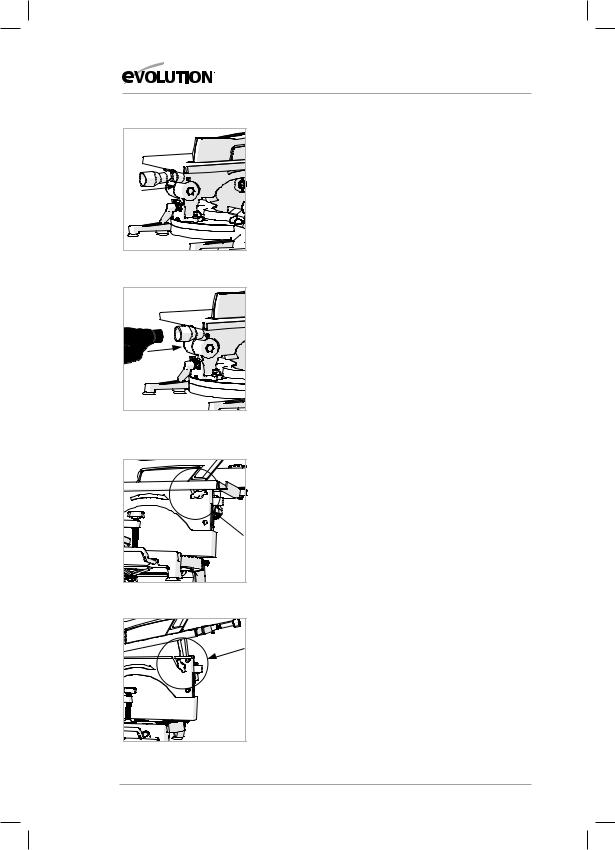
• Loosen the table height adjustment screw. (Fig.4)
• Raise the table top to its upmost position and tighten the
height adjustment screw. (Fig. 5)
• Slightly push down on the Cutting Head Handle.
• Pull out the Cutting Head Latching Pin and allow the Cutting
Head to rise to its upmost position. (Fig. 6)
• Remove the Auxiliary Lower Blade Guard and store safely for
future use.
The Fury6 is now ready to use as a Mitre Saw. (Fig. 7) |
Fig. 7 |
WORKPIECE SUPPORTS (Fig. 8)
Workpiece supports can be fitted to both sides of the machine base if required.
•Loosen the relevantWorkpiece Retaining Screw located in a socket at the top front of the machine base.
•Insert theWorkpiece Support into the holes machined in the base.
Note: The Workpiece Support should be pushed ‘fully home’ |
Fig. 8 |
|
|
into the machine base. |
|
Correct installation will require approximately 65mm of the |
|
Workpiece Support to slide into the machine base. |
|
•Fasten theWorkpiece Support into the base by tightening the Retaining Screw.
Workpiece Supports can be very useful in providing extra support for long workpieces when using the Fury6 in Mitre Saw configuration.
19
EN
DE
FR
TR

www.evolutionpowertools.com
|
HOLD DOWN CLAMP (Fig. 9) |
|
A Hold Down clamp is supplied with the Fury6. |
|
Two sockets (one on either side) are incorporated into the rear |
|
of the machines fence. |
|
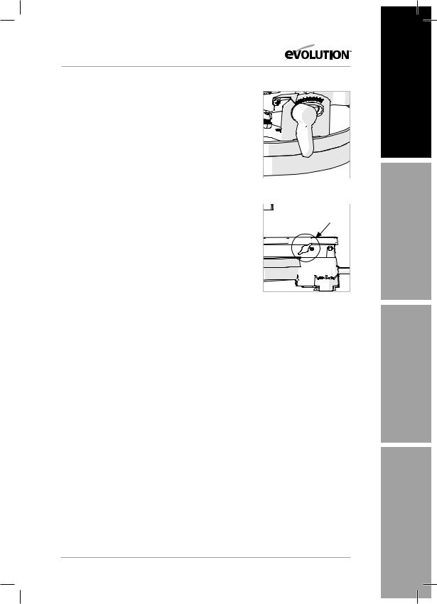
• Fit the pillar of the clamp into the socket that best suits the |
|
cutting application, ensuring that it is pushed fully down. |
|
• Tighten the fence thumbscrew to lock the pillar of the Hold |
Fig. 9 |
Down Clamp into the fence socket. |
•Putthe workpiece ontothe rotarytableandagainstthe fence.
•Adjust the Hold Down Clamp so that it securely holds the workpiece to the rotary table.
•Before attempting any cutting check to ensure that the clamp does not interfere with the blade path as the Cutting Head is lowered.
OPERATING INSTRUCTIONS
MITRE SAW CONFIGURATION
WARNING: It is important that the operator is adequately trained in the use, adjustment and operation of the machine, and has read the Instruction Manual before commencing operations.
Note: We recommend that when the Fury6 is being used as a Mitre Saw, the complete Fence Assembly is removed from the machine as stored safely for future use.
1. Releasing the Cutting Head
Note: When configured in Mitre Saw mode the Cutting Head will be automatically locked in its upper position with the Retractable Lower Blade Guard completely covering the blade teeth.
To release the Cutting Head press and hold the Cutting Head
Release Lever.
Gently press down on the Cutting Head Handle to lower the
Cutting Head. The operation of the Retractable Lower Blade
Guard is automatic.
Note: We recommend that when the machine is not in use the
Cutting Head is locked in its down position, with the Auxiliary
Lower Blade Guard correctly installed and the Cutting Head
Latching Pin fully engaged in its socket.
20
www.evolutionpowertools.com
2. Preparing to make a cut
•Avoidawkwardoperationsandhandpositionswhereasudden slip could cause fingers or hands to move into the blade.
•Cut only one workpiece at a time.
•Clear everything except the workpiece and related support devices away from the blade before commencing operations.
•Fasten the workpiece using clamp(s) to hold the workpiece securely to the table and fence.
3. Body and Hand position (Fig. 10)
•Never place hands within the‘no hands zone’(at least
150mm away from the blade). Pictograms on the machines rotary table are provided as an aid to safe working practices. Keep hands away from the path of the blade.
•Hold the workpiece firmly to the fence to prevent any movement. Use a Hold Down Clamp if possible but check that it is positioned that it does not interfere with the path of the blade or other moving machine parts.
•Before attempting a cut, make a‘dry run’with the power off so that you can see the path of the blade.
•Keep hands in position until the ON/OFF trigger has been released and the blade has completely stopped.
4. The Mitre Saw On/Off Trigger Switch Operation (Fig. 11a)
The On/Off Switch is a non-latching trigger type switch which is ergonomically located on the inside of the Cutting Head Handle.
Operate the switch to turn on the machines motor. Release the switch to turn off the machines motor.
Note: The Cutting Head cannot be lowered until the Cutting Head Release Lever is operated. (Fig. 11b) The Blade will remain covered by the retractable guard until the Cutting Head is released. Operation of the Retractable Guard is automatic.
5. Chop Cutting
The Cutting Head is gently pushed down to cut through the workpiece.
•Place the workpieceontheRotaryTable andagainst the fence in the desired position. Secure with clamp(s) as appropriate.
•Grasp the Cutting Handle.
•Turn on the motor using the trigger switch and allow the blade to reach full operating speed.
|
EN |
280mm |
|
No-Hands Zone |
No-Hands Zone |
Fig. 10 |
DE |
|
|
B |
A |
Fig. 11a + 11b |
FR
TR
21

www.evolutionpowertools.com
• |
• |
• |
• |
Fig. 12
Press and hold the Cutting Head Release Lever to release the
Cutting Head.
Gently lower the Cutting Head to its lowest position, cutting through the workpiece.
After the cut is completed, turn off the motor by releasing the trigger switch. Allow the blade to come to a complete stop. Allow the Cutting Head to rise to its upper position.
Only remove your hands or the workpiece from the machine when the Cutting Head is in its upper position with the blade teeth completely covered by the Retractable Blade Guard.
6. Mitre Cutting
Any angle from 45˚ left to 45˚ right is available, and a protractor scale can be found to the front of the Rotary Table.
Positive stops are provided for every 5˚ of angular movement.
Note: The rotary table must always be locked into position with the Mitre Angle Locking Screw even if a positive stop is selected.
To select a Mitre Angle:
•Loosen the Mitre Angle Locking Screw. (Fig.12) This is found at the front RH side of the table near the 30˚ index mark.
•Turn the RotaryTable to the required angle.To aid setting, an index mark is machined into the table just in front of the table insert.
•Tighten the Mitre Angle Locking Screw securely when the desired angle has been selected.
A Mitre Cut can now be made using the same techniques as previously described in Chop Cutting.
22
www.evolutionpowertools.com
7. Bevel Cutting
The Cutting Head can be set at any angle up to 45˚ to the Left
Hand side only.
The Bevel Locking Lever is found at the rear of the machine.
A protractor guide and pointer are incorporated into the bevel mechanism to aid setting. (Fig.13)
To set a Bevel Angle: |
|
|
Fig. 13 |
||
• Loosen the Bevel Lock Handle |
||
• Tilt the Cutting Head to the desired angle. Use the protractor |
|
|
guide to aid with setting. |
|
|
|
||
• Ensure that the Bevel Lock Handle is securely tightened |
|
|
when the desired angle has been achieved. |
|
A Bevel Cut can now be made using the same techniques as previously outlined.
Note: Always make a ‘dry run’ with the machine switched ‘off’ so that the path of the blade can be checked. Some Bevel
and Compound Cuts may require the Hold Down Clamp to
be positioned to the RH side of the Cutting Head. This may be Fig. 14 necessary to avoid interference with the blade and other parts
of the machine as the Cutting Head is lowered.
8. Fence Adjustment
Note: The left hand side of the fence is provided with additional adjustments. The upper portion of the fence can slide to the left to provide clearance for the blade. This may be necessary when acute bevel angles are selected.
To adjust the fence:
•Loosen the thumbscrew. (Fig 14)
•Slide the upper portion of the fence to the required position and tighten the thumbscrew.
•LowertheCuttingHead tocheckthepath of theblade. Ensure there is no interference with any other parts of the machine.
9. Compound Cutting
A Compound Cut is a combination of a Mitre Cut and Bevel Cut.
•Set the Mitre Angle required as previously described.
•Set the Bevel Angle as previously described.
•Ensure the tightness of all adjustment/locking screws, and conduct a ‘dry run’ to check the path of the blade.
•Make the cut as previously described.
23
EN
DE
FR
TR

Fig. 15
Fig. 16
Fig. 17
Fig. 18
www.evolutionpowertools.com
10. Cutting Bowed Material (Fig 15)
Before cutting any workpiece, check to see if it is bowed. If it is bowed the workpiece must be positioned and cut as shown. Do not position the workpiece incorrectly or cut the workpiece without the support of the fence.
11. Clearing Jammed Material
•Turn mitre saw“OFF”and allow the blade to come to a complete halt.
•Ifpossible allowthe CuttingHeadto riseto itsupperposition.
•Unplug the Mitre Saw from the mains supply.
•Carefully remove any jammed material from the machine.
TO CONFIGURE THE FURY6
FOR USE AS A TABLE SAW
WARNING: Do not cut metal or metallic materials when the machine is configured as a Table Saw.
WARNING: Only carry out this procedure with the machine disconnected from the power supply.
Caution: The Fury6 has many built in safety features and safety interlocks. It is important that the following instructions, and those found on the label attached to the machine table are read, understood and acted upon. Failure to carry out the configuration procedure could result in damage to the machine and/or injury to the operator.
•Ensure that the RotaryTable is set at 0˚ Mitre angle and the
Cutting Head is set at 0˚ Bevel angle.
•Position the Auxiliary Lower Blade Guard on the RotaryTable over the table insert and straddling the Fence. (Fig. 16)
•Lower the Cutting Head to the fully down position,‘capturing’ the Lower Auxiliary Blade Guard. Push the Cutting Head Latching Pin into its socket. (Fig. 17)
•Loosen theTable Height Adjustment Screw (Fig.18) and lower the table to its lowest position.
•Tighten the Height Adjustment Screw.
The Fury6 is now ready to use as a Table Saw.
24

www.evolutionpowertools.com
FENCE ASSEMBLY (Fig. 19)
The Fence Assembly consists of two (2) main parts:
•The Angle Gauge.
•The Rip Fence Face Plate.
Note: The‘T’slot in the Rip Fence Face Plate is not centrally located.
•Slide the Rip Fence Face Plate onto the two (2) mounting screws found on the Angle Plate.
•Ensure that the wider (20mm) portion of the Fence Face is downwards and will lie on the saw table when in use.
The Angle Plate can now be slid into the Rip Fence channel found at the front of the machine table. (Fig. 20)
Slide in from the Right Hand side ensuring that the Locking Clamp engages correctly with the front face of the Rip Fence channel.
FENCE ASSEMBLY AS A RIP FENCE
To use the Fence Assembly as a Rip Fence the Face Plate must be accurately aligned with the blade.
WARNING: Only carry out this procedure with the machine disconnected from the power supply.
To Align the Rip Fence:
•Ensurethatthetableisatitslowestsetting(see Fig. 23a &23b)
•Set the Angle Gauge to an indicated 90˚.
•Slide the Fence Assembly up to the blade, raising the Blade
Guard by hand so that the Face Plate rests alongside the blade and underneath the Blade Guard. (Fig.21)
•Gently tighten the Angle Gauge Locking Clamp Screw to lock the Assembly into the Rip Fence channel.
•Check that the Face Plate isin exact alignment with the blade.
•If adjustment is required, loosen slightly the Angle
Clamping Screw and adjust the Angle Gauge until exact alignment is achieved.
•Tighten the Angle Clamping Screw.
•Adjust the Angle Gauge Pointer if necessary to point exactly to the 90˚ index mark.
•Use a #2 Phillips Head screwdriver to loosen the Angle
Pointer fixing screw. (Fig. 22) Adjust the pointer to suit and then retighten the fixing screw.
•Loosen the Angle Clamp Locking Screw to allow the
Assembly to slide along the Rip Fence channel.
EN
height
Fig. 19
DE
Fig. 20
FR
Fig. 21
TR
Fig. 22
25

Fig. 23a
Fig. 23b
Fig. 24
www.evolutionpowertools.com
Basic Table Saw Operations
WARNING: Do not cut metal or metallic materials when the machine is configured as a Table Saw.
WARNING: Never attempt freehand cuts on this machine. Always use a correctly adjusted Rip Fence to minimise the possibility of the blade binding and kickback.
1. Adjusting the Table Height (Fig. 23a &23b)
The height of the Table above the machines motor can be adjusted. This enables your Fury6 to mimic the rise and fall facility found on many conventional table saws. The cutting depth of the blade can thereby be adjusted from 0mm to 32mm.
WARNING: Only adjust the height of the table with the machine disconnected from the mains power supply.
To adjust:
•Loosen the Height Adjustment Screw and adjust the table height so that the saw blade protrudes through the table by the required amount. Retighten the screw.
•We recommend that the saw blade protrudes through the material to be cut by approximately 3mm.
WARNING: This machine is not suitable for cutting rebates or stopped grooves.
Note: A workshop dust extraction device can be connected to the extraction port found at the rear of the machine if required.
2. Table Saw On/Off Switches (Fig. 24)
The On/Off Switch is a two (2) button latching type. The buttons are located on the Front Left Hand side of the Cutting Handle.
•Push the Green (I) button to start the motor.
•Push the Red (O) button to stop the motor.
3. Rip cutting
Note: The Fury6 in Table Saw mode is optimally suited for the cutting of thin sheet material such as laminate flooring etc.
Rip cutting is cutting along the length of a piece of material rather than across it.
26

www.evolutionpowertools.com |
|
|
|
|
|
Rip cutting should always be done with the Rip Fence set to the |
|
|
|
|
|
desired width and on the RH side of the machines table. |
|
|
Note: Check that the Rip Fence is locked in position and is |
|
|
parallel to the saw blade. Check that the riving knife is properly |
|
|
aligned with the saw blade. |
|
|
When ripping small section material a Push Stick should be |
|
|
used to feed/guide the final 300mm of the material past the |
|
|
blade. A Push Stick should always be used when making cuts of |
|
|
Fig. 25 |
|
|
less than 300mm. |
|
|
Note: A Push Stick (Fig. 25) is provided with the Fury6 and has |
|
|
a dedicated storage position to the front of the machine. |
|
|
We recommend that when not in use the Push Stick is stored on |
|
|
the machine. |
|
|
When ripping long boards or large panels always use a remote |
|
|
work support or enlist competent trained help. |
|
|
Feed the workpiece through the saw keeping it indexed against |
|
|
the Rip Fence. Use smooth, steady pressure and employ a Push |
|
|
Stick when necessary. |
|
|
Hands should never be in line with the blade. |
|
|
MAINTENANCE AND ADJUSTMENTS
WARNING: Ensure that the machine is disconnected from
the mains supply before any maintenance tasks or adjustments are attempted.
Cleaning
After each use the machine should be cleaned. Remove all sawdust etc from the visible parts of the machine with a vacuum cleaner. A vacuum cleaner can also be connected to the machine dust extraction port at the rear of the machine. This should remove debris from the inside of the machine. Never use solvents to clean plastic parts, as solvents can damage them. Clean only with a soft slightly damp cloth.
27
EN
DE
FR
TR
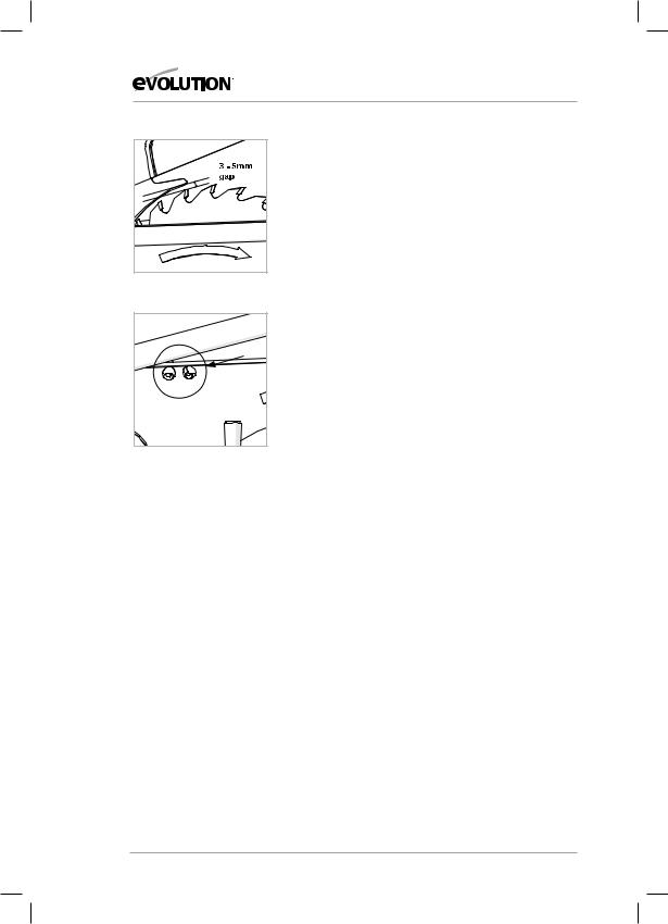
Fig. 26
Fig. 27
www.evolutionpowertools.com
Riving Knife
The Riving Knife is a very important component and comes factory fitted and correctly aligned and adjusted. The Riving Knife prevents the work from binding as it passes through the blade. Inspect the Riving Knife at regular intervals and replace it if it is worn or damaged.
The Riving Knife should be adjusted so that the gap between the tips of the blade teeth and the edge of the Riving Knife is approximately 3-5mm. (Fig.26)
To adjust the Riving Knife loosen the two (2) fixing screws (Fig. 27) slightly using an allen key. When correct alignment is achieved tighten the fixing screws.
Note: Use only a genuine Evolution Riving Knife, as this is a dedicated component for this machine. Non genuine parts could be dangerous. If in any doubt, please contact the Helpline.
Push Stick
A plastic push stick is provided with the machine. When not in use store the push stick on the machine.
Note: If the push stick becomes damaged it should be replaced. If the operator makes their own push stick, we recommend that it follows the same pattern as that supplied. Replacement push sticks are available from Evolution Power Tools.
INSTALLING or REMOVING a BLADE
WARNING: Only use genuine Evolution blades which are designed for use in this machine. Ensure that the maximum speed of the blade is compatible with the machine. Only perform this operation with the machine disconnected from the mains supply.
Note: It is recommended that the operator considers wearing protective gloves when handling the blade during installation or when changing the machines blade.
Note: The blade is a very precise fit within the Fury6 machine. Be patient and methodical when changing the blade.
28

www.evolutionpowertools.com
To change a blade:
•Ensure that the machine is in Mitre Saw Mode with the
Cutting Head in its upper position.
• Release the Retractable Lower Guard Operating Lever by
removing and safely storing its pivot screw. (Fig. 28)
• Usethepinspanner(provided)to hold the outer bladeflange.
• Usethehexkey(provided)tounscrewthearborscrew.(Fig. 29)
Note: The arbor screw has a Left Hand thread. Turn clockwise to undo and counterclockwise to tighten.
Fig. 28
• Remove the arbor screw, washer and outer blade flange.
• Manually operate the Lower Blade Guard and retract it fully up into the body of the machine
• Remove the blade by withdrawing it outwards to clear the end of the arbor and then downwards and forwards away from the machine.
Note: The 5mm blade slot at the lower front of the Cutting Head (Fig. 30) provides extra clearance when manoeuvring the blade into or out of the machine.
To refit: |
Fig. 29 |
•Ensure that the blade is suitable for this machine.
•Ensure that the direction of rotation arrow on the blade matches the direction of rotation arrow found on the machines Side Blade Guard. The blade teeth should always
point downward at the front of the saw.
•Usingthebladeslottoprovidemaximumclearanceandaccess to the machine, carefully and gently manoeuvre the blade up
into the machine and locate it on the inner blade flange.
•Reinstall the outer blade flange, washer and arbor screw.
•Hand tighten the assembly.
•Hold the outer blade flange with the pin spanner.
• Tighten the arbor screw with the hex key. |
Fig. 30 |
•Check that the blade spins freely by rotating it by hand.
•Close the Retractable Blade Guard around the blade so the blade teeth are completely covered.
•Re-connect the Retractable Blade Guard Operating Lever to its service position using the pivot screw.
•Check the installation, particularly for the operation of all the safety guards.
29
EN
DE
FR
TR

www.evolutionpowertools.com
CHECKING AND SETTING OF BEVEL ANGLES
WARNING: Before making any adjustments ensure that the machine is disconnected from the power supply.
Note: While all angular settings have been factory set, checking and adjustment may be required as a consequence of normal operational wear and tear.
Fig. 31 |
Note: To check and adjust the Bevel Angles the machine must be |
in Mitre Saw configuration. |
0˚ BEVEL ANGLE
At 0˚ Bevel Angle the blade should be perpendicular and at exactly 90˚ to the Rotary Table. An accurate engineers square (not supplied) is needed to check the 0˚ Bevel Angle.
To check:
•EnsurethattheCuttingHeadisintheverticalposition,againstits stop with the Bevel Pointer indicating 0˚ Bevel Angle.
•Tighten the Bevel Lock Handle.
•LowertheCuttingHead toitslowestposition.TheRetractable
Lower Blade Guard will rotate up into the machine.
•The engineers square can now be used to check the angle between the blade and the Rotary Table.
If adjustment is required:
Note: The Cutting Head will need to be tilted to gain access to the 0˚ Bevel Stop Adjustment Screw.
•Loosen slightly the 0˚ Bevel Stop Adjustment Screw locknut.
(Fig. 31)
•Use an Allen Key to turn the Bevel Stop Screw clockwise or counterclockwise as required.
•When exact alignment between the
blade and Rotary Table is achieved, tighten the locknut.
45˚ BEVEL ANGLE
The 45˚ Bevel Angle can be checked in a similar manner to the 0˚ Bevel Angle. An accurate 45˚ Engineers Set Square
(not supplied) will be required.
30
 Loading...