


EN

 SAW355
 SAW380
Original Instructions
ES
FR
|
|
|
|
|
|
|
|
|
|
|
|
Written in UK English |
Date Published: 01 / 02 / 2017 |
||||


ENGLISH
Original Instructions
EN
ES
FR

|
|
www.evolutionpowertools.com |
|
|
|
|
|
TABLE OF CONTENTS |
|
|
|
|
|
|
|
English |
|
Page 2 |
|
Español |
|
Página 24 |
|
Français |
|
Page 48 |
|
|
|
|
|
INTRODUCTION |
|
|
|
Guarantee |
|
Page 5 |
|
Machine Specifications |
|
Page 6 |
|
Vibration |
|
Page 7 |
|
Labels and Symbols |
|
Page 7 |
|
Intended use of this Power Tool |
|
Page 8 |
|
Prohibited use of this Power Tool |
|
Page 8 |
|
|
|
|
|
SAFETY PRECAUTIONS |
|
|
|
Electrical Safety |
|
Page 9 |
|
Outdoor Use |
|
Page 9 |
|
General Power Tool Safety Instructions |
|
Page 9 |
|
Additional Safety Instructions |
|
Page 11 |
|
|
|
|
|
GETTING STARTED |
|
|
|
Unpacking |
|
Page 13 |
|
Machine Overview |
|
Page 14 |
|
Assembly and Preparation |
|
Page 15 |
|
Operating Instructions |
|
Page 19 |
|
|
|
|
|
MAINTENANCE |
|
|
|
Environmental Protection |
|
Page 21 |
|
|
|
|
|
DECLARATION OF CONFORMITY |
|
Page 22 |
|
4

www.evolutionpowertools.com |
|
|
|
|
|
|
|
|
|
|
|
|
|
|
|
|
|
|
|
|
|
|
|
|
|
|
|
|
|
|
|
|
|
|
|
|
|
|
|
|
|
|
|
|
|
|
|
|
|
|
|
|
|
|
|
|
|
|
|
|
|
|
(1.2) THIS INSTRUCTION MANUAL |
(1.5) Evolution Power Tools will, within |
|
|
|
|
|
|
|
WAS ORIGINALLY WRITTEN IN ENGLISH |
the guarantee period, and from the original |
|
|
|
|
|
|
|
|
date of purchase, repair or replace any |
|
EN |
|
|
|
||
(1.3) IMPORTANT |
goods found to be defective in materials or |
|
|
|
|
|
|
|
Please read these operating and safety |
workmanship. This guarantee is void if the |
|
|
|
|
|
|
|
instructions carefully and completely. |
tool being returned has been used beyond the |
|
|
|
|
|
|
|
For your own safety, if you are uncertain |
recommendations in the Instruction Manual or |
|
|
|
|
|
|
|
about any aspect of using this equipment |
if the machine has been damaged by accident, |
|
|
|
|
|
|
|
please access the relevant Technical Helpline, |
neglect, or improper service. |
|
|
|
|
|
|
|
the number of which can be found on the |
|
|
|
|
|
|
|
|
Evolution Power Tools website. We operate |
This guarantee does not apply to machine’s |
|
|
|
|
|
|
|
several Helplines throughout our worldwide |
and / or components which have been altered, |
|
|
|
|
|
|
|
organization, but Technical help is also |
changed, or modified in any way, or subjected |
|
|
|
|
|
|
|
available from your supplier. |
to use beyond recommended capacities |
|
|
|
|
|
|
|
|
and specifications. Electrical components |
|
|
|
|
|
|
|
WEB |
are subject to respective manufacturers’ |
|
|
|
|
|
|
|
www.evolutionpowertools.com |
warranties. All goods returned defective shall |
|
|
|
|
|
|
|
|
be returned prepaid freight to Evolution Power |
|
|
|
|
|
|
|
(1.4) Congratulations on your purchase of |
Tools. Evolution Power Tools reserves the right |
|
|
|
|
|
|
|
an Evolution Power Tools Machine. Please |
to optionally repair or replace it with the same |
|
|
|
|
|
|
|
complete your product registration ‘online’ |
or equivalent item. |
|
|
|
|
|
|
|
as explained in the A4 online guarantee |
|
|
|
|
|
|
|
|
registration leaflet included with this machine. |
There is no warranty – written or verbal – |
|
ES |
|
|
|
||
You can also scan the QR code found on the |
for consumable accessories such as (following |
|
|
|
|
|
|
|
A4 leaflet with a Smart Phone. This will enable |
list not exhaustive) blades, cutters, drills, |
|
|
|
|
|
|
|
you to validate your machine’s guarantee |
chisels or paddles etc. In no event shall |
|
|
|
|
|
|
|
period via Evolutions website by entering your |
Evolution Power Tools be liable for loss or |
|
|
|
|
|
|
|
details and thus ensure prompt service if ever |
damage resulting directly or indirectly from |
|
|
|
|
|
|
|
needed. We sincerely thank you for selecting |
the use of our merchandise or from any other |
|
|
|
|
|
|
|
a product from Evolution Power Tools. |
cause. Evolution Power Tools is not liable |
|
|
|
|
|
|
|
|
for any costs incurred on such goods |
|
|
|
|
|
|
|
EVOLUTION LIMITED GUARANTEE |
or consequential damages. |
|
|
|
|
|
|
|
Evolution Power Tools reserves the right |
|
|
|
|
|
|
|
|
|
|
|
|
|
|
|
|
|
to make improvements and modifications |
No officer, employee or agent of Evolution |
|
|
|
|
|
|
|
to the product design without prior notice. |
Power Tools is authorized to make oral |
|
|
|
|
|
|
|
|
representations of fitness or to waive any |
|
|
|
|
|
|
|
Please refer to the guarantee registration |
of the forgoing terms of sale and none |
|
|
|
|
|
|
|
leaflet and/or the packaging for details of |
shall be binding on Evolution Power Tools. |
|
|
|
|
|
|
|
the terms and conditions of the guarantee. |
|
|
|
|
|
|
|
|
|
Questions relating to this limited guarantee |
|
|
|
|
|
|
|
|
should be directed to the company’s head |
|
|
|
|
|
|
|
|
office, or call the appropriate Helpline number. |
|
|
|
|
|
|
|
|
|
|
|
FR |
|
|
|
|
5

www.evolutionpowertools.com
|
|
|
|
|
SAW355 |
|
|
SAW380 |
|||
|
|
|
|
|
|||||||
|
|
|
|
355mm (14”) STEEL |
|
380mm (15”) STEEL |
|||||
|
|
|
|
CUTTING CHOP SAW |
|
CUTTING CHOP SAW* |
|||||
|
|
|
|
|
|
|
|
|
|
|
|
MACHINE SPECIFICATIONS |
|
|
|
METRIC |
IMPERIAL |
|
|
|
METRIC |
IMPERIAL |
|
|
|
|
|
|
|
|
|
|
|
|
|
Motor UK (230-240V ~ 50 Hz) |
|
|
|
2200W |
10A |
|
|
|
2200W |
10A |
|
|
|
|
|
|
|
|
|
|
|
|
|
Motor UK (110V ~ 50 Hz) |
|
|
|
1800W |
16A |
|
|
|
1800W |
16A |
|
|
|
|
|
|
|
|
|
|
|
|
|
Motor USA (120V ~ 60 Hz) |
|
|
|
1800W |
15A |
|
|
|
1800W |
15A |
|
|
|
|
|
|
|
|
|
|
|
|
|
Horsepower |
|
|
|
2.4 |
2.4 |
|
|
|
2.4 |
2.4 |
|
|
|
|
|
|
|
|
|
|
|
|
|
Speed (No Load) |
|
|
|
1450min-1 |
1450rpm |
|
|
|
1450min-1 |
1450rpm |
|
Weight |
|
|
|
28kg |
62lb |
|
|
|
28kg |
62lb |
|
|
|
|
|
|
|
|
|
|
|
|
|
|
|
|
|
|
|
|
|
|
|
||
CUTTING CAPACITIES |
|
|
|
METRIC |
IMPERIAL |
|
|
|
METRIC |
IMPERIAL |
|
|
|
|
|
|
|
|
|
|
|
|
|
Mild Steel Plate (Max Thickness) |
|
|
12mm |
1/2” |
|
|
|
12mm |
1/2” |
||
|
|
|
|
|
|
|
|
|
|
|
|
Square Tube at 90° (Mild Steel) |
|
|
|
120mm |
4-3/4” |
|
|
|
127mm |
5” |
|
|
|
|
|
|
|
|
|
|
|
|
|
Square Tube at 45° (Mild Steel) |
|
|
|
80mm |
3-1/8” |
|
|
|
90mm |
3-1/2” |
|
|
|
|
|
|
|
|
|
|
|
|
|
Rectangle Tube at 90° (Mild Steel) |
|
|
|
95 x 180mm |
3-3/4 x 7-1/8” |
|
|
|
95 x 200mm |
3-3/4 x 7-7/8” |
|
|
|
|
|
|
|
|
|
|
|
|
|
Rectangle Tube at 45° (Mild Steel) |
|
|
|
78 x 110mm |
3 x 4-3/8” |
|
|
|
78 x 110mm |
3 x 4-3/8” |
|
|
|
|
|
|
|
|
|
|
|
|
|
Round Tube at 90° (Mild Steel) |
|
|
|
130mm |
5-1/8” |
|
|
|
150mm |
5-7/8” |
|
|
|
|
|
|
|
|
|
|
|
|
|
Round Tube at 45° (Mild Steel) |
|
|
|
105mm |
4-1/8” |
|
|
|
127mm |
5” |
|
|
|
|
|
|
|
|
|
|
|
|
|
Wood at 90° (Nominal Size) |
|
|
|
89 x 184mm |
4 x 8” |
|
|
|
89 x 184mm |
4 x 8” |
|
|
|
|
|
|
|
|
|
|
|
|
|
Wood at 45° (Nominal Size) |
|
|
|
64 x 89mm |
3 x 4” |
|
|
|
89 x 89mm |
4 x 4” |
|
|
|
|
|
|
|
|
|
|
|
|
|
Minimum Cut Off Piece Length |
|
|
|
8mm |
5/16” |
|
|
|
8mm |
5/16” |
|
|
|
|
|
|
|
|
|
|
|
|
|
|
|
|
|
|
|
|
|
|
|||
BLADE |
|
|
METRIC |
IMPERIAL |
|
|
|
METRIC |
IMPERIAL |
||
|
|
|
|
|
|
|
|
|
|
||
Diameter |
|
|
|
355mm |
14” |
|
|
|
380mm |
15” |
|
|
|
|
|
|
|
|
|
|
|
||
Bore / Arbor |
|
|
|
25mm |
1” |
|
|
|
25mm |
1” |
|
|
|
|
|
|
|
|
|
|
|
||
Number of Teeth |
|
|
|
66 |
66 |
|
|
|
70 |
70 |
|
|
|
|
|
|
|
|
|
|
|
||
Kerf |
|
|
|
1.7mm |
.094” |
|
|
|
1.7mm |
.094” |
|
|
|
|
|
|
|
|
|
|
|
||
|
|
|
|
|
|
|
|
|
|||
NOISE & VIBRATION DATA |
|
|
|
|
|
|
|
|
|
|
|
|
|
|
|
|
|
|
|
|
|
||
Sound Pressure Level LPA |
|
|
|
108 dB (A) |
K = 3 dB(A) |
|
|
|
108 dB (A) |
K = 3 dB(A) |
|
|
|
|
|
|
|
|
|
|
|
||
Sound Power Level LWA |
|
|
|
121 dB (A) |
K = 3 dB(A) |
|
|
|
121 dB (A) |
K = 3 dB(A) |
|
|
|
|
|
|
|
|
|
|
|
||
Vibration Level |
|
|
|
1.39 m/s2 |
K = 0.5 m/s2 |
|
|
|
1.39 m/s2 |
K = 0.5 m/s2 |
|
|
|
|
|
|
|
|
|
|
|
|
|
MODEL PART NUMBERS |
|
|
|
|
|
|
|
|
|
|
|
|
|
|
|
|
|
|
|
|
|
|
|
United Kingdom |
|
|
|
230V: 080-0001 |
110V: 080-0002 |
|
|
|
230V: 080-0007 |
110V: 080-0008 |
|
|
|
|
|
|
|
|
|
|
|
|
|
United States |
|
|
|
080-0002 |
|
|
|
080-0004 |
|||
|
|
|
|
|
|
|
|
|
|
|
|
Europe |
|
|
|
080-0003 |
|
|
|
080-0009 |
|||
|
|
|
|
|
|
|
|
|
|
|
|
*Supplied with a 355mm (14”) Steel blade. To achieve maximum capacities stated, fit with a 380mm (15”) industrial saw blade.
6

www.evolutionpowertools.com |
|
|
|
|
|
|
|
|
|
|
|
|
|
|
|
|
|
|
|
|
|
|
|
|
|
|
|
|
|
|
|
|
|
|
|
|
|
|
|
|
|
|
|
|
|
|
|
|
|
|
|
|
|
|
|
|
|
|
|
|
|
|
(1.6) Note: The vibration measurement |
Handling |
|
|
|
|
|
|
|
was made under standard conditions in |
• Handlethemachinewithcare,allowing |
|
|
|
|
|
|
|
accordance with: BS EN 61029-1:2009. |
the machine to do the work. |
|
EN |
|
|
|
||
|
• Avoidusingexcessivephysicalefforton |
|
|
|
|
|
|
|
The declared vibration total value has been |
any of the machine’s controls. |
|
|
|
|
|
|
|
measured in accordance with a standard test |
• Consideryoursecurityandstability,and |
|
|
|
|
|
|
|
method and may be used for comparing one |
the orientation of the machine during use. |
|
|
|
|
|
|
|
tool with another. |
|
|
|
|
|
|
|
|
|
Work Surface |
|
|
|
|
|
|
|
The declared vibration total value may also be |
• Considertheworksurfacematerial; |
|
|
|
|
|
|
|
used in a preliminary assessment of exposure. |
its condition, density, strength, |
|
|
|
|
|
|
|
|
rigidity and orientation. |
|
|
|
|
|
|
|
(1.7) |
|
|
|
|
|
|
|
|
VIBRATION |
WARNING: The vibration emission during |
|
|
|
|
|
|
|
|
actual use of the power tool can differ from |
|
|
|
|
|
|
|
WARNING: When using this machine the |
the declared total value depending on the |
|
|
|
|
|
|
|
operator can be exposed to high levels of |
ways in which the tool is used. |
|
|
|
|
|
|
|
vibration transmitted to the hand and arm. |
|
|
|
|
|
|
|
|
|
The need to identify safety measures |
|
|
|
|
|
|
|
It is possible that the operator could develop |
and to protect the operator are based on |
|
|
|
|
|
|
|
“Vibration white finger disease” (Raynaud |
an estimation of exposure in the actual |
|
|
|
|
|
|
|
syndrome). This condition can reduce the |
conditions of use (taking account all parts |
|
|
|
|
|
|
|
sensitivity of the hand to temperature as |
of the operating cycle, such as the times the |
|
ES |
|
|
|
||
well as producing general numbness. |
tool is switched off, when it is running idle, |
|
|
|
|
|
|
|
|
in addition to trigger time). |
|
|
|
|
|
|
|
Prolonged or regular users of this machine |
|
|
|
|
|
|
|
|
should monitor the condition of their hands |
(1.8) |
|
|
|
|
|
|
|
and fingers closely. If any of the symptoms |
LABELS & SYMBOLS |
|
|
|
|
|
|
|
become evident, seek immediate |
|
|
|
|
|
|
|
|
medical advice. |
WARNING: Do not operate this machine |
|
|
|
|
|
|
|
|
if warning and/or instruction labels are |
|
|
|
|
|
|
|
• Themeasurementandassessmentof |
missing or damaged. Contact Evolution |
|
|
|
|
|
|
|
human exposure to hand-transmitted |
Power Tools for replacement labels. |
|
|
|
|
|
|
|
|
|
|
|
|
|
|||
vibration in the workplace is given in: |
|
|
|
|
|
|
|
|
BS EN ISO 5349-1:2001 and |
Note: All or some of the following symbols |
|
|
|
|
|
|
|
BS EN ISO 5349-2:2002. |
may appear in the manual or on the product. |
|
|
|
|
|
|
|
•Manyfactorscaninfluencetheactual vibration level during operation e.g. the work surfaces condition and orientation and the type and condition of the machine being used. Before each use, such factors
should be assessed, and where possible |
FR |
appropriate working practices adopted. |
|
Managing these factors can help reduce |
|
the effects of vibration: |
|
7
www.evolutionpowertools.com
(1.9)
Symbol |
Description |
|
|
V |
Volts |
|
|
A |
Amperes |
|
|
Hz |
Hertz |
|
|
Min-1 |
Speed |
|
|
~Alternating Current
no |
No Load Speed |
|
|
Wear Safety Goggles
Wear Ear Protection
Wear Dust Protection
Read Instructions
CE certification
CSA certification
Waste electrical and electronic equipment
Triman - Waste Collection
& Recycling
Warning
(1.10) INTENDED USE OF THIS POWER TOOL
WARNING: This product is a Hand Operated Chop Saw and has been designed to be used with special Evolution blades. Only use accessories designed for use in this machine and/or those recommended specifically
by Evolution Power Tools Ltd.
When fitted with an appropriate blade this machine can be used to cut:
Mild Steel
Aluminium
Wood
Stainless Steel
(1.11) PROHIBITED USE OF THIS POWER TOOL
WARNING: This product is a Hand Operated Chop Saw and must only be used as such. It must not be modified in any way, or used to power any other equipment or drive any other accessories other than those mentioned in this Instruction Manual.
(1.13) WARNING: This machine is not intended for use by persons (including children) with reduced physical, sensory or mental capabilities, or lack of experience
and knowledge, unless they have been given supervision or instruction concerning the safe use of the machine by a person responsible for their safety and who is competent
in its safe use.
Children should be supervised to ensure that they do not have access to, and are not allowed to play with, this machine.
8

www.evolutionpowertools.com |
|
|
|
|
|
|
|
|
|
|
|
|
|
|
|
|
|
|
|
|
|
|
|
|
|
|
|
|
|
|
|
|
|
|
|
|
|
|
|
|
|
|
|
|
|
|
|
|
|
|
|
|
|
|
|
|
|
|
|
|
|
|
(1.14) ELECTRICAL SAFETY |
(2.2) 1) General Power Tool |
|
|
|
|
|
|
|
This machine is fitted with the correct |
Safety Warnings [Work area safety] |
|
|
|
|
|
|
|
moulded plug and mains lead for the |
|
|
|
EN |
|
|
|
|
designated market. If the supply cord is |
a) Keep work area clean and well lit. |
|
|
|
|
|
|
|
damaged, it must be replaced by a special |
Cluttered or dark areas invite accidents. |
|
|
|
|
|
|
|
cord or assembly available from the |
b) Do not operate power tools in explosive |
|
|
|
|
|
|
|
manufacturers or its service agent. |
atmospheres, such as in the presence of |
|
|
|
|
|
|
|
|
flammable liquids, gases or dust. Power |
|
|
|
|
|
|
|
(1.15) OUTDOOR USE |
tools create sparks which may ignite the |
|
|
|
|
|
|
|
|
dust or fumes. |
|
|
|
|
|
|
|
WARNING: For your protection if this tool is to |
c) Keep children and bystanders away while |
|
|
|
|
|
|
|
be used outdoors it should not be exposed to |
operating power tool. Distractions can cause |
|
|
|
|
|
|
|
rain, or used in damp locations. Do not place |
you to lose control. |
|
|
|
|
|
|
|
the tool on damp surfaces. Use a clean, dry |
|
|
|
|
|
|
|
|
workbench if available. For added protection |
(2.3) 2) General Power Tool Safety |
|
|
|
|
|
|
|
use a residual current device (R.C.D.) that will |
Warnings [Electrical Safety] |
|
|
|
|
|
|
|
interrupt the supply if the leakage current to |
|
|
|
|
|
|
|
|
earth exceeds 30mA for 30ms. Always check |
a) Power tool plugs must match the outlet. |
|
|
|
|
|
|
|
the operation of the residual current device |
Never modify the plug in any way. Do not use |
|
|
|
|
|
|
|
(R.C.D.) before using the machine. |
any adapter plugs with earthed (grounded) |
|
|
|
|
|
|
|
|
power tools. Unmodified plugs and matching |
|
|
|
|
|
|
|
If an extension cable is required it must be a |
outlets will reduce the risk of electric shock. |
|
|
|
|
|
|
|
suitable type for use outdoors and so labelled. |
b) Avoid body contact with earthed or |
|
ES |
|
|
|
||
The manufacturer’s instructions should be |
grounded surfaces, such as pipes, radiators, |
|
|
|
|
|
|
|
followed when using an extension cable. |
ranges and refrigerators. There is an |
|
|
|
|
|
|
|
|
increased risk of electric shock if your body |
|
|
|
|
|
|
|
(2.1) POWER TOOL GENERAL |
is earthed or grounded. |
|
|
|
|
|
|
|
SAFETY INSTRUCTIONS |
c) Do not expose power tools to rain or wet |
|
|
|
|
|
|
|
(These General Power Tool Safety Instructions |
conditions. Water entering a power tool will |
|
|
|
|
|
|
|
are as specified in BS EN 60745-1:2009 |
increase the risk of electric shock. |
|
|
|
|
|
|
|
& EN 61029-1:2009). |
d) Do not abuse the cord. Never use the cord |
|
|
|
|
|
|
|
|
for carrying, pulling or unplugging the power |
|
|
|
|
|
|
|
WARNING: Read all safety warnings and |
tool. Keep cord away from heat, oil, sharp edges |
|
|
|
|
|
|
|
|
|
|
|
|
|
|||
instructions. Failure to follow the warnings |
or moving parts. Damaged or entangled cords |
|
|
|
|
|
|
|
and instructions may result in electric shock, |
increase the risk of electric shock. |
|
|
|
|
|
|
|
fire and/ or serious injury. |
e) When operating a power tool outdoors, |
|
|
|
|
|
|
|
|
use an extension cord suitable for outdoor |
|
|
|
|
|
|
|
Save all warnings and instructions for |
use. Use of a cord suitable for outdoor use |
|
|
|
|
|
|
|
future reference. The term “power tool” in |
reduces the risk of electric shock. |
|
|
|
|
|
|
|
the warnings refers to your mains-operated |
f) If operating a power tool in a damp |
|
|
|
|
|
|
|
(corded) power tool or battery-operated |
location is unavoidable, use a residual |
|
|
|
|
|
|
|
(cordless) power tool. |
current device (RCD) protected supply. |
|
|
|
|
|
|
|
|
Use of an RCD reduces the risk of |
|
FR |
|
|
|
||
|
electric shock. |
|
|
|
|
|
|
|
9

www.evolutionpowertools.com
(2.4) 3) General Power Tool Safety
Warnings [Personal Safety].
a) Stay alert, watch what you are doing and use common sense when operating a power tool. Do not use a power tool while you are tired or under the influence of drugs, alcohol or medication. A moment of inattention while operating power tools may result in serious personal injury.
b)Use personal protective equipment.
Always wear eye protection. Protective equipment such as dust masks, non-skid safety shoes, hard hat or hearing protection used
for appropriate conditions will reduce personal injuries.
c)Prevent unintentional starting. Ensure the
switch is in the off-position before connecting to power source and or battery pack, picking up or carrying the tool. Carrying power tools with your finger on the switch or energising the power tools that have the switch on invites accidents.
d) Remove any adjusting key or wrench before turning the power tool on. A wrench or key left attached to a rotating part of
a power tool may result in personal injury. e) Do not overreach. Keep proper footing
and balance at all times. This enables better control of the power tool in unexpected situations.
f)Dress properly. Do not wear loose clothing or jewellery. Keep your hair, clothing and gloves away from moving parts. Loose clothes, jewellery or long hair can be caught in moving parts.
g)If devices are provided for the connection of dust extraction and collection facilities, ensure that these are connected and properly used. Use of dust collection
can reduce dust-related hazards.
(2.5) 4) General Power Tool Safety Warnings [Power tool use and care].
a)Do not force the power tool. Use the correct power tool for your application. The correct power tool will do the job better and safer at a rate for which it was designed.
b)Do not use the power tool if the switch does not turn it on or off. Any power tool
that cannot be controlled with the switch is dangerous and must be repaired.
c) Disconnect the power tool from the power source and/or battery pack from the power tool before making any adjustments, changing accessories, or storing power tools. Such preventative safety measures reduce the risk of starting the power
tool accidentally.
d) Store idle power tools out of the reach of children and do not allow persons unfamiliar with the power tool or these Instructions to operate the power tool.
Power tools are dangerous in the hands of untrained users.
e)Maintain power tools. Check for misalignment or binding of moving parts, breakage of moving parts and any other condition that may affect the power tools operation. If damaged, have the power tool repaired before use. Many accidents are caused by poorly maintained power tools.
f)Keep cutting tools sharp and clean.
Properly maintained cutting tools with sharp cutting edges are less likely to bind and are easier to control.
g) Use the power tool, accessories and tool bits etc. in accordance with these instructions, taking into account the working conditions and the work to be performed. Use of the power tool for operations different from those intended could result in a hazardous situation.
10
www.evolutionpowertools.com
(2.6) 5) General Power Tool
Safety Warnings [Service]
a) Have your power tool serviced by a qualified repair person using only identical replacement parts. This will ensure that the safety of the power tool is maintained.
(2.7)
HEALTH ADVICE
(3.0)
ADDITIONAL SAFETY INSTRUCTIONS
(3.1)
a) DANGER: Keep hands away from cutting area and the blade. Keep your second hand on auxiliary handle, or motor housing. If both hands are holding the saw, they cannot be cut by the blade.
b) Do not reach underneath the workpiece.
WARNING: When using this machine, dust particles may be produced. In some instances, depending on the materials you are working with, this dust can be particularly harmful.
If you suspect that paint on the surface of material you wish to cut contains lead,
seek professional advice. Lead based paints should only be removed by a professional and you should not attempt to remove it yourself. Once the dust has been deposited on surfaces, hand to mouth contact can result in the ingestion of lead. Exposure to even low levels of lead can cause irreversible brain and nervous system damage. The young and unborn children are particularly vulnerable. You are advised to consider the risks associated with the materials you are working with and to reduce the risk of exposure. As some materials can produce dust that may be hazardous to your health, we recommend the
use of an approved face mask with replaceable filters when using this machine.
You should always:
•Workinawell-ventilatedarea.
•Workwithapprovedsafetyequipment,such as dust masks that are specially designed to filter microscopic particles.
(2.8)
WARNING: The operation of any power tool can result in foreign objects being thrown towards your eyes, which could result in severe eye damage. Before beginning power tool operation, always wear safety goggles or safety glasses with side shield or a full face shield where necessary.
The guard cannot protect you from the blade below the workpiece.
c) Adjust the cutting depth to the thickness of the workpiece. Less than a full tooth of the blade teeth should be visible below the workpiece.
d) Never hold piece being cut in your hands or across your leg. Secure the workpiece to a stable platform. It is important to support the work properly to minimize body exposure, blade binding, or loss of control.
e) Hold power tool by insulated gripping surfaces when performing an operation where the cutting tool may contact hidden wiring or its own cord. Contact with a “live” wire will also make exposed metal parts of the power tool “live” and shock the operator.
f) When ripping always use a rip fence or straight edge guide. This improves the accuracy of cut and reduces the chance of blade binding.
g) Always use blades with correct size and shape (diamond versus round) of arbor holes. Blades that do not match the mounting hardware of the saw will run eccentrically, causing loss of control.
h) Never use damaged or incorrect blade washers or bolt. The blade washers and bolt were specially designed for your saw, for optimum performance and safety of operation.
i)Do not use High Speed Steel (HSS) saw blades.
j)Inspect the machine and the blade before each use. Do not use deformed,
cracked, worn or otherwise damaged blades.
11
EN
ES
FR

www.evolutionpowertools.com
k) Never use the saw without the original guard protection system. Do not lock the moving guard in the open position. Ensure that the guard operates freely without jamming.
l) Only use blades that comply with the characteristics specified in this manual.
Before using accessories, always compare the maximum allowed RPM of the accessory with the RPM of the machine.
(3.2)
Causes and operator prevention of kickback:
Kickback is a sudden reaction to a pinched, bound or misaligned saw blade, causing an uncontrolled saw to lift up and out of the workpiece toward the operator:
1. When the blade is pinched or bound tightly by the kerf closing down, the blade stalls and the motor reaction drives the unit rapidly back toward the operator.
2. If the blade becomes twisted or misaligned in the cut, the teeth at the back edge of the blade can dig into the top surface of the workpiece causing the blade to climb out of the kerf and jump back towards the operator.
(3.3)
Kickback is the result of saw misuse and/ or incorrect operating procedures or conditions and can be avoided by taking proper precautions as given below.
a) Maintain a firm grip with both hands on the saw and position your arms to resist kickback forces. Position your body to either side of the blade, but not in line with the blade. Kickback could cause the saw to jump backwards, but kickback forces can be controlled by the operator, if proper precautions are taken.
b) If the blades are binding, or when interrupting a cut for any reason, release the trigger and hold the saw motionless in the material until the blades come to a complete stop. Never attempt to remove the saw from the work or pull the saw backward while the blades are in motion or kickback may occur. Investigate and take corrective actions to eliminate the cause of blade binding.
c) When restarting a saw in the workpiece, centre the saw blade in the kerf and check that saw teeth are not engaged into the material. If saw blade is binding, it may walk up or kickback from the workpiece as the saw is restarted.
d) Support large panels to minimise the risk of blade pinching and kickback. Large panels tend to sag under their own weight. Supports must be placed under the panel on both sides, near the line of cut and near the edge of the panel.
e) Blade depth and bevel adjusting locking levers must be tight and secure before making a cut. If the blade adjustment shifts while cutting it may cause binding and kickback.
f)Do not use dull or damaged blades.
Unsharpened or improperly set blades produce a narrow kerf causing excessive friction, blade binding and kickback.
g)Use extra caution when making a “plunge cut” into existing walls or other blind areas. The protruding blade may cut
objects that can cause kickback.
h) Check lower guard for proper closing before each use. Do not operate the saw if lower guard does not move freely and close instantly. Never clamp or tie the lower guard into the open position. If saw is accidentally dropped, lower guard may be
bent. Raise the lower guard with the retracting handle (if equipped) and make sure it moves freely and does not touch the blade or any other part, in all angles and depths of cut.
12

www.evolutionpowertools.com
i) Check the operation of the lower guard spring. If the guard and the spring are not operating properly, they must be serviced before use. Lower guard may operate sluggishly due to damaged parts, gummy deposits, or a build-up of debris.
j) Lower guard may be retracted manually only for special cuts such as “plunge cuts” and “compound cuts.” Raise lower guard by retracting handle and as soon as blade enters the material, the lower guard must be released. For all other sawing, the lower guard should operate automatically.
k) Always observe that the lower guard is covering the blade before placing saw down on a bench or the floor. An unprotected, coasting blade will cause the
saw to walk backwards, cutting whatever is in its path. Be aware of the time it takes for the blade to stop after switch is released.
(3.4)
WARNING: If any parts are missing, do not operate your machine until the missing parts are replaced. Failure to follow this rule could result in serious personal injury.
(4.1)
GETTING STARTED - UNPACKING
Caution: This packaging contains sharp objects. Take care when unpacking. Remove the machine, together with the accessories supplied from the packaging. Check carefully to ensure that the machine is in good condition and account for all the accessories listed in this manual. Also make sure that all the accessories are complete. If any parts are found to be missing, the machine and its accessories should be returned together in their original packaging to the retailer.
Donotthrowthepackagingaway; keep it safe throughout the guarantee period. Dispose of the packaging in an environmentally responsible manner. Recycle if possible.
Do not let children play with empty plastic bags due to the risk of suffocation.
(4.2)
ITEMS SUPPLIED
Description |
Quantity |
|
|
|
|
Instruction Manual |
1 |
|
|
|
|
Steel Cutting Blade |
1 |
|
|
|
|
Hex Key 8mm |
1 |
|
(Blade Change) |
||
|
||
|
|
|
‘V’ Clamp Jaw |
1 |
|
|
|
(4.3)
ADDITIONAL ACCESSORIES
In addition to the standard items supplied with this machine the following accessories are also available from the Evolution online shop at www.evolutionpowertools.com or from your local retailer.
(4.4)
Description |
Part No |
|
|
Material specific cutting |
|
blades (use only Evolution |
Specific to |
Blades or Evolution approved |
blade type |
blades with this machine) |
|
|
|
13
EN
ES
FR

www.evolutionpowertools.com
MACHINE OVERVIEW
A parts diagram can be downloaded from www.evolutionpowertools.com.
4
5
1
3
7
6
2
1. |
Lower Blade Guard |
5. |
Arbor Guard |
2. |
Front Swivelling Vise Jaw |
6. |
Chip Collection Tray |
3. |
Repositionable Rear Vise Jaw |
7. |
Quick Release ‘Split Nut’ |
|
|
|
(North American Market Only). |
4.Upper Blade Guard
14
www.evolutionpowertools.com |
|
(>5.5) |
|
GETTING STARTED - PREPARATION |
|
RELEASING the CUTTING HEAD |
|
The cutting head will automatically rise to the upper position |
|
once it is released from the locked down position. |
|
To Release the cutting head from |
|
the Locked Down position: (5.5<) |
|
• Gentlypressdownonthecuttinghandle. |
Fig. 1 |
•Pullouttheheadlatchingpinandlockintheouterposition
(Fig. 1) Allow the cutting head to rise to its upper position.
If Release is Difficult: |
|
|
• Gentlyrockthecuttingheadupanddown. |
|
|
• Pullthelatchingpinfullyoutandturn1/4ofaturntolockin |
|
|
the outer position. |
|
|
Note: We recommend that when the machine is not in use the |
|
|
cutting head is locked in its down position with the latching pin |
|
|
fully engaged in its socket. |
|
|
Fig. 2 |
||
(>5.1) |
||
|
||
INSTALLING or REMOVING a BLADE |
|
|
|
||
WARNING: Only use genuine Evolution blades, or Evolution |
|
|
approved blades which are designed for this machine. Ensure |
|
|
that the maximum recommended blade speed of the blade is |
|
|
compatible with the machine. |
|
|
WARNING: Only perform this operation with the machine |
|
|
disconnected from the power supply. |
|
|
Note: It is recommended that the operator considers wearing |
|
|
Fig. 3 |
||
protective gloves when handling the blade during installation |
||
|
||
or when changing the machine’s blade. (< 5.1) |
|
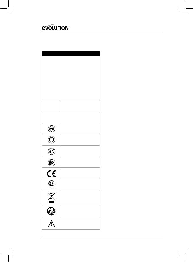
(5.6)
Removing a Blade:
• Ensure that the cutting head is in its upper position.
• Loosen the fastener screw securing the arbor guard and rotate the guard upwards to reveal the machine’s arbor. (Fig. 2)
•Engage the arbor lock by pressing the arbor lock button.
(Fig. 3)
•Use the supplied hex key to loosen the arbor screw. (Fig. 4)
Fig. 4
15
EN
ES
FR
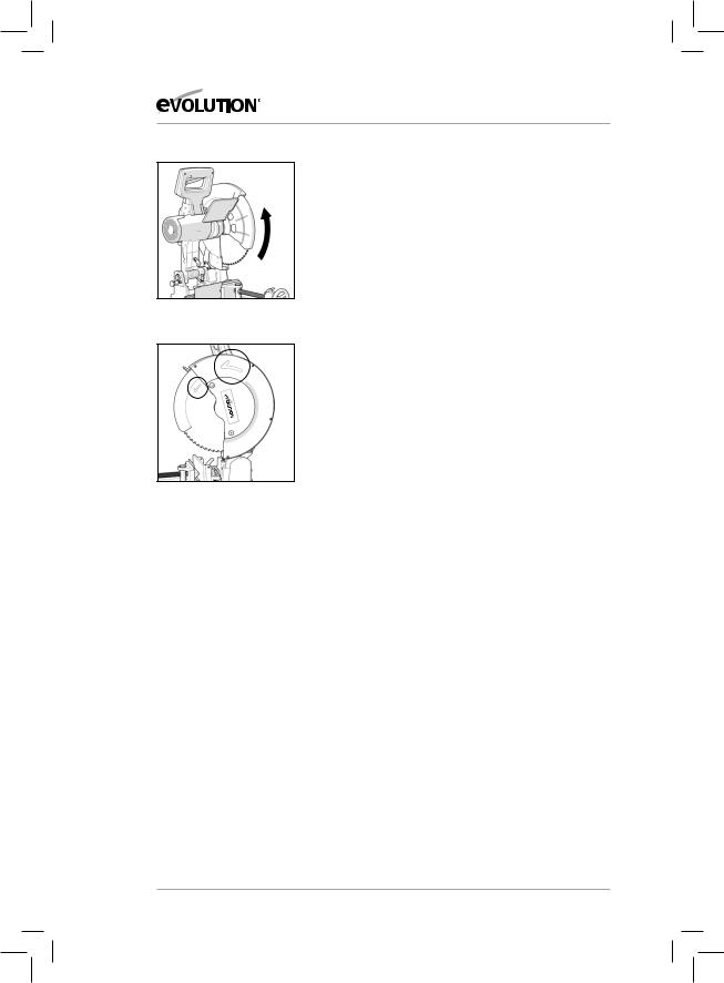
Fig. 5
Fig. 6
www.evolutionpowertools.com
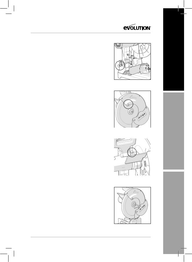
Note: The arbor screw has a right hand thread. Turn clockwise to tighten. Turn counterclockwise to loosen.
•Removethearborscrew,washerandouterbladeflangeand store safely for future installation.
•Retractthelowerbladeguardupintotheupperbladeguard by rotating it by hand. (Fig. 5)
•Removetheblade,leavingtheinnerbladeflangeinits service position.
(5.7)
Installing a Blade:
•Ensurethatallcomponentsarefreefromdirtanddebris.
•Installthebladeontotheinnerbladeflangeandarbor, ensuring that the direction and rotation arrow on the blade matches the direction of arrow rotation found on the machine’s upper blade guard. (Fig. 6)
•Reinstalltheouterbladeflange,washerandarborscrew.
•Lockthearborbypressingthearborlockbutton.
•Tightenthearborscrewusingthe8mmhexkey.
•Returnthearborguardtoitsservicepositionandtightenthe cross head screw.
•Checkthatthearborlockhasbeenreleasedbyrotatingthe blade by hand.
•Ensurethatthehexkeyisremovedfromthearborscrewand is safely stored for future use.
•Checktheinstallation,andparticularlytheoperationofthe retractable lower blade guards by lowering and raising the cutting head a few times.
(5.8 )
WARNING: After installing a new blade, always run the machine, without load, for a couple of minutes. Stand away fromtheblade.Ifthebladeweretocontainanundetectedflaw, it could shatter during this trial run.
16
www.evolutionpowertools.com
(5.9) |
|
|
|
||
CUTTING HEAD TRAVEL |
B |
|
Cutting Head Downward Travel Adjustment |
|
|
To prevent the blade from contacting any part of the |
|
|
machine’s metal base the downward travel of the |
|
|
cutting head can be adjusted. |
A |
|
|
||
Lower the cutting head and check for any blade contact with |
|
|
the machine’s base. |
|
|
Fig. 7 |
||
If the downward travel of the cutting head needs to |
||
|
||
be adjusted: |
|
|
|
•Loosenthelocknutonthedownwardtravelstopscrew.
(Fig. 7a)
•Turntheadjustingscrew(Fig. 7b) out (counter-clockwise) to decrease the downwards travel of the cutting head.
• Turntheadjustingscrewin(clockwise)toincreasethe |
|
|
downwards travel of the cutting head. |
|
|
• Tightentheadjustmentscrewlocknutwhensatisfactory |
|
|
downward travel of the cutting head is achieved. |
|
|
(5.10) |
Fig. 8 |
|
CUTTING ANGLE ADJUSTMENT |
||
|
Note: The rear vise jaw can be turned through 450.
The rear vise jaw is factory set at 00 (at 900 to the blade) so that the blade cuts squarely across material positioned in the vise. For angled cuts, the rear vise jaw can be swung through (up to) 450, with a protractor scale being included on the vise jaw for ease and accuracy of setting. (>5.10)
To angle the rear vise jaw:
•LoosentheM10socketheadedscrewandtheleverhandled locking screw. (Fig. 8)
•Turntherearvisejawtotherequiredangle.
•Tightenthesocketheadedscrewsecurelyusingthesupplied hex key and tighten the lever handled locking screw.
Note: The lever handle locking screw has a spring loaded repositionable lever. Repositioning of the lever may be necessary to ensure that the locking screw can be tightened sufficiently when the rear vise jaw is angled. To reposition the lever on the screw, pull the lever upwards and rotate the
lever to a convenient position (one that allows the screw to be tightened) release the lever and tighten the screw. The front vise jaw will automatically compensate for any set angle of the rear jaw, or to accommodate irregular shaped workpieces.
17
EN
ES
FR
www.evolutionpowertools.com
1
2
3
Fig. 9
Fig. 10
REPOSITIONING THE REAR VISE JAW
The rear vise jaw can be removed from the machine’s base and repositioned. (Fig.9)
To reposition:
•RemovetheM10socketheadedscrewandtheleverhandled locking screw and all washers that secure the rear vise jaw to the machine’s base.
•To remove the lever handled locking screw, pull the lever upwards and hold against the spring while unscrewing the locking screw from its service position using a flat bladed screwdriver.
•Repositiontherearvisejaw;therearethree(3)possible positions available because of the six (6) threaded holes in the machine’s base.
•Replaceleverhandledlockingscrewandthesocketheaded screw into their new service positions. Ensure that all standard and locking washers are correctly positioned.
Repositioning the rear vise jaw to the rear-most position will enable wider pieces of material to be cut than is possible with the rear vise jaw in either of the more forward positions.
‘V’ Clamp Jaw (If supplied)
The ‘V’ Clamp Jaw slips over the moving front vise jaw It should be used when cutting round material as it provides greater clamping security. It should also be used to cut square tube in a diamond position (Fig. 10).
18

www.evolutionpowertools.com
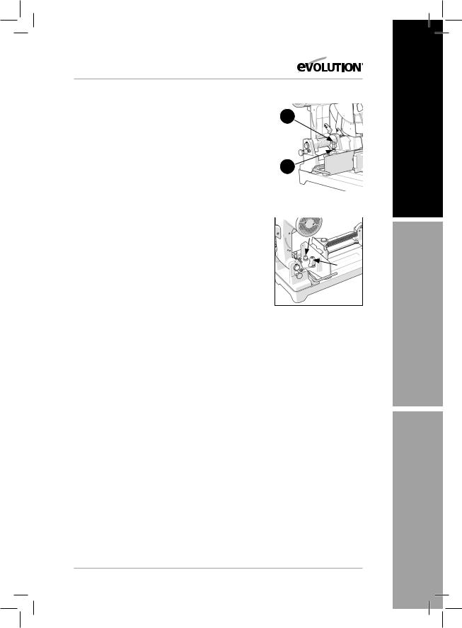
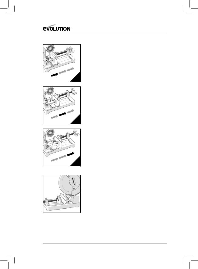
QUICK VISE ADJUSTMENT MECHANISM (NORTH AMERICAN MARKET ONLY)
For speed and convenience, the vise operating mechanism is equipped with a ‘split nut’. Using this enables rapid adjustment of the front vise jaw.
•Liftthe‘splitnut’.(Fig. 11a)
•Slidethefrontjawtotherequiredposition.
•Returnthe‘splitnut’toitsserviceposition.(Fig 11b)
WARNING: The ‘split nut’must be returned to its service position and be fully engaged with the threads on the long vise screw. Pulling back slightly on the vise handle just before the vise jaw contacts the workpiece will help the correct seating of the ‘split nut. Using this machine without the ‘split nut’fully engaged with the vise screw threads is dangerous and must not be attempted.
•Tightenthevisetosecuretheworkpiece.
•Checkthesecurityoftheworkpiecebeforeattemptingacut.
(>5.2)
OPERATING INSTRUCTIONS
PREPARING TO MAKE A CUT
Do not overreach. Keep good footing and balance. Stand to one side so that your face and body are out of line
of a possible kickback.
Caution: The minimum cut off piece must be 8mm (5/16”) or greater in length to avoid the piece falling through the blade slot and causing any potential danger. (Fig 12)
WARNING: Freehand cutting is a major cause of accidents and should not be attempted.
•Ensurethattheworkpieceisfirmlysecuredinthevise.
•Themachine’sbaseshouldbecleanandfreefromanyswarfor sawdust etc. before the workpiece is clamped into position.
•Ensurethatthe‘cut-off’materialisfreetomovesidewaysaway from the blade when the cut is completed. Ensure that the‘cut-off’ piece cannot become‘jammed’ in any other part of the machine.
•Donotusethissawtocutsmallpieces.Iftheworkpiece being cut would cause your hand or fingers to be within 150mm of the saw blade, the workpiece is too small.
Angles should be clamped in an inverted position so that the point of the section is uppermost. (<5.2)
A
EN
B
Fig. 11
ES
8mm (5/16”) +
Fig. 12
FR
19

www.evolutionpowertools.com
(5.4)
THE ON/OFF TRIGGER SWITCH
This machine is equipped with a safety start trigger switch.
To start the tool:
•Pushinthesafetylockbuttononthesideof the handle with your thumb.
•Depressthemaintriggerswitchtostartthe motor.
WARNING: Never start the saw with the cutting edge of the saw blade in contact with the workpiece surface.
(5.3)
MAKING A CUT
•Withthecuttingheadintheupperposition, switch on the motor and allow it to reach full operational speed.
•Gentlylowerthecuttinghead.
•Introducethebladeintothematerialslowly, using light pressure at first to keep the blade from grabbing.
•Graduallyincreasethepressureasablade enters the workpiece. Do not ‘force’ the machine. Let the saw blade do the work.
Note: Cutting performance will not improve by applying undue pressure on the machine, and doing so may cause blade and motor life to be reduced.
•Reducethepressureasthebladebeginsto exit the material.
•Oncompletionofacutallowthecutting head to return to its upper position, and turn off the motor.
•Onlyremoveyourhands,ortheworkpiece from the machine, after the motor has completely stopped and the stationary blade is covered by the lower blade guard.
(6)
MAINTENANCE
(6.1)
Note: Any maintenance must be carried out with the machine switched off and disconnected from the mains/battery power supply.
Check that all safety features and guards are operating correctly on a regular basis. Only use this machine if all guards/safety features are fully operational.
All motor bearings in this machine are lubricated for life. No further lubrication is required.
Use a clean, slightly damp cloth to clean the plastic parts of the machine. Do not use solvents or similar products which could damage the plastic parts.
WARNING: Do not attempt to clean by inserting pointed objects through openings in the machine’s casings etc. The machine’s air vents should be cleaned using compressed dry air.
Excessive sparking may indicate the presence of dirt in the motor or worn out carbon brushes.
(>6.2)
If this is suspected have the machine serviced and the brushes replaced by a qualified technician with Evolution recommended brushes. (<6.2)
20
www.evolutionpowertools.com
CHIP COLLECTION TRAY
The chip collection tray should be emptied at regular intervals. We recommend that for efficiency purposes the tray be emptied when it is approximately 60% full.
To check the Chip Collection Tray:
•Turnthelockinglevertothehorizontal position and withdraw the tray from the machine to check the contents.
•Emptythecontentsofthetrayintoa suitable recycling bin.
•Itmaybenecessarytowearadustmask when emptying the chip collection tray.
•Replacethechipcollectiontrayandreturnthe locking lever to the vertical position to secure the tray within the machine’s base.
(6.4)
ENVIRONMENTAL PROTECTION
Waste electrical products should not be disposed of with household waste. Please recycle where facilities exist. Check with your local authority or retailer for recycling advice.
TRANSPORTATION/STORAGE
For ease and convenience, when transporting or storing the machine, the cutting head can be held in the ‘down’ position.
To hold the cutting head down:
•Lowerthecuttingheadtoitslowestposition.
•RotatethecuttingheadLockingPin1/4of a turn and allow it to deploy to the ‘locked down’ position.
21
EN
ES
FR

www.evolutionpowertools.com
EC DECLARATION OF CONFORMITY |
SAW355 |
In accordance with EN ISO 17050-1:2004 |
|
The manufacturer of the product covered by this Declaration is:
Evolution Power Tools, Venture One, Longacre Close, Holbrook Industrial Estate, Sheffield, S20 3FR.
The manufacturer hereby declares that the machine as detailed in this declaration fulfils all the relevant provisions of the Machinery Directive and other appropriate directives as detailed below. The manufacture further declares that the machine as detailed in this declaration, where applicable, fulfils the relevant provisions of the Essential Health and Safety requirements.
The Directives covered by this Declaration are as detailed below:
2006/42/EC. Machinery Directive.
2014/30/EU. Electromagnetic Compatibility Directive. 2011/65/EU. The Restriction of the Use of certain Hazardous
Substances in Electrical Equipment (RoHS) Directive. 2002/96/EC as The Waste Electrical and Electronic Equipment (WEEE) Directive. amended by
2003/108/EC .
And is in conformity with the applicable requirements of the following documents:
EN13898:2003+A1:2009
EN 60204-1:2006+ A1:2009
EN 55014-1:2006+A1:2009+A2:2011
EN 55014-2:1997+A1:2001:A2:2008
EN 61000-3-2:2014
EN 61000-3-3:2013
Product Details |
|
Description: |
EVOSAW355 355mm (14”) STEEL CUTTING CHOP SAW |
Evolution Model No: |
080-0001 / 080-0002 / 080-0003 / 080-0003A |
Brand Name: |
EVOLUTION |
Voltage: |
230 - 240v ~ 50Hz |
Input: |
2200W |
The technical documentation required to demonstrate that the product meets the requirements of directive has been compiled and is available for inspection by the relevant enforcement authorities, and verifies that our technical file contains the documents listed above
and that they are the correct standards for the product as detailed above.
Name and address of technical documentation holder.
Signed: |
Print: Matthew Gavins - Operations Director |
Date: |
01/02/2017 |
22
 Loading...