


C-PRO KILO
PROGRAMMABLE CONTROLLERS
HARDWARE MANUAL
CODE 114CPRKHWE01

C-PRO KILO HARDWARE MANUAL
Important
Please read these instructions carefully prior to installation and use, and follow all the precautions for installation and electrical connections; keep these instructions with the device for future consultation.
The device must be disposed of in accordance with local regulations pertaining to the collection of electrical and electronic
appliances.
Page 2
C-PRO KILO HARDWARE MANUAL
Contents
1 |
INTRODUCTION ........................................................................................................................................ |
4 |
|
2 |
COMPONENTS AND ACCESSORIES..................................................................................................... |
8 |
|
|
2.1 |
EXAMPLE FOR BUILT-IN VERSIONS........................................................................................................... |
8 |
|
2.2 |
EXAMPLE FOR CLOSED CASE VERSIONS ................................................................................................... |
9 |
3 |
TECHNICAL CHARACTERISTICS ...................................................................................................... |
10 |
|
|
3.1 |
CONNECTIONS ....................................................................................................................................... |
10 |
|
3.2 |
C-PRO KILO ELECTRICAL CONNECTIONS (WIRING) ............................................................................. |
12 |
|
3.3 |
C-PRO KILO DIMENSIONS/INSTALLATION ........................................................................................... |
15 |
|
3.4 |
GENERAL CHARACTERISTICS ................................................................................................................. |
18 |
|
3.5 |
TECHNICAL CHARACTERISTICS .............................................................................................................. |
18 |
|
3.6 |
ELECTRICAL CHARACTERISTICS............................................................................................................. |
19 |
4 THE C-PRO KILO USER INTERFACE ................................................................................................ |
22 |
||
5 C-PRO EXP KILO I/O EXPANSION UNITS ........................................................................................ |
26 |
||
|
5.1 |
C-PRO EXP KILO ELECTRICAL CONNECTIONS (WIRING) ..................................................................... |
28 |
|
5.2 |
C-PRO EXP KILO DIMENSIONS/INSTALLATION ................................................................................... |
31 |
6 |
ACCESSORIES.......................................................................................................................................... |
33 |
|
|
6.1 |
USER TERMINALS (INTRABUS) .............................................................................................................. |
33 |
|
6.1.1 |
V LEDi dimensions/installation.................................................................................................... |
34 |
|
6.1.2 |
V LEDi electrical connections (wiring)........................................................................................ |
34 |
|
6.1.3 |
V LEDi user interface................................................................................................................... |
35 |
|
6.1.4 |
V WALL dimensions and installation ........................................................................................... |
36 |
|
6.1.5 |
V WALL electrical connections, when the user terminal has an independent power supply....... |
37 |
|
6.1.6 |
V WALL electrical connections, when the user terminal is powered from the controller............ |
38 |
|
6.1.7 |
V WALL user interface ................................................................................................................. |
39 |
|
6.2 |
REMOTE USER INTERFACE (CAN) ......................................................................................................... |
41 |
|
6.2.1 |
V-VIEW ........................................................................................................................................... |
41 |
|
6.3 |
EVDFAN1 PHASE CHOPPING SPEED REGULATOR .................................................................................. |
45 |
|
6.3.1 |
EVDFAN1 electrical connections (wiring) .................................................................................. |
46 |
|
6.4 |
CONTROL AND MONITORING ACCESSORIES ............................................................................................ |
47 |
|
6.4.1 |
Non-optoisolated TTL/RS-485 interface....................................................................................... |
47 |
|
6.4.2 |
Optoisolated TTL/RS-485 interface.............................................................................................. |
47 |
|
6.4.3 |
EVIF21TS7I electrical connections.............................................................................................. |
48 |
|
6.5 |
PROGRAMMING ACCESSORIES................................................................................................................ |
49 |
|
6.5.1 |
EVKEY programming key............................................................................................................. |
49 |
|
6.5.2 |
EVKEY dimensions....................................................................................................................... |
49 |
|
6.5.3 |
EVPROG programming kit........................................................................................................... |
50 |
7 |
CAN CONNECTION................................................................................................................................. |
51 |
|
|
7.1 |
NOTES ON THE PARAMETER OF THE CONTROLLER RELATIVE TO THE CAN NET CONFIGURATION......... |
52 |
Page 3
C-PRO KILO HARDWARE MANUAL
1 Introduction
The C-PRO KILO family of programmable controllers is the ideal solution for low to medium complexity refrigeration, ventilation and air conditioning applications. The controller software is fully programmable, in a simple and intuitive manner, both in terms of control and the user interface, thanks to the use of the UNI-PRO development environment.
The C-PRO KILO is available in a version for installation on DIN rails (10 DIN modules); there is also an open case version available, again for installation on DIN rails.
Using the 7 relay outputs, it is possible to control various types of devices such as compressors, water circulation pumps, de-icer heaters, condensation or evaporation fans, cycle inversion valves, alarm indicators etc.
As an alternative to the 7 electromechanical relay outputs, there is also a version with 5 electromechanical relays and 2 solid state relays (SSR).
The C-PRO KILO is also available in an 11 DIN module case; in addition to the normal features, this version also has a 48 VDC stabilised output, useful in the climate control and mobile phone control unit (shelter) sectors for supplying the shutter servomotor.
The C-PRO KILO also has 3 analogue outputs: one for controlling the EVDFAN1 phase chopping module (this output is also provided with the standard version of the controller) and two 0-10 V or 4-20 mA type outputs (available on request).
The controller has 5 analogue inputs, 3 for NTC probes and 2 for NTC probes/0-5 V ratiometric transducers (on request)/0-20 mA transducers/4-20 mA transducers.
The C-PRO KILO also has 7 digital inputs for controlling the operation of the unit.
There are two alternative versions according to the kind of Bus used: CANBus version and IntraBus version. You can also connect until two I/O expansion units (IntraBus version) or the expansions of the C-PRO EXPMICRO, C-PRO EXP-KILO, C-PRO EXP-MEGA, C-PRO EXP-GIGA families to increase the I/O (CAN version).
All parameters can be altered by means of the user interface; it is possible to download and upload configuration data using the programming key.
Finally, the controllers have a Real Time Clock.
The C-PRO KILO is available as a built-in version (with 4 x 20 character alphanumeric display, LED display with refrigeration icons or LED display with air conditioning icons) and in closed case and open case versions; the closed and open case versions have neither display nor keypad and must be used in conjunction with a remote terminal unit.
Page 4
C-PRO KILO HARDWARE MANUAL
The following table illustrates the main features of the C-PRO KILO:
|
|
|
|
|
|
|
|
|
|
Output with |
|
Dimensions |
Power |
Analogue |
Digital |
Analogue |
Analogue |
Digital |
48 VDC |
||||
outputs |
stabilised |
||||||||||
supply |
inputs |
(1) |
inputs |
output 1 |
(2) |
outputs |
(4) |
||||
|
|
|
2 and 3 (3) |
|
power |
||||||
|
|
|
|
|
|
|
|
|
|
supply |
|
|
|
|
|
|
|
|
|
|
|
|
|
10 DIN |
24 VAC/ |
|
|
|
|
|
Available on |
|
|
|
|
20 … 60 |
5 |
|
7 |
Yes |
|
7 |
|
No |
|||
modules |
|
|
request |
|
|||||||
VDC |
|
|
|
|
|
|
|
|
|||
|
|
|
|
|
|
|
|
|
|
||
|
|
|
|
|
|
|
|
|
|
|
|
11 DIN |
48 VDC |
5 |
|
7 |
Yes |
|
Available on |
7 |
|
Yes |
|
modules |
|
|
request |
|
|||||||
|
|
|
|
|
|
|
|
|
|||
|
|
|
|
|
|
|
|
|
|
|
|
(1)3 for NTC probes and 2 for NTC probes/0-5 V ratiometric transducers (on request)/0-20 mA transducers/ 4-20 mA transducers
(2)for controlling the EVDFAN1 phase chopping module (optoisolated output)
(3)0-10 V or 4-20 mA (optoisolated outputs, not available in the open case models; all three combinations are permitted)
(4)7 electromechanical relays; or alternatively, 5 electromechanical relays and 2 solid state relays (SSR).
The Real Time Clock and 48 VDC stabilised power output are not available in the open case version.
Page 5

C-PRO KILO HARDWARE MANUAL
C-PRO KILO
Built-in version with 4 x 20 character alphanumeric display
C-PRO KILO
Built-in version with LED display and air conditioning icons
Page 6

C-PRO KILO HARDWARE MANUAL
C-PRO KILO
Closed case version
C-PRO KILO
Open version
Page 7
C-PRO KILO HARDWARE MANUAL
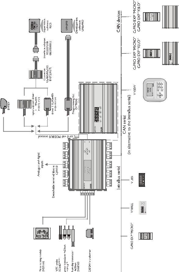
2 Components and accessories
2.1 Example for built-in versions
Page 8

C-PRO KILO HARDWARE MANUAL
2.2 Example for closed case versions
Page 9
C-PRO KILO HARDWARE MANUAL
3 Technical characteristics
3.1 Connections
Power supply:
The C-PRO KILO is powered by 24 VAC. It can also be powered using DC supplies with outputs between 20 and 60 VDC; in this case, it is not possible to control the fan and phase chopping modules. The maximum length for the power supply connecting cables is 1 m.
Connecting the analogue inputs:
The C-PRO KILO has three analogue inputs for NTC sensors, and two for NTC sensors/0-20 mA transducers/4-20m A transducers/0-5 V ratiometric transducers (on request). Selection is implemented by the UNI-PRO development system. The 0-20 and 4-20 mA transducers may be powered from the +12 V terminal, the 0-5 V ratiometric transducers from the +5 V terminal (see the physical layout). The maximum length for the analogue input connecting cables is 3 m.
Connecting the digital inputs:
The C-PRO KILO has 7 non-optoisolated digital inputs (clean contact). The maximum length for the digital input connecting cables is 3 m.
Connecting the digital outputs:
The C-PRO KILO has a maximum of 7 digital outputs to electromechanical relays (two can be SSR). The maximum length for the digital output connecting cables is 3 m.
Connecting the analogue outputs:
The C-PRO KILO has 1 pulse analogue output for driving the phase chopping modules. The maximum length for the connecting cables for this type of analogue output is 1 m.
The C-PRO KILO also has 2 voltage or current analogue outputs (optional). The maximum connecting cable length for these analogue outputs is 3 m. Optional analogue outputs are not available for the open case models.
Connecting the remote terminals (IntraBus):
The connection between the C-PRO KILO and the user terminal is made using a 3 way cable. The maximum length for remote terminal connecting cables is 1 m if powered by DC current from the controller; 30 m in the case of a wall-mounted keypad powered by a separate transformer.
Connecting the remote expansion units (IntraBus):
The connection between the C-PRO KILO and the I/O expansion units is made using a 3 way cable. The maximum length for the remote I/O expansion units connecting cables is 1 m.
User interface connections (CAN):
The connection between C-PRO KILO and the remote user interface is made using 2 way cable (better if it is two weaves couples) plus possible ground.
The maximum length of the connection cables to the remote user interface depends of the CAN port baud rate.
-1.000 m with 20.000 baud
-500 m with 50.000 baud
-250 m with 125.000 baud
-50 m with 500.000 baud.
The CAN port baud rate is settable by parameter.
Page 10
C-PRO KILO HARDWARE MANUAL
Connection with a remote expansion (or another CAN controller):
The connection between C-PRO KILO and the remote expansion (or other CAN controller) is made using a 2 way cable (better if weaved) plus possible ground.
The maximum length of the connection cables to the remote controllers or expansions depend on the CAN port baud rate (see above section “User interface connec tions”).
Notes on the electrical connections:
-do not use electric or pneumatic screw-wrenches on the terminal board
-if the device has been moved from a cold to a warm environment, condensation may have formed inside; please wait approx. one hour prior to switching on
-ensure that the voltage, frequency and operational power of the device are compatible with the local power supply
-disconnect the power prior to proceeding with any kind of maintenance operation
-do not use the device as a safety device
-for repairs and any information relating to the device, contact the Evco dealer network.
Caution
The indications regarding maximum connecting cable length infer that a series of precautions are complied with:
To avoid immunity problems, it is good practice to observe the following points:
-Avoid locations with antennae
-Avoid cabling probe inputs and relay outputs together; more generally, avoid mixing low and high voltage signals with one another
-Avoid wrapping cable around power components
To avoid any safety issues, it is good practice to observe the following points:
-Avoid premises with relative humidity >90%
-Avoid moisture
-Avoid corrosive environments
-Avoid explosive environments
Strategies
Finally, ensure that the operating conditions are within the operating limits indicated in the technical characteristics.
Page 11

C-PRO KILO HARDWARE MANUAL
3.2 C-PRO KILO electrical connections (wiring)
The C-PRO KILO controller wiring layout is shown below, along with tables giving the meanings of the inputs and outputs.
C-PRO KILO wiring layout
Page 12

|
|
C-PRO KILO HARDWARE MANUAL |
|
|
|
JA Connector for analogue signals |
||
Conn. |
Abbrev. |
Description |
JA-1 |
AI1 |
Analogue input No.1 (for NTC probes) |
JA-2 |
AI2 |
Analogue input No.2 (for NTC probes) |
JA-3 |
AI3 |
Analogue input No.3 (for NTC probes) |
JA-4 |
AI4 |
Analogue input No.4 (for NTC probes/0-20 mA transducers/4- |
|
|
20 mA transducers); 0-5 V ratiometric transducers available on |
|
|
request |
JA-5 |
AI5 |
Analogue input No.5 (for NTC probes/0-20 mA transducers/4- |
|
|
20 mA transducers); 0-5 V ratiometric transducers available on |
|
|
request |
JA-6 |
GND |
Analogue input common ground |
JA-7 |
+5V |
Ratiometric transducer power supply |
JA-8 |
+12V |
Current transducer power supply |
|
||
JB Connector for digital signals |
||
Conn. |
Abbrev. |
Description |
JB-1 |
ID1 |
No. 1 digital input |
JB-2 |
ID2 |
No. 2 digital input |
JB-3 |
ID3 |
No. 3 digital input |
JB-4 |
ID4 |
No. 4 digital input |
JB-5 |
ID5 |
No. 5 digital input |
JB-6 |
ID6 |
No. 6 digital input |
JB-7 |
ID7 |
No. 7 digital input |
JB-8 |
GND |
Digital input common connection |
JC: Connection for parameter upload/download key and/or output for RS-485 and/or controller flash memory download module.
JD: Connector for EVDFAN1 phase chopping module output (analogue output 1)
Conn. |
Abbrev. |
Description |
JD-1 |
VDC |
EVDFAN1 phase chopping module power supply |
JD-2 |
AO1 |
EVDFAN1 phase chopping module output |
To be able to use the EVDFAN1 phase chopping module, it is essential the controller be powered using AC current; the phase feeding the controller must be the same as that feeding the module.
JE: Connector for analogue outputs 2 and 3 (optoisolated); available on request, not available for the open case models
Conn. |
Abbrev. |
Description (Version V+I) |
JE-1 |
AO2 |
0-10 VDC |
JE-2 |
GND |
Analogue output common ground |
JE-3 |
AO3 |
4-20mA |
|
|
Description (Version I+I) |
JE-1 |
AO2 |
4-20 mA |
JE-2 |
GND |
Analogue output common ground |
JE-3 |
AO3 |
4-20 mA |
|
|
Description (Version V+V) |
JE-1 |
AO2 |
0-10 VDC |
JE-2 |
GND |
Analogue output common ground |
JE-3 |
AO3 |
0-10 VDC |
Page 13

C-PRO KILO HARDWARE MANUAL
JF: Controller power supply connector
|
Conn. |
Abbrev. |
Description |
|
|
JF-1 |
V |
Controller power supply (24 VAC / 20 … 60 VDC) |
|
|
JF-2 |
V |
Controller power supply (24 VAC / 20 … 60 VDC) |
|
|
|
|
|
|
|
JG: Remote keypad and I/O expansion unit connector (IntraBus) |
|
||
|
Conn. |
Abbrev. |
Description |
|
|
JG-1 |
VDC |
Remote keypad power supply (12 VDC, max. 50 mA) |
|
|
JG-2 |
GND |
Common ground |
|
|
JG-3 |
DATA |
Live serial |
|
|
|
|
|
|
|
JG: Connector for remote keypad and I/O expansion unit (CAN) |
|
||
|
Conn. |
Abbrev. |
Description |
|
|
JG-1 |
+ |
Connector for the serial CAN+ connection |
|
|
JG-2 |
GND |
Ground reference connection |
|
|
JG-3 |
- |
Connector for the serial CANConnection |
|
|
|
|
|
|
|
JM-JL-JI-JH: Digital output connection (electromechanical relays) |
|
||
|
Conn. |
Abbrev. |
Description |
|
|
JM-4 |
NO1 |
Relay No. 1 contact normally open |
|
|
JM-3 |
CO1 |
Relay No. 1 common ground |
|
|
JM-2 |
NO2 |
Relay No. 2 contact normally open |
|
|
JM-1 |
CO2 |
Relay No. 2 common ground |
|
|
JL-4 |
NO3 |
Relay No. 3 contact normally open |
|
|
JL-3 |
CO3 |
Relay No. 3 common ground |
|
|
JL-2 |
NO4 |
Relay No. 4 contact normally open |
|
|
JL-1 |
CO4 |
Relay No. 4 common ground |
|
|
JI-4 |
NO5 |
Relay No. 5 contact normally open; alternatively, solid state relay |
|
|
|
|
(SSR) (max. 48 VDC, 80 mA) |
|
|
JI-3 |
CO5 |
Relay No. 5 common ground (or SSR common ground) |
|
|
JI-2 |
NO6 |
Relay No. 6 contact normally open; alternatively, solid state relay |
|
|
|
|
(SSR) (max. 48 VDC, 80 mA) |
|
|
JI-1 |
CO6 |
Relay No. 6 common ground (or SSR common ground) |
|
|
JH-3 |
NO7 |
Relay No. 7 contact normally open |
|
|
JH-2 |
NC7 |
Relay No. 7 contact normally closed |
|
|
JH-1 |
CO7 |
Relay No. 7 common ground |
|
JN: Stabilised power supply output connector; available on 11 DIN module cases models, not available on open case models
Conn. |
Abbrev. |
Description |
JN-1 |
+ |
Stabilised power supply output (48 VDC, max. 80 mA; positive |
|
|
terminal) |
JN-2 |
- |
Stabilised power supply output (negative terminal) |
Page 14

C-PRO KILO HARDWARE MANUAL
3.3 C-PRO KILO dimensions/installation
The mechanical dimensions of the C-PRO KILO are indicated below; the measurements are expressed in mm (in).
Built-in versions
10 DIN modules (11 DIN modules for versions with stabilised power supply output).
Closed case versions
10 DIN modules (11 DIN modules for versions with stabilised power supply output).
Page 15

C-PRO KILO HARDWARE MANUAL
Open case versions
10 DIN modules.
Recommendations for installation:
-ensure that the operating conditions (operating temperature, humidity, etc.) are within the limits indicated in the technical data sheets
-do not install the device near to any sources of heat (heating elements, hot air conduits, etc.), equipment containing powerful magnets (large diffusers, etc.), areas affected by direct sunlight, rain, humidity, excessive dust, mechanical vibration or shock
-in compliance with safety regulations, the device must be installed correctly, and in such a way as to protect against any contact with electrical parts; all safety devices must be fixed so that they cannot be removed without the use of tools.
Page 16

C-PRO KILO HARDWARE MANUAL
To install the C-PRO KILO, proceed as indicated in the diagrams (points 1 and 2).
To remove the C-PRO KILO, use a screwdriver and proceed as indicated in the diagrams (points 3 and 4).
Page 17
 Loading...