

Page 1
EVCO S.p.A. Vcolor | Hardware manual ver. 1.0 | Code 144VCOE104
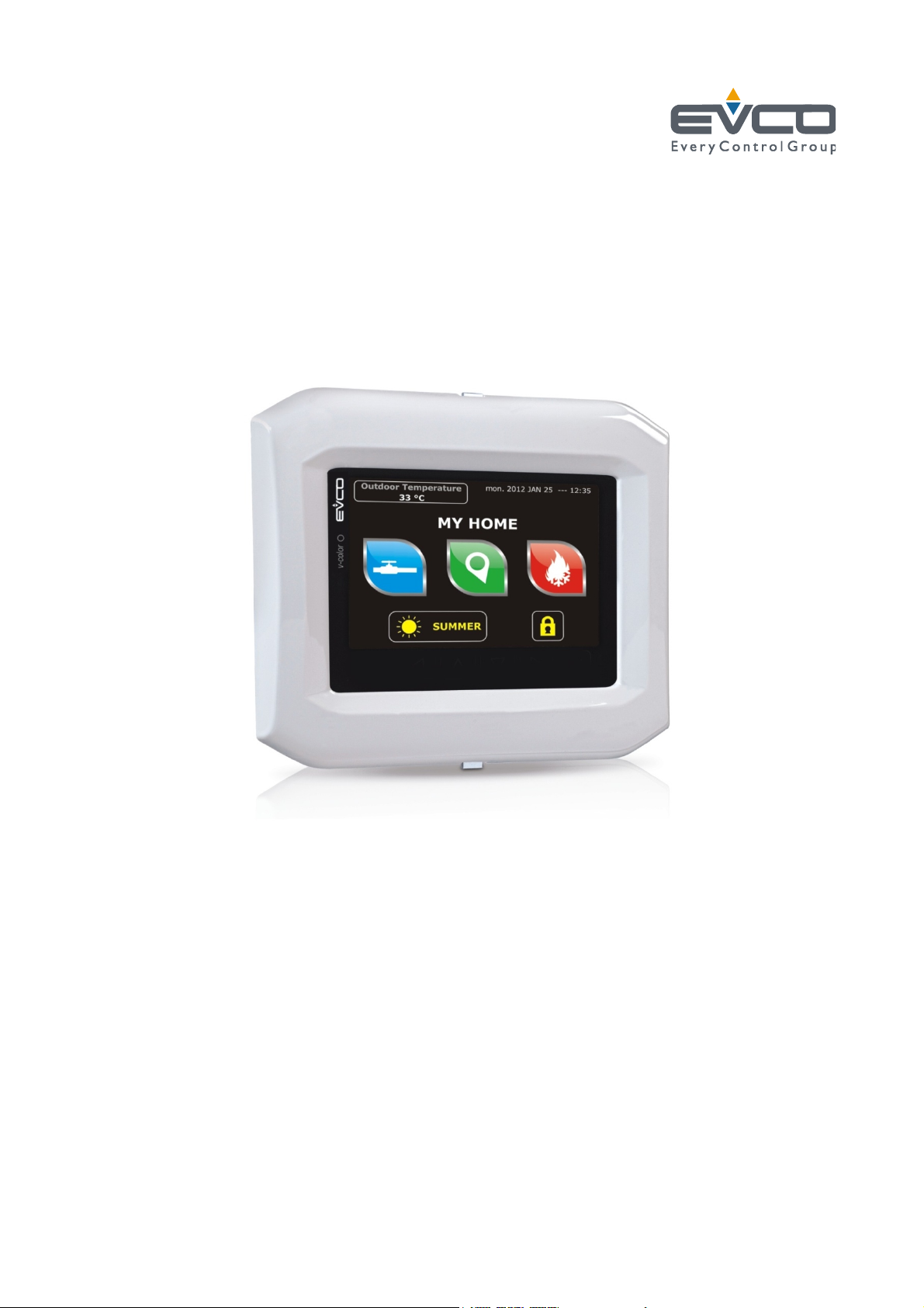
Vcolor
Programmable remote user interfaces, with
color touch-screen TFT graphic display
Hardware manual | ENGLISH
Code 144VCOE104
page 1 of 38
Page 2

EVCO S.p.A. Vcolor | Hardware manual ver. 1.0 | Code 144VCOE104
Important
Read this document thoroughly before installation and before
use of the device and follow all recommendations; keep this
document with the device for future consultation.
Only use the device in the way described in th is docu ment; do
not use the same as a safety device.
Disposal
The device must be disposed of in compliance with local
Standards regarding the collection of electric and electronic
equipment.
page 2 of 38
Page 3

EVCO S.p.A. Vcolor | Hardware manual ver. 1.0 | Code 144VCOE104
Index
1 INTRODUCTION .............................................. 4
1.1 Introduction ................................................... 4
1.2 Summary table of the available models, the main
features and the purchase codes ....................... 5
2 SIZE AND INSTALLATION ................................. 6
2.1 Size ............................................................... 6
2.2 Panel mounting ............................................... 6
2.3 Built-in mounting ............................................ 7
2.4 Wall mounting ................................................ 8
2.5 Additional information for installation ................. 8
3 WIRING DIAGRAM ........................................... 9
3.1 Connectors ..................................................... 9
3.2 Meaning of connectors ..................................... 9
3.3 Plugging-in the line termination of the RS-485
network with MODBUS communication protocol 10
3.4 Plugging-in the line termination of the CAN
network with CANBUS communication protocol . 11
3.5 Polarizing the RS-485 network with MODBUS
communication protocol ................................. 11
3.6 Example of wiring diagram ............................. 12
3.7 Additional information for wiring diagram ......... 13
4 DESCRITPION ............................................... 14
4.1 Description of the front .................................. 14
4.2 Description of the back .................................. 15
5 FIRST USE .................................................... 16
5.1 First use ....................................................... 16
6 PRELIMINARY INFORMATION .......................... 17
6.1 Switching on/off the device ............................ 17
6.2 Access to the menu “Info”, “Diagnostic” and
“Debug” ....................................................... 17
7 CONFIGURATION .......................................... 18
7.1 Setting the date and the time ......................... 18
7.2 Setting the language for showing (if foreseen) the
words of the application project ...................... 19
7.3 Setting the configuration parameters of the menu
“Parameters” ................................................ 19
7.4 Setting the configuration parameters of the menu
“Networks” ................................................... 20
7.5 Uploading and down loading the configuration
parameters................................................... 21
7.6 Configuring an element of a CAN network with
CANBUS communication protocol .................... 24
7.7 List of the configuration parameters ................ 25
8 SIGNALS ...................................................... 31
8.1 Signals ........................................................ 31
9 ACCESSORIES .............................................. 32
9.1 Connecting cables 0810500018/0810500020 .... 32
9.2 Frontal plates CPVP ....................................... 32
9.3 Wall mounting support CPVW00 ...................... 32
9.4 Gasket 0027000007 ...................................... 33
10 TECHNICAL DATA .......................................... 34
10.1 Technical data .............................................. 34
page 3 of 38
Page 4

EVCO S.p.A. Vcolor | Hardware manual ver. 1.0 | Code 144VCOE104
1 INTRODUCTION
1.1 Introduction
Vcolor is a range of programmable remote user interfaces.
Through the interfaces it is possible to manage the
programmable controllers belonging to the c-pro 3 range also
at a distance, in particular the blind versions.
The user interface consists of a color touch-screen TFT graphic
display, it can be developed through the UNI-PRO 3
development environment and guarantees an IP40 protection
rating (IP65 in case of panel mounting with gasket
0027000007, to order separately), for easy cleaning.
They can work both as browser of programmable controllers
(browsers) and in commander mode, getting the controllers
(slaves) to serve the commands coming from the interface.
The interfaces can easily be integrated both in residentia l and
in commercial environments; at their front it is possible to
apply the frontal plates CPVP EVCO (to order separately) or
the plates belonging to the series "Living" and to the series
"Light" BTicino.
Installation is by panel, built-in (in box like “506e” BTicino) or
by wall (in wall mounting support CPVW00 EVCO, to order
separately).
page 4 of 38
Page 5

EVCO S.p.A. Vcolor | Hardware manual ver. 1.0 | Code 144VCOE104
1.2 Summary table of the available models, the main features and the purchase
codes
The following table shows the available models.
Available models: EPV4CBR
The following table shows the main features of the devices.
User interface EPV4CBR
118.0 x 111.0 mm (4.645 x 4.370
in; L x H)
320 x 240 pixel color touch-screen
TFT graphic display
protection rating IP40 (IP65 in case of panel mounting with gasket 0027000007, to order separately)
Connections: EPV4CBR
screw removable terminal blocks •
Power supply: EPV4CBR
24 VAC/DC not isolated •
Communication ports: EPV4CBR
RS-485 MODBUS •
CAN CANBUS •
•
•
USB •
Other features: EPV4CBR
real time clock •
alarm and signalling buzzer •
For further information look at chapter 10 “TECHNICAL DATA”.
The following table shows the purchase codes.
Purchase codes: EPV4CBR
For further information contact the EVCO sales network.
page 5 of 38
Page 6

EVCO S.p.A. Vcolor | Hardware manual ver. 1.0 | Code 144VCOE104
2 SIZE AND INSTALLATION
2.1 Size
The following drawing shows the size of the devices; size is in mm (in).
The following table shows the size of the panel cut-out in case of panel mounting; size is in mm (in).
Size Minimum Typical Maximum
A 104.0 (4.094) 104.0 (4.094) 104.8 (4.125)
B 70.0 (2.755) 70.0 (2.755) 70.8 (2.787)
C 22.0 (0.866) 23.0 (0.905) 24.0 (0.944)
D 40.8 (1.606) 41.8 (1.645) 42.8 (1.685)
2.2 Panel mounting
The following drawing shows the installation of the devices.
Through the gasket 0027000007 (to order separately) it is possible to guarantee a protection rating IP65; through the frontal plates
CPVP EVCO (to order separately) or the plates belonging to the series "Living" and to the series "Light" BTicino it is possible to integrate
the devices both in residential and commercial environments.
page 6 of 38
Page 7

EVCO S.p.A. Vcolor | Hardware manual ver. 1.0 | Code 144VCOE104
2.3 Built-in mounting
The following drawing shows the built-in mounting of the devices (in box like “506e” BTicino).
It is necessary to insta ll the box vertically.
Through the frontal plates CPVP EVCO (to order separately) or the plates belonging to the series "Living" and to the series "Light"
BTicino it is possible to integrate the devices both in residential and commercial environments.
page 7 of 38
Page 8

EVCO S.p.A. Vcolor | Hardware manual ver. 1.0 | Code 144VCOE104
2.4 Wall mounting
The following drawing shows the wall mounting of the devices (in wall mounting support CPVW00 EVCO, to order separately).
Through the frontal plates CPVP EVCO (to order separately) or the plates belonging to the series "Living" and to the series "Light"
BTicino it is possible to integrate the devices both in residential and commercial environments.
2.5 Additional information for installation
- make sure the working conditions of the device (operating temperature, operating humidity, etc.) are in the limits
indicated; look at chapter 10 “TECHNICAL DATA”.
- do not install the device close to heating sources (heaters, hot air ducts, etc.), devices having big magnetos (big speakers,
etc.), locations subject to direct sunlight, rain, humidity, dust, mechanical vibrations or bumps
- according to the safety legislation, the protection against possible contacts with the electrical parts must be ensured by a
correct installation of the device; all the parts which ensure the protection must be fixed so that you can not remove them
if not by using a tool.
page 8 of 38
Page 9

EVCO S.p.A. Vcolor | Hardware manual ver. 1.0 | Code 144VCOE104
3 WIRING DIAGRAM
3.1 Connectors
The following drawing shows the connectors of the devices.
3.2 Meaning of connectors
The following tables show the meaning of the connectors of the devices.
CANBUS CAN port
CAN port with CANBUS communication protocol.
Terminal Meaning
1 ground (gnd)
2 negative pole (-)
3 positive pole (+)
The CANBUS CAN port is the port to communicate with the programmable controllers and the I/O expansions belonging to the c-pro 3
range.
Power supply
Power supply device (24 VAC/DC not isolated).
If the device is powered in direct current, it will be necessary to respect the polarity of the power supply voltage.
Terminal Meaning
4 negative pole (-)
5 positive pole (+)
MODBUS RS-485 port
RS-485 port with MODBUS communication protocol.
If the device works in browser modality, the communication protocol will be slave; if the device works in commander modality, the
communication protocol can be MODBUS master or MODBUS slave (this feature can be selected through the development environment
UNI-PRO 3).
Also consult the manual Modbus specifications and implementation guides available on the web site www.modbus.org.
Terminal Meaning
6 negative pole (B / -)
7 positive pole (A / +)
page 9 of 38
Page 10

EVCO S.p.A. Vcolor | Hardware manual ver. 1.0 | Code 144VCOE104
The following table shows the Function codes supported by the device, on condition that it works in commander modality and the
communication protocol is MODBUS.
Function code Meaning
FC 01 read coils
FC 02 read discrete inputs
FC 03 read multiple registers
FC 05 write single coil
FC 06 write single register
FC 08 diagnostic
FC 15 write multiple coils
FC 16 write multiple registers
FC 23 read write multiple registers (maximum 10 registers)
Through the MODBUS RS-485 port it is possible to make one of the following operations:
- configuring the device (through the Parameters Manager software set-up system)
- supervisioning the device (through the CloudEvolution plant monitoring and supervision system, via Web
- use of the MODBUS master functionality with other devices.
USB port
Through the USB port it is possible to make one of the following operations:
- upload and download the application software (through the development environment UNI-PRO 3 or through a USB flash
drive)
- debugging the software (through the development environment UNI-PRO 3 and on condition the device works in
commander modality)
- configuring the device (through the Parameters Manager software set-up system or through a USB flash drive)
- moving files (the development environment UNI-PRO 3)
- data logging (through a USB flash drive and on condition the device works in commander modality).
3.3 Plugging-in the line termination of the RS-485 network with MODBUS
communication protocol
To reduce the reflections on the signal transmitted along the cables connecting the devices to a RS-485 network with MODBUS
communication protocol it is necessary to plug-in the line termination of the first and of the last element of the network.
To plug-in the line termination, position micro switch 1 on position ON.
The micro switch is located at the back of the devices.
page 10 of 38
Page 11

EVCO S.p.A. Vcolor | Hardware manual ver. 1.0 | Code 144VCOE104
3.4 Plugging-in the line termination of the CAN network with CANBUS
communication protocol
To reduce the reflections on the signal transmitted along the cables connecting the devices to a CAN network with CANBUS
communication protocol it is necessary to plug-in the line termination of the first and of the last element of the network.
To plug-in the line termination, position micro switch 2 on position ON.
The micro switch is located at the back of the devices.
3.5 Polarizing the RS-485 network with MODBUS communication protocol
The devices are not able to polarize a RS-485 network with MOSBUS communication protocol; it is necessary the network is polarized
by another element.
page 11 of 38
Page 12

EVCO S.p.A. Vcolor | Hardware manual ver. 1.0 | Code 144VCOE104
3.6 Example of wiring diagram
The following drawing shows an example of wiring diagram of the devices.
page 12 of 38
Page 13

EVCO S.p.A. Vcolor | Hardware manual ver. 1.0 | Code 144VCOE104
3.7 Additional information for wiring diagram
- do not operate on the terminal blocks with electrical or pneumatic screwers
- if the device has been moved from a cold location to a warm one, the humidity could condense on the inside; wait about an
hour before powering it
- test the working power supply voltage, working electrical frequency and working electrical power of the device; they must
correspond with the local power supply; look at chapter 10 “TECHNICAL DATA”.
- disconnect the local power supply before servicing the device
- connect the device to a RS-485 network with MODBUS communication protocol using a twisted pair
- connect the device to a CAN network with CANBUS communication protocol using a twisted pair
- connect the power cables the most possible away from the signal’s ones
- for repairs and information on the device please contact the EVCO’s sales network.
page 13 of 38
Page 14

EVCO S.p.A. Vcolor | Hardware manual ver. 1.0 | Code 144VCOE104
4 DESCRITPION
4.1 Description of the front
The following drawing shows the aspect of the front of the devices.
The following table shows the meaning of the parts of the front of the devices.
PART MEANING
1 area “HOME”
2 area “ESCAPE”
3 area “LEFT”
4 area “UP”
5 area “DOWN”
6 area “RIGHT”
7 area “ENTER”
8 area “USER”
9 display
For further information look at the following chapters.
page 14 of 38
Page 15

EVCO S.p.A. Vcolor | Hardware manual ver. 1.0 | Code 144VCOE104
4.2 Description of the back
The following drawing shows the aspect of the back of the devices
The following table shows the meaning of the parts of the back of the devices.
PART MEANING
1 RS-485 communication port
dip switch to:
2
- plug in the line termination of the RS-485 network with MODBUS communication protocol
- plug in the line termination of the CAN network with CANBUS communication protocol
3 CAN communication port
4 power supply
5 signal LED
6 USB communication port
For further information look at the following chapters.
page 15 of 38
Page 16

EVCO S.p.A. Vcolor | Hardware manual ver. 1.0 | Code 144VCOE104
5 FIRST USE
5.1 First use
Operate as follows:
1. Make the installation of the device with the modality shown in chapter 2 “SIZE AND INSTALLATION” following all the
additional informat ion re lated in paragraph 3.7 “
2. Make the wiring diagram of the device as shown in chapter 3 “WIRING DIAGRAM” following all the additional information
related in paragraph 3.7 “Additional information for wir ing diagram” without wiring the power supply.
3. Connect the power supply of the device: it will be started an internal test.
The test takes typically some seconds.
4. To the end of the internal test the display shows Checking . . .
5. Press and release the area in the bottom right-hand corner of the display: the display will show the sensitive areas.
6. Set the date and the time; look at paragraph 7.1 “Setting the date and the time”.
7. Configure the device with the procedure shown in paragraph 7.4 “Setting the configuration parameters of the menu
“Networks””.
The following table shows the meaning of the main configuration parameters; the parameters are listed with the order it is
opportune the device is configured.
PARAM. MENU MEANING
MyNode Networks / CAN bus local CAN node address, or of the device 99
FACTORY
SETTING
Network
Node
Address Networks / UART
Parity Networks / UART
Baudrate Networks / UART
Networks / CAN bus
remote CAN nodes address, or of the other elements of the
network
device MODBUS address (meaningful on condition that the
communication protocol is MODBUS slave)
parity of the MODBUS communication
none = none
odd = odd
even = even
baud rate of the MODBUS communication
1200 = 1,200 baud
2400 = 2,400 baud
4800 = 4,800 baud
9600 = 9,600 baud
19200 = 19,200 baud
28800 = 28,800 baud
38400 = 38,400 baud
57600 = 57,600 baud
- - -
1
even
9600
number of stop bit of the MODBUS communication
Bit Stop Networks / UART
According to the factory setting the device works in browser modality.
For further information look at the following paragraphs.
1 bit = 1 bit
2 bit = 2 bit
page 16 of 38
1 bit
Page 17

EVCO S.p.A. Vcolor | Hardware manual ver. 1.0 | Code 144VCOE104
6 PRELIMINARY INFORMATION
6.1 Switching on/off the device
To switch on the device, operate as follows:
1. Connect the power supply: i twill be started an
internal test.
The test takes typically a few seconds.
2. To the end of the internal test press and release
the area in the bottom right-hand corner of the
display: the display will show the sensitive areas.
To switch off the device, operate as follows:
3. Switch off the power supply.
6.2 Access to the menu “Info”,
“Diagnostic” and “Debug”
To gain access to the menu “Info”, “Diagnostic” and “Debug”,
operate as follows:
1. Switch on the device and show the sensitive
areas; look at paragraph 6.1 “Switching on/off the
device”.
2. Press and release the area “USER”: the display will
show the menu “Network Status(CAN)”.
3. Press and release the area “ENTER”: the display
will show the menu “V-COLOR PROG”.
4. Press and release the area “DOWN” to select the
menu (for example to select the menu
“Diagnostic”).
5. Press and release the area “ENTER”.
To quit the procedure, operate as follows:
6. Press and release over and over again the area
“ESCAPE”.
Showing the sensitive areas
Selecting the menu “Diagnostic”
page 17 of 38
Page 18

EVCO S.p.A. Vcolor | Hardware manual ver. 1.0 | Code 144VCOE104
7 CONFIGURATION
7.1 Setting the date and the time
According to the factory settings the date is shown in the
format dd mm yy and the time in the format 24 h.
Through the parameters Year format and Time AM/PM it is
possible to set respectively another year format and time
format.
To set the date and the time, operate as follows:
1. Switch on the device and show the sensitive
areas; look at paragraph 6.1 “Switching on/off the
device”.
2. Press and release the area “USER”: the display will
show the menu “Network Status (CAN)”.
3. Press and release the area “ENTER”: the display
will show the menu “V-COLOR PROG”.
4. Press and release the area “DOWN” to select the
date and the time.
5. Press and release the area “ENTER”.
6. Press and release the area “UP” or the area
“DOWN” to set the value of the field.
7. Press and release the area “LEFT” or the area
“RIGHT” (possible modifications will be saved) to
set the value of the following or previous field.
8. Repeat steps 6... 7.
To quit the procedure, operate as follows:
9. Press and release over and over again the area
“ESCAPE”.
Selecting the date and the time
page 18 of 38
Page 19

EVCO S.p.A. Vcolor | Hardware manual ver. 1.0 | Code 144VCOE104
7.2 Setting the language for
showing (if foreseen) the
words of the application project
To set the language for showing (if foreseen) the words of the
application project, operate as follows:
1. Switch on the device and show the sensitive
areas; look at paragraph 6.1 “Switching on/off the
device”.
2. Press and release the area “USER”: the display will
show the menu “Network Status(CAN)”.
3. Press and release the area “ENTER”: the display
will show the menu “V-COLOR PROG”.
4. Press and release the area “DOWN” to select the
menu “Languages”.
If the device works in browser modality, the menu
“Languuages” will not be accessible.
5. Press and release the area “ENTER”.
6. Press and release “UP” or the area “DOWN” to set
the value of the field.
7. Press and release the area “ENTER”: the device
will quit the procedure.
7.3 Setting the configuration
parameters of the menu
“Parameters”
To gain access to the procedure, operate as follows:
1. Switch on the device and show the sensitive
areas; look at paragraph 6.1 “Switching on/off the
device”.
2. Press and release the area “USER”: the display will
show the menu “Network Status(CAN)”.
3. Press and release the area “ENTER”: the display
will show the menu “V-COLOR PROG”.
4. Press and release the area “DOWN” to select the
menu “Parameters”.
5. Press and release the area “ENTER”: the display
will show the window “Input Password”.
6. Press and release again the area “ENTER”.
7. Press and release the area “DOWN” to set “-19”.
8. Press and release the area “ENTER”: the device
will show the menu “Parameters”.
To select a parameter, operate as follows:
9. Press and release the area “UP” or the area
“DOWN”.
To set a parameter, operate as follows:
10. Press and release the area “ENTER”.
11. Press and release the area “UP” or the area
“DOWN” to set the value of the parameter.
12. Press and release the area “ENTER”.
Selecting the menu “Languages”
Selecting the menu “Parameters”
Access to the menu “Parameters”
page 19 of 38
Page 20

EVCO S.p.A. Vcolor | Hardware manual ver. 1.0 | Code 144VCOE104
To quit the procedure, operate as follows:
13. Press and release over and over again the area
“ESCAPE”.
Switch off/on the power supply of the device after the
parameters setting.
7.4 Setting the configuration
parameters of the menu
“Networks”
To gain access to the procedure, operate as follows:
1. Switch on the device and show the sensitive
areas; look at paragraph 6.1 “Switching on/off the
device”.
2. Press and release the area “USER”: the display will
show the menu “Network Status(CAN)”.
3. Press and release the area “ENTER”: the display
will show the menu “V-COLOR PROG”.
4. Press and release the area “DOWN” to select the
menu “Networks”.
5. Press and release the area “ENTER”: the display
will show the submenu of the menu “Networks”.
6. Press and release the area “DOWN” to select the
submenu (for example to select the submenu
“UART”).
7. Press and release the area “ENTER”: the display
will show the window “Input Password”.
8. Press and release again the area “ENTER”.
9. Press and release the area “DOWN” to set “-19”.
10. Press and release the area “ENTER”: the device
will show the selected submenu.
To select a parameter, operate as follows:
11. Press and release the area “UP” or the area
“DOWN”.
To set a parameter, operate as follows:
12. Press and release the area “ENTER”.
13. Press and release the area “UP” or the area
“DOWN” to set the value of the parameter.
14. Press and release the area “ENTER”.
To quit the procedure, operate as follows:
15. Press and release over and over again the area
“ESCAPE”.
Switch off/on the power supply of the device after the
parameters setting.
Selecting the menu “Networks”
Selecting the submenu “UART”
Access to the submenu of the menu “Networks”
page 20 of 38
Page 21

EVCO S.p.A. Vcolor | Hardware manual ver. 1.0 | Code 144VCOE104
7.5 Uploading and downloading the
configuration parameters
7.5.1 Uploading the configuration parameters
The upload of the configuration parameters can be done on
condition that the firmwares coincide.
To make the upload of the configuration parameters, operate
as follows:
1. Switch on the device and show the sensitive
areas; look at paragraph 6.1 “Switching on/off the
device”.
2. Press and release the area “USER”: the display will
show the menu “Network Status(CAN)”.
3. Press and release the area “ENTER”: the display
will show the menu “V-COLOR PROG”.
4. Press and release the area “DOWN” to select the
menu “Backup/Restore”.
If the device works in browser modality, the menu
“Backup/Restore” will not be available.
5. Press and release the area “ENTER”: the display
will show the window “Input Password”.
6. Press and release again the area “ENTER”.
7. Press and release the area “DOWN” to set “-19”.
8. Press and release the area “ENTER”: the display
will show the submenu of the menu
“Backup/Restore”.
9. Press and release the area “DOWN” to select the
submenu (for example the submenu “Backup
Memory”).
Select the submenu “USB Key” to make the upload
from a USB key (in this case it is necessary make
sure to have plugged a USB key in the USB
communication port and containing configuration
parameters belonging to a firmware that
coincides); select the submenu “Backup Memory”
to make the upload of the memory of the device.
10. Press and release the area “ENTER”: the display
will show the submenu of the selected submenu
(for example the submenu of the submenu
“Backup Memory”).
11. Press and release the area “DOWN” to select the
submenu (for example the submenu “Hardware
configuration”).
Select the submenu “Application parameters” to
make the upload of the configuration parameters
of the application software; select the submenu
“Hardware configuration” to make the upload of
the configuration parameters of the device.
12. Press and release the area “ENTER”.
13. Press and release the area “DOWN” to select
“Restore from USB” or “Restore from
memory” (according to the option selected in step
9).
Selecting the menu “Backup/Restore”
Selecting the submenu “Backup Memory”
Selecting the submenu “Hardware configuration”
page 21 of 38
Page 22

EVCO S.p.A. Vcolor | Hardware manual ver. 1.0 | Code 144VCOE104
14. Press and release the area “ENTER”: it will be
started the upload of the configuration
parameters.
The upload takes typically a few seconds; if the
operation is not completed succesfully, the display
will show an error indication (for example “Status:
Read Error”).
To quit the procedure, operate as follows:
15. Press and release over and over again the area
“ESCAPE”.
7.5.2 Downloading the configuration parameters
To make the download of the configuration parameters,
operate as follows:
1. Switch on the device and show the sensitive
areas; look at paragraph 6.1 “Switching on/off the
device”.
2. Press and release the area “USER”: the display will
show the menu “Network Status(CAN)”.
3. Press and release the area “ENTER”: the display
will show the menu “V-COLOR PROG”.
4. Press and release the area “DOWN” to select the
menu “Backup/Restore”.
If the device works in browser modality, the menu
“Backup/Restore” will not be available.
5. Press and release the area “ENTER”: the display
will show the window “Input Password”.
6. Press and release again the area “ENTER”.
7. Press and release the area “DOWN” to set “-19”.
8. Press and release the area “ENTER”: the display
will show the submenu of the menu
“Backup/Restore”.
9. Press and release the area “DOWN” to select the
submenu (for example the submenu “Backup
Memory”).
Select the submenu “USB Key” to make the
download into a USB key (in this case it is
necessary make sure to have plugged a USB key
in the USB communication port); select the
submenu “Backup Memory” to make the download
of the memory of the device.
10. Press and release the area “ENTER”: the display
will show the submenu of the selected submenu
(for example the submenu of the submenu
“Backup Memory”).
11. Press and release the area “DOWN” to select the
submenu (for example the submenu “Hardware
configuration”).
Select the submenu “Application parameters” to
make the download of the configuration
parameters of the application software; select the
submenu “Hardware configuration” to make the
download of the configuration parameters of the
device.
12. Press and release the area “ENTER”.
Selecting the menu “Backup/Restore”
Selecting the submenu “Backup Memory”
Selecting the submenu “Hardware configuration”
page 22 of 38
Page 23

EVCO S.p.A. Vcolor | Hardware manual ver. 1.0 | Code 144VCOE104
13. Press and release the area “DOWN” to select
“Save on USB” or “Save on memory” (according
to the option selected in step 9).
14. Press and release the area “ENTER”: it will be
started the download of the configuration
parameters.
The download takes typically a few seconds; if the
operation is not completed succesfully, the display
will show an error indication (for example “Status:
Read Error”).
To quit the procedure, operate as follows:
15. Press and release over and over again the area
“ESCAPE”.
page 23 of 38
Page 24

EVCO S.p.A. Vcolor | Hardware manual ver. 1.0 | Code 144VCOE104
7.6 Configuring an element of a
CAN network with CANBUS
communication protocol
To configure an element of a CAN network with CANBUS
communication protocol, operate as follows:
1. Disconnect the power supply of the device and of
the other element of the network.
2. Connect the device to the other element of the
network through the CAN communication port;
look at chapter 3 “WIRING DIAGRAM”.
3. Connect the power supply of the device and of the
other element of the network.
4. Set the configuration parameter Network Node
with the procedure shown in paragraph 7.4
“Setting the configuration parameters of the menu
“Networks””.
According to the factory settings the CAN address
of a controller is 1 (in this case it is necessary to
set parameter Network Node to [1] 1) and the
CAN address of an I/O expansion is 2 (in this case
it is necessary to set the parameter Network Node
to [2] 2).
5. Press and release over and over again the area
“ESCAPE” as long as the display shows the menu
“Network Status(CAN)”.
6. Press and release the area “DOWN” to select the
element of the network.
7. Press and release the area “ENTER”: the display
will show the main menu of the element of the
network.
8. Configure the element of the network with the
procedures shown in chapter 7
“CONFIGURATION”.
Switch off/on the power supply of the element of the
network after the configuration.
Showing the menu “Network Status(CAN)”
page 24 of 38
Page 25

EVCO S.p.A. Vcolor | Hardware manual ver. 1.0 | Code 144VCOE104
7.7 List of the configuration parameters
7.7.1 Configuration parameters of the menu “Info”
The following table shows the meaning of the configuration parameters of the menu “Info”.
PARAM. MIN. MAX. U.M. DEF. DESCRIPTION
PROJ parameter available in read only mode information on the application project (project, version and revision)
FW parameter available in read only mode
HW parameter available in read only mode
SW parameter available in read only mode
SN parameter available in read only mode
DATE parameter available in read only mode date and time of the last compiling of the application project
7.7.2 Configuration parameters of the menu “Languages”
The following table shows the meaning of the configuration parameters of the menu “Languages”.
PARAM. MIN. MAX. U.M. DEF. DESCRIPTION
English parameter available in read only mode
information on the firmware (code, version, revision and under
revison)
information on the hardware (version, revision, generic (G) or
special (S))
information on the development environment UNI-PRO 3 (version
and revision)
informazioni relative al serial number e all’esito del collaudo
produttivo
showing the words of the application software in English (if
foreseen)
Italiano parameter available in read on ly mode
Français parameter available in read only mode
Español parameter available in read only mode
Deutsch parameter available in read only mode
Russian parameter available in read only mode
Português parameter available in read only mode
showing the words of the application software in Italian (if
foreseen)
showing the words of the application software in French (if
foreseen)
showing the words of the application software in Spanish (if
foreseen)
showing the words of the application software in German (if
foreseen)
showing the words of the application software in Russian (if
foreseen)
showing the words of the application software in Portoguese (if
foreseen)
page 25 of 38
Page 26

EVCO S.p.A. Vcolor | Hardware manual ver. 1.0 | Code 144VCOE104
7.7.3 Configuration parameters of the menu “Parameters”
The following table shows the meaning of the configuration parameters of the menu “Parameters”.
PARAM. MIN. MAX. U.M. DEF. DESCRIPTION
Date Char
Separator
- - - - - - - - - - - - ASCII character date separator
Year format - - - - - - - - - YY
Date format - - - - - - - - - dd mm yy
Time Char
Separator
Time With
Sec
- - - - - - - - - : ASCII character time separator
- - - - - - - - - YES
Time AM/PM - - - - - - - - - NO
year format
YY = two numbers (for example 13)
YYYY = four numbers (for example 2013)
date format
yy mm dd = year, month and day
mm dd yy = month, day and year
dd mm yy = day, month and year
showing the seconds in the time
YES = yes
time format
NO = 24 h (for example 15:20)
YES = 12 h (for example 3:20 PM)
Backlight
Mode
Backlight
Timeout
- - - - - - - - - TIME
0 240 s 60
I/O Timeout 0 240 s 60
Print
Loading
Password
Timeout
- - - - - - - - - NO
0 240 s 60
kind of back light
OFF = the back light will always be off
ON = the back light will always be on
TIME = the back light will be on the time you have set
with parameter Backlight Timeout from the last
operation
backlight duration (meaningful if parameter Backlight Mode has
value Time)
time-out of the local CAN communication, or of the device (once
the time you have set with this parameter has elapsed without
CAN communication, the remote I/O coming from the controllers
will be disabled)
showing the indication Loading . . . when loa ding a page of the
application project
YES = yes
time-out of the access password for menu “Parameters”,
“Networks” and “Backup/Restore” (once the time you have set
with this parameter has elapsed from the last operation after the
menu has been accessed, to gain access to it again it is necessary
to set the password again)
page 26 of 38
Page 27

EVCO S.p.A. Vcolor | Hardware manual ver. 1.0 | Code 144VCOE104
kind of beep when pressing a sensitive area of the display of the
device
Beep Mode 0 2 - - - 2
0 = no beep
1 = always
2 = on condition the area is sensitive
Print Frame 0 1 - - - 0
showing frames instead small size pages
1 = yes
7.7.4 Configuration parameters of the submenu “CAN bus” of the menu “Networks”
The following table shows the meaning of the configuration parameters of the section “CAN Network” of the submenu “CAN bus” of the
menu “Networks”.
PARAM. MIN. MAX. U.M. DEF. DESCRIPTION
MyNode 1 127 - - - 99 local CAN node address, or of the device
Master - - - - - - - - - YES the device always works as master
baud rate of the CAN communication
20K = 20,000 baud
50K = 50,000 baud
125K = 125,000 baud
Baud - - - - - - - - - Auto
500K = 500,000 baud
Auto = the device automatically detects the baud rate of
the other elements of the networ, on condition
that it is one of those listed here above; on
afterwards set the baud rate to the same value of
the other elements
Timeout 1 240 s 5
Network
Node
[1] 1 [32] 127 - - - - - -
time-out of the remote CAN communication, or with the other
elements of the network (once the time you have set with this
parameter has elapsed without CAN communication with an
element, this is disabled)
remote CAN nodes address, or of the other elements of the
network (example for [1] 2)
[1] = node
2 = node address
page 27 of 38
Page 28

EVCO S.p.A. Vcolor | Hardware manual ver. 1.0 | Code 144VCOE104
Press and release key “RIGHT” to show the section “CAN Status” of the submenu “CAN bus” of the menu “Networks” .
PARAM. MIN. MAX. U.M. DEF. DESCRIPTION
Cnt Rx parameter available in read only mode reserved
Cnt Tx parameter available in read only mode reserved
Cnt Ovf parameter available in read only mode reserved
Cnt Passive parameter available in read only mode reserved
Cnt Bus Off parameter available in read only mode reserved
BufRx Valid parameter available in read only mode reserved
BufTx Valid parameter available in read only mode reserved
Cnt Tx Err parameter available in read only mode reserved
Cnt Rx Err parameter available in read only mode reserved
Cnt Stuff parameter available in read only mode reserved
Cnt Form parameter available in read only mode reserved
Cnt Ack parameter available in read only mode reserved
Cnt Bit1 parameter available in read only mode reserved
Cnt Bit0 parameter available in read only mode reserved
Cnt CRC parameter available in read only mode reserved
Press and release again key “RIGHT” to show the section “CAN Bit Timing” of the submenu “CAN bus” of the menu “Networks” .
PARAM. MIN. MAX. U.M. DEF. DESCRIPTION
BRP parameter available in read only mode reserved
SJW parameter available in read only mode reserved
T.SEG1 parameter available in read only mode reserved
T.SEG2 parameter available in read only mode reserved
page 28 of 38
Page 29

EVCO S.p.A. Vcolor | Hardware manual ver. 1.0 | Code 144VCOE104
7.7.5 Configuration parameters of the submenu “UART” of the menu “Networks”
The following table shows the meaning of the configuration parameters of the submenu “UART” of the menu “Networks”.
PARAM. MIN. MAX. U.M. DEF. DESCRIPTION
Address 1 247 - - - 1
Parity - - - - - - - - - even
Baudrate - - - - - - - - - 9600
Bit Stop - - - - - - - - - 1 bit
MODBUS address of the device (meaningful if the communication
protocol is MODBUS slave)
parity of the MODBUS communication
none = none
odd = odd
even = even
baud rate of the MODBUS communication
1200 = 1,200 baud
2400 = 2,400 baud
4800 = 4,800 baud
9600 = 9,600 baud
19200 = 19,200 baud
28800 = 28,800 baud
38400 = 38,400 baud
57600 = 57,600 baud
number of stop bit of the MODBUS communication
1 bit = 1 bit
2 bit = 2 bit
time-out of the local MODBUS communication, or of the device
(once the time you have set with this parameter has elapsed from
Timeout 2 240 s 10
the transmission of a request without answer, the transmission of
the request is considered failed and the following request is
transmitted; meaningful if the communication protocol is
MODBUS master)
7.7.6 Configuration parameters of the submenu “USB” of the menu “Networks”
The following table shows the meaning of the configuration parameters of the submenu “USB” of the menu “Networks”.
PARAM. MIN. MAX. U.M. DEF. DESCRIPTION
USB Status
Device
parameter available in read only mode reserved
Device
Status Idle
parameter available in read only mode reserved
Speed
page 29 of 38
Page 30

EVCO S.p.A. Vcolor | Hardware manual ver. 1.0 | Code 144VCOE104
7.7.7 Configuration parameters of the menu “Diagnostics”
The following table shows the meaning of the configuration parameters of the menu “Diagnostics”.
PARAM. MIN. MAX. U.M. DEF. DESCRIPTION
status of the non volatile memory
EEPROM parameter available in read only mode
OK = not in error
ERR = in error
status of the real time clock
OK = not in error
RTC parameter available in read only mode
ERR = in error
LOW = loss of data
DISAB = disabled
status of the stack
STACK parameter available in read only mode
OK = not in error
ERR = in error (for overfow)
status of the math
MATH parameter available in read only mode
OK = not in error
ERR = in error (for overfow, for under flow, for division
by zero or for NaN)
result of the upload and the downloa d of the application software
parameters or of the configuration parameters through the USB
KEY PAR parameter available in read only mode
key
OK = operation completed succesfully
ERR = operation not completed succesfully
7.7.8 Configuration parameters of the menu “Debug”
The following table shows the meaning of the configuration parameters of the menu “Debug”.
PARAM. MIN. MAX. U.M. DEF. DESCRIPTION
Main time parameter available in read only mode main cycle time of the application soft ware (in ms)
max time
main
free stack
main
parameter available in read only mode
parameter available in read only mode minimum main free stack
maximum value of the main cycle time of the application software
(in ms)
100ms time parameter available in read only mode reserved
max time
100 ms
parameter available in read only mode reserved
free stack
100 ms
parameter available in read only mode reserved
page 30 of 38
Page 31

EVCO S.p.A. Vcolor | Hardware manual ver. 1.0 | Code 144VCOE104
8 SIGNALS
8.1 Signals
The following tables shows the meaning of the LED of the device.
LED colour Meaning
green
green
red
red
red
LED power supply device
if it is lit, the device will be powered
LED run
if it is lit, the application software will be compiled and running in release modality
if it flashes slowly, the application software will be compiled and running in debug modality
LED error
if it is lit, an error will be arisen
LED CAN transmission
if it is lit, the device will be configured to communicate via CANBUS with another device but
the CAN communication will not have been set up
if it flashes slowly, the CANBUS communication will have been set up but it will not be
completely correct
if it flashes quickly, the CANBUS communication will have been set up and will be correct
if it is out, no CANBUS communication will be running
LED CAN reception
if it is lit, the device will be configured to communicate via CANBUS with another device but
the CAN communication will not have been set up
if it flashes slowly, the CANBUS communication will have been set up but it will not be
completely correct
if it flashes quickly, the CANBUS communication will have been set up and will be correct
if it is out, no CANBUS communication will be running
The LED are located at the back of the devices; look at paragraph 4.2 “Description of the back”.
page 31 of 38
Page 32

EVCO S.p.A. Vcolor | Hardware manual ver. 1.0 | Code 144VCOE104
9 ACCESSORIES
9.1 Connecting cables 0810500018/0810500020
9.1.1 Preliminary information
Through the cables it is possible to make more accessible the USB port of the devices.
The cable 0810500018 is 2.0 m long; the cable 0810500020 is 0.5 m long.
9.2 Frontal plates CPVP
9.2.1 Preliminary information
Through the plates it is possible to integrate the devices both in residential and commercial environments.
The following table shows the available models.
Colour Code
white CPVP00
black CPVP01
9.3 Wall mounting support CPVW00
9.3.1 Preliminary information
Through the support it is possible to install the devices by wall, reducing the installing operation to a minimum.
page 32 of 38
Page 33

EVCO S.p.A. Vcolor | Hardware manual ver. 1.0 | Code 144VCOE104
9.4 Gasket 0027000007
9.4.1 Preliminary information
Through the gasket it is possible to guarantee an IP65 protection rating in case of panel mounting.
page 33 of 38
Page 34

EVCO S.p.A. Vcolor | Hardware manual ver. 1.0 | Code 144VCOE104
10 TECHNICAL DATA
10.1 Technical data
Purpose of control: operating control device.
Construction of control: electronic device to be incorporated.
Box: self-extinguishing transparent.
Size: 118.0 x 111.0 x 26.7 mm (4.645 x 4.370 x 1.051 in; L x H x P).
- by panel, with self-threading screws
Mounting:
- built-in (in box like “506e” BTicino and self-threading screws)
- by wall (in wall mounting support CPVW00 EVCO, to order separately and with
self-threading screws).
Protection rating: IP40 (IP65 in case of panel mounting with gasket 0027000007, to order separately).
- screw removable terminal blocks (power supply, RS-485 MODBUS port and CAN
CANBUS port)
- USB connector type A (USB port).
The maximum length of the connecting cables are the following:
- power supply: 10 m (32.8 ft)
Connections:
Working temperature: from 0 to 55 °C (from 32 to 131 °F).
Storage temperature: from -10 to 70 °C (from 14 to 158 °F).
- RS-485 MODBUS port: 1,000 m (3,280 ft)
- CAN CANBUS port:
- 1,000 m (3,280 ft) with baud rate 20,000 baud
- 500 m (1,640 ft) with baud rate 50,000 baud
- 250 m (820 ft) with baud rate 125,000 baud
- 50 m (164 ft) with baud rate 500,000 baud.
According to the factory settings, the device automatically detects the baud rate of the other
elements of the network, on condition that it is one of those listed here above; on
afterwards set the baud rate to the same value of the other elements.
Working humidity: from 10 to 90 % of relative humidity without condensate.
Pollution situation: 2.
page 34 of 38
Page 35

EVCO S.p.A. Vcolor | Hardware manual ver. 1.0 | Code 144VCOE104
- 24 VAC (±15%), 50 / 60 Hz (±3 Hz), 3 VA max not isolated
- 24 VDC (-15%, +65%), 2 W max not isolated
supplied by a class 2 circuit.
Protect the power supply by one of the following fuses:
- 160 mA-T if the device is powered in alternating current
Power supply:
- 80 mA-T if the device is powered in direct current.
If the device is powered in direct current, it will be necessary to respect the polarity of the
power supply voltage.
The power supply must galvanically be isolated by those of the other elements of the RS-485
network with MODBUS communication protocol or the CAN network with CANBUS
communication protocol.
Rated impulse voltage: 4 KV.
Overvoltage category: III.
Software class: A.
incorporated (SuperCap).
Real time clock:
Data maintenance in case of absence of the power supply: 24 h with battery full loaded.
Battery loading time: 2 min (the battery is loaded by the power supply of the device).
Type 1 or type 2 actions: Type 1.
Features of actions type 1 or
type 2:
C.
Display: 320 x 240 pixel color resistive touch-screen TFT graphic display.
3 ports:
Communication ports:
- 1 RS-485 port with MODBUS communication protocol
- 1 CAN port with CANBUS communication protocol
- 1 USB port.
Alarm buzzer: incorporated.
page 35 of 38
Page 36

EVCO S.p.A. Vcolor | Hardware manual ver. 1.0 | Code 144VCOE104
page 36 of 38
Page 37

EVCO S.p.A. Vcolor | Hardware manual ver. 1.0 | Code 144VCOE104
Vcolor
Programmable remote user interfaces, with colour touch-
screen TFT graphic display
Hardware manual ver. 1.0
PT - 38/13
Code 144VCOE104
This document belongs to EVCO; EVCO does not take any
responsibility about possible mistakes related.
The customer (OEM, installer or final user) takes all
responsibilities about the configuration of the device.
EVCO does not take any responsibility about damages coming
by the non-observance of additional information.
EVCO reserves the right to make any change without prior
notice and at any time without prejudice the basic safety and
operating features.
page 37 of 38
Page 38

EVCO S.p.A. Vcolor | Hardware manual ver. 1.0 | Code 144VCOE104
EVCO S.p.A.
Via Feltre 81, 32036 Sedico Belluno ITALY
Phone +39/0437/8422 | Fax +39/0437/83648
info@evco.it | www.evco.it
page 38 of 38
 Loading...