

EVCO S.p.A.
c-pro 3 micro CHIL
Programmable controllers for single-and
two-circuits chillers-heat pumps
c-pro 3 micro CHIL | Application manual ver. 1.0 | Codice 144CP3CHE104
Application manual | ENGLISH
Codice 144CP3CHE104
EVCO S.p.A.
c-pro 3 micro CHIL | Application manual ver. 1.0 | Codice 144CP3CHE104
IMPORTANT NOTICE
This Instruction Manual should be read carefully before installation and before use, and all warnings relating
to installation and electrical connections should be observed; the Manual should then be kept for future
reference.
All devices must be disposed of in accordance with local regulations governing the disposal of
electrical and electronic devices.
page 2 of 120

EVCO S.p.A.
SOMMARIO
c-pro 3 micro CHIL | Application manual ver. 1.0 | Codice 144CP3CHE104
1 INTRODUCTION ................................................................................................... 6
1.1 Introduction ..................................................................................................... 6
2 APPLICATIONS .................................................................................................... 7
2.1 Basic application scheme of an Air-To-Water twin circuit chiller ...................... 8
3 HARDWARE SOLUTIONS ...................................................................................... 9
4 DIMENSIONS ..................................................................................................... 10
4.1 Dimensions of controller and user interface ....................................................... 10
4.1.1 Dimensionscontrol modulec-pro 3microCHILand c-pro 3 EXP micro+ ............................................................. 10
5 USER INTERFACE ............................................................................................... 12
5.1 Displays and Keyboards.................................................................................. 12
6 LIST OF PAGES ................................................................................................... 13
6.1 Password ........................................................................................................ 14
6.2 Unit OFF main page ........................................................................................ 14
6.3 Unit ON main page ......................................................................................... 15
6.4 Menu StAt (Only for display LED) ................................................................... 16
6.4.1
Meaning of LED (only for display LED) .................................................................................................. 17
6.5 General Menu ................................................................................................. 18
6.6 User Menu ...................................................................................................... 18
6.7 Maintenance Menu .......................................................................................... 18
6.8 Installer Menu ................................................................................................ 19
6.9 Constructor Menu ........................................................................................... 20
6.10 RTC Menu .................................................................................................... 20
6.11 Alarms Menu ............................................................................................... 20
7 PARAMETERS LIST ............................................................................................. 21
7.1 List of Configuration Parameters .................................................................... 22
7.2 AI Configuration (HA01-HA18 parameters) .................................................... 41
7.3 DI Configuration(HB01-HB18 parameters) ..................................................... 42
7.4 AO Configuration (HC01-HC18 parameters) ................................................... 42
7.5 DO Configuration (HD01-HD18 parameters)................................................... 43
8 REGULATIONS.................................................................................................... 44
8.1 Machine Status ............................................................................................... 44
8.2 Unit Type ........................................................................................................ 45
8.2.1
Water-To-Water Chiller with EVDRIVE03 .............................................................................................. 45
8.2.2
Water-To-Water Chiller ......................................................................................................................... 46
8.2.3
Water-To-Water Chiller+Heat Pump with EVDRIVE03 ........................................................................... 47
8.2.4
Water-To-Water Chiller+Heat Pump ..................................................................................................... 48
8.2.5
Air-To-Water Chiller with EVDRIVE03 ................................................................................................... 49
8.2.6
Air-To-Water Chiller .............................................................................................................................. 50
8.2.7
Air-To-Water Chiller+Heat Pump with EVDRIVE03 ................................................................................ 51
8.2.8
Air-To-Water Chiller+Heat Pump .......................................................................................................... 52
page 3 of 120

EVCO S.p.A.
c-pro 3 micro CHIL | Application manual ver. 1.0 | Codice 144CP3CHE104
8.3 Configuration of Circuits ................................................................................. 53
8.4 Operating Mode Control .................................................................................. 54
8.5 Setting the RTC .............................................................................................. 55
8.6 Compressor Control ........................................................................................ 56
8.6.1
Lateral-band (LB) control ...................................................................................................................... 56
8.6.2
Zero energy band (ZEB) control ............................................................................................................ 57
8.6.3
Auto adaptive control ........................................................................................................................... 58
8.7 Compressor Management ............................................................................... 58
8.7.1
Compressor status ................................................................................................................................ 58
8.7.2
Rotation of compressors ....................................................................................................................... 58
8.7.3
Pump-down switch-OFF procedure ....................................................................................................... 59
8.7.4
Relative-threshold pump-down ............................................................................................................. 59
8.7.5
Protection timings ................................................................................................................................. 60
8.7.6
Thermal protection inputs ..................................................................................................................... 61
8.8 Condenser control .......................................................................................... 61
8.8.1
Modulating fan control .......................................................................................................................... 61
8.8.2
Single stage fan control ........................................................................................................................ 64
8.8.3
Condenser valve control ........................................................................................................................ 64
8.8.4
Single condenser ................................................................................................................................... 64
8.9 Fan Management ............................................................................................ 65
8.9.1
Fan status ............................................................................................................................................. 65
8.9.2
Fan timings ........................................................................................................................................... 65
8.9.3
Thermal Protection Inputs .................................................................................................................... 65
8.10 Circulating Pump Management .................................................................... 66
8.10.1
Pump Status .......................................................................................................................................... 67
8.10.2
Flow Meter Management ....................................................................................................................... 67
8.11 Circulating Source Pump Management ........................................................ 68
8.12 Defrosting Management .............................................................................. 68
8.12.1
Defrosting cycle compensation ............................................................................................................. 69
8.13 Anti-freeze management / Chilling-support heating coils ........................... 69
8.14 Single evaporation ...................................................................................... 69
8.15 Free-Cooling Management........................................................................... 70
8.15.1
Enabling of Free-Cooling ....................................................................................................................... 70
8.15.2
Regulation of Free-Cooling .................................................................................................................... 70
8.15.3
Free-Cooling control valve .................................................................................................................... 72
8.16 Temperature Alarm Control ......................................................................... 73
8.16.1
Low and high temperature alarm management ..................................................................................... 73
8.16.2
Management of primary exchanger efficiency alarm ............................................................................. 73
8.17 Pressure Alarm Control ............................................................................... 73
8.17.1
Management of high-pressure pressure-switch alarm .......................................................................... 73
8.17.2
Management of high-pressure transducer alarm ................................................................................... 73
8.17.3
Management of low-pressure pressure-switch alarm (chiller mode) .................................................... 73
8.17.4
Management of low-pressure transducer alarm (heat pump mode) ...................................................... 74
8.17.5
Low start-up pressure alarm ................................................................................................................. 74
8.18 Time schedule ............................................................................................. 75
8.19 Miscellaneous Management ......................................................................... 76
8.19.1
Set point variation by schedule timer .................................................................................................... 76
8.19.2
Dynamic set point ................................................................................................................................. 76
page 4 of 120

EVCO S.p.A.
8.19.3
8.19.4
8.19.5
8.19.6
8.19.7
8.19.8
Forced shutdown ................................................................................................................................... 77
High-pressure reduction at high temperatures (chiller) ........................................................................ 77
Low-pressure partialization at low temperatures (heat pump) ............................................................. 78
Operating limit management (heat pump) ............................................................................................ 79
Function of Cooling/Heatingupon request ............................................................................................. 79
Set-point change from digital input ....................................................................................................... 79
c-pro 3 micro CHIL | Application manual ver. 1.0 | Codice 144CP3CHE104
8.20 Management of EVDRIVE03 integrated into the system .............................. 80
8.20.1
Enabling of EEV operation ..................................................................................................................... 80
8.20.2
PID parameters set ............................................................................................................................... 80
8.20.3
Modulation of the SH set ....................................................................................................................... 80
8.20.4
CAN Configuration ................................................................................................................................. 80
8.21 Manual operation ........................................................................................ 81
8.21.1
Compressors ......................................................................................................................................... 81
8.21.2
Fans ...................................................................................................................................................... 81
8.21.3
Pumps ................................................................................................................................................... 81
8.22 Resetting of default parameters .................................................................. 82
8.23 Parametering key ........................................................................................ 82
9 WIRING DIAGRAM ............................................................................................. 83
9.1 Connection layout c-pro 3 micro CHIL ................................................................ 83
9.2 Connection layout c-pro 3 EXP micro+ ............................................................... 85
9.3 Connection layout EVDRIVE03 ............................................................................ 87
9.4 Connection layout Vgraph ................................................................................... 89
9.5 c-pro 3 micro CHIL ............................................................................................ 90
10 9.5.1 Table of connection c-pro 3 micro CHIL .................................................... 91
11 DIAGNOSTICS .................................................................................................... 92
11.1 Manual and Automatic Alarms ..................................................................... 92
11.2 Manual-reset alarms ................................................................................... 92
11.3 Automatic-reset alarms ............................................................................... 92
11.4 Alarm Table ................................................................................................. 93
11.5 Alarms History ............................................................................................ 96
12 LIST OF Modbus® VARIABLES ........................................................................... 97
page 5 of 120
EVCO S.p.A.
1 INTRODUCTION
c-pro 3 micro CHIL | Application manual ver. 1.0 | Codice 144CP3CHE104
1.1 Introduction
The programmable controllers of the c-pro 3 micro CHILseries are devices studied for the management of singleandtwo-circuits
chillers-heat pumps up to three scrollcompressors for each circuit.
They make use of the programmable controllers, of the I/Oexpansions and of the remote user interfaces belonging tothe c-pro 3 series
and are programmed with an applicationsoftware implemented with the development environmentUNI-PRO 3.
They are available in built-in and in blind version; the blindversions must be used with a remote user interface.
The controllers can manage air to water and water to waterchillers-heat pumps; through the CAN communication portthe controllers
can also communicate with an externaldriver (EVDRIVE03) for bipolar stepper electronic expansionvalves.
They can be powered in alternating current (12 VAC). Through the programming port it is possible to make the upload and the
download of the configuration parameters (using a common USB peripheral); through the RS-485 one, with MODBUS communication
protocol, it is possible to connect the devices to the set-up software system Parameters Manager or to the plants monitoring and
supervision one via Internet CloudEvolution instead. Through the CAN communication port it is finally possible to connect the devices to
the I/O expansion, to the remote user interface and to the external electronic expansion valves driver.
The application program is capable of managing air-to-water and water-to-water units, mono or twin circuit.
The following are only some of the numerous control functions available:
Manage up to 3 scroll compressors for each circuit
Manage compressors with cooling – heating mode
Manage fans with phase-cut module
Manage electronic valve EVDRIVE03 for each circuit
Free-Cooling management
Defrost and anti-frost
Double set-point that can be enabled from external contact
Dynamic set point compensation
Pump-down management
Build in schedule with 2 daily programs
Control of condensing pressure / linear or stepped evaporation
One, two or no circulating pumps
One, two or no source circulating pumps
Available functions
page 6 of 120
EVCO S.p.A.
2 APPLICATIONS
The controllers are able to manage the following unit types :
c-pro 3 micro CHIL | Application manual ver. 1.0 | Codice 144CP3CHE104
Air-To-Water single circuit
Air-To-Water single circuit Chiller
Air-To-Water single circuit Chiller with EEV driver
Air-To-Water single circuit Chiller + HeatPump
Air-To-Water single circuit Chiller + HeatPump with EEV driver
Water-To-Water single circuit
Water-To-Water single circuit Chiller
Water-To-Water single circuit Chiller with EEV driver
Water-To-Water single circuit Chiller + HeatPump
Water-To-Water single circuit Chiller + HeatPump with EEV driver
Air-To-Water twin circuit
Air-To-Water twin circuit Chiller
Air-To-Water twin circuit Chiller with EEV driver
Air-To-Water twin circuit Chiller + HeatPump
Air-To-Water twin circuit Chiller + HeatPump with EEV driver
Water-To-Water twin circuit
Water-To-Water twin circuit Chiller
Water-To-Water twin circuit Chiller with EEV driver
Water-To-Water twin circuit Chiller + HeatPump
Water-To-Water twin circuit Chiller + HeatPump with EEV driver
page 7 of 120

EVCO S.p.A.
c-pro 3 micro CHIL | Application manual ver. 1.0 | Codice 144CP3CHE104
2.1 Basic application scheme of an Air-To-Water twin circuit chiller
page 8 of 120

EVCO S.p.A.
c-pro 3 micro CHIL | Application manual ver. 1.0 | Codice 144CP3CHE104
3 HARDWARE SOLUTIONS
Hardware Article Code
Controller (built-in version) c-pro 3micro CHIL EPU2LXP1CH
Controiller (blind version) c-pro 3micro CHIL EPU2BXP1CH
I/O expansion c-pro 3 EXP micro+ EPU2EXP
EEV driver (built-in version) EVDRIVE03 EPD4DF3
EEV driver (blind version) EVDRIVE03 EPD4BC3
To manage the second circuit it is necessary to use an I/O expansion c-proEXP micro+ and to manage the electronic expansion valve it
is necessary to use a driver EVDRIVE03.
For management of the blind versions it is also necessary to use a remote user interface LCDVgraph, an interfaceequipped with
6keys/edit pages, statesand enablingthe same.
A descriptionof the keysused by the application.
page 9 of 120

EVCO S.p.A.
c-pro 3 micro CHIL | Application manual ver. 1.0 | Codice 144CP3CHE104
4 DIMENSIONS
4.1 Dimensions of controller and user interface
Below we will show the dimensions, assembly and electric connections of the c-pro 3 micro CHIL.
4.1.1 Dimensionscontrol modulec-pro 3microCHILand c-pro 3 EXP micro+
4 DIN modules, installation DIN rail mounting; the dimensions arein mm(in).
4.1.2 Dimensions remote user interface Vgraph.
Installation by panel; the dimensions are in mm (in).
page 10 of 120

EVCO S.p.A.
c-pro 3 micro CHIL | Application manual ver. 1.0 | Codice 144CP3CHE104
4.1.3 Dimensions module EVDRIVE03
4 DIN modules, installation DIN rail mounting; the dimensions arein mm(in).
page 11 of 120
EVCO S.p.A.
c-pro 3 micro CHIL | Application manual ver. 1.0 | Codice 144CP3CHE104
5 USER INTERFACE
For the application, two types of interface are provided:
• Built-in LED-display interface
• Remote LCD-display interface Vgraph.
Both interfaces feature 6 keys for navigation/page editing, and differ in their display mode of certain associated statuses, i.e. via icons.
For both versions, a description is provided of the keys used by the application; indeed, according to the interface in use, it is possible
to manage a different number of keys.
5.1 Displays and Keyboards
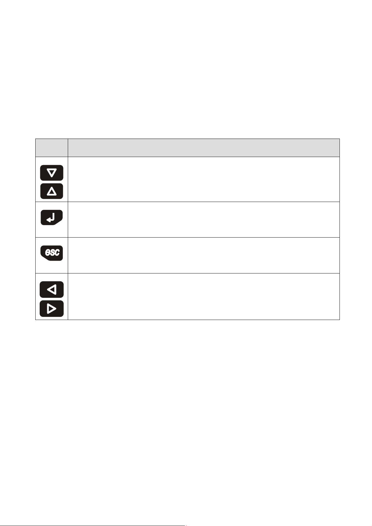
The keyboard features 6 page navigation and value editing keys, which have the following functions:
Symbol
Functions
In editing, it modifies parameters; otherwise, it moves the cursor.
During editing, it confirms the value; otherwise, it sends any commands associated to the text where the
cursor is positioned.If pressed down and held for about 2 seconds, the ENTER key enables access to the main menu.
If held down during display of an alarm page, this key enables resetting of the alarm.If alarm pages are being
displayed, every key press scrolls all active alarms.
During editing, it cancels the value; otherwise, it requests any default page that might e associated with the current
page.If pressed down and held for about 2 seconds, the ESC key enables ON/OFF switching of the machine.
If pressed in the main page, this key will display the list of all active alarms.
It displays the pages of the same level in succession.
page 12 of 120

EVCO S.p.A.
c-pro 3 micro CHIL | Application manual ver. 1.0 | Codice 144CP3CHE104
6 LIST OF PAGES
This chapter describes the main pages and menus featured in the application. As already described earlier, the general menu is
subdivided into four submenu levels: user, maintenance operator, installation operator, and configuration.
The menu structure is the following:
Menu
General Menu
Maintenance Menu
(Level 2)
Installer Menu
(Level 3)
Constructor Menu
(Level 4)
RTC Menu
Alarm Menu
User Menu (Level 1)
Operation
Manual
Calibration
Input/output
Compressors
Regulation
Fans
Defrost
Pumps
Anti-Freeze
Free-Cooling
Device safeties
Modbus
Various parameters
Configuration
Hardware configuration
EVDRIVE03 (Circuit 1, Circuit 2)
Function of the menu
page 13 of 120

EVCO S.p.A.
c-pro 3 micro CHIL | Application manual ver. 1.0 | Codice 144CP3CHE104
6.1 Password
Each menu is assigned a level, which affects the accessibility of the various menus.
Each level is assigned a password, which enables access to the various functions featured in that menu; once the correct password has
been entered, protected functions become accessible. Entering of the correct password has two consequences:
• Unlocking of the related level;
• Unlocking of its sublevels.
All level passwords can be modified from the same level or from higher levels. For example, from the constructor level it will be possible
to modify all passwords of underlying levels, by using the appropriate page.
The range of values that can be set for a password is -999 / 9999.
After 4 minutes have elapsed without any key being pressed, the password expires and it is necessary to reset it.
6.2 Unit OFF main page
The main display page varies according to the machine status, i.e. on or off:If the machine is switched OFF, Unit OFF is displayed, with
indication of the cause for the shutdown (keyboard, DI, Supervisor, Scheduler, Alarm, Change-Over).
Pressing the ESC key from this page brings the user to the Alarm page.
page 14 of 120
EVCO S.p.A.
c-pro 3 micro CHIL | Application manual ver. 1.0 | Codice 144CP3CHE104
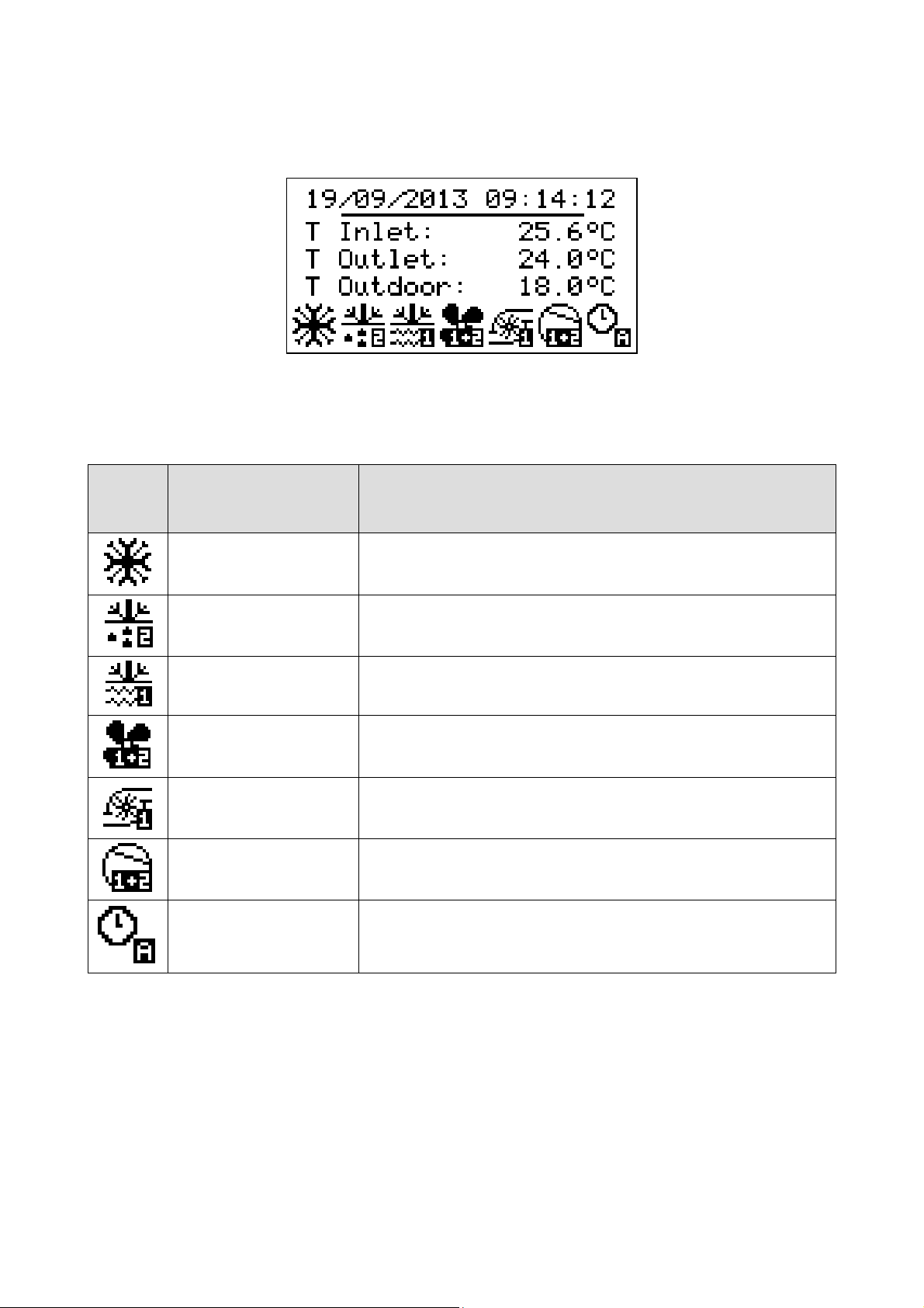
6.3 Unit ON main page
When the unit is turned on, the following main screen will be displayed:
At the bottom of the page, icons will be displayed that indicate various statuses of circuit operation.
The table below contains graphic representations of the individual icons, the relative operational status and what is being verified.
From left to right:
Icon
Operational status
Eventdisplayed
Summer/Winter/Alarm Icon
Defrost Icon
Antifreeze Icon
Fan Icon Indicates that the circuit fans (1,2, 1+2) are active
Pump Icon Indicates which circulation pump (1,2) is active
Compressor Icon Indicates that at least one circuit compressor (1,2, 1+2) is active
Time Slot Icon Indicates which time slot is active (A,B)
From this page, by pressing the RIGHT or LEFT keys, it is possible to display other information regarding pumps, fans, compressors,
defrost, circuit status, RTC and all configured sensors. In case of fault status of the sensors, the value field of the corresponding sensor
displays “----“, or else “----“ if the sensor is disabled.
Pressing the ESC key from this page brings the user to the Alarm page.
In case there is an active alarm, the alarm icon will be displayed alternatively with
the icon of the operational mode (summer/winter)
Indicates that circuit defrost is in progress (1,2).
If flashing, it is in dripping phase
Indicates that the antifreeze resistance mechanism is active (heat sink or source)
in the circuit indicated (1,2 1+2)
page 15 of 120

EVCO S.p.A.
c-pro 3 micro CHIL | Application manual ver. 1.0 | Codice 144CP3CHE104
6.4 Menu StAt (Only for display LED)
If the StAt voice is chosen from the general menu, several main statuses of the system are displayed (can be navigatedwith the
Left/Right buttons) on the reference page:
Exampletable of system statuses displayed on Page 1
Reference page Status displayed System status
Page 1 Unit Indicates the status in which the machine operates (OFF, ChIL, pdC, dEFr, dRIp, F-C)
Page 1 ModE Indicates the operational mode of the machine (ChIL, pdC)
Page 1 tdF1 Accumulation of wait time for defrost circuit 1
Page 1 dFr1 Duration of circuit defrost 1
Page 1 tdF2 Accumulation of wait time for defrost circuit 2
Page 1 dFr2 Duration of defrostcircuit 2
Page 1 SEtC Summer mode current set point
Page 1 SEtH Winter mode current set point
Page 1 rEGP Main regulation probe
Page 1 PREq Power required [%]
Page 1 PSup Power supplied[%]
Example table of system statuses displayed on Page 2
Reference page Status displayed System status
Page 2 CMP1, CMP2 .. CMP6 Status of compressors (dIS, OFF, tOn, On, tOFF, ALAr, MAnU)
Page 2
Page 2
Page 2
Page 2
Page 2
Page 2
Page 2
Page 2
Page 2
Sample table of system statuses displayed on Page 3
Reference page Status displayed System status
Page 3 tExt External temperature probe
Page 3
Page 3
Page 3
Page 3
Page 3
Page 3
Page 3
Page 3
Page 3
Page 3
Page 3
FAn1, FAn 2 Status of fans (dIS, OFF, tOn, On, tOFF, ALAr, MAnU)
InF1,InF2 Speed of condenser fans [%]
PMP1, PMP2 Status of pumps (dIS, OFF, On, ALAr, MAnU)
PMS1, PMS2 Status of heat source pumps (dIS, OFF, On, ALAr, MAnU)
F-C Status of free-cooling activation
vF-C Free-cooling valve
FF-C Free-cooling regulation
vpC1 Status of C1splitter valve for free-cooling
vpC2 Status of C2 splitter valve for free-cooling
tAux Remote temperature probe
tiFc Machine input temperature probe (Free-Cooling)
tin Heat sink exchanger input temperature probe
toC1/2 Heat sink exchanger output temperature probe (circuit 1,2)
toS1/2 Heat source exchanger input temperature probe (circuit 1,2)
tCo1/2 Coil temperature probe (circuit 1,2)
GAS1/2 Exhaust gas compressor temperature probe (circuit 1,2)
tSu1/2 Intake compressor temperature probe (circuit 1,2)
PCO1/2 Condensing pressure probe (circuit 1,2)
PEV1/2 Evaporation pressure probe (circuit 1,2)
Pun1/2 Single pressure probe (circuit 1,2)
page 16 of 120

EVCO S.p.A.
c-pro 3 micro CHIL | Application manual ver. 1.0 | Codice 144CP3CHE104
Pressing ENTER on the label causes the value of the relative status to be displayed;pressing ESC brings you back to the general menu
screen. This menu is not protected by a password.
6.4.1 Meaning of LED (only for display LED)
The LED display offers several icons that display particular statuses of the unit:
• OnOff. If on, it means that the unit has no power; if off, it means that the unit is on; if on with slow flashing light, it means
that the unit is not being powered by the Scheduler; if on with fast flashing light, it means that the unit is not being powered
by the Supervisor or Digital Input.
• Snow. If on, summer/winter function (seeparameter PH53); if on and flashing, the free-cooling function is active.
• Sun. If on, summer/winter function (see parameter PH53).
• Alarm. If on, the function indicates the presence of alarms; if on and flashing, it indicates the presence of new alarms not
displayed yet; if off, there are no alarms.
• Defrost. If on, it means that defrosting is active in one of the 2 circuits; if on and flashing, it means that draining is active in
one of the2 circuits
• Maintain. If on, it means that at least one device is functioning manually; if on and flashing, it means that a “device
operating hours” alarm is active.
• Compressor 1. If on, it means that at least one compressor of circuit 1 is active; if off, it means that no circuit compressors
are active; if on and flashing slowly, it means that a circuit compressor is in the alarm state; if on and flashing quickly, it
means that a circuit compressor is in manual mode.
• Compressor 2. If on, it means that at least one compressor of circuit 2 is active; if off, it means that no circuit compressors
are active; if on and flashing slowly, it means that a circuit compressor is in the alarm state; if on and flashing quickly, it
means that a circuit compressor is in manual mode.
• Pump. If on, it means that a heat sink pump is active; if off, it means that no pumps are active; if on and flashing slowly, it
means that a pump is in the alarm state; if on and flashing quickly, it means that a pump is in manual mode.
• Fan. If on, it means that one fan is active; if off, it means that no fans are active; if on and flashing slowly, it means that a
fan is in the alarm state; if on and flashing quickly, it means that a fan is in manual mode.
• Heaters: If on, it means that the strength of the antifreeze mechanism (heat sink or source) is active; if off, it means that no
antifreeze mechanisms are active; if on and flashing slowly, it means that an antifreeze mechanism is in the alarm state.
• EVCO. Icon linked to the functioning of parameter PH52.
page 17 of 120

EVCO S.p.A.
c-pro 3 micro CHIL | Application manual ver. 1.0 | Codice 144CP3CHE104
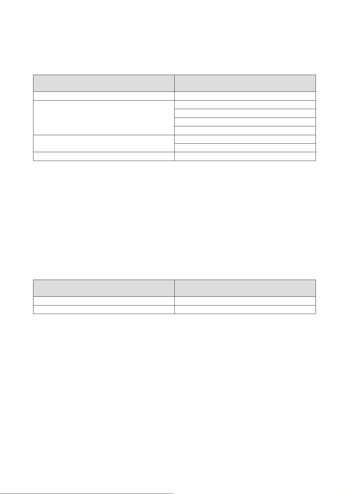
6.5 General Menu
The general menu has no level and represents the access point for all the other system menus.
Display LCD Display LED
USER USEr
MAINTENANCE MAin
INSTALLER InSt
CONSTRUCTOR CoSt
RTC rTC
ALARMS ALrm
HISTORY HiSt
Not present StAt
It is possible to view this menu from any point within the user interface by pressing ENTER for approximately 2 seconds. From this
menu you can choose the menu you wish to view by pressing the UP and DOWN keys followed by pressing the ENTER key for
confirmation.
In the upper right hand corner of the image appears a “v” which represents the focus.
This indication specifies to the user that additional information is contained therein and can be viewed by pressing the DOWN key (or
UP key depending on the direction of the focus) scrolling to view the content that is not viewable in the current page.
6.6 User Menu
The User menu is a Level 1 menu, i.e. it requires entering of the User level (or higher) password, in order to be able to display/modify
the parameters contained in this branch.
6.7 Maintenance Menu
The Maintenance menu is a Level 2 menu, i.e. it requires entering of the Maintenance operator level (or higher) password, in order to
be able to display/modify the parameters contained in this branch.
Display LCD Display LED
OPERATION OPEr
MANUAL MAnU
CALIBRATION CAL
IN/OUT I-O
PASSWORD PSd2
In this menu, it is possible to view the status of the various devices, inputs and outputs utilized by the application.
In the OPERATION menu, it is possible to view/enable the features relating to the operation of compressors, fans and pumps. Some
examples of these are the hours of operation, the threshold of maximum allowable hours.
In the MANUAL menu, it is possible to set to manual/automatic operation compressors, pumps and fans, whose outputs can be forced,
in order to test their functionality.
In the CALIBRATION menu, it is possible to set the corrections to be applied to analogue inputs, to compensate the offsets due to
cabling and sensor positioning.
In the I/O STATUS menu, it is possible to view directly the card’s physical inputs and outputs
page 18 of 120

EVCO S.p.A.
c-pro 3 micro CHIL | Application manual ver. 1.0 | Codice 144CP3CHE104
6.8 Installer Menu
The installation menu is a Level 3 menu, i.e. it requires entering of the installation level (or higher) password, in order to be able to
display/modify the parameters contained in this branch.
Display LCD Display LED
COMPRESSORS CoMP
REGULATION rEG
FANS FANS
DEFROST dEFr
PUMPS PuMP
ANTI-FREEZE A-F
FREE-COOLING F-C
SAFETIES SAFE
MODBUS MdbS
VARIOUS Par
SAVE/RESTORE MAp
PASSWORD PSd3
The installation operator menu contains all the parameters connected with the configuration of all functionalities (alarms, settings,
logic, rotation type, etc.) of the machine.
In the REGULATION menu, it is possible to set the parameters connected with lateral-band and zero energy band temperature control
of compressors.
In the COMPRESSORS menu, it is possible to set the parameters connected with the management of devices:
• rotation
• timings
• maximum number of start-ups.
In the FANS menu, it is possible to set the parameters connected with the control of condensation pressure, via the fans.
In the DEFROST menu, it is possible to set the parameters connected with the activation and duration of heat pump defrosting.
In the PUMP menu, it is possible to set the parameters connected with operation and protection of pumps.
In the ANTI-FREEZE menu, it is possible to set the parameters connected with the thermal control of resistors and control of the anti-
frost alarm.
In the FREE-COOLING menu, it is possible to set the parameters connected with free-cooling function and damper.
The SAFETIES DEVICES menu contains all parameters connected with alarms and management of safety devices which protect the
refrigerating circuit:
• activations
• reporting delays
• type of resetting.
In the MODBUS menu it is possible to set the parameters connected with modbus.
The VARIOUS PARAMETERS menu contains other general parameters connected with the management of Modbus communications,
transducer full-scale values and other configurable activations.
From the SAVE/RESTORE menu it is possible to restore the default values of all parameters of the application and save or download
from the programming key or internal controller memory.
page 19 of 120
EVCO S.p.A.
c-pro 3 micro CHIL | Application manual ver. 1.0 | Codice 144CP3CHE104
6.9 Constructor Menu
The Configuration menu is a Level 4 menu, i.e. it requires entering of the Configuration level password, in order to be able to
display/modify the parameters contained in this branch. Furthermore, this level is only accessible with the machine in OFF mode.
Display LCD Display LED
CONFIGURATION COnF
H-AI
HARDWARE
EVCM C1-C2
PASSWORD PSd
This menu contains all the machine’s configuration parameters, which determine its operation mode and which functionalities are to be
enabled or disabled.
The CONFIGURATION menu contains the parameters machine configuration.
The HARDWARE menu allows to configure the I/O of the unit.
The EVCM menu allows to configure the main parameters of EVDRIVE03 for each Circuit.
H-dI
H-AO
H-dO
vCM1
vCM2
6.10 RTC Menu
This menu contains the functionality of the systems Real Time Clock, as setting the real time clock and setting daily scheduler (PTxx
parameters).
6.11 Alarms Menu
This menu allows viewing and acknowledging of alarms.
Display LCD Display LED
Show Alarms ALrm
Show History HiSt
The SHOW ALARMS menu shows the active alarms. Each time the DOWN key is pressed, the next active alarm is shown. If no alarms
are present, the message “NO ALARMS” is displayed.
The alarm can be acknowledged by pressing the ENTER key for 2 seconds, when the alarm condition is not active anymore.
The ALARM HISTORY page will show the latest alarm. To view the preceding alarm press ENTER key. This can be repeated until the first
alarm is displayed. The history is viewed in a circular manner.
By pressing the ESC key or after 60 seconds of no key activity, the main page will be displayed.
page 20 of 120
EVCO S.p.A.
c-pro 3 micro CHIL | Application manual ver. 1.0 | Codice 144CP3CHE104
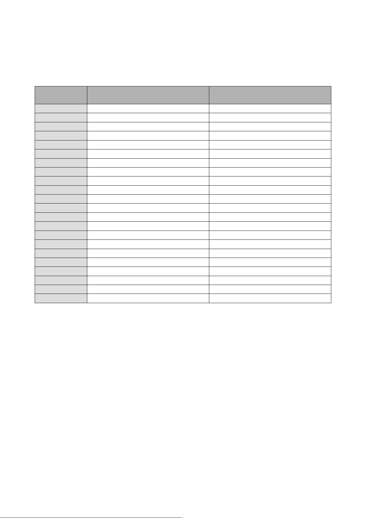
7 PARAMETERS LIST
The parameters managed by the application are listed below. Each parameter is accompanied by a brief description, the range of its
admissible values, units of measure, the assigned default value and the menu containing the parameter. Menus are structured on the
basis of the following logic:
Menu code Reference menu Status
OR RTC menu
UT User menu
MA Maintenance menu
MA-F Maintenance menu Operation
MA-M Maintenance menu Manual
MA-C Maintenance menu Calibration
MA-IO Maintenance menu Input/Output
IS Installation menu
IS-C Installation menu Compressors
IS-R Installation menu Regulation
IS-F Installation menu Fans
IS-D Installation menu Defrost
IS-P Installation menu Pumps
IS-AF Installation menu Anti-freeze
IS-FC Installation menu Free-Cooling
IS-S Installation menu Safeties
IS-M Installation menu Modbus
IS-V Installation menu Various
CO Configuration menu
CO-W Configuration menu Configuration
CO-HW Configuration menu Hardware
CO-V Configuration menu EVDRIVE03 circuit 1 and EVDRIVE03 circuit 2
page 21 of 120
EVCO S.p.A.
c-pro 3 micro CHIL | Application manual ver. 1.0 | Codice 144CP3CHE104
7.1 List of Configuration Parameters
Code
PT01 Working day 1 enable zone 1 0 0 1 OR
PT02 Working day 1 zone 1 start time 0
PT03 Working day 1 zone 1 stop time 0
PT04 Working day 1 zone 1 cooling offset 0 -20.0 20.0 °C OR
PT05 Working day 1 zone 1 heating offset 0 -20.0 20.0 °C OR
PT06 Working day 1 enable zone 2 0 0 1 OR
PT07 Working day 1 zone 2 start time 0
PT08 Working day 1 zone 2 stop time 0
PT09 Working day 1 zone 2 cooling offset 0 -20.0 20.0 °C OR
PT10 Working day 1 zone 2 heating offset 0 -20.0 20.0 °C OR
PT11 Working day 2 enable zone 1 0 0 1 OR
PT12 Working day 2 zone 1 start time 0
PT13 Working day 2 zone 1 stop time 0
PT14 Working day 2 zone 1 cooling offset 0 -20.0 20.0 °C OR
PT15 Working day 2 zone 1 heating offset 0 -20.0 20.0 °C OR
PT16 Working day 2 enable zone 2 0 0 1 OR
PT17 Working day 2 zone 2 start time 0
PT18 Working day 2 zone 2 stop time 0
PT19 Working day 2 zone 2 cooling offset 0 -20.0 20.0 °C OR
PT20 Working day 2 zone 2 heating offset 0 -20.0 20.0 °C OR
PT21 Monday schedule 1 0 2 OR
PT22 Tuesday schedule 1 0 2 OR
PT23 Wednesday schedule 1 0 2 OR
PT24 Thursday schedule 1 0 2 OR
Parameter Description Default Min. Max. M.U. Menu Notes
RTC MEN - This menu
is accessible ifPG03=1
00:00:0
0
00:00:0
0
00:00:0
0
00:00:0
0
00:00:0
0
00:00:0
0
00:00:0
0
00:00:0
0
page 22 of 120
23:59:59 OR
23:59:59 OR
23:59:59 OR
23:59:59 OR
23:59:59 OR
23:59:59 OR
23:59:59 OR
23:59:59 OR
0= none
working day
1= working
day1
2= working
day2
0= none
working day
1= working
day1
2= working
day2
0= none
working day
1= working
day1
2= working
day2
0= none
working day
1= working
EVCO S.p.A.
c-pro 3 micro CHIL | Application manual ver. 1.0 | Codice 144CP3CHE104
PT25 Friday schedule 1 0 2 OR
PT26 Saturday schedule 0 0 2 OR
PT27 Sunday schedule 0 0 2 OR
Level
1
It sets the operating mode:
ModE
0: Cool, (Chiller/summer)
1: Heat (Heat pump/winter)
SPC1
SPH1
PUC1
PUH1
PSd1
It sets the value of the summer set
point (chiller)
It sets the value of the winter set
point (heat pump).
Offset for the summer set point by
digital input
Offset for the winter set point by
digital input
It modifies the password at User
level.
Level
2
OPERATION
It sets the maximum number of
PM00
operating hours of compressors.
When this limit is exceeded, the
connected alarm is triggered.
PM01
PM02
PM03
PM04
PM05
It shows the number of operating
hours of compressors. One parameter
for each compressor.
PM06
PM30
It sets the maximum number of
operating hours of pumps. When this
USER MENU
0 0 1 UT
8.5 PC21 PC22 °C UT
44.0 PC23 PC24 °C UT
2.0 -20.0 20.0 °C UT
-2.0 -20.0 20.0 °C UT
0 -999 9999 UT
MAINTENANCE MENU
2000 0 9999 Hrs. x10 MA-F
0 0 9999
Hrs.
x10
2000 0 9999 Hrs. x10 MA-F
day1
2= working
day2
0= none
working day
1= working
day1
2= working
day2
0= none
working day
1= working
day1
2= working
day2
0= none
working day
1= working
day1
2= working
day2
Modifiable
only if the
units is a
chiller + heat
pump:
(PG00=2,4)
MA-F
page 23 of 120

EVCO S.p.A.
c-pro 3 micro CHIL | Application manual ver. 1.0 | Codice 144CP3CHE104
limit is exceeded, the connected
alarm is triggered.
PM31
PM32
PM33
PM34
PM40
PM41
PM42
PM43
PM90 Last maintenance date - MA-F
PM11
PM12
PM13
PM14
PM15
PM16
PM21
PM22
PM23
PM24
PM25
PM26
PM35
PM36
PM37
PM38
PM45
PM46 It enables the manual/automatic 0 0 1 MA-M Only for
It shows the number of operating
hours of the first pump.
It shows the number of operating
hours of the second pump.
It shows the number of operating
hours of the first source pump.
It shows the number of operating
hours of the second source pump.
It sets the maximum number of
operating hours of fans. When this
limit is exceeded, the connected
0 0 9999 Hrs. x10 MA-F
0 0 9999
0 0 9999
0 0 9999
Hrs. x10
Hrs. x10
Hrs. x10
MA-F
MA-F
MA-F
Hrs. x10
2000 0 9999
MA-F
alarm is triggered.
It shows the number of operating
hours of the first fan or of the inverter
0 0 9999
Hrs. x10
MA-F
in Circuit # 1.
It shows the number of operating
hours of the second fan or of the
0 0 9999
Hrs. x10
MA-F
inverter in Circuit # 2.
It shows the number of operating
hours of the free-coolind dedicated
0 0 9999
Hrs. x10
MA-F
fan
MANUAL
It enables the manual/automatic
operation of the compressor.
0: Auto – normal operation
0 0 1 MA-M
1: Manu – manual operation
One for each compressor.
During manual operation, it forces the
start-up/shutdown of the compressor.
0: switches the compressor OFF
0 0 1 MA-M
1: switches the compressor ON
One for each compressor.
It enables the manual/automatic
operation of the pump # 1.
0: Auto – normal operation
0 0 1 MA-M
1: Manu – manual operation
It enables the manual/automatic
operation of the pump # 2.
0: Auto – normal operation
0 0 1 MA-M
1: Manu – manual operation
During manual operation, it forces the
start-up/shutdown of pump #1
During manual operation, it forces the
start-up/shutdown of pump #2
0 0 1 MA-M
0 0 1 MA-M
It enables the manual/automatic
operation of the source pump # 1.
0: Auto – normal operation
0 0 1 MA-M
1: Manu – manual operation
Only for
Water-Water
unit
page 24 of 120

EVCO S.p.A.
c-pro 3 micro CHIL | Application manual ver. 1.0 | Codice 144CP3CHE104
operation of the source pump # 2.
0: Auto – normal operation
1: Manu – manual operation
PM47
PM48
During manual operation, it forces the
start-up/shutdown of source pump #1
During manual operation, it forces the
start-up/shutdown of source pump #2
0 0 1 MA-M
0 0 1 MA-M
It enables the manual/automatic
operation of the condensing fan in
PM51
Circuit # 1.
0 0 1 MA-M
0: Auto – normal operation
1: Manu – manual operation
It enables the manual/automatic
operation of the condensing fan in
PM52
Circuit # 2.
0 0 1 MA-M
0: Auto – normal operation
1: Manu – manual operation
During manual operation, it forces the
PM61
value of the condensing fan in Circuit
0 0 100 % MA-M
#1.
During manual operation, it forces the
PM62
value of the condensing fan in Circuit
0 0 100 % MA-M
#2.
During manual operation, it forces the
PM63
value of the condensing fan in Circuit
0 0 1 MA-M
#1.
During manual operation, it forces the
PM64
value of the condensing fan in Circuit
0 0 1 MA-M
#2.
It enables the manual/automatic
operation of the dedicated free-
PM65
ccoling fan:
0 0 1 MA-M
0: Auto – normal operation
1: Manu – manual operation
During manual operation, it forces the
PM66
value of the dedicated free-cooling
0 0 100 % MA-M
fan
During manual operation, it forces the
PM67
value of the dedicated free-cooling
0 0 1 MA-M
fan
CALIBRATION
PM71
PM72
Calibration of external temperature
sensor
Calibration of free-cooling input
temperature sensor
0.0 -10.0 10.0 °C MA-C
0.0 -10.0 10.0 °C MA-C
PM73 Calibration of entering temperature 0.0 -10.0 10.0 °C MA-C
Water-Water
unit
Only for
Water-Water
unit
Only for
Water-Water
unit
With PF01=1
(Modulating
Control)
With PF01=1
(Modulating
Control)
With PF01=0
(Single stage
Control)
With PF01=0
(Single stage
Control)
Only for
Chillers
Air-Water unit
When PG13>0
Only for
Chillers
Air-Water unit
When PG13=1
Only for
Chillers
Air-Water unit
When PG13=2
page 25 of 120
EVCO S.p.A.
c-pro 3 micro CHIL | Application manual ver. 1.0 | Codice 144CP3CHE104
sensor
PM74
PM75
PM76
PM77
PM78
PM79
PM80
PM81
PM82
PM83
PM84
PM85
PM86
PM87
PM88
PSd2
Level
PC01
PC02
PC04
PC05
PC06
Calibration of leaving temperature
sensor circuit 1
Calibration of leaving temperature
sensor circuit 2
Calibration of source leaving
temperature sensor circuit 1
Calibration of source leaving
temperature sensor circuit 2
Calibration of coil temperature sensor
circuit 1
Calibration of coil temperature sensor
circuit 2
Calibration of discharge compressors
temperature sensor circuit 1
Calibration of discharge compressors
temperature sensor circuit 2
Calibration of remote
aux.temperature sensor
Calibration of condensing pressure
sensor circuit 1
Calibration of condensing pressure
sensor circuit 2
Calibration of evaporatorating
pressure sensor circuit 1
Calibration of evaporatorating
pressure sensor circuit 2
Calibration of unique pressure sensor
circuit 1
Calibration of unique pressure sensor
circuit 2
It modifies the password at
Maintenance Operator level.
3
INSTALLATION MENU
0.0 -10.0 10.0 °C MA-C
0.0 -10.0 10.0 °C MA-C
0.0 -10.0 10.0 °C MA-C
0.0 -10.0 10.0 °C MA-C
0.0 -10.0 10.0 °C MA-C
0.0 -10.0 10.0 °C MA-C
0.0 -10.0 10.0 °C MA-C
0.0 -10.0 10.0 °C MA-C
0.0 -10.0 10.0 °C MA-C
0.0 -20.0 20.0 Bar MA-C
0.0 -20.0 20.0 Bar MA-C
0.0 -20.0 20.0 Bar MA-C
0.0 -20.0 20.0 Bar MA-C
0.0 -20.0 20.0 Bar MA-C
0.0 -20.0 20.0 Bar MA-C
0 -999 9999 MA-F
COMPRESSORS
Rotation type used for compressor
management:
0: FIFO
1: LIFO
0 0 3 IS-C
2: FIFO + hours
3: LIFO + hours
Enabling mode of compressors in the
two circuits:
0: Circuit balancing
0 0 1 IS-C
1: Circuit saturation
Min. time for which the compressor
must remain ON, even if a shutdown
20 0 999 Sec. IS-C
has been requested.
Min. time for which the compressor
must remain OFF, even if a start-up
120 0 999 Sec. IS-C
has been requested.
Min. time which must elapse between
two start-ups of the same
360 0 999 Sec. IS-C
Only on twin
circuits
page 26 of 120

EVCO S.p.A.
c-pro 3 micro CHIL | Application manual ver. 1.0 | Codice 144CP3CHE104
compressor.
Min. time which must elapse between
PC07
PC08
PC09
PC10
REGULATION
PC11
PC12
PC14
PC15
PC16
PC17
PC18
PC21
PC22
PC23
PC24
PC31 Power limiting for summer 50 0 100 % IS-R
PC32 Power limiting for winter 50 0 100 % IS-R
PC35
PC36 Summer forced shutdown set point 3.5 -30.0 23.0 °C IS-R
PC37 Winter forced shutdown set point 52.0 26.0 75.0 °C IS-R
PC41
PC42
PC43
PC45
start-ups of two different
compressors.
Min. time which must elapse between
shutdowns of two different
compressors.
Max. number of start-ups for every
hour (only for adaptive control).
Number of compressors per circuit
which will be forced in case of a
regulating-sensor alarm.
It sets the control type for
compressor management:
0: Lateral band
1: Zero energy band
Proportional band for lateral-band
control of compressors
Zone value for neutral-zone control of
compressors
Min. value of compressor zero energy
band
Max. value of compressor zero energy
band
Enabling/release time for subsequent
compressor step outside the zero
energy band
Enabling for auto-adaptive control of
the compressors’ zero energy band
Min. value of summer set point
(chiller)
Max. value of summer set point
(chiller)
Min. value of winter set point
(heat pump)
Max. value of winter set point
(heat pump)
Enabling of forced shutdown of
compressors
Enabling of pump-down
0 : No
1 : Yes, with timing
2 : Yes, with relative threshold
Compressor shutdown time in pump-
down
Relative threshold for pump-down
disabling
Enabling of high-temperature
pressure-switch control (chiller)
360 0 999 Sec. IS-C
180 0 999 Sec. IS-C
8 4 12 IS-C
1 0 PG03 IS-C
1 0 1 IS-R
2.5 1.0 20.0 °C IS-R
3.0 PC15 PC16 °C IS-R
1.0 0.1 10.0 °C IS-R
5.0 0.1 10.0 °C IS-R
20 0 999 Sec. IS-R
No (0) No (0) Yes (1) IS-R
5.0 -15.0 SPC1 °C IS-R
20.0 SPC1 23.0 °C IS-R
30.0 23.0 SPH1 °C IS-R
44.0 SPH1 70.0 °C IS-R
No (0) No (0) Yes (1) IS-R
1 0 2 IS-R
5 0 240 Sec. IS-R
1.5 0.0 5.0 Bar IS-R
No (0) No (0) Yes (1) IS-R
page 27 of 120

EVCO S.p.A.
c-pro 3 micro CHIL | Application manual ver. 1.0 | Codice 144CP3CHE104
PC46
PC47
PC48
PC49
PC50
PC51
PC52
PC53
PC54
PC55
Pressure set point for high-
temperature pressure-switch control
Pressure differential for high-
temperature pressure-switch control
External high temperature threshold
for pressure-switch control
Min. time for maintaining pressure-
switch partialization
Enabling of low-temperature
pressure-switch control (heat pump)
Pressure setpoint for low-temperature
pressure-switch control
Pressure differential for low-
temperature pressure-switch control
External low temperature threshold
for pressure-switch control
Outlet water high-temperature
threshold for pressure-switch control
Delay for partialization from low
pressure alarm
27.0 0.0 45.0 Bar IS-R
2.0 0.0 5.0 Bar IS-R
12.0 -30.0 23.0 °C IS-R
10 0 99 Min. IS-R
No (0) No (0) Yes (1) IS-R
3.2 0.0 10.0 Bar IS-R
2.0 0.0 10.0 Bar IS-R
-5.0 -10.0 5.0 °C IS-R
48.0 30.0 70.0 °C IS-R
900 0 999 Sec. IS-R
PC61 Summer commutation set point 20.0 PC62 70.0 °C IS-R
PC62 Winter commutation set point 10.0 0.0 PC61 °C IS-R
PC64
PC65
PC66
PC67
PC68
PC69
Max. dynamic offset compared to
summer set point (chiller)
Compensation start temperature for
dynamic summer set point
Compensation stop temperature for
dynamic summer set point
Max. dynamic offset compared to
winter set point (heat pump)
Compensation start temperature for
dynamic winter set point
Compensation stop temperature for
dynamic winter set point
-10.0 -20.0 20.0 °C IS-R
30.0 -15.0 PC66 °C IS-R
60.0 PC65 70.0 °C IS-R
10.0 -20.0 20.0 °C IS-R
0.0 -15.0 PC69 °C IS-R
30.0 PC68 70.0 °C IS-R
Function limit management:
PC70
0 = Heat pump only
1 = Auxiliary output
0 0 2 IS-R
2 = Auxiliary output and heat pump
PC71 Function limit set point -7.0 -30.0 30.0 °C IS-R
PC72 Function limit differential 4.0 0.1 10.0 °C IS-R
PC80 Enabling of control upon request No (0) No (0) Sì (1) IS-R
PC81 Summer setpoint controlupon request 15.0 -15.0 70.0 °C IS-R
PC82 Winter setpoint control upon request 45.0 -15.0 70.0 °C IS-R
PC83
Summer differential control upon
request
4.0 0.1 10.0 °C IS-R
PC84 Winter differential control upon request 4.0 0.1 10.0 °C IS-R
PC85 Delayed control upon request 5 0 999 Sec IS-R
FANS
PF01 Condenser control type 0 0 1 IS-F
PF02 It gives the choice to enable fan Yes (1) No (0) Yes (1) IS-F
0=Modulating
control
1=Single
stage control
page 28 of 120

EVCO S.p.A.
c-pro 3 micro CHIL | Application manual ver. 1.0 | Codice 144CP3CHE104
control only if at least one compressor
is ON.
PF03
PF07
PF08
PF09
PF10
PF11
PF12
PF13 Enabling of forcing to maximum Yes (1) No (0) Yes (1) IS-F
PF14
PF15
PF16
PF21
PF22
PF24
PF25
PF26
PF27
PF28
PF31
PF32
PF33
PF34
PF36
It sets whether or not fans must
switch OFF during defrosting cycles.
Min. time which must elapse between
the start-ups of two different fans.
Min. time which must elapse between
the shutdowns of two different fans.
Forcing of fans in case of condensing
sensor alarm
Forcing of fans in case of condensing
sensor alarm
Condensing control set point for
summer operation (chiller)
Linear control band for condensation
in summer operation (chiller)
Max. forcing enabling set point in
summer operation (chiller)
Disabling differential for max. forcing
in summer operation (chiller)
Integral time for control of valves
(cooling)
Condensing control set point in winter
operation (heat pump)
Linear control band for condensation
in winter operation (heat pump)
Max. forcing activation set point in
winter operation (heat pump,
inverter)
Max. forcing de-activation differential
in winter operation (heat pump,
inverter)
Integral time for control of valves
(heat pump)
Min. value for condenser forcing
(inverter)
Speed-up time at fan start-up
(inverter)
Lower limit for condensing linear
control (inverter)
Upper limit for condensing linear
control (inverter)
Enabling of control under the
minimum condensing limit (inverter)
Switch-off differential under the
minimum condensing limit (inverter)
Enabling of preventilation
0: No
1: Winter only
No (0) No (0) Yes (1) IS-F
10 0 999 Sec. IS-F
20 0 999 Sec. IS-F
No (0) No (0) Yes (1) IS-F
0.0 0.0 100.0 % IS-F
20.0 5.0 45.0 Bar IS-F
12.0 0.1 15.0 Bar IS-F
26.0 15.0 45.0 Bar IS-F
2.0 0.1 5.0 Bar IS-F
0 0 999 Sec IS-F
9.0 0.5 15.0 Bar IS-F
2.0 0.1 15.0 Bar IS-F
3.2 0.5 20.0 Bar IS-F
0.5 0.1 5.0 Bar IS-F
0 0 999 Sec IS-F
0.0 0.0 100.0 % IS-F
4 0 999 Sec. IS-F
30.0 0 PF32 % IS-F
100.0 PF31 100.0 % IS-F
Yes (1) No (0) Yes (1) IS-F
2.0 0.0 5.0 Bar IS-F
0 0 2 IS-F
With PF01=0
(Single stage
Control)
With PF01=1
(Modulating
Control)
If PF16=0
Integral action
not present
If PF26=0
Integral action
not present
page 29 of 120
EVCO S.p.A.
Only for Air
-
c-pro 3 micro CHIL | Application manual ver. 1.0 | Codice 144CP3CHE104
2: Always
PF38 Preventilation speed 50.0 0.0 100.0 % IS-F
PF39 Preventilation time 10 0 999 Sec IS-F
PF41 Value x1 of fan linearization table 25.0 0.0 PF42 % IS-F
PF42 Value x2 of fan linearization table 50.0 PF41 PF43 % IS-F
PF43 Value x3 of fan linearization table 75.0 PF42 100.0 % IS-F
PF45 Value y1 of fan linearization table 25.0 0.0 PF46 % IS-F
PF46 Value y2 of fan linearization table 50.0 PF45 PF47 % IS-F
PF47 Value y3 of fan linearization table 75.0 PF46 100.0 % IS-F
DEFROST
Pd01 Pressure set point at defrosting start 6.0 0.0 Pd02 Bar IS-D
Pd02 Pressure set point at defrosting stop 12.0 Pd01 45.0 Bar IS-D
Pd03 Waiting interval at defrosting start 1200 60 Pd23 Sec. IS-D
Pd05 Max. duration of defrosting 300 10 600 Sec. IS-D
Pd06 Duration of dripping 120 0 600 Sec. IS-D
Pd07
Pd20
Pd21
Pd22
Pd23
PUMPS
PP01
PP02 ON time in cyclical operation 120 1 999 Sec. IS-P
PP03 OFF time in cyclical operation 120 1 999 Sec. IS-P
PP04
PP05
PP07 Shutdown of pump during defrosting No (1) No (0) Yes (1) IS-P
PP08
PP09
PP10
PP21
ANTI-FREEZE
Min. defrost waiting interval after
compressor re-start
Enabling of defrosting cycle
compensation
Outdoor air temperature set point for
defrosting compensation start
Outdoor air temperature set point for
defrosting compensation stop
Max. waiting interval at defrosting
stop
Pump operation:
0 = Continuous operation
1 = Operation at thermostat’s request
2 = Cyclical operation
Min. interval which must elapse
between pump start-up and first
compressor
Min. interval which must elapse
between circuit shutdown and pump
Difference in operating hours between
the two pumps, requiring their being
swapped.
Pump operating time at low water
flow (flow alarm)
Pump operating time at low
temperature of outflow water (anti-
frost alarm)
Source Pump operation:
0= Continuous operation
1=Operation at thermostat’s request
2 = Cyclical operation
60 0 600 Sec. IS-D
No (0) No (0) Yes (1) IS-D
5.0 Pd22 70.0 IS-D
0.0 -30.0 Pd21 IS-D
3600 Pd03 9600 IS-D
0 0 2 IS-P
60 1 999 Sec. IS-P
60 1 999 Sec. IS-P
4 1 240 Hours IS-P
15 0 999 Sec. IS-P
15 0 999 Sec. IS-P
0 0 2 IS-P
With PF01=1
(Modulating
Control)
Water unit
Only for
Water-Water
unit
page 30 of 120
 Loading...