

Page 1

EVCO S.p.A. c-pro 3 micro SAVE/ c-pro 3 kilo SAVE | Application Manual ver. 1.0 | Code 144CP3UKSAE104
EVCO
c-pro 3 micro SAVE
c-pro 3 kilo SAVE
PROGRAMMABLE CONTROLLER FOR AIR
HANDLING UNITS WITH CROSS FLOW
HEAT RECOVERY EXCHANGER
ENGLISH
APPLICATION MANUAL ver. 1.0
CODE 144CP3UKSAE104
page 1 of 68
Page 2

EVCO S.p.A. c-pro 3 micro SAVE/ c-pro 3 kilo SAVE | Application Manual ver. 1.0 | Code 144CP3UKSAE104
EVCO
Important
Important
Read this document thoroughly before installation and before use of the device and follow all recommendations; keep
this document with the device for future consultation.
The following symbols support reading of the document:
indicates a suggestion
indicates a warning.
The device must be disposed of in compliance with local Standards regarding the collection of electric and electronic
equipment.
page 2 of 68
Page 3

EVCO S.p.A. c-pro 3 micro SAVE/ c-pro 3 kilo SAVE | Application Manual ver. 1.0 | Code 144CP3UKSAE104
EVCO
Index
1. GENERALITIES ........................................................................................................................................ 5
1.1
Description..................................................................................................................................... 5
2. DIMENSIONS AND INSTALLATION ............................................................................................................. 6
2.1
Dimensions .................................................................................................................................... 6
2.1.1 Dimensions of the control module c-pro 3 micro SAVE ..................................................................... 6
2.1.2 Dimensions of the control module c-pro 3 kilo SAVE ........................................................................ 6
2.1.3 Dimensions of the Vgraph user interface ........................................................................................ 7
2.2
Installation ..................................................................................................................................... 7
2.2.1 Installation of the control module c-pro 3 micro SAVE/c-pro 3 kilo SAVE ............................................ 7
2.2.2 Installation of the Vgraph user interface ........................................................................................ 8
3. Applications ............................................................................................................................................ 9
3.1
COMPACT Solution (make sure parameter PG00 has value 1; that is factory setting) ............................... 9
3.1.1 I/O Configuration with 3-speed fans .............................................................................................. 9
3.1.2 I/O Configuration with 1-speed fans with more speed variator ........................................................ 12
3.2
COMPLETE Solution (make sure parameter PG00 has value 2) ........................................................... 14
3.2.1 I/O Configuration with 3-speed fans ............................................................................................ 14
3.2.2 I/O Configuration with 1 speed fans + speed variator .................................................................... 17
4. User interface ....................................................................................................................................... 20
4.1
Display and keyboard .................................................................................................................... 20
4.1.1 Vgraph interface ....................................................................................................................... 20
4.2
List of pages ................................................................................................................................ 21
4.2.1 Main Menu ............................................................................................................................... 21
4.2.2 Password ................................................................................................................................. 21
4.2.3 User Menu ............................................................................................................................... 22
4.2.4 Installer Menu .......................................................................................................................... 22
4.2.5 RTC Menu ................................................................................................................................ 23
4.2.6 Manufacturer Menu ................................................................................................................... 23
4.2.7 Main OFF page ......................................................................................................................... 24
4.2.8 Main ON page .......................................................................................................................... 25
4.2.9 State Pages ............................................................................................................................. 26
4.2.10
Alarm pages ........................................................................................................................ 26
4.2.11
Log pages ............................................................................................................................ 26
4.2.12
Project and Firmware Versions ............................................................................................... 27
5. Configuration parameters ....................................................................................................................... 28
5.1
COMPACT solution list of configuration parameters ............................................................................ 28
5.2
COMPLETE solution list of configuration parameters .......................................................................... 34
6. REGULATIONS ...................................................................................................................................... 42
6.1
State of the unit ........................................................................................................................... 42
6.1.1 OFF state for alarm ................................................................................................................... 43
6.2
Unit Type ..................................................................................................................................... 43
6.3
RTC setting .................................................................................................................................. 43
6.4
Restore the (factory) default parameters ......................................................................................... 44
6.5
Last maintenance operation date .................................................................................................... 44
6.6
Programming key ......................................................................................................................... 45
6.7
Functionality of the COMPACT control solution .................................................................................. 46
6.7.1 Supply and return fans .............................................................................................................. 46
page 3 of 68
Page 4

EVCO S.p.A. c-pro 3 micro SAVE/ c-pro 3 kilo SAVE | Application Manual ver. 1.0 | Code 144CP3UKSAE104
EVCO
6.7.2
Recovery heat exchanger anti-freeze protection ........................................................................... 47
6.7.3 Cross flow recovery heat exchanger and by-pass damper .............................................................. 49
6.8
Features of the COMPLETE control solution ....................................................................................... 50
6.8.1 Post-Ventilation ........................................................................................................................ 50
6.8.2 Differential pressure switch ........................................................................................................ 50
6.8.3 Fresh air intake damper ............................................................................................................. 51
6.8.4 Damper mixing room ................................................................................................................ 51
6.8.5 Heating ................................................................................................................................... 52
6.8.6 Heat exchanger by-pass in summer mode (Free-Cooling) .............................................................. 54
6.8.7 Modulation of the air flow with CO2 probe .................................................................................... 55
6.8.8 Adjusting the static pressure ...................................................................................................... 55
6.8.9 Heating control depending on Return Air Temperature ................................................................... 56
6.8.10
Alarm fire/smoke .................................................................................................................. 56
7. DIAGNOSTICS ...................................................................................................................................... 56
7.1
Manual and automatic reset alarms ................................................................................................. 57
7.1.1 Manual reset alarms .................................................................................................................. 57
7.1.2 Automatic reset alarms ............................................................................................................. 57
7.2
Alarms table ................................................................................................................................. 57
7.3
General alarm relay ...................................................................................................................... 58
7.4
Alarms log ................................................................................................................................... 58
8. MODBUS VARIABLES ............................................................................................................................. 60
8.1
ModBus exporting table ................................................................................................................. 60
page 4 of 68
Page 5

EVCO S.p.A. c-pro 3 micro SAVE/ c-pro 3 kilo SAVE | Application Manual ver. 1.0 | Code 144CP3UKSAE104
EVCO
1. GENERALITIES
1.1 Description
The application is dedicated to the control and regulation of the Air Handling Units with cross flow recovery heat
exchanger. There are two solutions available:
• COMPACT Control: Responds to minimum requirements and the Standards.
• COMPLETE Control: Integrates the heating and high recovery efficiency functions to the Base solution.
The solution makes use of the large modularity of the c-pro 3 micro SAVE/c-pro 3 kilo SAVE
The c-pro 3 micro SAVE/c-pro 3 kilo SAVE controller has the following I/O:
• Digital outputs: 9
• Digital inputs: 9
• Analogical inputs: 9
• Analogical outputs: 6
Both instruments are equipped with CAN field port and a second RS485 serial interface (Modbus) allows connection to
BMS or EVCO (RICS) supervision systems.
The main control functions managed by the “Complete” solution are:
- Supply fan management
- Return fan management
- Management of the cross flow recovery heat exchanger by-pass damper
- Outside air damper management
- Management damper mixing room
- Management of hot water coil for heating (or a group of 3 electric heaters)
- Management of time bands with ECONOMY and COMFORT working mode
- CO
- Alarms log
- User Menu split in three main levels (User, Installer, Manufacturer), each protected by a different password.
- Multilanguage user menu (English, Italian, French)
probe management for fan control
2
page 5 of 68
Page 6

EVCO S.p.A. c-pro 3 micro SAVE/ c-pro 3 kilo SAVE | Application Manual ver. 1.0 | Code 144CP3UKSAE104
EVCO
2. DIMENSIONS AND INSTALLATION
2.1 Dimensions
2.1.1 Dimensions of the control module c-pro 3 micro SAVE
4 DIN modules;
dimensions are in mm (in). Terminal blocks molex-fit.
2.1.2 Dimensions of the control module c-pro 3 kilo SAVE
4 DIN modules;
dimensions are in mm (in). Terminal blocks removable spring
page 6 of 68
Page 7

EVCO S.p.A. c-pro 3 micro SAVE/ c-pro 3 kilo SAVE | Application Manual ver. 1.0 | Code 144CP3UKSAE104
EVCO
2.1.3 Dimensions of the Vgraph user interface
The dimensions are expressed in mm (in).
Dimension Minimum Typical Maximum
A 104.0 (4.094) 104.0 (4.094) 104.8 (4.125)
B 70.0 (2.755) 70.0 (2.755) 70.8 (2.787)
C 22.0 (0.866) 23.0 (0.905) 24.0 (0.944)
D 40.8 (1.606) 41.8 (1.645) 42.8 (1.685)
2.2 Installation
2.2.1 Installation of the control module c-pro 3 micro
SAVE/c-pro 3 kilo SAVE
On DIN guide 35.0 x 7.5 mm (1.377 x 0.295 in) or 35.0 x 15.0 mm (1.377 x 0.590 in).
Operate as indicated in the drawing below to install the devices.
1 2
page 7 of 68
Page 8

EVCO S.p.A. c-pro 3 micro SAVE/ c-pro 3 kilo SAVE | Application Manual ver. 1.0 | Code 144CP3UKSAE104
EVCO
To remove the devices, first remove any terminal board with extractable screws inserted in the lower part and then
operate on the DIN guide clip using a screwdriver, as indicated in the following drawing.
3 4
2.2.2 Installation of the Vgraph user interface
Installation is envisioned:
- on panel
- recessed in the wall in traditional box (506 E type)
- on the wall, on the EVCO CPVW00 support (to be ordered separately).
The following drawing illustrates panel installation, with 4 screws (supplied).
The EVCO CPVP* plaques can be applied to the terminal front panel (to be ordered separately, in plastic and available
in two colours, black and white).
page 8 of 68
Page 9

EVCO S.p.A. c-pro 3 micro SAVE/ c-pro 3 kilo SAVE | Application Manual ver. 1.0 | Code 144CP3UKSAE104
EVCO
3. Applications
3.1 COMPACT Solution (make sure parameter PG00 has
value 1; that is factory setting)
The picture above shows a principle layout. It is intended for indicating the presence of the components, not their
position, in the AHU controlled by the EVCO device. It is also NOT intended for indicating the real layout of the AHU.
The unit has the following main features:
• N° 2 Fans with 3 speeds or with 1 speed + speed variator
• N° 1 Heat exchanger/Cross flow recovery heat exchanger
• N° 1 Recovery heat exchanger By-pass damper (optional)
• N° 1 Recovery heat exchanger anti-freeze temperature probe
• N° 1 Presence sensor (installed in the room)
• N° 1 Start – Stop (remote)
Note: The compact solution is by default configured for piloting 3-speed fans (PG10 = DO)
3.1.1 I/O Configuration with 3-speed fans
c-pro 3 micro SAVE/ c-pro 3 kilo SAVE
I/O Description
Analogue inputs
AI 1 Anti-freeze Temperature Probe (Recovery heat exchanger By-Pass) NTC
AI 2 Not used
AI 3 Not used
AI 4 Not used
AI 5 Not used
AI 6 Not used
page 9 of 68
Page 10

EVCO S.p.A. c-pro 3 micro SAVE/ c-pro 3 kilo SAVE | Application Manual ver. 1.0 | Code 144CP3UKSAE104
EVCO
AI 7 Not used
AI 8 Not used
AI 9 Not used
Serial ports
RS485 RS485 Modbus RTU
CAN bus To Vgraph
Digital inputs
DI 1 Presence sensor
DI 2 Start – Stop (remote)
DI 3 Supply fan thermal protection
DI 4 Return fan thermal protection
DI 5 Not used
DI 6 Not used
DI 7 Not used
DI 8 Not used
DI 9 Not used
Analogue outputs
AO 1 Not used
AO 2 Not used
AO 3 Recovery heat exchanger BY-PASS damper control (0-10 V) *
AO 4 Not used
AO 5 Not used
AO 6 Mixing room damper control (0-10 V)
Digital Outputs (Relay)
DO 1 Return fan first speed
DO 2 Return fan second speed
DO 3 Return fan third speed
DO 4 Supply fan first speed
DO 5 Supply fan second speed
DO 6 Supply fan third speed
DO 7 Recovery heat exchanger BY-PASS damper control *
DO 8 Not used
DO 9 Not used
(*) The recovery heat exchanger BY-PASS damper control can be analogic or digital, and
setting with clock
RTC system clock - Real Time Clock.
For driving the 3-speed fans (Digital output) set PG10=DO
page 10 of 68
Page 11

EVCO S.p.A. c-pro 3 micro SAVE/ c-pro 3 kilo SAVE | Application Manual ver. 1.0 | Code 144CP3UKSAE104
EVCO
Electric connections with 3-speed fans
Note: These connections are also valid for the version, only changes the type of terminal and the supply voltage.
page 11 of 68
Page 12

EVCO S.p.A. c-pro 3 micro SAVE/ c-pro 3 kilo SAVE | Application Manual ver. 1.0 | Code 144CP3UKSAE104
EVCO
3.1.2 I/O Configuration with 1-speed fans with more speed
variator
c-pro 3 hecto + CAN with 2 A/O V+V
I/O Description
Analogue inputs
AI 1 Anti-freeze Temperature Probe (Recovery heat exchanger By-Pass) NTC
AI 2 Not used
AI 3 Not used
AI 4 Not used
AI 5 Not used
AI 6 Not used
AI 7 Not used
AI 8 Not used
AI 9 Not used
Serial ports
RS485 RS485 Modbus RTU
CAN bus To Vgraph
Digital inputs
DI 1 Presence sensor
DI 2 Start – Stop (remote)
DI 3 Supply fan thermal protection
DI 4 Return fan thermal protection
DI 5 Not used
DI 6 Not used
DI 7 Not used
DI 8 Not used
DI 9 Not used
Analogue outputs
AO 1 Not used
AO 2 Not used
AO 3 Recovery heat exchanger BY-PASS damper control (0-10 V) *
AO 4 Return fan control signal (0-10 V)
AO 5 Supply fan control signal (0-10 V)
AO 6 Mixing room damper control (0-10 V)
Digital Outputs (Relay)
DO 1 Return fan (speed 0) enabling
DO 2 Supply fan (speed 0) enabling
DO 3 Not used
DO 4 Not used
DO 5 Not used
DO 6 Not used
DO 7 Recovery heat exchanger BY-PASS damper control *
DO 8 Not used
DO 9 Not used
(*) The recovery heat exchanger BY-PASS damper control can be analogic or digital, and
page 12 of 68
setting with clock
Page 13

EVCO S.p.A. c-pro 3 micro SAVE/ c-pro 3 kilo SAVE | Application Manual ver. 1.0 | Code 144CP3UKSAE104
EVCO
RTC system clock - Real Time Clock.
For driving the 3-speed fans (Digital output) set PG10=DO
Electric connections with 1 speed fans + variator
Note: These connections are also valid for the version, only changes the type of terminal and the supply voltage.
page 13 of 68
Page 14

EVCO S.p.A. c-pro 3 micro SAVE/ c-pro 3 kilo SAVE | Application Manual ver. 1.0 | Code 144CP3UKSAE104
EVCO
3.2 COMPLETE Solution (make sure parameter PG00
has value 2)
The picture above shows a principle layout, it is intended for indicating the presence of the components, not their position, in
the unity controlled by the EVCO device.
The following are added to the functions and parts of the COMPACT version:
- High efficiency Recovery heat exchanger/Heat exchanger
- Differential pressure switch
- Electric heaters protection
- Electric heaters option or Hot water coil option (parameter PG02)
- Outside air damper option (parameter PG04)
- Summer By-Pass damper option (parameter PG08)
- Outdoor Air Temperature Probe
- Return Air Temperature Probe
- Supply Air Temperature Probe
- CO
and air quality sensor for automatic fan speed modulation option
2
- Heating control based on return temperature probe
Notes
• The electric heaters can be used instead of (not together with) the how water coil
• The complete solution is by default configured for controlling the 3-speed digital fans (PG10 = DO)
3.2.1 I/O Configuration with 3-speed fans
c-pro 3 micro SAVE/ c-pro 3 kilo SAVE
I/O Description
Analogue inputs
AI 1 Anti-freeze Temperature Probe (Recovery heat exchanger By-Pass) NTC
AI 2 Supply Air Temperature Probe - NTC
AI 3 Return Air Temperature Probe - NTC
page 14 of 68
Page 15

EVCO S.p.A. c-pro 3 micro SAVE/ c-pro 3 kilo SAVE | Application Manual ver. 1.0 | Code 144CP3UKSAE104
EVCO
AI 4 Outdoor Air Temperature Probe - NTC
AI 6 Not used
AI 6 Not used
AI 7 CO2 probe (0-10 V) (Optional)
AI 8 Pressure probe 1 (0-10 V) (Optional)
AI 9 Pressure probe 2 (0-10 V) (Optional)
Serial ports
RS485 Modbus RTU
CAN bus To Vgraph
Digital inputs
DI 1 Presence sensor
DI 2 Start – Stop (remote)
DI 3 Supply fan thermal overload (protection) (3 in series)
DI 4 Return fan thermal overload (protection) (3 in series)
DI 5 Differential pressure switch
DI 6 Hot water coil anti-freeze thermostat
DI 7 Fire/Smoke
DI 8 Outside air damper limit switch (full open)
DI 9 Outside air damper limit switch (full closed)
Analogue outputs
AO 1 Heating coil electrical resistance (0-10V / PWM)
AO 2 Hot water coil modulating valve control (0-10 V)
AO 3* Recovery heat exchanger BY-PASS damper control (0-10 V)
AO 4 Not used
AO 5 Not used
AO 6 Mixing room damper control (0-10 V)
Digital Outputs (Relay)
DO 1 Return fan first speed
DO 2 Return fan second speed
DO 3 Return fan third speed
DO 4 Supply fan first speed
DO 5 Supply fan second speed
DO 6 Supply fan third speed
DO 7* Recovery heat exchanger BY-PASS damper
DO 8 Outside air damper
DO 9 Generic alarm (can be configured)
DO 10 Not used
DO 11 Not used
(*) The recovery heat exchanger BY-PASS damper control can be analogic or digital, and
setting with clock
RTC system clock - Real Time Clock.
For driving the 3-speed fans (Digital output) set PG10=DO
page 15 of 68
Page 16

EVCO S.p.A. c-pro 3 micro SAVE/ c-pro 3 kilo SAVE | Application Manual ver. 1.0 | Code 144CP3UKSAE104
EVCO
Electric connections with 3-speed fans
Note: These connections are also valid for the version, only changes the type of terminal and the supply voltage.
page 16 of 68
Page 17

EVCO S.p.A. c-pro 3 micro SAVE/ c-pro 3 kilo SAVE | Application Manual ver. 1.0 | Code 144CP3UKSAE104
EVCO
3.2.2 I/O Configuration with 1 speed fans + speed variator
c-pro 3 micro SAVE/ c-pro 3 kilo SAVE
I/O Description
Analogue inputs
AI 1 Anti-freeze Temperature Probe (Recovery heat exchanger By-Pass) - NTC
AI 2 Supply Air Temperature Probe - NTC
AI 3 Return Air Temperature Probe - NTC
AI 4 Outdoor Air Temperature Probe - NTC
AI 5 Not used
AI 6 Not used
AI 7 CO2 probe (0-10 V) (Optional)
AI 8 Pressure probe 1 (0-10 V) (Optional)
AI 9 Pressure probe 2 (0-10 V) (Optional)
Serial ports
RS485 RS485 Modbus RTU
CAN bus To Vgraph
Digital inputs
DI 1 Presence sensor
DI 2 Start – Stop (remote)
DI 3 Supply fan thermal overload (protection) (3 in series)
DI 4 Return fan thermal overload (protection) (3 in series)
DI 5 Differential pressure switch
DI 6 Hot water coil anti-freeze thermostat
DI 7 Fire/Smoke
DI 8 Outside air damper limit switch (full open)
DI 9 Outside air damper limit switch (full closed)
Analogue outputs
AO 1 Not used
AO 2 Hot water coil modulating valve control (0-10 V)
AO 3* Recovery heat exchanger BY-PASS damper control (0-10 V)
AO 4 Return fan control signal (0-10 V)
AO 5 Supply fan control signal (0-10 V)
AO 6 Mixing room damper control (0-10 V)
Digital Outputs (Relay)
DO 1 Return fan (speed 0)
DO 2 Supply fan (speed 0)
DO 3 Not used
DO 4 Electric heaters step 1
DO 5 Electric heaters step 2
DO 6 Electric heaters step 3
DO 7* Recovery heat exchanger BY-PASS damper
DO 8 Outdoor air damper
DO 9 Generic alarm (can be configured)
(*) The recovery heat exchanger BY-PASS damper control can be analogic or digital, and
page 17 of 68
setting with clock
Page 18

EVCO S.p.A. c-pro 3 micro SAVE/ c-pro 3 kilo SAVE | Application Manual ver. 1.0 | Code 144CP3UKSAE104
EVCO
RTC system clock - Real Time Clock.
For driving the 3-speed fans (Digital output) set PG10=DO
page 18 of 68
Page 19

EVCO S.p.A. c-pro 3 micro SAVE/ c-pro 3 kilo SAVE | Application Manual ver. 1.0 | Code 144CP3UKSAE104
EVCO
Electric connections with 1 speed fans + variator
Note: These connections are also valid for the version, only changes the type of terminal and the supply voltage.
page 19 of 68
Page 20

EVCO S.p.A. c-pro 3 micro SAVE/ c-pro 3 kilo SAVE | Application Manual ver. 1.0 | Code 144CP3UKSAE104
EVCO
4. User interface
4.1 Display and keyboard
Both control solutions (compact and complete) use the Vgraph user terminal equipped with LCD graphic display
128x64 pixel and 6 keys. The terminal can be panel mounted (IP 65 with optional gasket) on the unit or remote using
EVCO wall box or in wall recess boxes type “506”. Besides the EVCO front plates it is possible to use BTicino “Living” or
“Light” series plates.
4.1.1 Vgraph interface
The interface is connected via CAN to the controller
The keyboard has 6 keys for page navigation and editing values, with the following meaning:
- UP and DOWN: in editing they modify the parameter values, otherwise they move the cursor. If the DOWN
button is pushed for about 2 seconds the buzzer is silenced.
- LEFT and RIGHT: display of the masks in succession.
- ENTER: in editing it confirms the value, otherwise it sends any control associated to the text where the cursor
is positioned. If an alarm page is being displayed pushing this key for about 2 seconds causes the alarm
reset. If the alarms pages are being displayed a short push moves to the following active alarm.
- ESC: in editing it cancel the modification, otherwise it requests for default page associated to the current
page. If the ESC key is pressed for about 2 seconds the unit is switched on/off.
page 20 of 68
Page 21

EVCO S.p.A. c-pro 3 micro SAVE/ c-pro 3 kilo SAVE | Application Manual ver. 1.0 | Code 144CP3UKSAE104
EVCO
4.2 List of pages
This paragraph presents the main pages and menus present in the application. The general menu is divided into three
levels: user, installer and manufacturer, there is also a menu for the management of the system clock and some free
access state pages. The menus have the following structure:
⋅ Main Menu
⋅ User Menu (Level 1, level 1 password)
⋅ Installer Menu (Level 2, level 2 password)
o Clock branch installer menu
o Maintenance branch installer menu
o Fans branch installer menu
o Heating elements branch installer menu
o Free-cooling branch installer menu
o Safety device branch installer menu
o Various device branch installer menu
o Default branch installer menu (level 3, only with unit OFF)
⋅ Manufacturer Menu (Level 3, level 3 password, only with unit OFF)
o Configuration branch manufacturer menu
o Fans branch manufacturer menu
o Heating elements branch manufacturer menu
o Outdoor air damper branch manufacturer menu
o Recovery heat exchanger branch manufacturer menu
o Safety device branch manufacturer menu
o Various branch manufacturer menu
4.2.1 Main Menu
The main menu is the access point for all other system menus.
It is possible to display this menu from any point of the user interface pushing the ENTER key for about 2 seconds.
From this page it is possible to enter the other menu using the UP and DOWN keys and pushing the ENTER key to
confirm. By pushing the ESC key on this page it is possible to go back to the main page of the application.
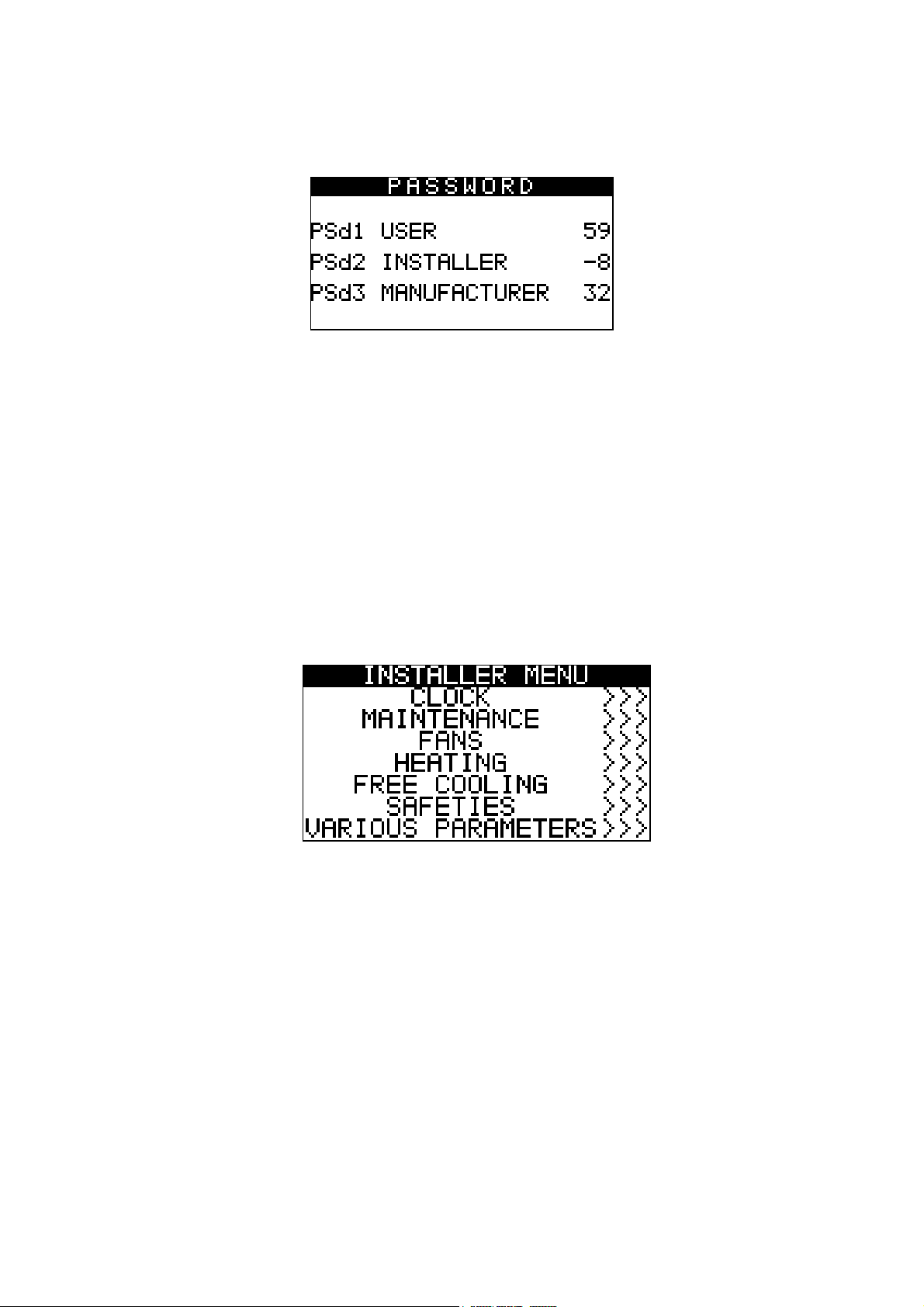
4.2.2 Password
Each menu has an associated level (except clock and log) with a relevant password for accessing to the various
functions present in that menu. Once the correct password has been entered the protected function can be accessed.
Two effects are obtained by entering a password correctly:
⋅ release of the correlated level
⋅ release of the sub-levels
page 21 of 68
Page 22
EVCO S.p.A. c-pro 3 micro SAVE/ c-pro 3 kilo SAVE | Application Manual ver. 1.0 | Code 144CP3UKSAE104
EVCO
Every level password can be modified from the same level or higher levels. For instance any password can be modified
from the manufacturer level.
The range of values accepted for the passwords is: -999 / 9999.
If no action is taken on a menu after 4 minutes the password inserted expires and it must be entered again.
4.2.3 User Menu
The User menu is on level 1, that is the level 1 (or higher) password must be taped in for entering the menu and
display/modify the parameters present in this branch.
By pushing the RIGHT key from this mask it is possible to access the page used for changing the password (PSd1).
4.2.4 Installer Menu
The Installer menu is on level 2, that is the level 2 (or higher) password must be taped in for entering the menu and
display/modify the parameters present in this branch.
The installer menu contains all parameters relevant for the configuration of all functionalities (alarms, regulation, logic,
features...) of the unit. Pushing the RIGHT or LEFT keys it is possible to access the mask for setting the password
(PSd2).
In the MAINTENANCE menu it is possible to view/enable the features relevant for the working condition of the devices
controlled (i.e. the running hours and the maximum threshold of hours acceptable). In this menu it is possible to see
the states of the physical inputs and outputs of the board and also to set the offset to be added to the analogue inputs
measure in order to compensate the readout error due to wiring, positioning of the probes.
In the FANS, HEATING and FREE COOLING menus it is possible to set the parameters for management of the related
devices
In the SAFETIES menu stand all parameters concerning the alarms and the management of the safety conditions for
the controlled devices
page 22 of 68
Page 23

EVCO S.p.A. c-pro 3 micro SAVE/ c-pro 3 kilo SAVE | Application Manual ver. 1.0 | Code 144CP3UKSAE104
EVCO
In the VARIOUS PARAMETERS menu stand other general parameters, moreover, entering this menu it is possible to
access the page for resetting the parameters to factory default values. In this menu you can change the user interface
language (PH32).
4.2.5 RTC Menu
This menu contains the functionalities linked to the system RTC:
⋅ the setting of the clock
⋅ setting the COMFORT/ECONOMY time bands
To enter this menu, press ENTER on the RTC mask from the main menu.
In this page it is possible to set the system clock and the two time periods of the fans’ automatic working (parameters
PT01 and PT02). By pushing the ESC key from this menu it is possible to go back to the general menu.
4.2.6 Manufacturer Menu
The Manufacturer menu is on level 3, that is the level 3 password must be taped in for entering the menu and
display/modify the parameters present in this branch. This menu can only be accessed with the unit OFF.
The manufacturer menu contains all parameters relevant to unit configuration.
In the CONFIGURATION menu it is possible to display/modify the parameters relevant for the design features of the
unit.
In the FANS, HEATING, OUTDOOR AIR DAMPER and RECOVERY HEAT EXCHANGER menus, it is possible to set the
parameters relevant to management of the devices.
In the SAFETIES menu stand all parameters concerning the alarms and the management of the safety conditions for
the controlled devices.
page 23 of 68
Page 24

EVCO S.p.A. c-pro 3 micro SAVE/ c-pro 3 kilo SAVE | Application Manual ver. 1.0 | Code 144CP3UKSAE104
EVCO
In the VARIOUS PARAMETERS menu stand other general parameters, moreover, entering this menu it is possible to
access the page for resetting the parameters to factory default values.
4.2.7 Main OFF page
The main OFF page changes depending on the reason why the unit is OFF. There are three possibilities:
1. Unit OFF: Unit switched-off pushing the relevant key
2. Unit OFF by Start-Stop: Unit ON by key but OFF due to digital contact DI/2 Start-Stop in “Stop” position
3. Unit OFF by Supervisor: Unit ON by key but OFF due to a Modbus command from the supervision module.
4. Unit OFF by Alarm: Unit switched-ON by key but switched-OFF due to unit block alarms.
Note: The MANUFACTURER menu can only be accessed if the unit is in one of these states.
page 24 of 68
Page 25

EVCO S.p.A. c-pro 3 micro SAVE/ c-pro 3 kilo SAVE | Application Manual ver. 1.0 | Code 144CP3UKSAE104
Fans speed
control.
EVCO
4.2.8 Main ON page
The main page is displayed when the unit is in ON mode:
COMPACT VERSION
Recovery Heat Exchanger Bypass
Information regarding the fans working
mode:
Alarm icon: appears when there
are active alarms. If all of them
have been viewed the icon
becomes fixed, otherwise (some active
- COMFORT: Comfort period automatic
control
- COMFORT+P.: Comfort period automatic
control WITH presence sensor active.
- ECONOMY: Economy period automatic
alarms not viewed) the icon keeps flashing.
From the main page it is possible to access the state pages by pressing the RIGHT key. Pressing ESC it’s possible to go
to the page for displaying the alarms and log.
COMPLETE VERSION
Air temperature set point for main
Information regarding the fans working
mode:
- COMFORT: Comfort period automatic
Alarm icon: appears when there
are active alarms. If all of them
have been viewed the icon
control
- COMFORT+P.: Comfort period automatic
control WITH presence sensor active.
- ECONOMY: Economy period automatic
becomes fixed, otherwise (some
active alarms not viewed) the icon keeps
flashing.
page 25 of 68
Page 26
EVCO S.p.A. c-pro 3 micro SAVE/ c-pro 3 kilo SAVE | Application Manual ver. 1.0 | Code 144CP3UKSAE104
EVCO
From the main page it is possible to access the state pages by pressing the RIGHT key. Pressing ESC it’s possible to go
to the page for displaying the alarms and log.
4.2.9 State Pages
From the main page it is possible to scroll the free access pages, which show the states of the controlled devices.
These pages are not protected by password and can only be accessed with unit ON. To display them, press the LEFT
and RIGHT keys.
Note: If some devices are disabled from parameter, the information regarding their working
status is replaced with dots “…” in order to avoid filling the state pages with information not
enabled by the control. The same is valid for the disabled probes.
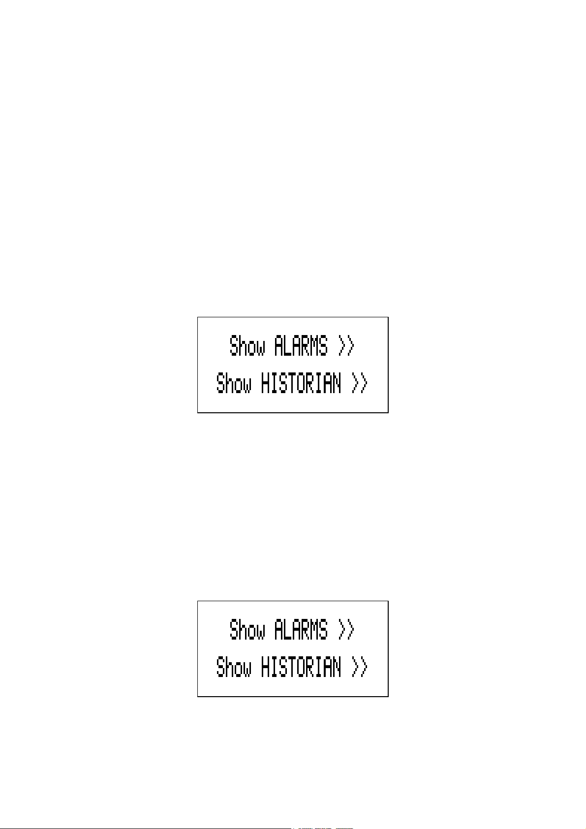
4.2.10 Alarm pages
To display the alarms, select “Show ALARMS>>>” from the general menu or press ESC from the main page to display
this page:
Position the cursor on “Show ALARMS >>” and then press ENTER key.
If no alarms are present the writing “NO ALARS” is displayed. Otherwise every time ENTER key is pushed the next
active alarm is displayed.
For resetting the alarm, in case the alarm condition is expired, keep pushed the ENTER key for about 2 seconds. If the
alarm cause is still active the alarm is not reset and the current mask remains displayed.
If the ESC key is pressed on an alarm page or you wait 60 seconds for timeout, go back to the main page of the
application. This level is not protected by a password.
4.2.11 Log pages
To display the alarms log, select HISTORIAN from the general menu or press ESC from the main page to display this
page:
move the cursor on “Show HISTORIAN >>” and push the ENTER key.
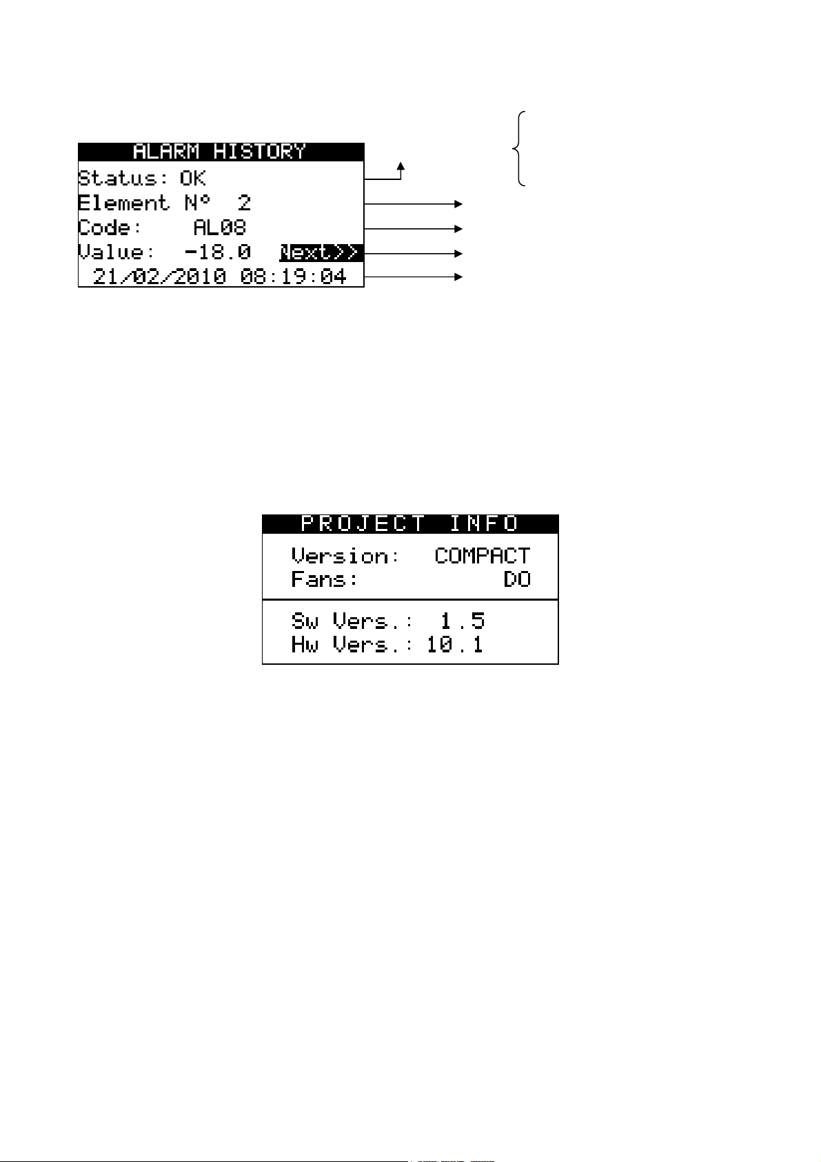
If no elements are present, “NO ALARMS” is displayed otherwise the following page is proposed:
page 26 of 68
Page 27
EVCO S.p.A. c-pro 3 micro SAVE/ c-pro 3 kilo SAVE | Application Manual ver. 1.0 | Code 144CP3UKSAE104
State of the log
Date and time of
Running number of the
Alarm code
Overflow: memory full
Alarm
value
EVCO
In this page stand the information regarding the last element in the log.
To view the previous element move the cursor on “Next>>” and push the ENTER key. By repeating this procedure it is
possible to scroll all log elements until reaching the first element inserted. Once reached the last element, on the
request of the next element, the last element memorised is re-proposed: log display is circular.
To exit the log pages, press the ESC key or wait 60 seconds for timeout. This level is not protected by a password.
Ok: correct reading
Empty: empty memory
4.2.12 Project and Firmware Versions
Press the LEFT+RIGHT keys at the same time for about 3 seconds. The information regarding the versions of the
project and the controller firmware are displayed.
To return to the main application page, press the ESC key.
page 27 of 68
Page 28

EVCO S.p.A. c-pro 3 micro SAVE/ c-pro 3 kilo SAVE | Application Manual ver. 1.0 | Code 144CP3UKSAE104
EVCO
5. Configuration parameters
Below are listed all parameters managed by the application. A brief description, the range of acceptable values, unit of
measurement, the default value proposed and the menu in which it is found is supplied for every parameter. The
menus are structured following this logic:
⋅ UT: user menu
⋅ IS: installer menu
o OR: Clock branch installer menu
o IS-MA: maintenance branch installer menu
o IS-F: fans branch installer menu
o IS-B: heating coils branch installer menu
o IS-SE: outside air damper branch installer menu
o IS-FC: Free Cooling branch installer menu
o IS-S: safety device branch installer menu
o IS-V: various parameters branch installer menu
o IS-D: default branch installer menu
⋅ C O: manufacturer menu
o CO-G Configuration branch manufacturer menu
o CO-F Fans branch manufacturer menu
o CO-B Heating coils branch manufacturer menu
o CO-SE Outside air damper branch manufacturer menu (free-cooling)
o CO-RH Recovery heat exchanger branch manufacturer menu
o CO-S Safety branch manufacturer menu
o CO-V Various branch manufacturer menu
5.1 COMPACT solution list of configuration parameters
Code Parameter description Default Min Max UM Menu Notes
Level 1 USER MENU
USER
Only if
PF02
PSd1 User level password (1) 0 -999 9999 - UT
Level 2 INSTALLER MENU
PT01 Start of the COMFORT time period 08:00:00 00:00:00 23:59:59 - OR
PT02 Start of the ECONOMY time period 20:00:00 00:00:00 23:59:59 - OR
PT11 Sunday
PT12 Monday
PT13 Tuesday
Fans speed/Capacity in manual regulation
mode
CLOCK
V3 V0 V3 UT
0
Working 0 Working 1 Not Working
0
Working 0 Working 1 Not Working
0
Working 0 Working 1 Not Working
OR
OR
OR
PF01=0
(Manual
Regulation)
page 28 of 68
Page 29

EVCO S.p.A. c-pro 3 micro SAVE/ c-pro 3 kilo SAVE | Application Manual ver. 1.0 | Code 144CP3UKSAE104
EVCO
PT14 Wednesday
PT15 Thursday
PT16 Friday
PT17 Saturday
0
Working 0 Working 1 Not Working
0
Working 0 Working 1 Not Working
0
Working 0 Working 1 Not Working
0
Working 0 Working 1 Not Working
OR
OR
OR
OR
Code Parameter description Default Min Max UM Menu Notes
MAINTENANCE
PM01
PM02
PM03
PM90
PM11
Max number of fans working hours.
The relevant alarm occurs over this limit
Supply fan
working hours
Return fan
working hours
Last maintenance
date
Anti-freeze air temperature
probe offset
8000 0 100000 Hours IS-MA
0 0 100000 Hours IS-MA
0 0 100000 Hours IS-MA
IS-MA
0.0
-10.0
-18.0
10.0
18.0
°C
°F
IS-MA
FANS
Type of fans control:
PF00
0: Speed
0 0 1 IS-F
1: Capacity
Type of fans regulation:
0: Manual
PF01
1: Automatic
0 0 3 IS-F
2: Automatic with presence sensor
3: Automatic with CO2 probe
PF03
PF04
Speed/Capacity fans in
COMFORT period
Speed/Capacity fans in
ECONOMY period
V2 V1 V3 IS-F
V1 V0 V2 IS-F
PF05 Speed/Capacity fans in RTC error V0 V0 V3 IS-F
PF12
PF13
PF21
PF23
Speed/Capacity fans in COMFORT with
presence sensor active
Speed/Capacity in case of
« non Working » day
Speed variator value corresponding
to speed V1
Speed variator value corresponding
to speed V2
Speed variator value corresponding
to speed V3
V3 V1 V3 IS-F
V0 V0 V3 IS-F
33.50 0.00 100.00 % IS-F
66.50 0.00 100.00 % IS-F
100.00 0.00 100.00 % IS-F
page 29 of 68
Only if
PF01=1/2/3
PF22
Page 30

EVCO S.p.A. c-pro 3 micro SAVE/ c-pro 3 kilo SAVE | Application Manual ver. 1.0 | Code 144CP3UKSAE104
EVCO
PF30
PF31
PF32
Minima velocità per la regolazione
modulante dei ventilatori
Massima velocità per la regolazione modulante
dei ventilatori
Setpoint rampa di regolazione pressione
statica
0.0 0.0 PF31 % IS-F
100.0 PF30 100.0 % IS-F
300 0 30000
Pa/
min
IS-F
PF33 Setpoint V1 regolazione pressione statica 300 0 30000 Pa IS-F
PF34 Setpoint V2 regolazione pressione statica 400 0 30000 Pa IS-F
PF35 Setpoint V3 regolazione pressione statica 500 0 30000 Pa IS-F
PF36 Setpoint regolazione banda proporzionale 200 0 10000 Pa IS-F
PF37
PF38
Tempo integrale regolazione pressione
statica
Velocità per la regolazione pressostatica in
errore sonda
0 0 300 Sec IS-F
30.0 0.0 100.0 % IS-F
ALARM PARAMETERS
PA01
PA02
PA04
PA25
PA27
Enabling fans working
hours alarm
Signals working hours alarms
on alarm relay
Signals the supply/return fans thermal
overload on the alarm relay
Signals RTC alarm
on alarm relay
Signals probe alarms
on alarm relay
Active
(1)
Not-active
(0)
Active (1) - IS-S
No (0) No (0) Yes (1) - IS-S
Yes (1) No (0) Yes (1) - IS-S
Yes (1) No (0) Yes (1) - IS-S
Yes (1) No (0) Yes (1) - IS-S
VARIOUS PARAMETERS
PH01 Minimum temperature value -15.0
-20.0
-4.0
PH02 Maximum temperature value 95.0 PH01
PH05
PH06
Enables unit switch-on/off from
"Start/Stop" digital input
Enables unit switch-on/off from
supervisor
Yes (1) No (0) Yes (1) - IS-V
No (0) No (0) Yes (1) IS-V
PH02
110.0
230.0
°C
°F
°C
°F
IS-V
IS-V
Set Yes (1)
ad wait for
PH18 Cancels the alarms log NO (0) NO (0) YES (1) - IS-V
the NO (0)
value to be
read again
PH20 Enable buzzer Yes (1) No (0) Yes (1) - IS-V
Temperature unit of measurement
PH30
0: °Celsius
0 (°C) 0 (°C) 1 (°F) - IS-V
1: °Fahrenheit
Code Parameter description Default Min Max UM Menu Notes
Language
PH32
of user interface
ENG ENG FRE - IS-V
(English, Italian, French)
page 30 of 68
Page 31
EVCO S.p.A. c-pro 3 micro SAVE/ c-pro 3 kilo SAVE | Application Manual ver. 1.0 | Code 144CP3UKSAE104
EVCO
Wait for the
NO (0)
PH99 Reset the factory parameters default NO (0) NO (0) YES (1) - IS-D
value to be
read again
on reset
completion
PSd2 Installer level password (2) 0 -999 9999 - IS
Level 3 MANUFACTURER MENU
After modification of these parameters it is recommended to remove and then re-apply the power supply to the board.
CONFIGURATION PARAMETERS
Unit type:
PG00
1=Compact
1 1 2 - CO-G
2=Complete
PG01 Enabling bypass recuperator Yes (1) No (0) Yes (1) - CO-G
Selection of type of device
for heating:
PG02
0: Disabled
1: Hot water coil only
Disabled
(0)
Disabled
(0)
Heaters
(3)
- CO-G
2: Electric heater coil only DO
3: Electric heater coil only AO
Type of recovery heat exchanger by-pass
PG03
damper control:
0: Digital Control (DO7)
AO (1) DO (0) AO (1) - CO-G
1: Analogue Control (AO3)
PG04 Outside air damper enabling No (0) No (0) Yes (1) - CO-G
PG05 Enabling of post-ventilation No (0) No (0) Yes (1) - CO-G
PG06
PG08
Enabling of recovery heat exchanger anti-
freeze protection
Enabling of recovery heat exchanger
by-pass in summer
Type 1
(1)
Not-active
(0)
Type 2 (2) - CO-G
No (0) No (0) Yes (1) CO-G
PG09 Activation of outside air damper limit switch No (0) No (0) Yes (1) CO-G
PG10 Type of fan DO (0) DO (0) AO (1) - CO-G
If PF=1
PG10=1
PG11 Enabling of mixing room damper No (0) No (0) Yes (1) - CO-G
PSd1 User level password (1) 0 -999 9999 - CO-G
PSd2 Installer level password (2) 0 -999 9999 - CO-G
PSd3 Manufacturer level password (3) 0 -999 9999 - CO-G
FANS
PF06
PF07
PF08
PF09
Minimum time that must pass for the switch-
on/off of each individual step of the fans
Temperature setpoint of the fans for anti-
freeze protection of the recovery heat
exchanger
Differential for anti-freeze protection of
the recovery heat exchanger
Minimum stand-by time before requesting
switch-off of a further fan step
3 0 999 Sec CO-F
2.0 PH01 PH02
2.0
0.0
0.0
20.0
36.0
°C
°F
°C
°F
CO-F
CO-F
5 1 99 Min CO-F
page 31 of 68
Page 32

EVCO S.p.A. c-pro 3 micro SAVE/ c-pro 3 kilo SAVE | Application Manual ver. 1.0 | Code 144CP3UKSAE104
EVCO
PF10
PF11
PS01
PS02
Differential for the by-pass of the recovery
unit damper in anti-freeze protection
mode
Fans working time in post-ventilation
mode
OUTSIDE AIR DAMPER
This menu is only accessible if PG04=1
Fans switch-on delay from outside air
damper activation
Outside air damper switch-OFF delay from
fans switch-off
2.0 0.0
30 0 999 Sec CO-F
45 0 999 Sec CO-SE
15 0 999 Sec CO-SE
20.0
36.0
°C
°F
CO-F
Reading
only
PS05 Delay of outside air damper end run 60 0 999 Sec CO-SE
Enable FreeHeating
PS06
0: No
No (0) No (0) Yes (1) CO-SE
1: Yes
Type damper control mixing room
0: Free-Heating only
PS07
1: Regulating air quality only
2: Priorities on demand higher of the two
0 0 4 CO-SE
3: Average of the two requests
4: Fixed open
PS08
PS09
Minimum aperture shutter
mixing room
Maximum aperture shutter mixing
chamber
20.0 0.0 PS09 % CO-SE
100.0 PS08 100.0 % CO-SE
PS10 Fixed value of damper opening 50.0 0.0 100.0 % CO-SE
PS12
PS13
Differential which enables free-cooling
and free-heating temperature
Setpoint differential which enables free-
cooling and free-heating temperature
2.0 0.0 20.0 °C CO-SE
4.0 0.0 20.0 °C CO-SE
Opening the minimum and maximum
damper
PS15
0:
Disabled
2 0 2 CO-SE
1: Only internal bandwidth
2: Always
PS20 Setpoint - adjusting the air quality 600 0 10000 ppm CO-SE
PS21 Differential - adjusting the air quality 100 0 2000 ppm CO-SE
RECOVERY HEAT EXCHANGER
Pr01
Pr02
Pr03
Anti-freeze temperature minimum
setpoint
Anti-freeze temperature minimum
differential
Recovery heat exchanger by-pass cycle
time for cyclical defrosting
1.0 PH01 PH02
2.0
0.0
0.0
20.0
36.0
5 1 99 Min CO-RH
°C
°F
°C
°F
CO-RH
CO-RH
Used only if
PG06 = 2
ALARM PARAMETERS
PA03
Enabling of supply/return fans thermal
overload alarm
Active
(1)
Not-active
(0)
Active (1) - CO-S
page 32 of 68
Page 33

EVCO S.p.A. c-pro 3 micro SAVE/ c-pro 3 kilo SAVE | Application Manual ver. 1.0 | Code 144CP3UKSAE104
EVCO
Not-
active
(0)
Not-active
(0)
Active (1) Sec CO-S
PA05
Enabling of differential pressure switch
alarm
PA06 Delay of differential pressure switch alarm 10 0 999 Sec CO-S
PA08
Signals differential pressure switch alarm
on alarm relay
PA09 Anti-freeze alarm active on hot water coil
No (0) No (0) Yes (1) Sec CO-S
Not-
active
(0)
Not-active
(0)
Active (1) Sec CO-S
Only if
PG02=0
PA10 Anti-freeze alarm delay on hot water coil 10 0 999 Sec CO-S
Not-
PA12 Activates the heaters thermal switch alarm
active
(0)
PA13
PA16
Signals heaters thermal overload alarm on
alarm relay
Enable supply high temperature alarm
from transducer
No (0) No (0) Yes (1) CO-S
Not-
active
(0)
PA17 Supply high temperature alarm setpoint 85.0 PH01 PH02
PA19
Supply high/low temperature alarms
differential
3.0
Not-active
(0)
Not-active
(0)
0.0
0.0
Active (1) Sec CO-S
Active (1) CO-S
20.0
36.0
°C
°F
°C
°F
CO-S
CO-S
Only if
PG02>=2
Only if
PG02=2
PA20 High/low temperature alarms delay 10 0 999 Sec CO-S
PA22 Expansion alarm delay 5 0 999 Sec CO-S
PA24 RTC alarm enabling
Active
(1)
Not-active
(0)
Active (1) - CO-S
PA26 Probes alarms signals delay 10 0 240 Sec CO-S
Type of alarm fire/smoke
0: Not-active
PA51
1: Off by allarm
1 0 3 - CO-S
2: Forcing 1
3: Forcing 2
VARIOUS PARAMETERS
PH11 Board Modbus address 1 1 247 - CO-V
Communication Baud Rate for the board
PH12
(0=1200, 1=2400, 2=4800, 3=9600,
3 0 4 - CO-V
4=19200)
PH13 ModBus Parity (0=none, 1=Odd, 2=Even) 2 0 2 - CO-V
PH14 Stop Bit ModBus (0=1bit, 1=2bit) 0 0 1 - CO-V
PH40 Enable supply temperature probe No (01) No (0) Yes (1) - CO-V
PH41 Enable return temperature probe No (0) No (0) Yes (1) - CO-V
PH42 Enable CO2 probe (0-5V) No (0) No (0) Yes (1) - CO-V
PH43 Enable outside air temperature probe No (0) No (0) Yes (1) - CO-V
PH44
CO2 sensor probe
0: 0-20mA
1: 4-20mA
2: 0-5V
0-10V
(3)
0-20mA
(3)
0-10V (3) - CO-V
page 33 of 68
Page 34

EVCO S.p.A. c-pro 3 micro SAVE/ c-pro 3 kilo SAVE | Application Manual ver. 1.0 | Code 144CP3UKSAE104
EVCO
3: 0-10V
PH51 Logic of the digital input DI1 N.O. (0) N.O. (0) N.C. (1) - CO-V
PH52 Logic of the digital input DI2 N.O. (0) N.O. (0) N.C. (1) - CO-V
PH53 Logic of the digital input DI3 N.C. (1) N.O. (0) N.C. (1) - CO-V
PH54 Logic of the digital input DI4 N.C. (1) N.O. (0) N.C. (1) - CO-V
PH56 Logic of the digital input DI5 N.C. (1) N.O. (0) N.C. (1) - CO-V
PH57 Logic of the digital input DI6 N.O. (0) N.O. (0) N.C. (1) - CO-V
PH58 Logic of the digital input DI7 N.C. (1) N.O. (0) N.C. (1) - CO-V
PH59 Logic of the digital input DI8 N.O. (0) N.O. (0) N.C. (1) - CO-V
PH60 Logic of the alarm relay DI9 N.O. (0) N.O. (0) N.C. (1) - CO-V
PH61 Logic of the alarm relay DO12 N.O. (0) N.O. (0) N.C. (1) - CO-V
PH80
CAN communication Baud Rate
(20K, 50K, 125K, 500K)
1 1 4 - CO-V
Note: Once the unit parameters have been configured and at each modification of the configuration parameters it is
recommended to switch OFF / switch ON the power supply to the board to make sure the configuration has been
correctly updated.
5.2 COMPLETE solution list of configuration parameters
Code Parameter description Default Min Max UM Menu Notes
Level 1 USER MENU
USER
SPHM Supply temperature heating setpoint 22.0 PH01 PH02
SPHR Return temperature heating setpoint 20.0 PH01 PH02
PF02
Speed/Capacity fans in manual regulation
mode
V3 V0 V3 UT
PSd1 User level password (1) 0 -999 9999 - UT
Level 2 INSTALLER MENU
CLOCK
PT01 Start of the COMFORT time period 8:00:00 00:00:00 23:59:59 - OR
PT02 Start of the ECONOMY time period 20:00:00 00:00:00 23:59:59 - OR
PT11 Sunday
PT12 Monday
PT13 Tuesday
PT14 Wednesday
PT15 Thursday
0
Working 0 Working 1 Not Working
0
Working 0 Working 1 Not Working
0
Working 0 Working 1 Not Working
0
Working 0 Working 1 Not Working
0
Working 0 Working 1 Not Working
PT16 Friday 0 0 1 OR
°C
°F
°C
°F
UT
UT
OR
OR
OR
OR
OR
Only if
PF01=0
(Manual
Regulation)
page 34 of 68
Page 35

EVCO S.p.A. c-pro 3 micro SAVE/ c-pro 3 kilo SAVE | Application Manual ver. 1.0 | Code 144CP3UKSAE104
EVCO
Working Working Not Working
PT17 Saturday
0
Working 0 Working 1 Not Working
OR
MAINTENANCE
Functioning hours maximum limit for fans.
PM01
The relevant alarm will be triggered over
8000 0 100000 Hours IS-MA
this limit
PM02 Outlet fan functioning hours 0 0 100000 Hours IS-MA
PM03 Return fan functioning hours 0 0 100000 Hours IS-MA
PM90
PM11
PM12
PM13
Last date on which maintenance was
performed on the machine
Calibration of the anti-freeze air
temperature probe
Calibration of the outlet air temperature
probe
Calibration of the return air temperature
probe
IS-MA
0.0
0.0
0.0
-10.0
-18.0
-10.0
-18.0
-10.0
-18.0
10.0
18.0
10.0
18.0
10.0
18.0
°C
°F
°C
°F
°C
°F
IS-MA
IS-MA
IS-MA
PM14 Calibration of the CO2 probe 0.0 -200 200 ppm IS-MA
PM15
Calibration of the outside air introduction
temperature probe
0.0
-10.0
-18.0
10.0
18.0
°C
°F
IS-MA
PM16 Calibration of the pressure probe 1 0.0 -200 200 ppm IS-MA
PM17 Calibration of the pressure probe 2 0.0 -2000 2000 Pa IS-MA
FANS
Type of fans control:
PF00
0: Speed
0 0 1 - IS-F
1: Capacity
Type of fans regulation:
0: Manual
PF01
1: Automatic
0 0 3 - IS-F
2: Automatic with presence sensor
3: Automatic with CO2 sensor
PF03 Fans Speed/Capacity in COMFORT period V2 V1 V3 - IS-F
PF04 Fans Speed/Capacity in ECONOMY period V1 V0 V2 - IS-F
PF05 Fans Speed/Capacity in RTC error V0 V0 V3 - IS-F
PF12
PF13
Fans Speed/Capacity in COMFORT with
presence sensor active
Speed/Capacity in case of « non working »
day
V3 V1 V3 - IS-F
V0 V0 V3 - IS-F
PF14 Set point CO2 probe 500 PH03 PH04 ppm IS-F
PF15 Proportional band CO2 probe 600 0 1000 ppm IS-F
PF16 Type of CO2 regulation 0 0 1 IS-F
PF17 Integral time CO2 regulation 0 0 300 sec IS-F
PF21 Speed variator value corresponding to speed V1 33.50 0.00 100.00 % IS-F
Only if
PF01=1/2/3
If PF00=1
PF16=1
page 35 of 68
Page 36

EVCO S.p.A. c-pro 3 micro SAVE/ c-pro 3 kilo SAVE | Application Manual ver. 1.0 | Code 144CP3UKSAE104
EVCO
PF22 Speed variator value corresponding to speed V2 66.50 0.00 100.00 % IS-F
PF23 Speed variator value corresponding to speed V3 100.00 0.00 100.00 % IS-F
PF30 Minimum speed for modulating fan 0.0 0.0 PF31 % IS-F
PF31 Maximum speed for modulating fan 100.0 PF30 100.0 % IS-F
PF32 Static pressure setpoint ramp adjustment 300 0 30000 Pa/min IS-F
PF33 V1 static pressure setpoint adjustment 300 0 30000 Pa IS-F
PF34 V2 static pressure setpoint adjustment 400 0 30000 Pa IS-F
PF35 V3 static pressure setpoint adjustment 500 0 30000 Pa IS-F
PF36 Setpoint adjustment proportional band 200 0 10000 Pa IS-F
PF37 Integral time setting static pressure 0 0 300 Sec IS-F
PF38
Speed controller for pressure switch in
probe error
HEATING COILS
This menu is only accessible if PG02>0
30.0 0.0 100.0 % IS-F
Regulation probe for heating
Pb01
0: Supply Probe
0 0 1 IS-B
1: Return Probe
FREECOOLING
Pr04
Pr05
Outside air/recovery heat exchanger by-
pass temperature set point in summer
Return air/recovery heat exchanger by-
pass temperature set point in summer
15.0 PH01 PH02
22.0 PH01 PH02
°C
°F
°C
°F
IS-FC
IS-FC
ALARM PARAMETERS
Not-
PA01 Enabling fans working hours alarm Active (1)
active
Active (1) - IS-S
(0)
PA02
PA04
PA07
PA11
PA15
PA21
Signals working hours alarms on alarm
relay
Signals the supply/return fans thermal
overload alarm on the alarm relay
Differential pressure switch alarm delay on
unit start-up
Signals the coil anti-freeze alarm on the
alarm relay
Signalling of the outside air damper limit
switch alarm on alarm relay
Signalling of high/low temperature alarms
on the alarm relay
No (0) No (0) Yes (1) - IS-S
Yes (1) No (0) Yes (1) - IS-S
60 0 999 sec IS-S
Yes (1) No (0) Yes (1) - IS-S
Yes (1) No (0) Yes (1) - IS-S
yes (1) No (0) Yes (1) - IS-S
PA23 Signalling fire/smoke on alarm relay Yes (1) No (0) Yes (1) - IS-S
PA25 Signals RTC alarm on alarm relay Yes (1) No (0) Yes (1) - IS-S
PA27 Signals probe alarms on alarm relay Yes (1) No (0) Yes (1) - IS-S
VARIOUS PARAMETERS
PH01 Minimum temperature value -15.0
-20.0
-4.0
PH02 Maximum temperature value 95.0 PH01
PH02
110.0
230.0
°C
°F
°C
°F
IS-V
IS-V
PH03 Minimum CO2 probe PPM value 0 0 PH04 ppm IS-V
Only if
PG02=1
page 36 of 68
Page 37

EVCO S.p.A. c-pro 3 micro SAVE/ c-pro 3 kilo SAVE | Application Manual ver. 1.0 | Code 144CP3UKSAE104
EVCO
PH04 Maximum CO
PH05
Enables unit switch-on/off from
“Start/Stop” digital input
probe PPM value 1100 PH03 10000 ppm IS-V
2
Yes (1) No (0) Yes (1) - IS-V
PH06 Enables unit switch-on/off from supervisor No (0) No (0) Yes (1) - IS-V
PH07 Minimum value Pa pressure probe 0 0 32000 Pa IS-V
PH08 Maximum value Pa pressure probe 3000 0 32000 Pa IS-V
Set YES (1)
PH18 Clear hystorical alarms NO (0) NO (0) YES (1) - IS-V
ad wait for
the NO (0)
PH20 Enable buzzer Yes (1) No (0) Yes (1) - IS-V
Temperature unit of measurement
PH30
0: °Celsius
0 (°C) 0 (°C) 1 (°F) - IS-V
1: °Fahrenheit
PH32
Language of user interface
(English, Italian, French)
ENG ENG FRE - IS-V
Wait for the
NO (0)
PH99 Reset the factory parameters default NO (0) NO (0) YES (1) - IS-D
value to be
read again
on reset
completion
PSd2 Installer level password (2) 0 -999 9999 - IS
Level 3 MANUFACTURER MENU
After modification of these parameters it is recommended to remove and then re-apply the power supply to the board.
CONFIGURATION PARAMETERS
Unit type:
PG00
1=Compact
2 1 2 - CO-G
2=Complete
PG01 Enabling bypass recuperation Yes (1) No (0) Yes (1) - CO-G
Selection of type of device for heating:
0: Disabled
PG02
1: Hot water coil only
3 0 3 - CO-G
2: Electric heater DO coil only
3: Electric heater AO coil only
Type of recovery heat exchanger by-pass
PG03
damper control:
0: Digital Control (DO7)
DO (0) DO (0) AO (1) - CO-G
1: Analogue Control (AO3)
PG04 Outside air damper enabling Yes (1) No (0) Yes (1) - CO-G
PG05 Enabling of post-ventilation Yes (1) No (0) Yes (1) - CO-G
PG06
PG08
Enabling of recovery heat exchanger anti-
freeze protection
Enabling of recovery heat exchanger by-pass
in summer
Type 1
(1)
Disabled
(0)
Type 2 (2) - CO-G
Yes (1) No (0) Yes (1) CO-G
PG09 Activation of outside air damper end run Yes (1) No (0) Yes (1) CO-G
PG10 Type of fan DO (0) DO (0) AO (1) - CO-G
If PF00=1
PG10=1
page 37 of 68
Page 38

EVCO S.p.A. c-pro 3 micro SAVE/ c-pro 3 kilo SAVE | Application Manual ver. 1.0 | Code 144CP3UKSAE104
EVCO
PSd1 User level password (1) 0 -999 9999 - CO-G
PSd2 Installer level password (2) 0 -999 9999 - CO-G
PSd3 Manufacturer level password (3) 0 -999 9999 - CO-G
FANS
PF06
PF07
PF08
PF09
PF10
PF11
Pb02
Pb03
Pb04
Pb05
Pb06
Minimum time that must pass for the switch-
on/off of each individual step of the fans
Fans temperature setpoint for anti-freeze
protection of the recovery heat exchanger
Fans differential for anti-freeze protection of
the recovery heat exchanger
Minimum stand-by time before requesting
switch-off of a further fan step
Fans differential regulation for the by-pass of
the recovery unit damper in anti-freeze
protection mode
Fans functioning time in post-ventilation
mode
HEATING COILS
This menu is only accessible if PG02>0
Proportional band for PI regulation of the
heating coil (water/electric)
Integral time for PI regulation of the heating
coil (water/electric)
Hot water coil opening value in regulation
probe error mode
Heaters single stage insertion/release time
for post-heating
Number of electric heaters active during
probe error mode.
3 0 999 Sec CO-F
2.0 PH01 PH02
2.0
0.0
0.0
20.0
36.0
°C
°F
°C
°F
CO-F
CO-F
5 1 99 Min CO-F
2.0
0.0
0.0
20.0
36.0
°C
°F
CO-F
30 0 999 Sec CO-F
10.0
0.0
0.0
20.0
36.0
°C
°F
CO-B
0 0 999 Sec CO-B
0.0 0.0 100.0 % CO-B
60 0 999 Sec CO-B
1 0 3 CO-B
If Pb03=0
integral action
not present
Pb07 Time PWM electric heaters 2 0 20 Sec CO-B
OUTSIDE AIR DAMPER
This menu is only accessible if PG04=1
PS01
PS02
Fans switch-on delay from outside air damper
activation
Outside air damper switch-on delay from fans
switch-off
45 0 999 Sec CO-SE
15 0 999 Sec CO-SE
PS05 Delay of outside air damper end run 60 0 999 Sec CO-SE
FreeHeating enabling
PS06
0: No
No (0) No (0) Si (1) CO-SE
1: Yes
Type damper control mixing room
0: Only for Free-heating
PS07
1: Only for regulating air quality
2: Priorities on demand higher of the two
0 0 4 CO-SE
3: Average of the two requests
4: Fixed aperture
page 38 of 68
Page 39

EVCO S.p.A. c-pro 3 micro SAVE/ c-pro 3 kilo SAVE | Application Manual ver. 1.0 | Code 144CP3UKSAE104
EVCO
PS08 Minimum
opening damper mixing room 20.0 0.0 PS09 % CO-SE
PS09 Maximum opening damper mixing room 100.0 PS08 100.0 % CO-SE
PS10 Fixed value of damper open 50.0 0.0 100.0 % CO-SE
PS12
PS13
Differential which enables free-cooling and
free-heating temperature
Setpoint differential which enables free-
cooling and free-heating temperature
2.0 0.0 20.0
4.0 0.0 20.0
°C
°C
CO-SE
CO-SE
Minimum and maximum opening damper
PS15
0: Disabled
1: Only internal bandwidth
2 0 2 CO-SE
2: Always
PS20 Setpoint - Regulation the air quality 600 0 10000 ppm CO-SE
PS21 Differential - Regulation the air quality 100 0 2000 ppm CO-SE
RECOVERY HEAT EXCHANGER
Pr01 Anti-freeze temperature minimum setpoint 1.0 PH01 PH02
Pr02 Anti-freeze temperature minimum differential 2.0
Pr03
Recovery heat exchanger by-pass cycle time
for cyclical defrosting
5 1 99 Min CO-RH
0.0
0.0
20.0
36.0
°C
°F
°C
°F
CO-RH
CO-RH
ALARM PARAMETERS
PA03
Enabling of outlet/return fans thermal switch
alarm
Active (1)
PA05 Enabling of differential pressure switch alarm Active (1)
Not-
active
(0)
Not-
active
(0)
Active
(1)
Active
(1)
- CO-S
Sec CO-S
PA06 Delay of differential pressure switch alarm 10 0 999 Sec CO-S
PA08
PA09 Anti-freeze alarm active on hot water coil
Signals differential pressure switch alarm on
alarm relay
Yes (1) No (0) Yes (1) Sec CO-S Only if PG02=0
Not-
active (0)
Not-
active
(0)
Active
(1)
Sec CO-S
PA10 Anti-freeze alarm delay on hot water coil 10 0 999 Sec CO-S
Not-
PA12 Activates the heaters thermal overload alarm Active (1)
active
(0)
PA13
PA16
Signals heaters thermal switch alarm on
alarm relay
Enable supply high temperature alarm from
transducer
Yes (1) No (0) Yes (1) CO-S
Not-
Active (1)
active
(0)
PA17 Supply high temperature alarm setpoint 85.0 PH01 PH02
PA19
Supply high/low temperature alarms
differential
3.0
0.0
0.0
Active
(1)
Active
(1)
20.0
36.0
Sec CO-S
CO-S
°C
°F
°C
°F
CO-S
CO-S
PA20 High/low temperature alarms delay 10 0 999 Sec CO-S
page 39 of 68
Used only if
PG06=2
Only if
PG02>=2
Only if
PG02>=2
Page 40

EVCO S.p.A. c-pro 3 micro SAVE/ c-pro 3 kilo SAVE | Application Manual ver. 1.0 | Code 144CP3UKSAE104
EVCO
PA24 RTC alarm enabling Active (1)
Not-
active
(0)
Active
(1)
- CO-S
PA26 Probes alarms signals delay 10 0 240 Sec CO-S
Type of alarm fire/smoke
0: Not-active
PA51
1: Off by allarm
1 0 3 - CO-S
2: Forcing 1
3: Forcing 2
VARIOUS PARAMETERS
PH11 Board Modbus address 1 1 247 - CO-V
Communication Baud Rate for the board
PH12
(0=1200, 1=2400, 2=4800, 3=9600,
3 0 4 - CO-V
4=19200)
PH13 ModBus Parity (0=none, 1=Odd, 2=Even) 2 0 2 - CO-V
PH14 Stop Bit ModBus (0=1bit, 1=2bit) 0 0 1 - CO-V
PH40 Enable outlet temperature probe Yes (1) No (0) Yes (1) - CO-V
PH41 Enable return temperature probe Yes (1) No (0) Yes (1) - CO-V
PH42 Enable CO2 probe No (0) No (0) Yes (1) - CO-V
PH43 Enable outside air temperature probe Yes (1) No (0) Yes (1) - CO-V
Enable pressure probes
PH44
0: Not-active
1: probe 1
0 0 2 - CO-V
2: probe 2
CO2 sensor probe
PH45
0: 0-20mA
1: 4-20mA
2: 0-5V
0-10V (3)
0-20mA
(0)
0-10V
(3)
- CO-V
3: 0-10V
Pressure sensor probes
PH46
0: 0-20mA
1: 4-20mA
2: 0-5V
0-10V (3)
0-20mA
(0)
0-10V
(3)
- CO-V
3: 0-10V
PH47
Analog output-type electric heaters
0: 0-10V
1: PWM
0-10V (0)
0-10mA
(0)
PWM (1) - CO-V
PH51 Logic of the digital input DI1 N.O. (0) N.O. (0) N.C. (1) - CO-V
PH52 Logic of the digital input DI2 N.O. (0) N.O. (0) N.C. (1) - CO-V
PH53 Logic of the digital input DI3 N.C. (1) N.O. (0) N.C. (1) - CO-V
PH54 Logic of the digital input DI4 N.C. (1) N.O. (0) N.C. (1) - CO-V
PH56 Logic of the digital input DI5 N.C. (1) N.O. (0) N.C. (1) - CO-V
PH57 Logic of the digital input DI6 N.O. (0) N.O. (0) N.C. (1) - CO-V
PH58 Logic of the digital input DI7 N.C. (1) N.O. (0) N.C. (1) - CO-V
PH59 Logic of the digital input DI8 N.O. (0) N.O. (0) N.C. (1) - CO-V
PH60 Logic of the alarm relay DI9 N.O. (0) N.O. (0) N.C. (1) - CO-V
PH61 Logic of the alarm relay DO12 N.O. (0) N.O. (0) N.C. (1) - CO-V
page 40 of 68
Page 41

EVCO S.p.A. c-pro 3 micro SAVE/ c-pro 3 kilo SAVE | Application Manual ver. 1.0 | Code 144CP3UKSAE104
EVCO
PH80
CAN communication Baud Rate
(20K, 50K, 125K, 500K)
Notes: The outside air return probes activation parameters, respectively PH41 and PH43 are conditioned by the state
of PG01. If the input confirms the presence of the By-Pass, the two parameters are active, otherwise they are
deactivated. Any changes to the parameters are allowed, but any change in state of the digital input DI5 implies
changes of the two parameters.
Once the machine parameters have been configured and at every modification of the configuration parameters, it is
advised to remove and re-apply the power supply to the board to allow the control to configure itself correctly.
1 1 4 - CO-V
page 41 of 68
Page 42

EVCO S.p.A. c-pro 3 micro SAVE/ c-pro 3 kilo SAVE | Application Manual ver. 1.0 | Code 144CP3UKSAE104
EVCO
6. REGULATIONS
6.1 State of the unit
There are several unit switch-on/off procedures:
1) Via the relevant ON/OFF key
Switch-ON: press the relevant key for about 2 seconds, if all the conditions are fulfilled the unit starts working
(“ON” mode).
Switch-OFF: press the relevant key for about 2 seconds, the unit stops working (“OFF” mode).
2) Using the Start/Stop from digital input control (parameter, PH05=1)
Switch-ON: close the contact, if all the conditions are fulfilled the unit starts working (“ON” mode).
Switch-OFF: if the contact is open the unit stops working (“OFF from Start/Stop” mode).
3) Via Supervision protocol (parameter, PH06=1)
Switch-ON: activate the switch-on state from protocol, if all the conditions are fulfilled the unit starts working
(“ON” mode).
Switch-OFF: if deactivated by switch-on state protocol the unit stops working (“OFF from Supervisor” mode).
The ON/OFF status from key has priority with respect to the other two. In fact the ON/OFF states by digital input and
supervision protocol can only be reached with machine in “ON” mode.
A machine switched-off by Start/Stop digital input can:
⋅ pass to the OFF state from key (by pressing ESC).
⋅ pass to the OFF state from supervisor if the OFF condition from digital input returns and the OFF state is set
by supervisor.
⋅ ass to the ON state if the ON condition from digital input returns and the OFF state is not set by supervisor.
A unit switched-OFF by supervision protocol can:
⋅ Move to the OFF state by key (by pressing ESC key).
⋅ Move to the OFF state from digital input if the OFF condition from supervisor ceases and the OFF state from
digital input is triggered.
⋅ Move to the ON state if the OFF condition from supervisor ceases and the OFF state is not present from digital
input.
The unit ON/OFF key is the ESC key pressed for about 2 seconds.
The remote Start/Stop input (when present) can be configured using the parameters:
- PH05: Enables the function
- PH52: Sets the NC, NO logic for the digital contact
page 42 of 68
Page 43

EVCO S.p.A. c-pro 3 micro SAVE/ c-pro 3 kilo SAVE | Application Manual ver. 1.0 | Code 144CP3UKSAE104
EVCO
6.1.1 OFF state for alarm
When the machine is active and an heavy alarm occurs the unit switches into the OFF due to alarm status. In this
case the unit and all devices are switched OFF and the dampers are completely closed until the alarm condition has
been reset. When the unit is OFF for alarm it is possible to switch to the other OFF states by means of the relevant
digital input, key or supervisor.
The alarms that cause the “OFF for alarm” are:
- Supply fan thermal overload alarm
- Return fan thermal overload alarm
- Differential pressure switch alarm
- Outdoor air Damper limit switch alarm
The unit recovers the normal working mode when the alarm has been reset.
6.2 Unit Type
While the machine is turned off, using the parameter PG00 in the MANUFACTURER Menu, it is possibile to choose the
type of unit that you wish to utilize. Based on the value of the parameters, different defualts become available for the
configuration parameters. The regulation parameters can be modified manually according to user requirements.
Note. The default configurations can also be modified according to user requirements by entering modifications to the
paramaters manually.
ATTENTION. When changing the machine type (through modification of parameter PG00) it is necessary to shutdown
and then restart the card to ensure the unit has been correctly configured; in order to allow the card to assign all the
parameters contained therein it is advisable to wait a few seconds (3 seconds should be more than sufficient) before
removing the tension.
6.3 RTC setting
When the board is disconnected from the mains for many days the RTC (Real Time Clock) system clock backup battery
discharges. At the next connection to the mains the controller will display an RTC alarm. To get rid of it and allow a
proper working condition the RTC has to be updated using the below mask:
Once the clock is configured, press OK to update the RTC and access the main page of the application. Confirmation
by pressing OK also resets any clock alarm (AL16) as long as the alarm conditions are reset.
If the alarm should not disappear switch OFF and back ON power supply to the board and manually reset the alarm.
page 43 of 68
Page 44

EVCO S.p.A. c-pro 3 micro SAVE/ c-pro 3 kilo SAVE | Application Manual ver. 1.0 | Code 144CP3UKSAE104
EVCO
6.4 Restore the (factory) default parameters
Via the “Parameters Reset” procedure it is possible to bring back the system parameters to the default value. The
procedure can only be activated with machine in OFF mode
Enter the Installer ->Various Parameters -> Default menu and press the ENTER key.
Set the PH99 parameter to “YES”(1) and wait until it becomes “NO”(0) again on the display. The system automatically
restores all parameters’ default values.
Note: After this operation switch OFF and back ON power supply to the board to prevent for
malfunctioning.
6.5 Last maintenance operation date
From the Installer->Maintenance menu, press RIGHT until reaching the following mask:
Positioning the cursor on the “Update” writing and pushing the Enter key the old date relevant for the previous
maintenance will be overwritten with the present date updating the PM90 parameter.
page 44 of 68
Page 45

EVCO S.p.A. c-pro 3 micro SAVE/ c-pro 3 kilo SAVE | Application Manual ver. 1.0 | Code 144CP3UKSAE104
EVCO
6.6 Programming key
It is possible to save the value of all system parameters into the programming key or upload them from the
programming key. By means of this key is therefore possible also to copy the parameters from one device into one or
more compatible ones. The saving or uploading operation can be carried out only with machine OFF, by connecting the
key.
To save a parameter list in the programming key:
- Enter the DEFAULT menu
- Move the cursor on KEY Save: OK and push the ENTER key. The storage of the
parameters into the key will be done
To copy a parameter list from the programming key into the device:
- Enter the DEFAULT menu
- Move the cursor on KEY Upload: OK and push the ENTER key. The storage of the
parameters into the key will be done
-
Note: The information to the product and relevant software version are saved in the key in
order to allow the transfer of parameter maps only between compatible devices
page 45 of 68
Page 46

EVCO S.p.A. c-pro 3 micro SAVE/ c-pro 3 kilo SAVE | Application Manual ver. 1.0 | Code 144CP3UKSAE104
EVCO
6.7
This control solution offers the base functionality present also in the "complete" solution.
Functionality of the COMPACT control solution
6.7.1 Supply and return fans
The program manages two fans, supply and return. For the two fans is expected to ON / OFF control with three steps
or analog output. . The working is the same for both fan except for the case of Recovery heat exchanger antifreeze
protection and in function with two pressure probes.
The adjustment is based on the parameter distinct PF01, which distinguishes a manual adjustment with automatic and
automatic sensor signal is likely:
• PF01=0 manual regulation
• PF01=1 automatic regulation without presence sensor
• PF01=2 automatic regulation with presence sensor
• PF01=3 automatic regulation with CO2 sensor
La regolazione può controllare direttamente la velocità dei ventilatori (PF00=0), oppure controllare la portata dei
ventilatori (PF01=1).
If the speed is controlled all the configuration parameters will modify directly the speed of the fans
(PF02/PF03/PF04/PF05/PF12/PF13) with a choice V1/V2/V3. Instead in the case of flow control these parameters will
be to choose the setpoint adjustment V1/V2/V3 pressostativa (PF33/PF34/PF35).
In ON/OFF regulation (parameter PG10=0) the 3 speeds (V1, V2, V3) are activated each by a dedicated relay.
In regulation with speed variator inverter (parameter PG10=1) the three speeds are determined by the value defined
by the parameters PF21, PF22 and PF23, or it can run in the complete control of the ramp (see the sections on
Regulations).
6.7.1.1 Manual regulation
The fans work at the MANUAL Speed/capacity set via the PF02 parameter.
6.7.1.2 Automatic regulation without presence sensor
Two time periods are defined: ECONOMY time band and COMFORT time band. A working speed is defined for each
time period, respectively ECONOMY Speed/capacity (parameter PF04) and COMFORT Speed/capacity (parameter
PF03). The fans are controlled at the Speed/capacity defined in the relevant time periods. The following parameters
must be used
• PT01: start of COMFORT time band.
• PF03: fans Speed/capacity in COMFORT band.
• PT02: start of ECONOMY time band.
• PF04: fans Speed/capacity in ECONOMY band.
For each day of the week it is possible to define whether this day is a working or non-working day, parameters
PT11=Sunday, PT12, PT13, PT14, PT15, PT16, PT17):
- Working days: the regulation is the normal automatic type for ECONOMY e COMFORT time period;
- Non-working days: the Speed/capacity are determined by parameter PF13, due to defect V0.
Note: If the RTC system clock is in alarm condition it is possible to set the PF05 parameter to determine at which
speed both fans must function.
page 46 of 68
Page 47

EVCO S.p.A. c-pro 3 micro SAVE/ c-pro 3 kilo SAVE | Application Manual ver. 1.0 | Code 144CP3UKSAE104
EVCO
6.7.1.3 Automatic regulation with presence sensor
In addition to the previous regulation rules it is possible to modify the working Speed/capacity on the basis of a
presence sensor. If the presence sensor is active (indicating there is someone inside the room), during the COMFORT
time band the fans Speed/capacity is forced to the value set on parameter PF12.
6.7.1.4 Fans thermal overload
Via the digital inputs DI3/DI4 Supply/Return fans thermal overload protection it is possible to enable the thermal
overload alarm of each fan. The alarms are signalled after a fixed delay of 2 seconds and have automatic reset. The
alarms are enabled setting PA03=1. If this is not the case, the thermal overload alarms of the two fans are disabled.
The activation of the thermal overload alarm switches OFF the unit bringing it to the OFF due to alarm status.
6.7.1.5 Fans status
Each of the two fans can be in the following working states:
1. OFF: the fan is OFF.
2. ON V1: the fan is ON at speed 1.
3. ON V2: the fan is ON at speed 2.
4. ON V3: the fan is ON at speed 3.
5. Switch-ON stand-by: the fan is to be switched-on. Timing is in progress, e.g. stand-by due to pre-start of the
outside air damper. The status shows the switch-on stand-by for each of the individual speeds.
6. Switch-OFF stand-by: the fan is to be switched-off. Timing is in progress, e.g. in the case of post-ventilation.
7. Alarm: the fan is in alarm conditions due to thermal overload.
Reaching of the individual speed in switch-ON can be delayed via the parameter PF06. If PF06=0 switch-ON/OFF is
immediate.
6.7.1.6 Fans running hours
Each fan has an associated variable that counts the number of running hours (Supply fan parameter PM02, Return fan
parameter PM03). The running hours can be zeroed by resetting the relevant parameter.
If the running hours set in the PM01 parameter are exceeded, an alarm is given indicating fan running hours exceeded
(alarms AL09, AL10).
6.7.2 Recovery heat exchanger anti-freeze protection
A probe measures the temperature T of the exhaust air after the recovery heat exchanger on the extraction circuit.
The critical defrosting temperature Tg (can be set by parameter PF07) is fixed by default at 0 °C. Considering the risk
of frost in the recovery heat exchanger when T ≤ Tg it is necessary to take some action for protecting the exchanger
when this temperature level is reached. To use this function the PG06 parameter must be enabled (by default it is
always enabled).
There are two possible strategies depending on the presence of the by-pass damper of the recuperator (PG01
parameter).
Note: If the anti-freeze temperature probe is in error conditions, this regulation is not enabled and the fans are
regulated exclusively on the basis of the PF01 parameter.
page 47 of 68
Page 48

EVCO S.p.A. c-pro 3 micro SAVE/ c-pro 3 kilo SAVE | Application Manual ver. 1.0 | Code 144CP3UKSAE104
Tg -
OFF
Tg +
ON
r
Zone
Normal Working
EVCO
6.7.2.1 Unit without By-pass damper
In this case the action taken for anti-freeze purpose is decreasing the fan speeds with a neutral zone control.
When T ≤ Tg, the outlet fan speed will decrease progressively (V3-V2-V1) until stopping (V0). If this condition occurs
and remains for a time ∆t (time set by parameter PF09) the speed reduction takes place, every ∆t there is a further
decrease until the supply fan switches OFF.
If the temperature T is between Tg and Tg + Tdiff (default 3°C, can be modified by parameter PF08) the current speed
is maintained. Only when the temperature T becomes T ≥ Tg + Tdiff the fan speed returns to the normal condition
(i.e. at the speed set by the user).
Fan speed decrease
Neutral
Tg Tg + T. Anti-
6.7.2.2 Unit with motorised By-pass
Same behaviour as in the previous case with speed reduction but never down to zero in order to allow the air flow
through the recovery heat exchanger before being eject. As the exhaust air is warmer than the outside air the heat
exchanger is “defrosted”.
When the supply fan is at minimum speed and the low temperature situation still remains for ∆t minutes, the fan does
not switch off but there’s a particular activation strategy of the recovery heat exchanger By-Pass damper:
• When T ≤ Tg - TdiffByPass (default 2°C, can be modified by PF10 parameter): opening of the By-pass damper
• When T ≥ Tg + TdiffByPass: closure of the By-pass damper.
Dampe
T. Anti-
The return to normal working condition (speed selected by the user and By-Pass closed) takes place only when T ≥ Tg
+ Tdiff (default 2°C, can be modified by PF08 parameter).
The by-pass damper can be controlled using a digital signal or an analogue signal, it must be configured setting the
PG03 parameter from the manufacturer menu.
PG03=0
The damper is managed with a digital control via the DO7 relay. When the relay is not active the damper is closed
while when the relay is active the damper is open and the recovery heat exchanger is by-passed.
6.7.2.3 Recovery heat exchanger by-pass damper logic
page 48 of 68
Page 49

EVCO S.p.A. c-pro 3 micro SAVE/ c-pro 3 kilo SAVE | Application Manual ver. 1.0 | Code 144CP3UKSAE104
Pr01:
OFF
Pr02:
ON
T. Anti
-
freeze
OFF
ON
By-Pass damper
OFF
ON
Pr0
Pr0
T. Anti
-
EVCO
PG03=1
The damper is managed with an analogue control via the analogue output AO3. When 0% the damper is closed, while
when 100% the damper is open and the recovery heat exchanger is by-passed.
6.7.3 Cross flow recovery heat exchanger and by-pass
damper
The recovery heat exchanger to be used is the cross flow static type. The anti-freeze by-pass damper can be present
in the unit (optional PG01 parameter).
This damper allows the unit to work with very low outside air temperatures (e.g. –10 / -12°C) preventing the moisture
of the ejected air to condensate and freeze inside the heat exchanger (which would cause the obstruction of air flow up
to complete block).
The anti-freeze temperature probe identifies the freezing temperature and drives the fan speed decrease and the
activation of the recovery heat exchanger by-pass damper.
The recovery heat exchanger is normally active and is by-passed (opening the by-pass damper) only during free-
cooling (if present and enabled) and during cyclical defrosting when outside temperature is too low. To activate this
function set PG06 = 2
6.7.3.1 Cyclical defrosting with minimum temperatures
The set point must be determined along with its differential for the activation of the defrosting cycle.
When the anti-freeze minimum temperature condition is reached a cyclical by-pass sequence of the recovery heat
exchanger is activated to allow the exhaust air (warmer, from the room) to defrost the recovery heat exchanger air
channels as shown in the below diagram.
Exhaust air minimum
page 49 of 68
Page 50

EVCO S.p.A. c-pro 3 micro SAVE/ c-pro 3 kilo SAVE | Application Manual ver. 1.0 | Code 144CP3UKSAE104
Unit
ON
OFF
Air Flow
ON
ON
Alarm
PA0
PA0
PA0
EVCO
After the (parameter Pr03) delay the by-pass damper is activated to allow defrosting. As soon as the exhaust air
temperature is back above the accepted value the damper is deactivated and the recovery heat exchanger starts
again.
Note: If the anti-freeze probe is in alarm condition the function is disabled.
6.8 Features of the COMPLETE control solution
Al functions of the COMPACT version are included in this version.
Below are listed only the additional features of the COMPLETE control solution.
6.8.1 Post-Ventilation
By setting the parameter PG05=1 it is possible to decide whether to run the fans for a time configured on parameter
PF11, also after unit switch-OFF. If the function is active when the unit stops the fans keep working for further PF11
seconds.
6.8.2 Differential pressure switch
The lack of air flow is signalled via the DI5 Differential Pressure switch digital input. The pressure switch status is
considered after the initial start-up phase of the unit (the length of this phase is configured by parameter PA06). On
expiry of this time if the contact signals a lack of air flow the alarm is signalled immediately. During normal working
the differential pressure switch is monitored continuously. If the contact signals a lack of flow for a period exceeding
the PA06 parameter, the alarm is signalled immediately.
To enable the alarm, set PA05=1.
The differential pressure switch alarm has manual reset. Activation leads to switch-off of the unit taking it into the OFF
due to alarm status.
page 50 of 68
Page 51

EVCO S.p.A. c-pro 3 micro SAVE/ c-pro 3 kilo SAVE | Application Manual ver. 1.0 | Code 144CP3UKSAE104
T. esterna
– T. return
PS12:
EVCO
6.8.3 Fresh air intake damper
It is possible to manage an optional motorised damper (can be enabled by parameter PG04=1) for fresh air intake
purpose. The damper is managed via ON/OFF (digital) activation. The damper can be either fully open or fully closed,
modulation is not possible as well as a minimum opening.
When the fans are requested to start first the damper is opened and, after a delay configured on parameter PS01, the
fans are activated too.
When the fans are switched OFF the damper is kept open for a time configured on parameter PS02.
6.8.3.1 Fresh air intake damper limit switches
In order to have a feedback about the real status of the damper (fully open or fully closed) the digital inputs DI9 and
DI10 are connected to the damper’s “fully open” and “fully closed” limit switches. Every time the damper is requested
to change its status it is verified that both limit switches change their status within the expected time frame (defined
on parameter PS05). If during this time the states of both digital inputs change this means everything is working fine.
If this is not the case the AL06 alarm with manual reset is generated and the unit is brought to the “OFF due to alarm”
status.
6.8.4 Damper mixing room
La serranda viene regolata in base al parametro PS074, e può essere utilizzata per:
- Free-Heating
- Air quality control
- The larger of the 2 requests
- The average of the 3 required
- A fixed value
The adjustment also provides a minimum opening position of the damper to ensure the design minimum quantity
of fresh air (parameter PS08) and the corresponding position of maximum opening (parameter PS09).
If the setting is fixed aperture in the louvre is always the same aperture value decided by the parameter PS10.
If the adjustment is freeHeating, is activated when the temperature difference between the outside air and the
return air temperature reaches the setpoint (parameter PS13) and the response threshold (parameter PS12).
When there are conditions of free-heating, or is there a license to regulation (and the demand is greater than zero)
that controls the ramp heating is split into two flights later, the first one (about half the switching differential) adjusts
the free-heating by means of the damper, the second rule the users in charge of the heating.
PS13:SetFH
page 51 of 68
Page 52
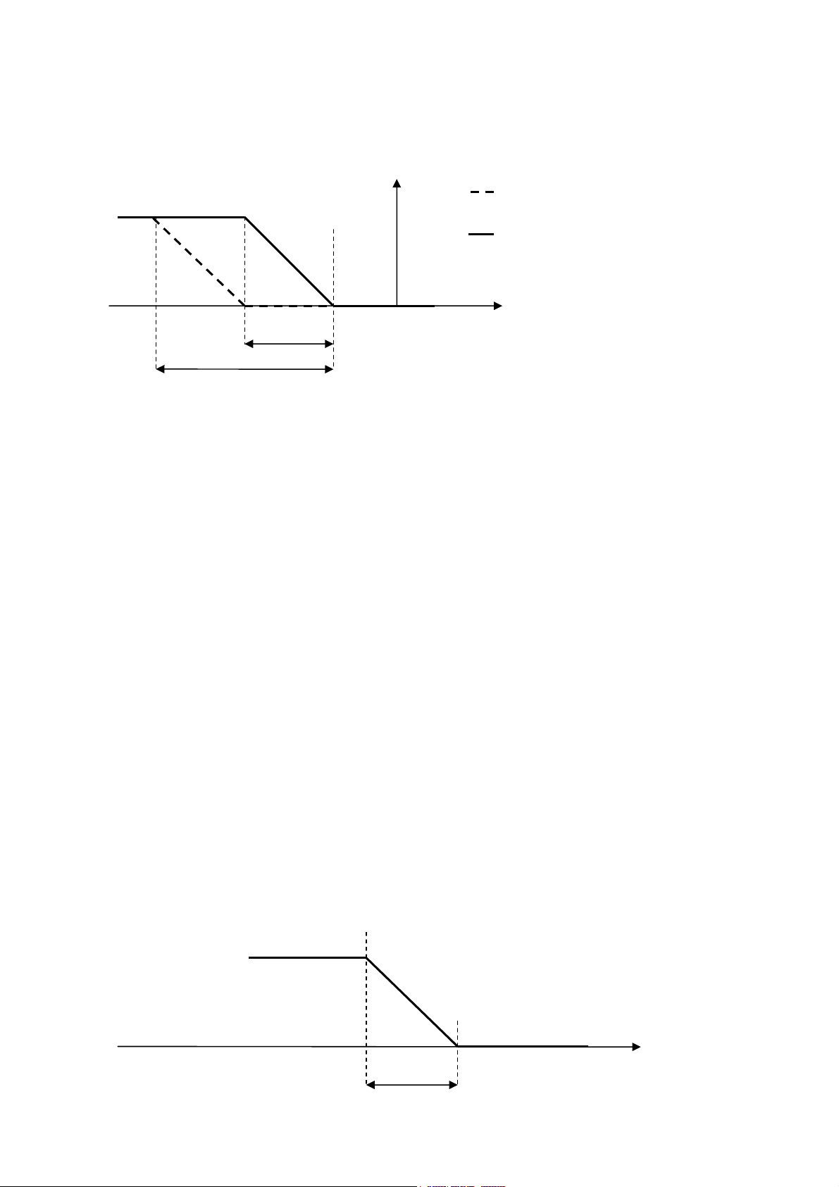
EVCO S.p.A. c-pro 3 micro SAVE/ c-pro 3 kilo SAVE | Application Manual ver. 1.0 | Code 144CP3UKSAE104
Point
Tem
perature
Pb02
Pb02
/ 2
100 %
0 %
0%
Supply
Pb02: Diff
100%
EVCO
Set
Heating
Free-heating
Note: If one of the probes is involved in the regulation error in the adjustment of the free-heating is no longer usable
and the ramp of the heating rule on the total of the control differential.
If the adjustment is used for changing the air at the request of a specific probe of CO2 according to the control probe,
the setpoint (PS20) and to the relative differential (PS21) is actuated damper.
Note: If the air quality sensor is in error adjustment is inhibited.
6.8.5 Heating
The COMPLETE solution offers the possibility to use a hot water coil or a set of three electric heaters for space heating
purpose. By setting the PG02 parameter the desired resource is activated along with the relevant alarms connected.
For using this function it is necessary to enable the supply temperature probe setting PH40=1.
During the anti-freeze protection of the recovery heat exchanger, on units without by-pass, the heating source must
be deactivated for protection. The heating source is disabled with a delay defined at the parameter PF09 after the fan
speed has reduced to V1 during the supply fan speed decrease for antifreeze protection. If the antifreeze condition
remains active for further PF09 the supply fan is stopped.
6.8.5.1 Heating with hot water coil
To use the hot water coil for space heating it is required to set the parameter PG02=1. The control is based on the
supply temperature via a supply Set Point (SPHM parameter) and a relevant differential (Pb02 parameter). The coil is
controlled via a proportional-integral algorithm (PI). The control can be only proportional by setting the integral time
Pb03=0.
page 52 of 68
Page 53

EVCO S.p.A. c-pro 3 micro SAVE/ c-pro 3 kilo SAVE | Application Manual ver. 1.0 | Code 144CP3UKSAE104
0%
supply
T.
Pb02: Diff
100%
1st
heater
Pb02
2nd
heater
3rd
heat
er
SPHM: Outlet
Supply Temperature
EVCO
In case the control probe has an alarm condition it is possible to decide the opening percentage of the coil valve during
alarm setting the Pb04 parameter. If Pb04 = 0.0% in probe error condition the valve remains closed.
Anti-freeze safety on hot water circuit (AL04)
The anti-freeze mechanical thermostat (digital input DI6) is mounted downstream the coil either inside or outside the
pipe. On its intervention (voltage free contact closure on controller digital input), the controller carries out the
following steps:
a) Open the 3-way valve completely (hot water)
b) Close the fresh air damper
c) Stop the fans
This alarm is enabled by setting PA08=1 and is only active if the hot water coil is enabled (PG02=1). The alarm is
signalled after a set delay (parameter PA09) and is reset automatically.
6.8.5.2 Heating with electric heaters analog
To use the electric heaters for space heating purpose it is necessary to set the parameter PG02=3.
The adjustment is the same as the water battery, is controlled by an algorithm proportional-integral (PI), the
adjustment can be only proportional setting the integral time Pb03 = 0.
6.8.5.3 Heating with electric heaters (3 stages)
To use the electric heaters for space heating purpose it is necessary to set the parameter PG02=2. The control is
based on the supply temperature via a supply Set Point (SPHM parameter) and a relevant differential (Pb02
parameter.
Between following activation / de activation of the heaters a delay has been implemented (parameter Pb05) in order to
prevent for simultaneous current peaks.
page 53 of 68
Page 54

EVCO S.p.A. c-pro 3 micro SAVE/ c-pro 3 kilo SAVE | Application Manual ver. 1.0 | Code 144CP3UKSAE104
EVCO
In case the control probe has an alarm condition it is possible to decide the number of heaters to be activated during
the the alarm by setting the Pb06 parameter. If Pb06=0 in probe error condition no heater is active.
Heaters thermal overload alarm
Via the DI6 (Electric heaters thermal overload protection) digital input it is possible to activate the heaters thermal
overload alarm. On occurrence of this alarm the heaters are immediately switched OFF. The alarm is signalled after a
fixed delay of 2 seconds and is reset automatically. The alarm is enabled by setting PA12=1. The alarm can be enabled
only if the heaters are configured (PG02=2, PG02=3).
6.8.5.4 Heaters status
Each of the three heaters can assume one out the following status:
1. Disabled: the heater is not managed by control.
2. Off: the heater is not active.
3. In switch-ON stand-by: the heater is about to switch-ON, it is in stand-by due to protection times.
4. In switch-OFF stand-by: the heater is about to switch-off, it is in stand-by due to protection times.
5. On: the heater is active.
6. Alarm: the heater is blocked due to the relevant thermal overload alarm.
7.
6.8.5.5 Heaters over temperature protection with
automatic reset
By setting the parameter PA16=1(high temperature) it is possible to decide whether to use the supply high
temperature alarms or not. The following parameters must be configured in order to use these alarms:
- PA17 = Automatic reset over temperature protection Set Point
- PA19 = Temperature alarm differential
- PA20 = Temperature alarm activation delay
The alarms are signalled after the PA20 delay time have automatic reset. The alarms are disabled in case of alarm
condition on the supply temperature probe. These alarms can only be activated with the unit running.
6.8.6 Heat exchanger by-pass in summer mode (Free-
Cooling)
During summer cycle, when the outside temperature is low enough it is possible to take advantage of the outside air
for cooling down the internal ambient by means of the by-pass damper. Set PG08=1 to enable this function. This
function uses the outside air temperature probe (TExt) and the return temperature probe (TInt).
When TExt ≥ Tke (default 15 °C, it can be modified by parameter Pr04) and return temperature TInt ≥ Tki (default 22
°C, it can be modified by parameter Pr05) and if TExt ≤ TInt the function is active and opens the heat exchanger by-
pass damper.
Note: To use this function the outside and return temperature probes must be enabled, respectively PH43=1 and
PH41=1. If one of the two probes is in error condition the function is disabled.
page 54 of 68
Page 55

EVCO S.p.A. c-pro 3 micro SAVE/ c-pro 3 kilo SAVE | Application Manual ver. 1.0 | Code 144CP3UKSAE104
0%
CO PF15: Diff
100%
Max Vel.
-
Pb/2
+Pb/2
Fan Speed
Min Vel.
Pressure (Pa)
Setpoint
EVCO
6.8.7 Modulation of the air flow with CO
This function is enabled only at the times COMFORT. It provides for the modulation of fan speed according to the value
read by the probe of CO2 and is activated by setting PF01 = 3. The speed modulation takes place according to a PI
control (if PF17 = 0 only proportional control).
PF16 = 1 with parameter adjustment is a ramp like the following:
probe
2
PF14:Set
In case of parameter PF16 = 0 the adjustment is in steps, the steps are calculated according to the previous ramp broken within the
values indicated by the parameters PF21 (value variable speed corresponding to the speed V1), PF22 (value variable speed
corresponding to the speed V2 ), PF23 (value variable speed corresponding to the speed V3)
Note: To use this feature, you must enable the CO2 probe (parameter PH42 = 1) and the relative values of linearization (parameters
PH03 and PH04).
6.8.8 Adjusting the static pressure
This feature provides for the modulation of the fan speed as a function of the pressure of canale.e is activated by setting PF00 = 1. The
speed modulation takes place according to a PI control (if PF37 = 0 only proportional control).
PF31
PF30
The static pressure setpoint supply air is moved up slowly from 0 to the setpoint target when you start the central
unit. The ramp time is defined by parameter PF32, setpoint adjustment ramp static pressure.
PF30: minimum fan speed
PF31: maximum fan speed
PF32: Adjust the static pressure setpoint ramp
page 55 of 68
Page 56

EVCO S.p.A. c-pro 3 micro SAVE/ c-pro 3 kilo SAVE | Application Manual ver. 1.0 | Code 144CP3UKSAE104
EVCO
PF33: Adjust the static pressure setpoint V1
PF34: V2 static pressure setpoint adjustment
PF35: Adjust the static pressure setpoint V3
PF36: Proportional pressure control static
PF37: Integral time for static pressure
PH44: Enable static pressure probe
PH46: pressure sensor probe
PH07: minimum threshold value for the probe pressure (Pa)
PH08: maximum threshold value for the probe pressure (Pa)
If PH44 = 1 Fan speed is equal to the supply and return fans.
If PH44 = 2 The fan speed is independent for supply and extract (pressure1 for channel flow and pressure for 2
channel recovery.)
6.8.9 Heating control depending on Return Air Temperature
It is possible to decide whether to control the space heating (by means of hot water coil or electric heaters) depending
on the return ait temperature instead of on the supply air temperature (Pb01=0). To use this function set Pb01=1 and
also set the SPHR parameter indicating the value of the regulation set point on the return air temperature. To use of
this the return air temperature probe must be enabled (PH41=1).
6.8.10 Alarm fire/smoke
This function is activated by parameter PA51. This parameter is used to determine the speed of the fans (return and
supply).
Here are the values:
• PA51 = 0: Disabled
• PA51 = 1: Stop (Fire Unit OFF)
• PA51 = 2: Stop V3 + supply fan - Fan recovery V3
• PA51 = 3: Stop + V0 supply fan - Fan recovery V3
The alarm is reset automatically and immediately reported.
7. DIAGNOSTICS
The application can manage a series of alarms relevant to the fans and the devices configured. Depending on the
various types of alarm it is possible to configure a manual or automatic reset, a possible delay and the actions to carry
out in the specific case.
When one or more alarms are active the alarm icon on the main page flashes, if configured (PH20=1) and only
with the machine ON the buzzer is also activated.
To display the alarms, select ALARMS on the general menu or press ESC from the main page and then select “Show
ALARMS >>”.
If the ESC key is pressed on an alarm page or you wait 60 seconds for timeout, go back to the main page of the
application. To scroll through the various active alarms, press ENTER again: the alarms are presented in the order of
priority, as they are listed in the alarms table.
To silence the buzzer, press the
Vgraph
down key for about 2 seconds.
page 56 of 68
Page 57

EVCO S.p.A. c-pro 3 micro SAVE/ c-pro 3 kilo SAVE | Application Manual ver. 1.0 | Code 144CP3UKSAE104
(*1
)
(*1)
(*1)
(*2)
(*2)
EVCO
7.1 Manual and automatic reset alarms
As shown previously there are two types of alarm. Those with manual reset and those with automatic reset. For some
alarms it is possible to set (Alarms Reset) the most suitable type of reset for user needs by means of the relevant
parameters. Other alarms have predetermined reset type.
7.1.1 Manual reset alarms
If a manual rest alarm occurs the alarm icon starts to flash and the buzzer is activated (if configured PH20=1).
Once the conditions for which the alarm has occurred are reset it is possible to manual reset the alarm. To perform
this operation:
⋅ Enter the relevant alarm page
⋅ hold the ENTER key down for about 2 seconds.
At this point, if there are no other active alarms, the page indicating “NO ALARMS” will be displayed, the icon
disappears, the buzzer switches off and the unit starts working normally. If there are other active alarms the page
relevant to the next active alarm will be displayed.
The consequences relevant to an active manual reset alarm remain valid until the user reset the alarm message.
7.1.2 Automatic reset alarms
If an automatic reset alarm occurs the alarm icon starts to flash and the buzzer is activated (if configured PH20=1).
Once the conditions for which the alarm occurred are reset the alarm message and the relevant consequences are
reset automatically without need of user intervention.
7.2 Alarms table
Below is a list of all alarms managed by the application. The order of presentation is the same as the order of active
alarms occurrence. The alarms can be displayed also with the machine in OFF status.
Code Alarm description Reset Consequence Delay
AL01 Supply fan thermal overload
AL02 Return fan thermal overload
AL03 Differential pressure switch
AL04 Hot water coil anti-freeze Automatic
AL05
Electric heaters thermal overload – manual
reset
Outside air damper limit switch “completely
(*1)
AL06
AL07
open”
Outside air damper limit switch “completely
closed”
Electric heaters thermal overload – automatic
reset
(*1)
AL09 Supply fan running hours Manual
AL10 Return fan running hours Manual
Automatic Switches all devices off Fixed 2 s
Automatic Switches all devices off Fixed 2 s
Manual Switches all devices off Selectable
- Open the hot water valve
completely
- Close the fresh air damper
Selectable
- Switches fans OFF
Manual Switches the heaters OFF Fixed 2 s
Manual Switches all devices off Selectable
Automatic Switches the heaters OFF Selectable
Signalling only -
Signalling only -
page 57 of 68
Page 58

EVCO S.p.A. c-pro 3 micro SAVE/ c-pro 3 kilo SAVE | Application Manual ver. 1.0 | Code 144CP3UKSAE104
EVCO
AL11 Anti-freeze temperature probe Automatic Inhibits the relevant control Selectable
AL12 Supply air temperature probe Automatic Inhibits the relevant control Selectable
AL13 Return air temperature probe Automatic Inhibits the relevant control Selectable
AL14 CO2 probe Automatic Inhibits the relevant control Selectable
AL15 Outdoor intake air temperature probe Automatic Inhibits the relevant control Selectable
AL16 Pressure probe1 Automatic Inhibits the relevant control Selectable
AL17 Pressure probe2 Automatic Inhibits the relevant control Selectable
AL18 Alarm fire/smoke Automatic Inhibits the relevant control Selectable
AL19 RTC alarm failure or unloading Manual
Inhibits the management of the
RTC regulation
-
(*1) These alarms cause the unit to switch OFF (OFF due to alarm status)
(*2) To reset the alarms linked to running hours just reset the device hours.
7.3 General alarm relay
The controller manages a configurable alarm relay. For each alarm there is a parameter which selects whether that
alarm must be signalled on the alarm relay. Several alarms can be addressed to the relay.
Via the relevant parameter (PH61) it is possible to establish the polarity (NO, or NC) of the alarm relay.
7.4 Alarms log
The controller record the ALARMS LOG in a non-volatile area of the memory organised as FIFO (First In First Out), that
is a list of the last 100 alarms occurred.
To display the alarms log, select LOG from the General menu or press ESC from the main page to display this page:
Move the cursor on “Show HISTORIAN>>>” and push the Enter key. The alarms log screen will be displayed:
Each element of the log has the following information associated:
- Alarm running number
page 58 of 68
Page 59

EVCO S.p.A. c-pro 3 micro SAVE/ c-pro 3 kilo SAVE | Application Manual ver. 1.0 | Code 144CP3UKSAE104
EVCO
- Alarm mnemonic code (AL01, AL03, …)
- Alarm occurrence date and time
- A possible value associated to the alarm
The alarm mnemonic code is the one shown in the alarms table. The log can hold 100 events.
Via the PH18 (Delete alarms log) parameter it is possible to cancel all the alarms stored in the log. Set the parameter
at SI (1) and wait a few seconds for the NO (0) default value to be read again.
Note 1: The storing in the log of an alarm beyond the maximum number allowed (100) means
the first alarm of the log is overwritten.
page 59 of 68
Page 60

EVCO S.p.A. c-pro 3 micro SAVE/ c-pro 3 kilo SAVE | Application Manual ver. 1.0 | Code 144CP3UKSAE104
EVCO
8. MODBUS VARIABLES
The controller can be managed by a supervisor via Modbus protocol. The communication takes place via optional
TTL/RS485 serial interface outside the controller. The various states/parameters exported from the controller are
shown below.
8.1 ModBus exporting table
Addr
Base 0
Addr
Base
1
REGISTER VARS LIST
Name Value Min Max Description Mode BMS
Bit1=DI1, Bit2=DI2,
0x0100 257 Packed_DI 0 0 65535
Bit3=DI3, ...,
Bit13=DI13,
R/W
Bit14=DI14
Bit1=DO1, Bit2=DO2,
0x0180 385 Packed_DO 0 0 65535
..., Bit13=DO13,
R/W
Bit14=DO14
0x0200 513 AI01_Antireeze_Probe 0.0 -3276.8 3276.7 R/O
0x0201 514 AI02_AirSupply_Probe 0.0 -3276.8 3276.7 R/O
0x0202 515 AI03_AirReturn_Probe 0.0 -3276.8 3276.7 R/O
0x0203 516 AI04_AirExternal_Probe 0.0 -3276.8 3276.7 R/O
0x0204 517 AI07_CO2_Probe 0 -32768 32767 R/O
0x0205 518 AI08_Press1_Probe 0 -32768 32767 R/O
0x0206 519 AI09_Press2_Probe 0 -32768 32767 R/O
0x0281 642 AO01_Heaters 0.00 0.00 100.00 R/O
0x0282 643 AO02_Heating 0.00 0.00 100.00 R/O
0x0283 644 AO03_ByPass 0.00 0.00 100.00 R/O
0x0284 645 AO04_ReturnFan 0.00 0.00 100.00 R/O
0x0285 646 AO05_SupplyFan 0.00 0.00 100.00 R/O
0x0286 647 AO06_Recyclage 0.00 0.00 100.00 R/O
Bit1=AL01,
Bit2=AL02,
Bit3=AL03,
Bit4=AL04,
Bit5=AL05,
Bit6=AL06,
0x0300 769 PackedAlarm_1 0 0 65535
Bit7=AL07, Bit8=free,
Bit9=AL09,
R/W
Bit10=AL10,
Bit11=AL11,
Bit12=AL12,
Bit13=AL13,
Bit14=AL14,
Bit15=AL15,
page 60 of 68
Page 61

EVCO S.p.A. c-pro 3 micro SAVE/ c-pro 3 kilo SAVE | Application Manual ver. 1.0 | Code 144CP3UKSAE104
EVCO
Bit16=AL16
Bit1=AL17,
Bit2=AL18,
Bit3=AL19,
Bit4=AL20,
Bit5=AL21,
0x0301 770 PackedAlarm_2 0 0 65535
Bit6=AL22,
Bit7=AL23, Bit8=Free,
R/W
Bit9=AL25,
Bit10=AL26,
Bit11=AL27,
Bit12=AL28,
Bit13=AL29
0x0400 1025 Status_OnOff_bySUP 0 0 1 R/W
0x0500 1281 CLOCK_RTC ( Low ) - 01/01/2000
19/01/2068
03:14:07
R/W
0x0501 1282 CLOCK_RTC ( High )
0x0502 1283 StatusUnit 0 0 5 R/W
0x0503 1284 UI_MainLabelDown 0 0 8 R/W
0=Disabilitato, 1=OFF,
0x0504 1285 Status_SupplyFan 0 0 9
2=Wait ON, 3=ON,
4=Wait OFF, 5=ALL,
R/W
6=Manual
0=Disabilitato, 1=OFF,
0x0505 1286 Status_ReturnFan 0 0 9
2=Wait ON, 3=ON,
4=Wait OFF, 5=ALL,
R/W
6=Manual
0x0506 1287 UI_byPassAntiFreeze 0 0 1 R/W
0x0507 1288 Status_AirNEUF 0 0 5 R/W
0x0508 1289 byPassRecover_Summer 0 0 1 R/W
0=Disabilitato, 1=OFF,
0x0509 1290 Status_Resistor1 0 0 5
2=Wait ON, 3=ON,
R/W
4=Wait OFF, 5=ALL
0=Disabilitato, 1=OFF,
0x050A 1291 Status_Resistor2 0 0 5
2=Wait ON, 3=ON,
R/W
4=Wait OFF, 5=ALL
0=Disabilitato, 1=OFF,
0x050B 1292 Status_Resistor3 0 0 5
2=Wait ON, 3=ON,
4=Wait OFF, 5=ALL
0x050C 1293 active_ProbeHeating 0.0 -3276.8 3276.7 R/O
0x050D 1294 active_SetPointHeating 0.0 -20.0 230.0 R/W
0x050E 1295 active_HeatingPower 0.00 0.00 100.00 R/W
0x050F 1296 Status_MixAirShutter 0 0 5 R/W
0x0510 1297 Request_AirQuality 0.00 0.00 100.00 R/W
0x0511 1298 Req_FreeCoolingHeating 0.00 0.00 100.00 R/W
0x0606 1543 SPHR_SetPoint_Return 20.0 -20.0 230.0 R/W
0x0607 1544 SPHM_SetPoint_Supply 22.0 -20.0 230.0 R/W
page 61 of 68
R/W
Page 62

EVCO S.p.A. c-pro 3 micro SAVE/ c-pro 3 kilo SAVE | Application Manual ver. 1.0 | Code 144CP3UKSAE104
EVCO
0x0608 1545 PT01_Start_Confort_TB ( Low ) 08:00:00 00:00:00 23:59:59 R/W
0x0609 1546 PT01_Start_Confort_TB ( High )
0x060A 1547 PT02_Start_Economy_TB ( Low ) 20:00:00 00:00:00 23:59:59 R/W
0x060B 1548 PT02_Start_Economy_TB ( High )
0x060C 1549 PT11a17_TypeDay[0] 0 0 1
0x060D 1550 PT11a17_TypeDay[1] 0 0 1
0x060E 1551 PT11a17_TypeDay[2] 0 0 1
0x060F 1552 PT11a17_TypeDay[3] 0 0 1
0x0610 1553 PT11a17_TypeDay[4] 0 0 1
0x0611 1554 PT11a17_TypeDay[5] 0 0 1
0x0612 1555 PT11a17_TypeDay[6] 0 0 1
0=Sunday,..
6=Saturday
0=Sunday,..
6=Saturday
0=Sunday,..
6=Saturday
0=Sunday,..
6=Saturday
0=Sunday,..
6=Saturday
0=Sunday,..
6=Saturday
0=Sunday,..
6=Saturday
R/W
R/W
R/W
R/W
R/W
R/W
R/W
0x0613 1556 PM01_Limit_HourFan ( Low ) 8000 0 100000 R/W
0x0614 1557 PM01_Limit_HourFan ( High )
0x0615 1558 PM11_Calibration_AntiFreezeProbe 0.0 -18.0 18.0 R/W
0x0616 1559 PM12_Calibration_AirSupplyProbe 0.0 -18.0 18.0 R/W
0x0617 1560 PM13_Calibration_AirReturnProbe 0.0 -18.0 18.0 R/W
0x0618 1561 PM14_Calibration_CO2_Probe 0 -200 200 R/W
0x0619 1562 PM15_Calibration_AirExternaltProbe 0.0 -18.0 18.0 R/W
0x061A 1563 PM02_SupplyFan_Hours ( Low ) 0 0 100000 R/W
0x061B 1564 PM02_SupplyFan_Hours ( High )
0x061C 1565 PM03_ReturnFan_Hours ( Low ) 0 0 100000 R/W
0x061D 1566 PM03_ReturnFan_Hours ( High )
0x061E 1567 PM90_LastMaintainDATE ( Low )
01/01/2008
00:00:01
01/07/2009
00:00:01
19/01/2068
03:14:07
R/W
0x061F 1568 PM90_LastMaintainDATE ( High )
0=Continue, 1=Auto,
0x0620 1569 PF01_FanRegulationType 0 0 3
2=Auto with DI,
R/W
3=CO2 Probe
0x0621 1570 PF02_SpeedFan_ManualReg 3 0 3 R/W
0x0622 1571 PF03_SpeedFan_Confort 2 1 3 R/W
0x0623 1572 PF04_SpeedFan_Economy 1 0 2 R/W
0x0624 1573 PF05_SpeedFan_ErrorRTC 0 0 3 R/W
0x0625 1574 PF06_MinTimeOnStepsFan 3 0 999 sec R/W
0x0626 1575 PF07_SetPointAntiFreeze 2.0 -20.0 273.0 R/W
page 62 of 68
Page 63

EVCO S.p.A. c-pro 3 micro SAVE/ c-pro 3 kilo SAVE | Application Manual ver. 1.0 | Code 144CP3UKSAE104
EVCO
0x0627 1576 PF08_DiffAntiFreeze 2.0 0.0 20.0 R/W
0x0628 1577 PF09_DeadZoneOutsideTime 5 1 99 Minute R/W
0x0629 1578 PF10_DiffByPassAntiFreeze 2.0 0.0 20.0 R/W
0x062A 1579 PF11_MinTimePostFan 30 0 999 sec R/W
0x062B 1580 PF12_SpeedFan_Confort_DI 3 1 3 R/W
0x062C 1581 PF13_SpeedFan_WeekEnd 0 0 3 R/W
0x062D 1582 PF14_SetCO2 500 0 10000 R/W
0x062E 1583 PF15_bandCO2 600 0 1000 R/W
0x062F 1584 PF21_AOValue_Speed1 33.50 0.00 100.00 R/W
0x0630 1585 PF22_AOValue_Speed2 66.50 0.00 100.00 R/W
0x0631 1586 PF23_AOValue_Speed3 100.00 0.00 100.00 R/W
0x0632 1587 Pb01_HeatRegulationProbe 0 0 1 R/W
0x0633 1588 Pb02_HeatingDiff 10.0 0.0 36.0 R/W
0x0634 1589 Pb03_HeatingCoil_Ti 0 0 999 R/W
0x0635 1590 Pb04_ForceHeat_OnErrorProbe 0.00 0.00 100.00 R/W
0x0636 1591 Pb05_ResistorOnOffDelayTime 60 0 999 R/W
0x0637 1592 Pb06_ResistorOnErrorProbe 0 0 3 R/W
0x0638 1593 PS01_PreStartTime_NEUF_Fan 45 0 65535 R/W
0x0639 1594 PS02_DelayOFF_NEUF 15 0 65535 R/W
0x063A 1595 PS05_FineCorsa_WaitTime 60 0 999 R/W
0x063B 1596 Pr01_SetPoint_MinTemp_HeatRecover 1.0 -20.0 230.0 R/W
0x063C 1597 Pr02_Diff_MinTemp_HeatRecover 2.0 0.0 36.0 R/W
0x063D 1598 Pr03_TimeByPass_Recover 5 1 99 Minute R/W
0x063E 1599 Pr04_SetPointExt_ByPassSummer 15.0 -20.0 230.0 R/W
0x063F 1600 Pr05_SetPointRet_ByPassSummer 22.0 -20.0 230.0 R/W
0x0640 1601 PA01_En_Alarm_HourFan 1 0 1 R/W
0x0641 1602 PA02_HourFanAlarm_Rele 0 0 1 R/W
0x0642 1603 PA03_EnableThermalFanAlarm 1 0 1 R/W
0x0643 1604 PA04_ThemralFanAlarm_Rele 1 0 1 R/W
0x0644 1605 PA05_En_AirFlowPressSwitch 1 0 1 R/W
0x0645 1606 PA06_AlarmAirFlowSwitchDelay 10 0 999 R/W
0x0646 1607 PA07_AlarmAirFlowSwitchDelay_StartUp 60 0 999 R/W
0x0647 1608 PA08_PressSwitchAlarm_Rele 1 0 1 R/W
0x0648 1609 PA09_EnableAntiFreezeCoil 0 0 1 R/W
0x0649 1610 PA10_DelayAlarm_AntiFreezeCoil 10 0 999 R/W
0x064A 1611 PA11_AntiFreezeCoilAlarm_Rele 1 0 1 R/W
page 63 of 68
Page 64

EVCO S.p.A. c-pro 3 micro SAVE/ c-pro 3 kilo SAVE | Application Manual ver. 1.0 | Code 144CP3UKSAE104
EVCO
0x064B 1612 PA12_EnableThermalResistor 1 0 1 R/W
0x064C 1613 PA13_ThermalResistorAlarm_Rele 1 0 1 R/W
0x064D 1614 PA15_FineCorsaAlarm_Rele 1 0 1 R/W
0x064E 1615 PA16_enHighTempAlarm 1 0 1 R/W
0x064F 1616 PA17_SetPointHT 85.0 -20.0 230.0 R/W
0x0650 1617 PA19_Diff_TempAlarm 3.0 0.0 36.0 R/W
0x0651 1618 PA20_TempAlarmDelay 10 0 999 R/W
0x0652 1619 PA21_LT_HT_Alarm_Rele 1 0 1 R/W
0x0654 1621 PA23_IncendieAlarm_Rele 1 0 1 R/W
0x0655 1622 PA24_EnableAlarmRTC 1 0 1 R/W
0x0656 1623 PA25_RTCAlarm_Rele 1 0 1 R/W
0x0657 1624 PA26_AlarmProbe_Delay 10 0 240 R/W
0x0658 1625 PA27_ProbeAlarm_Rele 1 0 1 R/W
0x0659 1626 PH01_MinTempValue -15.0 -20.0 230.0 R/W
0x065A 1627 PH02_MaxTempValue 95.0 -20.0 230.0 R/W
0x065B 1628 PH03_MinPPM_CO2 0 0 10000 R/W
0x065C 1629 PH04_MaxPPM_CO2 1100 0 10000 R/W
0x065D 1630 PH05_Enable_OnOffByDI 1 0 1 R/W
0x065E 1631 PH06_Enable_OnOffBySuperv 0 0 1 R/W
0x065F 1632 PH11_Modbus_Address 1 1 247 R/W
0x0660 1633 PH12_Modbus_Baud 3 0 4 R/W
0x0661 1634 PH13_Modbus_Parity 2 0 2 R/W
0x0662 1635 PH14_Modbus_StopBit 0 0 1 R/W
0x0663 1636 PH18_HistoryReset 0 0 1 R/W
0x0664 1637 PH20_EnableBuzzer 1 0 1 R/W
0x0665 1638 PH30_TemperatureUM 0 0 1 R/W
0x0666 1639 PH40_EnableAirSupplyProbe 1 0 1 R/W
0x0667 1640 PH41_EnableAirReturnProbe 1 0 1 R/W
0x0668 1641 PH42_EnableCO2Probe 1 0 1 R/W
0x0669 1642 PH43_EnableAirExternalProbe 1 0 1 R/W
0x066A 1643 PH51_Logic_DI1 0 0 1 0=NO, 1=NC R/W
0x066B 1644 PH52_Logic_DI2 0 0 1 0=NO, 1=NC R/W
0x066C 1645 PH53_Logic_DI3 1 0 1 0=NO, 1=NC R/W
0x066D 1646 PH54_Logic_DI4 1 0 1 0=NO, 1=NC R/W
0x066F 1648 PH56_Logic_DI5 1 0 1 0=NO, 1=NC R/W
0x0670 1649 PH57_Logic_DI6 0 0 1 0=NO, 1=NC R/W
page 64 of 68
Page 65

EVCO S.p.A. c-pro 3 micro SAVE/ c-pro 3 kilo SAVE | Application Manual ver. 1.0 | Code 144CP3UKSAE104
EVCO
0x0671 1650 PH58_Logic_DI7 1 0 1 0=NO, 1=NC R/W
0x0672 1651 PH59_Logic_DI8 0 0 1 0=NO, 1=NC R/W
0x0673 1652 PH60_Logic_DI9 0 0 1 0=NO, 1=NC R/W
0x0674 1653 PH61_Logic_DO_Alarm 0 0 1 R/W
0x0675 1654 PH80_CAN_BaudRate 3 1 4
1=20k ,2=50k, 3=125k,
4=500k
R/W
0x0676 1655 PH99_RestoreDefault 0 0 1 R/W
0x0677 1656 PG01_En_ByPass 1 0 1 R/W
0=Disable, 1=Coil,
0x0678 1657 PG02_HeatingType 3 0 3
2=Resistor DO,
R/W
3=Resistor AO
0x0679 1658 PG03_ByPassDamper_Type 0 0 1 0=DO7, 1=AO3 R/W
0x067A 1659 PG04_Enable_AirNEUF_Shutter 1 0 1 R/W
0x067B 1660 PG05_EnablePostFan 1 0 1 R/W
0x067C 1661 PG06_EnableAntiFreezeType 1 0 2 R/W
0x067D 1662 PG08_Enable_ByPassRecover_Summer 1 0 1 R/W
0x067E 1663 PG09_EnableFineCorsa_AirNEUF 1 0 1 R/W
0x067F 1664 PG10_FanType 0 0 1 R/W
0x0680 1665 PSd1_UserPassword 0 -999 9999 R/W
0x0681 1666 PSd2_InstallerPassword 0 -999 9999 R/W
0x0682 1667 PSd3_CostructorPassword 0 -999 9999 R/W
0x0683 1668 PH32_LanguageUI 0 0 2 0=Eng, 1=Ita, 2=Fre R/W
0x0684 1669 PG00_UnitType 2 1 2
1=Compact,
2=Complete
R/W
0=0-20mA, 1=40x0685 1670 PH45_CO2_sensor 3 0 3
20mA,2=0-5V, 3=0-
R/W
10V
0x0686 1671 Pb07_Heaters_PWM_Time 2 0 20 Sec R/W
0=0-20mA, 1=40x0687 1672 PH46_Pressur_sensor 3 0 3
20mA,2=0-5V, 3=0-
R/W
10V
0x0688 1673 PH47_HeatersAOType 0 0 1 0=0-10V, 1=PWM R/W
0x0689 1674 PA51_TypeFireAlarm 1 0 3 R/W
0x068A 1675 PH07_MinValPressure 0 0 32000 R/W
0x068B 1676 PH08_MaxValPressure 3000 0 32000
R/W
0x068C 1677 PH44_EnablePressProbe 0 0 2 R/W
0x068D 1678 PM16_Calibration_Press1_Probe 0 -2000 2000 R/W
0x068E 1679 PM17_Calibration_Press2_Probe 0 -2000 2000 R/W
0x068F 1680 PF00_Speed_Press 0 0 1 0=speed, 1=press R/W
0x0690 1681 PF16_CO2type 0 0 1 0=step, 1=ramp R/W
page 65 of 68
Page 66

EVCO S.p.A. c-pro 3 micro SAVE/ c-pro 3 kilo SAVE | Application Manual ver. 1.0 | Code 144CP3UKSAE104
EVCO
0x0691 1682 PF17_Ti 0 0 300 R/W
0x0692 1683 PF30_MinSpeedFan 0.00 0.00 100.00 PF03 - Min speed fan R/W
0x0693 1684 PF31_MaxSpeedFan 100.00 0.00 100.00 PF04 - Max speed fan R/W
0x0694 1685 PF32_StaticPressSetPointRamp 300 0 30000 R/W
0x0695 1686 PF33_StaticPressSetPoint1 300 0 30000 R/W
0x0696 1687 PF34_StaticPressSetPoint2 400 0 30000 R/W
0x0697 1688 PF35_StaticPressSetPoint3 500 0 30000 R/W
0x0698 1689 PF36_StaticPressPropBand 200 0 10000 R/W
0x0699 1690 PF37_StaticPressIntegralTime 0 0 300 R/W
0x069A 1691 PF38_ForceOnErrorProbe 30.00 0.00 100.00 R/W
0x069B 1692 PG11_Recyclage 0 0 1 0=Disable, 1=Enable R/W
0x069C 1693 PS06_EnableFreeHeating 0 0 1 0=Disable, 1=Enable R/W
0=FreeCooling/Heating,
0x069D 1694 PS07_Type_ControlShutter 0 0 4
1=AirQuality,
2=Greater 3=Avarage
R/W
4=Fixed
0x069E 1695 PS08_MinRegulationValue_AirExternalShutter 20.00 0.00 100.00
0x069F 1696 PS09_MaxRegulationValue_AirExternalShutter 100.00 0.00 100.00
0x06A0 1697 PS10_FixRegulationValue_AirExternalShutter 50.00 0.00 100.00
0x06A1 1698 PS12_FreeCoolingHeatingTemp_enDiff 2.0 0.0 36.0
0x06A2 1699 PS13_FreeCoolingHeatingTemp_enSetPoint 4.0 0.0 68.0
0x06A3 1700 PS15_EnableMinVal_AirExternalShutter 0 0 2
0x06A4 1701 PS20_AirQuality_SetPoint 600 0 10000
0x06A5 1702 PS21_AirQuality_Diff 100 0 2000
page 66 of 68
0=Disable, 1=Only
Band, 2=Always
R/W
R/W
R/W
R/W
R/W
R/W
R/W
R/W
Page 67

EVCO S.p.A. c-pro 3 micro SAVE/ c-pro 3 kilo SAVE | Application Manual ver. 1.0 | Code 144CP3UKSAE104
EVCO
c-pro 3 micro SAVE/ c-pro 3 kilo SAVE
Application manual ver. 1.0
EB - 36/13
Code 144CP3UKSAE104
This document is exclusive property of EVCO. Reproduction and disclosure are prohibited without express authorisation
from EVCO.
EVCO is not liable for any features, technical data and possible errors stated in this document or deriving from use of
the same.
EVCO cannot be considered liable for damage caused by failure to comply with warnings given in this document.
EVCO reserves the right to make any changes without forewarning, without jeopardising the basic safety and
operating features.
page 67 of 68
Page 68

EVCO S.p.A. c-pro 3 hecto SAVE | Application Manual ver. 1.0 | Code 144CP£SAE104
EVCO S.p.A.
Via Feltre 81, 32036 Sedico Belluno ITALIA
Tel. 0437 / 84.22
Fax 0437 / 83.648
info@evco.it
www.evco.it
page68 of 68
 Loading...