

Page 1

ColorSource Console
User Manual
Version 2.6.0
Part Number: 7225M1200-2.6.0 Rev: A
Released: 2019-04
Page 2

To view a list of trademarks and patents, go to etcconnect.com/ip.
All other trademarks, both marked and not marked, are the property of their respective owners.
ETC intends this document, whether printed or electronic, to be provided in its entirety.
Page 3
Table of Contents
Introduction 1
ColorSource 20 1
ColorSource 40 1
Shutdown 1
Using This Manual 1
Help from ETC Technical Services 2
Register Your Device 3
Online User Forums 3
ColorSource Overview 5
Touchscreen Performance 5
Stage Map 5
Layout Mode 6
Fader Mode 7
Bumps 7
Crossfader 7
Master Faders 7
Getting Started With Patching 9
Patch 9
Add Dimmer 10
Duplicate Cell 10
Add Device 11
Loading a Fixture Profile 12
Remove 12
Show Universes / Show Stage Map 12
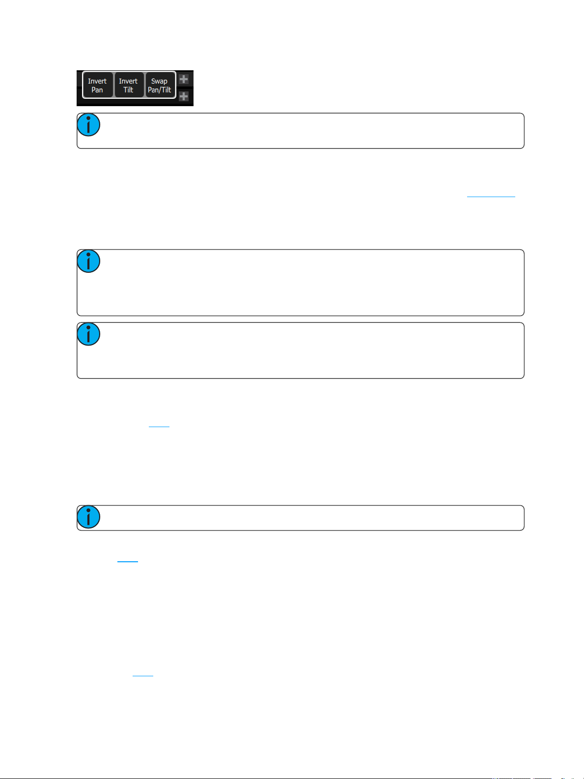
Invert Pan 13
Invert Tilt 13
Swap Pan and Tilt 13
RDM 14
Identify 14
About RDM 14
Controlling Your Lighting System 17
Channels 17
Controls 18
Quick Select 18
Wheel 19
Keypad 19
Controlling Parameters 20
Parameter 20
How to Program a Color Chip. 25
Recording Your Looks For Playback 29
Record / Edit 29
Playbacks 30
Record Cue 32
Record Sequence 37
Operation 39
GO 41
Pause 41
Back 42
Undo 42
Using Effects 43
Effects 43
Page 4
Effect, Color 44
Effect, Shape 44
Effect, Intensity 45
Effect, Parameter 46
Add Effect 47
Remove Effect 48
Turning Lights Off 49
Clear 49
Blackout 50
Special Functions 51
Independent 51
Playback Toy 51
System Settings and Setup 57
Setup 57
Settings 57
Settings: General 57
Settings: Times 58
Settings: Independents 58
Settings: Console 59
Settings: Erase 59
Showfile Management 61
Files 61
Files, Advanced 64
EULA 66
Page 5
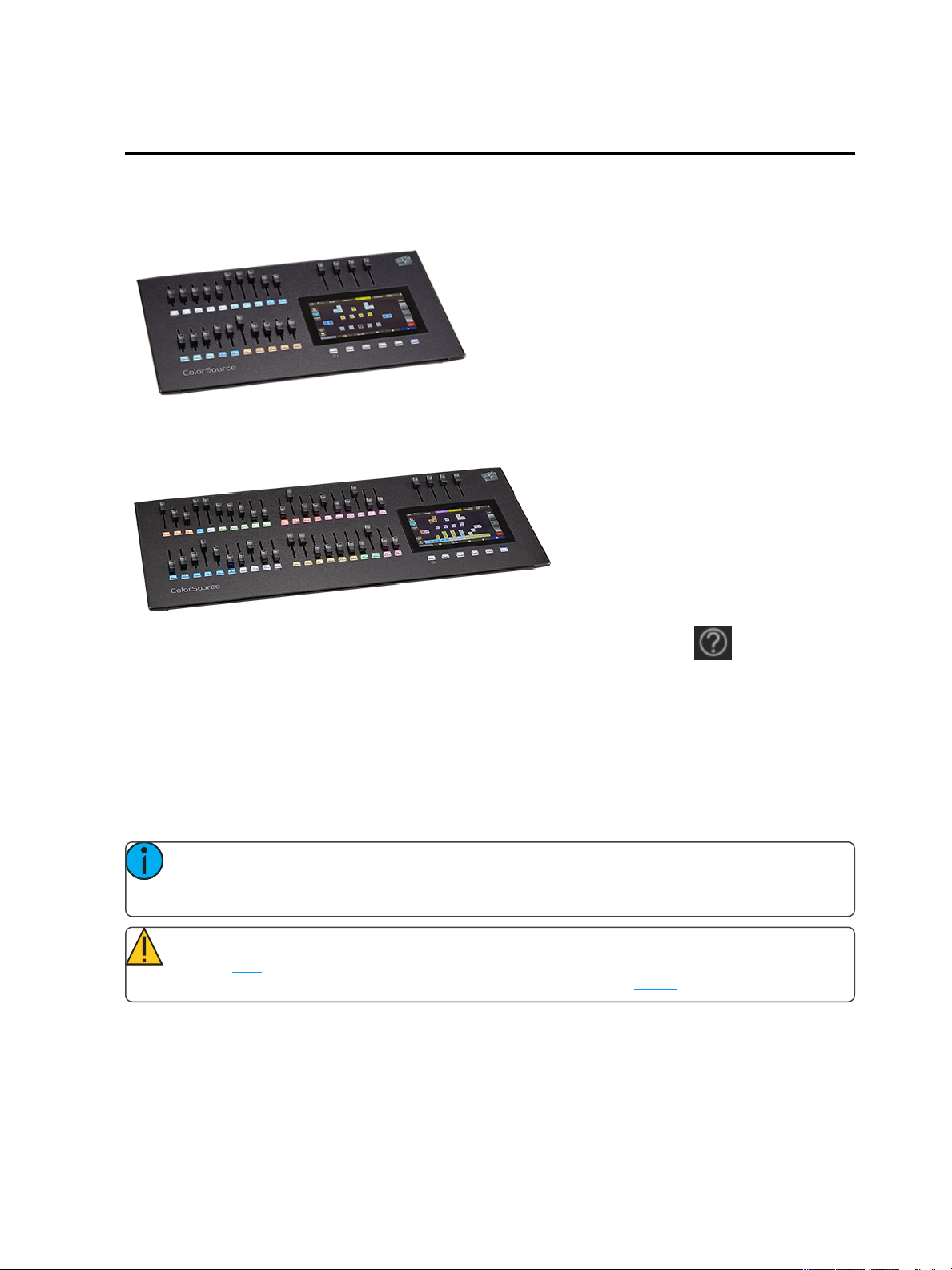
Introduction
Welcome to the ColorSource Console User Manual.
ColorSource 20
ColorSource 40
The topics found in this user manual can also be found on your console by pressing the button.
Tutorial videos are also available on your console.
Shutdown
Hold the Stage Map button (left-most button below the screen) for three seconds to select the Shutdown
screen.
Shutdown sends the console into hibernation mode and turns off the screen and indicators.
To awaken the console, press the now blue Stage Map button again.
Note: When in hibernation mode, the console and its external power supply unit still consume
some power. To ensure zero power consumption, the external power supply should be disconnected
from the AC mains supply.
Caution: All data is stored internally in non-volatile memory. Do not switch off the power until any
pending save operation is completed, or you may lose data. It is strongly advised that you make periodic backups of important data to an external memory stick using the export function.
It is recommended to power the unit on and off on the AC side of the external power supply.
Using This Manual
This manual is for use with ColorSource Console.
Introduction 1
Page 6
In order to be specific about where features and commands are found, the following naming and text conventions will be used:
Buttons, Browser menus, and commands are indicated in bold text. For example: In the File menu,
click Open.
Alphanumeric keyboard buttons are indicated in all CAPS. For example, ALT or CTRL.
References to other parts of the manual are indicated in underlined blue (for example, Patch). When
viewing this manual electronically, click on the reference to jump to that section of the manual.
Note: Notes are helpful hints and information that is supplemental to the main text.
Caution: A Caution statement indicates situations where there may be undefined or unwanted
consequences of an action, potential for data loss or an equipment problem.
Warning: A Warning statement indicates situations where damage may occur, people may be
harmed, or there are serious or dangerous consequences of an action.
Please email comments about this manual to:TechComm@etcconnect.com
Help from ETC Technical Services
If you are having difficulties, your most convenient resources are the references given in this user manual. To
search more widely, try the ETC website at etcconnect.com. If none of these resources is sufficient, contact
ETC Technical Services directly at one of the offices identified below. Emergency service is available from all
ETC offices outside of normal business hours.
When calling for assistance, please have the following information handy:
Model and serial number (located on back panel)
Facility name
Other components in your system ( other control devices, LED fixture types, etc.)
Americas United Kingdom
ETC,Inc. Electronic Theatre Controls Ltd.
TechnicalServices Department TechnicalServices Department
3031 Pleasant View Road 26-28 Victoria IndustrialEstate
Middleton, WI 53562 Victoria Road,
800-775-4382 (USA,toll-free) London W3 6UU England
+1-608 831-4116 +44 (0)20 8896 1000
service@etcconnect.com techservltd@etcconnect.com
Asia Germany
Electronic Theatre Controls Asia, Ltd. Electronic Theatre Controls GmbH
TechnicalServices Department TechnicalServices Department
Room 1801, 18/F Ohmstrasse 3
Tower 1, Phase 1 Enterprise Square 83607 Holzkirchen, Germany
9 Sheung Yuet Road +49 (80 24) 47 00-0
Kowloon Bay, Kowloon, Hong Kong techserv-hoki@etcconnect.com
+852 2799 1220
service@etcasia.com
2 Introduction
Page 7

Register Your Device
Registering your device with ETC ensures that you will be notified of software and library updates, as well as
any product advisories.
To register your device, you will need to enroll in “My ETC,” a personalized ETC website that provides a more
direct path of communication between you and ETC.
Register now at http://www.etcconnect.com/product.registration.aspx.
Online User Forums
You are encouraged to visit and participate in the ETC User Forum, accessible from the ETC web site (etcconnect.com). This gives you access to an online community of users where you can read about other users’ experiences, suggestions, and questions regarding the product as well as submit your own.
To register for the ETC User Forum:
1. Go to ETC’s community web site (community.etcconnect.com).
2. You may register for the forum by clicking the “join” link in the upper right corner of the page.
3. Follow the registration instructions provided by the community page.
Introduction 3
Page 8

4 Introduction
Page 9
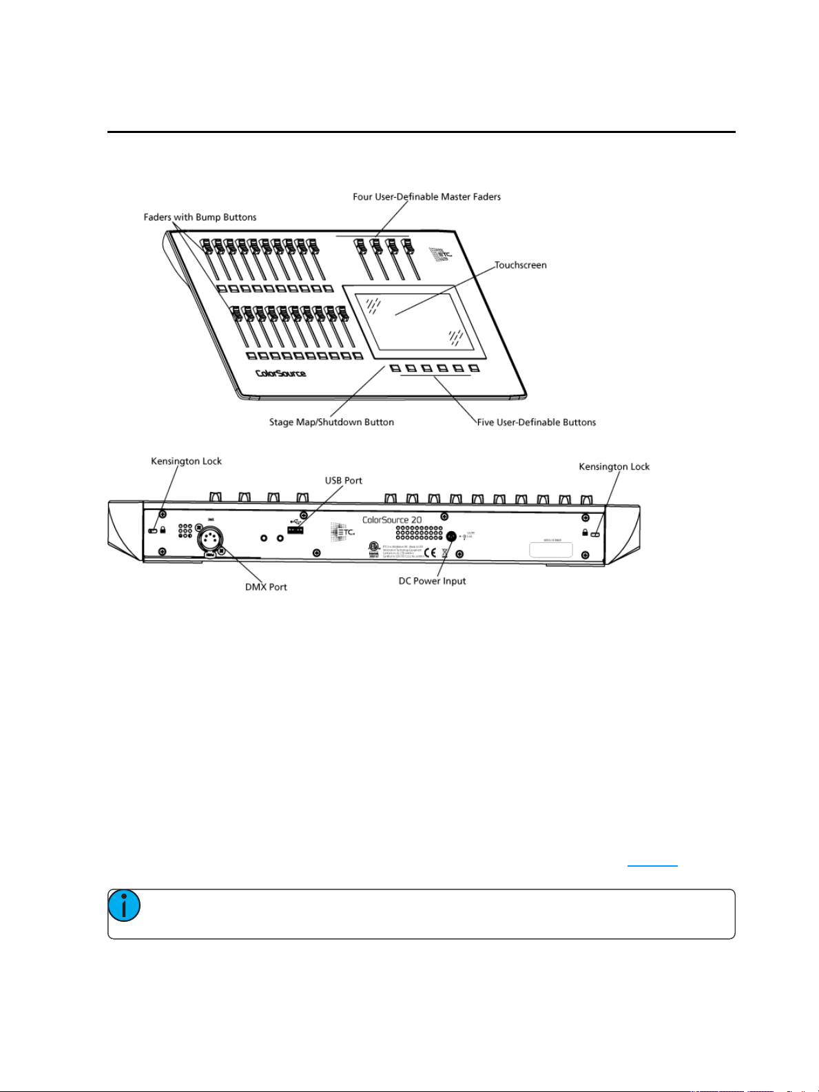
ColorSource Overview
The ColorSource console is made up of four different physical areas; the touchscreen (stage map), the faders
and bumps, the crossfader, and the master faders. It is important to familiarize yourself with these different
areas as you learn to use your console.
Touchscreen Performance
The ColorSource console touchscreen requires that the power supply is grounded (with a three-pin connector)
for optimal performance. Lack of a grounded connection can cause the touchscreen to operate erratically or
not at all. This might be seen as unwanted operations or inability to precisely select an item.
If no earthed / grounded outlet is available, or if the console is being run from an independent power source,
including from a vehicle or battery, it is possible that the touchscreen will not operate correctly. In these situations it is advised to directly connect your body to the console chassis. This may be achieved with a conductive
wrist strap, of the kind used in electronics manufacturing or hospitals to eliminate static charge build-up. The
cable of the strap should be attached to a metallic part of the console, for example a screw or connector on the
rear panel. If this is not practical, then you should at least ensure that you touch the console enclosure, the
metallic part of it, with your wrist or your other hand.
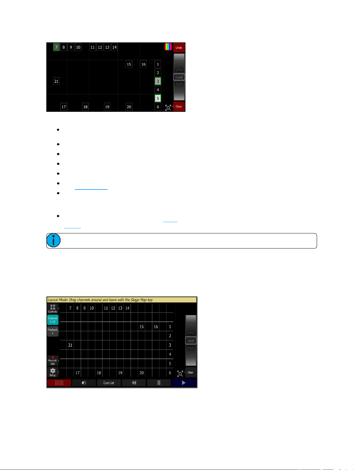
Stage Map
The Stage Map button (left-most button below the screen) displays a topographical map of channels fullscreen
at maximum size. You may select channels on the topographical stage map for control.
Note: The Stage Map button will toggle between displaying the Stage Map or the previously selec-
ted display.
ColorSource Overview 5
Page 10
Available Controls
Pinch two fingers to zoom the display in or out, or use the Zoom button located by Clear. Zoom in to
see intensity levels within the channel cells.
Drag with two fingers to pan the display.
Single click on a deselected light to select it.
Single click on a selected light to deselect it.
Double click on a light to select that light alone and de-select all others.
Use Layout Mode for stage map customization.
Selected lights are indicated surrounded by a green box.
The vertical strip to the right of the main area displays special content that is playing:
Effects: press an icon to Stop or Edit the effect from playback. Press the icon to place the effect on the
wheel controller to increase or reduce the effect.
Note: The Effects icon will only display if that type of content is playing.
Layout Mode
Press and hold a cell on the stage map, or go to Setup >Layout Mode to open the layout screen.
When in layout mode, the screen displays as a grid. Press and drag lights to move them to another position on
the grid.
Press the Stage Map button (left-most button below the screen) to exit the layout mode.
6 ColorSource Overview
Page 11
Fader Mode
The faders to the left of the display may be set to operate individual channels or playbacks.
Two pages of channels are provided and ten pages of playbacks.
Note: See channels for information on faders and captured channels.
Bumps
The buttons below the faders are bump buttons.
Their operation changes based on the fader mode.
When the faders are in channel mode, the bumps can be used to select or deselect channels.
When the faders are in playback mode, their behavior is set based on the selected button mode.
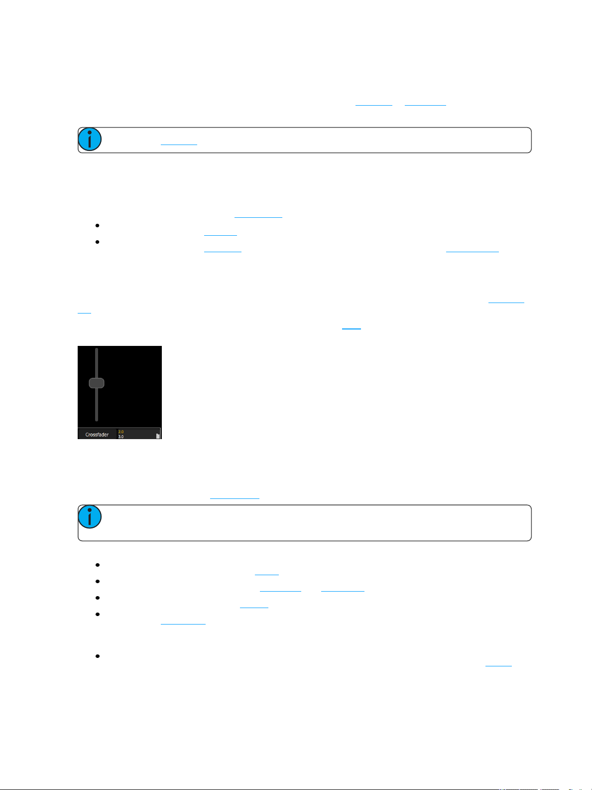
Crossfader
The Crossfader can be assigned to one of the four faders above the touchscreen. It is assigned in the Console
tab in Settings.
The Crossfader provides manual control over the fades between cues. You can see the progress of the crossfade and which cues are affected in the cue viewer.
Master Faders
Master faders can be used to control the output of certain functions. Master faders are assigned to the top four
faders. They are assigned in the Console tab in Settings.
Note: When the Playbacks or Cues faders are fully down no output will be produced by those sec-
tions.
Master faders default to these functions:
Bumps: controls the output when a bump button is pressed.
Playbacks: controls the output of the playbacks and sequences.
Cues: controls the output of the cue list.
Crossfader: Crossfades the cue list from the Live to the Next step.
In Simple Mode
Memory1- 4: The playback memories are the four faders above the touchscreen. You may record the
output and store it on one of the four masters to be re-used later.
ColorSource Overview 7
Page 12

8 ColorSource Overview
Page 13
Getting Started With Patching
To be able to control the lighting fixtures in your system you need to assign each fixture (or a group of dimmers)
to a channel fader. The channel fader can then be used to set intensity of a fixture. The channel also becomes
a way to select that fixture for other types of control like color changes, or adjustment of other parameters (in
the case of a moving light, for example). The fixtures in your lighting system are controlled using the DMX,
streaming ACN, or ArtNet protocols, and each dimmer or fixture uses a DMX address (or set of addresses) to
communicate with the console.
The Patch is used to associate a channel with DMX addresses and device types. Once a channel is patched to
an address or addresses, and the output is connected to a device (for example a dimmer, moving light, or
accessory), the channel will then control that device.
To access the Patch functions, press Setup >Patch.
Note: If your patch stays the same between shows, you can save time by saving a default show,
which will load your patch automatically for you.
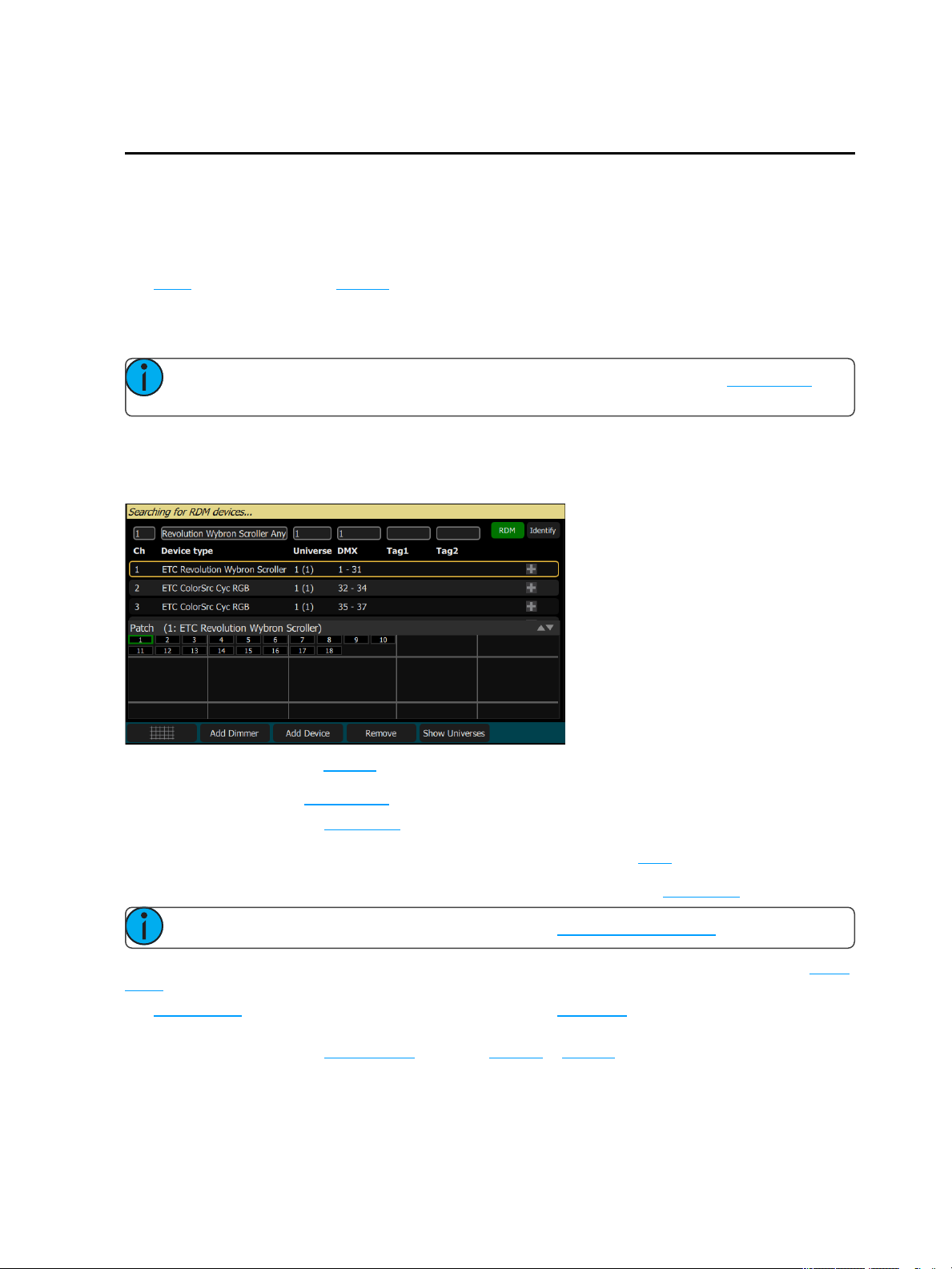
Patch
Displays the patching screen and controls.
Patching associates a console channel number with an address or block of addresses on the DMX output. You
must ensure that the address on the light, dimmer, or device matches the address that you setup in Patch. To
patch a basic device, press Add Dimmer.
Complex devices with several parameters, such as motion, color, or beam controls, are described by a per-
sonality. Select the make and type of device to match the actual connected device. Some devices have modes
that must also match on the device and in the patch list. Lighting devices with RDM available and enabled are
found automatically and added to the list of devices. You must still assign them to console channel numbers
though. To patch a complex device that is not automatically found by RDM, press Add Device.
Note: Custom fixture profiles can be loaded. Please see Loading a Fixture Profile for instructions.
During patching you may add tags to each light, dimmer, or device to aid in convenient grouping on the quick
select screen.
The lower section of the screen may be set to display the channel stage map or a view of the DMX universes
output.
The settings and patch for the independents are on the Ind. Tab in Settings.
Getting Started With Patching 9
Page 14
Add Dimmer
Dimmers are single-address devices that control intensity only. For patching multiple-address devices, see Add
Device.
Note: Dimmer patching can also be used to connect other simple devices that only require one
DMX address.
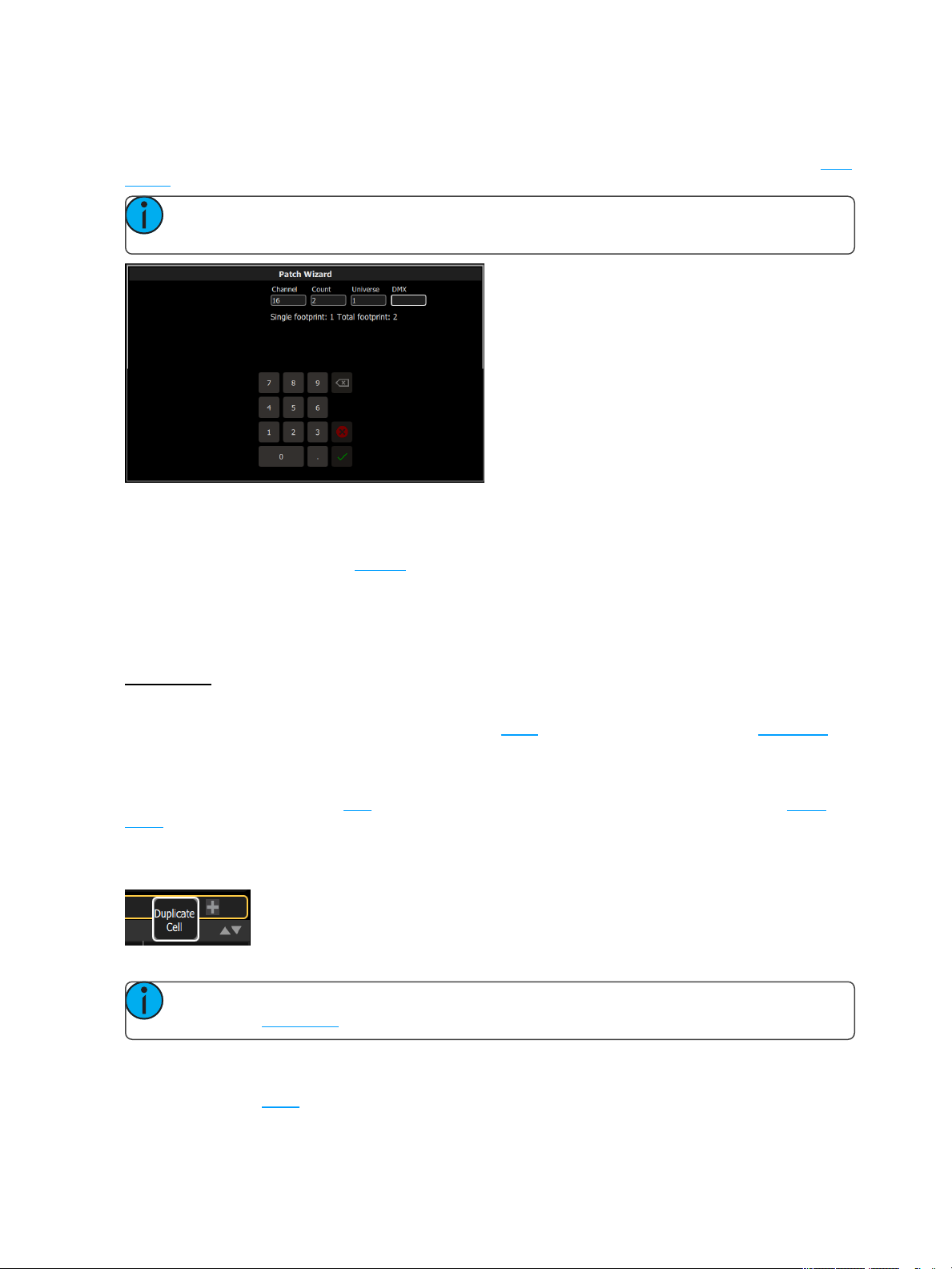
Patching a Dimmer or Single-address Device
1. Press Add dimmer.This will open the Patch Wizard display.
2. Select channel to enter the number.
3. Select Count to enter in the number of similar devices you are patching. If the quantity is more than
one, each dimmer will occupy one DMX address, starting from the address you specify.
4. Select DMX to enter the DMX address (1 through 512).
5. Select Accept to patch, or Cancel to exit.
For Example:
If you set the count to 12 and the DMX address to 20, the devices will occupy DMX addresses 20 through 31.
Patching places the items in a list in the upper part of the patch screen and on the topographical stage map in
the lower part of the screen in rising order starting in the top left corner. You may select one channel at a time
in the list or on the stage map.
Each channel may be edited in the boxes at the top of the screen for channel number, DMX Universe and
DMX address. You may also add tags to each item so that they may be conveniently grouped on the quick
select screen.
Duplicate Cell
Duplicate cell lets you place two dimmers on the Stage Map in different places patched to the same channel.
Note: Duplicate cell adds dimmers only and not devices. Devices must be patched and placed indi-
vidually. See Add Device.
Pick a channel in the patch list and select the + button and then the Duplicate cell button to make a copy.
A new cell is added and is patched to the next-highest free DMX address. You may change the address and universe and set tags in Patch.
10 Getting Started With Patching
Page 15
When a duplicate cell is selected or operated, each of the duplicate cells on the Stage Map will respond
together. Each cell of a duplicate channel may be moved separately on the Stage Map.
Note: You can also add dimmers to a channel without showing them as separate cells on the Stage
Map. Use Add Dimmer and then set the channel number to be the same as the channel you want to
add the dimmer to. Dimmers added in this way do not consume space on the Stage Map, for
instance you may need one channel to control a range of dimmers for house lights without wishing
them to be each placed and indicated separately.
Add Device
Devices are multiple-address lights with a number of controllable parameters, such as position, color, beam,
and intensity. Devices have their own personality, which defines what each parameter does and which controls
are needed.
Note: Lighting devices with RDM available and enabled will be found automatically and added to
the list of devices in the patch. However, you must assign them to console channel numbers.
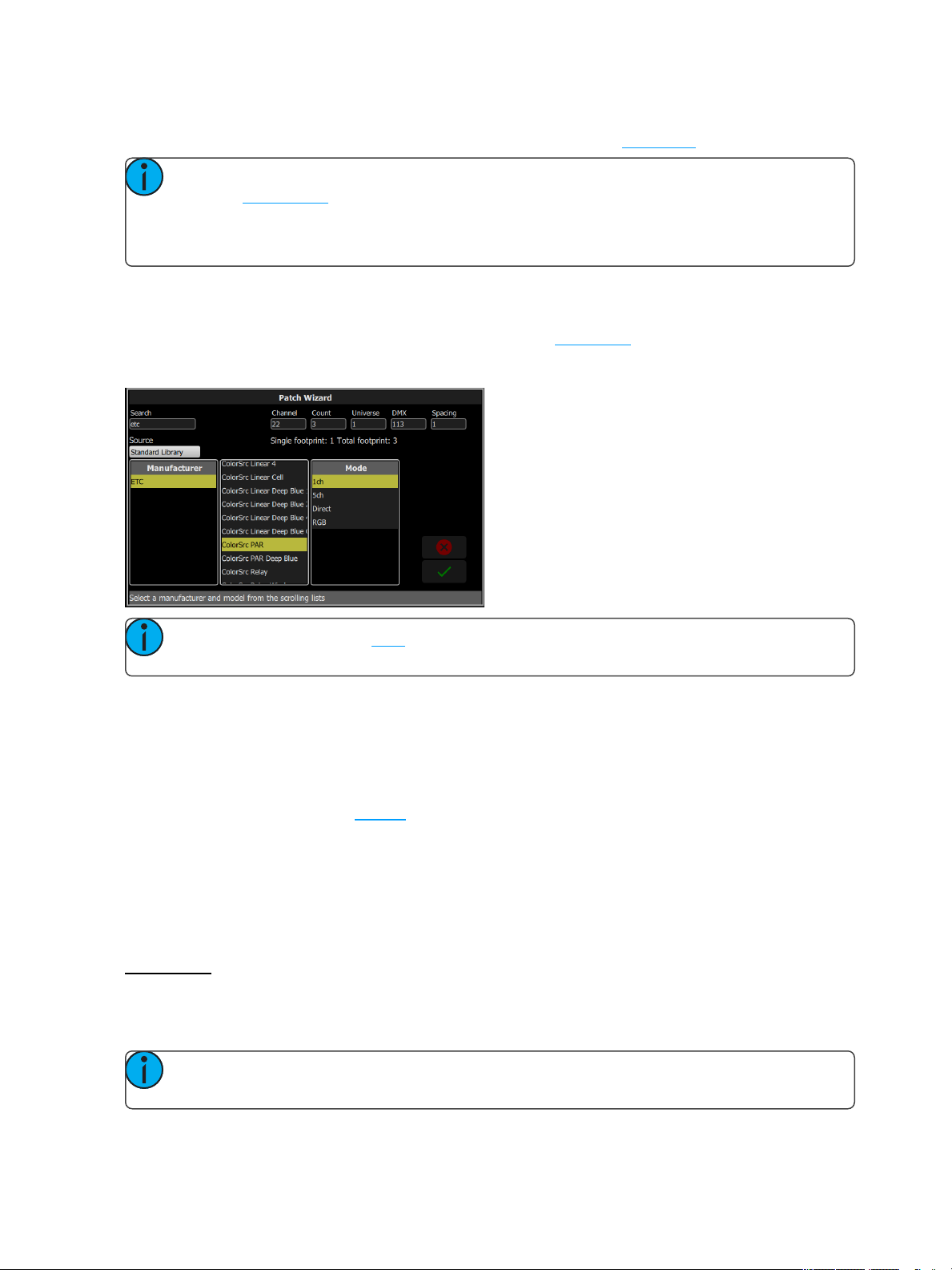
Patching a Device
1. Press Add Device. This will open the Patch Wizard display.
2. Select the correct personality from the list provided. Select the make and type of device to match the
actual connected device. Some devices have modes that must also match on the device and in the
patch list.
3. Select channel to enter the number.
4. Select Count to enter in the number of similar devices you are patching. If the quantity is more than
one, each device will occupy the number of DMX addresses used by its footprint, starting from the
address you specify.
5. Select DMX to enter the starting DMX address.
6. Enter the desired Spacing.
7. Select Accept to patch, or Cancel to exit.
For Example:
If you patch 12 devices with a footprint of 6 DMX addresses each to address 20, they will occupy DMX
addresses 20 through 91.
To patch devices with a gap between them, adjust the Spacing value to a larger number.
Note: Do not adjust this to a smaller number as that will cause overlaps and unexpected behavior
from your devices.
Getting Started With Patching 11
Page 16
For Example:
Your devices use 17 channels, but you would prefer to manually address them at logical starting numbers like
1, 21, 41 and so on. Use the Spacing cell to change the footprint to 20 so that those devices will automatically
patch at 1, 21, 41...
Patching places the items in a list in the upper part of the patch screen and on the topographical stage map in
the lower part of the screen in rising order starting in the top left corner. You may select one channel at a time
in the list or on the stage map.
Each channel may be edited in the boxes at the top of the screen for channel number, DMX Universe and
DMX address. You may also add tags to each item so that they may be conveniently grouped on the quick
select screen.
Note: Custom fixture profiles can be loaded. Please see Loading a Fixture Profile for instructions.
Loading a Fixture Profile
If you have devices in your lighting system that cannot be discovered by RDM and are not included in the
onboard device library, you can create your own personality for that device and import it into your show file.
There is a device editor application for Windows PCs called ColorSource Personality Edit, which is available for
download at www.etcconnect.com.
To request a fixture personality from ETC, please send your request along with the user manual, the required
mode(s) and your need by date to ColorSourceConsole@etcconnect.com.
Note: For the device to recognize the profile, the file name has to be userlib.jlib.
1. You will need to save the file onto the root directory of a USB drive to be able to read it from the device.
2. With the USB drive plugged into the device, go to Setup>Patch>Add Device.
3. From the Source dropdown, select User Library. A new library will display with your fixture listed by its
manufacturer’s name.
Note: Custom device libraries are not stored on the device itself. Please store these custom files on
your USB drive or on another computer for safe keeping.
Remove
Select a device or dimmer, and press Remove to remove from the patch. If you accidentally remove a device
or dimmer, you can use the Undo function to restore it.
The removed item will no longer display on the stage map.
Note: If you have recorded a device into playbacks or cues, and then remove it from the patch, all
the recorded values will remain in the playback or cue, but they will no longer be connected to a
device.
Show Universes / Show Stage Map
The lower section of the Patch screen may be set to display the topographical Stage Map or a chart of the
DMX addresses.
The DMX address chart is view-only and may not be edited. Scroll up and down to view all the addresses in the
selected Universe.
12 Getting Started With Patching
Page 17
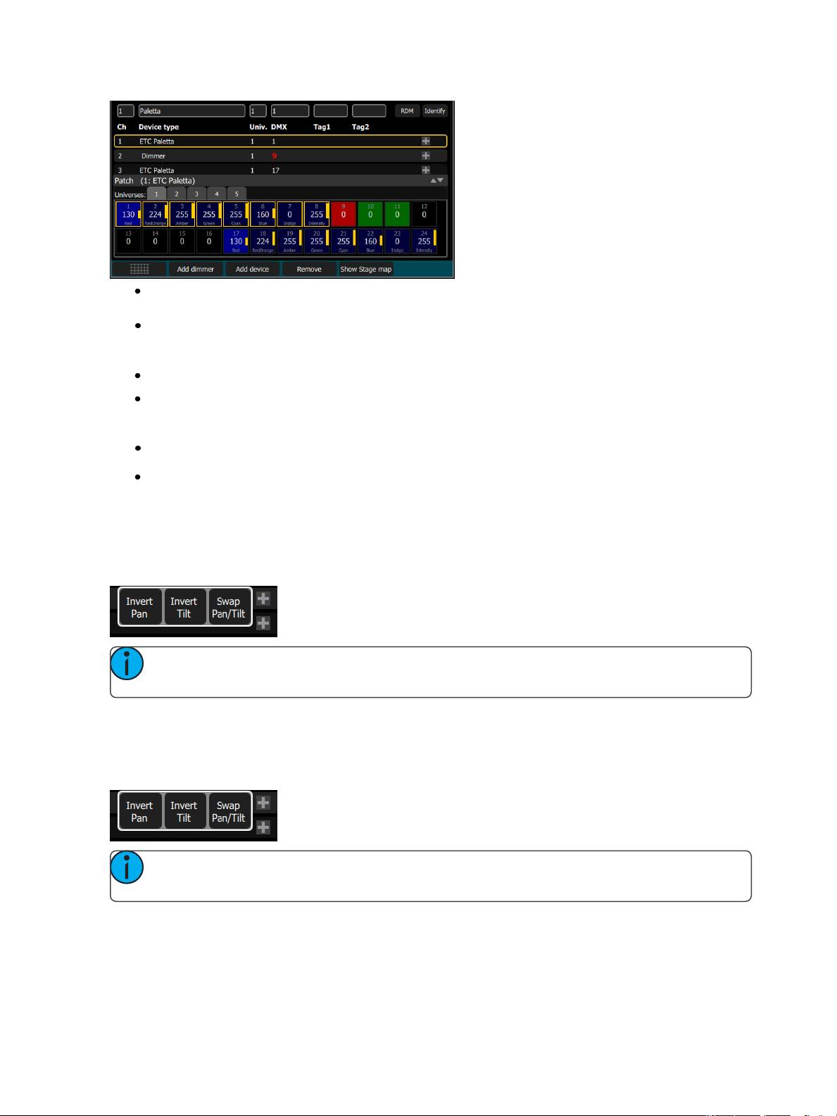
Each cell shows the DMX address, the value in the range 0-255 and the name of the parameter for a
device patched with a personality.
Cells colored in light blue indicate the base address of the item, which is the address entered in the
Patch screen DMX box. The following cells in dark blue show the following DMX addresses used by the
device according to the size of its footprint.
Cells colored in green indicate single dimmers.
Cells colored in red indicate patching overlap, where more than one dimmer or device is patched to the
same DMX address. In some cases it may be desirable to patch with overlaps but usually it is a bad idea
to be avoided if possible.
A yellow bar graph indicates the approximate value being output.
Cells in black are unoccupied and not patched.
Invert Pan
Switches the pan control to run in the opposite direction. Click on the + button in patch for the device you want
to invert pan.
Note: Use this if you have rigged a light upside-down or back-to-front compared to other similar
lights so that if they are all selected together their movements will be in similar directions.
Invert Tilt
Switches the tilt control to run in the opposite direction. Click on the + button in patch for the device you want
to invert tilt.
Note: Use this if you have rigged a light upside-down or back-to-front compared to other similar
lights so that if they are all selected together their movements will be in similar directions.
Swap Pan and Tilt
Exchanges pan and tilt so that pan on the controls tilt on the device and vice-versa. Click on the + button in
patch for the device you want to swap pan and tilt.
Getting Started With Patching 13
Page 18
Note: An example of when to use this function would be if a fixture is hung sideways or a moving
mirror fixture is rotated 90 or 270 degrees from other fixtures.
RDM
RDM is a two-way communications method built-in to ordinary DMX512 for lighting control. See About RDM
for more information.
The RDM button enables or disables RDM on the local DMX port. When enabled, the RDM button will be
green. If you have problems with lights or dimmers connected to the local port on the console that flicker or suffer interference when you open the patch screen try turning off the RDM button.
Note: When you exit the patch screen, all RDM messages are suppressed and only ordinary
DMX512 is sent to your lighting rig on the local ports. The RDM button allows you to turn off RDM
when on the patch screen. Doing so will prevent the patch screen from finding and patching RDM
lights. You should only suppress if necessary to prevent flicker or errors on the local port(s) while you
are in the patch screen.
Note: You may also choose to turn off RDM when you have patched all the lights in a rig that you
wish to use. If the rig contains lights that you do not wish to patch, they will keep appearing in the
patch list, awaiting a number, and you can prevent this from being an annoyance by turning off the
RDM button.
Identify
Identifyfinds the RDM-capable lights during patching so it is easy to know which device is which when assign-
ing them to channels.
When RDM discovers a light, the light is placed at the top of the patch list with the channel shown as zero.
When Identifyis set to On, each light selected in the patch list will identify itself exclusively, usually a light will
blink on and off. Devices that do not produce light, for example a scroller or pan/tilt yoke, may shuffle or move.
The action that a device does when told to Identify is determined by its manufacturer.
You will need to choose a channel to patch the device.
Note: Identify does not work with non-RDM devices or dimmers.
Turn off Identify to stop all RDM Identification. Turn on Identifyto see the currently selected RDM device.
See Also: RDM
About RDM
RDM is a two-way communications method built-in to ordinary DMX512 for lighting control. By using RDM,
you can find lights, find out about them and their status, patch them, and set their operating mode without
needing to go to the light itself. For lights rigged in difficult locations, RDM is very useful for remote setup.
Discovery
RDM automatically discovers RDM-capable lights. Discovery runs continuously any time the Patch screen is
open and the RDM buttonis enabled, and will repeatedly search for devices. As devices are added or removed
from a system, they will be updated in the patch list.
14 Getting Started With Patching
Page 19

Note: Discovery takes place during short periods of rest of normal DMX transmission and is a
lengthy process to complete. You should expect at least several seconds of delay to discover a light
on a small system and much longer delays on a very large system.
Addressing and Mode
RDM allows you to set the DMX address and the operating mode of a light remotely.
Setting the operating mode may change the footprint, which is the number of DMX addresses occupied by the
device. If you change the mode of a device adjacent to some other device or dimmers in patch, the new mode
could be larger than the available space and overlap already used DMX addresses. When this happens, the
affected ones are indicated in the patch list in red, and you will need to take corrective action and re-patch.
The Patch system knows how to match the chosen mode with the correct personality.
Universe
You cannot change the Universe part of the DMX patch for a Device found by RDM. RDM can only operate on
the one universe it is connected to. To change the universe a light is patched to, you must physically re-plug the
light to another DMX cable.
Getting Started With Patching 15
Page 20

16 Getting Started With Patching
Page 21
Controlling Your Lighting System
After you have completed your patch, you are now ready to start controlling your lighting system. Your
ColorSource console gives you many options for control of your lights.
This section discusses how to control your channels, and how to set the parameters.
Note: Depending on the types of lights you have patched, you may have additional parameters
that you can control. Those parameters may include color, position (focus), beam, and lamp com-
mands.
Channels
A channel is the control used by the console to operate a dimmer, a group of dimmers, a dimmer and a device,
or a complete moving light fixture.
Channels need to be associated with an address in patch for there to be output.
Channel Counts
The ColorSource 20 can control up to 20 channels in simple mode, and 40 in complete.
The ColorSource 40 can control up to 40 channels in simple mode, and 80 in complete.
Setting the Operating Mode
Choose Simple or Complete mode on the Setup>Settings>General screen.
Fader Pages
Simple Mode offers one page of faders to control the first 20 or 40 channels, depending on the model.
Complete Mode offers two pages of faders to control all the available channels, 40 or 80 depending on
the model.
Working with Dimmers / Intensity
Channels can be controlled in several different ways:
The faders, when in channel mode, can be used to control a channel's intensity. Depending on the
chosen operating mode: Complete or Simple, there are one or two pages of channels that the faders
can control. In Complete Mode toggle the Channel button to access each of the pages.
Note: The second page of channels is only available when channels have been patched on
that page (above 21 or 41, depending on the console model).
You can use the touchscreen and select channels directly on the stage map. The wheel can then be
used to assign an intensity level.
In complete mode, you can use the keypad to select a channel and assign an intensity level.
In complete mode, channels can also be controlled by the playbacks, sequences, and cues. In simple
mode, channels can be controlled by four playbacks.
Selected Channels
To make changes to channel values, a channel must be selected. Selection is indicated by a thick green border
around the channel cell on the Stage Map and a lit LED beneath the channel fader. Selection can happen in a
number of ways:
Controlling Your Lighting System 17
Page 22
Move a fader to select a channel. If the channel is already on due to playback, move the fader until it
matches the channel's current output. Move the fader back to the bottom "zero" position to deselect it
(and take its intensity to zero.)
Touch the channel cell on the Stage Map. Touch the cell again to deselect it.
Use the Keypad to type in the channel numbers and set levels.
To deselect all selected channels, use Clear>Selection.
Captured Channels
Selected channels that have a manually set intensity level are considered "captured." This means that the
selected channels' levels will be held until the channels are deselected or the manual intensity values are
cleared.
If C lear>Channels is used, cleared manual intensity values will return to the levels coming from active play-
back sources immediately.
If manually set channels are simply deselected, manually set levels will remain on stage until those channels
get a new move instruction from a playback source.
Note: A channel fader moved back to the bottom (or "zero") position will deselect that channel.
You cannot hold a channel at zero intensity using a channel fader. Another selection method must be
used.
Controls
Controls contain all the functions for controlling lights and cues, and setting color and other parameters:
Stage Map: The 'home' view of the full topographical stage map.
Param: Parameter control for moving or automated lights.
Cue List: The cue display.
Playback Toy: A screen to launch lighting looks and play, or busk, live.
Keypad: Classic level control by typing numbers.
Quick Select: Selection of channels in useful blocks or sets.
Effects: Lighting effects for color, intensity, and movement.
Note: Paramis only available if you have patched lights with those capabilities.
Quick Select
In the quick select display, you can pick groups of channels according to their position on the topographical
stage map or by choosing the tags setup during patching.
18 Controlling Your Lighting System
Page 23
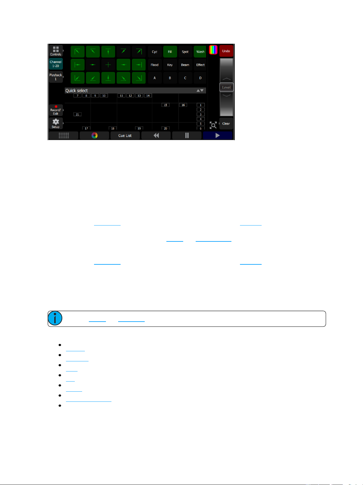
Groups display in the upper section, and the lower section of the screen displays the channel stage map. Available groups are displayed in green boxes. Double click on a group to select only the lights in that group, click
on other groups to add or subtract channels from the selection.
While in the quick select display, the wheel operates the level of the selected channels proportionally. The
group buttons are also variable cells that may be wiped up and down to alter the value.
When you exit the quick select display, the channels will remain selected and colors or other parameters may
be applied to them.
Wheel
To the right of the stage map is the wheel. The wheel can be used to control channel levels by moving the
wheel up to increase the level or down to decrease.
The wheel can also be used to control depth of effects and sequence rate.
In Simple mode
To the right of the stage map is the wheel. The wheel can be used to control channel levels by moving the
wheel up to increase the level or down to decrease.
Keypad
The keypad is opened by going to Controls>Keypad. This provides classic lighting control of channels and
levels via a numeric keypad entry.
Note: Effects and Parameter settings must be controlled on their respective screens.
Available Buttons
+ (Plus)
- (Minus)
Thru
Full
@ (At)
..<<..(Backspace)
Enter
Controlling Your Lighting System 19
Page 24

Keypad, Plus
Adds a channel to the selection set.
For Example:
1 Thru 10 + 20 Enter - creates a set of eleven channels: 1-10 plus 20.
Keypad, Minus
Removes a channel from the selection set.
For Example:
1 Thru 10 - 7 Enter - creates a set of nine channels: 1 through 6 plus 8 through 10.
Keypad, Thru
Selects a range of channels.
For Example:
1 Thru 10 Enter - creates a set of ten channels: 1 through 10.
Keypad, Full
Sets the selected channels to full intensity.
To apply the chosen intensity, you must complete the command with the Enter key.
For Example:
1 @ Full Enter - sets channel one to full intensity.
Keypad, @ (at level)
Sets the selected channels to a level specified in percent % from 0 to 100.
To apply the chosen intensity, you must complete the command with the Enter key.
For Example:
1 + 5 @ 70 Enter - sets channels one and five to 70% intensity.
Keypad, <-- (Backspace)
The <-- key behaves as a backspace button for the command line.
Controlling Parameters
Depending on the types of lights you have patched, you may have additional parameters that you can control.
Those parameters may include color, position (focus), beam, and lamp commands.
Parameter
All the controllable features of an automated light, with the exception of the intensity, are known as the parameters of the light.
Parameters may include position (pan/tilt), color mix, beam control (iris, focus, et cetera), or lamp controls. The
tabs along the top allows viewing of all parameters or only a selected type. Tabs with additional pages display
with an indicator under the parameter name. Tap on a tab twice to access page two and three times for page
three.
20 Controlling Your Lighting System
Page 25

Each cell on the parameter display is a controllable button to alter the value. Press and hold on the cell and you
can wipe the value up and down, using the entire screen height for control.
Press once and release on a cell to reveal a filmstrip-style view of the available settings, with diagrams of gobos
and samples of fixed colors. The strip may be scrolled left-right until the desired setting is found. Pick the setting to close the filmstrip.
Parameter, All
Shows all the available parameters.
Note: The Param button is only present if you have patched lights with those capabilities.
Controls the parameters of the selected light(s). Only lights with parameters may be controlled here.
Pick a parameter and swipe the value box up and down to change values. A green arrow will appear on the
value box when you are swiping it.
Pick the value box with one press to open a filmstrip view of the available settings.
Controlling Your Lighting System 21
Page 26

The filmstrip may be scrolled left or right to see all the choices.
Parameter, Beam
Shows only the beam parameters. All parameters that are not position, intensity or color mixing are included in
the beam parameter set.
Note: The Param button is only present if you have patched lights with those capabilities.
Controls the parameters of the selected light(s). Only lights with parameters may be controlled here.
Pick a parameter and swipe the value box up and down to change values.
Pick the value box with one press to open a filmstrip view of the available settings. The filmstrip may be
scrolled left or right to see all the choices.
Parameter, Position
Show only the position parameters, pan and tilt. There are two pages of pan and tilt controls. The first page displays value boxes for pan and tilt.
Note: The Param button is only present if you have patched lights with those capabilities.
Control the parameters of the selected light(s). Only lights with parameters may be controlled here.
Pick a parameter and wipe the value box up and down to change values.
22 Controlling Your Lighting System
Page 27

Pick the value box with one press to open a filmstrip view of the available settings. The filmstrip may be
scrolled left or right to see all the choices.
The second page displays a cross hair pan and tilt control. Tap the tab twice to get to the second page.
A white dot is used to indicate the current location. The actual pan and tilt values will display above the Nudge
button. Press anywhere within the crosshairs to move your device.
For fine control of pan and tilt, use the Nudge button. See Nudge for more information.
Parameter, ColorMix
Lights that have a color mixing system may be operated from this tab. There are two pages of color mixing
tools and one page for direct emitter control. The first page displays the color picker, and the second page displays the color chips. Tap the tab twice to get to the second page, and three times to get to the direct emitter
page.
Note: The Param button is only present if you have patched lights with those capabilities.
Lights must be selected before a color choice can be applied to them. Select some lights on the stage map
view, or with the bump buttons if the fader mode is set to channels, and then pick a color or try several colors.
The color picker is a diagram of the visible spectrum varying by hue from left to right and by saturation (paleness) from top to bottom. The color picker can be set to colors or whites mode. See Whites for more information.
A black dot is used to indicate the color selected. Press Nudge to put the color picker in fine mode. See Nudge
for more information.
The second page displays the color chips. Color chips are a set of preset color chips. Color chips may be programmed to carry any color mix. See Setup Color Chips for more information.
Controlling Your Lighting System 23
Page 28

Note: Not all color mixing systems can produce precise color matches and a full range of colors. It is
advisable to control color on only one fixture type at a time.
Note: You may find it necessary to pick colors independently for different lights in order that they all
produce a similar color.
The third page is for direct emitter control. Direct emitter control provides an additional method of color control
that allows for the manipulation of each individual LEDemitter.
When color values are set via the color picker, their values will display in parentheses when viewed in the direct emitter page.
To change an individual emitter, pick a color and wipe the value box up and down to change values.
For lights with fixed ranges of preset colors, such as color wheels or scrollers, use the parameter all tab.
The filmstrip may be scrolled left or right to see all the choices.
Whites
The color picker can be set to either colors or whites. In whites mode, the picker will attempt to match the
shade of white selected. However, the actual shade of white produced will depend on the type of light and its
capabilities.
Use the Nudge function to get the desired shade.
24 Controlling Your Lighting System
Page 29

See Parameter, ColorMix for more information.
Record Color Chips
Color chips may be programmed to carry any color mix.
Howto Program a Color Chip.
1. Pick a color using the color selector, move around until you find the one you require.
2. Press the Record Chip button.
3. Pick a chip to re-program, or press Cancel to exit without saving.
Note: Not all lights can produce all colors, and not all lights can match colors accurately, either
between similar models or with other different models. You may find it convenient to make several
similar chips for different lights in order that they all produce a similar color.
Parameter, Lamp Commands
Lamp commands allow you to execute control functions for a selected fixture such as calibrate, douse lamp,
strike lamp, and reset. Each fixture type has its own set of lamp commands.
Parameter, Home
When Home is pressed, the following options will be available:
Controlling Your Lighting System 25
Page 30

Home All
Home Position
Home ColorMix
Home Beam
Home All
Sends all or just the selected parameters of the selected lights to their home positions. The home positions are
pre-recorded in the patching personality files, and may not be changed by the user.
Generally, parameters home to useful settings. For instance, pan and tilt will be set to mid-way values. Gobos
and beam control will be set so that the beam is unobstructed and visible.
Home Position
Sends just the position parameters of the selected lights to their home positions. The home positions are pre-
recorded in the patching personality files, and may not be changed by the user.
Generally, parameters home to useful settings. For instance, pan and tilt will be set to mid-way values.
Home ColorMix
Sends just the colormix parameters of the selected lights to their home positions. The home positions are pre-
recorded in the patching personality files, and may not be changed by the user.
Generally, parameters home to useful settings.
Home Beam
Sends just the beam parameters of the selected lights to their home positions. The home positions are pre-
recorded in the patching personality files, and may not be changed by the user.
Generally, parameters home to useful settings. Gobos and beam control will be set so that the beam is unobstructed and visible.
Nudge
Nudge allows for fine control of position and color parameters.
The Nudge button is available on the second page of position parameter control and on the first page of color-
mix parameter control.
Press the buttons to add or subtract from the current values. Press and hold the buttons to quickly make a jump
in value.
For position, the actual pan and tilt values will display above the Nudge button
26 Controlling Your Lighting System
Page 31

Trackball Pan Tilt
When selected, this button allows an attached USB mouse or trackball to control pan and tilt. While enabled,
the Trackball Pan/Tilt button will be highlighted in light gray and the mouse pointer will be hidden. Any move-
ment of the mouse or trackball will change the pan and tilt values.
To disable, click any button on the mouse or trackball.
Controlling Your Lighting System 27
Page 32

28 Controlling Your Lighting System
Page 33

Recording Your Looks For Playback
This section covers the multiple ways that you can record lighting looks for playing back. You can record cues,
playbacks, and sequences.
A playback memory can contain one lighting look.
A cue is a recorded stage look that can include channel settings for intensity and other parameters, and
effects.
Sequences play back on the playback faders. A sequence may contain up to 99 steps with fade and
step timing.
Record / Edit
All recording and editing is performed here.
The following options are available:
Record
Cue
Playback Memory
Playback Sequence
Edit
Cue List
Sequence List
Erase Playback
Update live cue
Update Sequence Step (only displays when a step needs to be updated.)
Recordings are made by capturing the output being sent to the stage. You may choose which parts of the
scene to record using Include Options. If you do not specify the Include Options, only lights set to an intensity
above zero will be recorded.
In Simple Mode
Recordings are made by capturing the output being sent to the stage.
Pick one of the four memory faders above the screen to record to.
Recorded faders are indicated in Mauve color.
To edit an existing memory raise its master so that it plays on stage then make some changes using the channel faders, parameters, or the keypad, then re-record to the same master position.
Lock
Lock can be used to prevent unwanted permanent changes to your show.
When an unlock code has been assigned in Setup>Settings>General, the Lock button will display in Setup.
To lock or unlock the console, you will need to use the unlock code set in Setup.
Recording Your Looks For Playback 29
Page 34

When the device is locked, the following operations will not be available:
Any record actions
All Setup options
Colorchip setup
Layout Mode
When unlocked, all options will be available for use.
Playbacks
The faders can operate the levels of the playbacks. Playbacks can contain one lighting look, or they can contain a sequence, which is made up of multiple lighting looks. Playbacks are mixed with Highest-Takes-Precedence (HTP) for both intensity and color. HTP means that the highest level of all sources will be used.
If two playbacks are up and contain the same channels with differing colors, the resulting color will be the com-
bination of the two. For example, if one playback has a channel set to green and another playback has the
same light set to red, when they are mixed the light will turn yellow.
When playbacks also carry parameter values for automated lights, parameters may be run up or down on a
playback fader until another playback or cue takes control of them.
There are 10 pages of playbacks. If the page is changed, playbacks that are currently up will not change immediately to the new page and must be brought first to zero. Playback faders may also carry sequences of up to
99 timed steps.
Page 10 is a special case. It may be used in the same way as other pages, or it can be used as a temporary
store for remote recordings. Each time a remote recording is requested, the entire output state is stored as a
snapshot to a playback on page ten and the snapshot counter is incremented. If more than 20 (40) recordings
are made, the counter rolls round to playback #1.
Simple static playbacks are shown in mauve on the bump button, sequences are shown in yellow on the button.
The playbacks are all controlled by the playbacks master fader.
The Playback Toy display can be used to only run certain parameters of a playback. See Playback Toy for more
information.
Record Playback Memory
To record a playback, select Record Playback Memoryand then pick a bump button. A playback memory can
contain one lighting look.
To record on a different page select a new Playback Page before pressing the bump.
To choose which lights are recorded, select Include Options and pick Selected, Active or All. The default if
you do not choose is Active; only lights currently on at a level will be recorded.
When a playback recording is complete, the playback page will revert to its previous setting.
30 Recording Your Looks For Playback
Page 35

Playbacks may be named and given a time. The names and times may be viewed and edited in the Playback
Toy screen.
To clear a playback, use the Erase Playback button under Record/Edit.
Include Options
When recording to a playback, cue, or sequence step, you may specify which lighting channels and sets of are
included in the recording by pressing the Include Optionsbutton.
Channels:
Active: Only channels with an intensity above zero are included.
Selected: Only channels currently selected (surrounded by a green box on the stage map or brightly lit
on the bumps) are included.
All: All channels are included.
Include:
Intensity/ Color: Only the intensity and color mixing channels are included.
Position: Only the position (pan/tilt) channels are included.
Beam: Only the beam channels are included (beam includes non-fadable colors such as wheels and
scrollers).
Select Page
Playbacks can be arranged on 10 different pages. In normal use, all the playbacks are on the same page.
You can arrange the content of pages to match songs, scenes, or other blocks of activity in your show by using
Select Page to record playbacks to a different page. Press the Playback button to display the Select Page but-
ton.
When the page is changed, any playback currently set to a level will remain as it is until it is taken to zero.
When a playback arrives at zero, the page will be updated for that playback. The next time the fader is taken
up, it will operate the playback on the newly selected page.
Playbacks may also be operated on the Playback Toy screen.
Erase Playback
To remove content from a playback, press Erase Playback and then pick the bump. You will be asked to con-
firm your choice. Press Yesto clear or No to cancel. The content of the playback is not simply cleared from the
output, it is completely erased.
If you accidently delete a playback, you can immediately use Undo to bring it back.
Button Mode
The buttons below the faders may be used as bumps to operate playbacks.
Note: When the faders are in channel mode, the bump button below the fader is always used to
select the channel.
Recording Your Looks For Playback 31
Page 36

Flash
Note: The button modes; Flash, Solo, Solo Change, and Move/GO are only available when the
faders mode is set to playbacks.
When the button mode is set to Flash, pressing the bump button for a playback will cause the channels in that
playback to flash on to the level of the bumps master. The color on each channel of the selected playback will
be mixed onto the output with Highest-Takes-Precedence.
Note: Operating the Flash button is the same as if the playback fader had been taken to the same
level as the bumps master.
Solo
When the button mode is set to Solo, pressing the bump button for a playback will cause the channels in that
playback to flash on and all the output from other playbacks or the cue list will be set to zero. The intensity will
be set to the level on the bumps master and the color of the selected playback will be sent to the output.
Note: This is the same as if the playback fader had been taken to the same level as the bumps mas-
ter and all other playbacks and cues set to zero.
Solo Change
When the button mode is set to Solo Change, pressing the bump button for a playback will cause the chan-
nels in that playback to flash on depending on the intensity of each channel in the chosen playback.
If the chosen playback's channel is at an intensity above zero all the output from other playbacks or the cue
list, for that channel, will be overridden. The intensity will be set to the level of the bumps master, and the color
of the selected playback will be sent to the output, for that channel.
If the chosen playback's channel is at an intensity of zero, all the output from other playbacks or the cue list, for
that channel, will be left unaffected.
Solo Change allows parts of the scene to be replaced while other parts are left unaffected.
Move / GO
When the button mode is set to Move/GO, pressing the bump button for a playback will cause the parameters
of the channels in the chosen playback to move to their recorded positions and values, while the intensity
remains unaffected. The intensity may be operated independently on the playback fader.
Note: Move/GO does not work with sequences.
Record Cue
Records the current state into a cue in the cue list. A cue is a recorded stage look that can include channel set-
tings for intensity and other parameters,and effects. All recording operations use the output currently live on
stage. Blind recording is not permitted.
32 Recording Your Looks For Playback
Page 37

You may make a simple recording by just choosing Store. To specify a recording in more detail, select Include
options and choose the lights and parameters you wish to be included.
Each cue may be named, and its In, Out and Follow times set. When a follow time is running, both the live cue
and the next cue will display in green. A green bar will also display in the cue list indicator.
Note: The follow time commences at the start of the cue. If follow is shorter than either in or out,
the in or out will not complete before the next cue starts.
Follow time = 0 is a special case and causes the cue to wait for a manual press of the GO button.
Include Options
When recording to a playback, cue, or sequence step, you may specify which lighting channels and sets of are
included in the recording by pressing the Include Optionsbutton.
Channels:
Active: Only channels with an intensity above zero are included.
Selected: Only channels currently selected (surrounded by a green box on the stage map or brightly lit
on the bumps) are included.
All: All channels are included.
Include:
Intensity/ Color: Only the intensity and color mixing channels are included.
Position: Only the position (pan/tilt) channels are included.
Beam: Only the beam channels are included (beam includes non-fadable colors such as wheels and
scrollers).
Store
The current lighting levels will be stored in the selected cue and recording will be completed. The recording
mode is then closed, and normal operation resumes.
Note: Once a cue is recorded, it is placed on the live side of the cue crossfader and sent to the out-
put. To remove the newly made cue take the cues master down. The cues master allows cues to be
made as changes (deltas) by leaving it up and making the necessary adjustments for each cue, or to
Recording Your Looks For Playback 33
Page 38

be made as complete new states for each cue by leaving the cues master down and making a new
state for each recording.
Store And Next
The current lighting levels will be stored in the selected cue and recording will be remain open so additional
cues can be recorded. Use Store to close the recording mode and resume normal operation.
Note: Once a cue is recorded, it is placed on the live side of the cue crossfader and sent to the out-
put. To remove the newly made cue take the cues master down. The cues master allows cues to be
made as changes (deltas) by leaving it up and making the necessary adjustments for each cue, or to
be made as complete new states for each cue by leaving the cues master down and making a new
state for each recording.
Cue List
A list of timed cues.
The live and next cues are indicated on the main cue list and also in the cue list indicator ( )
in the upper right corner. The live cue displays in yellow and the next cue is in red.
Cues are played back with the Cue Transport ( ) buttons, by moving the
crossfader up and down, or through the cues fader
The Cue Transport buttons are Back, Pause, and GO. These buttons may be assigned to the hard buttons
below the screen, and are also always available by pressing on the cue list indicator in the upper right corner.
Note: For the cues to be seen on stage, the cues fader must be up.
Cue List Indicator
The live and next cues are indicated on the main cue list and also in the cue list indicator in the upper right
corner of the touchscreen.
The live cue displays in yellow and the next cue is in red. If a crossfade is underway, both will display in red.
Progress bars indicate the in and out fade position. When a follow time is running, a green status bar will display.
Note: When a crossfade is paused mid-way, it may be manually resumed by using the crossfader.
The remaining progress will be shown in the cue list indicator.
Tap the cue list indicator to open the cue transport controls. The Cue Transport buttons are Back, Pause, and
GO. These buttons may be assigned to the hard buttons below the screen, and are also always available by
pressing on the cue list indicator in the upper right corner. Touch again to close the controls.
34 Recording Your Looks For Playback
Page 39

More
Pressing on the More button in the Cue List or Edit Cue List displays will allow access to the following options:
Flag
Next flag
Previous flag
Goto O
Goto Cue
Flag
Cues may have a flag attached to aid in cue list navigation. Typically flags are useful to repeatedly return to the
same place in the list, for example during rehearsals.
Press Flag to place a flag on the current live cue. Press Flag again to remove a flag on the current cue.
Note: The placing and removal of a flag is a toggle action on the current live cue.
Next Flag
Advances to the next flagged cue in the cue list.
Previous Flag
Returns to the previous flagged cue in the cue list.
Goto Cue
Allows you to go to a specified cue in the cue list.
In the cue list window, press More and then Goto Cue, type in the cue number, and press Enter.
Goto 0
Cue 0 does not exist as a real cue. It is an imaginary cue before the first cue.
Press Goto 0 to take all levels from the cue list to zero, and prepare the crossfader for the first cue.
The cue list will show a blank line as the active cue, and the first cue will be displayed in red to indicate that it is
the next cue.
Edit Cue List
The Edit Cue List option is available by pressing the Record/Edit button and then selecting Cue List. This opens
the cue list editor. Here you may change cue names and the timing of fades. You can insert new cues, copy
Recording Your Looks For Playback 35
Page 40

cues, delete cues, and edit cues. To edit the content of an existing cue, press Edit C ue. Pick the cue you want
to edit in the cue list in the upper part of the display.
New Cue
Inserts a new cue. The new cue is added to the next free whole-numbered cue at the end of the cue list. The
new cue may then be given another number, including a fractional or 'point' number.
For example, to insert a cue between cues 4 and 5, you would enter 4.5.
Note: The cue list is not re-numbered when a cue is inserted.
Copy Cue
Copies the selected cue and creates a new cue. The new cue is added to the next free whole-numbered cue at
the end of the cue list.
The new cue may then be given another number, including a fractional or 'point' number. For example, to
insert a cue between cues 4 and 5, you would enter 4.5.
Note: The cue list is not re-numbered when a cue is inserted.
Delete Cue
Deletes the selected cue.
The cue list will not be re-numbered, and the missing cue will be skipped the next time the list is played.
Note: A deleted cue may be recovered if Undo is pressed immediately after the deletion is per-
formed.
Edit Cue
Pressing Edit Cue will cause only the content in the selected cue to be live on-stage. Any playbacks,
sequences, or manual channel levels that are not part of the selected cue will be suppressed while in Edit Cue
mode.
Use the normal channel controls to adjust the contents of the cue live on stage. Blind editing is not permitted.
Caution: If the selected cue contains a blackout, the stage will go dark.
Pick the cue you want to edit in the cue list in the upper part of the display. You can also insert a new cue, copy
cue, and delete cue.
Edit Cue is a mode which takes over the console and screen. While inside the edit screen, you may visit other
screens to change colors, parameters, and effects of the cue you are editing. While in those screens, a green
36 Recording Your Looks For Playback
Page 41

watermark will display showing what cue you are editing.
Press Store to save the current look to the selected cue and to exit the edit mode, or press Store & Next to
save your current cue and move directly to the next cue in edit mode.
Update Live Cue
Records the current state of the channels to the live cue in the cue list. The cue's previous content will be
replaced.
All recording operations use the output currently live on stage. Blind recording is not permitted.
Use Update Live Cue to quickly change or edit the cue on stage.
Clear Cues
Clears the output from the cue list. The action is the same as taking the cues fader to zero.
Note: The cue list position is not affected. Pressing GO will fade in the next cue after the one that
was cleared.
Record Sequence
Sequences play back on the playback faders. A sequence may contain up to 99 steps with fade and step timing.
Select the bump button of the playback to which you want to record the sequence. If a sequence already exists
in that position, you may add steps to it, they will be added to the end of the existing sequence.
Each step of a sequence may contain channels and parameters. To choose which channels and parameters
are recorded for each step, select Include Options.
Sequence recording is a mode which takes over the screen. The recording mode is shown by a red surround to
the screen.
While in the recording mode you may visit other screens to set parameters and effects. While in those screens,
a red watermark will be displayed showing what step you are editing.
To return to the main recording screen press Record / Edit again. You may store the step you have made and
exit immediately with Store & Exit or you may store the step and remain inside sequence recording to record
Recording Your Looks For Playback 37
Page 42

further steps with Store & New. Press Cancel to leave the recording screen without saving anything.
Include Options
When recording to a playback, cue, or sequence step, you may specify which lighting channels and sets of are
included in the recording by pressing the Include Optionsbutton.
Channels:
Active: Only channels with an intensity above zero are included.
Selected: Only channels currently selected (surrounded by a green box on the stage map or brightly lit
on the bumps) are included.
All: All channels are included.
Include:
Intensity/ Color: Only the intensity and color mixing channels are included.
Position: Only the position (pan/tilt) channels are included.
Beam: Only the beam channels are included (beam includes non-fadable colors such as wheels and
scrollers).
Store And Exit
The current lighting levels will be stored in the selected sequence step and recording will be completed. The
recording mode is then closed, and normal operation resumes. Use Store and New to keep the recording mode
open to record additional steps.
Store And New
The current lighting levels will be stored in the selected sequence step and recording will be remain open so
additional steps can be recorded. Use Store And Exit to close the recording mode and resume normal oper-
ation.
Edit Sequence List
This option opens the Sequence List editor where you can change the content of a sequence list. Press a bump
to select which sequence to edit.
Here you may change the step names and fade times. Using the Edit Step button, you may change the con-
tent of the steps. Pick the step you want to edit in the sequence list in the upper part of the display. You can
also insert new steps, copy steps, delete steps, and edit steps.
Press Exit to leave the editing mode. Any changes made will be stored in the selected sequence.
38 Recording Your Looks For Playback
Page 43

New Step
Inserts a new sequence step. The new step is added to the next free whole-numbered step at the end of the
sequence list. The new step may then be given another number, including a fractional or 'point' number.
For example, to insert a step between steps 4 and 5, you would enter 4.5.
Note: The sequence list is not re-numbered when a step is inserted.
Copy Step
Copies the selected step and creates a new step. The new step is added to the next free whole-numbered step
at the end of the sequence list. The new step may then be given another number, including a fractional or
'point' number.
For example, to insert a step between steps 4 and 5, you would enter 4.5.
Note: The sequence list is not re-numbered when a step is inserted.
Delete Step
Deletes the selected step.
The sequence list will not be re-numbered, and the missing step will be skipped the next time the list is played.
Note: A deleted step may be recovered if Undo is pressed immediately after the deletion is per-
formed.
Edit Step
Pressing Edit Step will cause only the content in the selected step to be live on-stage. Any playbacks, cues, or
manual channel levels that are not part of the selected step will be suppressed while in Edit Step mode.
Use the normal controls to adjust the contents of the step live. Blind editing is not permitted.
Caution: If the selected step contains a blackout, the stage will go dark.
Pick the step you want to edit in the sequence list in the upper part of the display. You can also insert a new
step, copy step, and delete step.
Edit Step is a mode which takes over the screen. While inside the edit step screen, you may visit other screens
to change colors, parameters, and effects of the step you are editing. While in those screens, a green watermark will display showing what step you are editing.
Press Store & Exit to save the current look to the selected step and to exit the edit mode, or press Store & Next
to save the current look and remain in the edit mode.
Update Sequence Step
Sequences play back on the playback faders. A sequence may contain up to 99 steps with fade and step tim-
ing. Sequences must be stopped and stepped-on to the correct step for editing in order to update a step.
Operation
Select a bump for the playback you want to Stop.
Running sequences are indicated by a yellow bump button.
Recording Your Looks For Playback 39
Page 44

Stopped sequences are indicated by a blue bump button.
Stopped sequences may be advanced by pressing the blue bump button.
Note: Stopped sequences may be used as additional cue lists if required.
To Update a Sequence Step
1. Stop the sequence by using the Seq Run/Step button, which is accessed by pressing the playback
mode button in the Playback Toy display.
2. Use the bump button to advance to the step you wish to edit.
3. Then you may alter the lighting and effects as required.
4. When the edit is complete, select Update Seq Step to save the changes. Update Seq Step will display
only when a step needs updating.
5. Pick the bump of the sequence to be updated to complete the update.
Note: There may be several stopped sequences at any given time.
Sequence Rate
Sequences play back on the playback faders. A sequence may contain up to 99 steps with fade and step tim-
ing.
Press Seq Rate and then select a bump for the playback you want to rate control.
The wheel will change to indicate rate control and the percentage of the rate will be shown on the wheel.
Sequence rate may also be viewed and altered on the playbacks page.
Sequence Run / Step Control
Sequences play back on the playback faders. A sequence may contain up to 99 steps with fade and step tim-
ing.
40 Recording Your Looks For Playback
Page 45

The Sequence Run/Step button is located in the Playback Toy display. A Sequence Run/Step button will dis-
play below each sequence and will only control that particular sequence. The button is a toggle that either lets
you stop a sequence so you can manually go through the steps by pressing the bump button, or it runs through
the steps automatically.
Operation
Select a bump for the playback you want to stop or start.
Running sequences are indicated by a yellow bump button.
Stopped sequences are indicated by a blue bump button.
Stopped sequences may be advanced by pressing the blue bump button.
Note: Stopped sequences may be used as additional cue lists if required.
Tap Tempo
Places the bump buttons for playbacks carrying sequences into 'Tap' mode.
Hold Tap and press the bump of a playback carrying a sequence (shown in yellow on the bump) in the rhythm
you want for the sequence rate.
Press several times until the rate is correct.
Tap can be assigned to a bottom button by going to the Console tab under Setup.
GO
Advances the cue list to the next position using the default cue times.
The next position may be the following entry in the cue list, or it may be somewhere else if you are jumping to
another cue or flag.
The live cue is displayed surrounded by a yellow box with the next cue displayed in a red box beneath it and
the previous cue above it.
Press GO twice or more to rapidly advance to further cues.
Pause
Stops the cue list at its current position. Any fades that are underway will be stopped.
Press GO to resume crossfading and running times.
Recording Your Looks For Playback 41
Page 46

Press Back to return to the previous cue.
Back
Reverses the cue list to the previous cue using the default cue times.
The live cue is displayed surrounded by a yellow box with the next cue displayed in a red box beneath it and
the previous cue above it.
Press Back twice or more to rapidly return to previous cues.
Undo
You may Undo the most recent function that changed your show data. Undo is one level only, back to the
most recent action.
The Undo function toggles between Undo and Redo so you may flip back and forth between two recorded
items to see which one is correct before moving on.
The following actions are Undo-able:
Record Playback: Undo returns the previous recording for that playback
Record Cue and Record Sequence: Undo returns the previous set of cues/steps made prior to the most
recent session. If several steps were recorded in one session, using Store and Next and not leaving the
sequence recording screen, Undo will restore all of them. If only one step was recorded and recording
was terminated with Store and Exit, then Undo will restore only that one step.
Patch: Undo will remove all changes made since opening the patch display. If several devices were
patched or altered in patch, they will all be restored to their former settings and values.
Edit Cue List and Edit Seq List: Undo restores the previous cue list contents prior to the editing session.
Note: Undo does not work inside Edit Cue or Seq List, only once exited can Undo restore the
previous list.
Warning: Undo cannot recover all the actions you perform that might alter your show. In par-
ticular, Undo will not undo Erase functions that remove multiple items, for instance Erase Cue List. It
is strongly recommended to make frequent backups of important show data.
42 Recording Your Looks For Playback
Page 47

Using Effects
Effects are a method within ColorSource to provide dynamic, repetitive patterns to channels.
Effects
The Effects system is used to apply patterns to selected lights.
Patterns are provided for the following effect types: Color, Shape (motion), Intensity, and Parameter effects.
How to Apply an Effect
1. Select some lights.
2. Go to Controls>Effects
3. Press Add Effect.
4. Choose an effect type from the tab area.
5. Select a pattern.
6. Adjust the effect settings for the desired result. The available effect settings change based on the effect
type selected.
Note: The order in which lights are selected is relevant and will affect the behavior of the fan set-
ting.
To remove an effect, press the Remove effect button.
Effects can be stored to cues and playbacks. When effects are played back, a symbol is shown to the right of
the stage map display corresponding to each effect currently in operation. You may pick this symbol and adjust
the depth of the effect on the wheel, edit, or stop it.
Using Effects 43
Page 48

Effect, Color
Applies color effects to selected channels.
Note: The color effect system only works with lights capable of performing color mixing. Color
effects cannot be applied to lights with fixed colors or a choice of single colors on wheels or scrollers.
How to Apply a Color Effect
1. Select some channels.
2. Go to Controls>Effects.
3. Press Add Effect.
4. Choose the color tab from the tab area.
5. Select a pattern.
6. Adjust the effect settings for the desired result.
Effect Settings
Depth- The amount that the effect deviates from the static color set on the light. When set to full, the
light follows the effect colors entirely. When set to 50%, the resulting colors will be half way between
the light's static rest-state color (the color it was before the effect was chosen), and so on.
Speed- The speed or rate that the effect runs.
Fan- The amount the effect is spread out over the selected lights. Without fan, all the lights change
together at the same time. With increasing the value of fan, the lights respond to different parts of the
effect, offset from each other.
Note: The order in which the lights are selected will affect how they are spread-out by the
fan setting.
Chroma- The intensity of color. Chroma is currently 0-255. 127 = Normal, 0 = Paler, and 255 = Saturated.
Note: Effects containing fully saturated colors, such as Rainbow, cannot be made 'more' sat-
urated with the Chroma control.
Running Effect Control
When effects run, an icon is displayed in the vertical area to the right of the stage map. This may be selected at
any time to manipulate the effects.
Effects may be edited, removed, or reduced via the wheel control when they are playing back from playbacks
or cues.
Effect, Shape
Applies shape (motion) effects to chosen channels.
44 Using Effects
Page 49

Note: The shape effect system only works with lights capable of pan / tilt movement.
How to Apply a Shape Effect
1. Select some channels.
2. Go to Controls>Effects.
3. Press Add Effect.
4. Choose the shape tab from the tab area.
5. Select a pattern.
6. Adjust the effect settings for the desired result.
Adjustments
Depth- The amount that the effect deviates from the static position set on the light. When set to full the
light follows the shape entirely, which will be very large. When set to 50% the resulting Shape will be
half way between the light's static rest-state position (the position it was before the effect was chosen),
and so on.
Speed- The speed or rate that the effect runs at.
Fan- The amount the effect is spread-out over the selected lights. With no fan all the lights change
together at the same time. With increasing values of fan the lights respond to different parts of the
effect, offset from each other.
Note: The order in which the lights are selected will affect how they are spread-out by the
fan setting.
Rotation- The angle of the effect. In the zero setting, 0, the effect is played back normally. As rotation
is increased the shape will rotate. The effect of rotation will only be apparent on shapes with distinct
edges or asymmetry. For instance, the circle effect looks the same no matter what is the rotation setting
whereas the Square effect appears as a diamond if set to 45 degrees rotation.
Aspect- Shape effects may be squashed on one of their axes. This can used to fit a shape effect to a
stage area or scenic element. Positive Aspect progressively squashes the tilt axis while negative Aspect
progressively squashes the pan axis.
Running Effect Control
When effects run an icon is displayed in the vertical area to the right of the stage map. This may be selected at
any time to manipulate the effects.
Effects may be edited, removed, or reduced via the wheel control when they are playing back from playbacks
or cues.
Effect, Intensity
Applies intensity effects to chosen channels.
Using Effects 45
Page 50

Note: Intensity effects may only be applied to devices that produce light and have an intensity con-
trol channel.
How to Apply an Intensity Effect
1. Select some channels.
2. Go to Controls>Effects.
3. Press Add Effect.
4. Choose the intensity tab from the tab area.
5. Select a pattern.
6. Adjust the effect settings for the desired result.
Effect Settings
Depth- The amount that the effect deviates from the static intensity set on the light. When set to full
the light follows the effect entirely, and will range from zero to full. When set to 50% the resulting
effect will be half way between the light's static rest-state intensity (the brightness it was before the
effect was chosen), and so on.
Note: For the intensity to vary fully between zero and full you should set the rest-state value
to 50%, then the effect can both raise and lower the intensity by the full amount possible.
Speed- The speed or rate that the effect runs at.
Fan- The amount the effect is spread-out over the selected lights. With no fan all the lights change
together at the same time. With increasing values of fan the lights respond to different parts of the
effect, offset from each other.
Note: The order in which the lights are selected will affect how they are spread-out by the
fan setting.
Running Effect Control
When effects run an icon is displayed in the vertical area to the right of the stage map. This may be selected at
any time to manipulate the effects.
Effects may be edited, removed or reduced via the wheel control when they are playing back from playbacks
or cues.
Effect, Parameter
Applies effects to particular parameters of chosen channels.
46 Using Effects
Page 51

How to Apply a Parameter Effect
1. Select some channels.
2. Go to Controls>Effects.
3. Press Add Effect.
4. Choose the parameter tab from the tab area.
5. Select a pattern.
6. Choose the parameter to be affected, you will see the effect start.
7. Adjust the effect settings for the desired result.
Effect Settings
Depth- The amount that the effect deviates from the static value set on that parameter of the light.
When set to full the parameter follows the effect entirely, and will range from zero to full. When set to
50% the resulting effect will be half way between the light's static rest-state for that parameter (the
value it was before the effect was chosen), and so on.
Note: For the parameter to vary fully between zero and full you should set the rest-state
value to 50%, then the effect can both raise and lower the parameter value by the full
amount possible.
Speed- The speed or rate that the effect runs at.
Fan- The amount the effect is spread-out over the selected lights. With no fan all the lights change
together at the same time. With increasing values of fan the lights respond to different parts of the
effect, offset from each other.
Note: The order in which the lights are selected will affect how they are spread-out by the
fan setting.
Running Effect Control
When effects run an icon is displayed in the vertical area to the right of the stage map. This may be selected at
any time to manipulate the effects.
Effects may be edited, removed or reduced via the wheel control when they are playing back from playbacks
or cues.
Add Effect
To use effects, select some lights and then press Add Effect. Choose an effect type in the tab area, select a
pattern, and then adjust the effect settings for the desired result.
Using Effects 47
Page 52

The order that lights are selected in is relevant and affects the behavior of the Fan setting. Fan refers to the
amount the effect is spread-out over the selected channels. With no Fan all the lights change together at the
same time. With increasing values of Fan the lights respond to different parts of the effect, offset from each
other. Fan is set in the specific effect type tabs.
Several effects may be added to one device or channel and their actions will be combined, for instance a small
circle effect may be applied as well as a large circle effect. The chosen device will then move in small circles
processing round a larger circle.
Remove Effect
Select the effect to be removed on the effect symbol shown in the vertical strip to the right of the Effect display,
and press Remove Effect. From the Stage Map, select the effect to be removed on the effect symbol shown in
the vertical strip to the right of the stage map, then press Edit>Remove effect.
Note: If the effect is playing from a playback or cue, you must edit that item to remove the effect
permanently.
48 Using Effects
Page 53

Turning Lights Off
This section covers turning off your lights by using the Blackout or Clear functions.
Clear
Clear functions remove levels coming from various sections; cues, playbacks, and channels under control of
the wheel.
When Clear is pressed, the following options will be available:
All
Playbacks
Cues
Channels
Selection
Cleared levels fade back using the fade time, which may be set in the Times Tab of the Settings screen. The
default time is 0.5 seconds.
In Simple mode
Clear offers these two options:
Channels - clears levels set on selected channels
Selection - clears the selection set.
Clear All
Clear All removes all levels coming from these various sections; cues, playbacks, and channels under control of
the wheel, faders, or keypad.
Clear Playbacks
Clears the output from the playbacks. The action is the same as taking each playback to zero or taking the
playbacks fader to zero.
Clear Cues
Clears the output from the cue list. The action is the same as taking the cues fader to zero.
Note: The cue list position is not affected. Pressing GO will fade in the next cue after the one that
was cleared.
Clear Channels
Removes all levels coming from channels under control of the wheel, faders, or keypad.
Clear Selection
Deselects any selected channels, but their levels will remain at the current value.
Turning Lights Off 49
Page 54

Speed Clear
Speed Clear is a function that can be assigned to one of the configurable buttons under the touchscreen. It is
assigned in the Settings: Console tab.
By pressing the Speed Clear button a certain number of times, you can perform the following clear functions:
1. Deselect - pressing the speed clear button once deselects any selected channels, but their levels will
remain at the current value.
2. Clear channels - pressing the speed clear button twice removes all levels coming from channels under
control of the wheel, faders, or keypad.
3. Clear playbacks - pressing the speed clear button three times clears the output from the playbacks. The
action is the same as taking each playback to zero or taking the playbacks fader to zero.
4. Clear cues - pressing the speed clear button four times clears the output from the cue list. The action is
the same as taking the cues fader to zero.
Note: The cue position is not affected. Pressing GO will fade in the next cue after the one
that was cleared.
Blackout
Blackout sets all lighting levels to zero. The Blackout function can be assigned to one of the buttons below the
touchscreen. See Settings: Console for more information.
Note: Independents can be included or excluded from the effect of Blackout.
When Blackout is engaged a red X appears below the light bulb icon in the control box adjacent to the Help
button.
50 Turning Lights Off
Page 55

Special Functions
This section covers the use of the Playback Toy and Independents.
The Playback Toy is a display where you can control playbacks and sequences.
Independents can be used to control certain devices and can have special settings applied to them.
Independent
Operates the independent outputs, 1 or 2.
Independents may be used to operate on/off devices such as motors, smoke machines, cue lights et cetera.
Independents may be set to operate as momentary bumps or as push-on / push-off latching switches.
Independents may be set with an on-level and you may choose to include or exclude them from blackout.
The independent settings and patch are on the Ind. Tab in settings.
Playback Toy
This display shows ten playbacks from the current playback page. From this display, playbacks can be viewed
and operated either in their complete state or filtering what gets played back.
Operation
Press on a top-row mauve cell to select and fade in that lighting scene's intensities only. See Intensity
for more information.
Hold on top-row cell to edit its name.
Press a mid-row blue cell to operate only the non-intensity parameters for that playback, turn on and off
filters to choose the parts to play-back. See Parameter GO for more information.
Press and hold a bottom-row grey cell to change the fade time.
Functions
Intensity
Parameter GO
Time/ Rate
Page -
Page +
Special Functions 51
Page 56

All Filter
Position Filter
Beam Filter
Effects Filter
Range
Sequence Run/Step
View/Edit
The page number or name is shown to the right of the Page - and Page + buttons. Hold the button to change
the page name.
Intensity
Playback Toy provides a simple way to play one playback or sequence at a time with a single press.
The Intensitybutton, shown in mauve for playbacks and yellow for sequences, plays only the intensity part of a
recorded look. The parameter part of a look may be played independently, including from a different look than
the one chosen to play the intensity.
When a playback or sequence is chosen, the previous one is faded out and replaced with the newly-chosen
one.
You may mix one intensity look with another parameter look to make a new combination look.
Note: You may enter names for playbacks by holding the Intensitybutton down until a keyboard
appears for name entry.
Parameter GO
Playback Toy provides a simple way to play one playback or sequence at a time with a single press. When a
playback or sequence is chosen, the previous one is faded out and replaced with the newly-chosen one.
The Parameter GO button, shown in blue, plays only the parameter part of the look. The intensity part may be
played independently, including from a different playback or sequence than the one chosen to play the parameters.
The blue button indicates the types of parameters contained in the playback.
52 SpecialFunctions
Page 57

Parameters may be filtered so you can choose which types of parameters to play, for example you could
choose to only play the position part by turning off (filtering) the other parameters such as beam.
You may mix one intensity look with another parameter look to make a new combination look.
Time/ Rate
Playbacks may be given a fade time. When either a bump or Playback Toy Intensity button is pressed, the
intensity and parameter parts will fade in at the rate set on the Time button, shown in gray.
If the playback contains a sequence, the gray button will indicate the rate.
Holding down the gray button will open a keypad to alter the time (for playbacks) or the Rate (for sequences).
Playback Page Selection, Minus
Picks the playback page to switch to. There are ten pages of playbacks. The page will change for the next time
a fader is raised from the zero position or a playback is launched in Playback Toy on a mauve or blue button.
Note: Faders that are up at a level will not change immediately and must first be taken to zero.
The page number or name is shown to the right of the Page - and Page + buttons. Hold the name / number
button to change it.
Special Functions 53
Page 58

Playback Page Selection, Plus
Picks the playback page to switch to. There are ten pages of playbacks. The page will change for the next time
a fader is raised from the zero position or a playback is launched in Playback Toy on a mauve or blue button.
Note: Faders that are up at a level will not change immediately and must first be taken to zero.
The page number or name is shown to the right of the Page - and Page + buttons. Hold the name / number
button to change it.
Playback Page Name / Number
There are ten pages of playbacks.
The page number or name is shown to the right of the Page - and Page + buttons. Hold the name / number
button to change it.
Filter, All
Filtering is useful to play parts of a playback and leave other parts unaffected. Using this method you can play
the pan/tilt part of one playback, the gobo and beam parts of a second playback, and the intensity and color
mixing parts of a third playback to make a new composite playback.
The Allbutton toggles between all parameters on and all parameters off.
Switch off a parameter to exclude it from playback when operating the blue GO buttons.
Note: If all parameters are off, the blue GO button will not do anything. However, the mauve
intensity button can still launch the intensity and color mixing parts of the chosen playback.
Filter, Beam
Filtering is useful to play parts of a playback and leave other parts unaffected. Using this method you can play
the pan/tilt part of one playback, the gobo and beam parts of a second playback, and the intensity and color
mixing parts of a third playback to make a new composite playback.
The Beam button toggles between beam on and beam off.
Switch off beam to exclude it from playback when operating the blue GO buttons.
Note: If all parameters are off, the blue GO button will not do anything. However, the mauve
intensity button can still launch the intensity and color mixing parts of the chosen playback.
Filter, Effect
Filtering is useful to play parts of a playback and leave other parts unaffected. Using this method you can play
the pan/tilt part of one playback, the gobo and beam parts of a second playback, and the intensity and color
mixing parts of a third playback to make a new composite playback.
The Effect button toggles between effects on and effects off.
Switch off effect to exclude effects from playback when operating the blue GO buttons.
Note: If all parameters are off, the blue GO button will not do anything. However, the mauve
intensity button can still launch the intensity and color mixing parts of the chosen playback.
Filter, Position
Filtering is useful to play parts of a playback and leave other parts unaffected. Using this method you can play
the pan/tilt part of one playback, the gobo and beam parts of a second playback, and the intensity and color
mixing parts of a third playback to make a new composite playback.
The Position button toggles between position on and position off.
54 SpecialFunctions
Page 59

Switch off position to exclude it from playback when operating the blue GO buttons.
Note: If all parameters are off, the blue GO button will not do anything. However, the mauve
intensity button can still launch the intensity and color mixing parts of the chosen playback.
Range
Playback Toy displays ten playbacks at a time. To see further playbacks, press Range to switch between them.
Special Functions 55
Page 60

56 SpecialFunctions
Page 61

System Settings and Setup
This section covers the system settings and setup options for your device.
Setup
Contains functions used in the setup of the device:
Patch
Settings
Files
Layout Mode
Settings
All internal settings and default values are setup here.
Settings are arranged in tabs of related items:
General: Operating modes, language, stage map zones, auto-select channel on fader move, and about
console information.
Times: Times for clear, default cue, and default move.
Independents: Independents setup and patching.
Console: Custom setup of console buttons and DMX speed.
Erase: Erase operations.
Settings: General
From this tab you can set the operating mode and language, show zones on the stage map, assign an unlock
code, and select the fader behavior to auto-select channels.
Choose the operating language. Current options are English, French, German, Japanese, Italian, Russian, and
Spanish.
Choose the operating mode:
Simple Mode: Simple mode offers a very basic set of lighting controls. There is no cue list, no fader
paging and only four playbacks. Simple mode is ideal for setting up a few static lighting states without
needing any training or deep knowledge of lighting control.
System Settings and Setup 57
Page 62

Complete Mode: Complete mode offer the whole set of functions and is suited to trained users and
experienced lighting professionals.
Show stage map zones, when selected, will show the stage map zones. See stage map for more information.
Behavior of faders to auto-select channels on move can be disabled here.
Enabling Bi-Directional Parameters on playbacks allows for the playbacks to control parameters, including
effects, when the playback is brought up and down. When disabled, the playbacks will only control parameters when brought up. Parameters will remain as they are when the playback is brought down.
You can assign an unlock code to be used to lock and unlock the console. See Lock for more information.
The hardware model, current software version, and personality library version are also displayed on this tab.
Settings: Times
Sets the following times used as default settings for Clear and Cue programming:
Clear Time: Sets the fade time for clearing channels on the Clear button.
Default Cue Time: The default time for In-fade and Out-Fade in Cues and Sequences.
Default Move Time: The time for parameters to move to new values during move dark and when pick-
ing preset values on the Parameter screen.
Move Dark Time: The time used for the fade to dark action between steps or cues.
Note: Move Dark happens automatically for cue playback and ensures that lights will be moved to
their correct position before the cue in which they appear is played.
Settings: Independents
Setup for the two independent control channels.
Independents may be used to control lights, for instance the house lights, or accessories and small machines
such as smoke machines or mirror balls.
In this tab, the following settings for independents can be set:
Universe and DMX - an independent can be assigned to a DMX address on a given universe.
Level - sets the on level for the independent.
Bump - sets the bump button operation to a momentary bump or an on-off toggle.
Blackout - sets whether the independent is included or excluded from blackout.
58 System Settings and Setup
Page 63

To assign multiple addresses to an independent, select the + button and enter in the universe and
DMXaddress. To remove an address, select the - button.
Settings: Console
Setup of the console and its buttons and faders can be done on this tab.
You can adjust the DMX speed. You should choose the fastest setting that works correctly with all your equipment, normally with modern devices this should be Max or Fast.
You can adjust the backlight for the touchscreen and the brightness of the buttons. 1 is the dimmest setting
and 7 is the brightest.
You can assign the five right-most buttons beneath the screen to the following functions:
None
Back
Blackout
Cue List
Effects
GO
Ind 1
Ind 2
Keypad
Pause
Parameter
Playback Toy
Quick Select
Speed Clear
Stage Map
Tap
These buttons default to Color, Cue List, Back, Pause, GO.
Note: The left-hand button cannot be re-assigned and always selects the Stage Map display.
You can also assign the four master faders above the screen to the following functions:
Bumps
Crossfader
Cues
Playbacks
These buttons default to Bumps, Playbacks, Cues, and Crossfader.
Settings: Erase
The following erase operations are available in this tab:
System Settings and Setup 59
Page 64

All: Erases all of the show data.
Memories: Erases all of the playback memories. To erase just one playback, use Erase Playback.
Sequences: Erases all of the sequences.
Cue List: Erases all of the cues from the cue list.
Patch: Erases all of the patch.
Note: Erasing an item removes it from the show permanently. Erasure is not the same as clearing a
cue or playback. A cleared item can be run again, an erased item cannot be run once removed.
Caution: This function cannot be undone using the undo operation. It is strongly advised that you
save a copy of your show file onto a USB drive prior to any erase operation.
Note: Other show files stored in the console or on an attached USB drive will not be affected. Only
the current show file will be affected.
Note: The library of device personalities is not a part of the show data and cannot be erased.
60 System Settings and Setup
Page 65

Showfile Management
This section explains how to create, save, open, delete, import, and export show files. Software upgrades and
creating a default show file are also covered.
Files
All filing operations:
New
Open
Save
Save As
Show files:
Save as default
Remove default
Delete
Import
Export
Advanced:
Import Settings
Update Firmware
Install Extras
Export Logs
Caution: All data is stored internally in non-volatile memory. Do not switch off the power until any
pending save operation is completed, or you may lose data. It is strongly advised that you make periodic backups of important data to an external memory stick using the Export function.
File, New
Start a new show by going to Setup>Files>New.
Note: You will be warned that this action will clear the memory. Select Yes to clear memory and
start a new show, or No to cancel.
The new show will be based on the template default show, which is customizable.
File, Open
Open an existing show file by going to Setup>Files>Open.
Note: Show files must be in the device's internal storage before they can be opened here. If the file
is located on a memory stick, you will need to use import first.
ShowfileManagement 61
Page 66

File, Save
Save the show by going to Setup>Files>Save.
The show will be saved with the name you last gave it. If you have not yet saved the show with a name, you
will be prompted to enter a show file name.
Caution: All data is stored internally in non-volatile memory. Do not switch off the power until any
pending save operation is completed, or you may lose data. It is strongly advised that you make periodic backups of important data to an external memory stick using the export function.
File, Save As
Save the show by going to Setup>Files>Save As. The show will be saved with the name you enter.
Note: The difference between Save and Save As is you will always be asked to name the show file
when you use Save As.
Caution: All data is stored internally in non-volatile memory. Do not switch off the power until any
pending save operation is completed, or you may lose data. It is strongly advised that you make periodic backups of important data to an external memory stick using the Export function.
File, Import
Import an existing show file by going to Setup>Files>Shows>Import.
Note: Show files must be saved on a memory stick, in a folder named "Shows" in the root dir-
ectory.
When the Import button is pressed, the following screen will display showing the available show files. Select
the desired file, and then press Accept. If you want to leave this display without importing, press Cancel.
File, Export
Export the current show file by going to Setup>Files>Shows>Export.
Note: Show files will be saved onto a memory stick, in a folder named "Shows" in the root dir-
ectory.
When the Export button is pressed, the following screen will display. Press Yes to export. If you want to leave
this display without exporting, press No.
62 ShowfileManagement
Page 67

File, Delete
Delete an existing show file off your device by going to Setup>Files>Shows>Delete.
When the Delete button is pressed, the following screen will display showing the available show files. Select
the desired file, and then press Accept. If you want to leave this display without deleting, press Cancel.
Files, Show files
You can open and save shows by going to Setup>Files
Shows are saved internally with all content, including lighting and effects.
Pressing the Showfiles button gives you the default show options.
When a new show is started, it will be based on the default show template, which you may define to contain a
patch or part-patch, some show data, including playbacks and cues, or nothing as required.
If your lighting rig is fixed and usually the same set of equipment set to the same addresses, the default show
will help you save patching and setup time. If you prefer to start with a blank state each time, no patch and no
data, then you can save an empty default show.
Functions
Save As Default
Remove Default Show
Delete
Import
Export
ShowfileManagement 63
Page 68

Caution: All data is stored internally in non-volatile memory. Do not switch off the power until any
pending save operation is completed, or you may lose data. It is strongly advised that you make periodic backups of important data to an external memory stick using the export function.
Save As Default
The current show will be saved as the default to be used each time Setup> File > Newis selected. Typically
this will include a standard patch, but may also include any other show elements, for example, playbacks for
operating house lights or other standard functions.
Caution: All data is stored internally in non-volatile memory. Do not switch off the power until any
pending save operation is completed, or you may lose data. It is strongly advised that you make periodic backups of important data to an external memory stick using the export function.
Remove Default Show
The Default show is removed to a complete blank state with no patch or content at all.
Selecting File > Newwill start your device with no programmed content at all.
Caution: All data is stored internally in non-volatile memory. Do not switch off the power until any
pending save operation is completed, or you may lose data. It is strongly advised that you make periodic backups of important data to an external memory stick using the export function.
Files, Advanced
Functions
Import Settings - allows you to import a settings file.
Update firmware - updates the device's main operating software.
Install Extras - add or replace data files, such as new device personalities, help texts or languages.
Export Logs - exports the devices's log files to a USB drive.
Caution: All data is stored internally in non-volatile memory. Do not switch off the power until any
pending save operation is completed, or you may lose data. It is strongly advised that you make periodic backups of important data to an external memory stick using the export function.
Import Settings
When a show file is exported, a settings file is also created. This file only contains the settings information selec-
ted in the Settings tabs.This file can be imported using the Import Settings option under Files>Advanced.
Update Firmware
The main operating software can be updated here. The software must be obtained from ETC and placed in the
root of the USB drive. Please make sure the software file is not inside any other folder or subdirectory, as this
will hide it from the update function.
The file name will be in this format: ETC_CS_#.#.#.#.#.#.fw (the software version will replace #.#.#.#.#.#).
Caution: The update process may take a few minutes. Do not shutdown the device until the pro-
cess has finished. You will be prompted to shutdown and restart after the update.
64 ShowfileManagement
Page 69

Install Extras
Data and content supplied by ETC used by your device may be imported here.
This includes new device personality libraries, new help texts, language revisions, additions, and other internal
features as they become available.
The files you wish to import must be obtained from ETC and placed in the root of the USB drive. The files will
be named with the suffix .cspkg.
Note: You cannot update the main operating software here, only support files. To update the main
software version, you will need to use the Update firmware button.
Note: Fixture profiles are not loaded from this display. Please see Loading a Fixture Profile for
instructions.
Installing Language Packs
Any available language packs can be downloaded from the ETC website (etcconnect.com) as .zip files.
1. Once downloaded, extract your file.
2. Place it onto the root directory of a USB drive. The file name will end with .cspkg.
3. Plug the USB drive into the USB port of your device.
4. On your console, go to Setup>Files>Advanced>Install Extras.
5. A list will appear that shows the files on your USB drive. Select the appropriate language file to install.
6. Press Accept to begin the installation process.
7. Follow the on-screen prompts as needed.
Export Logs
Exports the device's log files to a USB drive. Tap Yes to export or No to cancel.
The file name will be in this format: ColorSource_Logs_#.tar.gz.
ShowfileManagement 65
Page 70

EULA
COLORSOURCE / ECHOTOUCH - Copyright © 2019 - Electronic Theatre Controls, Inc.
IMPORTANT – THIS IS A LEGAL AGREEMENT BETWEEN YOU (“USER”) AND ELECTRONIC THEATRE
CONTROLS, INC. (“ETC”). PLEASE READ THE FOLLOWING CAREFULLY BEFORE OPERATING AND
INSTALLING THE SOFTWARE (the “Software”). ETC PROVIDES THE SOFTWARE SOLELY ON THE TERMS
AND CONDITIONS SET FORTH IN THIS END USER LICENSE AGREEMENT (the “Agreement”) AND BY
CLICKING THE “ACCEPT” BUTTON AND OPERATING AND INSTALLING THE SOFTWARE, YOU ACCEPT
THIS AGREEMENT AND AGREE THAT YOU ARE LEGALLY BOUND BY ITS TERMS. IF YOU DO NOT AGREE
TO ALL THE TERMS AND CONDITIONS CONTAINED IN THE AGREEMENT, THEN ETC WILL NOT AND DOES
NOT LICENSE THE SOFTWARE TO YOU AND YOU MUST NOT INSTALL THE SOFTWARE OR OTHERWISE
USE THE SOFTWARE.
THE SOFTWARE IS LICENSED AND COPYRIGHTED (NOT SOLD). Except for the limited license granted in this
Agreement, ETC and its licensors retain all right, title and interest in the Software and all proprietary rights in
the Software, including copyrights, patents, trademarks and trade secret rights, excluding any third party software contained therein.
THIS SOFTWARE IS PROVIDED TO USER IN CONNECTION WITH DEVICE(S) FROM ETC (“Device”). USER
MAY USE THE SOFTWARE ONLY ON THE DEVICE AND ONLY SUBJECT TO THE TERMS AND CONDITIONS
HEREIN. ETC will have no liability for errors, unreliable operation, or other issues resulting from use of the Software on or in connection with devices that are not in conformance with the manufacturer’s original specifications (collectively, “Modified Devices”). Use of the Software on Modified Devices will be at User’s sole
and exclusive risk and liability.
1. Grant of License. Subject to User’s strict compliance with the following terms and conditions, ETC
hereby grants to User, a worldwide, non-exclusive, limited license to use the Software on the Device
during the Term.
2. Limitations on License. The license granted to User in this Agreement is restricted as follows:
Limitations on Copying and Distribution. User may not copy or distribute the Software except to
the extent that copying is necessary to use the Software within User’s organization for purposes
set forth herein.
Limitations on Reverse Engineering and Modification. User may not reverse engineer, dissemble, decompile, modify or create derivative works of the Software. However, if the relevant
software copy is situated in a country that transposed Article 6 of Directive 2009/24/EC into such
country's applicable laws, a decompiling is admissible for the reasons and within the restrictions
set forth in such country's laws that transpose Article 6 of Directive 2009/24/EC.
Back-up copy. If the relevant software copy is situated in a country that transposed Article 5
para. 2 of Directive 2009/24/EC into such country's applicable laws, the making of a back-up
copy of the relevant software copy is admissible for the reasons and within the restrictions set
forth in such country's laws that transpose Article 5 para. 2 of Directive 2009/24/EC.
Proprietary Notices. User may not remove, delete, alter or obscure any product identification or
proprietary notices (e.g., copyright and trademark notices) from the Software or its
documentation.
Use in Accordance with Documentation. All use of the Software must be in accordance with its
then current documentation, if any, provided with the Software or made available on ETC’s website.
Compliance with Applicable Law. User is solely responsible for ensuring its use of the Software
is in compliance with all applicable foreign, federal, state and local laws, and rules and regulations.
3. Responsibility for Use of Software. User is responsible and liable for all uses of the Software and documentation through access thereto provided by ETC, directly or indirectly. Specifically, and without limiting the generality of the foregoing, User is responsible and liable for all actions and failures to take
required actions with respect to the Software and documentation by its authorized users or by any other
person to whom User may provide access to or use of the Software, whether such access or use is permitted by or in violation of this Agreement.
66 EULA
Page 71

4. Third-Party Software. The Software may include software, content, data or other materials, including
related documentation, that are owned by third parties other than ETC and that are provided to ETC on
license terms that are in addition to or different from those contained in this Agreement (“Third-Party
Licenses”). A list of all materials, if any, included in the Software and provided under Third-Party
Licenses is set forth on Schedule A to this Agreement, and the applicable Third-Party Licenses are
accessible via links therefrom. User is bound by and shall comply with all Third-Party Licenses. Any
breach by User or any of its authorized users of any Third-Party License is also a breach of this Agreement.
5. Software Support; Functionality. All questions and requests relating to Software Support must be directed to ETC. ETC may change or remove functionality and other features of the Software at any time,
without notice. Support Services will include the provision of updates, bug fixes, patches and other error
corrections (collectively, “Updates”) as ETC makes generally available free of charge to all licensees of
the Software. ETC may develop and provide Updates in its sole discretion, and User agrees that ETC
has no obligation to develop any Updates at all or for particular issues. User further agrees that all
Updates will be deemed Software, and related documentation will be deemed documentation, all subject to all terms and conditions of this Agreement. User acknowledges that ETC may provide some or
all Updates via download from a website designated by ETC and that User’s receipt thereof will require
an internet connection, which connection is User’s sole responsibility. ETC has no obligation to provide
Updates via any other media. Support Services do not include any new version or new release of the
Software that ETC may issue as a separate or new product (“Upgrades”), and ETC may determine
whether any issuance qualifies as an Upgrade or Update in its sole discretion. ETC has no obligation to
provide Support Services, including Updates (i) for any but the most current version or release of the
Software, or (ii) for any copy of Software for which all previously issued Updates have not been
installed, or (iii) for any Software that has been modified other than by or with the authorization of ETC,
or that is being used with any hardware, software, or configuration not specified in the documentation
or expressly authorized by ETC in writing.
6. Upgrades. ETC intends to provide, but does not guarantee, Updates or Upgrades of the Software. If the
Software is an Upgrade from a previous version of the Software, then it is provided to User on a license
exchange basis. User agrees by installing and using the upgraded version of the Software to voluntarily
terminate all use of the previous version of the Software. For each Upgrade, User will be prompted to
accept a new terms and conditions relating to User’s use of the upgraded Software. User agrees any
earlier agreement governing the use of the previous version of the Software is hereby void and replaced
in its entirety by this Agreement.
7. Feedback. User may provide suggestions, comments or other feedback (collectively, “Feedback”)
regarding ETC’s products and services, including the Device and Software. Feedback is voluntary. ETC
may use Feedback for any purpose without obligation of any kind. To the extent a license is required
under User’s intellectual property rights to make use of the Feedback, User hereby grants to ETC an irrevocable, world-wide, non-exclusive, perpetual, fully-paid-up, royalty-free license to use the Feedback in
connection with ETC’s business, including the enhancement of the Software and the provision of
products and services to its customers.
8. Disclaimer of Warranty. THE SOFTWARE AND DOCUMENTATION ARE PROVIDED TO USER “AS IS”
AND WITH ALL FAULTS AND DEFECTS WITHOUT WARRANTY OF ANY KIND. TO THE MAXIMUM
EXTENT PERMITTED BY LAW, ETC AND ITS SUPPLIERS AND LICENSORS DISCLAIM ALL
WARRANTIES WITH RESPECT TO THE SOFTWARE, INCLUDING, BUT NOT LIMITED TO, THE IMPLIED
WARRANTIES OF NON-INFRINGEMENT, TITLE, MERCHANTABILITY, QUITE ENJOYMENT, QUALITY
OF INFORMATION, AND FITNESS FOR A PARTICULAR PURPOSE. ETC AND ITS SUPPLIERS AND
LICENSORS DO NOT WARRANT THAT THE SOFTWARE WILL MEET USER’S REQUIREMENTS, OR
THAT THE OPERATION OF THE SOFTWARE WILL BE UNINTERRUPTED OR ERROR-FREE, OR THAT
DEFECTS IN THE SOFTWARE WILL BE CORRECTED. The entire risk as to the quality, operation, and
performance of the Software is with User. Should any Software prove defective in any respect, User
assumes the cost of any necessary servicing, repair or correction. This disclaimer of warranty constitutes
an essential part of this license. ETC STRICTLY DISCLAIMS ALL WARRANTIES WITH RESPECT TO ANY
THIRD-PARTY LICENSES.
9. U.S. Government Restrictions. The Software is commercial computer software, as such term is defined
in 48 C.F.R. §2.101. Accordingly, if the User is the U.S. Government or any contractor therefor, User
EULA 67
Page 72

shall receive only those rights with respect to the Software and documentation as are granted to all
other end users under license, in accordance with (a) 48 C.F.R. §227.7201 through 48 C.F.R.
§227.7204, with respect to the Department of Defense and their contractors, or (b) 48 C.F.R. §12.212,
with respect to all other U.S. Government licensees and their contractors.
10. Limitation of Liability. TO THE MAXIMUM EXTENT PERMITTED BY LAW, IN NO EVENT WILL ETC OR
ITS AFFILIATES, OR ANY OF ITS SUPPLIERS AND LICENSORS, BE LIABLE TO USER OR ANY THIRD
PARTY FOR ANY DIRECT, SPECIAL, INCIDENTAL, CONSEQUENTIAL, PUNITIVE, OR INDIRECT
DAMAGES (WHETHER IN CONTRACT, TORT (INCLUDING NEGLIGENCE), OR OTHERWISE), WHICH
INCLUDE, WITHOUT LIMITATION, DAMAGES FOR PERSONAL INJURY, LOSS OF SERVICES, LOST
PROFITS, LOST DATA AND BUSINESS INTERRUPTION, ARISING OUT OF THE USE OR INABILITY TO
USE THE SOFTWARE, EVEN IF THEY HAVE BEEN ADVISED OF THE POSSIBILITY OF SUCH DAMAGES.
IN ANY CASE, THE ENTIRE LIABILITY OF ETC AND ITS AFFILIATES, SUPPLIERS AND LICENSORS,
UNDER THIS AGREEMENT FOR ALL DAMAGES, LOSSES, AND CAUSES OF ACTION (WHETHER IN
CONTRACT, TORT (INCLUDING NEGLIGENCE), OR OTHERWISE) IS LIMITED TO THE AMOUNT PAID
BY USER, IF ANY, FOR THE SOFTWARE.
SOME JURISDICTIONS DO NOT ALLOW THE EXCLUSION OR LIMITATION OF INCIDENTAL OR
CONSEQUENTIAL DAMAGES, SO THIS EXCLUSION AND LIMITATION MAY NOT APPLY TO USER.
11. Export Regulations and Trade Compliance. The Software and documentation are subject to U.S. export
control laws, including without limitation, the U.S. Export Administration Act and its associated regulations, and may be subject to export or import regulations in other countries. In connection with this
Agreement, both ETC and User will comply with all applicable import, re-import, sanctions, anti-boycott, export, and re-export control laws and regulations, including all such laws and regulations that
apply to a U.S. company, such as the Export Administration Regulations, the International Traffic in
Arms Regulations, and economic sanctions programs implemented by the Office of Foreign Assets Control. User shall not, directly or indirectly, export, re-export or release the Software or documentation to,
or make the Software or documentation accessible from, any jurisdiction or country to which export, reexport or release is prohibited by law, rule or regulation. User shall comply with all applicable federal
laws, regulations and rules, and complete all required undertakings (including obtaining any necessary
export license or other governmental approval), prior to exporting, re-exporting, releasing or otherwise
making the Software or documentation available outside the United States. User represents and warrants that it is not subject to sanctions or otherwise designated on any list of prohibited or restricted
parties, including but not limited to the lists maintained by the United Nations Security Council, the U.S.
Government (e.g., the Specially Designated Nationals List and Foreign Sanctions Evaders List of the
U.S. Department of Treasury, and the Entity List of the U.S. Department of Commerce), the European
Union or its Member States, or other applicable government authority.
12. Termination. User may terminate this Agreement by ceasing to use and destroying all copies of the
Software and documentation. This license will automatically terminate in the event User breaches any
of its terms. In the event of a claim of intellectual property infringement by any third party relating to the
Software, ETC may immediately terminate this Agreement. In addition, ETC may choose to discontinue
support of the Software at any time, without notice. In such case, the Software may cease to function
and User’s data may become inaccessible. User is solely responsible for backing up any data stored in
the Software.
Nothing in this Agreement shall limit User's right to sell the relevant Device together with the Software being
on such Device if and to the extent the User purchased and further sells the relevant device within a country
that transposed Directive 2009/24/EC into such country's applicable laws. It being clarified that this Agreement
terminates and User has to destroy any back-up copy made of the Software as soon as User ceases to be the
owner of the relevant Device.
13. Indemnification. User shall indemnify, defend and hold harmless ETC and its suppliers and licensors
from and against any and all losses, damages, claims, liabilities, fines, costs and expenses (including
reasonable attorney fees) arising out of User’s breach of this Agreement.
14. Privacy. User acknowledges that ETC may, directly or indirectly through the services of third parties, collect and store information regarding use of the Software and use of the Device on which the Software is
installed through the provision of Support Services. User agrees ETC may use such information for any
68 EULA
Page 73

purpose related to any use of the Software by User or on User’s equipment including but not limited to
improving the performance of the Software, developing Updates, or providing products and services to
its customers. ETC recognizes the importance of respecting User’s privacy. The Privacy Policy (linked
below) provides a description of how ETC collects, uses, shares and protects personal information, as
well as the choices and access rights User has in regards to such personal information. For more information on ETC’s privacy practices and to review ETC’s Privacy Policy please visit the following link:
https://www.etcconnect.com/Privacy-Policy-and-terms-of-use.aspx.
15. Destruction of the Software. Upon termination of this Agreement, the license granted hereunder shall
terminate, and User shall cease using and destroy the Software, the related documents and any and all
copies thereof and submit documents evidencing such destruction to ETC, if requested by ETC to do so.
16. Miscellaneous. This Agreement will be construed and interpreted exclusively according to the laws of
the State of Wisconsin, United States of America, without giving effect to any principles of conflicts of
law. Any action at law or in equity arising out of or directly or indirectly relating to this Agreement may
be instituted only in the Federal or state courts located in Dane County, Wisconsin. ETC and User consent and submit to the personal jurisdiction of those courts for the purposes of any action related to this
Agreement, and to extra-territorial service of process. This Agreement constitutes the entire understanding and agreement between ETC and User with respect to the transactions contemplated in this
Agreement and supersedes all prior or contemporaneous oral or written communications with respect
to the subject matter of this Agreement, all of which are merged in this Agreement. This Agreement
may not be modified, amended or in any way altered except by an instrument in writing signed by
authorized representatives of both parties. In the event any provision of this Agreement is found invalid
or unenforceable pursuant to judicial decree, the remainder of this Agreement will remain valid and
enforceable according to its terms. Any failure by ETC to strictly enforce any provision of this Agreement will not operate as a waiver of that provision or any subsequent breach of that provision. The disclaimers and limitations of liability and User’s indemnity will survive any termination or expiration of this
Agreement. All notices, requests, consents, claims, demands, waivers and other communications hereunder shall be in writing and shall be deemed to have been given on the date sent by e-mail or facsimile (with confirmation of transmission) or on the third day after the date mailed, by certified or
registered mail, postage prepaid. This Agreement may be accepted in electronic form (e.g., by an electronic or other means of demonstrating assent) and User’s acceptance will be deemed binding between
User and ETC. Neither ETC nor User will contest the validity or enforceability of this Agreement, including under any applicable statute of frauds, because it was accepted or signed in electronic form. Electronically maintained records when produced in hard copy form shall constitute business records and
shall have the same validity as any other generally recognized business records. IT IS EXPRESSLY
UNDERSTOOD AND AGREED THAT IN THE EVENT ANY REMEDY HEREUNDER IS DETERMINED TO
HAVE FAILED OF ITS ESSENTIAL PURPOSE, ALL LIMITATIONS OF LIABILITY AND EXCLUSIONS OF
DAMAGES WILL REMAIN IN EFFECT.
Schedule A
Third-Party Licenses Terms and Conditions. For a complete list of all Third-Party Licenses that are fully incorporated herein to the extent required by each Third-Party License terms and conditions please visit
www.etcconnect.com/licenses.
EULA 69
Page 74

Corporate Headquarters n Middleton, WI, USA n Tel +608 831 4116 n Serv ice: (Americas) service@etcconnect.com
London, UK n Tel +44 (0)20 8896 1000 n Servi ce: (UK) service@etceurope.com
Rome, IT n Tel +39 (06) 32 111 683 n Service: (UK) service@etceurope.com
Holzkirchen, DEnTel +49 (80 24) 47 00-0nServi ce: (DE) techserv-hoki@etcconn ect.com
Hong KongnTel +852 2799 1220nServi ce: (As ia) service@etcasia.com
Web: etcconnect. comn© 2019 Electronic Theatre Control s, Inc.
Product informatio n and sp ecifications subject to change. ETCint ends this document to be provided i n i ts enti rety .
7225M1200-2.6.0 n A n Released 2019-04
 Loading...