

Page 1

CE Source Four
User Manual
Gebrauchsanleitung
Manuel d'utilisation
Manual del usuario
Page 2
DECLARATION OF CONFORMITY
We, Electronic Theatre Controls, Europe Limited
Unit 5, Victoria Industrial Estate, London W3 6UU United Kingdom
declare under sole responsibility that the product
Product name: CE Source Four
Product type/model: CE Source Four series (405, 410, 419, 426, 436, 450)
Lot: n/a
Batch / Serial number: n/a
Item numbers: one of each model
to which this declaration relates is in conformity with the following standards:
EN60598-1:1993 Luminaires, General requirements and tests
EN60598-2-17:1989 Specification for luminaires for stage lighting, television,
film, and photographic studios.
following the provisions of EU LV Directive(s) 73/23/EEC
London, United Kingdom Mr. Adam Bennette
(Place of issue) (Name of authorised person)
_________________________ ____________________________
(Date of issue) (signature of authorized person)
Electronic Theatre Controls Europe Ltd. Registered office:
Unit 5, Victoria Industrial Estate, Grant Thornton House
Victoria Road, London W3 6UU U.K. Melton St., London, NW1 2BW, England
Telephone (+44) 181 896 1000 Registered in England No.3057796
Fax (+44) 181 896 2000 VAT No. 662 9487 90
Page 3

CE Source Four
Contents • Inhaltsverzeichnis • Table des matières • Indice
Specifications/Technische Daten
Spécifications/Especificaciones .......................................... 4
CE Source Four ................................................................... 5
CE Source Four Instructions ............................................... 7
CE Source Four Bedienungsanleitung .............................. 15
Mode d'emploi CE Source Four ........................................ 23
Instrucciones para CE Source Four ................................... 31
CE Source Four 3
Page 4
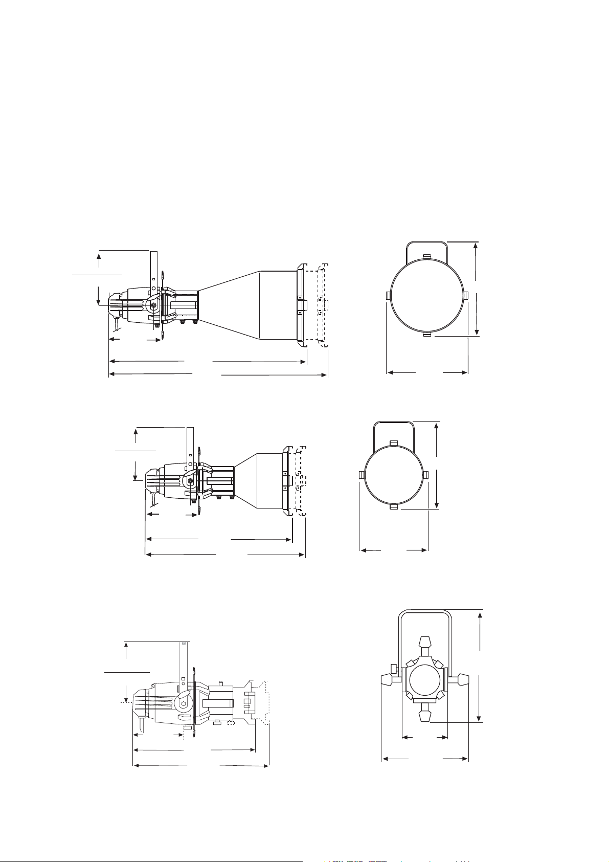
Specifications • Technische Daten
Spécifications • Especificaciones
5º CE Source Four
254mm max.
175mm min.
262mm
911mm
978mm
365mm
495mm
5° Weight: 8.6kg
5° Gewicht: 8,6kg
5° Poids: 8,6kg
5° Peso: 8,6kg
10º CE Source Four
254mm max.
175mm min.
262mm
692mm
19º, 26º, 36º, 50º CE Source Four
254mm max.
175mm min.
759mm
19º to 50º Weight: 6.3kg
19º bis 50º Gewicht: 6,3kg
19º à 50º Poids: 6,3kg
19° a 50° Peso: 6,3kg
314mm
432mm
10º Weight: 6.8kg
10º Gewicht: 6,8kg
10º Poids: 6,8kg
10º Peso: 6,8kg
426mm
222mm
546mm
613mm
4 CE Source Four
200mm
337mm
Page 5
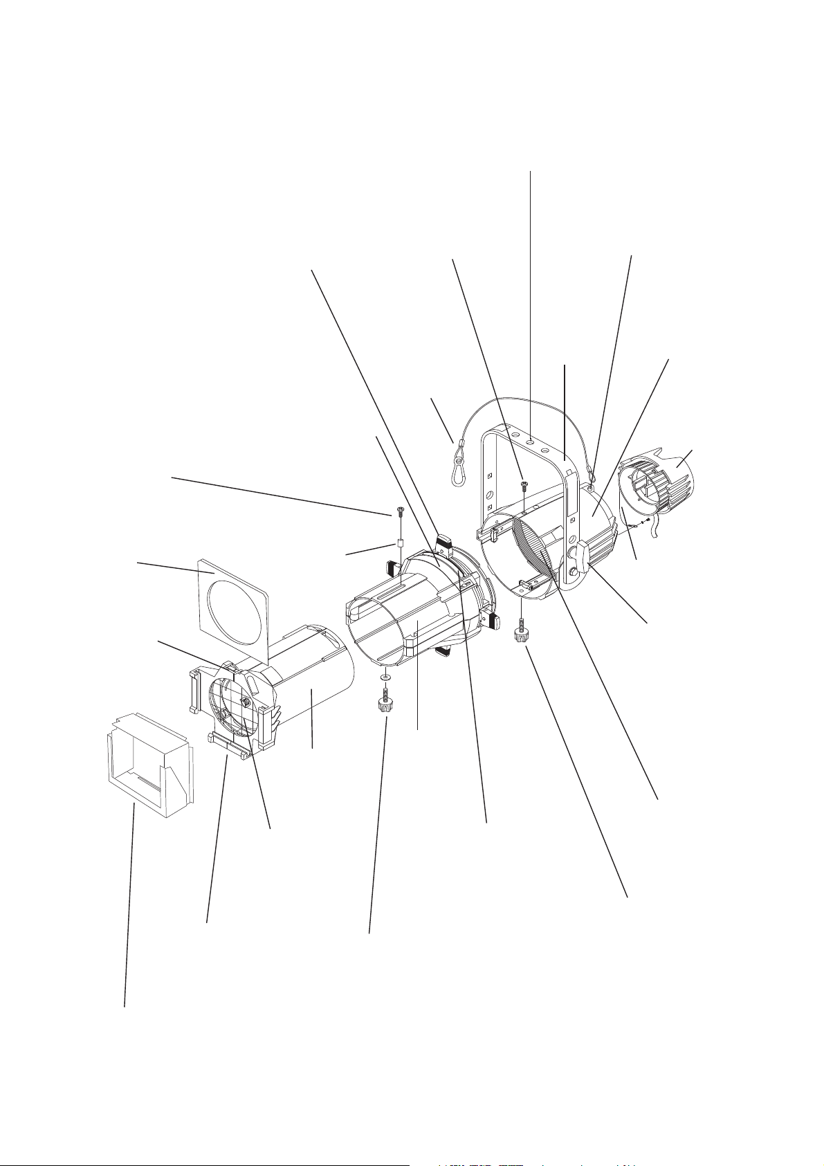
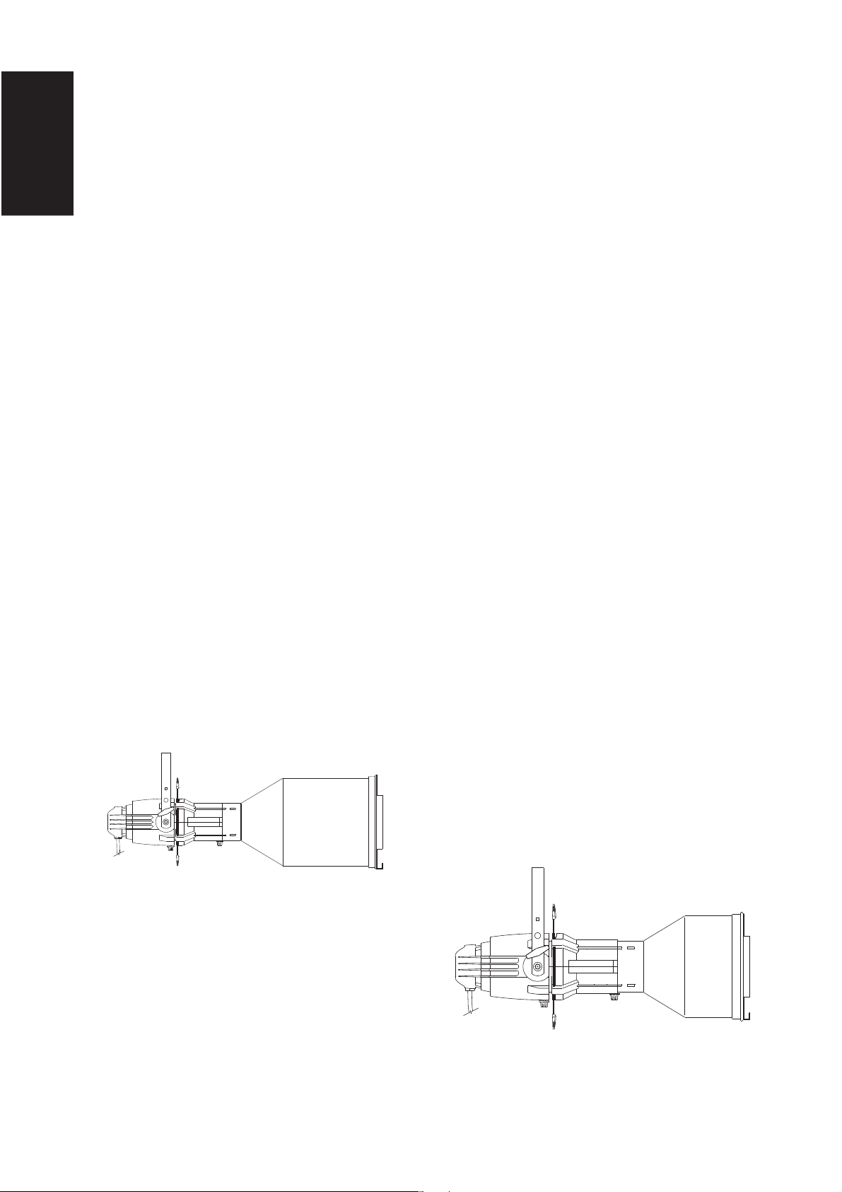
CE Source Four
Primary suspension yoke mounting holes
Hauptaufhängelöcher für Hängebügel
Trous de montage de la lyre de la suspension principale
Hoyos para el montaje de la lira de la suspensión primaria
Retainer bolt 1
Sicherungsschraube Nr.1
Vis de retenue 1
Tornillo de fijación 1
Colour frame
Farbrahmen
Porte-filtre
Portafiltros
Retainer bolt 2
Sicherungsschraube Nr. 2
Shutters
Blenden
Couteaux
Cuchillas
Drop-in iris slot
Einschubfach für Irisblende
Logement d'iris amovible
Ranura para el iris
Spacer
Abstandshalter
Pièce d'écartement
Pieza separadora
Vis de retenue 2
Tornillo de fijación 2
Safety cable
(model #400SC)
Sicherungsseil
(Modell #400SC)
Câble de sécurité
(modèle #400SC)
Cable de seguridad
(modelo #400SC)
Secondary suspension point
Befestigungsmöglichkeit für Sicherungsseil
Point de suspension secondaire
Punto secundario de suspensión
Yoke
Bügel
Lyre
Lira
Reflector housing
Reflektorgehäuse
Compartiment réflecteur
Cubierta del reflector
Lamp housing
Lampengehäuse
Compartiment lampe
Cubierta de la lámpara
Earth continuity cable
Erdungskabel
Cable de mise à la terre
Cable de tierra
Retaining clip
Sicherungsbügel
Clip de mantien
Clip de seguridad
Lens tube
Linsentubus
Tube de lentille
Tubo de lentes
Safety screen
Schutzgitter
Grille de protection
Rejilla de seguridad
Colour frame holder
Farbrahmenhalter
Glissière porte-filtre
Marco portafiltros
Gel frame holder extender (model #400GE)
Abstandhalter für Farbrahmen (Modell #400GE)
Rallonge du porte-filtre (modèle #400GE)
Extensión del marco portagelatinas (modelo 400GE)
Barrel
Basisgehäuse
Corps
Tubo
Pattern holder slot
Einschubfach für Gobohalter
Logement de porte-gobo
Ranura del portagobos
Beam focus knob
Fokussierknopf
Bouton de réglage du faisceau
Maneta de enfoque del haz
Yoke locking knob
Bügelfeststellschraube
Poignée de serrage de la lyre
Maneta para fijar la lira
Reflector
Reflektor
Réflecteur
Reflector
Barrel rotation knob
Knopf für Rotation des Basisgehäuses
Bouton de rotation du corps
Maneta de rotación del tubo
CE Source Four 5
Page 6

6 CE Source Four
Page 7
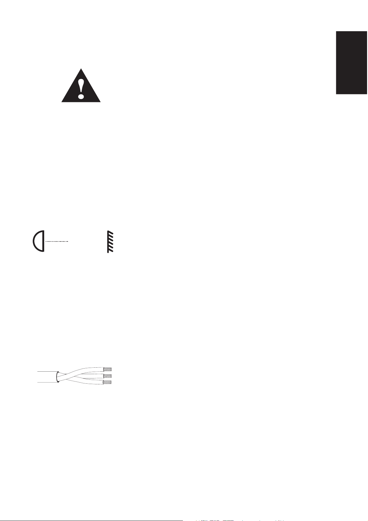
CE Source Four instructions
0.7m
Safety warnings
The CE Source Four high performance ellipsoidal spotlight is intended for
professional use only. Read entire
Please note the following safety warnings before use:
Do not mount the CE Source Four on or near a flammable surface.
Use the luminaire in dry locations only, where humidity does not exceed 90
percent. Luminaire is not intended for outdoor use.
Mount and support the luminaire only by the primary suspension yoke holes.
Suspend the luminaire from a hook clamp or a stand mount, using a securely
tightened steel bolt (up to 12 mm Ø), washer and locking nut.
In addition to primary suspension, attach a safety cable (Model 400SC) or
chain to the secondary suspension point on the luminaire (see page 5).
Open all four shutters completely before turning the luminaire on.
Always hang the CE Source Four with the colour frame retaining clip in the
locked position.
Always replace the lamp if it becomes damaged or thermally deformed.
Keep the luminaire at least 0.7 meters away from anything it is shining on.
Lighted objects at this distance or greater will not exceed 90ºC temperature
from projected light.
Disconnect the unit from power before all cleaning and maintenance.
User Manual
before using equipment.
English
t 180°c
Maximum ambient temperature: T
Maximum exterior surface temperature: T
A multilanguage label sheet is included with this manual. Affix the label of
the appropriate language over the existing warning label on the extension
yoke. Do not cover ETC trademark or CE mark.
=45°C
a
=200ºC
max
Wiring and power information
A plug of at least 2.5 amp (220/240V) rating should be attached to the
luminaire's mains lead. The wires in the mains lead are 1.5mm
coloured in accordance with the following code:
Green and Yellow: Earth
Blue: Neutral
Brown: Live
Warning: This luminaire must be earthed.
Current rating: 120V/5 amp maximum
240V/2.5 amp maximum
2
each and
Operating frequency: 50/60Hz
CE Source Four 7
Page 8
English
HPL lamps
HPL lamps are tungsten halogen lamps.
Important: Verify that the HPL lamp you use is suitable for the voltage at
your facility. 115-, 120-, 230-, and 240-volt HPL lamps are available.
Operating HPL lamps above their rated voltage reduces lamp life and can
cause premature lamp failure.
Warning: Do not use lamps other than the HPL in CE Source Four
luminaires. Use of lamps other than HPL will void CE safety conformity
and warranty.
edocpmaLsttaWstloVpmetroloCefildetarevA
032/575LPH575032K˚002,3ruoh004
Euro.
American
H575511K˚052,3ruoh003
042/575LPH575042K˚002,3ruoh004
511/573LPH573511K
X511/573LPH573511K˚050,3ruoh000,1
77/055LPH05577K˚052,3ruoh003
X77/055LPH05577K˚050,3ruoh000,2
511/575LP
X511/575LPH575511K˚050,3ruoh000,2
021/575LPH575021K˚052,3ruoh003
˚052,3ruoh003
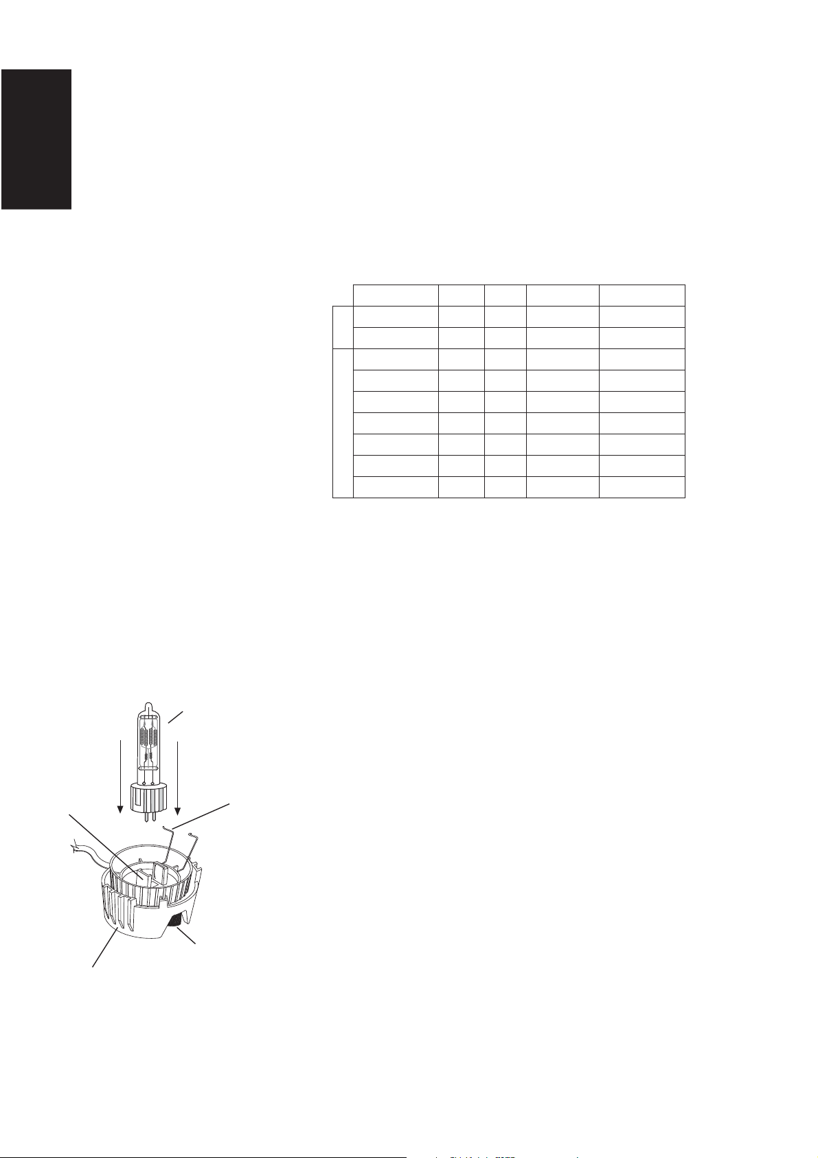
Figure 1
Lamp
retention
brackets
Lamp housing
HPL lamp
Lamp
retainers
Knurled bolt
Installing the HPL lamp
Important: The lamp must be installed before you use the luminaire.
Caution: Always replace the lamp if it becomes damaged or thermally
deformed.
1. Disconnect the unit from power before installing and replacing the lamp.
Warning: Let lamp cool before changing.
2. Loosen the knurled bolt on the back of the lamp housing and pull the
housing straight out.
3. Remove the HPL lamp from its box, holding it by the base.
Note: To avoid premature lamp failure, do not touch the lamp glass. If
you touch the lamp, clean it carefully with rubbing alcohol and a clean,
lint-free cloth before operation.
4. Line up the flat sides of the lamp base with the retention brackets on
either side of the socket. See figure 1.
5. Push down on the lamp base until the lamp seats firmly. (The top of the
lamp base will be even with the top edges of the retention brackets
when it is properly installed.)
Caution: Improperly installed lamps cause premature lamp failure and
socket problems.
6. Press lamp retainers down across lamp base and clip securely.
7. To reinstall the lamp housing, line up the side fins and the bolt hole, then
tighten the knurled bolt to secure the housing.
8 CE Source Four
Page 9
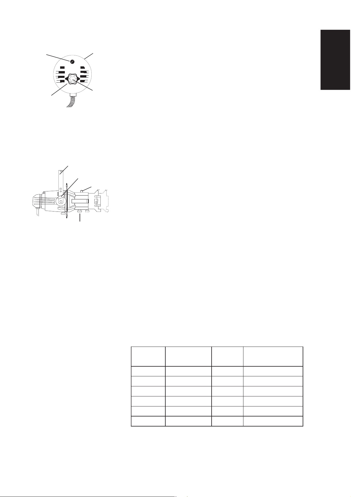
Figure 1
Knurled
bolt
Centre
adjustment
(outer knob)
Lamp
housing
Peak and flat
adjustment
(inner knob)
Aligning the lamp
Use the two concentric knobs on the rear of the lamp housing to align the
lamp. The outer knob centres the lamp within the reflector and locks it in
position; the inner knob fine tunes the field. See figure 1.
Important: Power must be on to align the lamp.
1. Unlock the outer knob by turning it anticlockwise one turn.
2. Gently push the outer knob from side to side and up and down until
the lamp is centred in the field.
3. Once the lamp is centred, tighten the outer knob to lock it in place.
4. Turn the inner knob right or left to adjust for optimum flat field.
English
Figure 2
Yoke
Yoke locking knob
Bolt and spacer
Beam focus knob
Focusing the beam
1. Loosen the beam focus knob on the underside of the barrel. See
figure 2.
2. Slide the lens tube forward or backward to achieve the desired beam
edge. (For optimum gel life, set soft focus by moving the lens as shown
on table below.)
3. Once the luminaire is focused, tighten the beam focus knob.
Gel notes
For best results, always use a high quality, high temperature color medium.
ETC does not guarantee performance with low temperature, saturated color
gels.
ETC's Source Four gel frame holder extender may help increase your gel life.
Contact ETC or your dealer for ordering information.
erutxiF
noisreV
5°
01 °
91 °
62 °
63 °
05 °
✔ = better gel life ✘ = worse gel life
CE Source Four 9
✔✔ ✔
✔✔ ✔
✔✔ ✘
sucoFtfoS
kcaBebuT
prahS
sucoF
sucoFtfoS
drawroFebuT
✘✔ ✔
✘✔ ✔
✘✔ ✔
Page 10
English
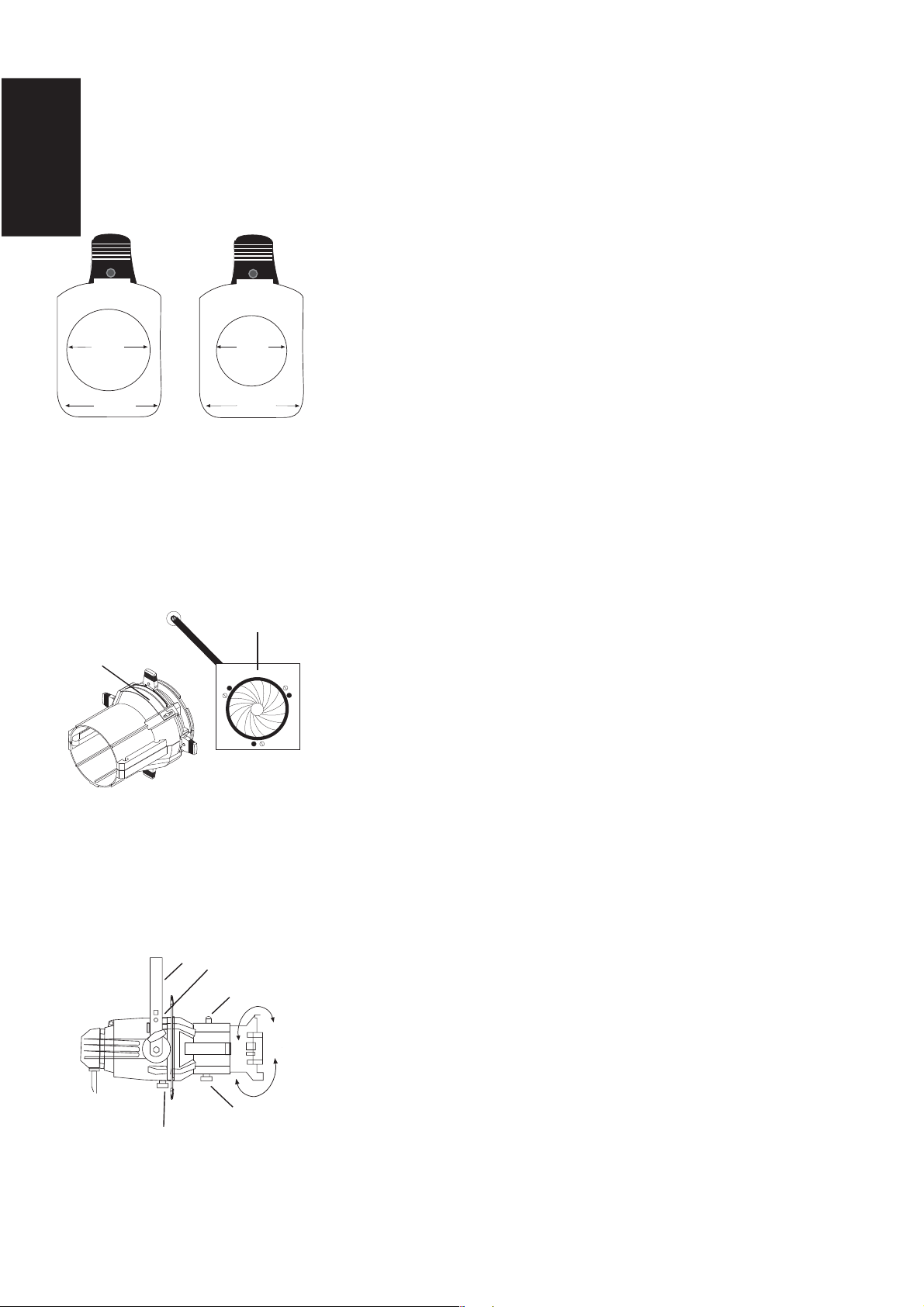
Figure 1
79mm
diameter
70mm
diameter
Shaping the beam
You may shape the beam with the shutters, a pattern, an optional drop-in
iris, and/or by rotating the barrel.
Pattern projection
The pattern holder slot is on the top side of the barrel, immediately in front
of the shutters. It accommodates A-size, B-size and glass pattern holders.
Use an optional donut (model #400DN) in the accessory holder to enhance
pattern projection. Donut diameter should be 64mm to 70mm for 19º
through 50º lenses.
94 mm
A-size pattern holder
for 8cm diameter
patterns
Figure 2
Drop-in iris slot
94 mm
B-size pattern holder
for 7cm and 6.3cm
diameter patterns
Iris
Drop-in iris slot
The drop-in iris slot is on the top side of the front barrel, immediately in front
of the pattern holder slot. It accommodates either a drop-in iris or a
motorized pattern device. When it is not in use, a small sheet metal cover
secured with two crosshead screws prevents light leakage and retains the
iris assembly. To install an iris, follow these steps:
1. Use a crosshead screwdriver to loosen the screws on the drop-in iris
slot cover. Do not remove the screws.
2. Slide the cover completely forward, exposing the slot.
3. Insert the iris or motorized pattern device. If you install an iris, the flat
side must be toward the shutters and the iris handle should extend out
of slot.
4. Slide the slot cover back toward the shutters until it meets the iris
handle. Leave enough space to move the iris handle. Tighten the
screws.
Figure 3
Yoke
Bolt 2
Bolt 1 and spacer
Beam focus knob
Barrel rotation knob
10 CE Source Four
Rotating the barrel assembly
1. Loosen the barrel rotation knob directly behind the shutters on the
underside of the reflector housing.
Caution: Do not remove the barrel rotation knob.
2. Rotate the barrel to the desired position (up to 25° in either direction
from centred position.)
3. Once the barrel is positioned, tighten the barrel rotation knob to lock it
into position.
Page 11
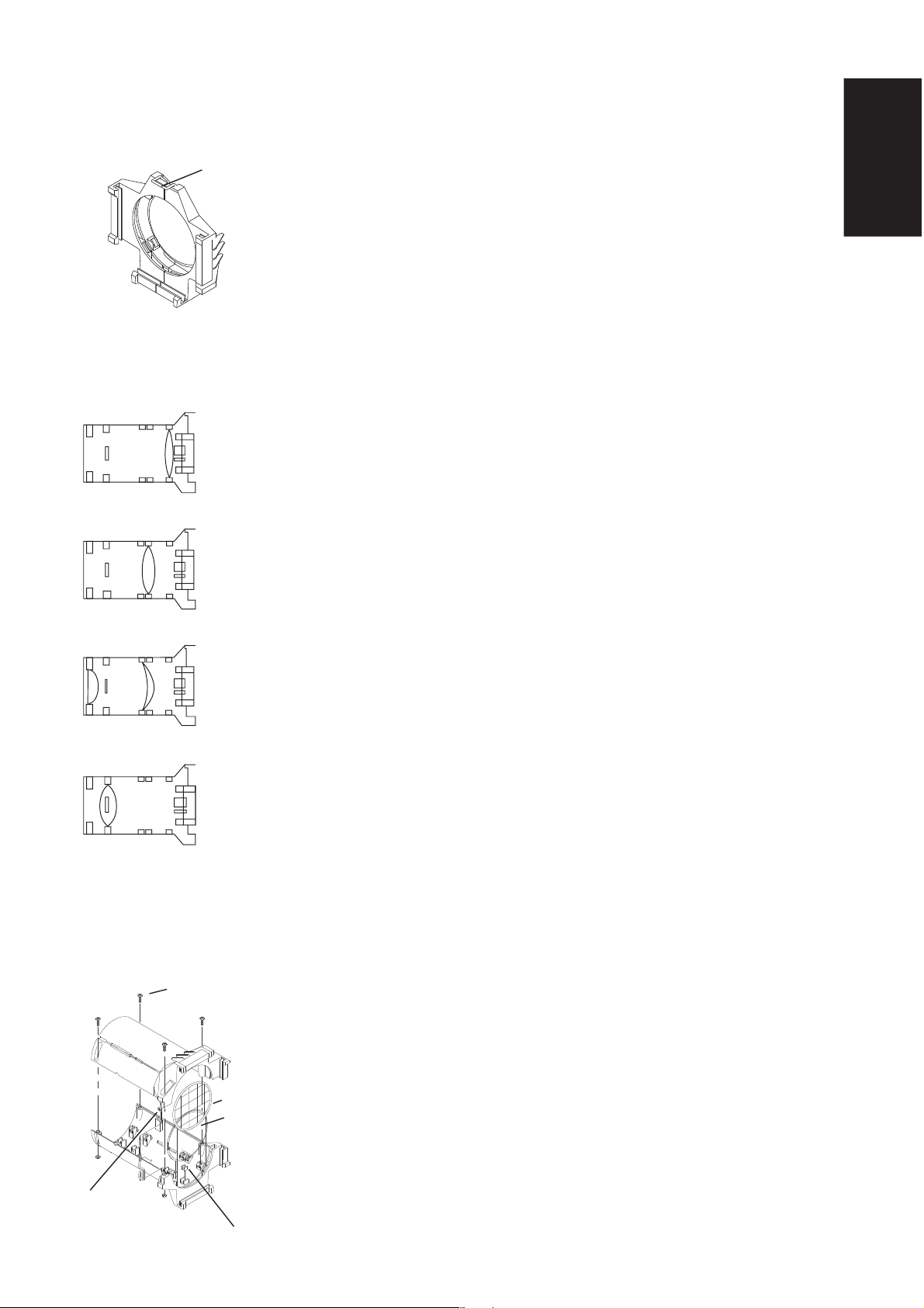
Colour frame retaining clip
Figure 1
Figure 2
19° (6x16)
Red dot ➝
26° (6x12)
Black dot➝
36° (6x9)
No dot
Retaining clip
in locked
position
The colour frame holder is equipped with a spring-loaded retaining clip that
prevents colour frames and accessories from falling out of the holder.
Important: Hang CE Source Four with the colour frame retaining clip in the
locked position before using the luminaire.
1. Release the retaining clip by pushing it sideways. The retaining clip will
pop open.
2. Insert the colour frame.
3. Press the retaining clip down until it locks into position.
Important: Use only CE Source Four colour frame.
Lenses
Note: Lens positions are not interchangeable within tube. Coloured dot on
lens must face forward. See figure 2.
Cleaning 19°, 26°, 36°, and 50° glass lenses
Caution: Change lenses if they become visibly damaged to the extent that
their effectiveness is impaired, for example, by cracks or deep scratches.
1. Disconnect the unit from power before cleaning lenses.
2. Remove the beam focus knob at the bottom of the barrel. Use a
crosshead screwdriver to remove retainer bolt 1 and spacer from the top
of the barrel. Remove the lens tube from the barrel.
3. Remove the four pairs of screws and nuts that hold the lens halves
together. Do not dislodge the two larger nuts resting in the wells of one
barrel half. See figure 3.
4. Lift out safety screen to access lens.
5. Dampen a clean, lint-free cloth with vinegar or household ammonia. You
may also use water, but it will leave spots that you may remove by
polishing the lens gently with a clean, dry cloth.
English
Warning: Never use glass and window cleaner or any abrasive material
to clean the lens. Glass and window cleaners will stain the lens surface.
Abrasive materials (such as steel wool) will damage the lens.
50° (4.5x6)
Yellow dot➝
Figure 3
Screw
Safety screen
Lens
Nut
Lens support pad
CE Source Four 11
6. Starting from the centre, gently wipe the lens. Do not dislodge the four
small rubber pads that mount lens in place.
7. Verify that dot painted on lens faces forward. Replace safety screen.
8. Put barrel back together, using retaining clip to guide and secure the
halves in place.
9. Replace screws and nuts.
10. Slide the lens tube back into the barrel with the colour frame retaining
clip on top. Replace beam focus knob and tighten bolt and spacer.
Page 12
English
Cleaning 5° and 10° polymer lenses
Remove dust with a blast of oil-free air. If this is not sufficient, follow the
instructions below. You will need a crosshead screwdriver.
Caution: Handle polymer lenses by their edges only. Never rub anything dry
on a polymer lens. Do not use glass and window cleaners on the lens.
Caution: Change lenses if they become visibly damaged or deformed to the
extent that their effectiveness is impaired, for example, by cracks or deep
scratches.
1. Disconnect unit from power before cleaning lens.
2. Remove the beam focus knob. Gently pull the lens tube out of the
barrel.
3. Use a crosshead screwdriver to remove the brackets that hold the lens
in. Remove the lens from the lens tube.
4. Dip lens in clean alcohol/water mixture (ten percent alcohol).
5. Use a moistened, soft nylon bristle brush. Wash the smooth side of the
lens with gentle, straight strokes.
6. Use the same moistened brush to clean the ridged side, following the
ridges, without hand pressure.
7. Dip lens in clean alcohol/water mixture (ten percent alcohol).
8. Use air gun to dry the smooth surface.
9. Use air gun to dry the ridged surface. Use air stream to move liquid
away from you. Continue to remove as much liquid as possible.
10. Inspect the lens for dirt. Repeat the entire process as necessary.
11. Set the lens back in the lens tube with the ridged side facing the front of
the tube. Replace the brackets.
12. Slide the lens tube back into the barrel with colour frame retainer on top.
Replace beam focus knob and tighten bolt and spacer.
5º
10º
12 CE Source Four
Page 13

Cleaning the reflector
Figure 1
Retainer bolt 2
Barrel rotation knob
Lamp housing
Reflector housing
Reflector
Remove the lens tube. Remove dust from the reflector with a blast of oilfree air into the reflector area. If this is not sufficient, follow the instructions
below. You will need a crosshead screwdriver to complete this procedure.
Warning: Disconnect the unit from power before cleaning reflector.
Warning: Do not use glass and window cleaners on the reflector.
Chemicals in these cleaners will stain the reflector.
1. Remove the lamp housing (see
2. Unscrew and remove the barrel rotation knob located at the bottom of
the barrel. Use a crosshead screwdriver to undo retainer bolt 2, located
at the top of the reflector housing.
3. Grasp the barrel and rotate it 45° in either direction. Carefully remove
the barrel from the reflector housing and set it aside.
4. Dampen a clean, lint-free cloth with alcohol or distilled water. (Alcohol is
recommended.)
5. Gently wipe the reflector.
6. Insert the barrel into the reflector housing with the pattern slot on top.
(Line up the triangles on both parts.)
7 Pressing in gently, rotate the barrel 45° clockwise until it settles into
position. Rotate the barrel anticlockwise 45°. The barrel should be firmly
attached and the triangles should line up again.
8. Replace the barrel rotation knob and tighten the bolt.
Installing the HPL Lamp
, page 8).
English
Accessories
Pattern holder, A-size ...................................... 400PH-A
Pattern holder, B-size ...................................... 400PH-B
Pattern holder, glass ........................................400PH-G
6.25" (15.875cm) donut for 19-50º ................... 400DN
Donut for 10º ................................................... 410DN
Donut for 5º ..................................................... 405DN
6.25" (15.875cm) snoot for 19-50º ...................400SN
6.25" (15.875cm) colour frame for 19-50º ........400CF
12" (30.48cm) colour frame for 10º ..................410CF
14" (35.56cm) colour frame for 5º .................... 405CF
Drop-in iris assembly .......................................400RS
30" (76.2cm) safety cable, black ...................... 400SC
C-clamp ...........................................................400CC
50º lens tube ...................................................400LT-50
36º lens tube ...................................................400LT-36
26º lens tube ...................................................400LT-26
19º lens tube ...................................................400LT-19
10º lens tube ...................................................400LT-10
5º lens tube .....................................................400LT-5
Fixture body (single clutch) ..............................400FB
Fixture body (double clutch) ............................ 405FB
Gel frame holder extender ..............................400GE
CE Source Four 13
Page 14

English
14 CE Source Four
Page 15

CE Source Four Bedienungsanleitung
Sicherheitshinweise
Der CE Source Four ist ein Ellipsenscheinwerfer mit hoher Leistung, der nur
durch Fachpersonal bedient werden sollte. Bitte lesen Sie vor dem Einsatz
die Gebrauchsanleitung. Beachten Sie die folgenden Sicherheitshinweise:
Befestigen Sie den CE Source Four nicht an oder in der Nähe von
entzündbaren Oberflächen.
Den Scheinwerfer nur in trockenen Räumen einsetzen, wo die
Luftfeuchtigkeit unter 90% liegt. Der Scheinwerfer ist nicht für den
Außeneinsatz geeignet
Den Scheinwerfer nur mit Hilfe der Hauptaufhängelöcher des Bügels montieren
und sichern. Den Scheinwerfer an einer Hakenklemme oder an
einem Stativ mit einer festgedrehten Stahlschraube (bis zu 12 mm
Durchmesser), U-Scheibe und Sperrmutter befestigen.
Stellen Sie sicher, daß am Scheinwerfer neben der Hauptbefestigung auch ein
Sicherheitsseil (Modell #400SC) an der Befestigungsmöglichkeit für das
Sicherungsseil angebracht ist. Siehe Seite 5.
Die vier Blenden müssen vor dem Einschalten des Scheinwerfers vollständig
geöffnet sein.
.
Deutsch
0,7m
Der Sicherungsbügel des Farbrahmens muß beim Aufhängen des CE Source
Four immer in Verschlußposition sein.
Lampen die beschädigt oder durch Hitzeeinwirkung verformt sind, müssen
umgehend ersetzt werden.
Der Scheinwerfer sollte mindestens 0,7m von angestrahlten Gegenständen
entfernt sein. Bei Einhaltung dieses oder eines größeren Abstandes, erwärmen
sich die angestrahlten Gegenstände durch den Lichtstrahl bis max. 90º C.
Der Scheinwerfer muß vor dem Reinigen oder vor Wartungsarbeiten allpolig vom
Netz getrennt werden.
Maximale Raumtemperatur: T
Maximale Temperatur der Außenoberflächen: T
Dieser Anleitung liegt ein Blatt mit Etiketten in verschiedenen Sprachen bei.
Kleben Sie das Etikett der entsprechenden Sprache über den angebrachten
Warnungsaufkleber am Haltebügel. Die ETC Marke und die CE
Marke nicht überkleben.
=45° C
a
=200° C
max
Hinweise für den Anschluß ans Netz
Für den Netzanschluß des Scheinwerfers sollte ein Stecker mit einer
Mindestbelastbarkeit von 2,5A (220/240V) verwendet werden. Die Drähte im
Netzanschlußkabel haben einen Durchmesser von 1,5mm und sind
entsprechend den folgenden Farben kodiert:
Grün und gelb: Schutzleiter
t 180°c
CE Source Four 15
Blau: Nulleiter
Braun: Stromführend
Achtung: Dieser Scheinwerfer muß geerdet werden.
Stromversorgung: maximal 120V/5A, maximal 240V/2,5A
Betriebsfrequenz: 50/60Hz
Page 16

Deutsch
HPL Lampen
HPL Lampen sind Tungstenhalogenlampen
Wichtig: Vergewissern Sie sich, daß die HPL Lampe die Sie verwenden, für
die Spannung in Ihrem Gebäude geeignet ist. Es sind 115V, 120V, 230V und
240V HPL Lampen lieferbar. Die Verwendung von HPL Lampen mit
Spannungen die über ihrem Richtwert liegen, verkürzt die Lebensdauer der
Lampe und kann zu frühzeitigem Versagen der Lampe führen.
Achtung: Für den CE Source Four Scheinwerfer nur HPL Lampen
verwenden. Wenn keine HPL-Lampen eingesetzt werden, entspricht der
Scheinwerfer nicht mehr den CE Sicherheitsnormen und es erlischt die
Garantie.
edocnepmaLttaWtloVrutarepmetbraFreuadsnebeLerelttiM
032/575LPH575032K˚002.3nednutS004
europ.
H05577K˚050.3nednutS000.2
amerikanische
042/575LPH575042K˚002.3nednut
511/573LPH573511K˚052.3nednutS003
X511/573LPH573511K˚050.3nednutS000.1
77/055LPH05577K˚052.3nednutS003
X77/055LP
511/575LPH575511K˚052.3nednutS003
X511/575LPH575511K˚050.3nednutS000.2
021/575LPH575021K˚052.
3nednutS003
S004
Abbildung 1
Lampenhalter
Lampengehäuse
HPL Lampe
Lampenhalterklammern
Rändelschraube
Einbau der HPL Lampe
Wichtig: Die Lampe muß vor Inbetriebnahme des Scheinwerfers installiert
werden.
Achtung: Lampen, die beschädigt oder durch Hitzeeinwirkung verformt
sind, müssen umgehend ersetzt werden.
1. Der Scheinwerfer muß vor Einbau und Austausch der Lampe vom Netz
getrennt werden.
Achtung: Die Lampe vor dem Auswechseln abkühlen lassen.
2. Die Rändelschraube an der Rückseite des Lampengehäuses lockern,
und das Gehäuse nach hinten abziehen.
3. Die HPL Lampe am Sockel festhalten und aus der Verpackung nehmen.
Hinweis: Um frühzeitiges Versagen der Lampe zu vermeiden, sollte das
Glas der Lampe nicht berührt werden. Sollte es doch zu einer Berührung
des Glases kommen, muß die Lampe vor Inbetriebnahme vorsichtig mit
Spiritus und einem fusselfreien Tuch saubergemacht werden.
4. Richten Sie die flachen Seiten des Lampensockels an den beiden
Lampensockelhaltern aus. Siehe Abbildung 1.
5. Am Lampensockel nach unten drücken, bis die Lampe gut sitzt. (Wenn
die Lampe richtig installiert ist, ist die Oberkante des Lampensockels
bündig mit der Oberkante der Fassung).
Achtung: Falsch installierte Lampen führen zu frühzeitigem Versagen
der Lampe und zu Problemen mit dem Sockel.
6. Die Lampenhalterklammern über den Sockel legen und sichern.
7. Das Lampengehäuse zum Wiedereinbau an den Seitenfinnen und am
Loch für die Schraube ausrichten, und dann die Rändelschraube
festdrehen bis das Gehäuse sicher sitzt.
16 CE Source Four
Page 17

Abbildung1
Rändelschraube
Zentrierung
(Äußerer Knopf)
Lampengehäuse
Mitten- und
flächenoptimierte
Einstellung
(Innerer Knopf)
Einstellen der Lampe
Die zwei konzentrischen Knöpfe an der Rückwand des Lampengehäuses
dienen dem Einstellen der Lampe. Der äußere Knopf zentriert die Lampe
innerhalb des Reflektors und verriegelt sie. Mit dem inneren Knopf wird das
Feld feinabgestimmt. Siehe Abbildung 1.
Wichtig: Die Lampe muß zum Einstellen eingeschaltet sein.
1. Entriegeln Sie den äußeren Knopf, indem Sie ihn eine Drehung gegen
den Uhrzeigersinn drehen.
2. Den äußeren Knopf so verschieben, daß die Lampe im Feld zentriert ist.
3. Wenn die Lampe zentriert ist, den äußeren Knopf festdrehen, um die
Lampe zu verriegeln.
4. Zur optimalen Flächeneinstellung den inneren Knopf nach rechts und
links drehen.
Deutsch
Abbildung 2
Bügelfeststellschraube
Bügel
Fokussierknopf
Schraube und
Abstandshalter
Fokussierung des Lichtstrahls
1. Den Fokussierknopf an der Unterseite des Basisgehäuses lösen. Siehe
Abbildung 2.
2. Den Linsentubus vorwärts oder rückwärts schieben, bis die gewünschte
Schärfeeinstellung erreicht ist. (Für optimale Lebensdauer des
Farbfilters, Defokussierung entsprechend der Aufstellung wählen).
3. Wenn der Scheinwerfer fokussiert ist, den Fokussierknopf festdrehen.
Hinweise für Farbfilter
Für beste Ergebnisse empfehlen wir, nur hitzebeständige Qualitätsfarbfilter
zu verwenden. Bei Verwendung von kräftigen Farbfiltern, die nicht
hitzebeständig sind, übernimmt ETC keine Garantie für die Leistung.
Der Source Four Abstandhalter für Farbrahmen kann die Lebensdauer des
Farbfilters verlängern. Zur Bestellung nehmen Sie bitte Kontakt mit ETC oder
Ihrem Händler auf.
lledoM
5°
01 °
91 °
62 °
63 °
05 °
✔ = längere Lebensdauer des Farbfilters ✘ = kürzere Lebensdauer des Farbfilters
CE Source Four 17
✔✔✔
✔✔✔
✘✔✔
✘✔✔
✔✔ ✘
✘✔✔
gnureissukofeD
netnihsubuT
efrahcS
gnureissukoF
gnureissukofeD
enroVsubuT
Page 18

Abbildung 1
Deutsch
Abbildung 2
Einschubfach für
Irisblende
Durchmesser
79 mm
94 mm
Gobohalter
der Größe A
für Gobos
mit 8 cm
Durchmesser
Durchmesser
70 mm
94 mm
Gobohalter der
Größe B für
Gobos mit 7 cm
und 6,3 cm
Durchmesser
Irisblende
Lichtstrahlbegrenzung
Der Strahl kann mit Blendeschiebern, einem Gobo, einer (optionalen)
einschiebbaren Irisblende, und/oder durch Drehen des Tubus geformt
werden.
Projektion von Gobos
Das Einschubfach für Gobohalter befindet sich an der Oberseite des
Basisgehäuses, direkt vor den Blenden. In das Einschubfach passen
Gobohalter der Größe A und B, sowie Glasgobohalter.
Es besteht die Möglichkeit durch Verwendung einer Lochblende (Modell
#400DN) im Zubehörhalter die Projektion von Gobos zu verbessern. Für 19°
bis 50° Linsen sollte der Durchmesser der Lochblende mindestens 64mm
bis 70mm betragen.
Einschubfach für Irisblende
Das Einschubfach für die Irisblende befindet sich an der Oberseite des
vorderen Basisgehäuses, direkt vor dem Einschubfach für Gobohalter. Es
kann entweder eine Einschubirisblende oder ein Gobo Rotator verwendet
werden. Wenn das Einschubfach nicht benötigt wird, kann es mit einem
kleinen Blechdeckel und zwei Kreuzschlitzschrauben abgedeckt werden, so
daß kein Licht austritt und den Irisblendenrahmen festhält. Eine Irisblende
wird folgendermaßen installiert:
1. Mit einem Kreuzschlitzschraubenzieher die Schrauben des Deckels des
Einschubfaches für die Irisblende lösen. Die Schrauben nicht ganz
herausdrehen.
2. Den Deckel ganz nach vorne schieben und damit die Öffnung freilegen.
3. Die Irisblende oder den Gobo Rotator einstecken. Bei Installation einer
Irisblende muß die flache Seite auf die Blenden zeigen, und der Griff der
Irisblende sollte aus dem Einschubfach herausragen.
4. Den Deckel in Richtung der Blenden schieben, bis er den Griff der
Irisblende berührt. Genügend Raum lassen, so daß der Griff der
Irisblende bewegt werden kann. Danach die Schrauben festdrehen.
Rotation des Grundgehäuses
1. Lösen Sie den Knopf für die Rotation des Basisgehäuses, der direkt
hinter den Blenden an der Unterseite des Reflektorgehäuses sitzt.
Vorsicht: Den Knopf für die Rotation des Basisgehäuses nicht ganz
Abbildung 3
Schraube Nr. 2
Bügel
Knopf für Rotation
des Basisgehäuses
18 CE Source Four
Schraube Nr. 1 und
Abstandshalter
Fokussierknopf
herausschrauben.
2. Das Gehäuse in die gewünschte Position drehen (bis zu 25o in beide
Richtungen von der Mittelposition ausgehend).
3. Wenn das Gehäuse eingestellt ist, den Knopf für die Rotation des
Basisgehäuses festdrehen, um das Gehäuse in dieser Position zu
arretieren.
Page 19

Abbildung 1
Sicherungsbügel in
geschlossener Position
Sicherungsbügel des Farbrahmens
Der Farbrahmenhalter ist mit einem gefederten Sicherungsbügel
ausgestattet, der verhindert, daß Farbrahmen und Zubehör aus dem Rahmen
herausfallen können.
Wichtig: Der CE Source Four sollte vor Inbetriebnahme mit dem
Sicherungsbügel in geschlossener Position aufgehängt werden.
1. Den Sicherungsbügel öffnen. Wenn er seitlich gedrückt wird, springt
er auf.
2. Den Farbrahmen hineinstecken.
3. Den Sicherungsbügel
Wichtig: Nur CE Source Four Farbrahmen verwenden.
nach unten drücken, bis er einrastet.
Abbildung 2
19° (6x16)
Roter Punkt➝
26° (6x12)
Schwarzer
Punkt➝
36° (6x9)
Kein Punkt
50° (4.5x6)
Gelber Punkt➝
Deutsch
Linsen
Plazierung der Linsen
Anmerkung: Die Anordnung der Linsen im Tubus ist nicht auswechselbar.
Der farbige Punkt an der Linse muß nach vorne zeigen.
Säuberung von 19º,26º,36º und 50º Glaslinsen
Vorsicht: Linsen die sichtbare Schäden haben, wie zum Beispiel Risse oder
tiefe Kratzer, und deren Leistungsfähigkeit dadurch eingeschränkt ist,
müssen ausgetauscht werden.
1. Der Scheinwerfer muß vor dem Reinigen der Linsen vom Netz getrennt
werden.
2. Den Fokussierknopf an der Unterseite des Basisgehäuses entfernen.
Mit einem Kreuzschlitzschraubenzieher Sicherungsschraube Nr. 1 mit
Abstandshalter von der Oberseite des Gehäuses entfernen. Danach den
Linsentubus aus dem Gehäuse herausziehen.
3. Die vier Schrauben- und Mutternpaare, die die Linsenhälften
zusammenhalten, entfernen. Die zwei größeren Muttern, die in
Vertiefungen in der einen Basisgehäusehälfte liegen, nicht entfernen.
Siehe Abbildung 3.
4. Um die Linsen herauszunehmen, muß das Schutzgitter entfernt werden.
5. Ein sauberes fusselfreies Tuch mit Essig oder verdünntem Ammoniak
befeuchten. Es kann auch Wasser verwendet werden, aber es hinterläßt
Flecken, die man entfernen kann, indem man die Linse leicht mit einem
sauberen trockenen Tuch poliert.
Warnung: Die Linsen dürfen nie mit Glas- und Fensterreinigungsmittel
oder mit scheuernden Mitteln gereinigt werden. Glas- und
Abbildung 3
Schaube
Schutzgitter
Linse
Mutter
CE Source Four 19
Gummilinsenschutz
Fensterreinigungsmittel hinterlassen Flecken auf der Linsenoberfläche.
Scheuernde Mittel (wie zum Beispiel Stahlwolle) beschädigen die Linse.
6. Von der Mitte ausgehend, die Linse sanft reinigen. Die vier kleinen
Gummikissen, die die Linse festhalten, nicht entfernen.
7. Versichern Sie sich, daß der Farbpunkt auf der Linse nach vorne zeigt.
Das Schutzgitter wieder einsetzen.
8. Das Basisgehäuse wieder zusammensetzen. Mit Hilfe des
Sicherungsbügels die Hälften aneinander ausrichten und befestigen.
9. Schrauben und Muttern wieder einsetzen.
10. Den Linsentubus zurück ins Gehäuse schieben, so daß der
Sicherungsbügel des Farbrahmens oben ist. Den Fokussierknopf
einsetzen und die Sicherungsschraube mit Abstandshalter festdrehen.
Page 20

Säuberung von 5º und 10º Polymerlinsen
Den Staub mit einem Strahl ölfreier Preßluft entfernen. Sollte das nicht
genügen, dann den nachstehenden Anweisungen folgen. Sie benötigen dazu
einen Kreuzschlitzschraubenzieher.
Vorsicht: Polymerlinsen nur am Rand anfassen. Die Polymerlinse nie mit
trockenen Materialien reiben. Der Linse darf nicht mit Glas- und
Fensterreinigungsmittel in Berührung kommen.
Deutsch
Vorsicht: Linsen, die sichtbare Schäden haben, wie zum Beispiel Risse oder
tiefe Kratzer und deren Leistungsfähigkeit dadurch eingeschränkt ist,
müssen ausgetauscht werden.
1. Der Scheinwerfer muß vor dem Reinigen der Linse vom Netz getrennt
werden.
2. Den Fokussierknopf entfernen. Danach den Linsentubus vorsichtig aus
dem Gehäuse herausziehen.
3. Mit einem Kreuzschlitzschraubenzieher die Halter, mit denen die Linse
befestigt ist, entfernen. Die Linse aus dem Linsentubus herausnehmen.
4. Die Linse in eine Mischung aus Spiritus und sauberem Wasser (10%
Spiritus) tauchen.
5. Die glatte Seite der Linse mit einer weichen, feuchten Nylonbürste in
geradliniger Bewegung vorsichtig waschen.
6. Mit der gleichen feuchten Bürste die gerippte Seite waschen und dabei
den Rippen ohne Handdruck folgen.
7. Die Linse in eine Mischung aus Spiritus und sauberem Wasser (10%
Spiritus) tauchen.
8. Die glatte Seite mit Preßluft trocknen.
9. Die gerippte Seite mit Preßluft trocknen. Treiben Sie mit dem Luftstrom
das Wasser von sich weg. Soviel Flüssigkeit wie möglich wegblasen.
10. Die Linse auf Schmutz untersuchen. Notfalls den Reinigungsvorgang
wiederholen.
11. Die Linse wieder in den Linsentubus einsetzen, so daß die gerippte
Seite in Richtung Vorderseite des Gehäuses zeigt. Die Halter einsetzen.
12. Den Linsentubus wieder in das Gehäuse einschieben, so daß der
Farbrahmenhalter nach oben zeigt. Den Fokussierknopf einsetzen und
die Sicherungsschraube mit Abstandshalter festdrehen.
5º
10º
20 CE Source Four
Page 21

Abbildung 1
Sicherungsschraube Nr. 1
Lampengehäuse
Säuberung des Reflektors
Den Linsentubus entfernen. Den Reflektor mit einem Strahl ölfreier Preßluft,
der in den Reflektor gerichtet ist, vom Staub befreien. Sollte das nicht
genügen, dann bitte den nachstehenden Anweisungen folgen. Sie benötigen
dazu einen Kreuzschlitzschraubenzieher.
Warnung: Der Scheinwerfer muß vor dem Reinigen des Reflektors vom Netz
getrennt werden.
Warnung: Der Reflektor darf nicht mit Glas- und Fensterreinigungsmittel in
Berührung kommen, weil Chemikalien, die in diesen Reinigungsmitteln
enthalten sind, am Reflektor Flecken verursachen.
Reflektorgehäuse
Reflektor
Knopf für Rotation des
Basisgehäuses
1. Das Lampengehäuse entfernen (siehe
Seite 16).
2. Den Knopf für die Rotation des Basisgehäuses an der Gehäuseunterseite herausschrauben. Mit einem Kreuzschlitzschraubenzieher
die Sicherungsschraube Nr. 2 lösen, die sich an der Oberseite des
Reflektorgehäuses befindet.
3. Das Gehäuse gut festhalten und um 45
drehen. Das Gehäuse vorsichtig aus dem Reflektorgehäuse
herausziehen.
4. Ein sauberes fusselfreies Tuch mit Spiritus oder destilliertem Wasser
befeuchten. (Wir empfehlen Spiritus.)
5. Den Reflektor sanft ausreiben.
6. Das Gehäuse wieder in das Reflektorgehäuse einführen, so daß das
Goboeinschubfach oben ist. (Die Dreiecke an beiden Teilen müssen sich
gegenüberstehen.)
7. Das Gehäuse mit sanftem Druck hineinschieben und um 45
Uhrzeigersinn drehen bis, es in Position ist. Dann das Gehäuse gegen
den Uhrzeigersinn um 45
Dreiecke sollten sich wieder gegenüberstehen.
8. Den Knopf für die Rotation des Basisgehäuses wieder anbringen und die
Sicherungsschraube festdrehen.
o
drehen. Das Gehäuse sollte festsitzen und die
Einbau der HPL Lampe,
o
entweder nach rechts oder links
o
im
Deutsch
Zubehör
Gobohalter, Größe A .......................................400PH-A
Gobohalter, Größe B .......................................400PH-B
Gobohalter, Glas ..............................................400PH-G
6.25" (15,875cm) Donut für 5° ......................... 400DN
Donut für 10° ................................................... 410DN
Donut für 5° ..................................................... 405DN
6.25" (15,875cm) Tube für 19-50° .................... 400SN
6.25" (15,875cm) Farbrahmen für 19-50° ........ 400CF
12" (30,48cm) Farbrahmen für 10° .................. 410CF
14" (35,56cm) Farbrahmen für 5° .................... 405CF
Rahmen für Einschubblende ........................... 400RS
30" (76,2cm) Sicherungsseil, schwarz ............. 400SC
C-Klemme ........................................................ 400CC
36° Linsentubus .............................................. 400LT-36
50° Linsentubus .............................................. 400LT-50
26° Linsentubus .............................................. 400LT-26
19° Linsentubus .............................................. 400LT-19
10° Linsentubus .............................................. 400LT-10
5° Linsentubus ................................................ 400LT-5
Scheinwerfergehäuse (einfache Befestigung) 400FB
Scheinwerfergehäuse (doppelte Befestigung) 405FB
Abstandhalter für Farbrahmen .........................400GE
CE Source Four 21
Page 22

Deutsch
22 CE Source Four
Page 23

Mode d'emploi CE Source Four
Avertissements de sécurité
Le projecteur à faisceau concentré ellipsoïdal à haute performance CE
Source Four est uniquement destiné à une utilisation professionnelle. Lire la
notice d’utilisation en entier avant d’utiliser cet équipement. Prendre
connaissance des avertissements de sécurité suivants avant d’utiliser cet
équipement:
Ne pas installer le CE Source Four sur ou à côté d’une surface inflammable.
Utiliser le luminaire seulement dans des lieux secs, où l’humidité ne dépasse
pas 90 pour cent. Ce luminaire n’est pas conçu pour être utilisé à l’extérieur.
Installer et supporter le luminaire seulement par les trous de la lyre de
suspension principale. Suspendre le luminaire à un crochet ou à un support,
en utilisant un boulon d’acier (jusqu’à 12mm Ø), une rondelle et un contreécrou bien serrés.
Outre la suspension principale, attacher un câble de sécurité (modèle
#400SC) ou une chaîne au point de suspension secondaire du luminaire
(voir la page 5).
Ouvrir complètement les quatre couteaux avant d’allumer le luminaire.
Français
0,7m
Toujours s’assurer que le clip de maintien du porte-filtre est bien verrouillé
avant d’accrocher le CE Source Four.
Toujours remplacer une lampe endommagée ou déformée sous l’effet de la
chaleur.
Garder le luminaire à 0,7 mètres au moins de l’objet sur lequel il est pointé.
La température des objets illuminés placés à cette distance ou plus loin ne
dépassera pas 90ºC due à la lumière projetée.
Débrancher l’unité avant tout nettoyage ou entretien.
Température ambiante maximum: T
Température maximum de la surface extérieure: T
Une feuille d’étiquettes de sécurité en plusieurs langues est jointe à ce
manuel. Coller l’étiquette dans la langue appropriée par-dessus celle qui se
trouve sur la lyre de rallonge. Ne pas couvrir la marque déposée ETC ni la
marque CE.
=45°C
a
=200°C
max
Câblage électrique
Monter une fiche d’au moins 2,5A (220/240V) au câble d’alimentation du
luminaire. Les fils du câble d'alimentation font chacun 1,5mm
colorés selon le code suivant:
Vert et jaune: Terre
2
et sont
t 180°c
CE Source Four 23
Bleu: Neutre
Marron: Sous tension
Attention:
Puissance électrique: 120V/5 amp maximum
Fréquence de service: 50/60Hz
Cet luminaire doit être mis à la terre.
240V/2,5 amp maximum
Page 24

Français
Lampes HPL
Les lampes HPL sont des lampes halogènes tungstène.
Attention: Vérifiez que la lampe HPL que vous utilisez est compatible avec
le voltage de vos installations. Des lampes HPL de 115V, 120V, 230V et
240V sont disponibles. L’utilisation d’une lampe HPL au-dessus de son
voltage nominal réduit sa durée de vie et peut provoquer son arrêt de
fonctionnement prématuré.
Attention: N'utiliser que des lampes HPL dans les luminaires CE Source
Four. L'utilisation de toute autre lampe qu'une lampe HPL annule la
conformité et la garantie de sécurité du CE.
epmalededoCsttaWstloVrueluoc.pmeT.yomeivedeéruD
032/575LPH575032K˚002.3serueh004
euro.
américaines
042/575LPH575042K˚002.3serueh004
51
1/573LPH573511K˚052.3serueh003
X511/573LPH573511K˚050.3serueh000.1
77/055LPH05577K˚052.3serueh003
X77/055LPH05577K˚050.
511/575LPH575511K˚052.3serueh003
X511/575LPH575511K˚050.3serueh000.2
021/575LPH575021K˚052.3serueh003
3serueh000.2
Figure 1
Attaches de la
lampe
Compartiment
lampe
Lampe HPL
Dispositif
de retenue
de la lampe
Boulon moleté
Installation de la lampe HPL
NB: Installez la lampe avant d’utiliser le luminaire.
Attention: Toujours remplacer une lampe endommagée ou déformée sous
l’effet de la chaleur.
1. Débrancher l’unité avant d’installer et de remplacer la lampe.
Attention: Laisser refroidir la lampe avant de la changer
2. Desserrer le boulon moleté au dos du compartiment lampe et retirer le
compartiment du luminaire.
3. Sortir la lampe HPL de sa boîte, en la tenant par le culot.
Attention: Pour éviter une panne prématurée de la lampe, ne pas
toucher à sa partie en verre. Si vous touchez à la partie en verre,
nettoyez-la soigneusement avec de l’alcool à 90
°
et un chiffon non
pelucheux avant d’utiliser la lampe.
4. Aligner les côtés plats du culot de la lampe et les attaches placées de
part et d’autre de la douille. Voir la figure 1.
5. Enfoncer le culot jusqu’à ce que la lampe soit bien en place. (Lorsqu’elle
est bien montée, le haut du culot de la lampe doit arriver au même
niveau que le haut des attaches.)
Attention: Une lampe mal installée risque de tomber en panne
prématurément et d’endommager la douille.
6. Abaisser le dispositif de retenue sur le culot de la lampe et l’attacher
solidement.
7. Pour installer le compartiment lampe, aligner les ailettes latérales et le
trou du boulon, puis serrer le boulon moleté pour fixer le compartiment.
.
24 CE Source Four
Page 25

Figure 1
Compartiment
lampe
Réglage central
(bouton extérieur)
Boulon
moleté
Réglage
vertical et
latéral
(bouton
intérieur)
Alignement de la lampe
Pour aligner la lampe, utiliser les deux boutons concentriques situés au dos
du compartiment lampe. Le bouton extérieur centre la lampe dans le
réflecteur et la maintient en position; le bouton intérieur règle le champ avec
plus de précision. Voir la figure1.
Attention: L’appareil doit être branché pour pouvoir aligner la lampe
1. Déverrouiller le bouton extérieur en le faisant tourner dans le sens
inverse des aiguilles d’une montre.
2. Faire jouer doucement le bouton de droite à gauche et de haut en bas
jusqu’à ce que la lampe soit centrée dans le champ.
3. Une fois que la lampe est centrée, serrer le bouton extérieur pour
l'immobiliser.
4. Tourner le bouton intérieur vers la droite ou vers la gauche pour obtenir
un champ plan optimum.
Réglage du faisceau lumineux
.
Figure 2
Poignée de
Lyre
Bouton de réglage du faisceau
serrage de la lyre
Boulon et pièce
d'écartement
1. Desserrer le bouton de réglage du faisceau situé dans la partie
inférieure du corps. Voir la figure 2.
2. Faire glisser le tube de lentille vers l’avant ou vers l’arrière pour
obtenir le contour de faisceau désiré. (Pour une durée de vie optimale
de la gélatine, régler un effet de flou en déplaçant la lentille comme
l’indique le tableau.)
3. Une fois que la mise au point du luminaire est effectuée, serrer le
bouton de réglage du faisceau.
La gélatine
Pour de bons résultats, toujours utiliser un véhicule couleur haute température
d’excellente qualité. ETC ne peut pas garantir de bonnes performances avec des
gélatines de couleur intense basse température.
La rallonge du porte-filtre du Source Four de ETC peut prolonger la durée de vie
de la gélatine. Pour toute commande, veuillez vous adresser à ETC ou à votre
vendeur.
noisreV
ed
lierappa'l
5°
01 °
91 °
62 °
63 °
05 °
✔ = Bonne durée de vie de la gélatine ✘ = Mauvaise durée de vie de la gélatine
✔✔ ✔
✔✔ ✔
✘✔ ✔
✘✔ ✔
✔✔ ✘
✘✔ ✔
tniopuaesiM
ebuTeuolf
erèirra'lsrev
uaesiM
tniop
etten
ebuTeuolf
Français
tniopuaesiM
tnava'lsrev
CE Source Four 25
Page 26

Figure 1
Mise en forme du faisceau lumineux
Vous pouvez donner une forme à votre faisceau lumineux en utilisant les
couteaux, un gobo, un diaphragme iris amovible optionnel, et/ou en faisant
tourner le corps.
Diamètre
79 mm
94 mm
Porte-gobo de
taille A pour
gobos d'un
diamètre de
8cm
Français
Figure 2
Logement d'iris
amovible
Diamètre
70 mm
94 mm
Porte-gobo de taille
B pour gobos d'un
diamètre de 7 cm
ou de 6,3cm
Iris
Projection de formes
Le logement de porte-gobo se trouve sur la partie supérieure du corps, juste
devant les couteaux. Il permet d’utiliser des porte-gobos de taille A, de taille B,
et en verre.
Utiliser un donut optionnel (model #400DN) dans le porte-accessoires pour
améliorer la projection de formes. Le diamètre du donut peut varier de 64mm
à 70mm pour les lentilles de 19º à 50º.
Logement d’iris amovible
Le logement d’iris amovible se trouve sur la partie supérieure du corps avant,
juste devant le logement de porte-gobo. Il permet d’utiliser soit un iris amovible
soit un appareil à gobo motorisé. Lorsqu’il n’est pas utilisé, un petit volet
métallique fixé par deux vis cruciformes empêche les déperditions de lumière
et maintient en place le montage de l'iris. Pour installer l’iris, suivre les
instructions suivantes:
1. A l’aide d’un tournevis cruciforme, desserrer les vis du volet du
logement d’iris. Ne pas enlever les vis.
2. Découvrir le logement en faisant glisser le volet complètement vers
l’avant.
3. Insérer l’iris ou l’appareil à gobo motorisé. Si vous installez un iris, la
surface plate doit être tournée vers les couteaux et le manche de l’iris
doit dépasser du logement.
4. Refermer le volet en le faisant glisser vers les couteaux jusqu’au
manche de l’iris. Laisser suffisamment de place pour bouger le manche
de l’iris. Serrer les vis.
Rotation du corps
1. Desserrer le bouton de rotation du corps situé directement derrière
les couteaux dans la partie inférieure du compartiment réflecteur.
Figure 3
Lyre
Bouton de
rotation du
corps
26 CE Source Four
Boulon 2
Boulon 1 et pièce
d'écartement
Bouton de
réglage du
faisceau
Attention: Ne pas enlever le bouton de rotation du corps.
2.
Mettre le corps dans la position désirée en le faisant tourner (jusqu’à 25°
dans l’une ou l’autre direction depuis la position centrale).
3. Une fois que le corps est en position, serrer le bouton de rotation du
corps pour le verrouiller en place.
Page 27

Figure 1
Clip de maintien en
position verrouillée
Figure 2
19° (6x16)
Point rouge➝
Clip de maintien du porte-filtre
La glissière porte-filtre est munie d’un clip de maintien à ressort qui
empêche que les porte-filtres et les accessoires ne tombent de la glissière
porte-filtre.
NB: Toujours s’assurer que le clip de maintien du porte-filtre est bien verrouillé
avant d’accrocher le CE Source Four.
1. Dégager le clip de maintien en appuyant dessus latéralement. Le clip de
maintien s’ouvre.
2. Insérer le porte-filtre.
3. Appuyer sur le clip de maintien jusqu’à ce qu’il se verrouille en position.
NB: N'utiliser que des porte-filtres CE Source Four.
Lentilles
NB: Les lentilles ne sont pas interchangeables á l'intérieur du tube.
Le point de couleur situé sur la lentille doit pointer face l'avant. Voir la
figure 2.
Nettoyage des lentilles de verre de 19°, 26°, 36° et 50°
Attention: Changer les lentilles si elles sont manifestement endommagées
au point que leur efficacité s’en trouve diminuée, par exemple, si elles sont
fêlées ou rayées.
Français
26° (6x12)
Point noir➝
36° (6x9)
Pas de point
50° (4.5x6)
Point jaune➝
Figure 3
Écrou
Vis
Grille de
protection
Lentille
Rondelle en
caoutchouc de
maintien de la
lentille
1. Débrancher l'unité avant de nettoyer les lentilles.
2. Enlever le bouton de réglage du faisceau situé dans la partie inférieure
du corps. A l’aide d’un tournevis cruciforme, enlever la vis de retenue 1
et la pièce d'écartement en haut du corps. Retirer le tube de lentille du
corps.
3. Enlever les quatre paires de vis et d'écrous qui maintiennent les deux
moitiés de la lentille ensemble. Ne pas sortir les deux gros écrous qui se
trouvent dans les trous d'une des moitiés du corps. Voir la figure 3.
4. Soulever la grille de protection pour accéder aux lentilles.
5. Humecter un chiffon non pelucheux avec du vinaigre ou de
l’ammoniaque. Vous pouvez aussi utiliser de l’eau, mais cela laissera des
taches que vous pourrez enlever en frottant légèrement la lentille avec
un chiffon propre et sec.
Attention: Ne jamais utiliser de liquide à nettoyer les vitres ou de
matériau abrasif pour nettoyer les lentilles. Les liquides à nettoyer les
vitres risquent de tacher la surface des lentilles. Les matériaux abrasifs
(comme la laine de verre) risquent d’endommager la lentille
6. Essuyer la lentille doucement, en commençant par son centre. Ne pas
faire sortir les quatre petites rondelles en caoutchouc qui maintiennent
la lentille en place.
7. Vérifier que le point peint sur la lentille fait pointe à l'avant. Replacer la
grille de protection.
8. Rassembler le corps, en utilisant le clip de maintien pour guider et fixer
les moitiés en place.
9. Replacer les vis et les écrous.
10. Remettre la lentille dans le corps avec le clip de maintien du porte-filtre
placé en haut. Remonter le bouton de réglage du faisceau et serrer la
pièce d'ècartement et le boulon.
.
CE Source Four 27
Page 28

Français
Nettoyage des lentilles polymères de 5° et 10°
Enlever la poussière des lentilles avec un jet d’air sans huile. Si cela ne suffit
pas, suivre les instructions ci-dessous. Cette procédure nécessite un
tournevis cruciforme.
Attention: Manipuler les lentilles polymères en les tenant par les bords
uniquement. Ne jamais frotter une lentille polymère avec quelque chose de
sec. Ne pas utiliser de liquides à nettoyer les vitres sur ces lentilles.
Attention: Changer les lentilles si elles sont manifestement endommagées
au point que leur efficacité s’en trouve diminuée, par exemple, si elles sont
fêlées ou rayées
1. Débrancher l'unité avant de nettoyer la lentille.
2. Enlever le bouton de réglage du faisceau. Retirer doucement le tube
de lentille du corps.
3. A l’aide d’un tournevis cruciforme, enlever les attaches qui retiennent la
lentille. Retirer la lentille du tube de lentille.
4. Faire tremper la lentille dans une solution pure d’alcool et d’eau (10%
d’alcool).
5. A l'aide d'une brosse en nylon, douce, humectée, nettoyer doucement
la surface lisse de la lentille avec un mouvement rectiligne.
6. A l’aide de la même brosse humectée, brosser la surface striée en
suivant les stries et sans appuyer.
7. Faire tremper la lentille dans une solution pure d’alcool et d’eau (10%
d’alcool).
8. Utiliser un jet d’air comprimé pour faire sécher la surface lisse de la
lentille.
.
5º
9. Utiliser un jet d’air comprimé pour faire sécher la surface striée de la
lentille. Utiliser le jet d’air pour faire éloigner l’eau. Continuer pour
enlever autant de liquide que possible.
10. S’assurer que la lentille est propre. Répéter la procédure en entier si
nécessaire.
11. Replacer la lentille dans le tube de lentille, la surface striée pointant vers
l’avant du tube. Reposer les attaches.
12. Remettre le tube de lentille dans le corps avec le clip de maintien du
porte-filtre en haut. Remonter le bouton de réglage du faisceau et serrer
la pièce d'écartement et le boulon.
10º
28 CE Source Four
Page 29

Nettoyage du réflecteur
Figure 1
Vis de retenue 2
Compartiment lampe
Compartiment
réflecteur
Réflecteur
Bouton de rotation du corps
Sortir le tube de lentille. Enlever la poussière du réflecteur avec un jet d’air sans
huile projeté dans la direction du réflecteur. Si cela ne suffit pas, suivre les
instructions ci-dessous. Cette procédure nécessite un tournevis cruciforme.
Attention: Débrancher l'unité avant de nettoyer le réflecteur
Attention: Ne pas utiliser de liquides à nettoyer les vitres sur le réflecteur.
Les agents chimiques contenus dans ces liquides peuvent tacher le
réflecteur
1. Enlever le compartiment lampe (voir
2. Dévisser et enlever le bouton de rotation du corps situé dans la partie
3. Saisir le corps et lui faire faire un quart de tour dans l’une ou l’autre
4. Humecter un chiffon propre et non pelucheux avec de l’alcool à 90°
5. Essuyer le réflecteur sans frotter.
6. Insérer le corps dans le compartiment réflecteur, avec le logement de
7. En appuyant légèrement, donner un quart de tour dans le sens des
8. Replacer le bouton de rotation du corps et serrer la vis de retenue 2.
.
Installation de la lampe HPL, page
242)
.
inférieure du corps. Utiliser un tournevis cruciforme pour défaire la vis de
retenue 2, qui se trouve sur le dessus du compartiment réflecteur.
direction. Sortir le corps du compartiment réflecteur avec précaution
et le mettre de côté.
ou de l’eau distillée. (L’alcool à 90° est recommandé.)
gobo en haut. (Aligner les triangles de part et d’autre.)
aiguilles d’une montre au corps jusqu’à ce qu’il se mette en place.
Donner un quart de tour au corps dans le sens inverse des aiguilles d’une
montre. Le corps doit être solidement fixé et les triangles doivent être de
nouveau alignés.
.
Français
Accessoires
Porte-gobo, taille A .......................................... 400PH-A
Porte-gobo, taille B .......................................... 400PH-B
Porte-gobo, verre .............................................400PH-G
6.25" (15,875cm) Donut pour 19°-50° ..............400DN
Donut pour 10° ................................................ 410DN
Donut pour 5° .................................................. 405DN
6.25" (15,875cm) snoot pour 19°-50° ..............400SN
6.25" (15,875cm) porte-filtre pour 19°-50° ...... 400CF
12" (30,48cm) porte-filtre pour 10° .................410CF
14" (35,56cm) porte-filtre pour 5° .................... 405CF
Montage de l'iris amovible .............................. 400RS
30" (76,2cm) câble de sécurité, noir ................ 400SC
Serre-joint ........................................................ 400CC
Tube lentille 50° ............................................... 400LT-50
Tube lentille 36° ............................................... 400LT-36
Tube lentille 26° ............................................... 400LT-26
Tube lentille 19° ............................................... 400LT-19
Tube lentille 10° ............................................... 400LT-10
Tube lentille 5° .................................................400LT-5
Corps de l'appareil (griffe simple) ....................400FB
Corps de l'appareil (griffe double) .................... 405FB
Rallonge du porte-filtre .................................... 400GE
CE Source Four 29
Page 30

Français
30 CE Source Four
Page 31

Instrucciones para el CE Source Four
Advertencias de seguridad
El proyector elipsoidal de alto rendimiento CE Source Four está destinado
unicamente para uso profesional. Lea atentamente este manual antes de
utilizar este equipo. Siga las advertencias de seguridad dadas a
continuación antes de intentar poner en funcionamiento su CE Source Four:
No instale su CE Source Four cerca de superficies inflamables.
Utilice su CE Source Four solamente en lugares secos (no lo utilice en
lugares con humedad relativa por encima del 90 por ciento). La luminaria no
se debe usar al aire libre.
Monte y apoye la luminaria solamente por los hoyos para la lira de la
suspensión primaria. Instale su luminaria suspendida de una garra o grapa
sujeta a la lira por tornillo (hasta métrica 12) con tuerca y arandela.
Además de la suspensión primaria, instale un cable de seguridad (modelo
#400SC) o una cadena al punto de anclaje destinado a tal fin. Ver la
página 5.
Abra completamente las cuatro cuchillas antes de encender la luminaria.
Asegúrase de que el clip de seguridad del portafiltros no está abierto.
t 180°c
0,7m
Reemplace la lámpara cuando esté dañada o deformada.
Mantenga la luminaria a por lo menos 0,7 metros de distancia de cualquier
superficie que esté alumbrando. Los objetos que se alumbran a esta
distancia o más, no excederán una temperatura de 90ºC de la luz
proyectada.
Para realizar la limpieza, cambio de lámpara o cualquier operación de
mantenimiento, desconecte el proyector de la red eléctrica.
Temperatura máxima de ambiente: T
Temperatura máxima de la superficie durante la operación: T
Se incluyen con el manual etiquetas adhesivas en varios idiomas. Elija la
apropriada y adhiérala al proyector, sobre la etiqueta de advertencia que se
encuentra en la lira. No cubra la marca registrada de ETC ni la palabra CE.
= 45ºC
a
max
Conexionado a la red
Una clavija homologada para corrientes superiores a 2,5 amp y 220/240
voltios debe estar enchufada a la red principal de la luminaria. Los alambres
en la red principal miden 1,5mm
siguiente código:
Verde y Amarillo: Tierra
Azul: Neutro
Marrón: Vivo
Advertencia: La luminaria debe de ser conectada a una alimentación con
toma de tierra.
2
cada uno y tienen los colores de acuerdo al
Español
= 200ºC
Corriente: 2,5 amp (5 amp a 120 voltios)
Tension: 220-240 voltios
Frecuencia: 50-60Hz
CE Source Four 31
Page 32

Español
Lámparas HPL
Las lámparas HPL son de halógeno tungsteno.
Importante: Verifique que la lámpara HPL que Ud. va a utilizar sea adecuada
para el voltaje de su dispositivo. Las lámparas HPL están disponibles en 115,
120, 230 y 240 voltios. La utilización de estas lámparas sobrevoltadas reduce
la duración de la lámpara y puede causar fallo prematuro da la lámpara.
Advertencia: No utilice lámparas de un tipo distinto a las HPL en los
proyectores CE Source Four. La utilización de lámparas distantas a las
HPL anula la garantía y no esta de acuerdo con las normativas CE de
seguridad.
arapmálaledogidóCsoitáVsoitloVrolocledarutarepmeToidemorpnóicaruD
032/575LPH575032K˚002.3saroh004
euro.
55LPH05577K˚050.3saroh000.2
americanas
042/575LPH57504
511/573LPH573511K˚052.3saroh003
X511/573LPH573511K˚050.3saroh000.1
77/055LPH05577K˚052.3saroh003
X77/0
511/575LPH575511K˚052.3saroh003
X511/575LPH575511K˚050.3saroh000.2
021/575LPH575021K˚052.3sa
2K˚002.3saroh004
roh003
Figura 1
Pieza de sujeción de
la lámpara
Cubierta de la
lámpara
Lámpara HPL
Alambres
de
seguridad
Tornillo moleteado
Instalación de la lámpara HPL
Importante: Instale la lámpara antes de utilizar el proyector.
Advertencia: Reemplace la lámpara siempre que aparezca dañada o
deformada.
1. Desconecte el proyector antes de instalar y reemplazar la lámpara.
Advertencia: Deje que la lámpara se enfríe antes de intentar cambiarla.
2. Afloje el tornillo moleteado en la parte posterior de la cubierta de la
lámpara.Tire por la cubierta en línea recta hacia afuera.
3. Quite la lámpara HPL de su caja, sosteniéndola de la base.
Nota: Para evitar un fallo prematuro, no toque el cristal de la lámpara. Si
Ud. toca la lámpara, antes de ponerla en funcionamento límpiela
cuidadosamente con alcohol y con un paño sin pelusas.
4. Alinee los lados planos de la base de la lámpara con las piezas de
sujeción a cada lado del portalámparas. Ver la figura 1.
5. Empuje hacia abajo sobre la base de la lámpara hasta que la lámpara
esté firmemente fijada. (La parte superior de la base de la lámpara
estará a nivel con los bordes superiores de las piezas de sujeción
cuando la lámpara está bien instalada.)
Advertencia: Una lámpara mal instalada trae consigo un fallo prematuro
tanto de la lámpara como del portalámparas.
6. Apriete las alambres de seguridad hacia abajo y sobre la base de la
lámpara. Cierre firmemente.
7. Para reinstalar la cubierta de la lámpara, alinee las aletas laterales con el
agujero del tornillo. Ajuste el tornillo moleteado para fijar la cubierta de la
lámpara.
32 CE Source Four
Page 33

Figura 1
Tornillo moleteado
Ajuste del centro
(maneta exterior)
Figura 2
Lira
Maneta para fijar la lira
Cubierta de
la lámpara
Ajuste máximo y
plano
(maneta interior)
Enfoque del haz luminoso
Tornillo y separador
Alineación de la lámpara
Use las dos manetas concéntricas en la parte posterior del portalámparas
para centrar la lámpara. La maneta exterior sirve para centrar la lámpara con
el reflector y sujetarla en su posición; la maneta interior ajusta el perfil del
haz de luz. Ver la figura 1.
Importante: Para ajustar la lámpara debe de encender el proyector.
1. Afloje la maneta exterior, girándola una vez hacia la izquierda.
2. Mueva cuidadosamente la maneta exterior hasta conseguir centrar el haz
de luz de modo correcto.
3. Una vez que la lámpara esté centrada, apriete la maneta exterior hasta
fijarla en su posición.
4. Gire la maneta interior hacia la derecha o la izquierda para conseguir el
perfil luminoso idóneo .
1. Afloje la maneta de enfoque en la parte inferior del tubo. Ver la figura 2.
2. Deslice el tubo de lentes hacia adelante o hacia atrás hasta lograr el
borde del haz de luz deseado. (Para optimizar la duración de la gelatina
de color, ajuste el haz de luz de acuerdo a la tabla.)
3. Apriete la maneta de enfoque una vez conseguido el enfoque deseado.
Maneta de enfoque del haz
Notas acerca de las gelatinas de color
Para obtener los mejores resultados, use siempre gelatinas de color de alta
calidad y de alta temperatura. ETC no garantiza funcionamiento con colores
saturados o gelatinas de baja temperatura.
La extensión del marco portagelatinas de ETC puede ayudar a aumentar la
duración de sus gelatinas. Contacte con ETC o su distribuidor para solicitar
información acerca de este accesorio.
evauseuqofnE
aicahobuT
etnaleda
5°
01 °
91 °
62 °
63 °
05 °
evauseuqofnE
oledoM
aicahobuT
sárta
✔✔✔
✔✔✔
✘✔✔
✘✔✔
✔✔✘
✘✔✔
euqofnE
oduga
✔ = mejor duración del gel ✘ = peor duración del gel
Español
CE Source Four 33
Page 34

Recorte del haz de luz
Figura 1
Diámetro
79mm
94 mm
Portagobos
tamaño A para
gobos con un
diámetro de 8 cm
Español
Figura 2
Ranura para el iris
Diámetro
70 mm
94 mm
Portagobos
tamaño B para
gobos con
diámetros de 7
cm y 6.3 cm
Iris
Para darle forma al haz de luz, utilice las cuchillas, un gobo, un iris opcional,
y/o gire el tubo.
Proyección del gobo
La ranura del portagobos se encuentra en la parte superior del tubo justo
enfrente de las cuchillas de recorte. La ranura del portagobos acepta
portagobos de vidrio en los tamaños A y B.
Use un donut opcional (modelo #400DN) para realzar la proyección del gobo.
El diámetro del donut puede ser de 64 mm a 70 mm para las lentes de 19° a
50°.
Ranura para el iris
La ranura para el iris se encuentra en la parte superior del tubo frontal,
justo enfrente de la ranura del portagobos. La ranura puede acomodar un iris
o un portagobos motorizado. Cuando no esté en uso, una pequeña placa de
lámina metálica fijada con dos tornillos de estrella previene fugas de luz y
retiene el montaje del iris. Para instalar un iris siga estos pasos:
1. Use un destornillador de estrella para aflojar los tornillos de la placa de la
ranura del iris. No quite los tornillos.
2. Deslice la cubierta hacia adelante, dejando la ranura completamente
libre.
3. Insierte el iris o el portagobos motorizado. Si Ud. instala un iris, el lado
plano debe estar orientado hacia las cuchillas, mientras que la palanca
del iris debe de orientarse en sentido contrario.
4. Deslice la placa hacia las cuchillas hasta que se junte con la palanca del
iris. Deje suficiente espacio para poder mover la palanca del iris. Apriete
los tornillos.
Rotación del ensamblaje del tubo
1. Afloje la maneta de rotación del tubo que se encuentra
directamente detrás de las cuchillas en la parte inferior de la
cubierta del reflector.
Figura 3
Lira
Maneta de
rotación del tubo
34 CE Source Four
Tornillo 2
Tornilllo 1 y separador
Maneta de enfoque
del haz
Advertencia: No quite la maneta de rotación del tubo.
2. Gire el tubo hacia la posición deseada (hasta 25° en cualquier
dirección desde la posición central.)
3. Una vez que el tubo esté posicionado, ajuste la maneta de
rotación del tubo hasta trabarla en su posición.
Page 35

Figura 1
Figura 2
Clip de
seguridad en la
posición cerrada
Clip de seguridad del portafiltros
Lentes
El marco portafiltros está equipado con un clip de resorte que previene la
caída de los portafiltros y los accesorios.
Importante: Cuelgue el CE Source Four con el clip de seguridad del
portafiltros en la posición cerrada antes de usar la luminaria.
1. Suelte el clip de seguridad, empujándolo hacia los lados. El clip se
abrirá.
2. Insierte el portafiltros.
3. Apriete el clip hacia abajo hasta cerrarlo.
Importante: Use solamente los portafiltros originales del CE Source Four.
19° (6x16)
Punto rojo ➝
26° (6x12)
Punto negro ➝
36° (6x9)
Ningún punto
50° (4.5x6)
Punto amarillo➝
Figura 3
Tuerca
Almohadilla de
goma para la lente
Tornillo
Rejilla de
seguridad
Lente
Nota: Las lentes no son intercambiables dentro del tubo. El punto de color
en la lente debe estar orientado hacia el frente. Ver la figura 2.
Limpieza de las lentes de cristal de 19°, 26°, 36°, y 50°
Advertencia: Cambie las lentes si presentan daños visibles que puedan
reducir su eficacia (como por ejemplo grietas o rajas profundas).
1. Desconecte el proyector de la red eléctrica antes de limpiar las lentes.
2. Quite la maneta de enfoque del haz en la parte inferior del tubo. Use un
destornillador de estrella para quitar el tornillo de fijación número 1 y la
pieza separadora de la parte superior del tubo. Quite el tubo de lentes
del tubo.
3. Quite los cuatro pares de tornillos y tuercas que mantienen unidas las
dos partes del tubo de lentes. Asegúrese de no desalojar las dos
tuercas más grandes que se encuentran en los huecos de una de las
mitades del tubo. Ver la figura 3.
4. Quite la rejilla de seguridad para tener acceso a la lente.
5. Humedezca un paño limpio y sin pelusas con vinagre o amoníaco
doméstico. También puede usar agua, pero quedarán manchas, las
cuales podrá quitar frotando la lente cuidadosamente con un paño
limpio y seco.
Advertencia: No use nunca un limpiador para cristales y vidrios o
cualquier material abrasivo para limpiar la lente. Limpiadores para
cristales y vidrios dejarán la superficie de la lente manchada. Materiales
abrasivos (como virutas de acero) dañarán la lente.
6. Empezando desde el centro, pase el paño cuidadosamente sobre la
lente. Asegúrese de no soltar las cuatro almohadillas de goma que fijan
la lente en su lugar.
7. Verifique que el punto pintado en la lente esté mirando hacia el frente.
Monte la rejilla de seguridad.
8. Junte el tubo nuevamente, usando el clip de sujeción para guiar y
asegurar las dos mitades en su lugar.
9. Ponga los tornillos y las tuercas.
10. Introduzca el tubo de lentes de nuevo en el tubo con el clip del
portafiltros hacia arriba. Ponga la maneta de enfoque y apriete el tornillo
con la pieza separadora en la ranura superior.
Español
CE Source Four 35
Page 36

Español
Limpieza de las lentes de polímero de 5° y 10°
Quite el polvo con un chorro de aire libre de grasas. Si esto no es
suficiente, siga las instrucciones a continuación. Ud. necesitará un
destornillador de estrella para completar este proceso.
Advertencia: Sujete las lentes de polímero solamente por sus bordes. No
frote nunca la lente con un material seco. No utilice limpiadores para
cristales y vidrios en la lente.
Advertencia: Cambie las lentes si éstas presentan daños visibles que
puedan reducir su eficacia (como por ejemplo grietas o rajas profundas).
1. Desconecte el proyector de la red eléctrica antes de limpiar la lente.
2. Quite la maneta de enfoque. Saque cuidadosamente el tubo de lentes
del tubo.
3. Use un destornillador de estrella para quitar las piezas que fijan la lente
en su posición. Quite la lente del tubo de lentes.
4. Sumerja la lente en una mezcla de alcohol y agua (10% alcohol).
5. Use un cepillo de nilón suave y húmedo. Lave el lado liso usando un
movimiento suave y recto.
6. Use el mismo cepillo húmedo para limpiar el lado rugoso. Siga los
escalones sin presionar.
7. Sumerja la lente en una mezcla limpia de alcohol y agua (10% alcohol).
8. Utilice una pistola de aire para secar la superficie lisa.
9. Utilice una pistola de aire para secar la superficie rugosa. Use la
corriente de aire para empujar el líquido en dirección contraria a Ud.
Continue removiendo lo más líquido posible.
10. Inspeccione la lente y repita el proceso entero si es necesario.
11. Coloque la lente en el tubo de lentes con el lado rugoso hacia la parte
frontal del tubo. Monte las piezas de sujeción.
12. Introduzca el tubo de lentes de nuevo en el tubo con el clip del
portafiltros hacia arriba. Ponga la maneta de enfoque y apriete el tornillo
con la pieza separadora.
5º
10º
36 CE Source Four
Page 37

Limpieza del reflector
Figura 1
Tornillo de fijación número 2
Cubierta de
la lámpara
Cubierta del
reflector
Reflector
Maneta de rotación del tubo
Quite el tubo de lentes. Quite el polvo del reflector con un chorro de aire
libre de grasas en la dirección del área del reflector. Si esto no es suficiente,
siga las instrucciones a continuación. Ud. necesitará un destornillador de
estrella para completar este proceso.
Advertencia: Desenchufe el proyector de la red eléctrico antes de limpiar el
reflector.
Advertencia: No utilice limpiadores para cristales y vidrios en el reflector ya
que estos limpiadores contienen agentes químicos que lo deterioran.
1. Quite la cubierta de la lámpara (ver
32).
2. Destornille y quite la maneta de rotación del tubo que está en la parte
inferior del tubo. Utilice un destornillador de estrella para quitar el tornillo
de fijación número 2 que está en la parte superior de la cubierta del
reflector.
3. Agarre el tubo y gírelo 45° en cualquier dirección. Quite cuidadosamente
el tubo de la cubierta del reflector y colóquelo a un lado.
4. Humedezca un paño limpio y sin pelusas con alcohol o agua destilada
(se recomienda alcohol).
5. Pase el paño cuidadosamente sobre el reflector.
6. Insierte el tubo en la cubierta del reflector con la ranura del portagobos
en la parte superior. (Alinee los triángulos en ambas partes.)
7. Apretando cuidadosamente hacia adentro, gire el tubo 45° hacia la
derecha hasta que se monte en su posición. Gire el tubo 45°
hacia la izquierda. El tubo deberá de ser fijado firmemente y los
triángulos deberán estar alineados de nuevo.
8. Monte la maneta para la rotación del tubo y apriete el tornillo.
Instalación de la lámpara HPL, página
Español
Accesorios
Portagobos, tamaño A .....................................400-PH-A
Portagobos, tamaño B .....................................400-PH-B
Portagobos para gobos de vidrio .....................400PH-G
Donut de 6.25" (15,875cm) para 19°-50° .........400DN
Donut para 10° ................................................ 410DN
Donut para 5° ..................................................405DN
Snoot de 6.25" (15,875cm) para 19°-50° ......... 400SN
Portafiltros de 6.25" (15,875cm) para 19°-50° . 400CF
Portafiltros de 12" (30,48cm) para 10° ............410CF
Portafiltros de 14" (35,56cm) para 5° .............. 405CF
Montaje del iris ................................................400RS
Cable de seguridad, 30" (76,2cm) negro .......... 400SC
Garra tipo "C" ...................................................400CC
Tubo de lentes 50° ..........................................400LT-50
Tubo de lentes 36° ..........................................400LT-36
Tubo de lentes 26° ..........................................400LT-26
Tubo de lentes 19° ..........................................400LT-19
Tubo de lentes 10° ..........................................400LT-10
Tubo de lentes 5° ............................................400LT-5
Cuerpo de proyector (sujeción simple) ............400FB
Cuerpo de proyector (doble sujeción) ..............405FB
Extensión del marco portagelatinas ................400GE
CE Source Four 37
Page 38

38 CE Source Four
Page 39

Page 40

Electronic Theatre Controls
North America 3030 Laura Lane • Middleton, Wisconsin 53562 • USA
Tel: (+1) 608 831 4116 • Fax: (+1) 608 836 1736
Europe 5 Victoria Industrial Estate • Victoria Road • London W3 6UU
Tel: (+44) 181 896 1000 • Fax: (+44) 181 896 2000
Asia Room 1619-20 • Metro Centre II • 21 Lam Hing Street • Kowloon Bay • Hong Kong
Tel: (+852) 2799 1220 • Fax: (+852) 2799 9325
World Wide Web: http://www.etcconnect.com • Email: mail@etcconnect.com
Copyright 1996. Specifications subject to change.
CE Source Four is protected by US Patent Numbers 5,345,371; 5,446,637; 5,268,613;
5,544,029; and Japanese Patent Number 2,501,772. US and International Patents Pending.
7061M1004. Revised 4/97.
Copyright 1996.Technische Änderungen vorbehalten.
CE Source FourPAR ist rechtlich geschützt durch US Patente Nr. 5,345,371, Nr. 5,446,637, Nr.
5,268,613, Nr. 5,544,029, und Japanische Patent Nummer 2,501,772. US und internationale
Patente angemeldet.
7061M1004. Ausgabe 4/97.
Copyright 1996. Spécifications sujettes à changement.
CE Source Four est protégé par les numéros de brevet américain 5.345.371; 5.446.637;
5.268.613; 5.544.029; et numéro de brevet japonais 2,501,772. Modèles déposés.
7061M1004. Révisé 4/97.
Copyright 1996. Las especificaciones están sujetas a cambios.
CE Source Four está protegido por los números de patente de los EEUU 5,345,371; 5,446,637;
5,268,613; 5,544,029; and número de patente japonés 2,501,772. Patentes de los EEUU y
patentes internacionales pendientes.
7061M1004. Revisado 4/97.
 Loading...